Embed Size (px)
Citation preview

1
Engineering FundamentalsENG1100
UGNX – Drafting
2
Session Objectives
• Edge Operations• Create Engineering Drawings in UGNX
• Student Presentations
3
Sketch Based Modeling1. Sketch plane is chosen2. 2-D sketch is created
• Sketches can be the base feature of a solid body• Sketches can be added to an existing body
3. 3-D feature is created from the sketch (e.g. extrude, revolve … add, subtract, intersect)
Feature can be edited by editing the constraints of the sketch
4
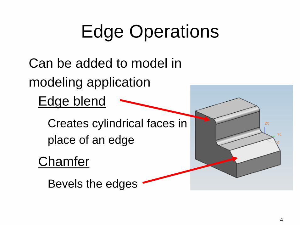
Edge Operations� Can be added to model in
modeling application� Edge blend
� Creates cylindrical faces in place of an edge
� Chamfer� Bevels the edges
5
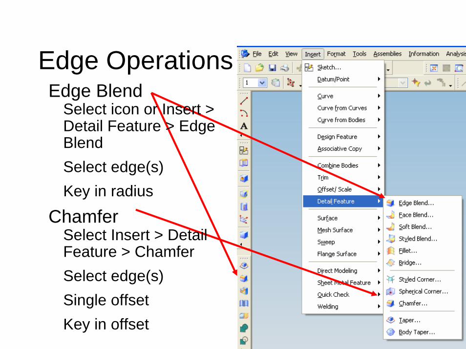
Edge Operations� Edge Blend
� Select icon or Insert > Detail Feature > Edge Blend
� Select edge(s)� Key in radius
� Chamfer� Select Insert > Detail
Feature > Chamfer� Select edge(s)� Single offset� Key in offset
6
UGNX: Basic Drafting
Note: This is NOT a course in drafting, however, engineers need to be “graphically literate”; i.e., you need to be able to read and write engineering drawings.
Today’s Objective: ● Learn basic process of converting a UG solid
model into an Engineering Drawing
7
Software Structure� UGNX is organized into:
� Applications: Gateway, Modeling, Drafting(and others)
� When a part file is opened or created, the Gateway application is entered.
� To create or edit a solid body the Modeling application is entered
� To create an engineering drawing the Drafting application is entered
8
9
10
11
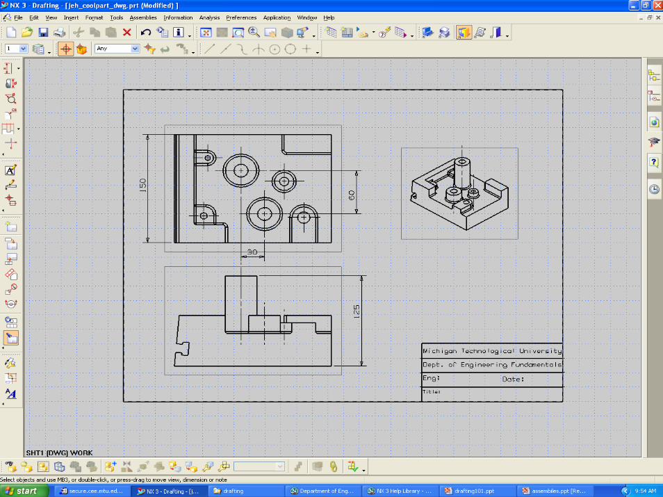
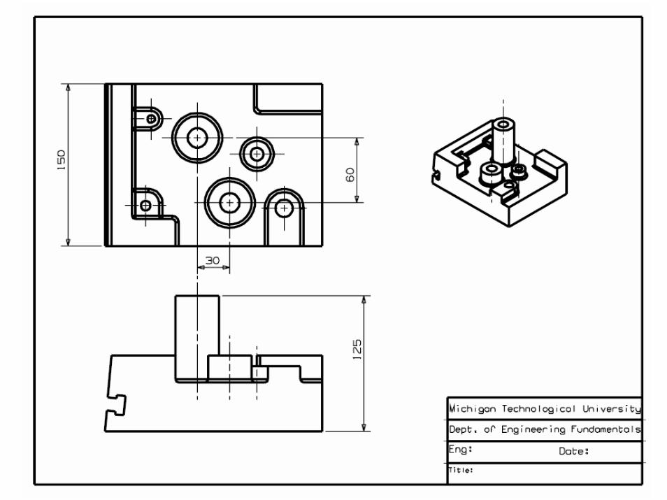
UGNX: Basic Drafting
The Drafting application lets you create drawings with views of the part, dimensions, and necessary
drafting annotations.
This application supports the drafting of engineering models in accordance with ANSI and ISO standards.
12
Short Demo …
• Drafting Application• Add Base View
• Change view, style, orientation, scale
• Add Dimensions• Add Annotation (text)
13
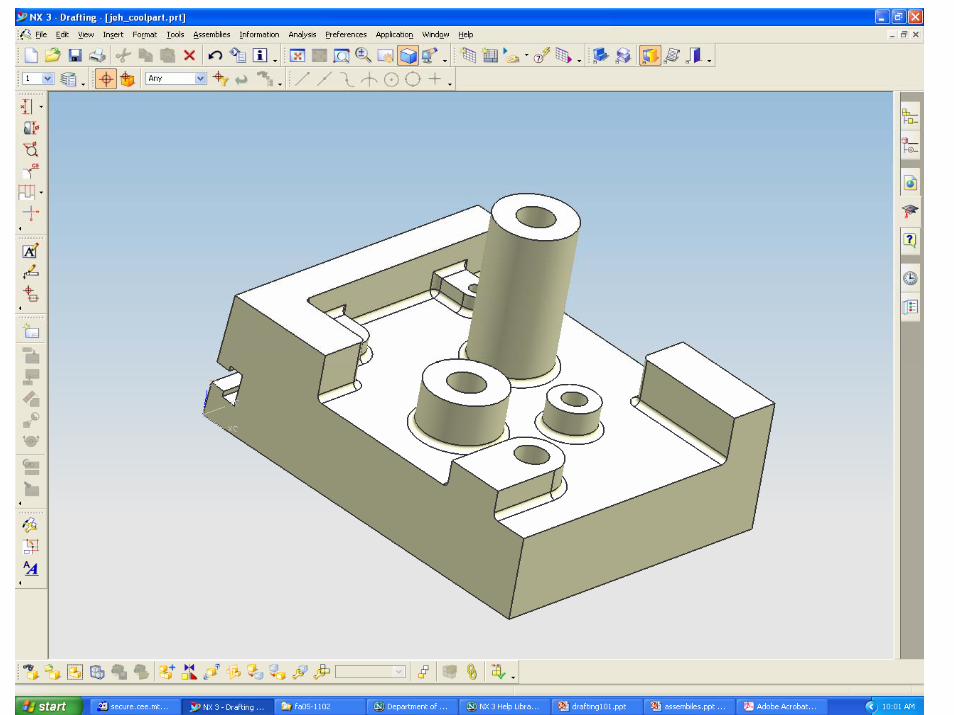
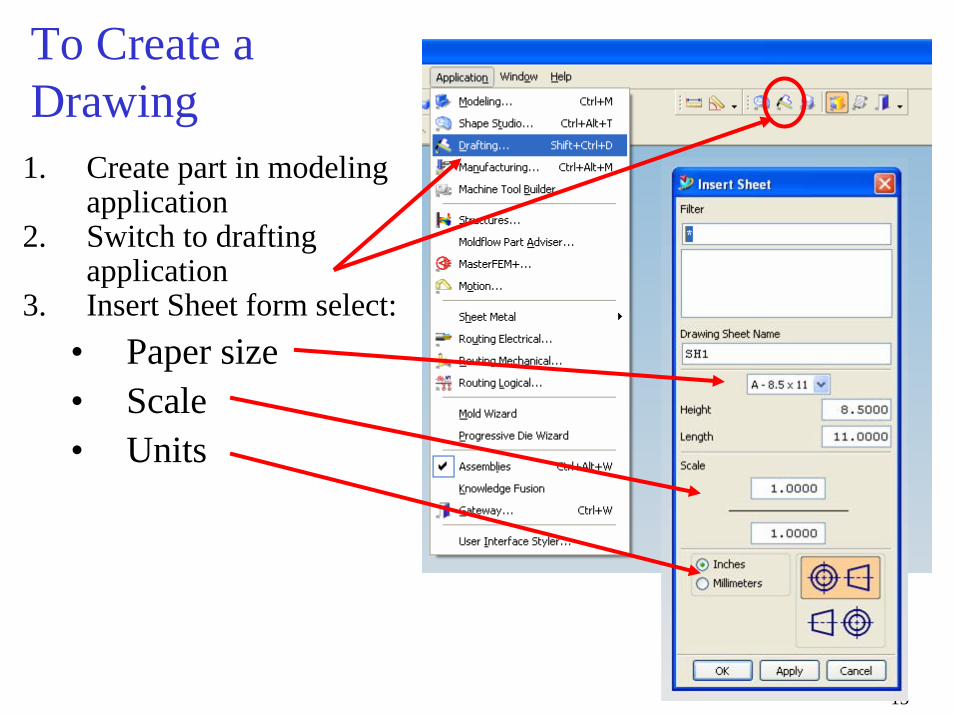
To Create a Drawing1. Create part in modeling
application2. Switch to drafting
application3. Insert Sheet form select:
• Paper size• Scale• Units
14
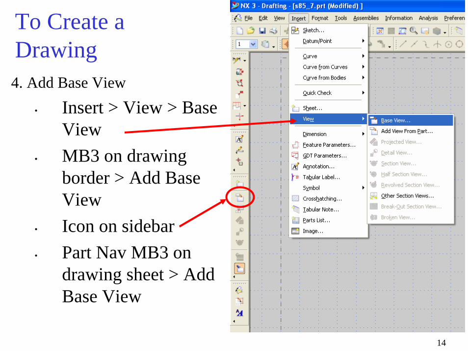
To Create a Drawing4. Add Base View
• Insert > View > Base View
• MB3 on drawing border > Add Base View
• Icon on sidebar• Part Nav MB3 on
drawing sheet > Add Base View
15
To Create a Drawing
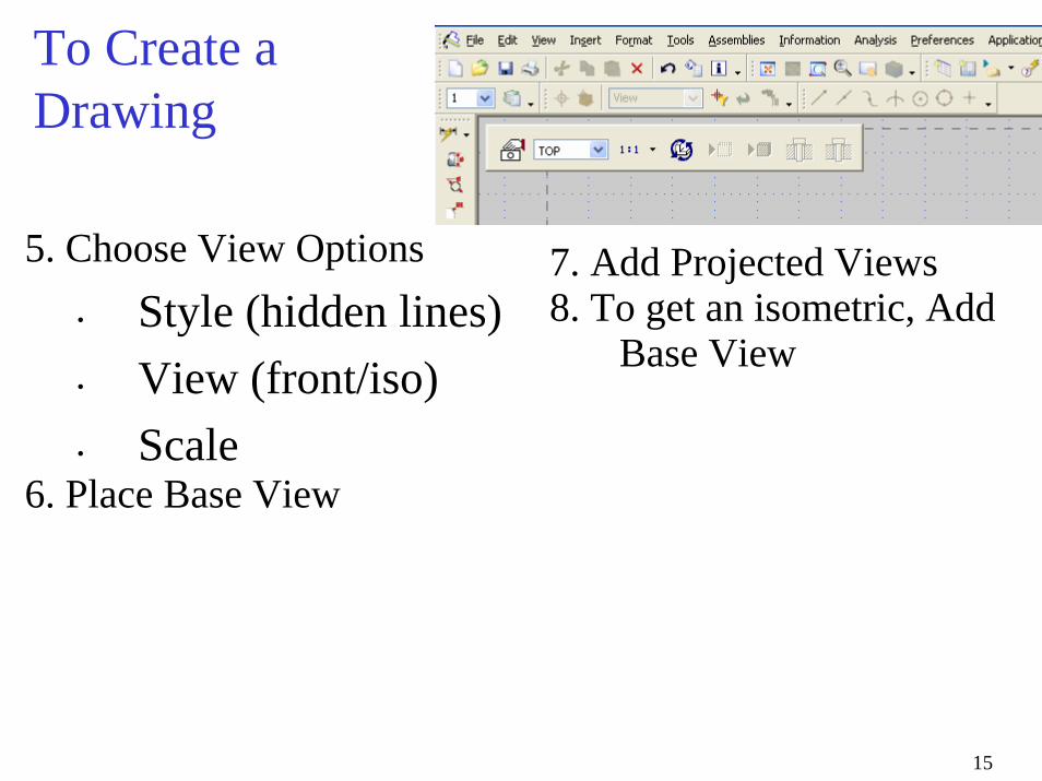
5. Choose View Options• Style (hidden lines)• View (front/iso)• Scale
6. Place Base View
7. Add Projected Views8. To get an isometric, Add
Base View
16
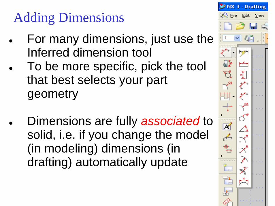
Adding Dimensions● For many dimensions, just use the
Inferred dimension tool● To be more specific, pick the tool
that best selects your part geometry
● Dimensions are fully associated to solid, i.e. if you change the model (in modeling) dimensions (in drafting) automatically update
17
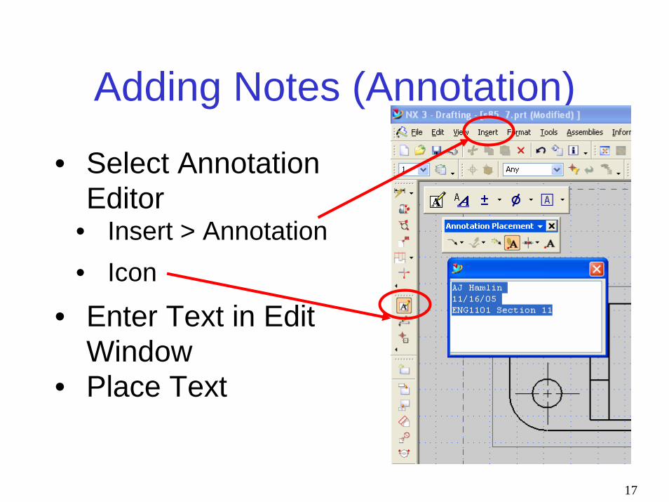
Adding Notes (Annotation)
• Select Annotation Editor
• Insert > Annotation • Icon
• Enter Text in Edit Window
• Place Text


![Full page photoPMI NX Drafting PMI Convergent Drawing a-in Concept 'i]uviu NX Drafting tu 12 Point Curve tzí-nntu Drawing INX Security 12 Password Parts wag Assemblies tu Part Assembly](https://img.pdfslide.us/doc/110x75/5e62280804007012b872580e/full-page-photo-pmi-nx-drafting-pmi-convergent-drawing-a-in-concept-iuviu-nx-drafting.jpg)