Embed Size (px)
Citation preview

Payload Separation System
By Benjamin Dirgo, Mark Majkrzak, Jason McCall,
Matthew Mylan, Kate Prentice, Alen Younan Team 11
UGRAD - Final Report Document
Submitted towards partial fulfillment of the requirements for Mechanical Engineering Design I – Spring 2014
Department of Mechanical Engineering
Northern Arizona University Flagstaff, AZ 86011

Table of Contents Chapter 1. Introduction ................................................................................................................... 4
1.1 Background ........................................................................................................................... 4
1.2 Problem Statement ................................................................................................................ 4
1.3 Introduction ........................................................................................................................... 4
1.4 Needs Identification .............................................................................................................. 5
1.5 Project Goal ........................................................................................................................... 5
Chapter 2. Final design ................................................................................................................... 5
2.1 Final Design .......................................................................................................................... 5
Table 1: Quantity of components and material selection ........................................................ 6
Figure 1: Engaged PSS ............................................................................................................ 6
Figure 2: Disengaged PSS ....................................................................................................... 6
Chapter 3. Manufacturing ............................................................................................................... 7
3.1 Overall Manufacturing Process ............................................................................................. 7
3.2 Rocket Ring ........................................................................................................................... 7
Figure 3: Rocket Ring (RR) ..................................................................................................... 8
Figure 4: RR in relation to overall design ............................................................................... 8
3.3 Payload Ring ......................................................................................................................... 8
Figure 5: Payload Ring (PR) ................................................................................................... 9
Figure 6: PR in relation to the overall design .......................................................................... 9
3.4 Keys ....................................................................................................................................... 9
Figure 7: Square end of Key .................................................................................................. 10
Figure 8: Keys in relation to the overall design ..................................................................... 10
3.5 Solenoids ............................................................................................................................. 10
Figure 9: Solenoid mounted onto RR base plate ................................................................... 11
3.6 Kick-Off Spring Coils ......................................................................................................... 11
Figure 10: Steel Springs sitting in the PR ............................................................................. 11
Chapter 4. Engineering Analysis .................................................................................................. 11
4.1 Failure Analysis ................................................................................................................... 11
Figure 11: Free body diagram of 1.5 g’s in lateral direction acting on the payload .............. 12
Chapter 5. Testing ......................................................................................................................... 13
5.1 Testing Apparatus ............................................................................................................... 13
5.2 Separation Test .................................................................................................................... 13
Figure 12: Testing apparatus ................................................................................................. 13
5.3 Solenoid Actuation Reliability ............................................................................................ 14
5.4 Results ................................................................................................................................. 14
Figure 13: Displacement of payload verse time .................................................................... 14
Figure 14: Separation Velocity of payload verse time .......................................................... 15
Figure 15: Acceleration of payload at separation verse time ................................................ 15
5.5 Discussion ........................................................................................................................... 16
Equation 1: Three-point differentiation formula ................................................................... 16
Chapter 6. Cost Analysis ............................................................................................................... 16
6.1 Bill of Materials .................................................................................................................. 16
Table 2: Bill of materials ....................................................................................................... 17
Chapter 7. Conclusions ................................................................................................................. 17
7.1 Project Planning .................................................................................................................. 17
7.2 Improvements ...................................................................................................................... 17
7.3 Conclusion ........................................................................................................................... 18
7.4 Acknowledgments ............................................................................................................... 18
References ..................................................................................................................................... 19
Appendix ....................................................................................................................................... 19
A ................................................................................................................................................ 19
B ................................................................................................................................................ 19

Chapter 1. Introduction 1.1 Background Launch vehicles such as the Pegasus that place payloads into orbit require a separation
system to release their payloads. These payloads are typically fragile and are composed of
various optical components that can be harmed when transported or by the impact of
separation once in orbit. Due to this problem, companies have designed various payload
separation systems that have become too expensive and complicated. Matthew Johns and
Steven Hengl from Orbital Sciences Corporation have requested for a new design of the
payload separation system. This new design of the system must be reduced in cost, impart
minimal shock to the payload, and be less complicated by reducing the number of parts.
The team designed, analyzed, manufactured, and tested a half-scale model of the payload
separation system for testing for ME 476 Capstone Senior Design that began in August of
2013 and was completed by May of 2014.
1.2 Problem Statement Orbital Sciences Corporation, located in Phoenix Arizona, is interested in designing a Payload
Separation System (PSS) that is lighter, less expensive, less complicated, and imparts minimal
shock levels onto the payload. The primary interest of this senior design project is to
successfully deliver a payload into polar orbit around the Earth without damage. Generally,
the design is a ring that must be strong enough to secure a payload to the front of the Pegasus
launch vehicle, separate on command, and reliably release the payload into orbit. The goal is
to improve the current payload separation system today while making sure the design is simple
so that it can be manufactured at Orbital.
1.3 Introduction Current payload separation systems are generally composed of some cylindrical ring that
is mounted on the tip of a launch vehicle just aft of the payload. The ring needs to be able
to withstand the weight of the payload and longitudinal and lateral forces caused by g’s
during maximum vehicle acceleration. Some of the external forces that need to be
considered during the design process are extreme temperatures, accelerations, vibrations,
and various other material stresses caused by the environment. The purpose of this report
is to document the design process that began in August of 2013 to the completion date on

April 25, 2014. The overall project includes trade studies, a final design, a failure analysis,
and the manufacturing process of the half-scaled model for testing. Some payloads that
might be used in industry today include: satellites, telecommunication systems, optical
systems, and experimental projects. The payloads can be delicate therefore the separation
velocity will be important to reduce. As well, the system will be less expensive by
reducing the number of parts.
1.4 Needs Identification The clients Matthew Johns and Steven Hengl contacted Northern Arizona University with a
need for a payload separation system. Currently the payload separation systems are too
expensive and the payloads are becoming damaged due to the sudden impact of the pre-loaded
springs at separation once in orbit. The need of this project is to redesign a payload separation
system that is less expensive and imparts as little shock to the payload as possible.
1.5 Project Goal Orbital Sciences Corporation is interested in a payload separation system that is lighter, less
expensive, less complicated, and imparts minimal shock to the payload. The goal is to
improve the system so that it can separate reliably with little impact to the payload. Matthew
Johns and Steven Hengl have also requested that the new design be able to be machined in-
house by Orbital Sciences, so to eliminate sub-contracting.
Chapter 2. Final design 2.1 Final Design The final design consists of a rocket ring (RR), a payload ring (PR), 4 cylindrical keys, 4
solenoids, and 8 steel coil springs. All design components, including the quantity and
material selection, can be seen in table 1. See figure 1 for an engaged isometric view of the
final design and figure 2 for an isometric view after separation in SolidWorks. The diameter
of the half-scaled payload ring is 12 inches. The base plates are fixed in a pinwheel pattern to
mount the solenoids symmetrically and therefore distribute the weight more evenly between
the quadrants. This will eliminate the issue with orienting the solenoids in abstract angles to
allow a consistent release. With the pinwheel design, the rocket ring is now divided into four
equal quadrants that will evenly distribute the load compared to the original asymmetrical
layout. To engage the system the payload ring is pressed onto the rocket ring, the keys are

manually inserted into key housings and thus securing the two rings together. The system
disengages when the solenoids are turned on. The solenoid plungers pull the keys inward,
allowing the preloaded springs sitting on the lip of the rocket ring to push off the payload
ring.
Table 1: Quantity of components and material selection
Design Components Quantity Material
Payload Ring (PR) 1 7075 Aluminum
Rocket Ring (RR) 1 7075 Aluminum
Cylindrical Key 4 Steel
Solenoid 4 n/a
Coil Springs 8 304 Stainless Steel
Figure 1: Engaged PSS
Figure 2: Disengaged PSS

Chapter 3. Manufacturing
3.1 Overall Manufacturing Process Manufacturing of the sub-scaled PSS utilized the Haas, a manual mill, a band saw, a drill press,
and a lathe for removing the excess aluminum from the payload and rocket rings. First a wax
mold was made with the same dimensions as the 12” x 12” x 1” square plates of aluminum to
ensure that the G-code generated in CAMWorks was correct. After the code was confirmed to
mill out the RR correctly, the code was then used to mill the 7075 aluminum in the Haas.
Because the machining envelope of the Haas did not reach a 12’’ diameter, the outer lip of the
RR was turned on the lathe. The inside of the payload ring was milled out using a contour path
in the Haas and then turned on the lathe in the same way that the RR was machined. Finally the
PR and RR where then clamped together so that the keyholes could be milled simultaneously
using the manual mill, allowing the holes to match up perfectly. The band saw was then used to
cut out four equally sized keys from a 3 foot 0.5’’ diameter steel rod. To attach the keys to the
plungers of the solenoids, a square tab had to be milled on one end of the key to then pin to the
plunger.
3.2 Rocket Ring The rocket ring was the most complicated piece to manufacture, and can be seen in figure 3
below. Figure 4 shows the RR in relation to the overall design. The G-code for the PR and RR
were generated using CAMWorks in conjunction with SolidWorks. The code was downloaded
into the Haas, the 12” x 12” x 1” square plate of aluminum was secured in the vise, and the
interior of the RR was milled out. To save material the code first cut out a smaller square plate
with a contour path and then removed material in a spiral motion for the pin wheel base plates.
Once finished, the CNC milling produced the inner diameter and all inner features, minus the
keyholes. The exterior lip was then turned on a lathe with extremely accurate tolerances. The
RR was turned down to have an ID 4/1000” smaller than that of the PR to minimize friction
between the two surfaces. This is a rough estimation and because extreme cold or hot
temperatures will not be tested, leaving extra space to account for thermal expansion was
neglected. Finally the keyholes were drilled, using a manual mill. To ensure a perfect mate
between the keyholes in the RR and the PR, the two rings were mated together and drilled

simultaneously. The rings were spot welded and clamped to ensure that they do not shift
during the cutting process.
Figure 3: Rocket Ring (RR)
Figure 4: RR in relation to overall design
3.3 Payload Ring The payload ring was cut with a similar process. First, a special bolt clamp was attached to
the mill to keep the outer edge of the block secure in the Haas. Next, a hole the size of the
inner diameter was drilled into the side of the block. This hole within the square block will
be used to secure the metal piece to the lathe. The attachment of the lathe works such that a
special clamp connected to the chuck will hold the block securely by the inside diameter.
The lathe then turned the outer diameter of the payload ring. Then, an end mill will be used
to drill four holes for the keys while a vise secures the payload ring and the rocket ring.
Depending on the payload, adaptor holes will need to be tapped and threaded to allow bolts
to secure the payload from the top. To hang the system with springs for possible future
testing, D shaped adaptors will be milled or attached to the outer diameter. See figure 5 for
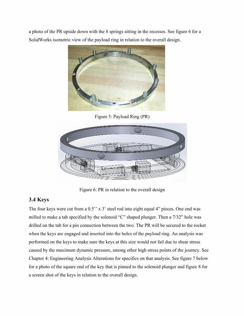
a photo of the PR upside down with the 8 springs sitting in the recesses. See figure 6 for a
SolidWorks isometric view of the payload ring in relation to the overall design.
Figure 5: Payload Ring (PR)
Figure 6: PR in relation to the overall design
3.4 Keys The four keys were cut from a 0.5’’ x 3’ steel rod into eight equal 4” pieces. One end was
milled to make a tab specified by the solenoid “C” shaped plunger. Then a 7/32” hole was
drilled on the tab for a pin connection between the two. The PR will be secured to the rocket
when the keys are engaged and inserted into the holes of the payload ring. An analysis was
performed on the keys to make sure the keys at this size would not fail due to shear stress
caused by the maximum dynamic pressure, among other high stress points of the journey. See
Chapter 4: Engineering Analysis Alterations for specifics on that analysis. See figure 7 below
for a photo of the square end of the key that is pinned to the solenoid plunger and figure 8 for
a screen shot of the keys in relation to the overall design.

Figure 7: Square end of Key
Figure 8: Keys in relation to the overall design 3.5 Solenoids The solenoids serve to provide the actuation for the keys. Four round DC solenoids were
purchased for this task. Since the actuators were round a mounting plate had to be constructed.
An aluminum L-brackets were constructed with a hole on the vertical side the size of the
solenoids to set it to get it a better base to be perfectly level for each solenoid. The other end of
the L-bracket was tapped and screwed into the base plate; two screws were used to allow better
alignment with the keys-holes. The solenoids were then wired in parallel to one switch. When
turned on, each solenoid will actuate pulling each key into their respective housing
simultaneously by 0.5”. Once the keys reach their final resting position the kick off springs will
engage, and separation will be complete. See figure 9 for a photograph of the solenoid.

Figure 9: Solenoid mounted onto RR base plate 3.6 Kick-Off Spring Coils The 8 kick off coil springs sit symmetrically inside pre-drilled holes in the payload ring. A
drill press was used to cut out eight holes along the circumference of the PR to ensure a stable
hole for the springs to sit. The coil springs convert their potential energy into kinetic energy to
separate the two halves of the system. See figure 10 for a photo of the steel springs sitting in
the holes drilled into the PR.
Figure 10: Steel Springs sitting in the PR
Chapter 4. Engineering Analysis
4.1 Failure Analysis After communicating with our clients, Matthew Johns and Steven Hengl, the only two situations
that needed to be focused on were max g’s when the launch vehicle is at max acceleration and
when 1.5 g’s acts laterally at the payloads center of gravity. The max dynamic pressure was not
a concern because the fairing at stage 1 and 2 ignition was designed to protect the system from

such forces. The forces on the system can be broken down into two forces, one in the
longitudinal direction, and one in the lateral direction. The longitudinal force corresponds to the
vertical acceleration of the rocket, and the lateral force is caused by the change in direction of
the rocket from a belly launch off of the Boeing 747 to a vertical launch into the atmosphere.
The lateral force was assumed to be 1.5 g’s, provided by Matthew and Steven. See figure 11 for
a drawing of the 1.5 g’s applied in the lateral direction at the center of gravity of the payload.
Figure 11: Free body diagram of 1.5 g’s in lateral direction acting on the payload The largest acceleration was calculated between the second stage ignition and second stage
burnout. The total g’s the PSS would experience in the longitudinal direction would then be
acceleration of 134.5 ft/s2 divided by gravity at an altitude of 471,900 ft, giving 4.2 axial g’s.
The force per key, 313.3 lbs, was calculated by multiplying the axial g’s by the weight of the
payload ring and then dividing by the four keys. As seen in figure 11, the force due to the
moment of the 1.5 g’s in the lateral direction resulted in 1125 lbs. By adding the forces and
dividing by the cross sectional area of the key, the shear force amounted to 7325.4 lbf/in-s2. The
shear yield of the steel is 42,456 lbf/in-s2, therefore the factor of safety is 5.8. This ensures that
the keys will not fail due to the lateral and longitudinal g forces that the PSS will experience at
the highest acceleration. Tear out and bearing stress of the payload ring when lateral and
longitudinal g’s are applied was also a concern. Although the tear out of the payload ring came
to 11064.1 lbf/in-s2 and bearing stress was 4639.8 lbf/in-s2, thus confirming that the PR will not
fail due to tear out or bearing stress.

Chapter 5. Testing
5.1 Testing Apparatus The testing setup consisted of a pulley system with equal weight on each end to create a
neutrally buoyant environment ultimately simulating zero gravity. The left side of the
pulley system is secured to the PSS with an added 300 lb payload. The right side of the
pulley system had a suspended counter weight to emulate outer space. By placing weight
on each side and reducing friction in the supporting pulleys as much as possible, the team
was able to replicate an almost neutrally buoyant environment. When the keys are pulled
in, the springs unload and apply an upward force onto the payload. Because there is zero
gravity, any push will create payload acceleration away from the RR.
5.2 Separation Test The team has decided to use a pulley system complete with two separate 150lb masses, shown in
figure 12. Two aluminum cross members with four eye bolts were bolted to the top of the PR to
attach to the pulley system on the left side. These cross members not only secured the PR to the
pulley system but provided a leveled base for the weights to be loaded onto. This system
emulated a neutral buoyant scenario, so that any outside force will generate displacement. A
linear pot was tied to the PR and was wired to a DAQ. The lab vi written for the DAQ recorded
displacement over some time frame. This data was then used to find the separation velocity and
acceleration at separation. The goal is to separate with a smaller velocity so that minimal shock
is imparted onto the payload, thus reducing damage.
Figure 12: Testing apparatus

5.3 Solenoid Actuation Reliability The solenoid reliability is a monumental factor in the successful launch of the payload
separation system. If the solenoids do not activate, the launch will be considered unsuccessful.
Each launch costs millions of dollars so it is very important that the PSS doesn’t fail. To
confirm the reliability of the solenoids, the separation test was performed numerous times. The
test involved manually engaging the keys, and disengaging them by actuating the solenoids.
By wiring the four solenoids in parallel, all solenoid actuate in unison. This test was done 30+
times and was successful. This gives Orbital the satisfaction that the solenoids will retract as
expected during a launch mission.
5.4 Results See figure 13 for a line graph showing the displacement verse time of three different sized
payloads. Figure 14 is a line graph showing the separation velocity of three different sized
payloads and the separation velocity with no payload. Figure 15 shows the acceleration at
separation.
Figure 13: Displacement of payload verse time
-‐0.2
0
0.2
0.4
0.6
0.8
1
1.2
1.4
1.6
1.8
0 0.2 0.4 0.6 0.8 1 1.2 1.4
Dis
plac
emen
t [in]
Time [sec]
Displacement vs. Time
90 lb load
180 lb load
270 lb load

Figure 14: Separation Velocity of payload verse time
Figure 15: Acceleration of payload at separation verse time
0 10 20 30 40 50 60 70 80 90
0 0.5 1 1.5 2 2.5
Velo
city
[in/
sec]
Time [sec]
Separation Velocity vs. Time
0 lb load
90 lb load
180 lb load
270 lb load
2.9133 2.9835
1.030533333
-‐4
-‐3
-‐2
-‐1
0
1
2
3
4
0.16 0.26 0.36 0.46 0.56 0.66
Acc
eler
atio
n [ft
/s2 ]
Time [sec]
Acceleration vs. Time
90 lb load
180 lb load
270 lb load

5.5 Discussion The data from the DAQ/VI setup was compiled into an excel worksheet for analysis and to create
graphs. Our goal was to take the displacement data from the linear potentiometer and to convert
it into velocity and acceleration of the system. To effectively analyze the system, we need to take
into account how the data was recorded. Because of the way the linear pot was connected to our
system with the line fully extended and any positive change in the displacement recording a
negative value, we needed to invert the data. Once the displacement data had been inverted we
combined the fact that the DAQ sample rate was 20 Hz to find a time for every point, and the
three-point differentiation formula, equation 1, to find the separation velocity as seen in figure
14.
Equation 1: Three-point differentiation formula
Using the same formula again we can then find acceleration of the whole system, seen in figure
15. Finding the acceleration is an important value that is specified in our client needs. Knowing
the acceleration of the system can tell how much shock is put onto the system; less acceleration
with the same displacements means less shock to the payload from our separation system.
Chapter 6. Cost Analysis 6.1 Bill of Materials The bill of materials estimate has become finalized, as all the parts have been purchased. The
largest expense that was needed to be purchase was the aluminum. This in turn was no expense
to us due to the fact that Earle M. Jorgensen Metals (EMJ Metals) generously donated a 28” x
48” x 1’’ plate of 7075-aluminum to our team. The donation reduced the previous $1118.78 bill
to a current amount of $464.54. The next largest purchase was four DC solenoids that cost
$28.00. The rest of the bill of materials consisted of machining costs from K&M Machine Tool
Inc. and testing equipment. See table 2 for the current bill of materials.

Table 2: Bill of materials
Material Quantity Unit Cost
7075 Aluminium plate 24'' x 48'' x 1'' 1 $654.24
K & M Machine Tool Inc. N/A $65.00
Carbon Steel Key 0.5'' dia x 48” long 1 $14.95
Solenoid 4 $28.00
Springs 8 $0.75
Testing Equipment N/A $266.59
Total Cost $1118.78
Chapter 7. Conclusions 7.1 Project Planning The project planning that was done via the Gantt chart during this whole process has seemed to
be a success. Each scheduled process that had to be done during the time allotted was done with
excellent quality. The Gantt charts that were used for the Fall 2013 and Spring 2014 semesters
can be seen in appendix A and B. These charts provide an organized layout of what was done
throughout the year and important deadlines. The final UGRAD presentations following a
display of the poster will be presented on April 25, 2014. The year is now coming to an end and
every one of our tasks within the Gantt chart is now complete.
7.2 Improvements As discussed in the introduction, current payload separation systems are heavy, extremely
expensive, have many complicated parts, and exert a large shock onto the payload. Our system
improves upon these problems by addressing them one by one. Our systems’ weight is
significantly reduced by using aircraft grade lightweight aluminum and by milling out the
majority of it out from a solid plate. By milling it out of a solid plate, we don’t have to use the
weight of fasteners and bolts to conform to a circular shape in our system. It is for these reasons
that we were able to reduce the weight of the system by one fifth, from a weight of 40 pounds to
a simple eight pounds.

Orbital can save millions using this improved system by machining in house with the reduction
of parts. Using our design we were able to create a half scale prototype for $1119.00. The cost is
significantly reduced because the PSS consists of 18 parts. The last design improvement that was
achieved was less shock to the payload. The measured acceleration resulted to about 1.03 ft/s2
which is less than the published acceleration of the current system used by Orbital.
7.3 Conclusion The improved PSS was a success. The failure analysis on the keys showed that the system will
not fail due to a shear force factor of safety of 5.8. The separation and reliability tests
confirmed that the PSS will successfully separate a 300 lb payload at half scale. Results
validated displacement and thus a desired separation velocity and acceleration. Because the
separation velocity was significantly reduced, the payload will not be damaged by the shock of
the pre-loaded springs. Cost was reduced dramatically because of the reduction in number of
parts. Overall, the improved PSS reliably separates with minimal shock to the payload.
7.4 Acknowledgments The team would like to acknowledge all of those who helped throughout the year. First and
foremost our clients Matthew Johns and Steven Hengl were readily available and were our
biggest support. Our original idea was to use mesh springs instead of conventional coiled springs
manufactured at Kinetic Structures. Thank you to their president, Harry Artenian, for working
with us to try and make the springs work. Although it was not a success, we all did learn a lot
from it. We would also like to give a huge thank you to Steve Warner at E.M.J. Corp. for
donating the 2’ x 4’ x 1’’ plate of 7075 aluminum. We wouldn’t have been as successful without
your help. Thank you to the professors at NAU: Dr. Srinivas Kosaraju, Dr. Robin Tuchscherer,
Dr. John Tester. Finally, thank you to the machine shop staff that helped us meet all of our
deadlines on time: Tom Cothrun, Emerson Jones, Nick Jurik, Chris Bennett.

References [1] Kyle, Ed. "Space Launch Report 2012 Launch Stats." Space Launch Report 2012 Launch
Stats. N.p., 29 Dec. 2013. Web. 05 Dec. 2013.
<http://www.spacelaunchreport.com/log2012.html>.
[2] Philpot, Timothy A. Mechanics of Materials: An Integrated Learning System. 5th ed.
Hoboken, NJ: John Wiley, 2011. Print.
[3] Rao, Singiresu S. Mechanical Vibrations. 5th ed. Upper Saddle River, NJ: Prentice Hall,
2011. Print.
[4] Baldwin, Bryan. "Pegasus User's Guide." Orbital Sciences, 1 Apr. 2010. Web. 5 Dec. 2013.
Appendix
A
B