Embed Size (px)
Citation preview
UG291: WGM110 Wi-Fi® Expansion KitUser's Guide
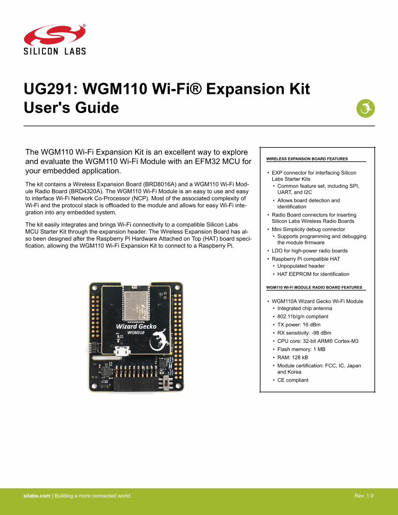
The WGM110 Wi-Fi Expansion Kit is an excellent way to exploreand evaluate the WGM110 Wi-Fi Module with an EFM32 MCU foryour embedded application.The kit contains a Wireless Expansion Board (BRD8016A) and a WGM110 Wi-Fi Mod-ule Radio Board (BRD4320A). The WGM110 Wi-Fi Module is an easy to use and easyto interface Wi-Fi Network Co-Processor (NCP). Most of the associated complexity ofWi-Fi and the protocol stack is offloaded to the module and allows for easy Wi-Fi inte-gration into any embedded system.
The kit easily integrates and brings Wi-Fi connectivity to a compatible Silicon LabsMCU Starter Kit through the expansion header. The Wireless Expansion Board has al-so been designed after the Raspberry Pi Hardware Attached on Top (HAT) board speci-fication, allowing the WGM110 Wi-Fi Expansion Kit to connect to a Raspberry Pi.
WIRELESS EXPANSION BOARD FEATURES
• EXP connector for interfacing SiliconLabs Starter Kits• Common feature set, including SPI,
UART, and I2C• Allows board detection and
identification• Radio Board connectors for inserting
Silicon Labs Wireless Radio Boards• Mini Simplicity debug connector
• Supports programming and debuggingthe module firmware
• LDO for high-power radio boards• Raspberry Pi compatible HAT
• Unpopulated header• HAT EEPROM for identification
WGM110 WI-FI MODULE RADIO BOARD FEATURES
• WGM110A Wizard Gecko Wi-Fi Module• Integrated chip antenna• 802.11b/g/n compliant• TX power: 16 dBm• RX sensitivity: -98 dBm• CPU core: 32-bit ARM® Cortex-M3• Flash memory: 1 MB• RAM: 128 kB• Module certification: FCC, IC, Japan
and Korea• CE compliant
silabs.com | Building a more connected world. Rev. 1.0

Table of Contents1. Introduction . . . . . . . . . . . . . . . . . . . . . . . . . . . . . . . . 3
1.1 Kit Contents . . . . . . . . . . . . . . . . . . . . . . . . . . . . . . 3
1.2 Getting Started . . . . . . . . . . . . . . . . . . . . . . . . . . . . . 3
2. Hardware Overview . . . . . . . . . . . . . . . . . . . . . . . . . . . . . 42.1 Hardware Layout . . . . . . . . . . . . . . . . . . . . . . . . . . . . . 4
3. Wi-Fi Expansion Kit . . . . . . . . . . . . . . . . . . . . . . . . . . . . . 53.1 Board Setup . . . . . . . . . . . . . . . . . . . . . . . . . . . . . . 5
3.2 Board Identification . . . . . . . . . . . . . . . . . . . . . . . . . . . . 6
3.3 Host Interfaces . . . . . . . . . . . . . . . . . . . . . . . . . . . . . 63.3.1 UART . . . . . . . . . . . . . . . . . . . . . . . . . . . . . . 63.3.2 SPI . . . . . . . . . . . . . . . . . . . . . . . . . . . . . . . 73.3.3 STK Pin Mapping. . . . . . . . . . . . . . . . . . . . . . . . . . . 8
4. Wireless EXP Board . . . . . . . . . . . . . . . . . . . . . . . . . . . . . 94.1 EXP Header . . . . . . . . . . . . . . . . . . . . . . . . . . . . . . 9
4.1.1 Pass-through Expansion Header . . . . . . . . . . . . . . . . . . . . .104.1.2 Expansion Header Pinout . . . . . . . . . . . . . . . . . . . . . . . .10
4.2 Raspberry Pi Connector . . . . . . . . . . . . . . . . . . . . . . . . . .114.2.1 Raspberry Pi Connector Pinout . . . . . . . . . . . . . . . . . . . . . .12
4.3 Mini Simplicity Connector . . . . . . . . . . . . . . . . . . . . . . . . . .134.3.1 Mini Simplicity Connector Pinout . . . . . . . . . . . . . . . . . . . . .14
4.4 Power Supply . . . . . . . . . . . . . . . . . . . . . . . . . . . . . .15
5. Reconfiguring the Wi-Fi Module Firmware . . . . . . . . . . . . . . . . . . . 175.1 Building the Module Firmware . . . . . . . . . . . . . . . . . . . . . . . .17
5.2 Programming the Module Firmware . . . . . . . . . . . . . . . . . . . . . .18
6. Schematics, Assembly Drawings, and BOM . . . . . . . . . . . . . . . . . . . 20
7. Kit Revision History . . . . . . . . . . . . . . . . . . . . . . . . . . . . 217.1 SLEXP4320A Revision History . . . . . . . . . . . . . . . . . . . . . . . .21
8. Document Revision History . . . . . . . . . . . . . . . . . . . . . . . . . 22
silabs.com | Building a more connected world. Rev. 1.0 | 2
1. Introduction
The WGM110 Wi-Fi Expansion Kit (OPN: SLEXP4320A) contains a Wireless Expansion Board (BRD8016A) and a WGM110 Wi-FiModule Radio Board (BRD4320A) that plug directly into each other. The core of the kit is a WGM110 Wizard Gecko Wi-Fi Module whichmakes this kit an excellent starting point for adding Wi-Fi connectivity to a compatible Silicon Labs MCU Starter Kit.
The kit connects and works out-of-the box by inserting it into the expansion header of one of these Silicon Labs MCU Starter Kits(STKs):
• EFM32 Pearl Gecko PG12 Starter Kit - SLSTK3402A• EFM32 Pearl Gecko PG1 Starter Kit - SLSTK3401A• EFM32 Giant Gecko GG11 Starter Kit - SLSTK3701A
Note: The kit is sold without a Silicon Labs MCU STK.
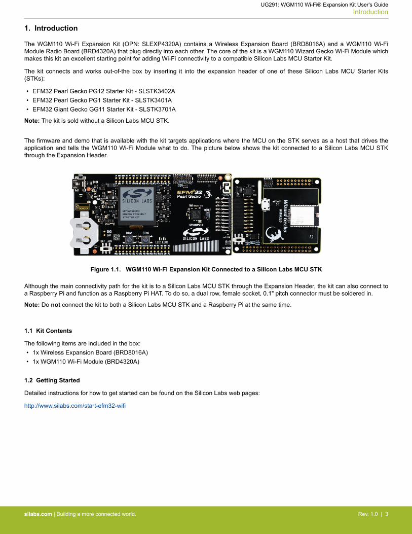
The firmware and demo that is available with the kit targets applications where the MCU on the STK serves as a host that drives theapplication and tells the WGM110 Wi-Fi Module what to do. The picture below shows the kit connected to a Silicon Labs MCU STKthrough the Expansion Header.
Figure 1.1. WGM110 Wi-Fi Expansion Kit Connected to a Silicon Labs MCU STK
Although the main connectivity path for the kit is to a Silicon Labs MCU STK through the Expansion Header, the kit can also connect toa Raspberry Pi and function as a Raspberry Pi HAT. To do so, a dual row, female socket, 0.1" pitch connector must be soldered in.
Note: Do not connect the kit to both a Silicon Labs MCU STK and a Raspberry Pi at the same time.
1.1 Kit Contents
The following items are included in the box:• 1x Wireless Expansion Board (BRD8016A)• 1x WGM110 Wi-Fi Module (BRD4320A)
1.2 Getting Started
Detailed instructions for how to get started can be found on the Silicon Labs web pages:
http://www.silabs.com/start-efm32-wifi
UG291: WGM110 Wi-Fi® Expansion Kit User's GuideIntroduction
silabs.com | Building a more connected world. Rev. 1.0 | 3
2. Hardware Overview
2.1 Hardware Layout
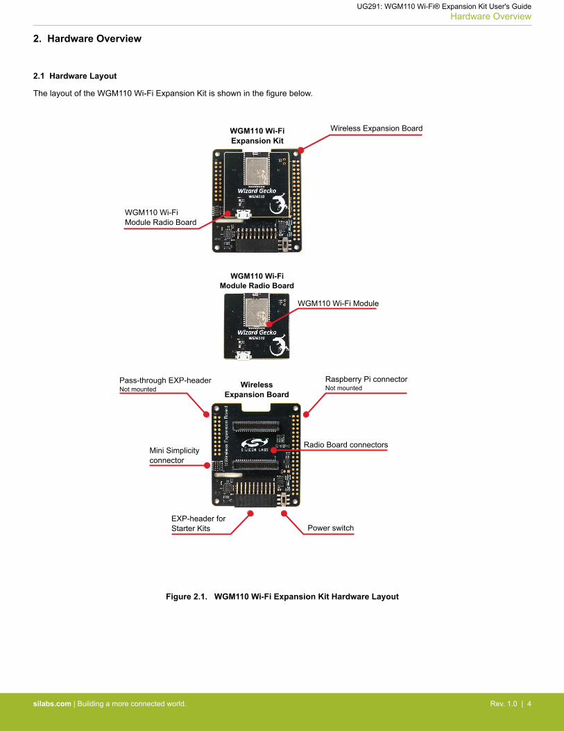
The layout of the WGM110 Wi-Fi Expansion Kit is shown in the figure below.
EXP-header forStarter Kits Power switch
Pass-through EXP-headerNot mounted
Mini Simplicityconnector
Raspberry Pi connectorNot mounted
Radio Board connectors
WirelessExpansion Board
WGM110 Wi-Fi Module Radio Board
WGM110 Wi-Fi Module
WGM110 Wi-FiExpansion Kit
Wireless Expansion Board
WGM110 Wi-Fi Module Radio Board
Figure 2.1. WGM110 Wi-Fi Expansion Kit Hardware Layout
UG291: WGM110 Wi-Fi® Expansion Kit User's GuideHardware Overview
silabs.com | Building a more connected world. Rev. 1.0 | 4
3. Wi-Fi Expansion Kit
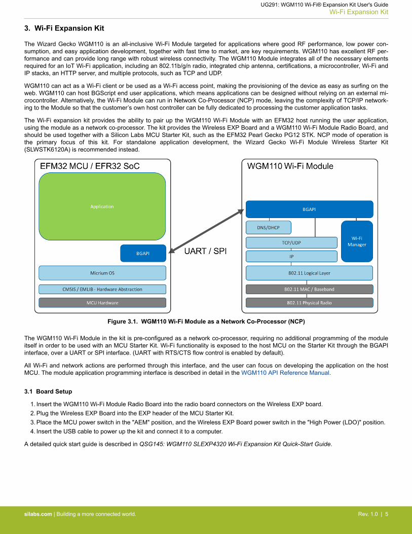
The Wizard Gecko WGM110 is an all-inclusive Wi-Fi Module targeted for applications where good RF performance, low power con-sumption, and easy application development, together with fast time to market, are key requirements. WGM110 has excellent RF per-formance and can provide long range with robust wireless connectivity. The WGM110 Module integrates all of the necessary elementsrequired for an IoT Wi-Fi application, including an 802.11b/g/n radio, integrated chip antenna, certifications, a microcontroller, Wi-Fi andIP stacks, an HTTP server, and multiple protocols, such as TCP and UDP.
WGM110 can act as a Wi-Fi client or be used as a Wi-Fi access point, making the provisioning of the device as easy as surfing on theweb. WGM110 can host BGScript end user applications, which means applications can be designed without relying on an external mi-crocontroller. Alternatively, the Wi-Fi Module can run in Network Co-Processor (NCP) mode, leaving the complexity of TCP/IP network-ing to the Module so that the customer’s own host controller can be fully dedicated to processing the customer application tasks.
The Wi-Fi expansion kit provides the ability to pair up the WGM110 Wi-Fi Module with an EFM32 host running the user application,using the module as a network co-processor. The kit provides the Wireless EXP Board and a WGM110 Wi-Fi Module Radio Board, andshould be used together with a Silicon Labs MCU Starter Kit, such as the EFM32 Pearl Gecko PG12 STK. NCP mode of operation isthe primary focus of this kit. For standalone application development, the Wizard Gecko Wi-Fi Module Wireless Starter Kit(SLWSTK6120A) is recommended instead.
Figure 3.1. WGM110 Wi-Fi Module as a Network Co-Processor (NCP)
The WGM110 Wi-Fi Module in the kit is pre-configured as a network co-processor, requiring no additional programming of the moduleitself in order to be used with an MCU Starter Kit. Wi-Fi functionality is exposed to the host MCU on the Starter Kit through the BGAPIinterface, over a UART or SPI interface. (UART with RTS/CTS flow control is enabled by default).
All Wi-Fi and network actions are performed through this interface, and the user can focus on developing the application on the hostMCU. The module application programming interface is described in detail in the WGM110 API Reference Manual.
3.1 Board Setup
1. Insert the WGM110 Wi-Fi Module Radio Board into the radio board connectors on the Wireless EXP board.2. Plug the Wireless EXP Board into the EXP header of the MCU Starter Kit.3. Place the MCU power switch in the "AEM" position, and the Wireless EXP Board power switch in the "High Power (LDO)" position.4. Insert the USB cable to power up the kit and connect it to a computer.
A detailed quick start guide is described in QSG145: WGM110 SLEXP4320 Wi-Fi Expansion Kit Quick-Start Guide.
UG291: WGM110 Wi-Fi® Expansion Kit User's GuideWi-Fi Expansion Kit
silabs.com | Building a more connected world. Rev. 1.0 | 5
3.2 Board Identification
The Starter Kit and Wireless EXP board provide identification of all the connected boards. This detection and identification is used bythe Simplicity Studio tool to present the correct documentation and software examples.
The kit is able to detect which radio board is inserted, but requires the board to be inserted at power-on. It is therefore important toalways connect the boards together before inserting the USB cable into the starter kit (powering on the boards).
3.3 Host Interfaces
There are two available host interfaces on the WGM110 Wi-Fi Expansion Kit, one of which can be used to connect the WGM110 Wi-FiModule to an external host. The production firmware on the WGM110 Wi-Fi Module uses UART with RTS/CTS flow control as the de-fault host interface. For information on how to reprogram the firmware on the WGM110 Wi-Fi Module, see Section 5. Reconfiguring theWi-Fi Module Firmware.
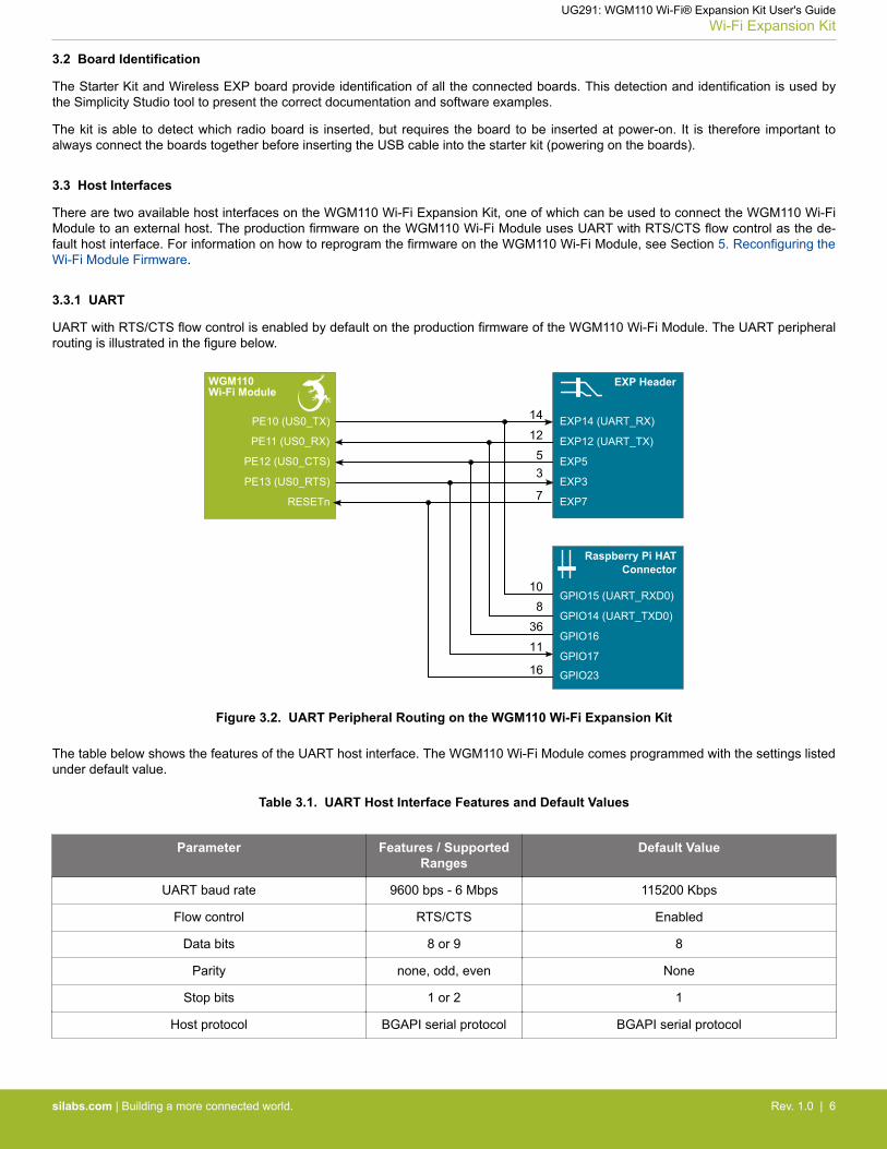
3.3.1 UART
UART with RTS/CTS flow control is enabled by default on the production firmware of the WGM110 Wi-Fi Module. The UART peripheralrouting is illustrated in the figure below.
EXP HeaderWGM110Wi-Fi Module
EXP14 (UART_RX)
EXP12 (UART_TX)
EXP5
EXP3
Raspberry Pi HATConnector
GPIO15 (UART_RXD0)
GPIO14 (UART_TXD0)
GPIO16
GPIO17
GPIO23
PE10 (US0_TX)
PE11 (US0_RX)
PE12 (US0_CTS)
PE13 (US0_RTS)
141253
108
3611
RESETn EXP77
16
Figure 3.2. UART Peripheral Routing on the WGM110 Wi-Fi Expansion Kit
The table below shows the features of the UART host interface. The WGM110 Wi-Fi Module comes programmed with the settings listedunder default value.
Table 3.1. UART Host Interface Features and Default Values
Parameter Features / SupportedRanges
Default Value
UART baud rate 9600 bps - 6 Mbps 115200 Kbps
Flow control RTS/CTS Enabled
Data bits 8 or 9 8
Parity none, odd, even None
Stop bits 1 or 2 1
Host protocol BGAPI serial protocol BGAPI serial protocol
UG291: WGM110 Wi-Fi® Expansion Kit User's GuideWi-Fi Expansion Kit
silabs.com | Building a more connected world. Rev. 1.0 | 6
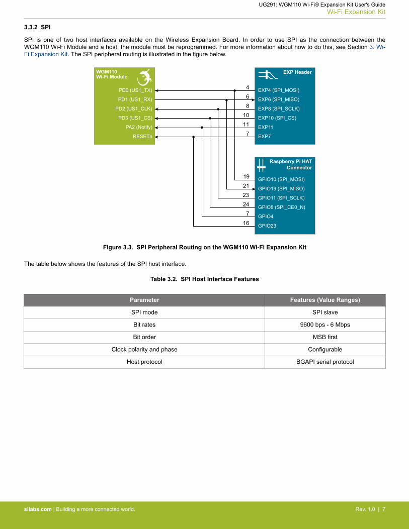
3.3.2 SPI
SPI is one of two host interfaces available on the Wireless Expansion Board. In order to use SPI as the connection between theWGM110 Wi-Fi Module and a host, the module must be reprogrammed. For more information about how to do this, see Section 3. Wi-Fi Expansion Kit. The SPI peripheral routing is illustrated in the figure below.
EXP HeaderWGM110Wi-Fi Module
EXP4 (SPI_MOSI)
EXP6 (SPI_MISO)
EXP8 (SPI_SCLK)
EXP10 (SPI_CS)
GPIO10 (SPI_MOSI)
GPIO19 (SPI_MISO)
GPIO11 (SPI_SCLK)
GPIO8 (SPI_CE0_N)
Raspberry Pi HATConnector
PD0 (US1_TX)
PD1 (US1_RX)
PD2 (US1_CLK)
PD3 (US1_CS)
468
10
19212324
PA2 (Notify) EXP11
GPIO47
11
RESETn EXP77
16 GPIO23
Figure 3.3. SPI Peripheral Routing on the WGM110 Wi-Fi Expansion Kit
The table below shows the features of the SPI host interface.
Table 3.2. SPI Host Interface Features
Parameter Features (Value Ranges)
SPI mode SPI slave
Bit rates 9600 bps - 6 Mbps
Bit order MSB first
Clock polarity and phase Configurable
Host protocol BGAPI serial protocol
UG291: WGM110 Wi-Fi® Expansion Kit User's GuideWi-Fi Expansion Kit
silabs.com | Building a more connected world. Rev. 1.0 | 7
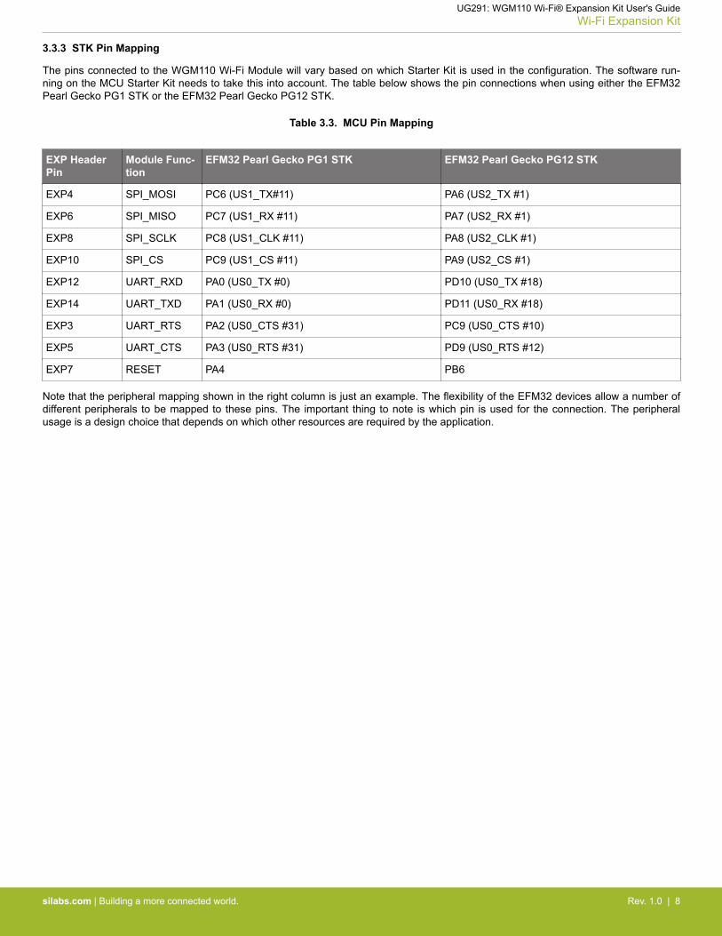
3.3.3 STK Pin Mapping
The pins connected to the WGM110 Wi-Fi Module will vary based on which Starter Kit is used in the configuration. The software run-ning on the MCU Starter Kit needs to take this into account. The table below shows the pin connections when using either the EFM32Pearl Gecko PG1 STK or the EFM32 Pearl Gecko PG12 STK.
Table 3.3. MCU Pin Mapping
EXP HeaderPin
Module Func-tion
EFM32 Pearl Gecko PG1 STK EFM32 Pearl Gecko PG12 STK
EXP4 SPI_MOSI PC6 (US1_TX#11) PA6 (US2_TX #1)
EXP6 SPI_MISO PC7 (US1_RX #11) PA7 (US2_RX #1)
EXP8 SPI_SCLK PC8 (US1_CLK #11) PA8 (US2_CLK #1)
EXP10 SPI_CS PC9 (US1_CS #11) PA9 (US2_CS #1)
EXP12 UART_RXD PA0 (US0_TX #0) PD10 (US0_TX #18)
EXP14 UART_TXD PA1 (US0_RX #0) PD11 (US0_RX #18)
EXP3 UART_RTS PA2 (US0_CTS #31) PC9 (US0_CTS #10)
EXP5 UART_CTS PA3 (US0_RTS #31) PD9 (US0_RTS #12)
EXP7 RESET PA4 PB6
Note that the peripheral mapping shown in the right column is just an example. The flexibility of the EFM32 devices allow a number ofdifferent peripherals to be mapped to these pins. The important thing to note is which pin is used for the connection. The peripheralusage is a design choice that depends on which other resources are required by the application.
UG291: WGM110 Wi-Fi® Expansion Kit User's GuideWi-Fi Expansion Kit
silabs.com | Building a more connected world. Rev. 1.0 | 8
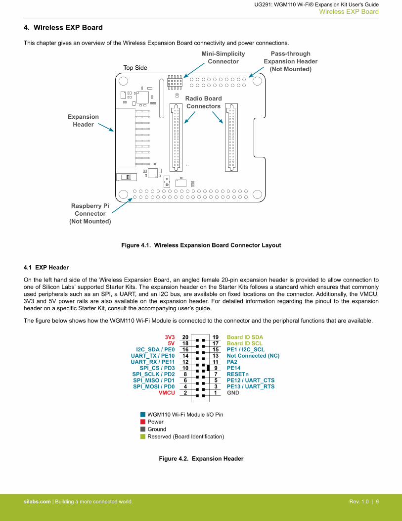
4. Wireless EXP Board
This chapter gives an overview of the Wireless Expansion Board connectivity and power connections.
EXP2 | VMCU
EXP4 | SPI_MOSI | PC6
EXP6 | SPI_MISO | PC7
EXP8 | SPI_SCLK | PC8
EXP10 | SPI_CS | PC9
EXP12 | UART_TX | PA0
EXP14 | UART_RX | PA1
EXP16 | I2C_SDA | PC10
EXP18 | 5V
EXP20 | 3V3
EXP1 | GND
EXP3 | UART_CTS | PA2
EXP5 | UART_RTS | PA3
EXP7 | PF3
EXP9 | PF4
EXP11 | PF5
EXP13 | PF6
EXP15 | PC11 | I2C_SCL
EXP17 | BOARD_ID_SCL
EXP19 | BOARD_ID_SDA
Expansion Header Breakout
USB Micro-B Connector
Mini-Simplicity Connector
Top Side
Mini-Simplicity Connector
VMCU
RST
VCOM_TX | PA0
SWDIO | PF1
PTI_FRAME | PB13
GND
VCOM_RX | PA1
SWO | PF2
SWCLK | PF0
PTI_DATA | PB12
1
3
5
7
9
11
13
15
17
19
2
4
6
8
10
12
14
16
18
20
VBAT
GND
Battery Connector(on reverse side)
Hirose DF13C-2P-1.25V
ExpansionHeader
Radio BoardConnectors
Raspberry PiConnector
(Not Mounted)
Pass-throughExpansion Header
(Not Mounted)
Mini-SimplicityConnector
Top Side
Figure 4.1. Wireless Expansion Board Connector Layout
4.1 EXP Header
On the left hand side of the Wireless Expansion Board, an angled female 20-pin expansion header is provided to allow connection toone of Silicon Labs’ supported Starter Kits. The expansion header on the Starter Kits follows a standard which ensures that commonlyused peripherals such as an SPI, a UART, and an I2C bus, are available on fixed locations on the connector. Additionally, the VMCU,3V3 and 5V power rails are also available on the expansion header. For detailed information regarding the pinout to the expansionheader on a specific Starter Kit, consult the accompanying user’s guide.
The figure below shows how the WGM110 Wi-Fi Module is connected to the connector and the peripheral functions that are available.
124
86
10
35
97
12131411
15161718
20 19
VMCUSPI_MOSI / PD0SPI_MISO / PD1SPI_SCLK / PD2
SPI_CS / PD3UART_RX / PE11UART_TX / PE10
I2C_SDA / PE05V
3V3
GNDPE13 / UART_RTSPE12 / UART_CTSRESETnPE14PA2Not Connected (NC)PE1 / I2C_SCL
Board ID SDABoard ID SCL
Reserved (Board Identification)
WGM110 Wi-Fi Module I/O Pin
Figure 4.2. Expansion Header
UG291: WGM110 Wi-Fi® Expansion Kit User's GuideWireless EXP Board
silabs.com | Building a more connected world. Rev. 1.0 | 9
4.1.1 Pass-through Expansion Header
The Wireless Expansion Board features a footprint for a secondary expansion header. The signals from the expansion header are di-rectly tied to the corresponding pins in the footprint, allowing daisy-chaining of additional expansion boards if a connector is soldered in.
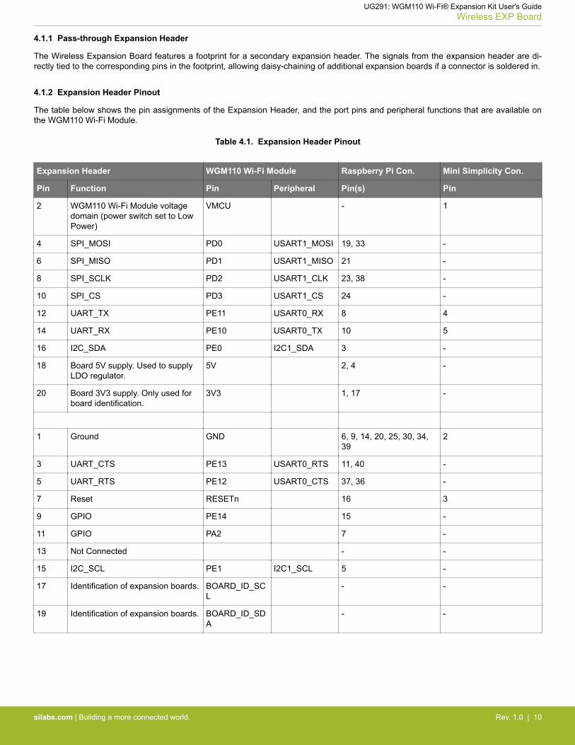
4.1.2 Expansion Header Pinout
The table below shows the pin assignments of the Expansion Header, and the port pins and peripheral functions that are available onthe WGM110 Wi-Fi Module.
Table 4.1. Expansion Header Pinout
Expansion Header WGM110 Wi-Fi Module Raspberry Pi Con. Mini Simplicity Con.
Pin Function Pin Peripheral Pin(s) Pin
2 WGM110 Wi-Fi Module voltagedomain (power switch set to LowPower)
VMCU - 1
4 SPI_MOSI PD0 USART1_MOSI 19, 33 -
6 SPI_MISO PD1 USART1_MISO 21 -
8 SPI_SCLK PD2 USART1_CLK 23, 38 -
10 SPI_CS PD3 USART1_CS 24 -
12 UART_TX PE11 USART0_RX 8 4
14 UART_RX PE10 USART0_TX 10 5
16 I2C_SDA PE0 I2C1_SDA 3 -
18 Board 5V supply. Used to supplyLDO regulator.
5V 2, 4 -
20 Board 3V3 supply. Only used forboard identification.
3V3 1, 17 -
1 Ground GND 6, 9, 14, 20, 25, 30, 34,39
2
3 UART_CTS PE13 USART0_RTS 11, 40 -
5 UART_RTS PE12 USART0_CTS 37, 36 -
7 Reset RESETn 16 3
9 GPIO PE14 15 -
11 GPIO PA2 7 -
13 Not Connected - -
15 I2C_SCL PE1 I2C1_SCL 5 -
17 Identification of expansion boards. BOARD_ID_SCL
- -
19 Identification of expansion boards. BOARD_ID_SDA
- -
UG291: WGM110 Wi-Fi® Expansion Kit User's GuideWireless EXP Board
silabs.com | Building a more connected world. Rev. 1.0 | 10

4.2 Raspberry Pi Connector
On the bottom side of the Wireless Expansion Board, a dual row, female socket, 0.1" pitch connector can be soldered in to allow theWGM110 Wi-Fi Expansion Kit to act as a Raspberry Pi Hardware Attached on Top (HAT) board.
The figure below shows how the WGM110 Wi-Fi Module is connected to the connector and the peripheral functions that are available.
Reserved (Board Identification)
WGM110 Wi-Fi Module I/O Pin
GND PE12 PC14 PD0 PC1
PB12RPI_ID_SD
GND SPI_SCLK / PD2 SPI_MISO / PD1
PE13PD2PE12 / UART_CTSGNDPC15GNDRPI_ID_SCPC0
PA6PD3 / SPI_CS
SPI_MOSI / PD03V3
PE14 PB11
UART_RTS / PE13GND PA2
I2C_SCL / PE1 I2C_SDA / PE0
3V3
GNDPE15RESETnGNDPC13PE10 / UART_TXPE11 / UART_RXGND
5V5V
403937
3335
31
3836
3234
29282730
26252423
21 222019
17
1315
11
1816
1214
987
10
6543
1 2
Figure 4.3. Raspberry Pi Connector
UG291: WGM110 Wi-Fi® Expansion Kit User's GuideWireless EXP Board
silabs.com | Building a more connected world. Rev. 1.0 | 11
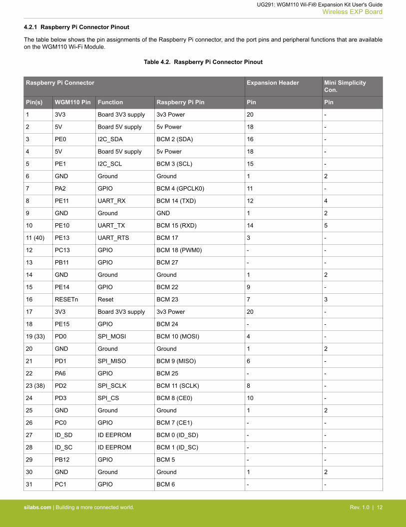
4.2.1 Raspberry Pi Connector Pinout
The table below shows the pin assignments of the Raspberry Pi connector, and the port pins and peripheral functions that are availableon the WGM110 Wi-Fi Module.
Table 4.2. Raspberry Pi Connector Pinout
Raspberry Pi Connector Expansion Header Mini SimplicityCon.
Pin(s) WGM110 Pin Function Raspberry Pi Pin Pin Pin
1 3V3 Board 3V3 supply 3v3 Power 20 -
2 5V Board 5V supply 5v Power 18 -
3 PE0 I2C_SDA BCM 2 (SDA) 16 -
4 5V Board 5V supply 5v Power 18 -
5 PE1 I2C_SCL BCM 3 (SCL) 15 -
6 GND Ground Ground 1 2
7 PA2 GPIO BCM 4 (GPCLK0) 11 -
8 PE11 UART_RX BCM 14 (TXD) 12 4
9 GND Ground GND 1 2
10 PE10 UART_TX BCM 15 (RXD) 14 5
11 (40) PE13 UART_RTS BCM 17 3 -
12 PC13 GPIO BCM 18 (PWM0) - -
13 PB11 GPIO BCM 27 - -
14 GND Ground Ground 1 2
15 PE14 GPIO BCM 22 9 -
16 RESETn Reset BCM 23 7 3
17 3V3 Board 3V3 supply 3v3 Power 20 -
18 PE15 GPIO BCM 24 - -
19 (33) PD0 SPI_MOSI BCM 10 (MOSI) 4 -
20 GND Ground Ground 1 2
21 PD1 SPI_MISO BCM 9 (MISO) 6 -
22 PA6 GPIO BCM 25 - -
23 (38) PD2 SPI_SCLK BCM 11 (SCLK) 8 -
24 PD3 SPI_CS BCM 8 (CE0) 10 -
25 GND Ground Ground 1 2
26 PC0 GPIO BCM 7 (CE1) - -
27 ID_SD ID EEPROM BCM 0 (ID_SD) - -
28 ID_SC ID EEPROM BCM 1 (ID_SC) - -
29 PB12 GPIO BCM 5 - -
30 GND Ground Ground 1 2
31 PC1 GPIO BCM 6 - -
UG291: WGM110 Wi-Fi® Expansion Kit User's GuideWireless EXP Board
silabs.com | Building a more connected world. Rev. 1.0 | 12

Raspberry Pi Connector Expansion Header Mini SimplicityCon.
Pin(s) WGM110 Pin Function Raspberry Pi Pin Pin Pin
32 PC15 GPIO BCM 12 (PWM0) - -
33 (19) PD0 GPIO BCM 13 (PWM1) 4 -
34 GND Ground Ground 1 2
35 PC14 GPIO BCM 19 (MISO) - -
36 (37) PE12 UART_CTS BCM 16 5 -
37 (36) PE12 GPIO BCM 26 5 -
38 (23) PD2 GPIO BCM 20 (MOSI) 8 -
39 GND Ground Ground 1 2
40 (11) PE13 GPIO BCM 21 (SCLK) 3 -
Note: Several of the Raspberry Pi GPIO pins are connected together when the WGM110 Wi-Fi Module Radio Board is inserted. This isbecause of connections on the radio board itself, and are not because they are connected together on the Wireless EXP Board. Caremust be taken when driving these pins to avoid creating short circuits.
4.3 Mini Simplicity Connector
The Mini Simplicity connector, featured on the WGM110 Wi-Fi Expansion Kit, allows the use of an external debugger, such as thosefeatured on one of the kits listed under Section 1. Introduction. In addition to providing serial wire debug (SWD) and virtual COM portfunctionality, the debugger on the STKs can also support advanced energy profiling tools. For more information see AN958: Debuggingand Programming Interfaces for Custom Designs.
Note: Using the Mini Simplicity connector with the kit requires a Silicon Labs debug adapter kit (OPN: SLSDA001A).
The pinout of the connector, as seen from the WGM110 Wi-Fi Module side, is illustrated in the figure below.
VMCU 13RST5VCOM_TX
9Not Connected (NC)7SWDIO
2 GND4 VCOM_RX6 SWO8 SWCLK10 Not Connected (NC)
Figure 4.4. Mini Simplicity Connector
UG291: WGM110 Wi-Fi® Expansion Kit User's GuideWireless EXP Board
silabs.com | Building a more connected world. Rev. 1.0 | 13
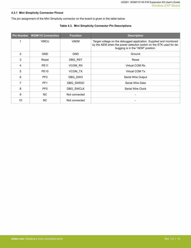
4.3.1 Mini Simplicity Connector Pinout
The pin assignment of the Mini Simplicity connector on the board is given in the table below.
Table 4.3. Mini Simplicity Connector Pin Descriptions
Pin Number WGM110 Connection Function Description
1 VMCU VAEM Target voltage on the debugged application. Supplied and monitoredby the AEM when the power selection switch on the STK used for de-
bugging is in the "AEM" position.
2 GND GND Ground
3 Reset DBG_RST Reset
4 PE11 VCOM_RX Virtual COM Rx
5 PE10 VCOM_TX Virtual COM Tx
6 PF2 DBG_SWO Serial Wire Output
7 PF1 DBG_SWDIO Serial Wire Data
8 PF0 DBG_SWCLK Serial Wire Clock
9 NC Not connected -
10 NC Not connected -
UG291: WGM110 Wi-Fi® Expansion Kit User's GuideWireless EXP Board
silabs.com | Building a more connected world. Rev. 1.0 | 14

4.4 Power Supply
There are three ways to provide power to the kit:• The kit can be connected to, and powered by, a Silicon Labs MCU STK• The kit can be connected to, and powered by, a Raspberry Pi• If the kit is connected to a Silicon Labs MCU STK, the kit can also be powered through the Mini Simplicity Connector.
Note: Connecting the WGM110 Wi-Fi Expansion Kit to both an STK and a Raspberry Pi at the same time is not a valid option.
When connected to a Silicon Labs MCU STK, the WGM110 Wi-Fi Module can either be powered by the VMCU rail present on the Ex-pansion Header, or through an LDO regulator on board the Wireless Expansion Board. The LDO regulator draws power from the 5Vnet, and hence, the power consumption of the WGM110 Wi-Fi Module will not be included in any AEM measurements performed by theMCU STK. A mechanical power switch on the Wireless Expansion Board is used to select between Low Power (AEM) mode and HighPower (LDO) mode. When the switch is set to Low Power (AEM) mode, the WGM110 Wi-Fi Module is connected to the VMCU net onthe Expansion Header. When the switch is set to High Power (LDO) mode, the WGM110 Wi-Fi Module is connected to the output of theLDO. For applications requiring high power consumption, or when the WGM110 Wi-Fi Expansion Kit is connected to a Raspberry Pi,the power switch must be set to High Power (LDO) mode.
The power topology is illustrated in the figure below.
ExpansionHeader
Raspberry PiConnector
Mini SimplicityConnector
PowerSwitch
LowPower(AEM)
HighPower(LDO)
VMCU
LDOIN OUT
3.3 V5V
3V3
WGM110Wi-Fi Module
5V
Figure 4.5. WGM110 Wi-Fi Expansion Kit Power Topology
The power supply options are summarized in Table 4.4 WGM110 Wi-Fi Expansion Kit Power Options on page 15. Information onplacement of the power switch and the connectors can be found in Section 2.1 Hardware Layout.
Table 4.4. WGM110 Wi-Fi Expansion Kit Power Options
Host Host MCUSTK Power
Switch
Debugger (STK) PowerSwitch
Wireless Expansion BoardPower Switch
Power Source
MCU STK AEM BAT Low power (AEM) MCU STK provides power toboth MCU and radio board.
MCU STK AEM BAT High power (LDO) MCU is powered by MCUSTK. Radio board is pow-ered by LDO on the Wire-
less Expansion Board
MCU STK BAT AEM Low power (AEM) External STK debugger pro-vides power to both MCU
and radio board.
UG291: WGM110 Wi-Fi® Expansion Kit User's GuideWireless EXP Board
silabs.com | Building a more connected world. Rev. 1.0 | 15

Host Host MCUSTK Power
Switch
Debugger (STK) PowerSwitch
Wireless Expansion BoardPower Switch
Power Source
Raspberry Pi - BAT High power (LDO) Radio board is powered byLDO on the Wireless Expan-
sion Board
Note: It is important to only use the configurations provided in the table above in order to avoid any power conflicts. Furthermore, it isimportant to make sure that the coin cell battery holder is empty whenever the power switch should be set to BAT.
UG291: WGM110 Wi-Fi® Expansion Kit User's GuideWireless EXP Board
silabs.com | Building a more connected world. Rev. 1.0 | 16
5. Reconfiguring the Wi-Fi Module Firmware
The WGM110 Wi-Fi Module has several hardware interfaces that can be enabled, including the SPI slave interface, the USB device,and the micro-SD card. To configure the module's hardware interfaces, the module firmware needs to be recompiled and re-program-med.
The Mini Simplicity connector on the Wireless EXP Board provides a Serial Wire Debug interface to the WGM110 module, which can beused to upload the reconfigured module firmware. Alternatively, the Device Firmware Update protocol (DFU) can be used to update thefirmware over the UART or SPI interface.
5.1 Building the Module Firmware
Configuring the hardware interface settings of the WGM110 can be done using either the BGBuild command line tool, or the GUI basedBGTool. UG161: WGM110 Wi-Fi Module Configuration Guide explains in detail how to configure the hardware interfaces of theWGM110 Wi-Fi Module.
UG291: WGM110 Wi-Fi® Expansion Kit User's GuideReconfiguring the Wi-Fi Module Firmware
silabs.com | Building a more connected world. Rev. 1.0 | 17

5.2 Programming the Module Firmware
The 10-pin Mini Simplicity connector on the Wireless EXP Board provides a Serial Wire Debug connection to the WGM110 Wi-Fi Mod-ule that can be used to upload the re-configured module firmware. Silicon Labs offers a Simplicity Debug Adapter Board that connectsbetween the two 20-pin debug connectors on Silicon Labs Starter Kits and the 10-pin connector on the Wireless EXP Board.
Figure 5.1. MCU Starter Kit as Programmer for WGM110 Wi-Fi Module Radio Board
When programming the module firmware using the BGTool, the Starter Kit's debug multiplexer must be set to "Debug OUT". This allowsthe kit to program the module connected through the debug adapter instead of the on-board MCU. The Simplicity Studio tool provides adevice configuration utility that can change the kit's debug mode between "MCU" and "OUT".
UG291: WGM110 Wi-Fi® Expansion Kit User's GuideReconfiguring the Wi-Fi Module Firmware
silabs.com | Building a more connected world. Rev. 1.0 | 18
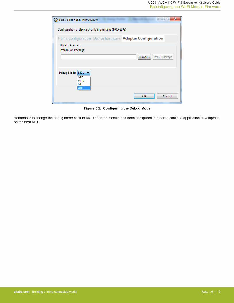
Figure 5.2. Configuring the Debug Mode
Remember to change the debug mode back to MCU after the module has been configured in order to continue application developmenton the host MCU.
UG291: WGM110 Wi-Fi® Expansion Kit User's GuideReconfiguring the Wi-Fi Module Firmware
silabs.com | Building a more connected world. Rev. 1.0 | 19

6. Schematics, Assembly Drawings, and BOM
Schematics, assembly drawings, and bill of materials (BOM) are available through Simplicity Studio when the kit documentation pack-age has been installed.
UG291: WGM110 Wi-Fi® Expansion Kit User's GuideSchematics, Assembly Drawings, and BOM
silabs.com | Building a more connected world. Rev. 1.0 | 20
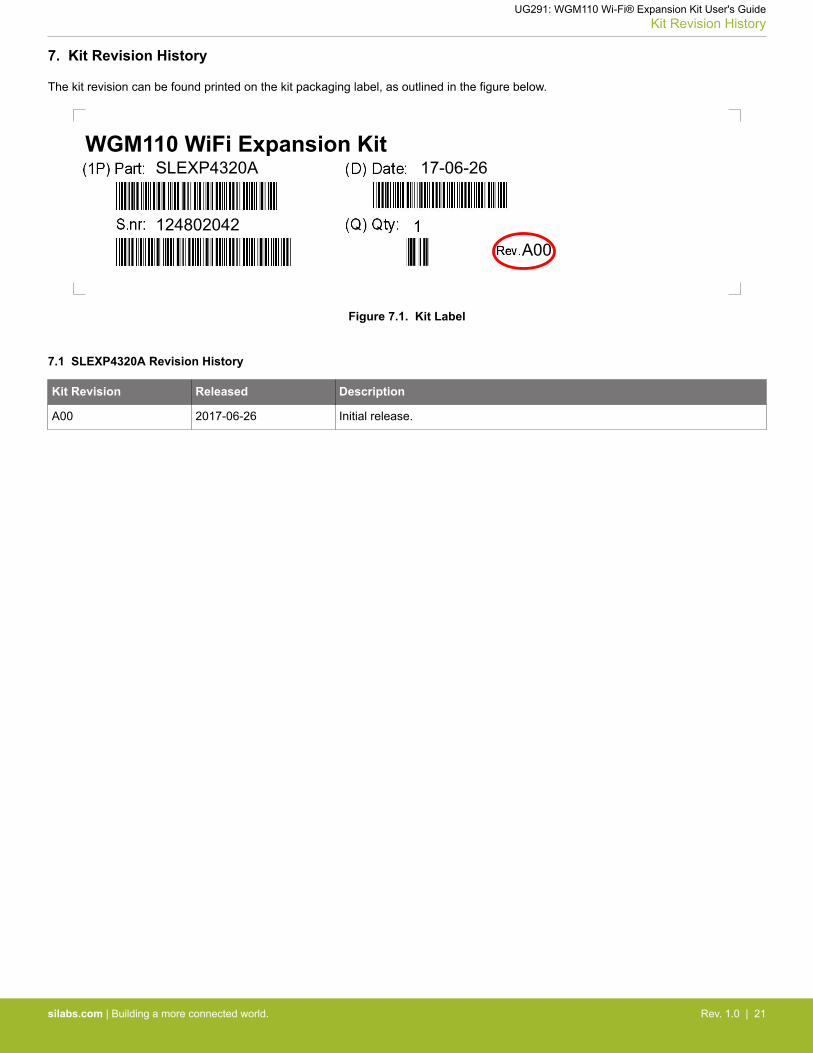
7. Kit Revision History
The kit revision can be found printed on the kit packaging label, as outlined in the figure below.
SLEXP4320AWGM110 WiFi Expansion Kit
124802042
17-06-26
A00
Figure 7.1. Kit Label
7.1 SLEXP4320A Revision History
Kit Revision Released Description
A00 2017-06-26 Initial release.
UG291: WGM110 Wi-Fi® Expansion Kit User's GuideKit Revision History
silabs.com | Building a more connected world. Rev. 1.0 | 21

8. Document Revision History
Revision 1.0
2017-06-12• Initial document revision.
UG291: WGM110 Wi-Fi® Expansion Kit User's GuideDocument Revision History
silabs.com | Building a more connected world. Rev. 1.0 | 22

http://www.silabs.com
Silicon Laboratories Inc.400 West Cesar ChavezAustin, TX 78701USA
Simplicity StudioOne-click access to MCU and wireless tools, documentation, software, source code libraries & more. Available for Windows, Mac and Linux!
IoT Portfoliowww.silabs.com/IoT
SW/HWwww.silabs.com/simplicity
Qualitywww.silabs.com/quality
Support and Communitycommunity.silabs.com
DisclaimerSilicon Labs intends to provide customers with the latest, accurate, and in-depth documentation of all peripherals and modules available for system and software implementers using or intending to use the Silicon Labs products. Characterization data, available modules and peripherals, memory sizes and memory addresses refer to each specific device, and "Typical" parameters provided can and do vary in different applications. Application examples described herein are for illustrative purposes only. Silicon Labs reserves the right to make changes without further notice and limitation to product information, specifications, and descriptions herein, and does not give warranties as to the accuracy or completeness of the included information. Silicon Labs shall have no liability for the consequences of use of the information supplied herein. This document does not imply or express copyright licenses granted hereunder to design or fabricate any integrated circuits. The products are not designed or authorized to be used within any Life Support System without the specific written consent of Silicon Labs. A "Life Support System" is any product or system intended to support or sustain life and/or health, which, if it fails, can be reasonably expected to result in significant personal injury or death. Silicon Labs products are not designed or authorized for military applications. Silicon Labs products shall under no circumstances be used in weapons of mass destruction including (but not limited to) nuclear, biological or chemical weapons, or missiles capable of delivering such weapons.
Trademark InformationSilicon Laboratories Inc.® , Silicon Laboratories®, Silicon Labs®, SiLabs® and the Silicon Labs logo®, Bluegiga®, Bluegiga Logo®, Clockbuilder®, CMEMS®, DSPLL®, EFM®, EFM32®, EFR, Ember®, Energy Micro, Energy Micro logo and combinations thereof, "the world’s most energy friendly microcontrollers", Ember®, EZLink®, EZRadio®, EZRadioPRO®, Gecko®, ISOmodem®, Micrium, Precision32®, ProSLIC®, Simplicity Studio®, SiPHY®, Telegesis, the Telegesis Logo®, USBXpress®, Zentri and others are trademarks or registered trademarks of Silicon Labs. ARM, CORTEX, Cortex-M3 and THUMB are trademarks or registered trademarks of ARM Holdings. Keil is a registered trademark of ARM Limited. All other products or brand names mentioned herein are trademarks of their respective holders.


![Adobe Photoshop PDF...Access Point LLIJtJ Dual Band Wi-Fi Access Point Wi-Fi Access Point tin] Wi-Fi 97 Wi-Fi AUDIOPHILE VIDEOPHILE nnsW01wa0QnnIWãlluunnunnvvao ñ00f-h01sQIfiðŠ](https://img.pdfslide.us/doc/110x75/5f13acbb3777f75a635fee7f/adobe-photoshop-pdf-access-point-llijtj-dual-band-wi-fi-access-point-wi-fi-access.jpg)