Embed Size (px)
Citation preview
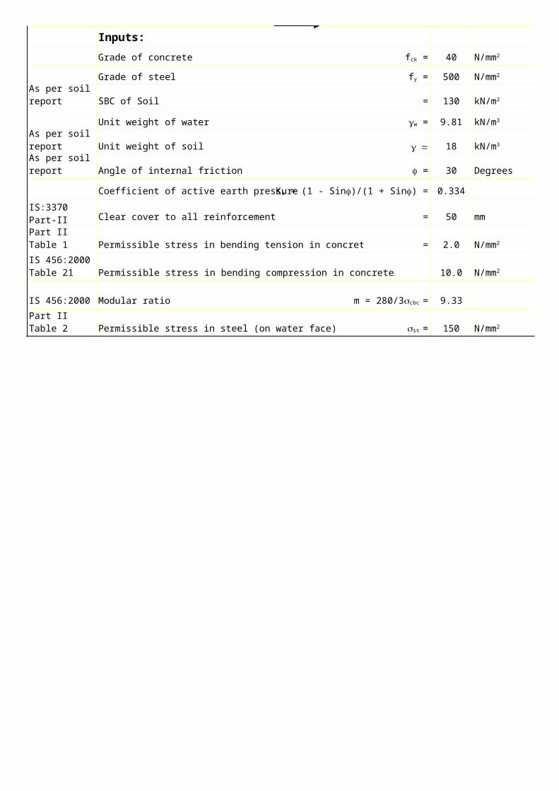
Inputs:
Grade of concrete 40
Grade of steel 500
SBC of Soil = 130
Unit weight of water 9.81
Unit weight of soil g = 18
Angle of internal friction 30 Degrees
Coefficient of active earth pressure 0.334
Clear cover to all reinforcement = 50 mm
Permissible stress in bending tension in concrete = 2.0
10.0
IS 456:2000 Modular ratio 9.33
Permissible stress in steel (on water face) 150
fck = N/mm2
fy = N/mm2
As per soil report kN/m2
gw = kN/m3
As per soil report kN/m3
As per soil report f =
Ka = (1 - Sinf)/(1 + Sinf) =
IS:3370 Part-II Clause 7.2
IS: 3370 Part II Table 1 N/mm2
IS 456:2000 Table 21 Permissible stress in bending compression in concrete scbc = N/mm2
m = 280/3scbc =
IS: 3370 Part II Table 2 sst = N/mm2
Coefficient of neutral axis 0.38
Coefficient of lever arm j =1-N/3 = 0.87
Permissible stress in steel (away from water face) 190
Coefficient of neutral axis depth 0.33
Coefficient of lever arm j =1-N/3 = 0.89
Min % of steel for 200 thick wall = 0.320 %
Min area of steel on each face for 200 thick wall = 240
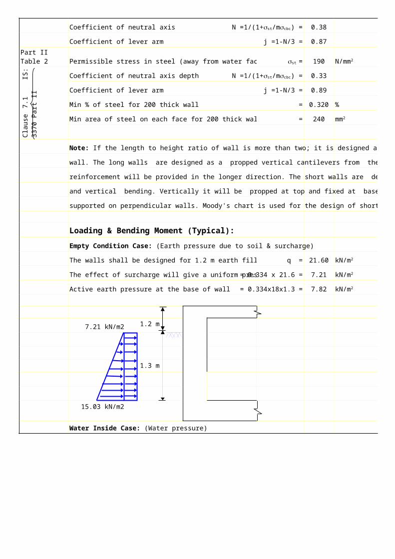
wall. The long walls are designed as a propped vertical cantilevers from the base and only minimum
reinforcement will be provided in the longer direction. The short walls are designed for both horizontal
and vertical bending. Vertically it will be propped at top and fixed at base, while horizontally it will be
supported on perpendicular walls. Moody's chart is used for the design of short walls.
Loading & Bending Moment (Typical):
The walls shall be designed for 1.2 m earth fill (surcharge) q = 21.60
The effect of surcharge will give a uniform pressure = 0.334 x 21.6 = 7.21
Active earth pressure at the base of wall = 0.334x18x1.3 = 7.82
7.21 kN/m21.2 m
1.3 m
15.03 kN/m2
N =1/(1+sst/mscbc) =
IS: 3370 Part II Table 2 sst = N/mm2
Cla
use
7.1
I
S:
33
70
P
art
II
N =1/(1+sst/mscbc) =
mm2
Note: If the length to height ratio of wall is more than two; it is designed as a long wall, else as a short
Empty Condition Case: (Earth pressure due to soil & surcharge)
kN/m2
kN/m2
kN/m2
Water Inside Case: (Water pressure)
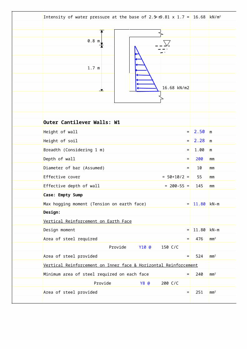
Intensity of water pressure at the base of 2.5 m high wall = 9.81 x 1.7 = 16.68
0.8 m
1.7 m
16.68 kN/m2
Outer Cantilever Walls: W1
Height of wall = 2.50 m
Height of soil = 2.28 m
Breadth (Considering 1 m) = 1.00 m
Depth of wall = 200 mm
Diameter of bar (Assumed) = 10 mm
Effective cover = 50+10/2 = 55 mm
Effective depth of wall = 200-55 = 145 mm
Case: Empty Sump
Max hogging moment (Tension on earth face) = 11.80 kN-m
Design:
Vertical Reinforcement on Earth Face
Design moment = 11.80 kN-m
Area of steel required = 476
Provide Y10 @ 150 C/C
Area of steel provided = 524
Vertical Reinforcement on Inner face & Horizontal Reinforcement
Minimum area of steel required on each face = 240
Provide Y8 @ 200 C/C
Area of steel provided = 251
kN/m2
mm2
mm2
mm2
mm2
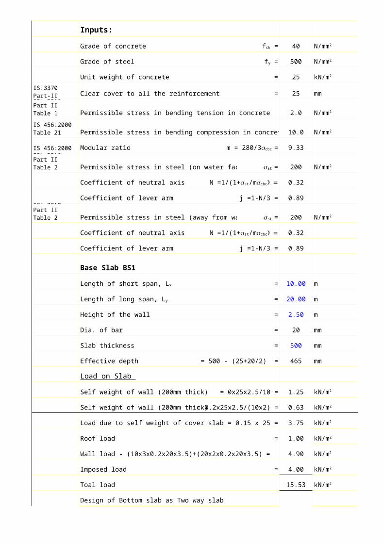
Inputs:
Grade of concrete 40
Grade of steel 500
Unit weight of concrete = 25
Clear cover to all the reinforcement = 25 mm
Permissible stress in bending tension in concrete = 2.0
10.0
IS 456:2000 Modular ratio 9.33
Permissible stress in steel (on water face) 200
Coefficient of neutral axis 0.32
Coefficient of lever arm j =1-N/3 = 0.89
Permissible stress in steel (away from water face) 200
Coefficient of neutral axis 0.32
Coefficient of lever arm j =1-N/3 = 0.89
Base Slab BS1
= 10.00 m
= 20.00 m
Height of the wall = 2.50 m
Dia. of bar = 20 mm
Slab thickness = 500 mm
Effective depth = 500 - (25+20/2) = 465 mm
Load on Slab
Self weight of wall (200mm thick) = 0x25x2.5/10 = 1.25
Self weight of wall (200mm thick) = 0.2x25x2.5/(10x2) = 0.63
Load due to self weight of cover slab = 0.15 x 25 = 3.75
Roof load = 1.00
Wall load - (10x3x0.2x20x3.5)+(20x2x0.2x20x3.5) = 4.90
Imposed load = 4.00
Toal load 15.53
Design of Bottom slab as Two way slab
fck = N/mm2
fy = N/mm2
kN/m2
IS:3370 Part-II Clause 7.2
IS: 3370 Part II Table 1 N/mm2
IS 456:2000 Table 21 Permissible stress in bending compression in concrete scbc = N/mm2
m = 280/3scbc =
IS: 3370 Part II Table 2 sst = N/mm2
N =1/(1+sst/mscbc) =
IS: 3370 Part II Table 2 sst = N/mm2
N =1/(1+sst/mscbc) =
Length of short span, Lx
Length of long span, Ly
kN/m2
kN/m2
kN/m2
kN/m2
kN/m2
kN/m2
kN/m2
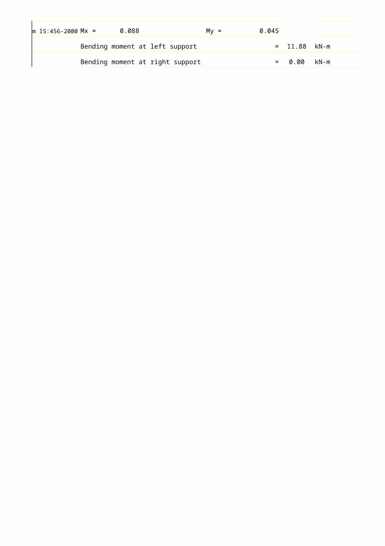
om IS:456-2000 Mx = 0.088 My = 0.045
Bending moment at left support = 11.88 kN-m
Bending moment at right support = 0.00 kN-m
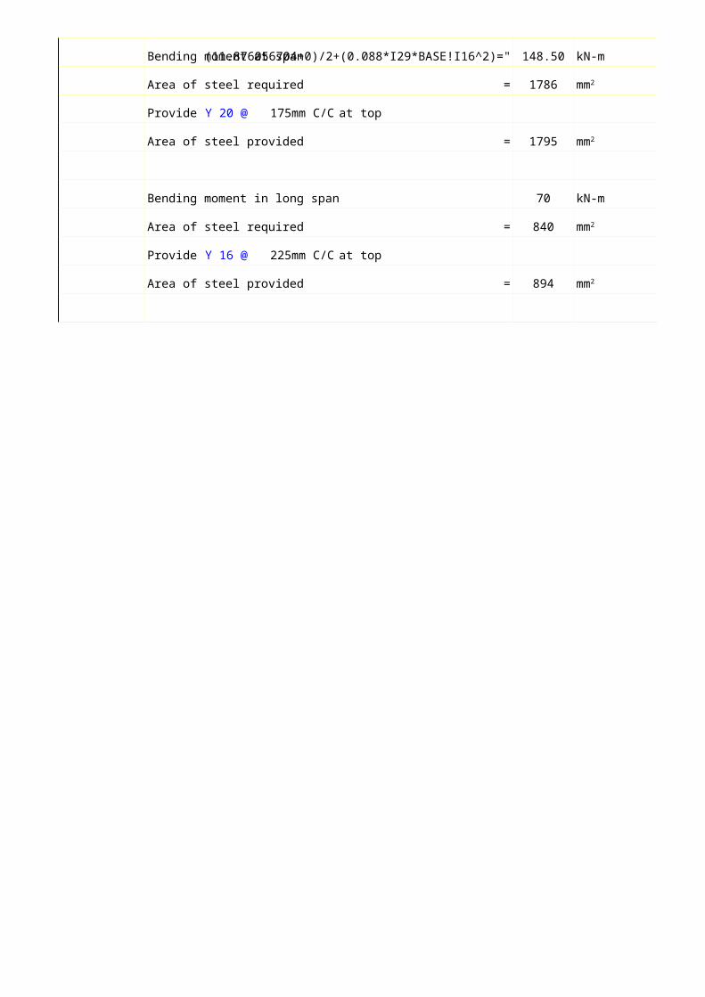
Bending moment at span=-(11.876056704+0)/2+(0.088*I29*BASE!I16^2)=" 148.50 kN-m
Area of steel required = 1786
Provide Y 20 @ 175mm C/C at top
Area of steel provided = 1795
Bending moment in long span 70 kN-m
Area of steel required = 840
Provide Y 16 @ 225mm C/C at top
Area of steel provided = 894
mm2
mm2
mm2
mm2
Design of Cover slab Center ot center of beam = 3.3 mClear span = 3 mSlab Thickness assumed = 150 mm
Design loads
Self weight of slab (0.15*25) = 3.75
Live load = 4
Finish load = 1
Total load = 8.75
Moment = 9.84375 kN-m
= 1.025391
Ast = 456Provide 10 mm dia @ 175 mm c/c at span bottom The above reinforcement is provided in support top for the flange width Provide 0.12 % as distribution steel
Ast 180Provide 8mm dia @ 200 mm c/c
Design of Tee beam
Grade of concrete 40
Grade of steel 500
Unit weight of concrete = 25Clear cover to all the reinforcement = 25 mm
Permissible stress in bending tension in concrete = 2.0
10.0
Modular ratio 9.33
Permissible stress in steel (on water face) 200
Coefficient of neutral axis 0.32Coefficient of lever arm j =1-N/3 = 0.89
Permissible stress in steel (away from water face) 200
Coefficient of neutral axis 0.32Coefficient of lever arm j =1-N/3 = 0.89
Clear span = 10 mCentre to centre of supports = 10.3 mSpacing of Tee beam ribs = 3.3 m c/c
Depth of beam required = 0.686667 mmAssumed depth including slab = 650 mmDepth of Rib = 500 mmWidth of rib = 300 mm
LoadsDead load of slab = 11.25 kN/mLive load = 12 kN/mSelf weight of Rib = 3.75 kN/mTotal load = 27 kN/m
Bending moment, M = 358.0538 KN-mShear Force, V = 139.05 kN
kN/m2
kN/m2
kN/m2
kN/m2
Mu/bd2
mm2
mm2
fck = N/mm2
fy = N/mm2
kN/m2
N/mm2
Permissible stress in bending compression in concrete scbc = N/mm2
m = 280/3scbc =
sst = N/mm2
N =1/(1+sst/mscbc) =
sst = N/mm2
N =1/(1+sst/mscbc) =
Main Steel Reinforcement
Ast = 3269.671 6.659208With 25 mm dia bars = 6.659208 NosHence provide 7 Nos of 25 dia bars at bottom Also provide 3 Nos of 16 mm dia as hanger bars
Effective Flange width is least of a) bf = 1201.717 mmb) centre to centre of ribs = 3.3 mTherefore bf requried = 1201.71 mmProvided bf = 1650 mmHence ok
Check for stresses
= m*As*(d-n)n = 174.63 mmLever arm, a = 554.29 mm
Tensile Stress in steel = 187.9454
Comp. stress in concr = 8.03098The stresses are within the safe limits
Shear stressesV = 139.05 kN
v/bd = 0.756735
= 1.75619
Design shear strength of concrete = > 0.756Hence shear reinforcements are not required. Provide nominal 2 legged stirrups of 8mm dia @ 125mm c/c
mm2
bf * n2/2
N/mm2 < 230 N/mm2
N/mm2 < 10 N/mm2
N/mm2
100 As/bwd
0.84 N/mm N/mm2