Embed Size (px)
Citation preview

© 2007. Siemens Product Lifecycle Management Software Inc. All rights reserved
Siemens PLM Software
UG ReUG Re--masteringmasteringfor Automotive Engineeringfor Automotive Engineering
1919thth October 2007October 2007

Page 2© 2007. Siemens Product Lifecycle Management Software Inc. All rights reserved
Siemens PLM Software
Modeling Issues
Re-masteringTakes time
– Release of prototype data happens soon.
Skill set not fully developed– users need time.
May not be necessary.
Page 3© 2007. Siemens Product Lifecycle Management Software Inc. All rights reserved
Siemens PLM Software
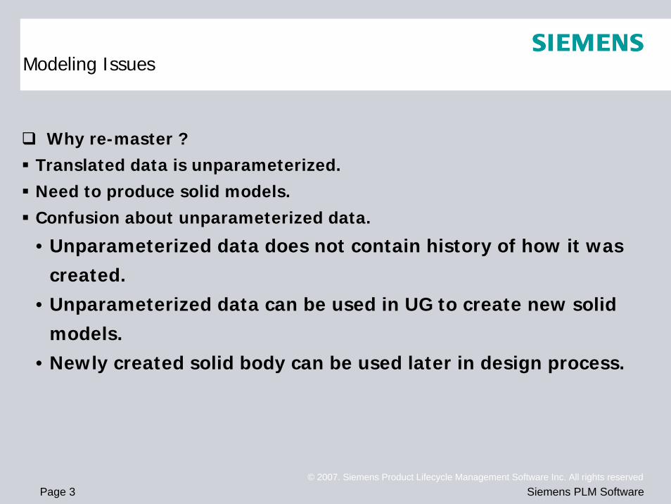
Why re-master ?Translated data is unparameterized.Need to produce solid models.Confusion about unparameterized data.
• Unparameterized data does not contain history of how it was created.
• Unparameterized data can be used in UG to create new solid models.
• Newly created solid body can be used later in design process.
Modeling Issues

Page 4© 2007. Siemens Product Lifecycle Management Software Inc. All rights reserved
Siemens PLM Software
The Overall Re-mastering Processes
ALT. 1 ALT. 2
ConceptComplete
Parametric DesignSemi-
Parametric Design
Remark
Step 1CATIA Data Conversion W/F, SUR, FAC, SOL Unparameterized
feature
Step 2-1Create Primary Sheetor Solid Bodies
Creating Sheet or SolidBodies on the basis of
CATIA surfaceParameterizedfeature
Step 2-2Primary Remodeling
Reusing CATIAMain Surfaces
Unparameterizedfeature
Step 3Evaluate Primary Sheetor Solid Bodies
Checking ModelQuality
Step 4Modify Primary Sheetor Solid Bodies
Modifying ModelProblem
Step 5Final Operations
Trimming, Sewing, Hole,Filleting, Hollowing,
Boolean Ops
ALT.1: ParameterizedFeature
ALT.2Parents: Unparameterized
FeaturesChildren: Parameterized
Features
Process
Step 6Evaluate Final Model
Checking Model QualityReporting Deviation Sheet

Page 5© 2007. Siemens Product Lifecycle Management Software Inc. All rights reserved
Siemens PLM Software
Step 1 : CATIA Data Conversion
Translated CATIA surface and solid data is high qualityOnly four CATIA elements can be translated in precise. They are W/F, SUR, FAC and SOL (per UG documentation).Currently translating surface or face data to UG.• Surface in CATIA becomes untrimmed surface in UG.• Face in CATIA becomes trimmed surface in UG.CATIA solid models should be translated to UG.
To use CATIA data after translatingSew surfaces in UG.Use “Thicken Sheet” to create solid body.
Newly created solid body can be used later in design process.
Page 6© 2007. Siemens Product Lifecycle Management Software Inc. All rights reserved
Siemens PLM Software
Step 1 : CATIA Data Conversion
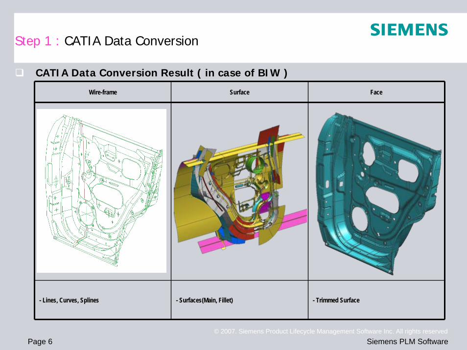
CATIA Data Conversion Result ( in case of BIW )
Wire-frame Surface Face
- Lines, Curves, Splines - Surfaces(Main, Fillet) - Trimmed Surface

Page 7© 2007. Siemens Product Lifecycle Management Software Inc. All rights reserved
Siemens PLM Software
Step 1 : CATIA Data Conversion
Data Conversion Processes( CATIA UG )
CATIA Neutral File UG Dept. Remark
Wire-frame iges Wire-frame All
Surface iges Sheet Body BodyTrim
Unparameterizedfeature
Face iges Sheet Body BodyTrim
Unparameterizedfeature
Objects
Solid step Solid Body Chassis Unparameterizedfeature
Glossary
Sheet Body - A object consisting of one or more faces not enclosing a volume. A body of zero-thickness.
Solid Body – An enclosed volume.
Unparameterized feature – A feature which cannot define and control the relationships between the features of a model.

Page 8© 2007. Siemens Product Lifecycle Management Software Inc. All rights reserved
Siemens PLM Software
Step 1 : CATIA Data Conversion
Requirements for CATIA Data ConversionFile Naming
• Observe the CATIA modeling standard(file naming) basically.• Always underscore the blank column of file name.• Do not use the special characters(ex : %, $, &, #, ?, ! …).
Layer• Observe the CATIA modeling standard basically.• Use different layers for overlapping geometry.
No Show / No Pick• Observe the CATIA modeling standard basically.• A surface which do not include a face must be deleted before data conversion.
Model Tolerance• Observe the CATIA modeling standard basically.• Do not change the default value of model tolerance in order to minimize the data conversionproblem.

Page 9© 2007. Siemens Product Lifecycle Management Software Inc. All rights reserved
Siemens PLM Software
Step 1 : CATIA Data Conversion
Requirements for CATIA Data Conversion
Surface Model• Observe the CATIA modeling standard basically.• Must be included the wire-frame, surfaces and faces in UG conversion data.• A surface which do not include a face must be deleted before data conversion.
Solid Model• Observe the CATIA modeling standard basically.• Must be included the wire-frame, surfaces, faces and solids in UG conversion data.• Do not use the ghost function of a parent management.
CATIA Model Cleaning• Delete planes, point, CST, unused details.• Delete unnecessary elements in No Show and No Pick.• Identify – Renumbering, Updating• /CLN
Axis(=Coordinate System) • All working coordinate system must be deleted and the coordinate system must be located from a absolute zero point in CATIA model before data conversion.

Page 10© 2007. Siemens Product Lifecycle Management Software Inc. All rights reserved
Siemens PLM Software
Step 2-1 : Create Primary Sheet / Solid Bodies (ALT. 1)
Extract curves from CATIA surface.Create several sheet bodies using extracted curves and CATIA wire-frame.Trim sheet bodies.
Parents : Extracted Curves from CATIA surface and CATIA wire-frame.
Parameterized feature
Children : Several Sheet Bodies of zero-thickness and trimmed bodies.
Parameterized feature

Page 11© 2007. Siemens Product Lifecycle Management Software Inc. All rights reserved
Siemens PLM Software
Step 2-2 : Primary Remodeling ( ALT. 2 )
Reuse CATIA surface data to create the primary model and do not use CATIA face data basically.Trim CATIA surface data on the basis of CATIA wire-frame. This operation is similar to the face operation at CATIA.Trimming - To shorten or extend a surface.Parents : Imported surface from CATIA
Unparameterized feature
Children : Trim body of zero-thickness
Parameterized feature
Page 12© 2007. Siemens Product Lifecycle Management Software Inc. All rights reserved
Siemens PLM Software
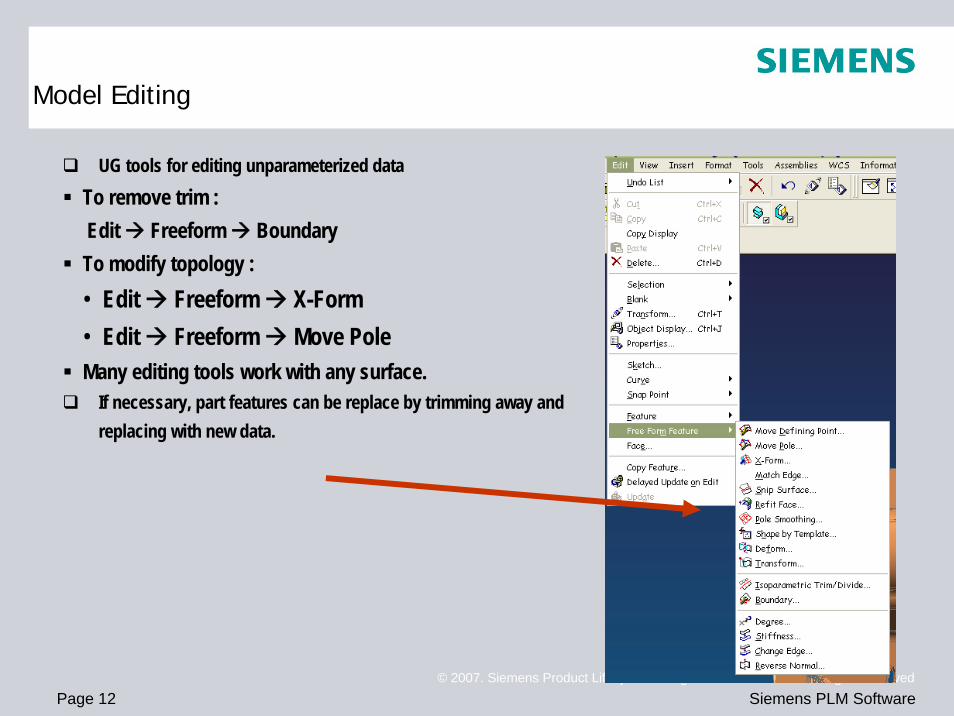
UG tools for editing unparameterized dataTo remove trim : Edit Freeform BoundaryTo modify topology : • Edit Freeform X-Form• Edit Freeform Move PoleMany editing tools work with any surface.
If necessary, part features can be replace by trimming away and replacing with new data.
Model Editing

Page 13© 2007. Siemens Product Lifecycle Management Software Inc. All rights reserved
Siemens PLM Software
Direct Modeling techniques represent extended capabilities for some of the more basic UG NX functions. Among these are face-oriented operations, constraint-based methods, blend regeneration and independence of feature history.You can use Direct Modeling functions on models that have been brought in from other CAD systems and are unparameterized.
Model Editing

Page 14© 2007. Siemens Product Lifecycle Management Software Inc. All rights reserved
Siemens PLM Software
Constrain Face - Lets you impose 3D constraints on face collections of geometric models. You can then move the faces to meet the constraints, while retaining the original topology, if possible.Resize Face - Lets you change the diameter of cylindrical or spherical faces, as well as the half-angle of conic faces, with adjacent blends recreated.Offset Region - Lets you offset a set of faces or a whole body in a single step. Adjacent blends can be optionally recreated. Faces are specified either as target faces or by region extraction methodsReplace Face - Lets you replace a set of faces with another face, with the ability to regenerate adjacent blends. You can use this option when you want to change the geometry of a face, such as to make it simpler, or to replace it with a complex surface.Local Scale - Unlike the Scale option, which lets you scale solid and sheet bodies, Local Scale lets you scale faces within a local face set.Move Region - Provides simple methods to let you locally move the faces on a body. It can be useful if you want to adjust a prototype model, and is fast and easy to use.Pattern face - Lets you make copies of a face set. It is similar to the Instance function, but is easier to use and you do not have to have a feature-based model to use it.Reblend Face - Lets you edit blend faces, regardless of their feature history. The function works with translated files and unparameterized solids, and you can use it to create a parametric feature while maintaining tangency properties.
Model Editing – Direct Modeling

Page 15© 2007. Siemens Product Lifecycle Management Software Inc. All rights reserved
Siemens PLM Software
Step 3 : Evaluate Primary Sheet / Solid Bodies
Evaluate primary sheet or solid bodies
between CATIA surface data and UG
surface data.
Examine with the naked eye.
Assess surface quality to use face analysis tools.
Radius, Reflection, Slope, DistanceUse diagnostic tools Examine Geometry.
(see the next page.)
CATIA
UG

Page 16© 2007. Siemens Product Lifecycle Management Software Inc. All rights reserved
Siemens PLM Software
Step 3 : Evaluate Primary Sheet / Solid Bodies
Math Data Quality
A certain level of data quality is required in UG datasets, to easy editing,
change and handling of these files.
The function Analysis/Examine Geometry is available in UG to analyze data
quality. It is important that the analysis is performed regularly during the
design process and not simply once at the end, as correction of
unacceptable geometry can potentially involve significant effort.

Page 17© 2007. Siemens Product Lifecycle Management Software Inc. All rights reserved
Siemens PLM Software
Step 3 : Evaluate Primary Sheet / Solid Bodies
Examine Geometry – Main menu
MandatoryChecks
Additional Tests

Page 18© 2007. Siemens Product Lifecycle Management Software Inc. All rights reserved
Siemens PLM Software
Step 3 : Evaluate Primary Sheet / Solid Bodies
Examine Geometry – Check Results
Check results are displayed
in an information Window
and in the graphics window.

Page 19© 2007. Siemens Product Lifecycle Management Software Inc. All rights reserved
Siemens PLM Software
Step 3 : Evaluate Primary Sheet / Solid Bodies
Math Data Quality
Check Items Description
Tiny Searches for all tiny bodies, faces, edges, or curve in the selected bodies or geometry.
Objects
Misaligned Checks all of the selected geometry that is close to being orthogonal with respect to the WCS, but is not exactly aligned with it.
Data Structures Checks each selected body for data structure problems, such as corruption.
Consistency Checks each selected body for inconsistencies.
Face-FaceIntersections
Checks each selected body for face-to-face intersections, and that all faces of the selected body meet each other at their edges and nowhere else.
Bodies
Sheet Boundaries Searches for all the boundaries( or gaps) in the selected bodies.
Smoothness Checks the b-surfaces(of faces that have them) to make sure the surfaces are smooth along their patch boundaries.
Self-intersection Checks for faces that self-intersect.Faces
Spikes / Cuts Searches the selected faces for possible spikes or cuts.
Smoothness Searches for all edges whose adjoining faces do not join smoothly. EdgesChecks
Tolerance Checks the tolerance of all the selected edges against the distance tolerance.

Page 20© 2007. Siemens Product Lifecycle Management Software Inc. All rights reserved
Siemens PLM Software
Step 3 : Evaluate Primary Sheet / Solid Bodies
Further Analysis Functions
Information B-Surface
Analysis Face Radius, Reflection, Slope and Distance
Analysis Deviation Checking

Page 21© 2007. Siemens Product Lifecycle Management Software Inc. All rights reserved
Siemens PLM Software
Step 4 : Modify Primary Sheet or Solid Bodies
Modify all problems in primary sheet or solid bodies.
Before After

Page 22© 2007. Siemens Product Lifecycle Management Software Inc. All rights reserved
Siemens PLM Software
Step 5 : Final Operations
Trimming, Sewing, Hole, Bead,
Filleting, Hollowing, Boolean Operations.
Create solid bodies finally.
Assemble components using mating condition.

Page 23© 2007. Siemens Product Lifecycle Management Software Inc. All rights reserved
Siemens PLM Software
Step 6 : Evaluate Final Solid Bodies
Evaluate final solid bodies between CATIA surface data and UG surface data.
Examine with the naked eye.
Assess surface quality to use face analysis tools.
Radius, Reflection, Slope, DistanceReporting Deviation Sheet.
( see next pages )

Page 24© 2007. Siemens Product Lifecycle Management Software Inc. All rights reserved
Siemens PLM Software
Part No. : 00000000
Part Name : Reinforcement – XXX XXX XXX
Deviation in the fillet merging region, near trim lines, 0.2mm
Deviation Report (Sample)

Page 25© 2007. Siemens Product Lifecycle Management Software Inc. All rights reserved
Siemens PLM Software
Trajectories are matching, but surface deviating by 0.23mm
Unable to control the fillet flow, hence the deviation of 0.21mm
Part No. : 00000000
Part Name : Panel – XXX XXX XXX
Deviation Report (Sample)

Page 26© 2007. Siemens Product Lifecycle Management Software Inc. All rights reserved
Siemens PLM Software
Guideline for UG/TcAE in Design Applications
Mandatory Requirements
3D models are to be submitted in UG data format ( created in UG ). A conversion to UG from another CAD system is not permitted.
All design must be done in UG and TcAE. A supplier can outsource work to fulfill obligations providing the design house is approved by the appropriate organization responsible.
The valid Automotive Supplier Toolkit must be available at and utilized by the supplier in the version which is demanded. Automotive Supplier Toolkit including programs and templates for DCS
General
All data sets stored ( including interim sets and data which is based on migrated data from CGS or UGMX ) by the supplier must be organized according to DCS and pass the File-Checker.

Page 27© 2007. Siemens Product Lifecycle Management Software Inc. All rights reserved
Siemens PLM Software
Guideline for UG/TcAE in Design Applications
Mandatory Requirements
All 3D design must be carried out as parametric SOLID. Any exception to this rule must be agreed by the responsible department. All parameters of a UG model must be retained in order to enable later changes.
FEATURES used during raising of a 3D model are to be unambiguous and comprehensible. Only as many FEATURES as are necessary may be used. FEATURES that provide multiple descriptions or overspecify the geometry must be avoided.
3D models based on already available data must not have been derived from non-parametric FEATURES in order to ensure a high flexibility of the model when changed are required.
3D models may not contain any SUPRESSED FEATURES.
UPDATE FEATURE must be able to be carried out. All parameters must be retained.
EXAMINE GEOMETRY must be carried out for fixed data.
TINY or LARGE OBJECTS are not allowed.
PART CLEANUP must be carried out for fixed data.
UG 3Dmodels
The BLANK level must be empty.
Page 28© 2007. Siemens Product Lifecycle Management Software Inc. All rights reserved
Siemens PLM Software
Guideline for UG/TcAE in Design Applications
Mandatory Requirements
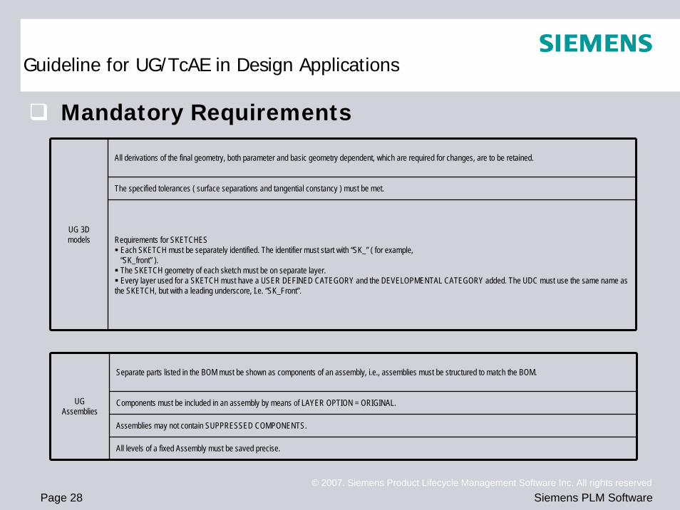
All derivations of the final geometry, both parameter and basic geometry dependent, which are required for changes, are to be retained.
The specified tolerances ( surface separations and tangential constancy ) must be met.
UG 3Dmodels Requirements for SKETCHES
Each SKETCH must be separately identified. The identifier must start with “SK_” ( for example,“SK_front” ).The SKETCH geometry of each sketch must be on separate layer.Every layer used for a SKETCH must have a USER DEFINED CATEGORY and the DEVELOPMENTAL CATEGORY added. The UDC must use the same name as
the SKETCH, but with a leading underscore, I.e. “SK_Front”.
UGAssemblies
Separate parts listed in the BOM must be shown as components of an assembly, i.e., assemblies must be structured to match the BOM.
Components must be included in an assembly by means of LAYER OPTION = ORIGINAL.
Assemblies may not contain SUPPRESSED COMPONENTS.
All levels of a fixed Assembly must be saved precise.

Page 29© 2007. Siemens Product Lifecycle Management Software Inc. All rights reserved
Siemens PLM Software
Layer & Category Assignments

Page 30© 2007. Siemens Product Lifecycle Management Software Inc. All rights reserved
Siemens PLM Software
The end
Thank you very much
for your attention !!!
Thank you very much
for your attention !!!