Embed Size (px)
Citation preview
**************************************************************************USACE / NAVFAC / AFCEC / NASA UFGS- 26 24 13 ( May 2015) Change 1 - 08/ 17 - - - - - - - - - - - - - - - - - - - - - - - - -Pr epar i ng Act i v i t y: NAVFAC
UNI FI ED FACI LI TI ES GUI DE SPECI FI CATI ONS
Ref er ences ar e i n agr eement wi t h UMRL dat ed Januar y 2020**************************************************************************
SECTION TABLE OF CONTENTS
DIVISION 26 - ELECTRICAL
SECTION 26 24 13
SWITCHBOARDS
05/15
PART 1 GENERAL
1.1 REFERENCES 1.2 RELATED REQUIREMENTS 1.3 DEFINITIONS 1.4 SUBMITTALS 1.5 QUALITY ASSURANCE 1.5.1 Product Data 1.5.2 Switchboard Drawings 1.5.3 Regulatory Requirements 1.5.4 Standard Products 1.5.4.1 Alternative Qualifications 1.5.4.2 Material and Equipment Manufacturing Date 1.6 MAINTENANCE 1.6.1 Switchboard Operation and Maintenance Data 1.6.2 Assembled Operation and Maintenance Manuals 1.6.3 Spare Parts 1.7 WARRANTY
PART 2 PRODUCTS
2.1 PRODUCT COORDINATION 2.2 SWITCHBOARD 2.2.1 Ratings 2.2.2 Construction 2.2.2.1 Enclosure 2.2.2.2 Bus Bars 2.2.2.3 Main Section 2.2.2.4 Distribution Sections 2.2.2.5 Auxiliary Sections 2.2.2.6 Handles 2.2.3 Protective Device 2.2.3.1 Power Circuit Breaker 2.2.3.2 Insulated-Case Breaker 2.2.3.3 Molded-Case Circuit Breaker 2.2.3.4 Fusible Switches
SECTION 26 24 13 Page 1
2.2.3.5 Integral Combination Breaker and Current-Limiting Fuses 2.2.4 Drawout Breakers 2.2.5 Electronic Trip Units 2.2.6 Metering 2.2.6.1 Digital Meters 2.2.6.2 Electronic Watthour Meter 2.2.6.3 Submetering 2.2.7 Transformer 2.2.8 Heaters 2.2.9 Terminal Boards 2.2.10 Wire Marking 2.3 MANUFACTURER'S NAMEPLATE 2.4 FIELD FABRICATED NAMEPLATES 2.5 SOURCE QUALITY CONTROL 2.5.1 Equipment Test Schedule 2.5.2 Switchboard Design Tests 2.5.2.1 Design Tests 2.5.2.2 Additional Design Tests 2.5.3 Switchboard Production Tests 2.5.4 Cybersecurity Equipment Certification 2.6 COORDINATED POWER SYSTEM PROTECTION 2.7 ARC FLASH WARNING LABEL 2.8 SERVICE ENTRANCE AVAILABLE FAULT CURRENT LABEL 2.9 MIMIC BUS LABELING
PART 3 EXECUTION
3.1 INSTALLATION 3.2 GROUNDING 3.2.1 Grounding Electrodes 3.2.2 Equipment Grounding 3.2.3 Connections 3.2.4 Grounding and Bonding Equipment 3.3 INSTALLATION OF EQUIPMENT AND ASSEMBLIES 3.3.1 Switchboard 3.3.2 Meters and Instrument Transformers 3.3.3 Field Applied Painting 3.3.4 Galvanizing Repair 3.3.5 Field Fabricated Nameplate Mounting 3.4 FOUNDATION FOR EQUIPMENT AND ASSEMBLIES 3.4.1 Exterior Location 3.4.2 Interior Location 3.5 FIELD QUALITY CONTROL 3.5.1 Performance of Acceptance Checks and Tests 3.5.1.1 Switchboard Assemblies 3.5.1.2 Circuit Breakers - Low Voltage - Power 3.5.1.3 Circuit Breakers 3.5.1.4 Current Transformers 3.5.1.5 Metering and Instrumentation 3.5.1.6 Grounding System 3.5.1.7 Cybersecurity Installation Certification 3.5.2 Follow-Up Verification
-- End of Section Table of Contents --
SECTION 26 24 13 Page 2
**************************************************************************USACE / NAVFAC / AFCEC / NASA UFGS- 26 24 13 ( May 2015) Change 1 - 08/ 17 - - - - - - - - - - - - - - - - - - - - - - - - -Pr epar i ng Act i v i t y: NAVFAC
UNI FI ED FACI LI TI ES GUI DE SPECI FI CATI ONS
Ref er ences ar e i n agr eement wi t h UMRL dat ed Januar y 2020**************************************************************************
SECTION 26 24 13
SWITCHBOARDS05/15
**************************************************************************NOTE: Thi s i s a new gui de speci f i cat i on t hat , i n par t , r epl aces 26 23 00, SWI TCHBOARDS AND SWI TCHGEAR. The or i gi nal gui de speci f i cat i on was separ at ed i nt o t wo speci f i cat i ons: 26 23 00, LOW- VOLTAGE SWI TCHGEAR, and 26 24 13, SWI TCHBOARDS.
Thi s gui de speci f i cat i on cover s t he r equi r ement s f or f r ee st andi ng deadf r ont swi t chboar d assembl i es r at ed 6000 amper es or l ess, 600 vol t s or l ess. Thi s gui de speci f i cat i on i s i nt ended f or al t er nat i ng cur r ent appl i cat i ons; addi t i onal edi t i ng wi l l be necessar y t o t ai l or i t f or di r ect cur r ent appl i cat i ons.
Per UFC 3- 520- 01, speci f y swi t chboar ds f or ser vi ce ent r ance equi pment when t he ser vi ce i s 1200 amper es or l ar ger , and br anch and f eeder c i r cui t s ar e combi ned si zes f r om 20 amper es up t o 800 amper es. Ut i l i ze swi t chboar ds t hr oughout t he di st r i but i on syst em wher e f eeder s ar e 1200 amper es or l ar ger . Speci f y met al - encl osed swi t chgear i n accor dance wi t h Section 26 23 00 LOW- VOLTAGE SWI TCHGEAR f or ser vi ce ent r ance equi pment onl y when t he ser vi ce i s 1200 amper es or l ar ger , and al l br anch and f eeder c i r cui t s ar e l ar ge, such as 600 amper es or 800 amper es each. Use Sect i on 26 20 00 I NTERI OR DI STRI BUTI ON SYSTEM, f or power and di st r i but i on panel boar ds r at ed l ess t han 1200 amper es.
When t he pr oposed swi t chboar d i s connect ed t o a secondar y uni t subst at i on, coor di nat e wi t h Sect i on 26 11 16 SECONDARY UNI T SUBSTATI ONS.
Thi s speci f i cat i on i s not i nt ended t o be used f or gener at or cont r ol swi t chboar ds wi t hout ext ensi ve modi f i cat i on and coor di nat i on wi t h appl i cabl e engi ne- gener at or set gui de speci f i cat i ons.
Adher e t o UFC 1-300-02 Uni f i ed Faci l i t i es Gui de Speci f i cat i ons ( UFGS) For mat St andar d when edi t i ng t hi s gui de speci f i cat i on or pr epar i ng new pr oj ect speci f i cat i on sect i ons. Edi t t hi s gui de
SECTION 26 24 13 Page 3
speci f i cat i on f or pr oj ect speci f i c r equi r ement s by addi ng, del et i ng, or r evi s i ng t ext . For br acket ed i t ems, choose appl i cabl e i t em( s) or i nser t appr opr i at e i nf or mat i on.
Remove i nf or mat i on and r equi r ement s not r equi r ed i n r espect i ve pr oj ect , whet her or not br acket s ar e present.
Comment s, suggest i ons and r ecommended changes f or t hi s gui de speci f i cat i on ar e wel come and shoul d be submi t t ed as a Criteria Change Request (CCR) .
**************************************************************************
**************************************************************************NOTE: Ver i f y t hat t he f ol l owi ng i nf or mat i on i s i ndi cat ed on t he pr oj ect dr awi ngs:
1. Si ngl e- l i ne di agr am showi ng buses and i nt er r upt i ng devi ces wi t h i nt er r upt i ng capaci t i es; cur r ent t r ansf or mer s wi t h r at i ngs; i nst r ument s and met er s r equi r ed; and descr i pt i on of i nst r ument s and meters.
2. Locat i on, space avai l abl e, ar r angement , and el evat i ons of swi t chboar ds.
3. Gr oundi ng pl an.
4. Type and number of cabl es, s i ze of conduct or s f or each power c i r cui t , and poi nt of ent r y ( t op or bottom).
5. Speci al condi t i ons, such as al t i t ude, t emper at ur e and humi di t y, exposur e t o f umes, vapor s, dust , and gases; and sei smi c r equi r ement s.
6. Ar c f l ash l abel r equi r ement s. Downl oad t he l abel f or mat at http://www.wbdg.org/ffc/dod/unified-facilities-guide-specifications-ufgs/forms-graphics-tables
7. Avai l abl e f aul t cur r ent l abel f or ser vi ce ent r ance equi pment . Downl oad t he l abel f or mat at http://www.wbdg.org/ffc/dod/unified-facilities-guide-specifications-ufgs/forms-graphics-tables
8. Locat i ons wi t h 100 per cent r at ed ci r cui t breakers.
9. Locat i ons wi t h ar c ener gy r educt i on met hods specified.
**************************************************************************
PART 1 GENERAL
1.1 REFERENCES
**************************************************************************NOTE: Thi s par agr aph i s used t o l i s t t he publ i cat i ons c i t ed i n t he t ext of t he gui de
SECTION 26 24 13 Page 4
speci f i cat i on. The publ i cat i ons ar e r ef er r ed t o i n t he t ext by basi c desi gnat i on onl y and l i s t ed i n t hi s par agr aph by or gani zat i on, desi gnat i on, dat e, and t i t l e. Use t he Ref er ence Wi zar d' s Check Ref er ence f eat ur e when you add a Ref er ence I dent i f i er ( RI D) out si de of t he Sect i on' s Ref er ence Ar t i c l e t o aut omat i cal l y pl ace t he r ef er ence i n t he Ref er ence Ar t i c l e. Al so use t he Ref er ence Wi zar d' s Check Ref er ence f eat ur e t o updat e t he i ssue dat es.
Ref er ences not used i n t he t ext wi l l aut omat i cal l y be del et ed f r om t hi s sect i on of t he pr oj ect speci f i cat i on when you choose t o r econci l e r ef er ences i n t he publ i sh pr i nt pr ocess.
**************************************************************************
The publications listed below form a part of this specification to the extent referenced. The publications are referred to in the text by the basic designation only.
AMERICAN NATIONAL STANDARDS INSTITUTE (ANSI)
ANSI C12.1 ((2014; Errata 2016) Electric Meters - Code for Electricity Metering
AMERICAN SOCIETY OF HEATING, REFRIGERATING AND AIR-CONDITIONING ENGINEERS (ASHRAE)
ASHRAE 90.1 - IP (2013) Energy Standard for Buildings Except Low-Rise Residential Buildings
ASTM INTERNATIONAL (ASTM)
ASTM A123/A123M (2017) Standard Specification for Zinc (Hot-Dip Galvanized) Coatings on Iron and Steel Products
ASTM A153/A153M (2016) Standard Specification for Zinc Coating (Hot-Dip) on Iron and Steel Hardware
ASTM A240/A240M (2018) Standard Specification for Chromium and Chromium-Nickel Stainless Steel Plate, Sheet, and Strip for Pressure Vessels and for General Applications
ASTM A653/A653M (2019) Standard Specification for Steel Sheet, Zinc-Coated (Galvanized) or Zinc-Iron Alloy-Coated (Galvannealed) by the Hot-Dip Process
ASTM A780/A780M (2009; R 2015) Standard Practice for Repair of Damaged and Uncoated Areas of Hot-Dip Galvanized Coatings
ASTM D149 (2009; R 2013) Dielectric Breakdown Voltage and Dielectric Strength of Solid
SECTION 26 24 13 Page 5
Electrical Insulating Materials at Commercial Power Frequencies
ASTM D709 (2017) Standard Specification for Laminated Thermosetting Materials
ASTM D1535 (2014; R 2018) Standard Practice for Specifying Color by the Munsell System
INSTITUTE OF ELECTRICAL AND ELECTRONICS ENGINEERS (IEEE)
IEEE 81 (2012) Guide for Measuring Earth Resistivity, Ground Impedance, and Earth Surface Potentials of a Ground System
IEEE 100 (2000; Archived) The Authoritative Dictionary of IEEE Standards Terms
IEEE C2 (2017; Errata 1-2 2017; INT 1 2017) National Electrical Safety Code
IEEE C37.13 (2015) Standard for Low-Voltage AC Power Circuit Breakers Used in Enclosures
IEEE C37.90.1 (2013) Standard for Surge Withstand Capability (SWC) Tests for Relays and Relay Systems Associated with Electric Power Apparatus
IEEE C57.12.28 (2014) Standard for Pad-Mounted Equipment - Enclosure Integrity
IEEE C57.12.29 (2014) Standard for Pad-Mounted Equipment - Enclosure Integrity for Coastal Environments
IEEE C57.13 (2016) Requirements for Instrument Transformers
INTERNATIONAL ELECTRICAL TESTING ASSOCIATION (NETA)
NETA ATS (2017; Errata 2017) Standard for Acceptance Testing Specifications for Electrical Power Equipment and Systems
NATIONAL ELECTRICAL MANUFACTURERS ASSOCIATION (NEMA)
ANSI/NEMA PB 2.1 (2013) General Instructions for Proper Handling, Installation, Operation and Maintenance of Deadfront Distribution Switchboards Rated 600 V or Less
NEMA ICS 6 (1993; R 2016) Industrial Control and Systems: Enclosures
NEMA PB 2 (2011) Deadfront Distribution Switchboards
NEMA ST 20 (2014) Dry-Type Transformers for General Applications
SECTION 26 24 13 Page 6
NATIONAL FIRE PROTECTION ASSOCIATION (NFPA)
NFPA 70 (2017; ERTA 1-2 2017; TIA 17-1; TIA 17-2; TIA 17-3; TIA 17-4; TIA 17-5; TIA 17-6; TIA 17-7; TIA 17-8; TIA 17-9; TIA 17-10; TIA 17-11; TIA 17-12; TIA 17-13; TIA 17-14; TIA 17-15; TIA 17-16; TIA 17-17 ) National Electrical Code
UNDERWRITERS LABORATORIES (UL)
UL 198M (2018) UL Standard for Mine-Duty Fuses
UL 467 (2013; Reprint Jun 2017) UL Standard for Safety Grounding and Bonding Equipment
UL 489 (2016) UL Standard for Safety Molded-Case Circuit Breakers, Molded-Case Switches and Circuit-Breaker Enclosures
UL 891 (2005; Reprint Oct 2012) Switchboards
UL 4248-1 (2017) UL Standard for Safety Fuseholders - Part 1: General Requirements
UL 4248-12 (2018) UL Standard for Safety Fuseholders - Part 12: Class R
1.2 RELATED REQUIREMENTS
**************************************************************************NOTE: I ncl ude Sect i on 26 08 00 APPARATUS I NSPECTI ON AND TESTI NG on al l pr oj ect s i nvol v i ng medi um vol t age and speci al i zed power di st r i but i on equi pment
**************************************************************************
Section 26 08 00 APPARATUS INSPECTION AND TESTING applies to this section, with the additions and modifications specified herein.
1.3 DEFINITIONS
Unless otherwise specified or indicated, electrical and electronics terms used in these specifications, and on the drawings, are as defined in IEEE 100 .
1.4 SUBMITTALS
**************************************************************************NOTE: Revi ew Submi t t al Descr i pt i on ( SD) def i ni t i ons i n Sect i on 01 33 00 SUBMI TTAL PROCEDURES and edi t t he f ol l owi ng l i s t t o r ef l ect onl y t he submi t t al s r equi r ed f or t he pr oj ect .
The Gui de Speci f i cat i on t echni cal edi t or s have desi gnat ed t hose i t ems t hat r equi r e Gover nment appr oval , due t o t hei r compl exi t y or cr i t i cal i t y, wi t h a " G. " Gener al l y, ot her submi t t al i t ems can be r evi ewed by t he Cont r act or ' s Qual i t y Cont r ol
SECTION 26 24 13 Page 7
Syst em. Onl y add a " G" t o an i t em, i f t he submi t t al i s suf f i c i ent l y i mpor t ant or compl ex i n cont ext of t he pr oj ect .
For submi t t al s r equi r i ng Gover nment appr oval on Ar my pr oj ect s, a code of up t o t hr ee char act er s wi t hi n t he submi t t al t ags may be used f ol l owi ng t he " G" desi gnat i on t o i ndi cat e t he appr ovi ng aut hor i t y. Codes f or Ar my pr oj ect s usi ng t he Resi dent Management Syst em ( RMS) ar e: " AE" f or Ar chi t ect - Engi neer ; " DO" f or Di st r i ct Of f i ce ( Engi neer i ng Di v i s i on or ot her or gani zat i on i n t he Di st r i ct Of f i ce) ; " AO" f or Ar ea Of f i ce; " RO" f or Resi dent Of f i ce; and " PO" f or Pr oj ect Of f i ce. Codes f ol l owi ng t he " G" t ypi cal l y ar e not used f or Navy, Ai r For ce, and NASA pr oj ect s.
The " S" f ol l owi ng a submi t t al i t em i ndi cat es t hat t he submi t t al i s r equi r ed f or t he Sust ai nabi l i t y eNot ebook t o f ul f i l l f eder al l y mandat ed sust ai nabl e r equi r ement s i n accor dance wi t h Sect i on 01 33 29 SUSTAI NABI LI TY REPORTI NG. Locat e t he " S" submi t t al under t he SD number t hat best descr i bes t he submi t t al i t em.
Choose t he f i r st br acket ed i t em f or Navy, Ai r For ce and NASA pr oj ect s, or choose t he second br acket ed i t em f or Ar my pr oj ect s.
**************************************************************************
Government approval is required for submittals with a "G" designation; submittals not having a "G" designation are [for Contractor QC approval.][for information only. When used, a designation following the "G" designation identifies the office that will review the submittal for the Government.] Submittals with an "S" are for inclusion in the Sustainability eNotebook, in conformance to Section 01 33 29 , SUSTAINABITY REPORTING. Submit the following in accordance with Section 01 33 00 SUBMITTAL PROCEDURES:
SD-02 Shop Drawings
Switchboard Drawings ; G[, [_____]]
SD-03 Product Data
Switchboard ; G[, [_____]]
SD-06 Test Reports
Switchboard Design Tests ; G[, [_____]]
Switchboard Production Tests ; G[, [_____]]
Acceptance Checks and Tests ; G[, [_____]]
SD-07 Certificates
Cybersecurity Equipment Certification ; G[, [_____]]
SECTION 26 24 13 Page 8
Submit certification indicating conformance with the paragraph CYBERSECURITY EQUIPMENT CERTIFICATION.
Cybersecurity Installation Certification ; G[, [_____]]
Submit certification indicating conformance with the paragraph CYBERSECURITY INSTALLATION CERTIFICATION.
SD-10 Operation and Maintenance Data
Switchboard Operation and Maintenance , Data Package 5; G[, [_____]]
SD-11 Closeout Submittals
**************************************************************************NOTE: Sel ect " Request f or Set t i ngs" bel ow i f pr ot ect i ve devi ce set t i ngs wi l l be gover nment f ur ni shed. Sel ect " Requi r ed Set t i ngs" bel ow i f pr ot ect i ve devi ce set t i ngs ar e f ur ni shed by t he Desi gner of Recor d. Coor di nat e wi t h t he per son devel opi ng t he Di v i s i on 1 Sect i ons and ensur e t hat Di v i s i on 1 Sect i ons i dent i f y t he per son r esponsi bl e f or pr ovi di ng t he f i nal pr ot ect i ve devi ce set t i ngs f or desi gn/ bui l d ver sus desi gn/ bi d/ bui l d pr oj ect s. Do not r el y on t he manuf act ur er ' s def aul t set t i ngs.
**************************************************************************
Assembled Operation and Maintenance Manuals ; G[, [_____]]
Equipment Test Schedule ; G[, [_____]]
[ Request for Settings ; G[, [_____]]
][ Required Settings ; G[, [_____]]]
**************************************************************************NOTE: NFPA 70 Ar t i c l e 110. 24 r equi r es an avai l abl e f aul t cur r ent l abel t o be appl i ed at t he ser vi ce ent r ance. Sel ect " Avai l abl e Faul t Cur r ent Label " bel ow i f t he swi t chboar d i s par t of t he ser vi ce ent r ance equi pment . Coor di nat e wi t h t he per son devel opi ng t he Di v i s i on 1 Sect i ons and ensur e t hat Di v i s i on 1 Sect i ons i dent i f y t he per son r esponsi bl e f or pr ovi di ng t he shor t c i r cui t cal cul at i on f or t he pr oj ect . Thi s may var y f or desi gn/ bui l d ver sus desi gn/ bi d/ bui l d pr oj ect s.
**************************************************************************
[ Service Entrance Available Fault Current Label ; G[, [_____]]
] 1.5 QUALITY ASSURANCE
1.5.1 Product Data
Include manufacturer's information on each submittal for each component, device and accessory provided with the switchboard including:
a. Circuit breaker type, interrupting rating, and trip devices, including available settings.
SECTION 26 24 13 Page 9
b. Manufacturer's instruction manuals and published time-current curves (in electronic format) of the main secondary breaker and largest secondary feeder device.
1.5.2 Switchboard Drawings
Include wiring diagrams and installation details of equipment indicating proposed location, layout and arrangement, control panels, accessories, piping, ductwork, and other items that must be shown to ensure a coordinated installation. Identify circuit terminals on wiring diagrams and indicate the internal wiring for each item of equipment and the interconnection between each item of equipment. Indicate on the drawings adequate clearance for operation, maintenance, and replacement of operating equipment devices. Include the nameplate data, size, and capacity on submittal. Also include applicable federal, military, industry, and technical society publication references on submittals. Include the following:
a. One-line diagram including breakers[, fuses][, current transformers, and meters].
b. Outline drawings including front elevation, section views, footprint, and overall dimensions.
c. Bus configuration including dimensions and ampere ratings of bus bars.
d. Markings and NEMA nameplate data[, including fuse information (manufacturer's name, catalog number, and ratings)].
e. Circuit breaker type, interrupting rating, and trip devices, including available settings.
f. Wiring diagrams and elementary diagrams with terminals identified, and indicating prewired interconnections between items of equipment and the interconnection between the items.
g. Manufacturer's instruction manuals and published time-current curves (in electronic format) of the main secondary breaker and largest secondary feeder device. Use this information (designer of record) to provide breaker settings that ensures protection and coordination are achieved. [For Navy installations, provide electronic format curves using SKM's Power Tools for Windows device library electronic format or EasyPower device library format depending on installation modeling software requirements.]
**************************************************************************NOTE: I f sel ect i ng pr ovi s i ons f or f ut ur e expansi on, ensur e t he f aci l i t y and r oom si ze i s adequat e f or t he addi t i onal equi pment .
**************************************************************************
[ h. Provisions for future expansion by adding switchboard sections.
] 1.5.3 Regulatory Requirements
In each of the publications referred to herein, consider the advisory provisions to be mandatory, as though the word, "shall" or "must" had been substituted for "should" wherever it appears. Interpret references in
SECTION 26 24 13 Page 10
these publications to the "authority having jurisdiction," or words of similar meaning, to mean the Contracting Officer. Provide equipment, materials, installation, and workmanship in accordance with the mandatory and advisory provisions of NFPA 70 unless more stringent requirements are specified or indicated.
1.5.4 Standard Products
Provide materials and equipment that are products of manufacturers regularly engaged in the production of such products which are of equal material, design and workmanship, and:
a. Have been in satisfactory commercial or industrial use for 2 years prior to bid opening including applications of equipment and materials under similar circumstances and of similar size.
b. Have been on sale on the commercial market through advertisements, manufacturers' catalogs, or brochures during the 2-year period.
c. Where two or more items of the same class of equipment are required, provide products of a single manufacturer; however, the component parts of the item need not be the products of the same manufacturer unless stated in this section.
1.5.4.1 Alternative Qualifications
Products having less than a 2-year field service record will be acceptable if a certified record of satisfactory field operation for not less than 6000 hours, exclusive of the manufacturers' factory or laboratory tests, is furnished.
1.5.4.2 Material and Equipment Manufacturing Date
Products manufactured more than 1 year prior to date of delivery to site are not acceptable.
1.6 MAINTENANCE
1.6.1 Switchboard Operation and Maintenance Data
Submit Operation and Maintenance Manuals in accordance with Section 01 78 23 OPERATION AND MAINTENANCE DATA.
1.6.2 Assembled Operation and Maintenance Manuals
Assemble and securely bind manuals in durable, hard covered, water resistant binders. Assemble and index the manuals in the following order with a table of contents:
a. Manufacturer's O&M information required by the paragraph SD-10, OPERATION AND MAINTENANCE DATA.
b. Catalog data required by the paragraph SD-03, PRODUCT DATA.
c. Drawings required by the paragraph SD-02, SHOP DRAWINGS.
d. Prices for spare parts and supply list.
[ e. Information on metering.
SECTION 26 24 13 Page 11
] f. Design test reports.
g. Production test reports.
[ 1.6.3 Spare Parts
**************************************************************************NOTE: Do not use t hi s par agr aph f or Navy pr oj ect s. For ot her ser vi ces, coor di nat e wi t h Cont r act i ng Of f i cer on whet her t hi s par agr aph can be i ncl uded.
Edi t as r equi r ed i f addi t i onal spar e par t s ar e r equi r ed f or a speci f i c pr oj ect .
**************************************************************************
Provide spare parts as specified below. Provide spare parts that are of the same material and workmanship, meet the same requirements, and are interchangeable with the corresponding original parts furnished.
a. Quantity 2 - Fuses of each type and size.
[ b. [_____]
] ] 1.7 WARRANTY
Provide equipment items that are supported by service organizations reasonably convenient to the equipment installation in order to render satisfactory service to the equipment on a regular and emergency basis during the warranty period of the contract.
PART 2 PRODUCTS
2.1 PRODUCT COORDINATION
Products and materials not considered to be switchboards and related accessories are specified in Section 33 71 02 UNDERGROUND ELECTRICAL DISTRIBUTION, and Section 26 20 00 INTERIOR DISTRIBUTION SYSTEM.
2.2 SWITCHBOARD
NEMA PB 2 and UL 891 .
2.2.1 Ratings
Provide equipment with the following ratings:
**************************************************************************NOTE: Sel ect " as i ndi cat ed" i f t her e ar e mul t i pl e swi t chboar ds wi t h det ai l s of each shown on dr awi ngs. Most swi t chboar ds wi l l be 4- wi r e, but mi ght be a 3- wi r e desi gn f or del t a- connect ed or ungr ounded syst ems.
**************************************************************************
a. Voltage rating: [480Y/277][208Y/120][_____] volts AC, [three-phase, [3][4]-wire][as indicated].
b. Continuous current rating of the main bus: [_____ amperes][as
SECTION 26 24 13 Page 12
indicated].
c. Short-circuit current rating: [_____ rms symmetrical amperes][as indicated].
d. UL listed and labeled[ as service entrance equipment].
2.2.2 Construction
**************************************************************************NOTE: Edi t t he sel ect i on opt i ons bel ow as needed f or t he i nt ended pr oj ect conf i gur at i on. Rear al i gned swi t chboar ds ar e l i kel y t he l owest cost desi gn pr act i ce. Fr ont and r ear al i gned swi t chboar ds pr ovi de a mor e appeal i ng i nst al l at i on. Do not speci f y r ear connect i ons i f t he swi t chboar d wi l l be i nst al l ed agai nst a wal l .
**************************************************************************
Provide the following:
a. Switchboard: consisting of one or more vertical sections[ bolted together to form a rigid assembly] and [rear][front and rear] aligned[ as indicated].
b. All circuit breakers: front accessible.
[ c. Rear aligned switchboards: front accessible load connections.
][ d. Front and rear aligned switchboards[: rear accessible load connections].
] e. Where indicated, "space for future" or "space" means to include a vertical bus provided behind a blank front cover. Where indicated, "provision for future" means full hardware provided to mount a breaker suitable for the location.
f. Completely factory engineered and assembled, including protective devices and equipment indicated with necessary interconnections, instrumentation, and control wiring.
2.2.2.1 Enclosure
**************************************************************************NOTE: Choose t he l evel of cor r osi on pr ot ect i on r equi r ed f or t he speci f i c pr oj ect l ocat i on. Most swi t chboar d pr oduct s wi l l be const r uct ed of a col d r ol l ed st eel and pai nt ed, whi ch i s adequat e f or most i ndoor l ocat i ons. Use gal vani zed st eel or st ai nl ess st eel encl osur es or bases f or out door appl i cat i ons wher e cor r osi on i s a concer n. Not al l manuf act ur er s of f er gal vani zed st eel or st ai nl ess st eel pr oduct s as a st andar d desi gn.
Sel ect I EEE C57. 12. 28 f or gal vani zed encl osur es. Sel ect I EEE C57. 12. 29 f or st ai nl ess st eel encl osur es.
**************************************************************************
Provide the following:
SECTION 26 24 13 Page 13
a. Enclosure: NEMA ICS 6 Type [3R][1][_____][as indicated][ fabricated entirely of 12 gauge ASTM A240/A240M type 304 or 304L stainless steel].
b. Enclosure: bolted together with removable bolt-on side and[ hinged] rear covers[, and sloping roof downward toward rear].
[ c. Front[ and rear] doors: provided with[ stainless steel] padlockable vault handles with a three point catch.
][ d. Bases, frames and channels of enclosure: corrosion resistant and fabricated of[ ASTM A240/A240M type 304 or 304L stainless steel][ or][ galvanized steel].
] e. Base: includes any part of enclosure that is within 75 mm 3 inches of concrete pad.
[ f. Galvanized steel: ASTM A123/A123M , ASTM A653/A653M G90 coating, and ASTM A153/A153M , as applicable. Galvanize after fabrication where practicable.
] g. Paint color: ASTM D1535 light gray No. 61 or No. 49 over rust inhibitor.
[ h. Paint coating system: comply with[ IEEE C57.12.28 for galvanized steel][ and][ IEEE C57.12.29 for stainless steel].
] 2.2.2.2 Bus Bars
**************************************************************************NOTE: Use copper wi t h s i l ver - pl at ed cont act sur f aces i n ext er i or or damp l ocat i ons or f or heavy mot or loads.
Del et e t he neut r al bus br acket ed opt i on i f a 3- wi r e syst em was sel ect ed.
Onl y choose t he br acket ed opt i on r equi r i ng i nsul at i onon t he bus bar s f or out door l ocat i ons wi t h a hi gh concent r at i on of ai r bor ne cont ami nant s. Choose t hi s opt i on pr i mar i l y f or cor r osi ve and hi gh humi di t y appl i cat i ons as def i ned i n UFC 3- 501- 01. Most manuf act ur er s wi l l t ape wr ap r at her t han appl y an i nsul at i ng s l eeve f or l ow vol t age equi pment .
**************************************************************************
Provide the following:
a. Bus bars: [copper with silver-plated contact surfaces][ or][aluminum with tin-plated contact surfaces].
(1) Phase bus bars: [uninsulated][insulated with a tape wrap or insulating sleeve providing a minimum breakdown voltage of 16,000 volts per ASTM D149].
(2) Neutral bus: rated [100][_____] percent of the main bus continuous current rating[ as indicated].
b. Make bus connections and joints with hardened steel bolts.
SECTION 26 24 13 Page 14
c. Main-bus (through bus): rated at the full ampacity of the main throughout the switchboard.
d. Minimum 6.35 mm by 50.8 mm one-quarter by 2 inch copper ground bus secured to each vertical section along the entire length of the switchboard.
2.2.2.3 Main Section
**************************************************************************NOTE: Sel ect f r om t he opt i ons bel ow t he conf i gur at i on t o be speci f i ed. Ref er t o UFC 3- 520- 01 f or al l owed conf i gur at i ons.
Si mpl er swi t chboar ds wi l l of t en have a s i ngl e sect i on t hat cont ai ns t he mai n c i r cui t br eaker and br anch ci r cui t br eaker s, r ef er r ed t o her e as a Combi nat i on Sect i on. Lar ger swi t chboar ds can have mul t i pl e sect i ons i nvol v i ng a mai n sect i on, one or mor e di st r i but i on sect i ons, and one or mor e auxi l i ar y sect i ons.
Low- vol t age power c i r cui t br eaker s ar e not nor mal l y r equi r ed f or swi t chboar d appl i cat i ons. Ut i l i t y t r ansf or mer compar t ment s ar e r ar el y used and wi l l r equi r e addi t i onal r evi ew i f t hi s br acket ed opt i on i s sel ect ed.
**************************************************************************
Provide the main section consisting of[a combination section with[ molded-case circuit breakers] for the[ main and] branch devices as indicated][ main lugs only][ an individually mounted [fixed][ drawout][ air power circuit breaker[ with current-limiting fuses]][ insulated-case circuit breaker][ molded-case circuit breaker]][ and utility transformer compartment].
[ 2.2.2.4 Distribution Sections
**************************************************************************NOTE: Sel ect di st r i but i on sect i ons as an opt i on i f t he mai n sect i on i s not a combi nat i on sect i on t hat i ncl udes mai n and br anch ci r cui t br eaker s.
**************************************************************************
Provide the distribution section[s] consisting of[ [individually mounted,][drawout,]][ air power circuit breakers[ with current-limiting fuses]][ insulated-case circuit breakers][ molded-case circuit breakers][ and utility transformer compartments] as indicated.
][ 2.2.2.5 Auxiliary Sections
Provide auxiliary sections consisting of indicated[ instruments,][ metering equipment,][ control equipment,][ transformer,][ and][ current transformer compartments] as indicated.
][ 2.2.2.6 Handles
Provide handles for individually mounted devices of the same design and
SECTION 26 24 13 Page 15
method of external operation. Label handles prominently to indicate device ampere rating, color coded for device type. Identify ON-OFF indication by handle position and by prominent marking.
] 2.2.3 Protective Device
**************************************************************************NOTE: Swi t chboar d shoul d be pl aced wher e t he ambi ent t emper at ur e i s l ess t han 40 deg. C. However , shoul d t he ambi ent t emper at ur e be expect ed t o exceed 40 Deg. C, t he desi gner must r equi r e a speci al cal i br at i on f or t he c i r cui t br eaker s and conf i r m t he equi pment r at i ngs.
Pr ovi de gr ound f aul t pr ot ect i on of equi pment f or sol i dl y gr ounded wye el ect r i cal ser vi ces of mor e t han 150 vol t s t o gr ound f or each ser vi ce di sconnect r at ed 1000 amper es or mor e i n accor dance wi t h NFPA 70.
I f 48 Vdc or 125 Vdc el ect r i cal l y oper at ed ci r cui t br eaker s ar e r equi r ed, t he appr opr i at e DC cont r ol power suppl y i nf or mat i on must be added t o t he specification.
**************************************************************************
Provide[ main and] branch protective devices as indicated.
[ 2.2.3.1 Power Circuit Breaker
**************************************************************************NOTE: Low- vol t age power c i r cui t br eaker s can be i nst al l ed i n l ar ger swi t chboar ds, but ar e not nor mal l y r equi r ed f or swi t chboar d appl i cat i ons. I f power c i r cui t br eaker s ar e sel ect ed, coor di nat e t he r at i ngs and pr ot ect i ve devi ce set t i ngs wi t h t he r at i ngs of t he swi t chboar d.
**************************************************************************
Provide the following:
a. IEEE C37.13 . [120 Vac][ electrically][ manually] operated [stationary][drawout], [unfused][fused], low-voltage power circuit breaker with a short-circuit current rating[ of [_____] rms amperes symmetrical][ as indicated] at [_____] volts.
b. Breaker frame size: [ as indicated][ [_____] amperes].
[c. Equip electrically operated breakers with motor-charged, stored-energy closing mechanism to permit rapid and safe closing of the breaker against fault currents within the short time rating of the breaker, independent of the operator's strength or effort in closing the handle.
] ][ 2.2.3.2 Insulated-Case Breaker
Provide the following:
**************************************************************************
SECTION 26 24 13 Page 16
NOTE: El ect r i cal l y oper at ed i nsul at ed- case ci r cui t br eaker s ar e r ar el y used and woul d be accompl i shed by an accessor y.
I f 100 per cent c i r cui t br eaker s ar e ut i l i zed i n t he desi gn, sel ect t he 100 per cent r at ed ci r cui t br eaker opt i on bel ow and i ndi cat e t he speci f i c l ocat i ons on t he dr awi ngs.
**************************************************************************
a. UL 489 . UL listed and labeled,[ 100 percent rated main breaker][ standard rated branch breakers],[ electrically] [manually] operated, low voltage, insulated-case circuit breaker, with a short-circuit current rating[ of [_____] rms symmetrical amperes][ as indicated] at [_____] volts.
b. Breaker frame size: [ [_____] amperes][ as indicated].
c. Series rated circuit breakers are unacceptable.
][ 2.2.3.3 Molded-Case Circuit Breaker
Provide the following:
**************************************************************************NOTE: I f 100 per cent c i r cui t br eaker s ar e ut i l i zed i n t he desi gn, sel ect t he 100 per cent r at ed ci r cui t br eaker opt i on bel ow and i ndi cat e t he speci f i c l ocat i ons on t he dr awi ngs.
**************************************************************************
a. UL 489 . UL listed and labeled,[ 100 percent rated main breaker][ standard rated branch breakers],[ electrically][ manually] operated, low voltage molded-case circuit breaker, with a short-circuit current rating of[ [_____] rms symmetrical amperes][ as indicated] at [_____] volts.
b. Breaker frame size: [ [_____] amperes][ as indicated].
c. Series rated circuit breakers are unacceptable.
][ 2.2.3.4 Fusible Switches
**************************************************************************NOTE: Do not use f usi bl e over cur r ent devi ces except when necessar y t o compl y wi t h NFPA 70 r equi r ement s f or sel ect i ve coor di nat i on. Fusi bl e swi t ches ar e pr ohi bi t ed by UFC 3- 520- 01 and wer e not l i s t ed as an opt i on above. Thei r use wi l l r equi r e appr oval by t he aut hor i t y havi ng j ur i sdi ct i on t o al l ow t hei r use i n swi t chboar ds.
I f speci f i ed, sel ect UL 4248- 1 f usehol der s f or Cl ass J or L f uses. Sel ect UL 4248- 12 f or Cl ass R f uses.
**************************************************************************
Provide the following:
a. Fusible Switches: quick-make, quick-break, hinged-door type.
SECTION 26 24 13 Page 17
[ b. Switches serving as motor disconnects: horsepower rated.
] c. Fuses: current-limiting cartridge type conforming to[ UL 198M , Class J for 0 to 600 amperes and Class L for 601 to 6000 amperes][ UL 198M , Class [RK1][RK5] for 0 to 600 amperes].
d. Fuseholders: [ UL 4248-1 ][ UL 4248-12 ].
][ 2.2.3.5 Integral Combination Breaker and Current-Limiting Fuses
**************************************************************************NOTE: Cur r ent - l i mi t i ng f uses shoul d onl y be needed i f t he avai l abl e f aul t cur r ent exceeds t he ci r cui t br eaker shor t c i r cui t r at i ng. Thi s opt i on wi l l not t ypi cal l y be sel ect ed.
**************************************************************************
Provide the following:
a. UL 489 .
b. Integral combination molded-case circuit breaker and current-limiting fuses:[ as indicated][ rated [_____] amperes] with a minimum short-circuit-current rating equal to the short-circuit-current rating of the switchboard in which the circuit breaker will be mounted.
c. Series rated circuit breakers are unacceptable.
d. Coordination of overcurrent devices of the circuit breaker and current-limiting fuses: for overloads or fault currents of relatively low value, the overcurrent device of the breaker operates to clear the fault. The current-limiting fuses operate to clear the fault for high magnitude short circuits above a predetermined value[ crossover point].
e. Housing for the current-limiting fuses: an individual molding readily removable from the front and located at the load side of the circuit breaker. If the fuse housing is removed, a blown fuse is readily evident by means of a visible indicator.
f. Removal of fuse housing causes the breaker contacts to open, and the breaker contacts can not close with the fuse housing removed. The fuse housing can not be inserted with a blown fuse or with one fuse missing. The blowing of any of the fuses causes the circuit breaker contacts to open.
] [ 2.2.4 Drawout Breakers
**************************************************************************NOTE: Det er mi ne whi ch ci r cui t br eaker s shoul d be equi pped wi t h dr awout mechani sms.
**************************************************************************
Provide drawout breakers[ as indicated][_____]. Equip drawout breakers with disconnecting contacts, wheels, and interlocks for drawout application. Provide main, auxiliary, and control disconnecting contacts with silver-plated, multifinger, positive pressure, self-aligning type. Provide each drawout breaker with four-position operation with each position clearly identified by an indicator on the circuit breaker front
SECTION 26 24 13 Page 18
panel as follows.
a. Connected Position: Primary and secondary contacts are fully engaged. Breaker must be tripped before racking into or out of position.
b. Test Position: Primary contacts are disconnected but secondary contacts remain fully engaged. This position allows complete test and operation of the breaker without energizing the primary circuit.
c. Disconnected Position: Primary and secondary contacts are disconnected.
d. Withdrawn (Removed) Position: Places breaker completely out of compartment, ready for removal. Removal of the breaker actuates assembly that isolates the primary stabs.
] 2.2.5 Electronic Trip Units
**************************************************************************NOTE: Swi t chboar ds can have a var i et y of c i r cui t br eaker s i zes. Det er mi ne whi ch ci r cui t br eaker s or ot her pr ot ect i ve devi ces shoul d have el ect r oni c t r i p uni t s and edi t t he opt i ons bel ow accor di ngl y. Smal l er c i r cui t br eaker s wi l l t ypi cal l y have t her mal - magnet i c t r i p uni t s.
**************************************************************************
Equip[ main and][ distribution] breakers[ as indicated] with a solid-state tripping system consisting of three current sensors and a microprocessor-based trip unit that provides true rms sensing adjustable time-current circuit protection. Include the following:
a. Current sensors ampere rating: [ as indicated][ [_____] amperes][ the same as the breaker frame rating].
b. Trip unit ampere rating: [ as indicated][ [_____] amperes].
[ c. Ground fault protection: [ as indicated][ zero sequence sensing][ residual type sensing].
][ d. Electronic trip units: provide additional features[ as indicated]:]
**************************************************************************NOTE: I n t he i t ems bel ow, choose t he br acket ed i t em " mai n" when t he i t em onl y appl i es t o t he mai n breaker.
Pr ovi de gr ound f aul t pr ot ect i on of equi pment f or sol i dl y gr ounded wye el ect r i cal ser vi ces of mor e t han 150 vol t s t o gr ound f or each ser vi ce di sconnect r at ed 1000 amper es or mor e i n accor dance wi t h NFPA 70.
NFPA 70 r equi r es ar c ener gy r educt i on wher e t he hi ghest cont i nuous cur r ent t r i p set t i ng f or whi ch t he act ual over cur r ent devi ce i nst al l ed i n a c i r cui t br eaker i s r at ed or can be adj ust ed t o 1200 amper es or hi gher . The opt i on i dent i f i ed bel ow i s based on
SECTION 26 24 13 Page 19
an ener gy- r educi ng mai nt enance swi t ch. Add t he addi t i onal appr opr i at e i nf or mat i on i f ot her met hods such as di f f er ent i al r el ayi ng or an act i ve ar c f l ash mi t i gat i on syst em ar e i ncl uded. I dent i f y l ocat i ons of al t er nat e ar c ener gy r educt i on met hods i n t he design.
**************************************************************************
[ (1) [Indicated ]Breakers: include long delay pick-up and time settings, and LED indication of cause of circuit breaker trip.
][ (2) Main breakers: include[ short delay pick-up and time settings][ and][, instantaneous settings][ and][ ground fault settings][ as indicated].
][ (3) Distribution breakers: include[ short delay pick-up and time settings][, instantaneous settings][, and ground fault settings][ as indicated].
][ (4) [Main ]Breakers: include a digital display for phase and ground current.
][ (5) [Main ]Breakers: include a digital display for watts, vars, VA, kWh, kvarh, and kVAh.
][ (6) [Main ]Breakers: include a digital display for phase voltage, and percent THD voltage and current.
][ (7) [Main ]Breakers: include provisions for communication via a network twisted pair cable for remote monitoring and control. Provide the following communications protocol:[DNP3][Modbus][IEC 61850].
][ (8) For electronic trip units that are rated for or can be adjusted to 1,200 amperes or higher, provide arc energy reduction capability with an energy-reducing maintenance switch with local status indicator.
] [ 2.2.6 Metering
**************************************************************************NOTE: When Sect i on 23 09 00 I NSTRUMENTATI ON AND CONTROL FOR HVAC i s used, coor di nat e met er requirements.
**************************************************************************
[ 2.2.6.1 Digital Meters
**************************************************************************NOTE: Di gi t al met er i ng i ncor por at es newer t echnol ogy and pr ovi des addi t i onal i nf or mat i on, of t en wi t hout addi t i onal cost . A cont r ol power t r ansf or mer ( 115 V or 130 V) i s usual l y r equi r ed wi t h t hi s t ype of metering.
Di gi t al met er s ar e cont i nual l y i mpr ovi ng. The di spl ay capabi l i t y can be a s i mpl e di spl ay of numer i cal val ues or a mor e sophi st i cat ed di spl ay showi ng wavef or ms. Over - speci f i cat i on of t he met er
SECTION 26 24 13 Page 20
physi cal or sof t war e char act er i st i cs wi l l l i kel y r esul t i n speci f i cat i on of an ol der obsol et e met er .
**************************************************************************
IEEE C37.90.1 for surge withstand. Provide true rms, plus/minus one percent accuracy, programmable, microprocessor-based meter enclosed in a sealed case with the following features.
a. Display capability:
[ (1) Multi-Function Meter: Display a selected phase to neutral voltage, phase to phase voltage, percent phase to neutral voltage THD, percent phase to phase voltage THD; a selected phase current, neutral current, percent phase current THD, percent neutral current; selected total PF, kW, KVA, kVAR, FREQ, kVAh, kWh. Detected alarm conditions include over/under current, over/under voltage, over/under KVA, over/under frequency, over/under selected PF/kVAR, voltage phase reversal, voltage imbalance, reverse power, over percent THD. Include a Form C KYZ pulse output relay on the meter.
][ (2) Power Meter: Display Watts, VARs, and selected KVA/PF. Detected alarm conditions include over/under KVA, over/under PF, over/under VARs, over/under reverse power.
][ (3) Volt Meter: Provide capability to be selectable between display of the three phases of phase to neutral voltages and display of the three phases of the phase to phase voltages. Detected alarm conditions include over/under voltage, over/under voltage imbalance, over percent THD.
][ (4) Ammeter: Display phase A, B, and C currents. Detected alarm conditions include over/under current, over percent THD.
][ (5) Digital Watthour Meter: Provide a single selectable display for watts, total kilowatt hours (kWh) and watt demand (Wd). Include a Form C KYZ pulse output relay on the meter.
] b. Design meters to accept[ input from standard 5A secondary instrument transformers][ and][ direct voltage monitoring range to [300][600] volts, phase to phase].
c. Provide programming via a front panel display and a communication interface accessible by a computer.
d. Provide password secured programming stored in non-volatile EEPROM memory.
e. Provide digital communications in a Modbus [RTU] protocol via a [RS232C][RS485] serial port[ and an independently addressable [RS232C][RS485] serial port].
f. Provide meter that calculates and stores average max/min demand values with time and date for all readings based on a user selectable sliding window averaging period.
g. Provide meter with programmable hi/low set limits with two Form C dry contact relays when exceeding alarm conditions.
SECTION 26 24 13 Page 21
[ h. Provide meter with a display of Total Harmonic Distortion (THD) measurement to a minimum of the thirty-first order.
][ i. Include historical trend logging capability with the ability to store up to 100,000 data points with intervals of 1 second to 180 minutes. Provide a unit that can store and time stamp up to 1000 programmable triggered conditions.
][ j. Provide event waveform recording triggered by the rms of 2 cycles of voltage or current exceeding programmable set points. Store waveforms for all 6 channels of voltage and current for a minimum of 10 cycles prior to the event and 50 cycles past the event.
] ][ 2.2.6.2 Electronic Watthour Meter
**************************************************************************NOTE: For t he Ai r For ce, use Sect i on 26 27 13. 10 30 ELECTRI C METERS.
For t he Navy, use Sect i on 26 27 14. 00 20 ELECTRI CI TY METERING.
For t he Ar my, coor di nat e met er r equi r ement s i n accor dance wi t h Engi neer i ng and Const r uct i on Bul l et i n ECB 2015- 2, Advanced Met er i ng and Connectivity.
**************************************************************************
[ Provide as specified in Section [ 26 27 14.00 20 ELECTRICITY METERING][26 27 13.10 30 ELECTRIC METERS].
][ ANSI C12.1 . Provide a switchboard style electronic programmable watthour meter, semi-flush mounted, as indicated. Meter can be either programmed at the factory or programmed in the field. Turn field programming device over to the Contracting Officer at completion of project. Coordinate meter to system requirements.
a. Design: Provide meter designed for use on a 3-phase, 4-wire, [208Y/120][480Y/277] volt system with 3 current transformers. Include necessary KYZ pulse initiation hardware for Energy Monitoring and Control System (EMCS).
b. Coordination: Provide meter coordinated with ratios of current transformers and transformer secondary voltage.
c. Class: 20. Accuracy: plus or minus 1.0 percent. Finish: Class II.
d. Kilowatt-hour Register: five digit electronic programmable type.
e. Demand Register:
(1) Provide solid state.
(2) Meter reading multiplier: Indicate multiplier on the meter face.
(3) Demand interval length: programmed for [15][30][60] minutes with rolling demand up to six subintervals per interval.
f. Meter fusing: Provide a fuse block mounted in the metering compartment
SECTION 26 24 13 Page 22
containing one fuse per phase to protect the voltage input to the watthour meter. Size fuses as recommended by the meter manufacturer.
g. Provide meter with a communications port, RS485, with Modbus RTU serial or Ethernet, Modbus-TCP communications.
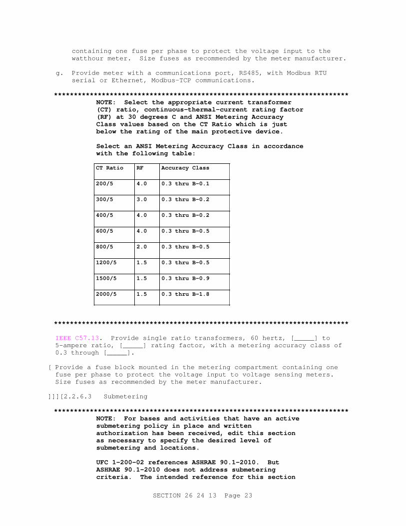
**************************************************************************NOTE: Sel ect t he appr opr i at e cur r ent t r ansf or mer ( CT) r at i o, cont i nuous- t her mal - cur r ent r at i ng f act or ( RF) at 30 degr ees C and ANSI Met er i ng Accur acy Cl ass val ues based on t he CT Rat i o whi ch i s j ust bel ow t he r at i ng of t he mai n pr ot ect i ve devi ce.
Sel ect an ANSI Met er i ng Accur acy Cl ass i n accor dance wi t h t he f ol l owi ng t abl e:
CT Rat i o RF Accur acy Cl ass
200/5 4.0 0. 3 t hr u B- 0. 1
300/5 3.0 0. 3 t hr u B- 0. 2
400/5 4.0 0. 3 t hr u B- 0. 2
600/5 4.0 0. 3 t hr u B- 0. 5
800/5 2.0 0. 3 t hr u B- 0. 5
1200/5 1.5 0. 3 t hr u B- 0. 5
1500/5 1.5 0. 3 t hr u B- 0. 9
2000/5 1.5 0. 3 t hr u B- 1. 8
**************************************************************************
IEEE C57.13 . Provide single ratio transformers, 60 hertz, [_____] to 5-ampere ratio, [_____] rating factor, with a metering accuracy class of 0.3 through [_____].
[ Provide a fuse block mounted in the metering compartment containing one fuse per phase to protect the voltage input to voltage sensing meters. Size fuses as recommended by the meter manufacturer.
]] ][ 2.2.6.3 Submetering
**************************************************************************NOTE: For bases and act i v i t i es t hat have an act i ve submet er i ng pol i cy i n pl ace and wr i t t en aut hor i zat i on has been r ecei ved, edi t t hi s sect i on as necessar y t o speci f y t he desi r ed l evel of submet er i ng and l ocat i ons.
UFC 1- 200- 02 r ef er ences ASHRAE 90. 1- 2010. But ASHRAE 90. 1- 2010 does not addr ess submet er i ng cr i t er i a. The i nt ended r ef er ence f or t hi s sect i on
SECTION 26 24 13 Page 23
i s ASHRAE 90. 1- 2013, whi ch does addr ess submet er i ng criteria.
I f submet er i ng i s sel ect ed as an opt i on, coor di nat e r ef er ences t o ASHRAE 90. 1 wi t h t he l ead per son edi t i ng t he Di v i s i on 1 Sect i ons. Typi cal l y, r ef er ences t o ASHRAE 90. 1 i n t hi s Sect i on wi l l be t o t he 2013 edi t i on, wher eas r ef er ences t o ASHRAE 90. 1 i n ot her Sect i ons wi l l be t o t he 2010 edi t i on.
**************************************************************************
ASHRAE 90.1 - IP . Provide submetering for [_____].
] ][ 2.2.7 Transformer
**************************************************************************NOTE: Coor di nat e wi t h Sect i on 26 20 00 I NTERI OR DI STRI BUTI ON SYSTEM, when t r ansf or mer sect i on i s pr ovi ded.
**************************************************************************
Provide transformer section in switchboard in accordance with UL 891 and as indicated. Provide the transformer and section that is suitable for the installation.[ Test transformers greater than 10 kVA in accordance with UL 891 .] Provide a transformer conforming to the requirements of Section 26 20 00 INTERIOR DISTRIBUTION SYSTEM.
][ 2.2.8 Heaters
**************************************************************************NOTE: Sel ect t he heat er opt i on i f t he swi t chboar d wi l l be i nst al l ed i n a non- envi r onment al l y cont r ol l ed ar ea.
**************************************************************************
Provide 120-volt heaters in each switchboard section. Provide heaters of sufficient capacity to control moisture condensation in the section, 250 watts minimum, and controlled by a thermostat[ and humidistat] located in the section. Provide industrial type thermostat, high limit, to maintain sections within the range of 15 to 32 degrees C 60 to 90 degrees F .[ Provide humidistat with a range of 30 to 60 percent relative humidity.] Obtain supply voltage for the heaters from a control power transformer within the switchboard. If heater voltage is different than switchboard voltage, provide transformer rated to carry 125 percent of heater full load rating. Provide transformer with a 220 degrees C insulation system with a temperature rise not exceeding 115 degrees C and conforming to NEMA ST 20 .[ Energize electric heaters in switchboard assemblies while the equipment is in storage or in place prior to being placed in service. Provide method for easy connection of heater to external power source. Provide temporary, reliable external power source if commercial power at rated voltage is not available on site.]
] 2.2.9 Terminal Boards
Provide with engraved plastic terminal strips and screw type terminals for external wiring between components and for internal wiring between removable assemblies. Provide short-circuiting type terminal boards associated with current transformer. Terminate conductors for current transformers with ring-tongue lugs. Provide terminal board identification
SECTION 26 24 13 Page 24
that is identical in similar units. Provide color coded external wiring that is color coded consistently for similar terminal boards.
2.2.10 Wire Marking
Mark control and metering conductors at each end. Provide factory installed, white, plastic tubing, heat stamped with black block type letters on factory-installed wiring. On field-installed wiring, provide white, preprinted, polyvinyl chloride (PVC) sleeves, heat stamped with black block type letters. Provide a single letter or number on each sleeve, elliptically shaped to securely grip the wire, and keyed in such a manner to ensure alignment with adjacent sleeves. Provide specific wire markings using the appropriate combination of individual sleeves. Indicate on each wire marker the device or equipment, including specific terminal number to which the remote end of the wire is attached.
2.3 MANUFACTURER'S NAMEPLATE
Provide a nameplate on each item of equipment bearing the manufacturer's name, address, model number, and serial number securely affixed in a conspicuous place; the nameplate of the distributing agent is not acceptable. This nameplate and method of attachment may be the manufacturer's standard if it contains the required information.
2.4 FIELD FABRICATED NAMEPLATES
**************************************************************************NOTE: Use t he br acket ed sent ence t o speci f y l abel s f or swi t chboar ds wher e emer gency br eaker s ar e l ocat ed wi t hi n t he swi t chboar d. Pr ovi de not e on t he dr awi ngs t o i ndi cat e wher e r ed l abel s ar e r equi r ed.
**************************************************************************
ASTM D709. Provide laminated plastic nameplates for each switchboard, equipment enclosure, relay, switch, and device; as specified in this section or as indicated on the drawings. Identify on each nameplate inscription the function and, when applicable, the position. Provide nameplates of melamine plastic, 3 mm 0.125 inch thick, white with [black][_____] center core.[ Provide red laminated plastic label with white center core where indicated.] Provide matte finish surface. Provide square corners. Accurately align lettering and engrave into the core. Provide nameplates with minimum size of 25 by 65 mm one by 2.5 inches . Provide lttering that is a minimum of 6.35 mm 0.25 inch high normal block style.
2.5 SOURCE QUALITY CONTROL
2.5.1 Equipment Test Schedule
The Government reserves the right to witness tests. Provide equipment test schedules for tests to be performed at the manufacturer's test facility. Submit required test schedule and location, and notify the Contracting Officer 30 calendar days before scheduled test date. Notify Contracting Officer 15 calendar days in advance of changes to scheduled date.
Provide the following as part of test equipment calibration:
a. Provide a calibration program which assures that all applicable test
SECTION 26 24 13 Page 25
instruments are maintained within rated accuracy.
b. Accuracy: Traceable to the National Institute of Standards and Technology.
c. Instrument calibration frequency schedule: less than or equal to 12 months for both test floor instruments and leased specialty equipment.
d. Dated calibration labels: visible on all test equipment.
e. Calibrating standard: higher accuracy than that of the instrument tested.
f. Keep up-to-date records that indicate dates and test results of instruments calibrated or tested. For instruments calibrated by the manufacturer on a routine basis, in lieu of third party calibration, include the following:
(1) Maintain up-to-date instrument calibration instructions and procedures for each test instrument.
(2) Identify the third party/laboratory calibrated instrument to verify that calibrating standard is met.
2.5.2 Switchboard Design Tests
NEMA PB 2 and UL 891 .
2.5.2.1 Design Tests
Furnish documentation showing the results of design tests on a product of the same series and rating as that provided by this specification.
a. Short-circuit current test.
b. Enclosure tests.
c. Dielectric test.
[ 2.5.2.2 Additional Design Tests
**************************************************************************NOTE: I ncl ude addi t i onal desi gn t est s when t he swi t chboar d mai n bus i s r at ed gr eat er t han 4000 amperes.
**************************************************************************
In addition to normal design tests, perform the following tests on the actual equipment. Furnish reports which include results of design tests performed on the actual equipment.
a. Temperature rise tests.
b. Continuous current.
] 2.5.3 Switchboard Production Tests
NEMA PB 2 and UL 891 . Furnish reports which include results of production tests performed on the actual equipment for this project. These tests
SECTION 26 24 13 Page 26
include:
a. 60-hertz dielectric tests.
b. Mechanical operation tests.
c. Electrical operation and control wiring tests.
d. Ground fault sensing equipment test.
[ 2.5.4 Cybersecurity Equipment Certification
**************************************************************************NOTE: Coor di nat e equi pment cer t i f i cat i on wi t hGover nment ' s cyber secur i t y r equi r ement s and i nt er pr et at i ons. Sel ect t hi s opt i on i f t he swi t chboar d i ncl udes r emot e cont r ol or r emot e access capability.
**************************************************************************
Furnish a certification that control systems are designed and tested in accordance with DoD Instruction 8500.01, DoD Instruction 8510.01, and as required by individual Service Implementation Policy.
] [ 2.6 COORDINATED POWER SYSTEM PROTECTION
**************************************************************************NOTE: Use t hi s par agr aph onl y f or Ar my pr oj ect s.
The r equi r ement f or st udi es i n t hi s sect i on depends on t he compl exi t y and ext ent of t he power syst em. Del et e t hi s r equi r ement f or pr oj ect s of l i mi t ed scope, pr oj ect s havi ng pr ot ect i ve devi ces whi ch ar e not adj ust abl e or f or whi ch coor di nat i on i s not possi bl e ( st andar d mol ded case ci r cui t br eaker s) ; pr oj ect s i nvol v i ng s i mpl e ext ensi on of 600 vol t l evel ser vi ce t o a bui l di ng or f aci l i t y f r om an exi st i ng t r ansf or mer ( 750 kVA or l ess) ; or pr oj ect s i nvol v i ng s i mpl e ext ensi on of 600 vol t l evel ser vi ce t o a bui l di ng or f aci l i t y f r om a new t r ansf or mer ( 750 kVA or l ess) .
**************************************************************************
Provide a power system study as specified in Section 26 28 01.00 10 COORDINATED POWER SYSTEM PROTECTION.
] 2.7 ARC FLASH WARNING LABEL
**************************************************************************NOTE: I ncl ude t he Ar c Fl ash War ni ng Label det ai l on t he dr awi ngs. See t he t echni cal not e at t he begi nni ng of sect i on t o obt ai n t he Aut oCAD dr awi ng f i l e of t he l abel .
**************************************************************************
Provide warning label for switchboards. Locate this self-adhesive warning label on the outside of the enclosure warning of potential electrical arc flash hazards and appropriate PPE required. Provide label format as indicated.
SECTION 26 24 13 Page 27
[ 2.8 SERVICE ENTRANCE AVAILABLE FAULT CURRENT LABEL
**************************************************************************NOTE: NFPA 70 r equi r es t hat ser vi ce equi pment i n ot her t han dwel l i ng uni t s be l egi bl y mar ked i n t he f i el d wi t h t he maxi mum avai l abl e f aul t cur r ent , i ncl udi ng t he dat e t he f aul t - cur r ent cal cul at i on was per f or med. I n addi t i on, i ncl ude t he cont act i nf or mat i on f or t he or gani zat i on t hat compl et ed t he cal cul at i on. Sel ect t hi s opt i on i f t he swi t chboar d wi l l be used as ser vi ce ent r ance equi pment .
Coor di nat e wi t h t he per son devel opi ng t he Di vi s i on 1 Sect i ons and ensur e t hat Di v i s i on 1 Sect i ons i dent i f y t he per son r esponsi bl e f or pr ovi di ng t he shor t c i r cui t cal cul at i on f or t he pr oj ect . Thi s may var y f or desi gn/ bui l d ver sus desi gn/ bi d/ bui l d projects..
**************************************************************************
Provide label on exterior of switchboards used as service equipment listing the maximum available fault current at that location. Include on the label the date that the fault calculation was performed and the contact information for the organization that completed the calculation. Locate this self-adhesive warning label on the outside of the switchboard. Provide label format as indicated.
][ 2.9 MIMIC BUS LABELING
**************************************************************************NOTE: I ncl ude a mi mi c bus i f t he syst em compl exi t y war r ant s pr ovi di ng a one- l i ne of t he syst em configuration.
**************************************************************************
Provide a mimic bus on the front of the equipment to diagrammatically show the internal bus structure of the lineup.
] PART 3 EXECUTION
3.1 INSTALLATION
Conform to IEEE C2 , NFPA 70 , and to the requirements specified herein. Provide new equipment and materials unless indicated or specified otherwise.
**************************************************************************NOTE: I ncl ude t he gr oundi ng sect i on bel ow f or i nst al l at i ons i nvol v i ng a swi t chboar d i nst al l ed i n an ext er i or appl i cat i on. I f t he swi t chboar d i s i nst al l ed adj acent t o a pad- mount ed di st r i but i on t r ansf or mer , t hen coor di nat e t he gr oundi ng r equi r ement s bet ween t he appl i cabl e speci f i cat i ons.
**************************************************************************
[ 3.2 GROUNDING
**************************************************************************
SECTION 26 24 13 Page 28
NOTE: Wher e r ock or ot her soi l condi t i ons pr event obt ai ni ng a speci f i ed gr ound val ue, speci f y ot her met hods of gr oundi ng. Wher e i t i s i mpr act i cal t o obt ai n t he i ndi cat ed gr ound r esi st ance val ues, make ever y ef f or t t o obt ai n gr ound r esi st ance val ues as near as possi bl e t o t he i ndi cat ed val ues.
Sel ect 25 ohms r esi st ance unl ess t he i nst al l at i on r equi r es a l ower r esi st ance t o gr ound.
**************************************************************************
NFPA 70 and IEEE C2 , except that grounds and grounding systems with a resistance to solid earth ground not exceeding [25][_____] ohms.
3.2.1 Grounding Electrodes
Provide driven ground rods as specified in Section 33 71 02 UNDERGROUND ELECTRICAL DISTRIBUTION. Connect ground conductors to the upper end of the ground rods by exothermic weld or compression connector. Provide compression connectors at equipment end of ground conductors.
3.2.2 Equipment Grounding
Provide bare copper cable not smaller than No. 4/0 AWG not less than 610 mm 24 inches below grade connecting to the indicated ground rods. When work in addition to that indicated or specified is directed to obtain the specified ground resistance, the provision of the contract covering "Changes" applies.
3.2.3 Connections
Make joints in grounding conductors and loops by exothermic weld or compression connector. Install exothermic welds and compression connectors as specified in Section 33 71 02 UNDERGROUND ELECTRICAL DISTRIBUTION.
3.2.4 Grounding and Bonding Equipment
UL 467 , except as indicated or specified otherwise.
] 3.3 INSTALLATION OF EQUIPMENT AND ASSEMBLIES
Install and connect equipment furnished under this section as indicated on project drawings, the approved shop drawings, and as specified herein.
3.3.1 Switchboard
ANSI/NEMA PB 2.1 .
3.3.2 Meters and Instrument Transformers
ANSI C12.1 .
3.3.3 Field Applied Painting
Where field painting of enclosures is required to correct damage to the manufacturer's factory applied coatings, provide manufacturer's recommended coatings and apply in accordance with manufacturer's instructions.
SECTION 26 24 13 Page 29
3.3.4 Galvanizing Repair
Repair damage to galvanized coatings using ASTM A780/A780M , zinc rich paint, for galvanizing damaged by handling, transporting, cutting, welding, or bolting. Do not heat surfaces that repair paint has been applied to.
3.3.5 Field Fabricated Nameplate Mounting
Provide number, location, and letter designation of nameplates as indicated. Fasten nameplates to the device with a minimum of two sheet-metal screws or two rivets.
3.4 FOUNDATION FOR EQUIPMENT AND ASSEMBLIES
**************************************************************************NOTE: Mount i ng s l ab connect i ons may have t o be gi ven i n det ai l dependi ng on t he r equi r ement s f or t he sei smi c zone i n whi ch t he equi pment i s l ocat ed. I ncl ude const r uct i on r equi r ement s f or concr et e s l ab onl y i f s l ab i s not det ai l ed i n dr awi ngs.
**************************************************************************
3.4.1 Exterior Location
Mount switchboard on concrete slab as follows:
a. Unless otherwise indicated, provide the slab with dimensions at least 200 mm 8 inches thick, reinforced with a 150 by 150 mm 6 by 6 inch No. 6 mesh placed uniformly 100 mm 4 inches from the top of the slab.
b. Place slab on a 150 mm 6 inch thick, well-compacted gravel base.
c. Install slab such that the top of the concrete slab is approximately 100 mm 4 inches above the finished grade.
d. Provide edges above grade with 15 mm 1/2 inch chamfer.
e. Provide slab of adequate size to project at least 200 mm 8 inches beyond the equipment.
f. Provide conduit turnups and cable entrance space required by the equipment to be mounted.
g. Seal voids around conduit openings in slab with water- and oil-resistant caulking or sealant.
h. Cut off and bush conduits 75 mm 3 inches above slab surface.
i. Provide concrete work as specified in Section 03 30 00 CAST-IN-PLACE CONCRETE.
3.4.2 Interior Location
Mount switchboard on concrete slab as follows:
a. Unless otherwise indicated, provide the slab with dimensions at least 100 mm 4 inches thick.
SECTION 26 24 13 Page 30
b. Install slab such that the top of the concrete slab is approximately 100 mm 4 inches above the finished grade.
c. Provide edges above grade with 15 mm 1/2 inch chamfer.
d. Provide slab of adequate size to project at least 200 mm 8 inches beyond the equipment.
e. Provide conduit turnups and cable entrance space required by the equipment to be mounted.
f. Seal voids around conduit openings in slab with water- and oil-resistant caulking or sealant.
g. Cut off and bush conduits 75 mm 3 inches above slab surface.
h. Provide concrete work as specified in Section 03 30 00 CAST-IN-PLACE CONCRETE.
3.5 FIELD QUALITY CONTROL
**************************************************************************NOTE: Sel ect " Request f or Set t i ngs" bel ow i f pr ot ect i ve devi ce set t i ngs wi l l be gover nment f ur ni shed. Sel ect " Requi r ed Set t i ngs" bel ow i f pr ot ect i ve devi ce set t i ngs ar e f ur ni shed by t he Desi gner of Recor d. Coor di nat e wi t h t he per son devel opi ng t he Di v i s i on 1 Sect i ons and ensur e t hat Di v i s i on 1 Sect i ons i dent i f y t he per son r esponsi bl e f or pr ovi di ng t he f i nal pr ot ect i ve devi ce set t i ngs f or desi gn/ bui l d ver sus desi gn/ bi d/ bui l d pr oj ect s. Do not r el y on t he manuf act ur er ' s def aul t set t i ngs.
**************************************************************************
[ Submit request for settings of breakers to the Contracting Officer after approval of switchboard and at least 30 days in advance of their requirement.
][ Submit Required Settings of breakers to the Contracting Officer after approval of switchboard and at least 30 days in advance of their requirement.
] 3.5.1 Performance of Acceptance Checks and Tests
Perform in accordance with the manufacturer's recommendations and include the following visual and mechanical inspections and electrical tests, performed in accordance with NETA ATS.
**************************************************************************NOTE: Sel ect t he opt i ons bel ow t hat appl y t o t he speci f i ed equi pment .
**************************************************************************
3.5.1.1 Switchboard Assemblies
a. Visual and Mechanical Inspection
(1) Compare equipment nameplate data with specifications and approved
SECTION 26 24 13 Page 31
shop drawings.
(2) Inspect physical, electrical, and mechanical condition.
(3) Verify appropriate anchorage, required area clearances, and correct alignment.
(4) Clean switchboard and verify shipping bracing, loose parts, and documentation shipped inside cubicles have been removed.
(5) Inspect all doors, panels, and sections for paint, dents, scratches, fit, and missing hardware.
(6) Verify that[ fuse and] circuit breaker sizes and types correspond to approved shop drawings as well as to the circuit breaker’s address for microprocessor-communication packages.
[ (7) Verify that current transformer ratios correspond to approved shop drawings.
] (8) Inspect all bolted electrical connections for high resistance using low-resistance ohmmeter, verifying tightness of accessible bolted electrical connections by calibrated torque-wrench method, or performing thermographic survey.
(9) Confirm correct operation and sequencing of electrical and mechanical interlock systems.
(10) Confirm correct application of manufacturer's recommended lubricants.
(11) Inspect insulators for evidence of physical damage or contaminated surfaces.
(12) Verify correct barrier installation[ and operation].
(13) Exercise all active components.
(14) Inspect all mechanical indicating devices for correct operation.
(15) Verify that filters are in place and vents are clear.
(16) Test operation, alignment, and penetration of instrument transformer withdrawal disconnects.
(17) Inspect control power transformers.
b. Electrical Tests
(1) Perform insulation-resistance tests on each bus section.
(2) Perform dielectric withstand voltage tests.
(3) Perform insulation-resistance test on control wiring; Do not perform this test on wiring connected to solid-state components.
(4) Perform control wiring performance test.
(5) Perform primary current injection tests on the entire current
SECTION 26 24 13 Page 32
circuit in each section of assembly.
[ (6) Perform phasing check on double-ended switchboard to ensure correct bus phasing from each source.
][ (7) Verify operation of switchboard heaters.
] [ 3.5.1.2 Circuit Breakers - Low Voltage - Power
a. Visual and Mechanical Inspection
(1) Compare nameplate data with specifications and approved shop drawings.
(2) Inspect physical and mechanical condition.
(3) Inspect anchorage, alignment, and grounding.
(4) Verify that all maintenance devices are available for servicing and operating the breaker.
(5) Inspect arc chutes.
(6) Inspect moving and stationary contacts for condition, wear, and alignment.
(7) Verify that primary and secondary contact wipe and other dimensions vital to satisfactory operation of the breaker are correct.
(8) Perform all mechanical operator and contact alignment tests on both the breaker and its operating mechanism.
(9) Inspect all bolted electrical connections for high resistance using low-resistance ohmmeter, verifying tightness of accessible bolted electrical connections by calibrated torque-wrench method, or performing thermographic survey.
(10) Verify cell fit and element alignment.
(11) Verify racking mechanism.
(12) Confirm correct application of manufacturer's recommended lubricants.
b. Electrical Tests
(1) Perform contact-resistance tests on each breaker.
(2) Perform insulation-resistance tests.
(3) Adjust Breaker(s) for final settings in accordance with Government provided settings.
(4) Determine long-time minimum pickup current by primary current injection.
(5) Determine long-time delay by primary current injection.
SECTION 26 24 13 Page 33
**************************************************************************NOTE: Coor di nat e each opt i on wi t h each br eaker t ype.
**************************************************************************
[ (6) Determine short-time pickup and delay by primary current injection.
][ (7) Determine ground-fault pickup and delay by primary current injection.
][ (8) Determine instantaneous pickup value by primary current injection.
][ (9) Activate auxiliary protective devices, such as ground-fault or undervoltage relays, to ensure operation of shunt trip devices; Check the operation of electrically-operated breakers in their cubicle.
] (10) Verify correct operation of any auxiliary features such as trip and pickup indicators, zone interlocking, electrical close and trip operation, trip-free, and antipump function.
(11) Verify operation of charging mechanism.
] 3.5.1.3 Circuit Breakers
[Low Voltage - Insulated-Case][ and ][Low Voltage Molded Case with Solid State Trips]
a. Visual and Mechanical Inspection
(1) Compare nameplate data with specifications and approved shop drawings.
(2) Inspect circuit breaker for correct mounting.
(3) Operate circuit breaker to ensure smooth operation.
(4) Inspect case for cracks or other defects.
(5) Inspect all bolted electrical connections for high resistance using low resistance ohmmeter, verifying tightness of accessible bolted connections and/or cable connections by calibrated torque-wrench method, or performing thermographic survey.
(6) Inspect mechanism contacts and arc chutes in unsealed units.
b. Electrical Tests
(1) Perform contact-resistance tests.
(2) Perform insulation-resistance tests.
(3) Perform Breaker adjustments for final settings in accordance with Government provided settings.
(4) Perform long-time delay time-current characteristic tests
**************************************************************************NOTE: Coor di nat e each opt i on wi t h each br eaker t ype.
**************************************************************************
SECTION 26 24 13 Page 34
[ (5) Determine short-time pickup and delay by primary current injection.
][ (6) Determine ground-fault pickup and time delay by primary current injection.
][ (7) Determine instantaneous pickup current by primary injection.
][ (8) Verify correct operation of any auxiliary features such as trip and pickup indicators, zone interlocking, electrical close and trip operation, trip-free, and anti-pump function.
] 3.5.1.4 Current Transformers
a. Visual and Mechanical Inspection
(1) Compare equipment nameplate data with specifications and approved shop drawings.
(2) Inspect physical and mechanical condition.
(3) Verify correct connection.
(4) Verify that adequate clearances exist between primary and secondary circuit.
(5) Inspect all bolted electrical connections for high resistance using low-resistance ohmmeter, verifying tightness of accessible bolted electrical connections by calibrated torque-wrench method, or performing thermographic survey.
(6) Verify that all required grounding and shorting connections provide good contact.
b. Electrical Tests
(1) Perform resistance measurements through all bolted connections with low-resistance ohmmeter, if applicable.
(2) Perform insulation-resistance tests.
(3) Perform polarity tests.
(4) Perform ratio-verification tests.
3.5.1.5 Metering and Instrumentation
a. Visual and Mechanical Inspection
(1) Compare equipment nameplate data with specifications and approved shop drawings.
(2) Inspect physical and mechanical condition.
(3) Verify tightness of electrical connections.
b. Electrical Tests
(1) Determine accuracy of meters at 25, 50, 75, and 100 percent of
SECTION 26 24 13 Page 35
full scale.
(2) Calibrate watthour meters according to manufacturer's published data.
(3) Verify all instrument multipliers.
(4) Electrically confirm that current transformer and voltage transformer secondary circuits are intact.
3.5.1.6 Grounding System
a. Visual and Mechanical Inspection
(1) Inspect ground system for compliance with contract plans and specifications.
b. Electrical Tests
(1) IEEE 81 . Perform ground-impedance measurements utilizing the fall-of-potential method. On systems consisting of interconnected ground rods, perform tests after interconnections are complete. On systems consisting of a single ground rod perform tests before any wire is connected. Take measurements in normally dry weather, not less than 48 hours after rainfall. Use a portable ground resistance tester in accordance with manufacturer's instructions to test each ground or group of grounds. Use an instrument equipped with a meter reading directly in ohms or fractions thereof to indicate the ground value of the ground rod or grounding systems under test.
(2) Submit the measured ground resistance of each ground rod and grounding system, indicating the location of the rod and grounding system. Include the test method and test setup (i.e., pin location) used to determine ground resistance and soil conditions at the time the measurements were made.
[ 3.5.1.7 Cybersecurity Installation Certification
**************************************************************************NOTE: Coor di nat e equi pment cer t i f i cat i on wi t hGover nment ' s cyber secur i t y r equi r ement s and i nt er pr et at i ons. Sel ect t hi s opt i on i f t he swi t chboar d i ncl udes r emot e cont r ol or r emot e access capability.
**************************************************************************
Furnish a certification that control systems are installed in accordance with DoD Instruction 8500.01, DoD Instruction 8510.01, and as required by individual Service Implementation Policy.
] 3.5.2 Follow-Up Verification
Upon completion of acceptance checks, settings, and tests, show by demonstration in service that circuits and devices are in good operating condition and properly performing the intended function. Trip circuit
SECTION 26 24 13 Page 36

breakers by operation of each protective device. Test each item to perform its function not less than three times. As an exception to requirements stated elsewhere in the contract, provide the Contracting Officer 5 working days advance notice of the dates and times for checks, settings, and tests.
-- End of Section --
SECTION 26 24 13 Page 37


![4230 IEEE JOURNAL OF SELECTED TOPICS IN APPLIED EARTH ... · downloaded using the Mirador Earth Science Data Search Tool [20] developed at the GES DISC. B. Simulated Brightness Temperatures](https://img.pdfslide.us/doc/110x75/5fd99ea5888c104b2757c289/4230-ieee-journal-of-selected-topics-in-applied-earth-downloaded-using-the-mirador.jpg)