Embed Size (px)
Citation preview
UFB Ethernet Access Service Description
Version Number: v 33
Status: Endorsed June 2017
Version date: 11 May 2017
This document sets out the minimum standards that the TCF Working Party recommends the UFB Access Ethernet Services must meet. It does not preclude LFCs, individually or collectively, offering additional features or services that are different to this standard provided they also offer services that fully comply with these standards.
© 2017 The New Zealand Telecommunications Forum Inc. All rights reserved. Copyright in the material contained in this document belongs to the New Zealand Telecommunications Forum Inc. except where material has been copied with the original copyright holder’s permission. No part of the material may be reproduced, distributed or published for any purpose and by any means, including electronic, photocopying, recording or otherwise, without the Telecommunications Carriers' Forum written consent.

TCF UFB Ethernet Access Service Description - Endorsed June 2017 26 June 2017
Contents
1 Introduction .................................................................................................................... 1
2 Scope ............................................................................................................................ 5
3 Architecture and Demarcation Points .................................................................................. 8
4 Service Types................................................................................................................ 13
5 Bandwidth Profiles and Traffic Management ....................................................................... 17
6 Operations, Administration and Maintenance (OAM) ............................................................ 28
7 Ethernet Access Products ................................................................................................ 31
8 Mass Market ................................................................................................................. 38
9 ATA Voice ..................................................................................................................... 47
10 Business ....................................................................................................................... 52
11 Business Premium ......................................................................................................... 62
12 Ethernet Multicast Access (EMA) Product ........................................................................... 69
13 Handover Connection ..................................................................................................... 79
14 ANNEX 1 - References .................................................................................................... 81
15 ANNEX 2 – FTTP Definitions ............................................................................................. 82
TCF UFB Ethernet Access Service Description - Endorsed June 2017 26 June 2017 page 1 (83)
1 Introduction This Ethernet Access Services Description provides the framework and baseline Product Descriptions for Ethernet Access Services, the Layer 2 products and services provided to Retail Service Providers under the Government’s Ultra-Fast Broadband (UFB) initiative.
This document is an updated version of the TCF Ultra-Fast Broadband Ethernet Access Service Description v24, 19 January 2011 to reflect as-built and future enhancements including the industry agreed enhancements specified in the Chorus Bitstream 2/3/3a Accelerate and the UFF/Enable/Northpower Bitstream 2a/3b Service Descriptions.
All specifications such as Mbps or performance values are considered layer 2 specifications unless explicitly specified as being applicable to a higher layer.
1.1 Purpose The purpose of this document is to provide a common set of products, services, service attributes and service attribute values to ensure Retail Service Providers have consistency of interfaces, interoperability and experience when consuming Ethernet Access Services from any LFC.
It is acknowledged that different LFCs operate different vendor solutions and architectures to provide these products and services
1.2 Participants There are three types of entities in this document:
1. Local Fibre Companies (LFCs) are the entities awarded the contract for the rollout of Ultra-Fast Broadband (UFB) and include Chorus, Ultrafast Fibre (UFF), Enable and Northpower.
2. Retail Service Providers are the consumer of the Local Fibre Company services described in this document and combine them with their own network and content services to provide retail or wholesale offer to the market.
3. End User is a generic term for whoever is the ultimate recipient of a particular access service in that service. They can be:
An individual who requests a Retail Service Provider offer;
A group of individuals, such as a business, who requests a Retail Service Provider offer;
The owner or requester of the Retail Service Provider service to support an application or device, e.g. a Power supply company for a power meter.
An End User will generally, but not always, have a commercial interest in the offer.
TCF UFB Ethernet Access Service Description - Endorsed June 2017 26 June 2017 page 2 (83)
1.3 High Level Principles
The following principles have been agreed as the basis for the development of these standards.
Transparency of service
Future proof and end-user freedom
MEF terminology within service templates will be used where appropriate
Desirability for multi-access at the customer’s site
Alignment to, but not restricted by, the Chorus and LFC NIPA requirements
Interoperability and common interfaces
1.4 Assumptions The working group has assumed the following:
These standards will not be mandatory for Retail Service Providers who purchase dark fibre from the LFC.
Each end-to-end service must be secure from other Retail Service Providers. That is, no one service can prevent the service of another Retail Service Provider from meeting its SLA.
Common standards and interoperability will provide Retail Service Providers with a level of confidence that:
o They can use the same equipment to consume layer 2 services from different LFCs
o They can offer similar services nationally via different LFCs.
It does not preclude LFCs, individually or collectively, offering additional features or services that are different to this standard, provided they also offer services that fully comply with these standards.
Any enhancements or extensions to ‘standards compliant services’ must be managed through the appropriate Product or Change forums and, where possible, retain backwards compatibility.
This document defines the standards that LFCs must comply with, but does not specify the particular solutions an LFC would deploy internally to deliver these outcomes.
These standards are designed for layer 2 but are intended to support at least both IPv4 and IPv6 Retail Service Provider solutions. In particular:
o Support for both IPv4 and IPv6 Ethertypes;
o Multicast frames over unicast supporting both IGM and MLD;
o Multicast supporting both IGMP and MLD;
o Mass Market supporting both DHCPv4 and DHCPv6 for Service ID insertion.

TCF UFB Ethernet Access Service Description - Endorsed June 2017 26 June 2017 page 3 (83)
1.5 Alignment to Standards The TCF Ethernet services are based on appropriate international standards using international best practice.
For consistency all services are defined using Metro-Ethernet Forum (MEF) standards and terminology irrespective of whether the service is MEF compliant. In particular:
MEF 6.1 Ethernet Services Definition - Phase 2;
MEF 6.2 Ethernet Services Definition - Phase 3;
MEF 10.2 Ethernet Service Attributes - Phase 2
MEF 10.3 Ethernet Service Attributes - Phase 3
MEF 23.1 Ethernet Class of Service –Phase 2
MEF 26.1 External Network to Network Interface (ENNI) - Phase 2
MEF 33 Ethernet Access Services Definition
MEF 51 OVC Services Definition
Broadband Forum (BBF) standards are used to describe the access architecture. Note that this does not imply a particular physical architecture or design, simply the functions that occur in an access network. In particular TR-156 defines an access architecture for GPON Ethernet services in the context of TR-101 and TR-178 describes the Multi-Service Broadband Network Architecture and Nodal Requirements.
1.6 Relationship between this document and LFC Service Descriptions The LFC Service Descriptions provide the specific implementation of UFB Ethernet Services offered by the LFC and will indicate their compliance with this document including version. It is expected that each offer provided by the LFC will support all options described in this document, except where stated in this document.
The LFC service description also includes the following items that are outside the scope of this document:
The specific bandwidth profiles that are able to be ordered;
Installation services; and
Commercial and operational business rules.
1.7 Relationship between this document and LFC contractual obligations While every endeavour has been made to ensure the standards defined in this document align with Chorus and the LFC’s contractual obligations with Crown Fibre Holdings for the provision of Ultra-Fast Broadband, it should be noted that these standards do not replace or override these LFC contractual obligations.
If any discrepancy between this standard and the CFH contractual obligations on Chorus and the LFCs is subsequently identified then it is expected that the contractual obligations will meet and this standard would be subsequently amended to remove the discrepancy.
1.8 Relationship between this document and Performance SLAs This document contains the framework and product specifications for existing and new UFB Ethernet Access Services. It does not specify or constrain the Performance Service Level Agreements (SLAs) that apply to these Ethernet Access Services.
The relationship between UFB Ethernet Access Services and Performance SLAs are described in the CFH UFB Layer 2 Performance Measurement and Reporting regime paper and are outside the scope of this document. It is important to note that LFC compliance with the CFH UFB Layer 2 Performance Measurement and Reporting regime is voluntary for UFB1, and mandatory for UFB2.
TCF UFB Ethernet Access Service Description - Endorsed June 2017 26 June 2017 page 4 (83)
1.9 Key words and abbreviations CBS Committed Burst Size
CIR Committed Information Rate
CO Central Office
CoS Class of Service
CPE Customer (End-user) Premises Equipment
EAS Ethernet Aggregation Switch
EBS Excess Burst Size
EIR Excess Information Rate
ELA Ethernet Line Access
EMA Ethernet Multicast Access
FAB Fulfil Assure and Bill
HG Home Gateway
IGMP Internet Group Management Protocol
LFC Local Fibre Company
MEF Metro Ethernet Forum
MLD Multicast Listener Discovery
E-NNI External Network-Network Interface
NID Network Interface Device
OLT Optical Line Terminal
ONT Optical Network Terminal
OVC Operator Virtual Connection
POI Point of Interconnect
QoS Quality of Service
TCI Tag Control Information
TPID Tag Protocol Identifier
UNI End User-Network Interface
TCF UFB Ethernet Access Service Description - Endorsed June 2017 26 June 2017 page 5 (83)
2 Scope This Access Ethernet Service Description focuses on the technical service parameters, and does not address the parameters and service levels terms applying to supporting operational processes.
2.1 Any Retail Service Provider to any End-user capability The products specified in this document are designed to offer a NGN model. The ITU defines NGN as follows:
A Next Generation Network (NGN) is a packet-based network able to provide services including Telecommunication Services and able to make use of multiple broadband, QoS-enabled transport technologies and in which service-related functions are independent from underlying transport-related technologies. It offers unrestricted access by users to different Retail Service Providers. It supports generalised mobility which will allow consistent and ubiquitous provision of services to users.
The diagram below visualizes the any-to-any model: any End-user is able to receive multiple services from multiple Retail Service Providers simultaneously. Note that the any-to-any capability still allows End-users to receive all their services from a single Retail Service Provider if they wish.
Figure 1: Any-to-any Model
Note: An Operator Virtual Connection is an association between a UNI and an E-NNI and does not imply a particular build or design.
TCF UFB Ethernet Access Service Description - Endorsed June 2017 26 June 2017 page 6 (83)
2.2 Changes from previous standards
This updated standard is an extensive update to the previous published/approved version and includes the industry agreed enhancements specified in the Chorus Bitstream 2/3/3a Accelerate and the UFF/Enable/Northpower Bitstream 2a/3b Service Descriptions
This update includes the following key changes:
Detailed Product Descriptions with more detail on the features and parameters supported by each product;
Addition of the ATA voice product;
Updated terminology to align with standards, for example using Access-EVPL and Low Traffic Class;
Addition of Low Traffic Class to Business Product;
Addition of CBS/EBS parameters for Low and High Traffic Class bandwidth profiles in Service Definition Framework;
Addition of bandwidth overhead for Low Traffic Class bandwidth profiles in Service Definition Framework;
Changed Low Traffic Class to support CIR + EIR (two-colour);
Highlighted differences between LFC solutions where appropriate.
Service Levels have been removed and will be documented in a separate standard.
Addition of draft proposed enhancements as an Annex. These enhancements do not form part of the standard.
TCF UFB Ethernet Access Service Description - Endorsed June 2017 26 June 2017 page 7 (83)
Part I: Service Definition Framework The Service Definition Framework defines the general architecture, services and standards used to specify the individual TCF Ultra-Fast Broadband Ethernet services.
TCF UFB Ethernet Access Service Description - Endorsed June 2017 26 June 2017 page 8 (83)
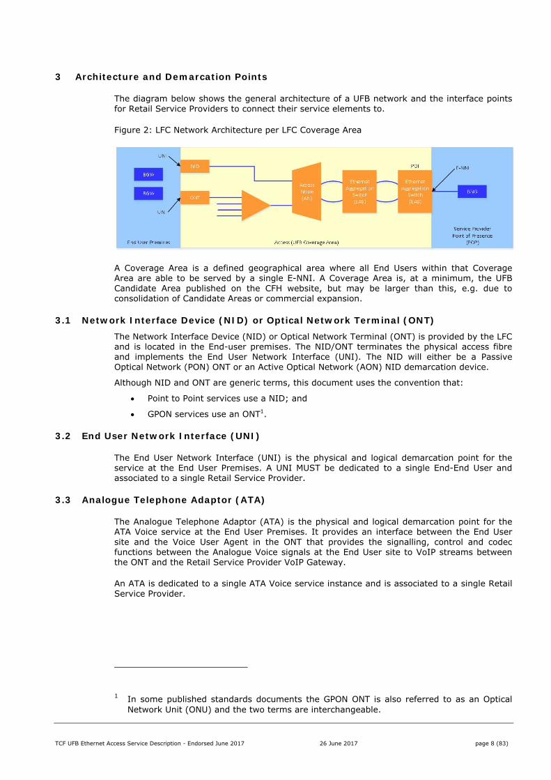
3 Architecture and Demarcation Points
The diagram below shows the general architecture of a UFB network and the interface points for Retail Service Providers to connect their service elements to.
Figure 2: LFC Network Architecture per LFC Coverage Area
A Coverage Area is a defined geographical area where all End Users within that Coverage Area are able to be served by a single E-NNI. A Coverage Area is, at a minimum, the UFB Candidate Area published on the CFH website, but may be larger than this, e.g. due to consolidation of Candidate Areas or commercial expansion.
3.1 Network Interface Device (NID) or Optical Network Terminal (ONT) The Network Interface Device (NID) or Optical Network Terminal (ONT) is provided by the LFC and is located in the End-user premises. The NID/ONT terminates the physical access fibre and implements the End User Network Interface (UNI). The NID will either be a Passive Optical Network (PON) ONT or an Active Optical Network (AON) NID demarcation device.
Although NID and ONT are generic terms, this document uses the convention that:
Point to Point services use a NID; and
GPON services use an ONT1.
3.2 End User Network Interface (UNI)
The End User Network Interface (UNI) is the physical and logical demarcation point for the service at the End User Premises. A UNI MUST be dedicated to a single End-End User and associated to a single Retail Service Provider.
3.3 Analogue Telephone Adaptor (ATA)
The Analogue Telephone Adaptor (ATA) is the physical and logical demarcation point for the ATA Voice service at the End User Premises. It provides an interface between the End User site and the Voice User Agent in the ONT that provides the signalling, control and codec functions between the Analogue Voice signals at the End User site to VoIP streams between the ONT and the Retail Service Provider VoIP Gateway.
An ATA is dedicated to a single ATA Voice service instance and is associated to a single Retail Service Provider.
1 In some published standards documents the GPON ONT is also referred to as an Optical
Network Unit (ONU) and the two terms are interchangeable.
TCF UFB Ethernet Access Service Description - Endorsed June 2017 26 June 2017 page 9 (83)
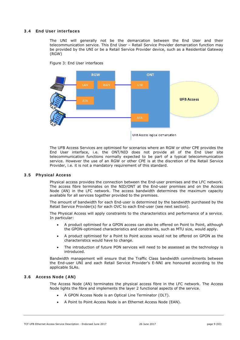
3.4 End User interfaces
The UNI will generally not be the demarcation between the End User and their telecommunication service. This End User – Retail Service Provider demarcation function may be provided by the UNI or be a Retail Service Provider device, such as a Residential Gateway (RGW)
Figure 3: End User interfaces
The UFB Access Services are optimised for scenarios where an RGW or other CPE provides the End User interface, i.e. the ONT/NID does not provide all of the End User site telecommunication functions normally expected to be part of a typical telecommunication service. However the use of an RGW or other CPE is at the discretion of the Retail Service Provider, i.e. it is not a mandatory requirement of this standard.
3.5 Physical Access Physical access provides the connection between the End-user premises and the LFC network. The access fibre terminates on the NID/ONT at the End-user premises and on the Access Node (AN) in the LFC network. The access bandwidth determines the maximum capacity available for all services together provided to the premises.
The amount of bandwidth for each End-user is determined by the bandwidth purchased by the Retail Service Provider(s) for each OVC to each End-user (see next section).
The Physical Access will apply constraints to the characteristics and performance of a service. In particular:
A product optimised for a GPON access can also be offered on Point to Point, although the GPON-optimised characteristics and constraints, such as MTU size, would apply.
A product optimised for a Point to Point access would not be offered on GPON as the characteristics would have to change.
The introduction of future PON services will need to be assessed as the technology is introduced.
Bandwidth management will ensure that the Traffic Class bandwidth commitments between the End-user UNI and each Retail Service Provider’s E-NNI are honoured according to the applicable SLAs.
3.6 Access Node (AN) The Access Node (AN) terminates the physical access fibre in the LFC network. The Access Node lights the fibre and implements the layer 2 functional aspects of the service.
A GPON Access Node is an Optical Line Terminator (OLT).
A Point to Point Access Node is an Ethernet Access Node (EAN).
TCF UFB Ethernet Access Service Description - Endorsed June 2017 26 June 2017 page 10 (83)
3.7 Ethernet Aggregation Switch (EAS) The Ethernet Aggregation Switch performs the TR-101/156 aggregation functions and will combine and manage traffic from a number of Access Nodes. There may be one or more layers of aggregation in an LFC network depending on the individual geographic and network topology requirements.
The EAS implements the External-Network Network Interface (E-NNI) functions.
3.8 External Network to Network Interface (E-NNI) External-Network Network Interface (E-NNI) is the physical and logical demarcation point for the service at the Point of Interconnect (POI) and serves as the boundary between the LFC Ethernet network and the Retail Service Provider network which operate as separate administrative domains. The E-NNI will be one or more physical Ethernet interfaces, carrying multiplexed traffic streams from End-users.
Logical Architecture
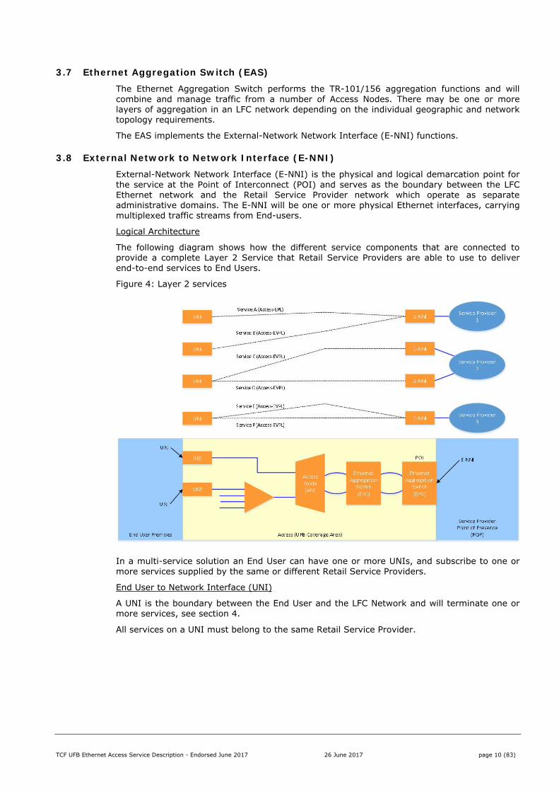
The following diagram shows how the different service components that are connected to provide a complete Layer 2 Service that Retail Service Providers are able to use to deliver end-to-end services to End Users.
Figure 4: Layer 2 services
In a multi-service solution an End User can have one or more UNIs, and subscribe to one or more services supplied by the same or different Retail Service Providers.
End User to Network Interface (UNI)
A UNI is the boundary between the End User and the LFC Network and will terminate one or more services, see section 4.
All services on a UNI must belong to the same Retail Service Provider.
TCF UFB Ethernet Access Service Description - Endorsed June 2017 26 June 2017 page 11 (83)
3.8.1 Handover Connection The Handover Connection provides the boundary between the Retail Service Provider Point of Presence and the LFC network. It terminates multiple services from multiple End Users and includes the following items:
E-NNI
Physical Ethernet ports on EAS
Fibre from the physical Ethernet ports to the LFC OFDF
Link aggregation (LAG) is based on the Link Aggregation Control Protocol (LACP) and is used to increase bandwidth and/or Ethernet link redundancy. LAG is used to aggregate together one or more physical links into a LAG group as follows:
Single sub-group:
o 1-2 Active links load sharing.
Dual sub-group:
o 1-2 Active sub-group;
o 0-2 ‘Slave’ or ‘standby’ sub-group;
Both sub-groups must be at the same POI.
Some LFCs may support more than 2 physical ports in a LAG sub-group.
Sub-groups do not need to have the same number of links. However if the inactive sub-group has less bandwidth than the active sub-group, then switching to the secondary sub-group will result in a reduction of bandwidth which may result in E-NNI overbooking and thus impact the service level commitments.
3.8.2 Operator Virtual Connection (OVC) The OVC is the association, and associated traffic policies, between a User Network Interface (UNI) located at the End User site and an External Network to Network Interface (E-NNI) located at the Point of Interconnect (POI).
The OVC service attributes and parameters (e.g. CoS, VLAN, bandwidth profile etc.) are described in part II of this document.
The OVC for point-to-point Access Ethernet Virtual Private Line (Access-EVPL) and Access Ethernet Private Line (Access-EPL) Services supports unicast delivery of Ethernet service frames.
The OVC for point to multipoint Ethernet Multicast Access (EMA) supports the multicast delivery of Ethernet multicast frames.
Services are demarcated as follows:
One OVC service per UNI
One OVC service per VLAN on an UNI
One service per vlan (Service VLAN or Service VLAN/Customer VLAN) on an E-NNI
A Multicast Connection can be bound to a Unicast Access-EVPL OVC at the UNI, see part II.
TCF UFB Ethernet Access Service Description - Endorsed June 2017 26 June 2017 page 12 (83)
3.9 OAM Monitoring and Service Integrity
Ethernet OAM features provide services at the following levels:
1. Fault investigation, i.e. interface for proactive fault detection and resolution. For example this could be embedded in a service to reduce costs from ‘faults not found’ or speed up resolution.
2. Reporting, i.e. provide ongoing monitoring and reporting both for premium SLAs and customer information.
3. Integration, i.e. allow Retail Service Providers to integrate their own OAM systems to allow them to use their own tools for reporting and monitoring.
The architectural deployment of OAM will fall into three categories:
Category Description OAM Level
1 Internal Used by LFC for internal use and not directly exposed to Retail Service Providers but may be activated and exposed via a portal or B2B. Product and operational context specific.
0-2
2 Exposed Is able to be interacted with by a Retail Service Provider’s OAM solution. This is likely to be product specific.
3-4
3 Transparent All 802.1ag and Y.1731 frames OAM messages are passed through the UFB Access Service transparently. Product independent, except where it interacts with category 2.
3+
TCF UFB Ethernet Access Service Description - Endorsed June 2017 26 June 2017 page 13 (83)
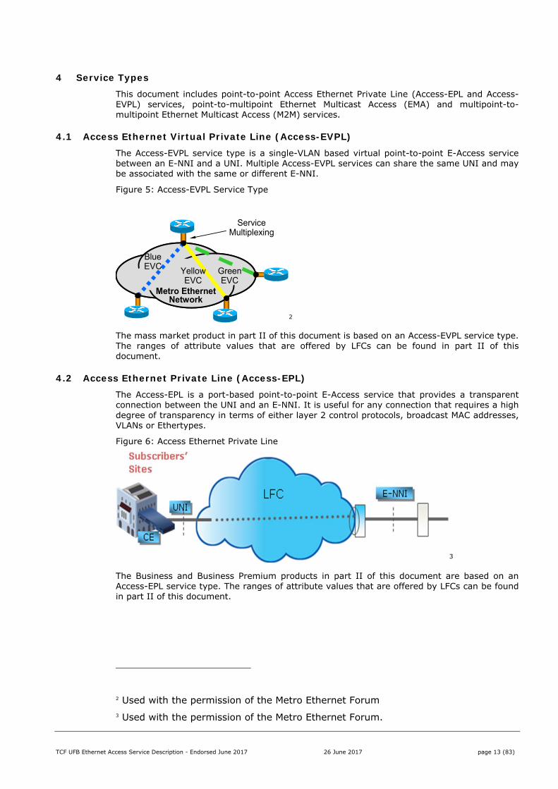
4 Service Types This document includes point-to-point Access Ethernet Private Line (Access-EPL and Access-EVPL) services, point-to-multipoint Ethernet Multicast Access (EMA) and multipoint-to-multipoint Ethernet Multicast Access (M2M) services.
4.1 Access Ethernet Virtual Private Line (Access-EVPL) The Access-EVPL service type is a single-VLAN based virtual point-to-point E-Access service between an E-NNI and a UNI. Multiple Access-EVPL services can share the same UNI and may be associated with the same or different E-NNI.
Figure 5: Access-EVPL Service Type
2
The mass market product in part II of this document is based on an Access-EVPL service type. The ranges of attribute values that are offered by LFCs can be found in part II of this document.
4.2 Access Ethernet Private Line (Access-EPL) The Access-EPL is a port-based point-to-point E-Access service that provides a transparent connection between the UNI and an E-NNI. It is useful for any connection that requires a high degree of transparency in terms of either layer 2 control protocols, broadcast MAC addresses, VLANs or Ethertypes.
Figure 6: Access Ethernet Private Line
3
The Business and Business Premium products in part II of this document are based on an Access-EPL service type. The ranges of attribute values that are offered by LFCs can be found in part II of this document.
2 Used with the permission of the Metro Ethernet Forum 3 Used with the permission of the Metro Ethernet Forum.
Metro Ethernet Network
Service Multiplexing
Blue EVC Yellow
EVCGreen EVC

TCF UFB Ethernet Access Service Description - Endorsed June 2017 26 June 2017 page 14 (83)
4.3 Ethernet Virtual Private Tree (EVP-Tree) The EVP-Tree service is a VLAN-based service of type E-Tree. The EVP-Tree service type is a rooted multi-point service, allowing the leaves (all End-users) to exchange traffic with the ‘root’ (the E-NNI) but not with each other.
The EMA service described in part II of this document uses a constrained version of an EVP-Tree service construct. Whereas a MEF EVP-Tree service supports Unicast, Multicast and Broadcast service frames, the EMA service only supports Multicast service frames between root and leaf and only IGMP (IPv4) or MLD (IPv6) control messages between leaf and root. Chapter 6 of the Broadband Forum’s TR-101 describes the requirements.
The choice of control messages (IGMP or MLD) is agreed between the LFC and Retail Service Provider per EVP-Tree solution.
Figure 7: Ethernet Virtual Private Tree (EVP-Tree)
4
The EMA product contains two service types:
An Ethernet Multicast Access service, which can be multiplexed with other services (Access-EVPL) at the UNI; and
An Ethernet Multicast Domain service that allows frames submitted at the E-NNI to be forwarded to the appropriate Access services.
4 Used with the permission of the Metro Ethernet Forum
TCF UFB Ethernet Access Service Description - Endorsed June 2017 26 June 2017 page 15 (83)
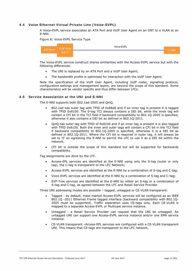
4.4 Voice Ethernet Virtual Private Line (Voice-EVPL) A Voice-EVPL service associates an ATA Port and VoIP User Agent on an ONT to a VLAN at an E-NNI.
Figure 8: Voice-EVPL Service Type
The Voice-EVPL service construct shares similarities with the Access-EVPL service but with the following differences:
The UNI is replaced by an ATA Port and a VoIP User Agent;
The bandwidth profile is optimised for interaction with the VoIP User Agent;
Note the specification of the VoIP User Agent, including VoIP codec, signalling protocol, configuration settings and management layers, are beyond the scope of this standard. Some characteristics will be vendor specific and thus differ between LFCs.
4.5 Service Association at the UNI and E-NNI The E-NNI supports both 802.1ad-2005 and QinQ.
802.1ad has outer tag with TPID of 0x88a8 and if an inner tag is present it is tagged with TPID 0x8100. The S-tag TCI always contains a DEI bit, while the inner tag will contain a CFI bit in the TCI field if backward compatibility to 802.1Q-2005 is specified, otherwise it also contains a DEI bit as defined in 802.1Q-2011.
QinQ has outer tag with TPID of 0x8100 and if an inner tag is present it is also tagged with TPID 0x8100. Both the inner and outer tags will contain a CFI bit in the TCI field if backward compatibility to 802.1Q-2005 is specified, otherwise it is a DEI bit as defined in 802.1Q-2011. Where the CFI bit is required in outer tag, it will always be set to ‘0’ on egressing the E-NNI to permit the LFC to use it as a DEI bit within the network.
CFI bit is outside the scope of this standard but will be supported for backwards compatibility.
Tag assignments are done by the LFC.
Access-EPL services are identified at the E-NNI using only the S-tag (outer or only tag), the C-tag is transparent to the LFC Network;
Access-EVPL services are identified at the E-NNI by a combination of S-tag and C-tag;
Voice EVPL services are identified at the E-NNI by a combination of S-tag and C-tag;
EVP-Tree services are identified at the E-NNI by either an S-tag or a combination of S-tag and C-tag, as agreed between the LFC and Retail Service Provider.
Three UNI addressing modes are possible – tagged, untagged or CE-VLAN transparent:
Tagged - by default, mass market Access-EVPL services will be configured as an IEEE 802.1Q -2011 Ethernet Frame tagged interface (backward compatibility with 802.1Q-2005 must be supported). Traffic separation uses CE-tags only. Each CE-VLAN is mapped to a separate Access-EVPL or Multicast service instance.
Untagged - a Retail Service Provider can request that the UNI be untagged. An untagged UNI can support one Access-EVPL service instance and/or one EMA service instance.
CE-VLAN transparent –Access-EPL services are configured with a CE-VLAN transparent UNI. This means that CE-tags are transparent to the LFC network.
TCF UFB Ethernet Access Service Description - Endorsed June 2017 26 June 2017 page 16 (83)
4.6 UFB Coverage Areas and E-NNI mapping Each End User is associated with a UFB Coverage area that comprises the geographical area served by one or two POIs. The following business rules apply:
An E-NNI must be located at a POI. If there is more than one POI for an area then an E-NNI can be located at either POI;
An OVC is associated with one UNI and one E-NNI in the same coverage area;
An OVC can be moved from one E-NNI to another E-NNI in the same Coverage Area. In practice this may involve tearing down the original OVC and building a new OVC associated to the second E-NNI but using the same common resources (UNI and UNI VLAN). The E-NNI VLAN ID (S-VID and/or C-VID) may change for the new OVC.
An E-NNI will have access to all End Users within a Coverage Area.
There are two mechanisms by which OVCs are associated to an E-NNI:
1. An aggregate level (per Access Node) where all service instances belonging to a particular Retail Service Provider on an Access Node are associated to the same E-NNI; or
2. Per OVC, where each service instance can be independently associated to any E-NNI in the same UFB Coverage Area that belongs to that Retail Service Provider.
The appropriate mechanisms are defined in each Ethernet Access Product in part II of this document.

TCF UFB Ethernet Access Service Description - Endorsed June 2017 26 June 2017 page 17 (83)
5 Bandwidth Profiles and Traffic Management
This section describes the bandwidth profiles and traffic management policies used to carry Ethernet frames across the LFC network.
5.1 Class of Service
Class of Service defines how traffic is treated when there is overbooking for resources. Examples of techniques used are:
Strict prioritisation, where any higher priority packets/frames are forwarded before any lower priority ones.
Weighted, where higher priority packets/frames are routed more frequently (at a specified rate, such as 3:1) than lower priority ones.
The following classes of service are defined per OVC:
Traffic Class CIR EIR
Low (L) ≥ 0 ≥ 0
High (H) ≥ 0 = 0
Where:
CIR is drop ineligible ('Green');
EIR is drop eligible ('Yellow');
Frames in excess of CIR+EIR within a traffic class are discarded (‘Red’).
Colour is a way of indicating the degree of compliance with a bandwidth profile. Packets that are in profile and must be carried are deemed ‘Green’, packets that are out of profile but within an acceptable range are deemed ‘Yellow’ and can be dropped if necessary, all other packets are out of profile, deemed ‘Red’. Red traffic is dropped immediately as per section 5.4.4.
Performance SLA metrics must be defined such that CIR and EIR Frame Delay and Frame Delay variation metrics are identical, with the only difference being the Frame Loss metrics. If CIR and EIR Frame Delay and Frame Delay variation metrics are different then frames will be reordered, resulting in poor End User experience.
5.2 Bandwidth Profile
There is one bandwidth profile per Class of Service per OVC as follows:
Attribute Description Values CIR Committed
Information Rate
Defines the average rate in bits/s of Service Frames up to which the network delivers Service Frames and meets the CIR performance objectives for the particular Traffic Class.
Mbps, as per Offer
CBS Committed Burst Size
Limits the maximum number of bytes available for a burst of Service Frames sent at the line rate to remain CIR-conformant.
kB
EIR Excess Information Rate
Defines the average rate in bits/s of Service Frames up to which the network delivers Service Frames and meets the EIR performance objectives for the particular Traffic Class.
Mbps, as per Offer
TCF UFB Ethernet Access Service Description - Endorsed June 2017 26 June 2017 page 18 (83)
Attribute Description Values EBS Excess Bust
size Limits the maximum number of bytes available for a burst of Service Frames sent at the line rate to remain EIR-conformant.
kB
CM Colour Mode CM is a Bandwidth Profile parameter. The Colour Mode parameter indicates whether the colour-aware or colour-blind property is employed by the Bandwidth Profile. It takes a value of “colour-blind” or “colour-aware” only
Colour blind or Colour Aware
CF Coupling Flag CF is a Bandwidth Profile parameter. The Coupling Flag allows the choice between two modes of operation of the rate enforcement algorithm. It takes a value of 0 or 1 only, where the value 1 allows unused CIR bandwidth to be added to the EIR bandwidth.
Off (0) Or on (1)
Note that the CIR and EIR performance objectives for each Traffic Class, including the Service Level Measurement and Reporting regime, are defined in the CFH UFB Layer 2 Performance Measurement and Reporting regime specification. It is important to note that LFC compliance with the CFH UFB Layer 2 Performance Measurement and Reporting regime is voluntary for UFB1, and mandatory for UFB2.
5.3 Packet Classification and Discard Eligibility using PCP values Individual frames are classified to belong to a defined Traffic Class using the Priority Code Point (PCP) field as follows:
Downstream
The PCP in the Service VLAN tag of Ethernet frames received at the E-NNI will be used to determine Traffic Class. The Customer VLAN tag PCP will be ignored.
Upstream
The PCP in the Customer VLAN tag will be used to determine Traffic Class
Untagged frames will be considered Low Traffic Class where multiple traffic classes exist for the OVC otherwise they will be considered as the default traffic class where a single traffic class exists.
The PCP mapping for each product is defined in part II of this document.
Note: that where there is a single traffic class per OVC such as a high priority only voice ATA service, or “Best Effort” only service, that it is not necessary to use the PCP field to mark the traffic class and specifying this in the service description is optional. Where the inappropriately PCP marked traffic is discarded such as for the voice ATA service, the service description shall identify this behaviour.
TCF UFB Ethernet Access Service Description - Endorsed June 2017 26 June 2017 page 19 (83)
5.4 Bandwidth, Colour marking, and Bandwidth sharing Bandwidth, Colour Marking, and Bandwidth sharing models and descriptions apply to a traffic class. .
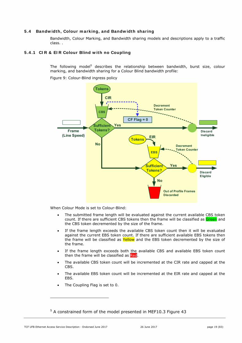
5.4.1 CIR & EIR Colour Blind with no Coupling
The following model5 describes the relationship between bandwidth, burst size, colour marking, and bandwidth sharing for a Colour Blind bandwidth profile:
Figure 9: Colour-Blind ingress policy
When Colour Mode is set to Colour-Blind:
The submitted frame length will be evaluated against the current available CBS token count. If there are sufficient CBS tokens then the frame will be classified as Green and the CBS token decremented by the size of the frame.
If the frame length exceeds the available CBS token count then it will be evaluated against the current EBS token count. If there are sufficient available EBS tokens then the frame will be classified as Yellow and the EBS token decremented by the size of the frame.
If the frame length exceeds both the available CBS and available EBS token count then the frame will be classified as Red.
The available CBS token count will be incremented at the CIR rate and capped at the CBS.
The available EBS token count will be incremented at the EIR rate and capped at the EBS.
The Coupling Flag is set to 0.
5 A constrained form of the model presented in MEF10.3 Figure 43
CBS
CIR
SufficientTokens?
No
Yes
DecrementToken Counter
Frame(Line Speed)
EBS
SufficientTokens?
No
Yes
DecrementToken Counter
DiscardIneligible
DiscardEligible
TokensEIR
Tokens
Out of Profile FramesDiscarded
CF Flag = 0
TCF UFB Ethernet Access Service Description - Endorsed June 2017 26 June 2017 page 20 (83)
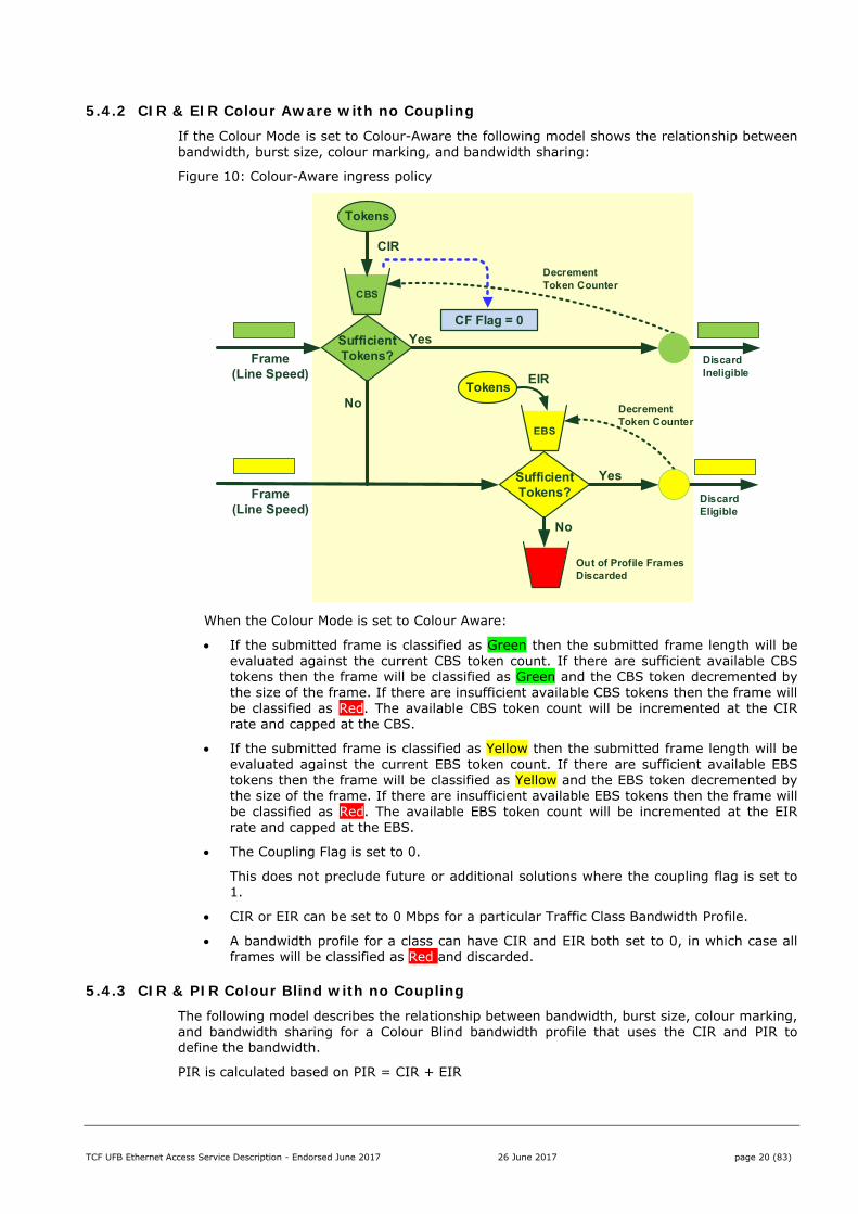
5.4.2 CIR & EIR Colour Aware with no Coupling If the Colour Mode is set to Colour-Aware the following model shows the relationship between bandwidth, burst size, colour marking, and bandwidth sharing:
Figure 10: Colour-Aware ingress policy
When the Colour Mode is set to Colour Aware:
If the submitted frame is classified as Green then the submitted frame length will be evaluated against the current CBS token count. If there are sufficient available CBS tokens then the frame will be classified as Green and the CBS token decremented by the size of the frame. If there are insufficient available CBS tokens then the frame will be classified as Red. The available CBS token count will be incremented at the CIR rate and capped at the CBS.
If the submitted frame is classified as Yellow then the submitted frame length will be evaluated against the current EBS token count. If there are sufficient available EBS tokens then the frame will be classified as Yellow and the EBS token decremented by the size of the frame. If there are insufficient available EBS tokens then the frame will be classified as Red. The available EBS token count will be incremented at the EIR rate and capped at the EBS.
The Coupling Flag is set to 0.
This does not preclude future or additional solutions where the coupling flag is set to 1.
CIR or EIR can be set to 0 Mbps for a particular Traffic Class Bandwidth Profile.
A bandwidth profile for a class can have CIR and EIR both set to 0, in which case all frames will be classified as Red and discarded.
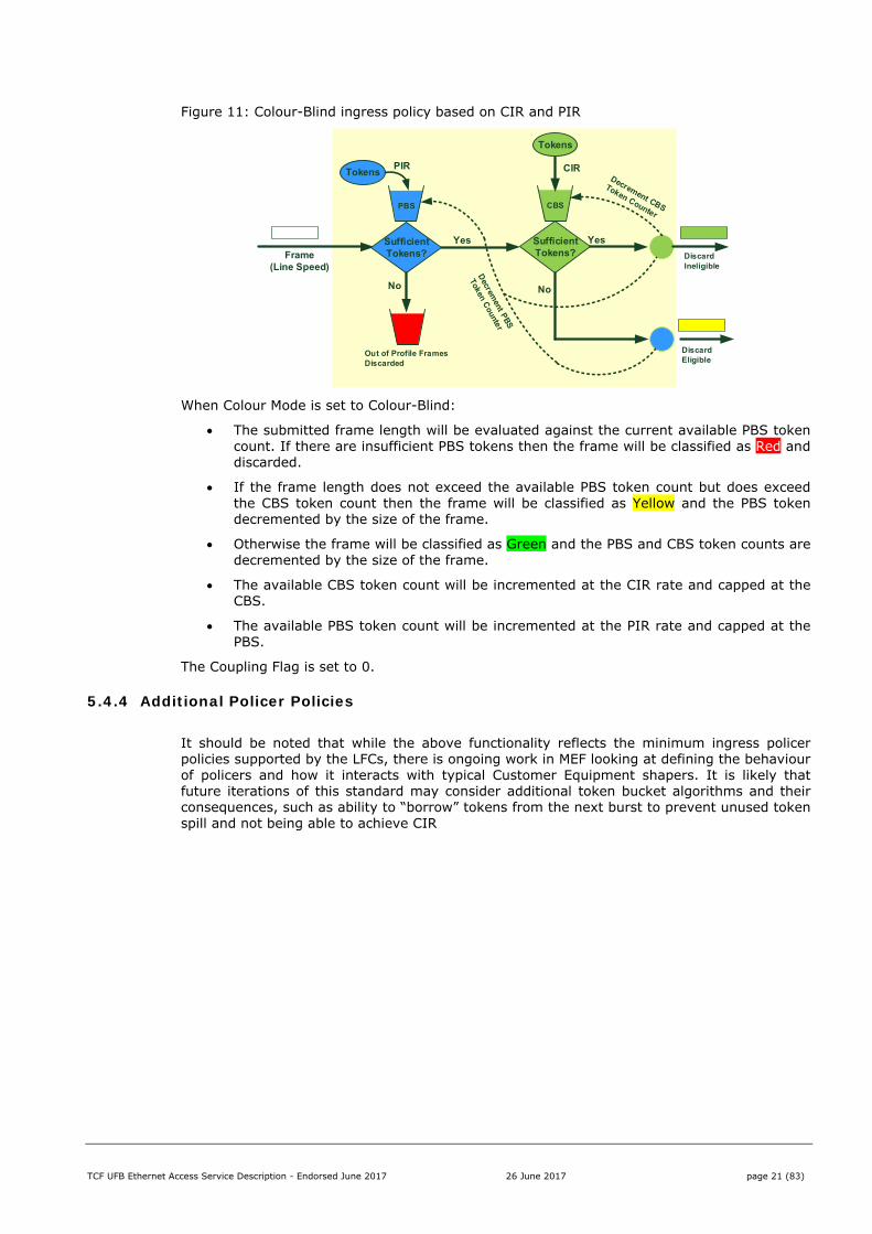
5.4.3 CIR & PIR Colour Blind with no Coupling The following model describes the relationship between bandwidth, burst size, colour marking, and bandwidth sharing for a Colour Blind bandwidth profile that uses the CIR and PIR to define the bandwidth.
PIR is calculated based on PIR = CIR + EIR
CBS
CIR
SufficientTokens?
No
Yes
DecrementToken Counter
Frame(Line Speed)
EBS
SufficientTokens?
No
Yes
DecrementToken Counter
DiscardIneligible
DiscardEligible
EIR
Out of Profile FramesDiscarded
CF Flag = 0
Frame(Line Speed)
Tokens
Tokens
TCF UFB Ethernet Access Service Description - Endorsed June 2017 26 June 2017 page 21 (83)
Figure 11: Colour-Blind ingress policy based on CIR and PIR
When Colour Mode is set to Colour-Blind:
The submitted frame length will be evaluated against the current available PBS token count. If there are insufficient PBS tokens then the frame will be classified as Red and discarded.
If the frame length does not exceed the available PBS token count but does exceed the CBS token count then the frame will be classified as Yellow and the PBS token decremented by the size of the frame.
Otherwise the frame will be classified as Green and the PBS and CBS token counts are decremented by the size of the frame.
The available CBS token count will be incremented at the CIR rate and capped at the CBS.
The available PBS token count will be incremented at the PIR rate and capped at the PBS.
The Coupling Flag is set to 0.
5.4.4 Additional Policer Policies
It should be noted that while the above functionality reflects the minimum ingress policer policies supported by the LFCs, there is ongoing work in MEF looking at defining the behaviour of policers and how it interacts with typical Customer Equipment shapers. It is likely that future iterations of this standard may consider additional token bucket algorithms and their consequences, such as ability to “borrow” tokens from the next burst to prevent unused token spill and not being able to achieve CIR
CBS
CIR
SufficientTokens?
No
Yes
Frame(Line Speed)
PBS
SufficientTokens?
No
Yes
DiscardIneligible
DiscardEligible
TokensPIR
Tokens
Out of Profile FramesDiscarded
TCF UFB Ethernet Access Service Description - Endorsed June 2017 26 June 2017 page 22 (83)
5.5 Delivery of Frames based on Colour classification The following table shows the base standard for how the LFC handles frames based on a Frame’s colour classification:
Colour Attribute Frame processing
Green CIR The LFC delivers Service Frames according the CIR performance objectives for the Frame’s Traffic Class.
Yellow EIR The LFC delivers Service Frames according the EIR performance objectives for the Frame’s Traffic Class.
Red - The LFC discards the frame
Note that discarding frames will impact the End User Customer Experience.
5.6 Overbooking at the E-NNI Retail Service Providers can choose to overbook the E-NNI. For frames to be considered to be within contract (i.e. subject to SLA) the upstream frames presented at each UNI must be within contract and the aggregated bandwidth presented to the E-NNI must be less than or equal to the handover bandwidth purchased by the RSP.
Downstream frames submitted at the E-NNI will always be within the handover connection interface speed but must be within contract for the respective services or the respective service ingress policer will discard out of contract frames.
5.7 End User Experience and Retail Service Provider Egress policies Retail Service Providers need to be aware that their End User experience is dependent on both the UFB Ethernet Access Services and their service and interface egress policies and therefore these policies should be configured commensurate with their service offerings. For example:
If the Retail Service Provider has purchased a 1 Gbps Handover Connection and the aggregate demand for services served by that handover exceeds 1 Gbps, then the excess frames need to be either queued or discarded, which will have an impact on the end user experience.
If the demand for a particular service exceeds the bandwidth profile for that service then the Retail Service Provider needs to decide whether to shape traffic to match the bandwidth profile or allow the Ethernet Access Service ingress policer to discard the excess frames. Both options will affect the End User experience.
5.8 Traffic Management and Security All traffic in the LFC network flows either from UNI to E-NNI or from E-NNI to UNI.
Direct UNI to UNI traffic or E-NNI to E-NNI traffic is not supported.
The LFC must, as far as possible, be entirely neutral with respect to the traffic it carries, i.e. the LFC, as a Layer 2 carrier, shall not inspect the contents of the End-users’ traffic unless it is necessary to do so to deliver Multicast (MLD or IGMP) snooping, Lawful Intercept, DHCP relay agent, PPPOE Intermediate agent or for diagnostic purposes to rectify a fault.
All invalid traffic must be silently dropped as soon as it is detected. Invalid traffic refers to frames with invalid FCS, destination or source address, short frames or long frames. It is acknowledged that there are multiple LFCs using multiple vendor equipment with different technical characteristics/limitations. Thus, despite best endeavours, the definition of invalid frames may be contextual and could vary between LFCs and services. In the event of the LFC dropping frames than Retail Service Provider considers valid then it is expected that:
1. The LFC and Retail Service Provider will work together to try and resolve the gap;
2. If necessary or appropriate then this gap will be raised at the Product Forum for resolution.
TCF UFB Ethernet Access Service Description - Endorsed June 2017 26 June 2017 page 23 (83)
5.9 Low Traffic Class Bandwidth Overhead There is a market expectation that the UFB offers can support their headline speed, particularly in the Residential, Education and SME market segments, i.e. a person on a 100/50 offer expects that they will often be able to achieve that speed. However UFB services are defined at Layer 2 whereas an End User observes speed at an application layer. This is particularly problematic in the residential space as consumer protection legislation applies.
This is less of an issue for High Traffic Class traffic or Business Services as the expectations for these markets are different.
To resolve this gap the Low Traffic Class includes a Bandwidth overhead to compensate for higher protocol encapsulation overheads. The minimum size of the overhead is calculated as follows:
10% overhead in Low Traffic Class Headline Rate downstream for bandwidths <200 Mbps, e.g. 33 Mbps for a 30 Mbps headline bandwidth;
8.5% overhead in Low Traffic Class Headline Rate downstream for bandwidths ≥ 200 Mbps e.g. 217 Mbps for a 200 Mbps headline bandwidth;
10% overhead in Low Traffic Class Headline Rate upstream, e.g. 44 Mbps for a 40 Mbps headline bandwidth;
Individual LFCs may choose to offer a larger overhead, as specified in the appropriate Service Specifications;
Maximum of UNI line rate. Note that any limits below UNI speed will be detailed in LFC service descriptions.
Where Headline Rate is the published (marketed) peak information rate for the service. For avoidance of doubt:
CIR+EIR = Headline Rate + overhead
The objective of this overhead is to make it possible for End Users to experience a typical speed meter experience (a server and algorithms for timed content transfers accessible from a user browser) at the headline rate. Note that this bandwidth overhead does not guarantee End Users will experience the headline speed as their experience is dependent on a number of external factors including, but not limited to, End User applications and local network, the Retail Service Provider network and location of the content they are accessing.
This overhead is only mandatory for GPON offers targeting Residential or Education markets.
It is optional for Point to Point Offers or GPON Offers targeting the Business markets.
TCF UFB Ethernet Access Service Description - Endorsed June 2017 26 June 2017 page 24 (83)
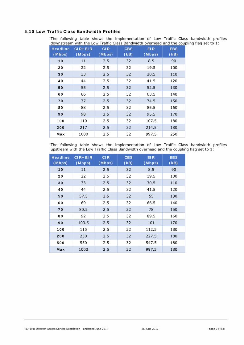
5.10 Low Traffic Class Bandwidth Profiles The following table shows the implementation of Low Traffic Class bandwidth profiles downstream with the Low Traffic Class Bandwidth overhead and the coupling flag set to 1: Headline (Mbps)
CIR+EIR (Mbps)
CIR (Mbps)
CBS (kB)
EIR (Mbps)
EBS (kB)
10 11 2.5 32 8.5 90
20 22 2.5 32 19.5 100
30 33 2.5 32 30.5 110
40 44 2.5 32 41.5 120
50 55 2.5 32 52.5 130
60 66 2.5 32 63.5 140
70 77 2.5 32 74.5 150
80 88 2.5 32 85.5 160
90 98 2.5 32 95.5 170
100 110 2.5 32 107.5 180
200 217 2.5 32 214.5 180
Max 1000 2.5 32 997.5 250
The following table shows the implementation of Low Traffic Class bandwidth profiles upstream with the Low Traffic Class Bandwidth overhead and the coupling flag set to 1:
Headline (Mbps)
CIR+EIR (Mbps)
CIR (Mbps)
CBS (kB)
EIR (Mbps)
EBS (kB)
10 11 2.5 32 8.5 90
20 22 2.5 32 19.5 100
30 33 2.5 32 30.5 110
40 44 2.5 32 41.5 120
50 57.5 2.5 32 55 130
60 69 2.5 32 66.5 140
70 80.5 2.5 32 78 150
80 92 2.5 32 89.5 160
90 103.5 2.5 32 101 170
100 115 2.5 32 112.5 180
200 230 2.5 32 227.5 180
500 550 2.5 32 547.5 180
Max 1000 2.5 32 997.5 180
TCF UFB Ethernet Access Service Description - Endorsed June 2017 26 June 2017 page 25 (83)
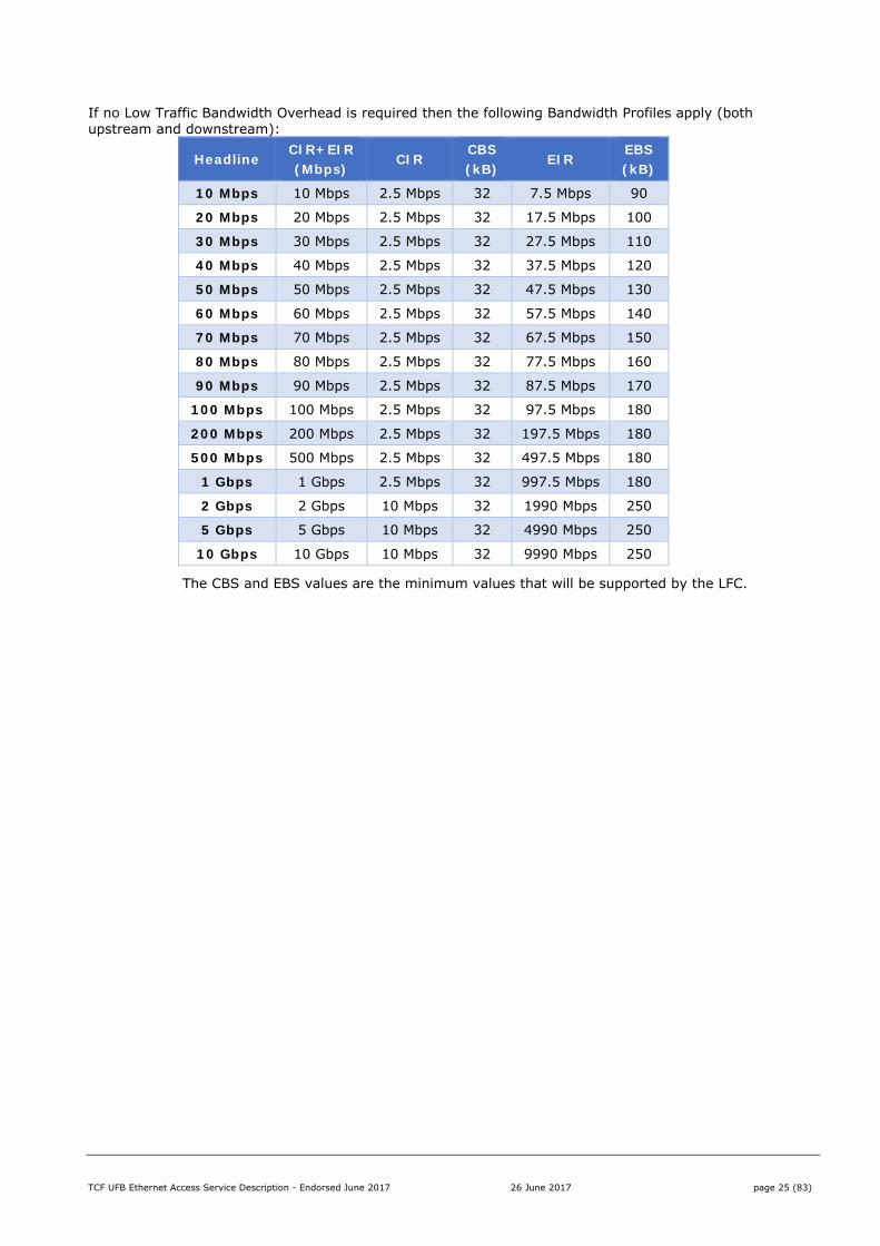
If no Low Traffic Bandwidth Overhead is required then the following Bandwidth Profiles apply (both upstream and downstream):
Headline CIR+EIR (Mbps)
CIR CBS (kB)
EIR EBS (kB)
10 Mbps 10 Mbps 2.5 Mbps 32 7.5 Mbps 90
20 Mbps 20 Mbps 2.5 Mbps 32 17.5 Mbps 100
30 Mbps 30 Mbps 2.5 Mbps 32 27.5 Mbps 110
40 Mbps 40 Mbps 2.5 Mbps 32 37.5 Mbps 120
50 Mbps 50 Mbps 2.5 Mbps 32 47.5 Mbps 130
60 Mbps 60 Mbps 2.5 Mbps 32 57.5 Mbps 140
70 Mbps 70 Mbps 2.5 Mbps 32 67.5 Mbps 150
80 Mbps 80 Mbps 2.5 Mbps 32 77.5 Mbps 160
90 Mbps 90 Mbps 2.5 Mbps 32 87.5 Mbps 170
100 Mbps 100 Mbps 2.5 Mbps 32 97.5 Mbps 180
200 Mbps 200 Mbps 2.5 Mbps 32 197.5 Mbps 180
500 Mbps 500 Mbps 2.5 Mbps 32 497.5 Mbps 180
1 Gbps 1 Gbps 2.5 Mbps 32 997.5 Mbps 180
2 Gbps 2 Gbps 10 Mbps 32 1990 Mbps 250
5 Gbps 5 Gbps 10 Mbps 32 4990 Mbps 250
10 Gbps 10 Gbps 10 Mbps 32 9990 Mbps 250
The CBS and EBS values are the minimum values that will be supported by the LFC.
TCF UFB Ethernet Access Service Description - Endorsed June 2017 26 June 2017 page 26 (83)
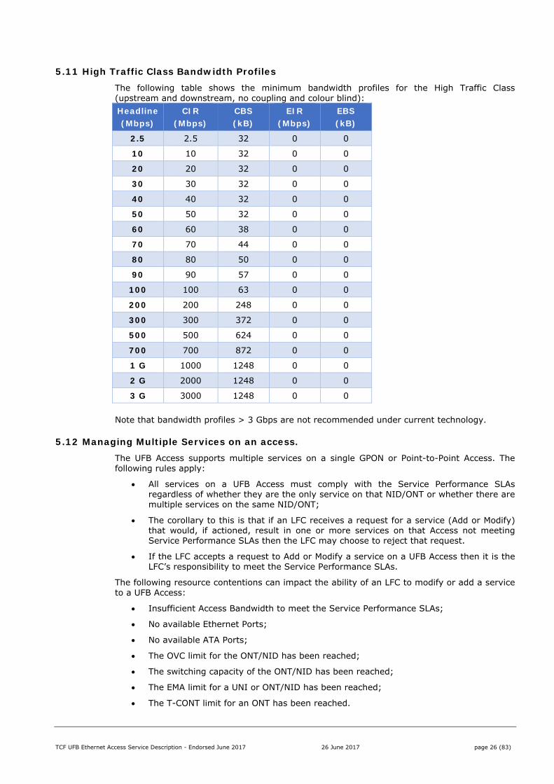
5.11 High Traffic Class Bandwidth Profiles The following table shows the minimum bandwidth profiles for the High Traffic Class (upstream and downstream, no coupling and colour blind): Headline (Mbps)
CIR (Mbps)
CBS (kB)
EIR (Mbps)
EBS (kB)
2.5 2.5 32 0 0
10 10 32 0 0
20 20 32 0 0
30 30 32 0 0
40 40 32 0 0
50 50 32 0 0
60 60 38 0 0
70 70 44 0 0
80 80 50 0 0
90 90 57 0 0
100 100 63 0 0
200 200 248 0 0
300 300 372 0 0
500 500 624 0 0
700 700 872 0 0
1 G 1000 1248 0 0
2 G 2000 1248 0 0
3 G 3000 1248 0 0
Note that bandwidth profiles > 3 Gbps are not recommended under current technology.
5.12 Managing Multiple Services on an access. The UFB Access supports multiple services on a single GPON or Point-to-Point Access. The following rules apply:
All services on a UFB Access must comply with the Service Performance SLAs regardless of whether they are the only service on that NID/ONT or whether there are multiple services on the same NID/ONT;
The corollary to this is that if an LFC receives a request for a service (Add or Modify) that would, if actioned, result in one or more services on that Access not meeting Service Performance SLAs then the LFC may choose to reject that request.
If the LFC accepts a request to Add or Modify a service on a UFB Access then it is the LFC’s responsibility to meet the Service Performance SLAs.
The following resource contentions can impact the ability of an LFC to modify or add a service to a UFB Access:
Insufficient Access Bandwidth to meet the Service Performance SLAs;
No available Ethernet Ports;
No available ATA Ports;
The OVC limit for the ONT/NID has been reached;
The switching capacity of the ONT/NID has been reached;
The EMA limit for a UNI or ONT/NID has been reached;
The T-CONT limit for an ONT has been reached.
TCF UFB Ethernet Access Service Description - Endorsed June 2017 26 June 2017 page 27 (83)
Each LFC must define and publish business rules as to how multiple services can be delivered on the same UFB Access.
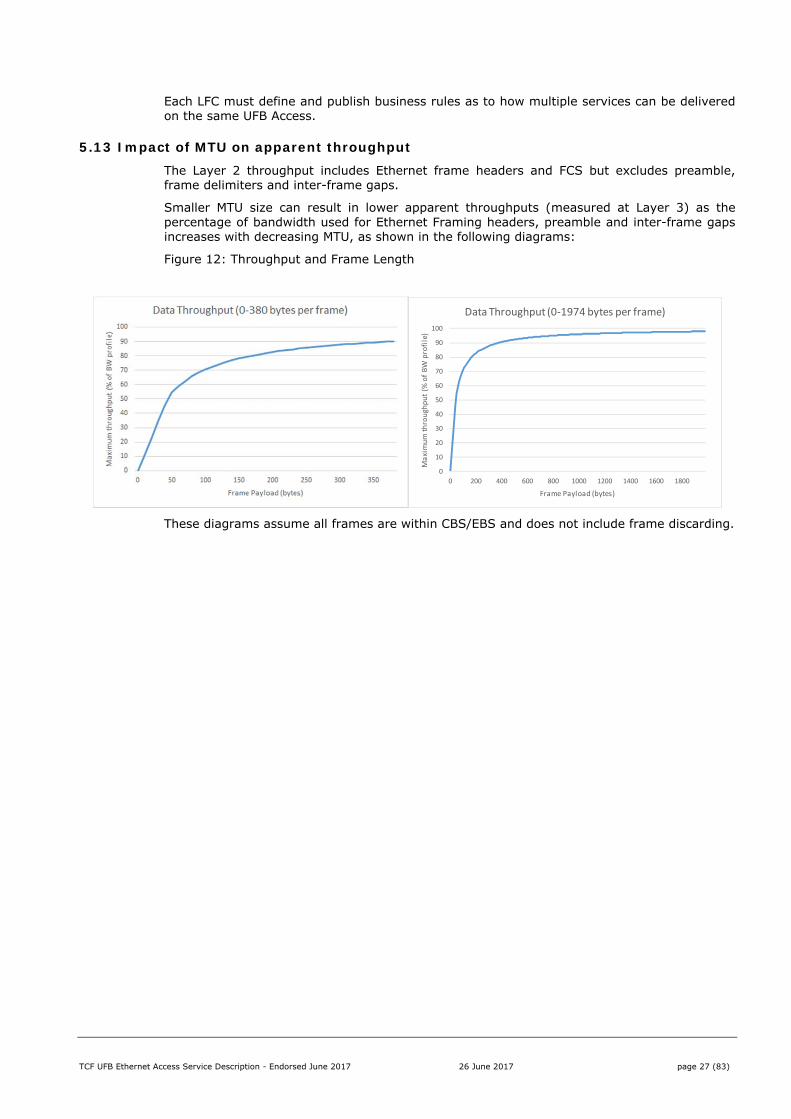
5.13 Impact of MTU on apparent throughput The Layer 2 throughput includes Ethernet frame headers and FCS but excludes preamble, frame delimiters and inter-frame gaps.
Smaller MTU size can result in lower apparent throughputs (measured at Layer 3) as the percentage of bandwidth used for Ethernet Framing headers, preamble and inter-frame gaps increases with decreasing MTU, as shown in the following diagrams:
Figure 12: Throughput and Frame Length
These diagrams assume all frames are within CBS/EBS and does not include frame discarding.
0
10
20
30
40
50
60
70
80
90
100
0 200 400 600 800 1000 1200 1400 1600 1800
Maximum throughput (%
of BW profile)
Frame Payload (bytes)
Data Throughput (0‐1974 bytes per frame)
TCF UFB Ethernet Access Service Description - Endorsed June 2017 26 June 2017 page 28 (83)
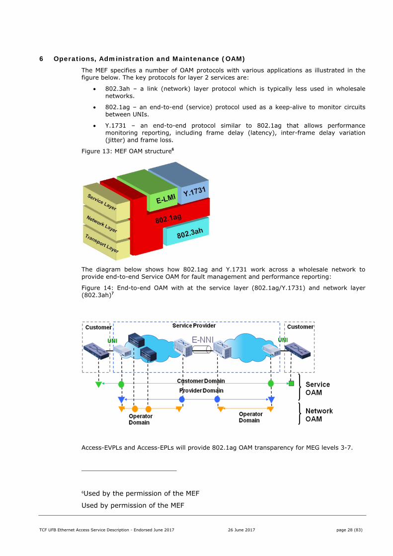
6 Operations, Administration and Maintenance (OAM) The MEF specifies a number of OAM protocols with various applications as illustrated in the figure below. The key protocols for layer 2 services are:
802.3ah – a link (network) layer protocol which is typically less used in wholesale networks.
802.1ag – an end-to-end (service) protocol used as a keep-alive to monitor circuits between UNIs.
Y.1731 – an end-to-end protocol similar to 802.1ag that allows performance monitoring reporting, including frame delay (latency), inter-frame delay variation (jitter) and frame loss.
Figure 13: MEF OAM structure6
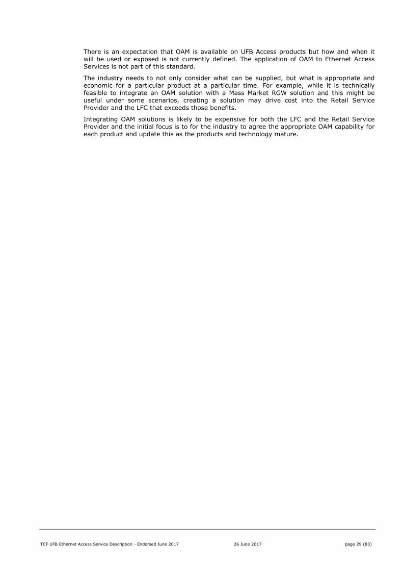
The diagram below shows how 802.1ag and Y.1731 work across a wholesale network to provide end-to-end Service OAM for fault management and performance reporting:
Figure 14: End-to-end OAM with at the service layer (802.1ag/Y.1731) and network layer (802.3ah)7
Access-EVPLs and Access-EPLs will provide 802.1ag OAM transparency for MEG levels 3-7.
6Used by the permission of the MEF
Used by permission of the MEF
TCF UFB Ethernet Access Service Description - Endorsed June 2017 26 June 2017 page 29 (83)
There is an expectation that OAM is available on UFB Access products but how and when it will be used or exposed is not currently defined. The application of OAM to Ethernet Access Services is not part of this standard.
The industry needs to not only consider what can be supplied, but what is appropriate and economic for a particular product at a particular time. For example, while it is technically feasible to integrate an OAM solution with a Mass Market RGW solution and this might be useful under some scenarios, creating a solution may drive cost into the Retail Service Provider and the LFC that exceeds those benefits.
Integrating OAM solutions is likely to be expensive for both the LFC and the Retail Service Provider and the initial focus is to for the industry to agree the appropriate OAM capability for each product and update this as the products and technology mature.
TCF UFB Ethernet Access Service Description - Endorsed June 2017 26 June 2017 page 30 (83)
Part II: Standard Product Definitions This section describes the current as-built UFB products available today, including the enhancements agreed by the Industry in December 2013)
It is noted that in some cases there are different interpretations and implementations of LFC solutions and these have been included where known.
TCF UFB Ethernet Access Service Description - Endorsed June 2017 26 June 2017 page 31 (83)
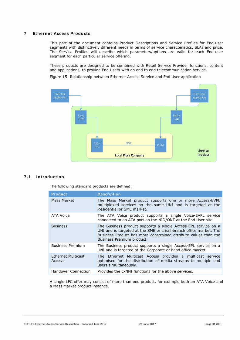
7 Ethernet Access Products
This part of the document contains Product Descriptions and Service Profiles for End-user segments with distinctively different needs in terms of service characteristics, SLAs and price. The Service Profiles will describe which parameters/options are valid for each End-user segment for each particular service offering.
These products are designed to be combined with Retail Service Provider functions, content and applications, to provide End Users with an end to end telecommunication service.
Figure 15: Relationship between Ethernet Access Service and End User application
7.1 Introduction
The following standard products are defined:
Product Description Mass Market The Mass Market product supports one or more Access-EVPL
multiplexed services on the same UNI and is targeted at the Residential or SME market.
ATA Voice The ATA Voice product supports a single Voice-EVPL service connected to an ATA port on the NID/ONT at the End User site.
Business The Business product supports a single Access-EPL service on a UNI and is targeted at the SME or small branch office market. The Business Product has more constrained attribute values than the Business Premium product.
Business Premium The Business product supports a single Access-EPL service on a UNI and is targeted at the Corporate or head office market.
Ethernet Multicast Access
The Ethernet Multicast Access provides a multicast service optimised for the distribution of media streams to multiple end users simultaneously.
Handover Connection Provides the E-NNI functions for the above services.
A single LFC offer may consist of more than one product, for example both an ATA Voice and a Mass Market product instance.

TCF UFB Ethernet Access Service Description - Endorsed June 2017 26 June 2017 page 32 (83)
7.2 Product Optimisation
The following table indicates the optimum target market for each product:
Product End User Retail Service Provider Mass Market Home, SME
< $ 100 CPE 1-8 active users
Large number of services on handover, e.g. 10 -20,000
ATA Voice Home, SME 1-2 Telephones
Business SME, Branch Office < $ 100 CPE < 40 active users
< 1000 per handover
Business Premium
Large Offices, Corporates > $ 500 CPE 20+ active users
< 250 per handover
EMA Home < $ 100 CPE 2 x set-top box
100+ TV Channels > 1 Gbps aggregate multicast traffic
Although these products are optimised for a particular market segment there are no technical restrictions that limit how they can be used. However this optimisation will be used to align the product features and avoid specifying uncommon or unsuitable features that might drive cost into consumption of that product.
Note that ‘Mass Market’ CPE is expected to get smarter and cheaper over time, e.g. future Residential Gateways may include features and performance that are, at the time of this standard, only available in expensive Business Premium CPE. However the introduction of features that rely on this new technology needs to consider the impact on End Users using older CPE and who may be slow or resistant to changing their CPE.
There may also be commercial constraints applied to some offers but that is outside the scope of this document.
TCF UFB Ethernet Access Service Description - Endorsed June 2017 26 June 2017 page 33 (83)
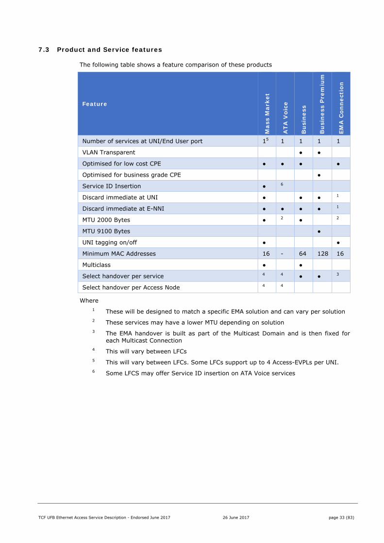
7.3 Product and Service features
The following table shows a feature comparison of these products
Feature
Mas
s M
arke
t
ATA
Voi
ce
Bu
sin
ess
Bu
sin
ess
Pre
miu
m
EMA
Con
nec
tion
Number of services at UNI/End User port 15 1 1 1 1
VLAN Transparent ● ●
Optimised for low cost CPE ● ● ● ●
Optimised for business grade CPE ●
Service ID Insertion ● 6
Discard immediate at UNI ● ● ● 1
Discard immediate at E-NNI ● ● ● ● 1
MTU 2000 Bytes ● 2 ● 2
MTU 9100 Bytes ●
UNI tagging on/off ● ●
Minimum MAC Addresses 16 - 64 128 16
Multiclass ● ●
Select handover per service 4 4 ● ● 3
Select handover per Access Node 4 4
Where 1 These will be designed to match a specific EMA solution and can vary per solution 2 These services may have a lower MTU depending on solution 3 The EMA handover is built as part of the Multicast Domain and is then fixed for
each Multicast Connection 4 This will vary between LFCs 5 This will vary between LFCs. Some LFCs support up to 4 Access-EVPLs per UNI. 6 Some LFCS may offer Service ID insertion on ATA Voice services
TCF UFB Ethernet Access Service Description - Endorsed June 2017 26 June 2017 page 34 (83)
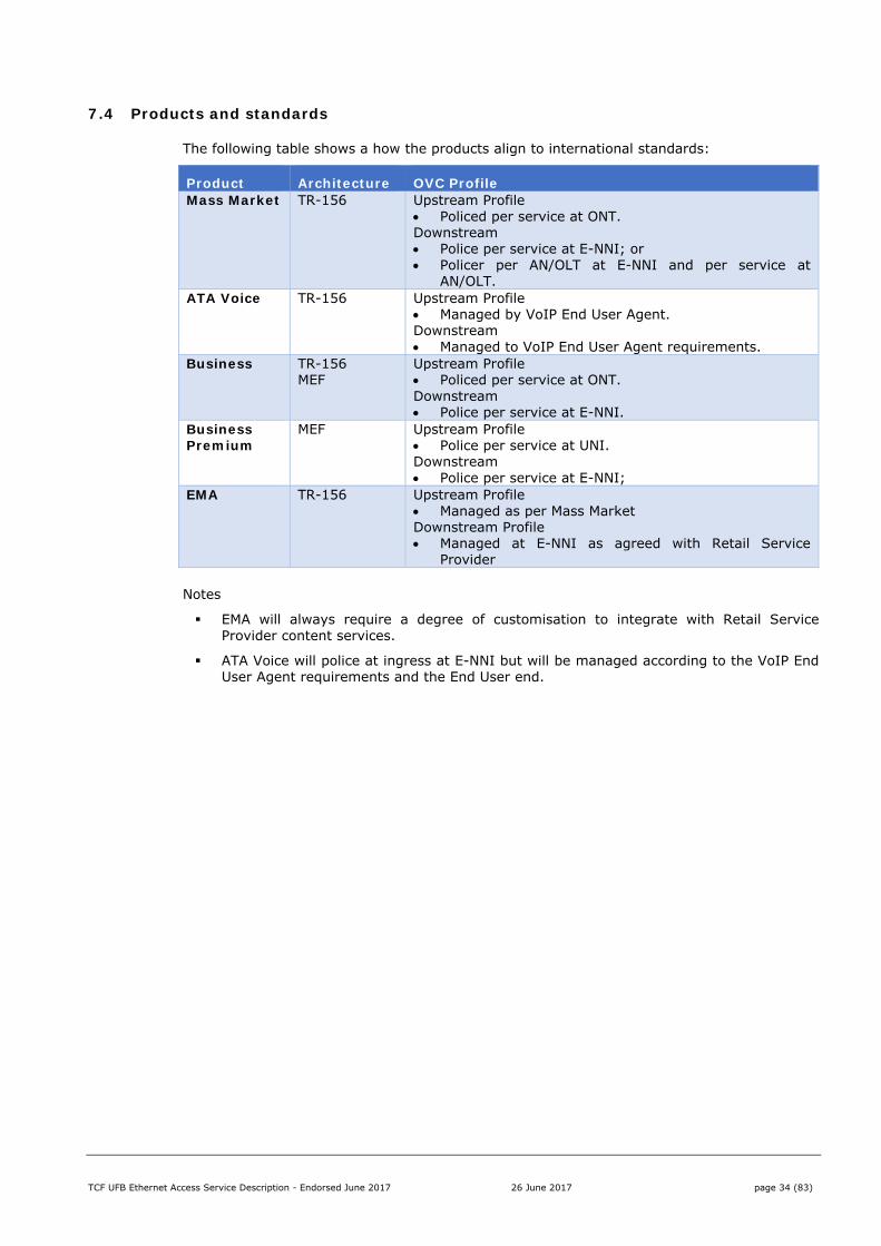
7.4 Products and standards
The following table shows a how the products align to international standards:
Product Architecture OVC Profile Mass Market TR-156 Upstream Profile
Policed per service at ONT. Downstream Police per service at E-NNI; or Policer per AN/OLT at E-NNI and per service at
AN/OLT. ATA Voice TR-156 Upstream Profile
Managed by VoIP End User Agent. Downstream Managed to VoIP End User Agent requirements.
Business TR-156 MEF
Upstream Profile Policed per service at ONT. Downstream Police per service at E-NNI.
Business Premium
MEF Upstream Profile Police per service at UNI. Downstream Police per service at E-NNI;
EMA TR-156 Upstream Profile Managed as per Mass Market Downstream Profile Managed at E-NNI as agreed with Retail Service
Provider
Notes
EMA will always require a degree of customisation to integrate with Retail Service Provider content services.
ATA Voice will police at ingress at E-NNI but will be managed according to the VoIP End User Agent requirements and the End User end.
TCF UFB Ethernet Access Service Description - Endorsed June 2017 26 June 2017 page 35 (83)
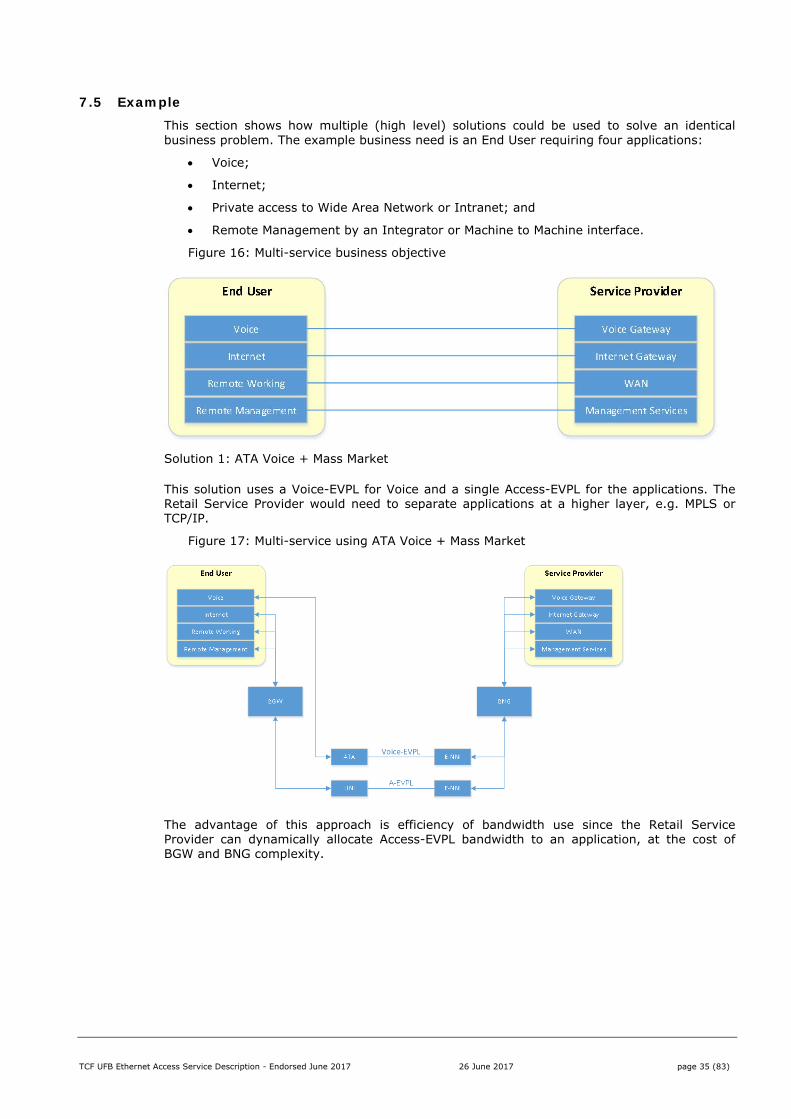
7.5 Example This section shows how multiple (high level) solutions could be used to solve an identical business problem. The example business need is an End User requiring four applications:
Voice;
Internet;
Private access to Wide Area Network or Intranet; and
Remote Management by an Integrator or Machine to Machine interface.
Figure 16: Multi-service business objective
Solution 1: ATA Voice + Mass Market
This solution uses a Voice-EVPL for Voice and a single Access-EVPL for the applications. The Retail Service Provider would need to separate applications at a higher layer, e.g. MPLS or TCP/IP.
Figure 17: Multi-service using ATA Voice + Mass Market
The advantage of this approach is efficiency of bandwidth use since the Retail Service Provider can dynamically allocate Access-EVPL bandwidth to an application, at the cost of BGW and BNG complexity.
TCF UFB Ethernet Access Service Description - Endorsed June 2017 26 June 2017 page 36 (83)
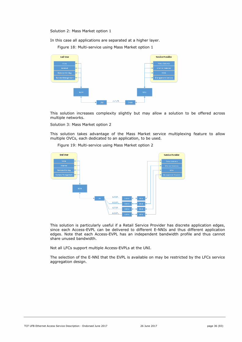
Solution 2: Mass Market option 1
In this case all applications are separated at a higher layer.
Figure 18: Multi-service using Mass Market option 1
This solution increases complexity slightly but may allow a solution to be offered across multiple networks.
Solution 3: Mass Market option 2
This solution takes advantage of the Mass Market service multiplexing feature to allow multiple OVCs, each dedicated to an application, to be used.
Figure 19: Multi-service using Mass Market option 2
This solution is particularly useful if a Retail Service Provider has discrete application edges, since each Access-EVPL can be delivered to different E-NNIs and thus different application edges. Note that each Access-EVPL has an independent bandwidth profile and thus cannot share unused bandwidth.
Not all LFCs support multiple Access-EVPLs at the UNI.
The selection of the E-NNI that the EVPL is available on may be restricted by the LFCs service aggregation design.
TCF UFB Ethernet Access Service Description - Endorsed June 2017 26 June 2017 page 37 (83)
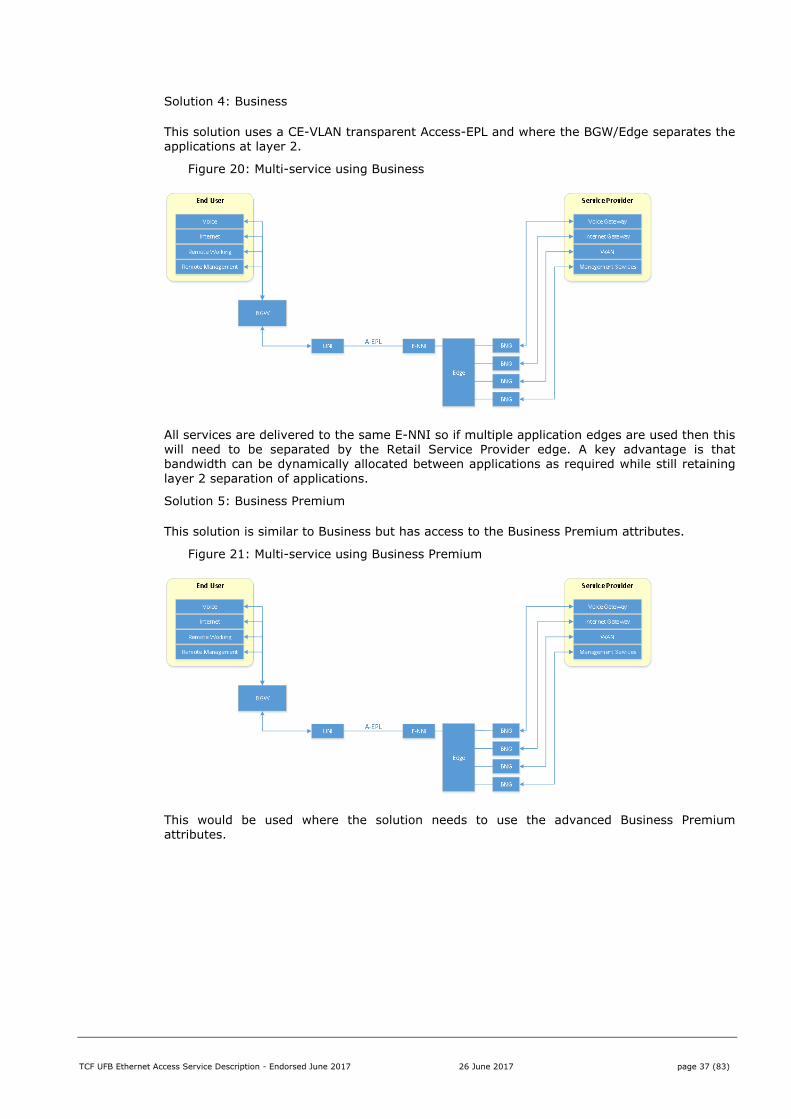
Solution 4: Business
This solution uses a CE-VLAN transparent Access-EPL and where the BGW/Edge separates the applications at layer 2.
Figure 20: Multi-service using Business
All services are delivered to the same E-NNI so if multiple application edges are used then this will need to be separated by the Retail Service Provider edge. A key advantage is that bandwidth can be dynamically allocated between applications as required while still retaining layer 2 separation of applications.
Solution 5: Business Premium
This solution is similar to Business but has access to the Business Premium attributes.
Figure 21: Multi-service using Business Premium
This would be used where the solution needs to use the advanced Business Premium attributes.
TCF UFB Ethernet Access Service Description - Endorsed June 2017 26 June 2017 page 38 (83)
8 Mass Market
The Mass Market product supports at least one Access-EVPL services multiplexed on the UNI and is targeted at the Residential or SME market.
The Mass Market service is optimised for Retail Service Providers offering layer 3 services, i.e. it is optimised for connectivity between an End User site and a Retail Service Provider layer 3 edge. It is not optimised for Retail Service Providers to interconnect two Mass Market End Users at layer 2 and using Mass Market to extend the reach of a layer 2 network may be problematic.
8.1 Key Features
Mass Market supports the following features:
Feature Values
UNI Tagging ON/OFF
E-NNI Tagging ON
Service ID Insertion DHCP/PPPoE/OFF
MTU 2000 bytes
Number of OVCs Up to 1 per UNI. Some LFCs support up to 4 per UNI.
OVC Bandwidth profile Low CIR/CBS/EIR/EBS
High CIR/CBS/EIR/EBS
UNI CE-VLAN ID One per OVC
Handover Mapping Pre-mapped
E-NNI VLAN ID One SVID/CVID per Access-EVPL OVC
MAC Addresses At least 16
Colour Colour Blind (at both UNI and E-NNI ingress and egress)
8.1.1 UNI Tagging
Attribute Values
On Default option
Upstream Frames presented at the UNI:
Frames that are 802.1Q-2011 tagged with a valid CE-VID will be accepted and PCP/CVID remarking performed if necessary as defined by the traffic classes for the service
Frames that are 802.1Q-2011 tagged with an invalid CE-VID are dropped
Frames that are Untagged or frames that are 802.1Q-2011 tagged with CE-VID=0 will be dropped.
Note that some LFCs will accept Untagged or frames that are 802.1Q-2011 tagged with CE-VID = 0 and apply a VLAN tag with PCP set to 0. This is considered an extension to this standard.
Downstream Frames presented at the UNI:
S-Tags are stripped at the ONT;
802.1Q-2011 C-tags at the ONT will be PCP/CVID remarked as necessary as defined by the traffic classes for the service.
TCF UFB Ethernet Access Service Description - Endorsed June 2017 26 June 2017 page 39 (83)
Attribute Values
Off Upstream Frames presented at the UNI:
Frames that are 802.1Q-2011 tagged with a CE-VID are dropped. Note that some LFCs will accept tagged frames with a specified CE-VID as per UNI tagging set to ON. This is considered an extension to this standard.
Frames that are Untagged will be accepted and tagged with PCP set to 0.
Downstream Frames presented at the UNI:
S-Tags are stripped at the ONT;
802.1 Q-2011 C-tags at the ONT are stripped and the untagged frames are presented to the UNI
A UNI with multiple OVCs terminating must have UNI tagging set to ON. However it is possible that one OVC can be set to untagged. This would be considered an extension to this standard.
8.1.2 E-NNI Tagging
E-NNI Tagging is always ON.
Upstream Frames presented at the E-NNI are 802.1ad double-tagged with a unique S-VID/C-VID per Access-EVPL.
Downstream frames submitted at the E-NNI must be 802.1ad double-tagged with the Access-EVPL S-VID/C-VID.
LFCs may optionally offer Q-in-Q or alternate Ethertypes.
8.1.3 Service ID Insertion Attribute Values
Off No Service ID is inserted into DHCP or PPPoE requests
DHCP The Service ID is inserted into:
DHCPv4 Option 82 as per RFC 4243, Remote ID field;
PPPoE The Service ID is inserted into the Remote Station ID field
The format of the Service ID will be LFC specific.
For more information on Service IDs, refer to TCF UFB BSS/OSS Business Interaction Framework.
If Service ID insertion is on then a Circuit ID will also be inserted. The format for the Circuit ID is LFC specific and this ID may change under operational user cases such as fault restoration or grooming.
Note: Circuit ID insertion may be enabled by some LFCs with the Service ID field being empty.
8.1.4 MTU
The Maximum Transmission Unit for the Access-EVPL is 2000 bytes. This includes frame header and checksum but excludes preamble frame delimiters and inter-frame gaps.
This includes the S-tag inserted by the network so the MTU at the UNI is 1996 bytes.
8.1.5 Number of OVCs
The Mass Market service supports at least one Access-EVPL per UNI.
TCF UFB Ethernet Access Service Description - Endorsed June 2017 26 June 2017 page 40 (83)
Some LFCs may support up to four Access-EVPLs per UNI.
8.1.6 OVC Bandwidth profile Attribute Values
Low Class of Service
Headline Rate = ‘Published’ Low Traffic Class Layer 2 rate before the overhead for higher protocols is included (see section 5.9
CIR = Committed Information Rate
CBS = Committed Burst Size
EIR = Excess Information rate (Headline Rate + L3+Overhead – Low Traffic Class CIR)
EBS = Excess Burst Size
High Class of Service
CIR = Committed Information Rate = High Traffic Class Headline Rate
CBS = Committed Burst Size
EIR = 0 Mbps
EBS = 0 kB
All Colour Blind (Single CE-VID PCP marking for each traffic class)
Coupling Flag Not Applicable
8.1.7 UNI CE-VLAN ID
The CE-VLAN ID per Access-EVPL per offer will be agreed between the Retail Service Provider and the LFC. It will remain static per offer to allow CPE (RGW/BGW) to be preconfigured
CE-VLAN IDs for public offers, i.e. services that are available to all Retail Service Providers, will be specified by the LFC in consultation with Retail Service Providers. The default VLAN for these offers is 10.
8.1.8 Handover Mapping
Each Access-EVPL on a UNI is mapped to a default handover which may be the same or different for other services on that UNI. This default handover is preset for each Retail Service Provider for each Coverage Area. If no default handover is available in a Coverage Area then no Access-EVPL services can be ordered for that Coverage Area.
Different Access-EVPLs on the same UNI may be mapped to the same or different handovers depending on the LFC’s traffic aggregation design.
Access-EVPLs can be moved from the default handover to optimise E-NNI efficiency and overbooking. Depending on the LFC this will be done at:
An aggregate level (per Access Node) where all service instances on that OLT are moved to the new handover; or
Per Access-EVPL instance, where this can be done as part of Connect or a subsequent modify service request.
The LFC must publish clear business rules on how they implement Handover Mapping and how Retail Service Providers can change Handover Mapping.
8.1.9 E-NNI VLAN ID
The E-NNI S-VID/C-VID VLAN ID is allocated by the LFC.
The Retail Service Provider can specify an S-VID whitelist for the E-NNI. If an S-VID whitelist is specified then the LFC will:
Assign the E-NNI S-VID out of this whitelist; and
Assign the E-NNI C-VID out of the valid C-VID range (2-4094);
TCF UFB Ethernet Access Service Description - Endorsed June 2017 26 June 2017 page 41 (83)
Note that some LFCs will allow Service Providers to define the S-VID/C-VID per Access-EVPL but the S-VID-C-VID must be unique per Handover Connection.
8.1.10 MAC Addresses
Mass Market supports at least 16 MAC addresses at the End User site, each capable of using all Traffic Classes.
Note that Mass Market users on the same Access Node are in the same Access Node layer 2 domain and this domain is MAC-address aware. A Retail Service Provider cannot forward Ethernet frames from one Access-EVPL instance to another Access-EVPL instance on the same OLT as the OLT will discard the downstream Ethernet frame due to a MAC address conflict.
8.1.11 Colour
The Mass Market service is Colour Blind (at both UNI and E-NNI ingress)
Two modes are allowed for UNI and E-NNI Egress Colour Marking:
Egress Colour Marking
Description
1 ON Frames will have their DEI bit set to 0 for CIR and 1 for EIR frames. This is for devices that comply with 802.1Q-2011.
2 OFF Frames will have their DEI bit set to 0. This is for backwards compatibility with 802.1Q-2005 where the same bit was used as CFI. This option ensures Low Traffic Class frames are correctly processed in older devices that comply with 802.1Q-2005 and expect Ethernet Frames to have a CFI value of 0.
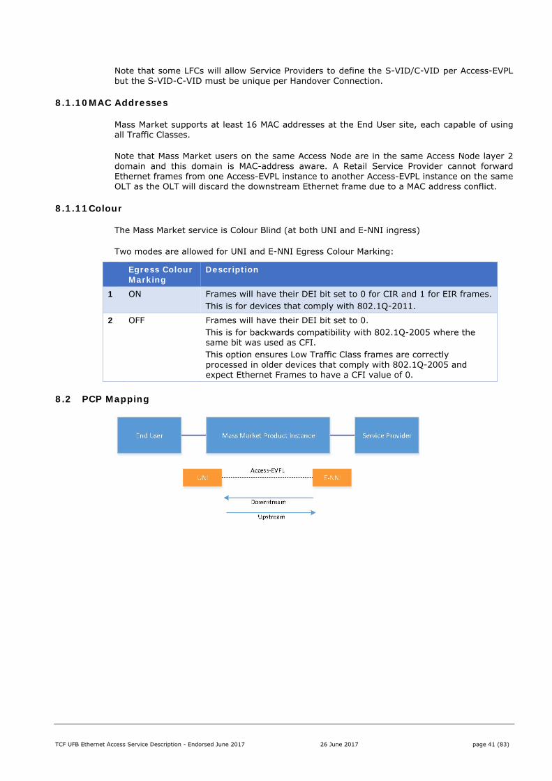
8.2 PCP Mapping
TCF UFB Ethernet Access Service Description - Endorsed June 2017 26 June 2017 page 42 (83)
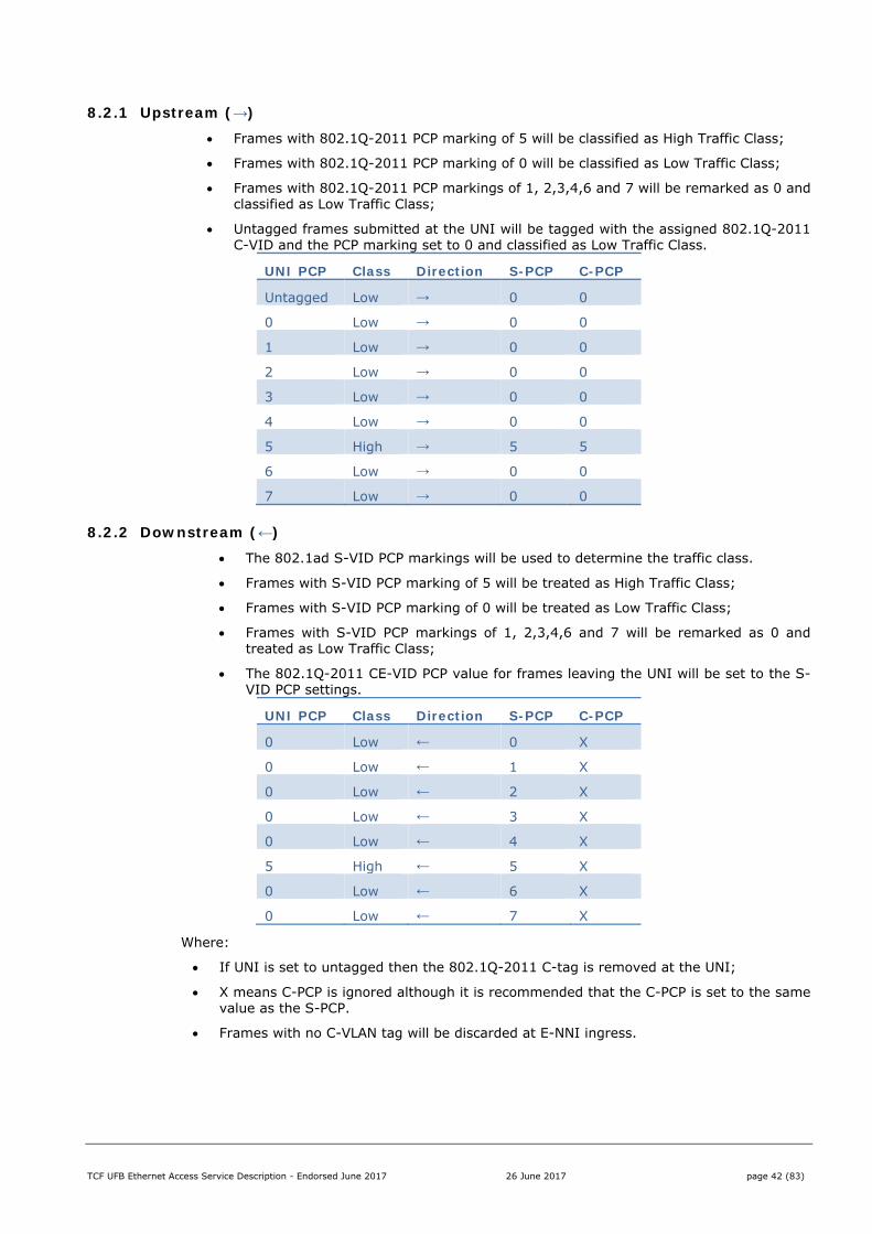
8.2.1 Upstream (→)
Frames with 802.1Q-2011 PCP marking of 5 will be classified as High Traffic Class;
Frames with 802.1Q-2011 PCP marking of 0 will be classified as Low Traffic Class;
Frames with 802.1Q-2011 PCP markings of 1, 2,3,4,6 and 7 will be remarked as 0 and classified as Low Traffic Class;
Untagged frames submitted at the UNI will be tagged with the assigned 802.1Q-2011 C-VID and the PCP marking set to 0 and classified as Low Traffic Class.
UNI PCP Class Direction S-PCP C-PCP
Untagged Low → 0 0
0 Low → 0 0
1 Low → 0 0
2 Low → 0 0
3 Low → 0 0
4 Low → 0 0
5 High → 5 5
6 Low → 0 0
7 Low → 0 0
8.2.2 Downstream (←)
The 802.1ad S-VID PCP markings will be used to determine the traffic class.
Frames with S-VID PCP marking of 5 will be treated as High Traffic Class;
Frames with S-VID PCP marking of 0 will be treated as Low Traffic Class;
Frames with S-VID PCP markings of 1, 2,3,4,6 and 7 will be remarked as 0 and treated as Low Traffic Class;
The 802.1Q-2011 CE-VID PCP value for frames leaving the UNI will be set to the S-VID PCP settings.
UNI PCP Class Direction S-PCP C-PCP
0 Low ← 0 X
0 Low ← 1 X
0 Low ← 2 X
0 Low ← 3 X
0 Low ← 4 X
5 High ← 5 X
0 Low ← 6 X
0 Low ← 7 X
Where:
If UNI is set to untagged then the 802.1Q-2011 C-tag is removed at the UNI;
X means C-PCP is ignored although it is recommended that the C-PCP is set to the same value as the S-PCP.
Frames with no C-VLAN tag will be discarded at E-NNI ingress.
TCF UFB Ethernet Access Service Description - Endorsed June 2017 26 June 2017 page 43 (83)
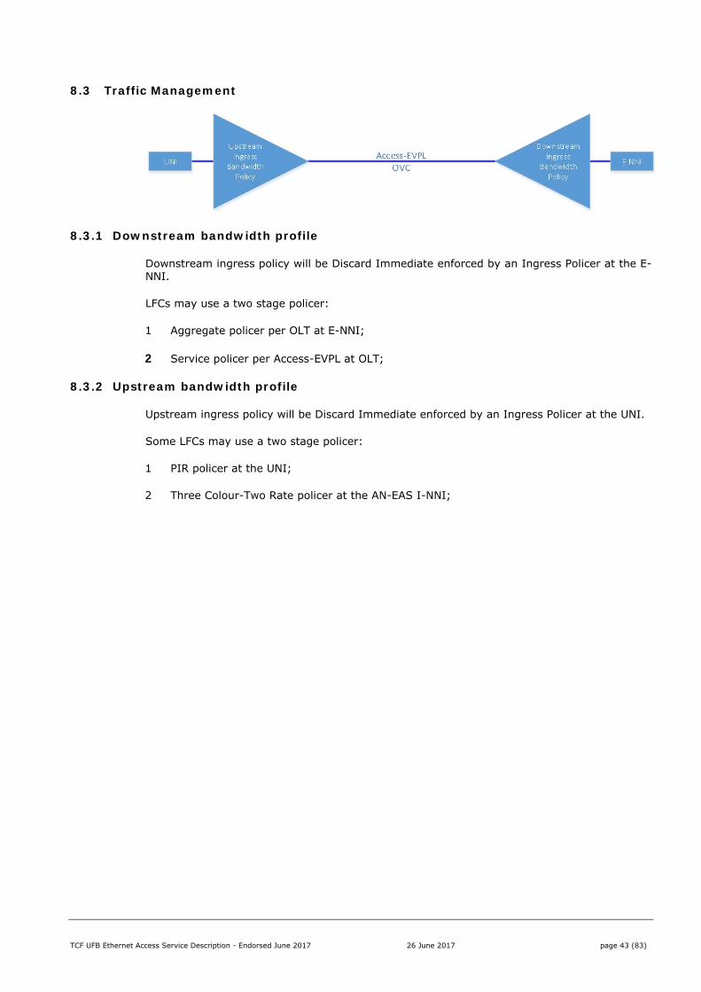
8.3 Traffic Management
8.3.1 Downstream bandwidth profile
Downstream ingress policy will be Discard Immediate enforced by an Ingress Policer at the E-NNI.
LFCs may use a two stage policer:
1 Aggregate policer per OLT at E-NNI;
2 Service policer per Access-EVPL at OLT;
8.3.2 Upstream bandwidth profile
Upstream ingress policy will be Discard Immediate enforced by an Ingress Policer at the UNI.
Some LFCs may use a two stage policer:
1 PIR policer at the UNI;
2 Three Colour-Two Rate policer at the AN-EAS I-NNI;
TCF UFB Ethernet Access Service Description - Endorsed June 2017 26 June 2017 page 44 (83)
8.4 Service Attributes for Mass Market
The tables below show the minimum service attributes and valid attribute value ranges for the Mass Market product.
8.4.1 UNI – Access-EVPL
Valid UNI attribute options for an Access-EVPL are shown in the table below:
Service attribute Valid attribute values
UNI Identifier <string> generated by OSS/BSS
Physical Medium 100Base-Tx/1000Base-T
Speed 100/1000 Mbit/s
Mode Full Duplex
MAC Layer IEEE 802.3-2012
UNI MTU Size 2000 bytes (1996 bytes at UNI)
Service Multiplexing Yes
Bundling No
All to One Bundling No
CE-VLAN ID for untagged and priority tagged Service Frames
Yes, by negotiation
Maximum number of OVCs 1. Some LFCs may allow up to 4.
Ingress Bandwidth Profile Per UNI Not Allowed
Egress Bandwidth Profile Per UNI Not Allowed
L2CP Processing See OVC detail.
Attribute Notes
Ingress bandwidth profiles only allowed on a per-OVC per-CoS basis.
Bundling is not allowed on the Mass Market service, but multiple single VLAN OVCs can be provided.
TCF UFB Ethernet Access Service Description - Endorsed June 2017 26 June 2017 page 45 (83)
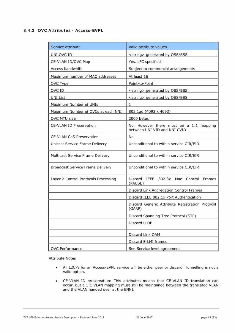
8.4.2 OVC Attributes - Access-EVPL
Service attribute Valid attribute values
UNI OVC ID <string> generated by OSS/BSS
CE-VLAN ID/OVC Map Yes. LFC specified
Access bandwidth Subject to commercial arrangements
Maximum number of MAC addresses At least 16
OVC Type Point-to-Point
OVC ID <string> generated by OSS/BSS
UNI List <string> generated by OSS/BSS
Maximum Number of UNIs 1
Maximum Number of OVCs at each NNI 802.1ad (4093 x 4093)
OVC MTU size 2000 bytes
CE-VLAN ID Preservation No. However there must be a 1:1 mapping between UNI VID and NNI CVID
CE-VLAN CoS Preservation No
Unicast Service Frame Delivery Unconditional to within service CIR/EIR
Multicast Service Frame Delivery Unconditional to within service CIR/EIR
Broadcast Service Frame Delivery Unconditional to within service CIR/EIR
Layer 2 Control Protocols Processing Discard IEEE 802.3x Mac Control Frames (PAUSE)
Discard Link Aggregation Control Frames
Discard IEEE 802.1x Port Authentication
Discard Generic Attribute Registration Protocol (GARP)
Discard Spanning Tree Protocol (STP)
Discard LLDP
Discard Link OAM
Discard E-LMI frames
OVC Performance See Service level agreement
Attribute Notes
All L2CPs for an Access-EVPL service will be either peer or discard. Tunnelling is not a valid option.
CE-VLAN ID preservation: This attributes means that CE-VLAN ID translation can occur, but a 1:1 VLAN mapping must still be maintained between the translated VLAN and the VLAN handed over at the ENNI.
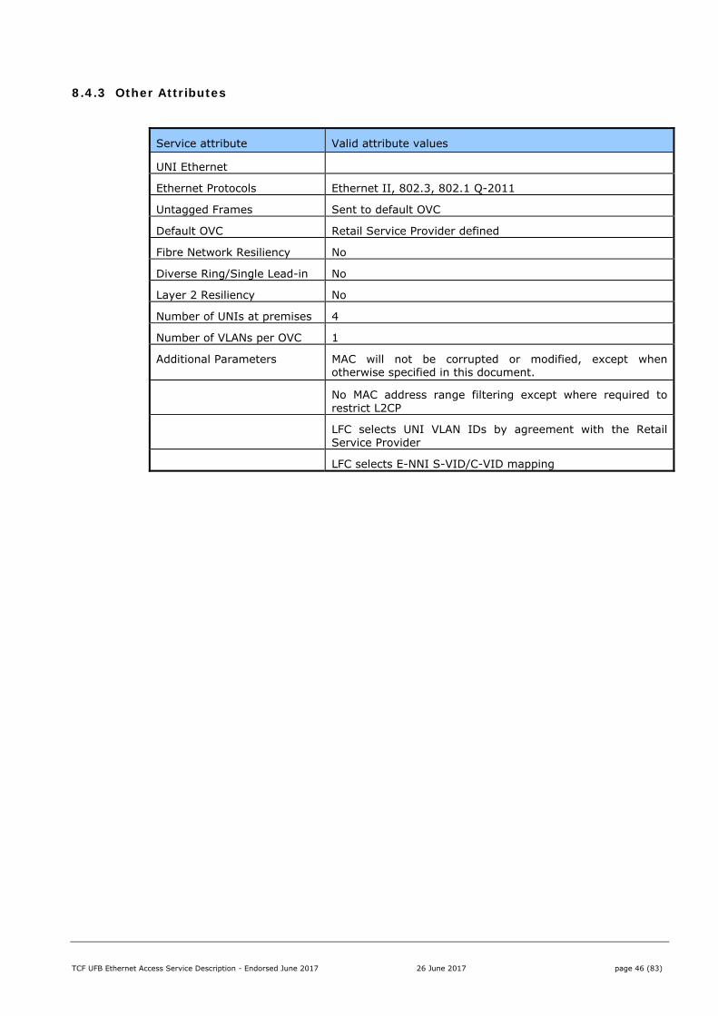
TCF UFB Ethernet Access Service Description - Endorsed June 2017 26 June 2017 page 46 (83)
8.4.3 Other Attributes
Service attribute Valid attribute values
UNI Ethernet
Ethernet Protocols Ethernet II, 802.3, 802.1 Q-2011
Untagged Frames Sent to default OVC
Default OVC Retail Service Provider defined
Fibre Network Resiliency No
Diverse Ring/Single Lead-in No
Layer 2 Resiliency No
Number of UNIs at premises 4
Number of VLANs per OVC 1
Additional Parameters MAC will not be corrupted or modified, except when otherwise specified in this document.
No MAC address range filtering except where required to restrict L2CP
LFC selects UNI VLAN IDs by agreement with the Retail Service Provider
LFC selects E-NNI S-VID/C-VID mapping
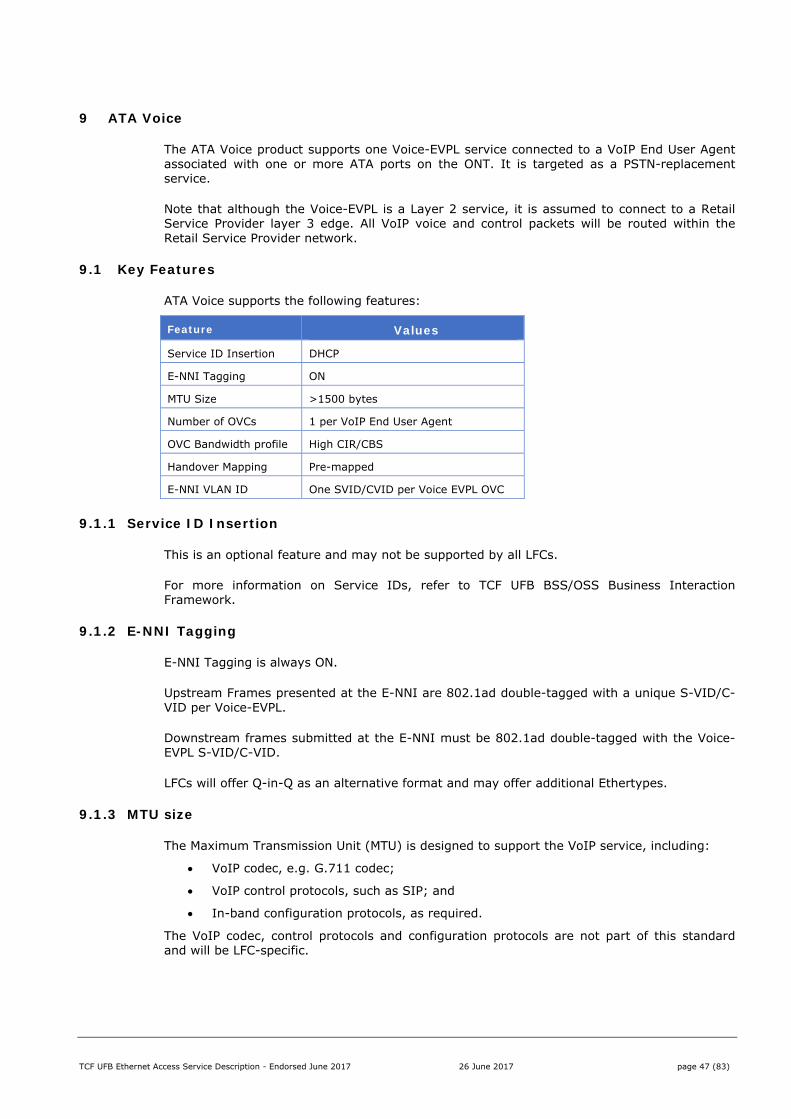
TCF UFB Ethernet Access Service Description - Endorsed June 2017 26 June 2017 page 47 (83)
9 ATA Voice
The ATA Voice product supports one Voice-EVPL service connected to a VoIP End User Agent associated with one or more ATA ports on the ONT. It is targeted as a PSTN-replacement service.
Note that although the Voice-EVPL is a Layer 2 service, it is assumed to connect to a Retail Service Provider layer 3 edge. All VoIP voice and control packets will be routed within the Retail Service Provider network.
9.1 Key Features
ATA Voice supports the following features:
Feature Values
Service ID Insertion DHCP
E-NNI Tagging ON
MTU Size >1500 bytes
Number of OVCs 1 per VoIP End User Agent
OVC Bandwidth profile High CIR/CBS
Handover Mapping Pre-mapped
E-NNI VLAN ID One SVID/CVID per Voice EVPL OVC
9.1.1 Service ID Insertion
This is an optional feature and may not be supported by all LFCs.
For more information on Service IDs, refer to TCF UFB BSS/OSS Business Interaction Framework.
9.1.2 E-NNI Tagging
E-NNI Tagging is always ON.
Upstream Frames presented at the E-NNI are 802.1ad double-tagged with a unique S-VID/C-VID per Voice-EVPL.
Downstream frames submitted at the E-NNI must be 802.1ad double-tagged with the Voice-EVPL S-VID/C-VID.
LFCs will offer Q-in-Q as an alternative format and may offer additional Ethertypes.
9.1.3 MTU size
The Maximum Transmission Unit (MTU) is designed to support the VoIP service, including:
VoIP codec, e.g. G.711 codec;
VoIP control protocols, such as SIP; and
In-band configuration protocols, as required.
The VoIP codec, control protocols and configuration protocols are not part of this standard and will be LFC-specific.
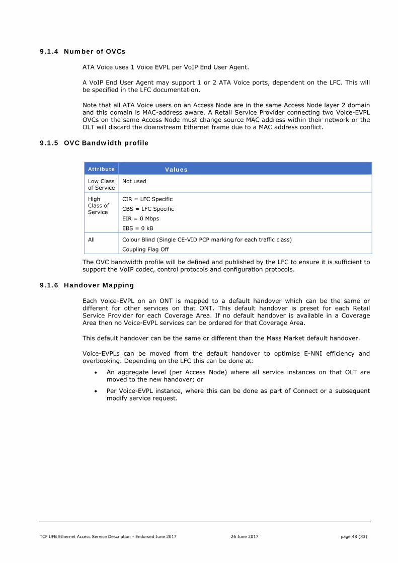
TCF UFB Ethernet Access Service Description - Endorsed June 2017 26 June 2017 page 48 (83)
9.1.4 Number of OVCs
ATA Voice uses 1 Voice EVPL per VoIP End User Agent.
A VoIP End User Agent may support 1 or 2 ATA Voice ports, dependent on the LFC. This will be specified in the LFC documentation.
Note that all ATA Voice users on an Access Node are in the same Access Node layer 2 domain and this domain is MAC-address aware. A Retail Service Provider connecting two Voice-EVPL OVCs on the same Access Node must change source MAC address within their network or the OLT will discard the downstream Ethernet frame due to a MAC address conflict.
9.1.5 OVC Bandwidth profile
Attribute Values
Low Class of Service
Not used
High Class of Service
CIR = LFC Specific
CBS = LFC Specific
EIR = 0 Mbps
EBS = 0 kB
All Colour Blind (Single CE-VID PCP marking for each traffic class)
Coupling Flag Off
The OVC bandwidth profile will be defined and published by the LFC to ensure it is sufficient to support the VoIP codec, control protocols and configuration protocols.
9.1.6 Handover Mapping
Each Voice-EVPL on an ONT is mapped to a default handover which can be the same or different for other services on that ONT. This default handover is preset for each Retail Service Provider for each Coverage Area. If no default handover is available in a Coverage Area then no Voice-EVPL services can be ordered for that Coverage Area.
This default handover can be the same or different than the Mass Market default handover.
Voice-EVPLs can be moved from the default handover to optimise E-NNI efficiency and overbooking. Depending on the LFC this can be done at:
An aggregate level (per Access Node) where all service instances on that OLT are moved to the new handover; or
Per Voice-EVPL instance, where this can be done as part of Connect or a subsequent modify service request.
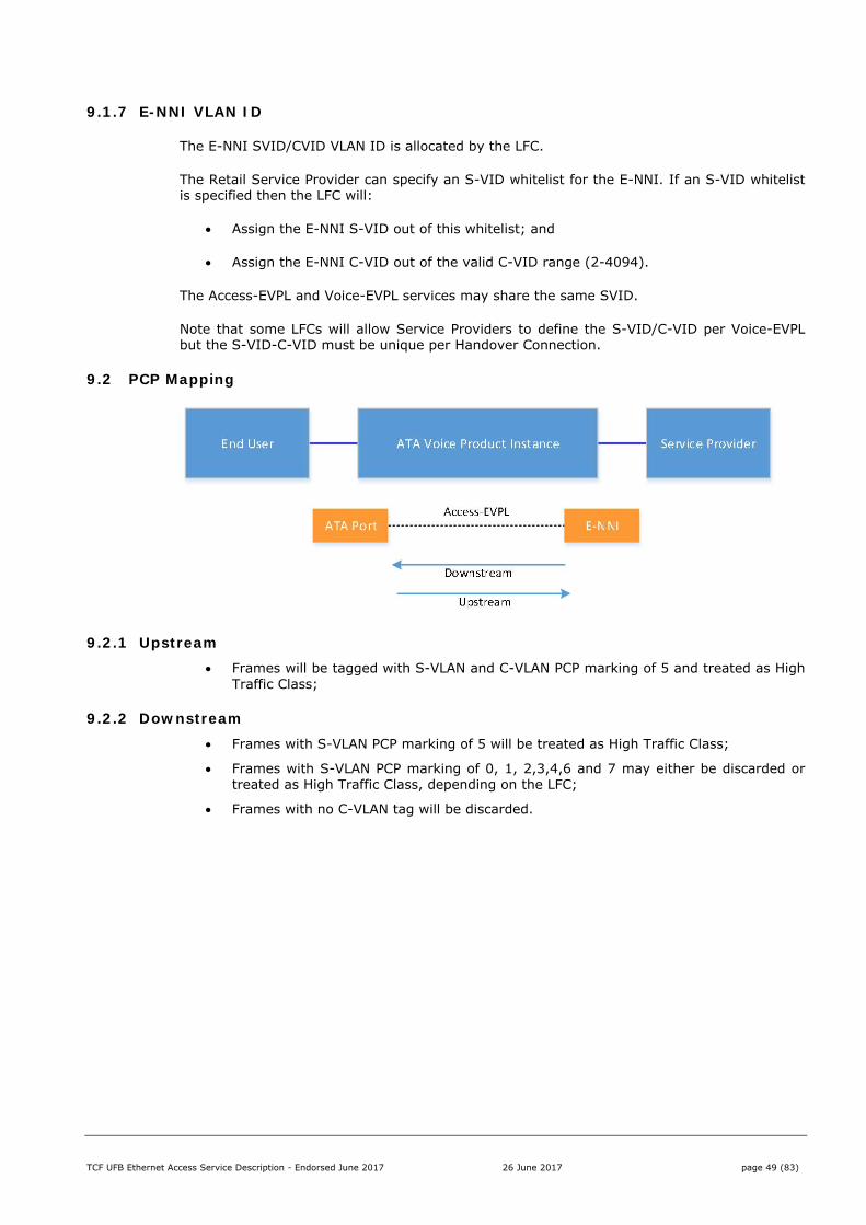
TCF UFB Ethernet Access Service Description - Endorsed June 2017 26 June 2017 page 49 (83)
9.1.7 E-NNI VLAN ID
The E-NNI SVID/CVID VLAN ID is allocated by the LFC.
The Retail Service Provider can specify an S-VID whitelist for the E-NNI. If an S-VID whitelist is specified then the LFC will:
Assign the E-NNI S-VID out of this whitelist; and
Assign the E-NNI C-VID out of the valid C-VID range (2-4094).
The Access-EVPL and Voice-EVPL services may share the same SVID.
Note that some LFCs will allow Service Providers to define the S-VID/C-VID per Voice-EVPL but the S-VID-C-VID must be unique per Handover Connection.
9.2 PCP Mapping
9.2.1 Upstream Frames will be tagged with S-VLAN and C-VLAN PCP marking of 5 and treated as High
Traffic Class;
9.2.2 Downstream Frames with S-VLAN PCP marking of 5 will be treated as High Traffic Class;
Frames with S-VLAN PCP marking of 0, 1, 2,3,4,6 and 7 may either be discarded or treated as High Traffic Class, depending on the LFC;
Frames with no C-VLAN tag will be discarded.
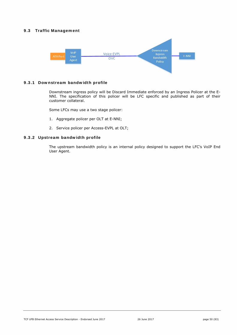
TCF UFB Ethernet Access Service Description - Endorsed June 2017 26 June 2017 page 50 (83)
9.3 Traffic Management
9.3.1 Downstream bandwidth profile
Downstream ingress policy will be Discard Immediate enforced by an Ingress Policer at the E-NNI. The specification of this policer will be LFC specific and published as part of their customer collateral.
Some LFCs may use a two stage policer:
1. Aggregate policer per OLT at E-NNI;
2. Service policer per Access-EVPL at OLT;
9.3.2 Upstream bandwidth profile
The upstream bandwidth policy is an internal policy designed to support the LFC’s VoIP End User Agent.
TCF UFB Ethernet Access Service Description - Endorsed June 2017 26 June 2017 page 51 (83)
9.4 Service Attributes for Voice-EVPL
The tables below show the minimum service attributes and valid attribute value ranges for the ATA Voice product.
9.4.1 ATA Port – Voice EVPL
The End User Interface will be an Analogue Telephone Adapter that supports a standard PSTN-grade analogue phone.
Each LFC shall publish their full interface standard for this port
9.4.2 OVC Attributes - Voice EVPL
Service attribute Valid attribute values
UNI OVC ID <string> generated by OSS/BSS
CE-VLAN ID/OVC Map Not applicable
Access bandwidth Subject to VoIP End User Agent requirements
Maximum number of MAC addresses N/A
OVC Type Point-to-Point
OVC ID <string> generated by OSS/BSS
UNI List <string> generated by OSS/BSS (ATA Port)
Maximum Number of UNIs 1 (User Agent)
Maximum Number of OVCs at each NNI 802.1ad (4093 x 4093)
OVC MTU size 2000 bytes*
MTU for VoIP User Agent will be LFC specific
CE-VLAN ID Preservation Not applicable
CE-VLAN CoS Preservation Not applicable
Unicast Service Frame Delivery Unconditional * [to High Traffic Class SLA].
Multicast Service Frame Delivery N/A
Broadcast Service Frame Delivery N/A
Layer 2 Control Protocols Processing N/A
OVC Performance See Service level agreement
TCF UFB Ethernet Access Service Description - Endorsed June 2017 26 June 2017 page 52 (83)
10 Business
The Business product supports a single Access-EPL services per UNI and is targeted at the SME or branch office market.
The Business product is optimised to support Retail Service Providers offering either Layer 2 or Layer 3 solutions.
10.1 Key Features
Business supports the following features:
Feature Values Number of OVCs 1 per UNI
E-NNI Tagging ON
MTU 2000 Bytes
Multiclass ON/OFF
MTU 2000 Bytes
OVC Bandwidth profile Low CIR/CBS/EIR/EBS High CIR/CBS/EIR/EBS
UNI VLAN ID VLAN transparent
Handover Mapping Mapped per Product Instance
E-NNI VLAN ID One SVID per Access-EPL OVC
MAC Addresses At least 64
Colour Colour Blind (at both UNI and E-NNI ingress and egress)
10.1.1 Number of OVCs
The Business Access-EPL service supports up to 1 Access-EPL per UNI.
10.1.2 E-NNI Tagging
E-NNI Tagging is always ON.
Upstream Frames presented at the E-NNI are 802.1ad single or double-tagged with a unique S-VID per Access-EVPL.
Downstream frames submitted at the E-NNI must be 802.1ad single or double-tagged with the Access-EPL S-VID.
LFCs will offer Q-in-Q as an alternative format and may offer additional Ethertypes.
10.1.3 MTU
The Maximum Transmission Unit for the Business Access-EPL is 2000 bytes. This includes frame header and checksum but excludes preamble frame delimiters and inter-frame gaps.
This includes the S-tag inserted by the network so the MTU at the UNI is 1996 bytes.
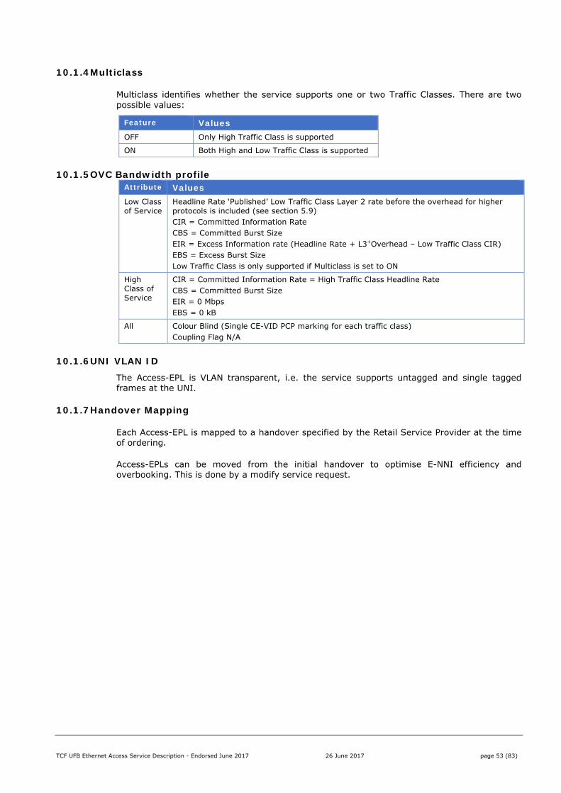
TCF UFB Ethernet Access Service Description - Endorsed June 2017 26 June 2017 page 53 (83)
10.1.4 Multiclass
Multiclass identifies whether the service supports one or two Traffic Classes. There are two possible values:
Feature Values OFF Only High Traffic Class is supported
ON Both High and Low Traffic Class is supported
10.1.5 OVC Bandwidth profile Attribute Values Low Class of Service
Headline Rate ‘Published’ Low Traffic Class Layer 2 rate before the overhead for higher protocols is included (see section 5.9) CIR = Committed Information Rate CBS = Committed Burst Size EIR = Excess Information rate (Headline Rate + L3+Overhead – Low Traffic Class CIR) EBS = Excess Burst Size Low Traffic Class is only supported if Multiclass is set to ON
High Class of Service
CIR = Committed Information Rate = High Traffic Class Headline Rate CBS = Committed Burst Size EIR = 0 Mbps EBS = 0 kB
All Colour Blind (Single CE-VID PCP marking for each traffic class) Coupling Flag N/A
10.1.6 UNI VLAN ID The Access-EPL is VLAN transparent, i.e. the service supports untagged and single tagged frames at the UNI.
10.1.7 Handover Mapping
Each Access-EPL is mapped to a handover specified by the Retail Service Provider at the time of ordering.
Access-EPLs can be moved from the initial handover to optimise E-NNI efficiency and overbooking. This is done by a modify service request.
TCF UFB Ethernet Access Service Description - Endorsed June 2017 26 June 2017 page 54 (83)
10.1.8 E-NNI VLAN ID
The E-NNI SVID VLAN ID is allocated by the LFC.
The Retail Service Provider can specify an S-VID whitelist for the E-NNI. If an S-VID whitelist is specified then the LFC will assign the E-NNI S-VID out of this whitelist.
The C-tag is carried transparently by the Access-EPL:
Upstream
Untagged frames at the UNI are delivered as single tagged frames (with S-VID and no C-VID) at the E-NNI.
Single tagged frames at the UNI are delivered as double tagged frames at the E-NNI with the C-tag preserved.
Downstream
Single tagged frames (with S-VID and no C-VID) at the E-NNI are delivered as untagged frames at the UNI
Double tagged frames at the E-NNI are delivered as single tagged frames at the UNI with the C-tag preserved.
Note that some LFCs will allow Service Providers to define the S-VID per Access-EPL but the S-VID must be unique per Handover Connection.
10.1.9 MAC Addresses
Business supports at least 64 MAC addresses at the End User site, each capable of using all Traffic Classes.
10.1.10 Colour
The Business product is Colour Blind (at both UNI and E-NNI ingress)
Two modes are allowed for UNI and E-NNI Egress Colour Marking:
Egress Colour Marking
Description
1 ON Frames will have their DEI bit set to 0 for CIR and 1 for EIR frames. This is for devices that comply with 802.1Q-2011.
2 OFF Frames will have their DEI bit set to 0. This is for backwards compatibility with 802.1Q-2005 where the same bit was used as CFI. This option ensures Low Traffic Class frames are correctly processed in older devices that comply with 802.1Q-2005 and expect Ethernet Frames to have a CFI value of 0.
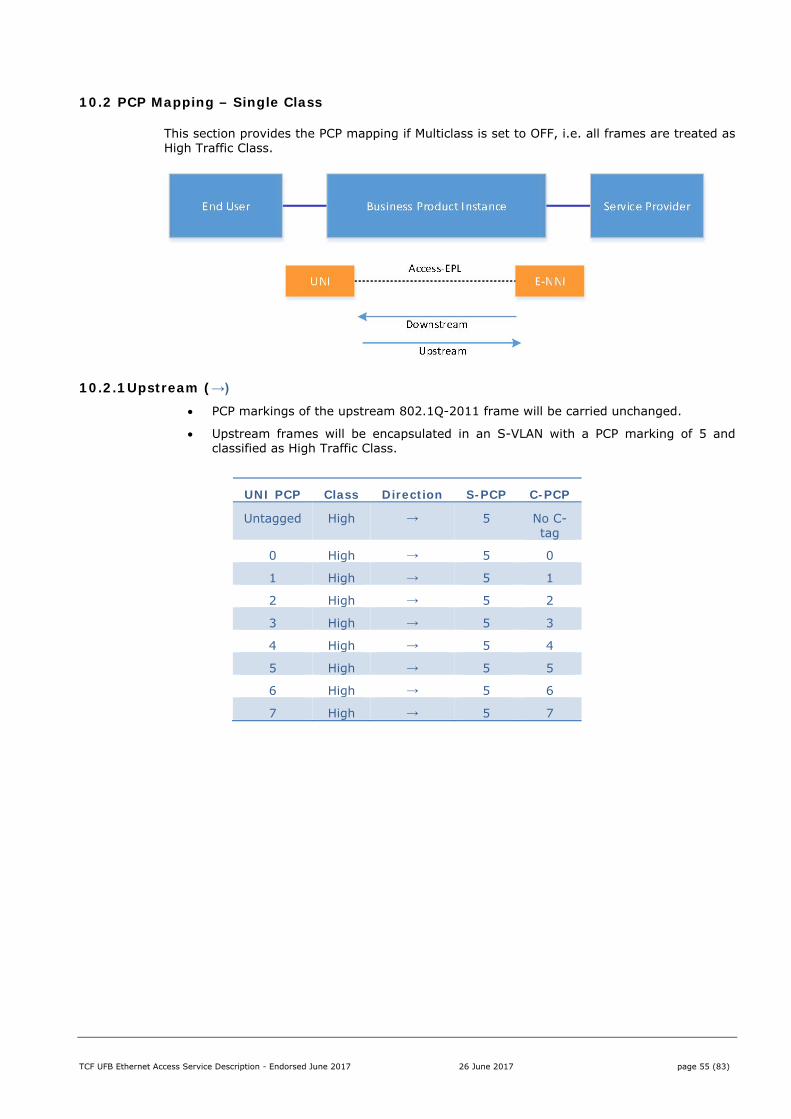
TCF UFB Ethernet Access Service Description - Endorsed June 2017 26 June 2017 page 55 (83)
10.2 PCP Mapping – Single Class
This section provides the PCP mapping if Multiclass is set to OFF, i.e. all frames are treated as High Traffic Class.
10.2.1 Upstream (→)
PCP markings of the upstream 802.1Q-2011 frame will be carried unchanged.
Upstream frames will be encapsulated in an S-VLAN with a PCP marking of 5 and classified as High Traffic Class.
UNI PCP Class Direction S-PCP C-PCP
Untagged High → 5 No C-tag
0 High → 5 0
1 High → 5 1
2 High → 5 2
3 High → 5 3
4 High → 5 4
5 High → 5 5
6 High → 5 6
7 High → 5 7
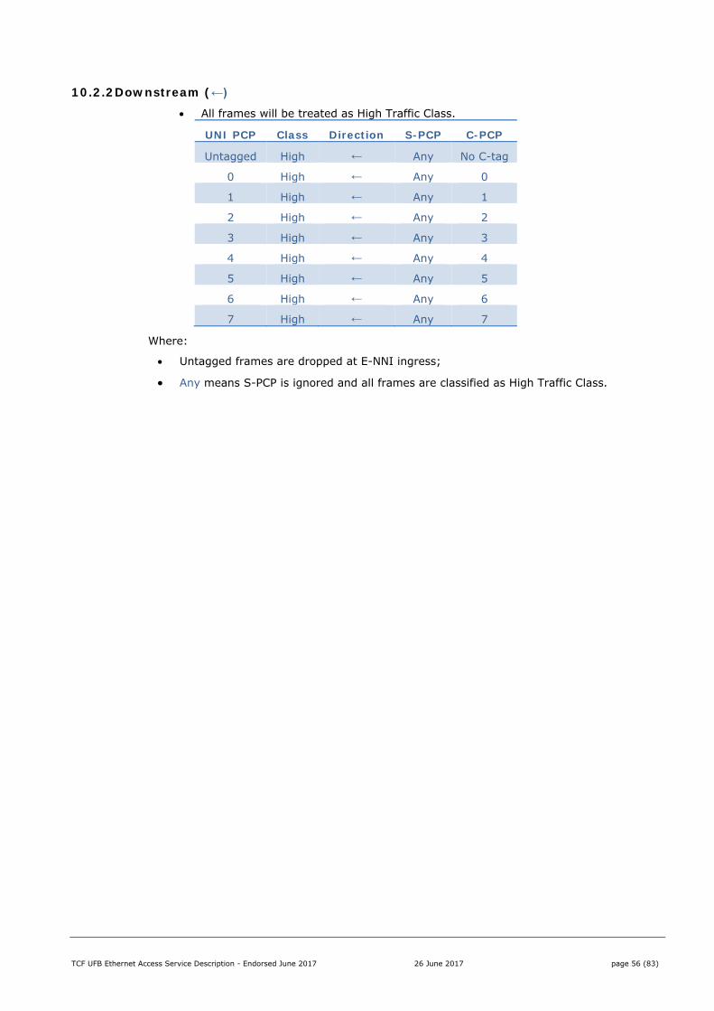
TCF UFB Ethernet Access Service Description - Endorsed June 2017 26 June 2017 page 56 (83)
10.2.2 Downstream (←)
All frames will be treated as High Traffic Class.
UNI PCP Class Direction S-PCP C-PCP
Untagged High ← Any No C-tag
0 High ← Any 0
1 High ← Any 1
2 High ← Any 2
3 High ← Any 3
4 High ← Any 4
5 High ← Any 5
6 High ← Any 6
7 High ← Any 7
Where:
Untagged frames are dropped at E-NNI ingress;
Any means S-PCP is ignored and all frames are classified as High Traffic Class.

TCF UFB Ethernet Access Service Description - Endorsed June 2017 26 June 2017 page 57 (83)
10.3 PCP Mapping – Multiclass
This section provides the PCP mapping if Multiclass is set to ON, i.e. both High and Low Traffic Classes are supported.
10.3.1 Upstream (→)
PCP marking of upstream 802.1Q-2011 frames received at the UNI will be carried unchanged.
Upstream frames with a PCP marking of 1, 2, 3, 4, 5, 6 and 7 will be encapsulated in an S-VLAN with a PCP marking of 5 and classified as High Traffic Class.
Upstream frames with a PCP marking of 0 will be encapsulated in an S-VLAN with a PCP marking of 0 and classified as Low Traffic Class
Upstream frames that are received untagged at the UNI will be encapsulated in an S-VLAN with a PCP marking of 0 and classified as Low Traffic Class.
UNI PCP Class Direction S-PCP C-PCP
Untagged Low → 0 No C-tag
0 Low → 0 0
1 High → 5 1
2 High → 5 2
3 High → 5 3
4 High → 5 4
5 High → 5 5
6 High → 5 6
7 High → 5 7
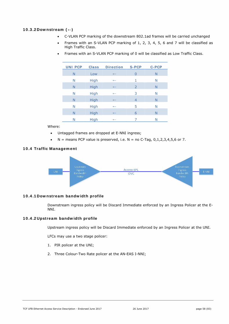
TCF UFB Ethernet Access Service Description - Endorsed June 2017 26 June 2017 page 58 (83)
10.3.2 Downstream (←)
C-VLAN PCP marking of the downstream 802.1ad frames will be carried unchanged
Frames with an S-VLAN PCP marking of 1, 2, 3, 4, 5, 6 and 7 will be classified as High Traffic Class.
Frames with an S-VLAN PCP marking of 0 will be classified as Low Traffic Class.
UNI PCP Class Direction S-PCP C-PCP
N Low ← 0 N
N High ← 1 N
N High ← 2 N
N High ← 3 N
N High ← 4 N
N High ← 5 N
N High ← 6 N
N High ← 7 N
Where:
Untagged frames are dropped at E-NNI ingress;
N = means PCP value is preserved, i.e. N = no C-Tag, 0,1,2,3,4,5,6 or 7.
10.4 Traffic Management
10.4.1 Downstream bandwidth profile
Downstream ingress policy will be Discard Immediate enforced by an Ingress Policer at the E-NNI.
10.4.2 Upstream bandwidth profile
Upstream ingress policy will be Discard Immediate enforced by an Ingress Policer at the UNI.
LFCs may use a two stage policer:
1. PIR policer at the UNI;
2. Three Colour-Two Rate policer at the AN-EAS I-NNI;
TCF UFB Ethernet Access Service Description - Endorsed June 2017 26 June 2017 page 59 (83)
10.5 Service Attributes for Business
The tables below show the minimum service attributes and valid attribute value ranges for the Business product.
10.5.1 UNI –Access-EPL
Valid UNI attribute options for an Access-EVPL or E-Tree are shown in the table below:
Service attribute Valid attribute values
UNI Identifier <string> generated by OSS/BSS
Physical Medium 100Base-Tx/1000Base-T
Speed 100/1000 Mbit/s
Mode Full Duplex
MAC Layer IEEE 802.3-2012
UNI MTU Size 2000 bytes
Service Multiplexing No
Bundling No
All to One Bundling Yes
CE-VLAN ID for untagged and priority tagged Service Frames
Transparent. All service frames mapped to one OVC
Maximum number of OVCs 1
Ingress Bandwidth Profile Per UNI Not Allowed
Egress Bandwidth Profile Per UNI Not Allowed
L2CP Processing Not Allowed

TCF UFB Ethernet Access Service Description - Endorsed June 2017 26 June 2017 page 60 (83)
10.5.2 OVC attributes- Access-EPL
Service attribute Valid attribute values
UNI OVC ID <string> generated by OSS/BSS
CE-VLAN ID/OVC Map Transparent. All service frames at the UNI mapped to one OVC
Access bandwidth GigE
Note: A logical Access Rate is defined, e.g.100 Mbps (single class) or 200 Mbps (Multiclass), which may be less than the UNI physical interface.
Ingress Bandwidth Profile Per OVC Subject to commercial arrangements
Ingress Bandwidth Profile per CoS Identifier
Subject to commercial agreement
Maximum number of MAC addresses At least 64
OVC Type Point-to-Point
OVC ID <string> generated by OSS/BSS
UNI List <string> generated by OSS/BSS
Maximum Number of UNIs 1
Maximum Number of OVCs at each NNI 4093
OVC MTU size 2000 byte
CE-VLAN ID Preservation Yes
CE-VLAN CoS Preservation Yes
Unicast Service Frame Delivery Unconditional to within service CIR/EIR
Multicast Service Frame Delivery Unconditional to within service CIR/EIR
Broadcast Service Frame Delivery Unconditional to within service CIR/EIR
Layer 2 Control Protocols Processing Discard IEEE 802.3x Mac Control Frames (PAUSE)
Discard Link Aggregation Control Frames
Discard IEEE 802.1x Port Authentication
Discard Generic Attribute Registration Protocol (GARP)
Discard Spanning Tree Protocol (STP)
Discard LLDP
Discard Link OAM
Discard E-LMI frames
TCF UFB Ethernet Access Service Description - Endorsed June 2017 26 June 2017 page 61 (83)
10.5.3 Other Attributes
Service attribute Valid attribute values
Ethernet Protocols Transparent. All service frames at the UNI mapped to one OVC
Untagged Frames Transparent.
Default OVC No
Fibre Network Resiliency Yes for businesses within defined areas and for priority users.
Diverse Ring/Single Lead-in Yes for businesses within defined areas where requested.
Layer 2 Resiliency No
Number of UNIs at premises 4
Number of VLANs per OVC Transparent. All service frames at the UNI mapped to one OVC
Additional Parameters MAC transparency
No MAC Filtering except where required to restrict L2CP
LFC selects E-NNI S-VID mapping
TCF UFB Ethernet Access Service Description - Endorsed June 2017 26 June 2017 page 62 (83)
11 Business Premium
The Business Premium product supports a single Access-EPL services per UNI and is targeted at the head office or Corporate markets.
The Business Premium product is optimised to support Retail Service Providers offering either Layer 2 or Layer 3 solutions.
11.1 Key Features
Business supports the following features:
Feature Values Number of OVCs 1 per UNI
E-NNI Tagging ON
MTU 9100 bytes
OVC Bandwidth profile Low Not used High CIR/CBS/EIR/EBS
UNI VLAN ID VLAN transparent
Handover Mapping Mapped per Product Instance
E-NNI VLAN ID One SVID per Access-EPL OVC
MAC Addresses 128
11.1.1 Number of OVCs
The Business Access-EPL service supports up to 1 Access-EPL per UNI.
11.1.2 E-NNI Tagging
E-NNI Tagging is always ON.
Upstream Frames presented at the E-NNI are 802.1ad single or double-tagged with a unique S-VID per Access-EVPL.
Downstream frames submitted at the E-NNI must be 802.1ad single or double-tagged with the Access-EPL S-VID.
LFCs will offer Q-in-Q as an alternative format and may offer additional Ethertypes.
11.1.3 MTU
The Maximum Transmission Unit for the Business Premium Access-EPL is 9100 bytes. This includes frame header and checksum but excludes preamble frame delimiters and inter-frame gaps.
This includes the S-tag inserted by the network so the MTU at the UNI is 9096 bytes.

TCF UFB Ethernet Access Service Description - Endorsed June 2017 26 June 2017 page 63 (83)
11.1.4 OVC Bandwidth profile Attribute Values Low Class of Service
Not used
High Class of Service
CIR = Committed Information Rate = Headline Rate CBS = Committed Burst Size EIR = 0 Mbps EBS = 0 kB
All Colour Blind (One traffic class) Coupling Flag N/A
11.1.5 UNI VLAN ID The Access-EPL is VLAN transparent, i.e. the service supports untagged and single tagged frames at the UNI.
11.1.6 Handover Mapping
Each Access-EPL is mapped to a handover specified by the Retail Service Provider at time of ordering.
Access-EPLs can be moved from the initial handover to optimise E-NNI efficiency and overbooking. This is done by a modify service request.
11.1.7 E-NNI VLAN ID
The E-NNI S-VID VLAN ID is allocated by the LFC.
The Retail Service Provider can specify an S-VID whitelist for the E-NNI. If an S-VID whitelist is specified then the LFC will assign the E-NNI S-VID out of this whitelist.
The C-tag is carried transparently by the Access-EPL:
Untagged 802.1Q-2011 Ethernet frames at the UNI are delivered as single S-tagged 802.1ad Ethernet frames at the E-NNI.
Single tagged 802.1Q-2011 Ethernet frames at the UNI are delivered as double tagged 802.1ad Ethernet frames at the E-NNI with the CE-tag preserved.
Single S-tagged 802.1ad frames at the E-NNI are delivered as untagged 802.1Q-2011 Ethernet frames at the UNI
Double tagged 802.1ad Ethernet frames at the E-NNI are delivered as single tagged 802.1Q-2011 Ethernet frames at the UNI with the C-tag preserved.
11.1.8 MAC Addresses
Business Premium supports at least 128 MAC addresses at the End User site, each capable of using all Traffic Classes.
Note that some LFCs may have Business Premium offers with unlimited MAC addresses, as described in the individual LFC Service Descriptions.
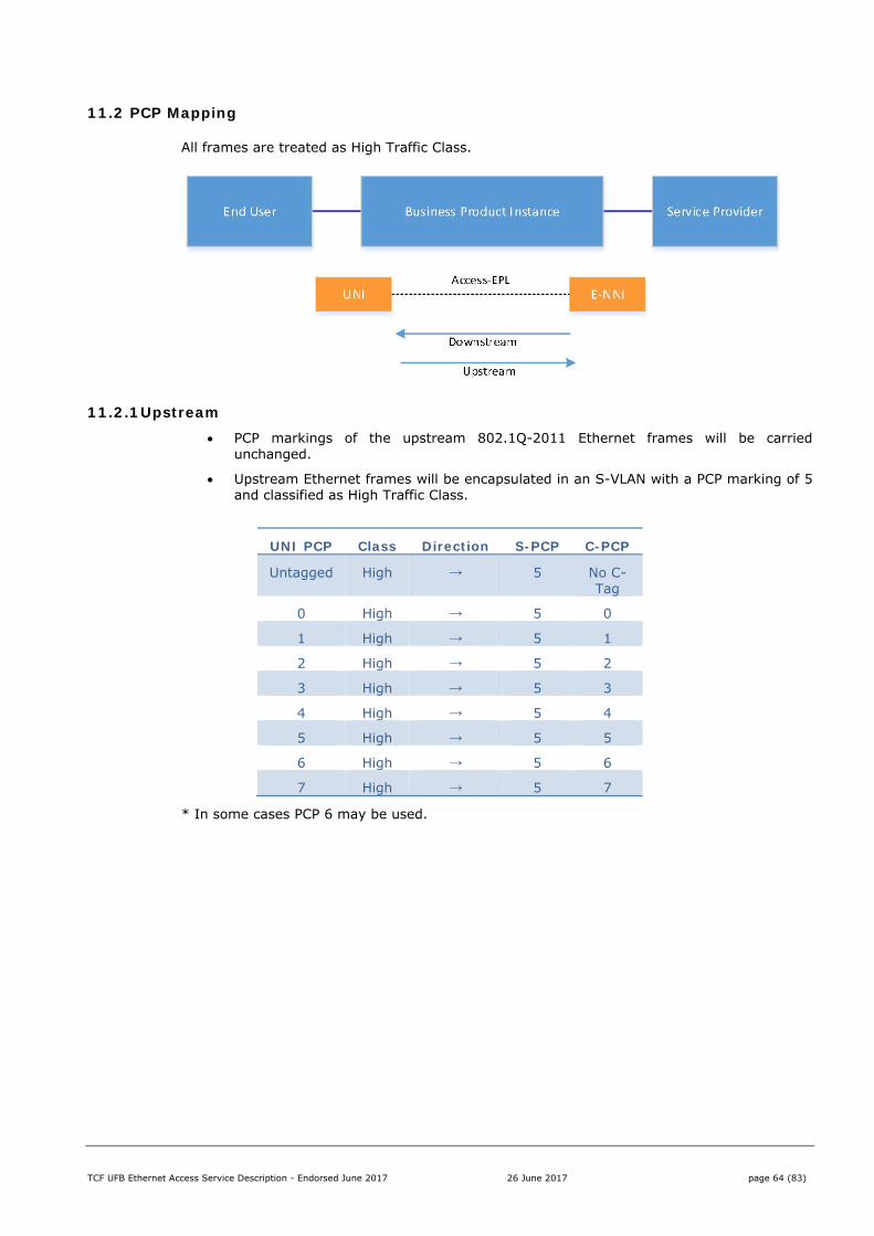
TCF UFB Ethernet Access Service Description - Endorsed June 2017 26 June 2017 page 64 (83)
11.2 PCP Mapping
All frames are treated as High Traffic Class.
11.2.1 Upstream PCP markings of the upstream 802.1Q-2011 Ethernet frames will be carried
unchanged.
Upstream Ethernet frames will be encapsulated in an S-VLAN with a PCP marking of 5 and classified as High Traffic Class.
UNI PCP Class Direction S-PCP C-PCP
Untagged High → 5 No C-Tag
0 High → 5 0
1 High → 5 1
2 High → 5 2
3 High → 5 3
4 High → 5 4
5 High → 5 5
6 High → 5 6
7 High → 5 7
* In some cases PCP 6 may be used.
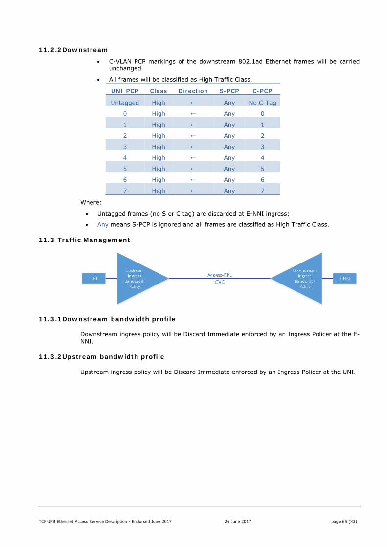
TCF UFB Ethernet Access Service Description - Endorsed June 2017 26 June 2017 page 65 (83)
11.2.2 Downstream C-VLAN PCP markings of the downstream 802.1ad Ethernet frames will be carried
unchanged
All frames will be classified as High Traffic Class.
UNI PCP Class Direction S-PCP C-PCP
Untagged High ← Any No C-Tag
0 High ← Any 0
1 High ← Any 1
2 High ← Any 2
3 High ← Any 3
4 High ← Any 4
5 High ← Any 5
6 High ← Any 6
7 High ← Any 7
Where:
Untagged frames (no S or C tag) are discarded at E-NNI ingress;
Any means S-PCP is ignored and all frames are classified as High Traffic Class.
11.3 Traffic Management
11.3.1 Downstream bandwidth profile
Downstream ingress policy will be Discard Immediate enforced by an Ingress Policer at the E-NNI.
11.3.2 Upstream bandwidth profile
Upstream ingress policy will be Discard Immediate enforced by an Ingress Policer at the UNI.
TCF UFB Ethernet Access Service Description - Endorsed June 2017 26 June 2017 page 66 (83)
11.4 Service Attributes for Business Premium
The tables below show the minimum service attributes and valid attribute value ranges for the Business Premium product.
11.4.1 UNI –Access-EPL
Service attribute Valid attribute values
UNI Identifier OSS/BSS
Physical Medium 100/1000Base-T / 1000 Base LX / 1000 Base SX / 10GBase-T / 10GBase-SR / 10GBase-LR / 1000 Base BX
Speed 100 Mbit/S, 1000 Mbit/s, 10Gbit/s
Mode Full Duplex
MAC Layer IEEE 802.3-2012
UNI MTU Size 9100 bytes
Service Multiplexing No
Bundling No
All to One Bundling Yes
CE-VLAN ID for untagged and priority tagged Service Frames
Transparent. All service frames mapped to one OVC
Maximum number of OVCs 1
Ingress Bandwidth Profile Per UNI Not Allowed
Egress Bandwidth Profile Per UNI Not Allowed
L2CP Processing See OVC table
Note that not all Physical mediums will be available at all locations.
TCF UFB Ethernet Access Service Description - Endorsed June 2017 26 June 2017 page 67 (83)
11.4.2 OVC attributes - Access-EPL Service attribute Valid attribute values
UNI OVC ID <string> generated by OSS/BSS
CE-VLAN ID/OVC Map Transparent. All service frames at the UNI mapped to one OVC
Access bandwidth Subject to commercial arrangements
Ingress Bandwidth Profile Per OVC Subject to commercial arrangements
Ingress Bandwidth Profile per CoS Identifier
EIR = 0, CIR > 0
Maximum number of MAC addresses 128. Individual LFC offers may offer unlimited.
OVC Type Point-to-Point
OVC ID Access-EPL-[Retail Service Provider ID]-123 OSS/BSS
UNI List OSS/BSS
Maximum Number of UNIs 1
Maximum Number of OVCs at each NNI 4093
OVC MTU size 9100 byte
CE-VLAN ID Preservation Yes
CE-VLAN CoS Preservation Yes
Unicast Service Frame Delivery Unconditional to within service CIR
Multicast Service Frame Delivery Unconditional to within service CIR
Broadcast Service Frame Delivery Unconditional to within service CIR
Layer 2 Control Protocols Processing Discard IEEE 802.3x Mac Control Frames (PAUSE)
Discard Link Aggregation Control Frames
Pass IEEE 802.1x Port Authentication
Pass Generic Attribute Registration Protocol (GARP)
Pass Spanning Tree Protocol (STP)
Pass LLDP
Discard Link OAM
Pass E-LMI frames
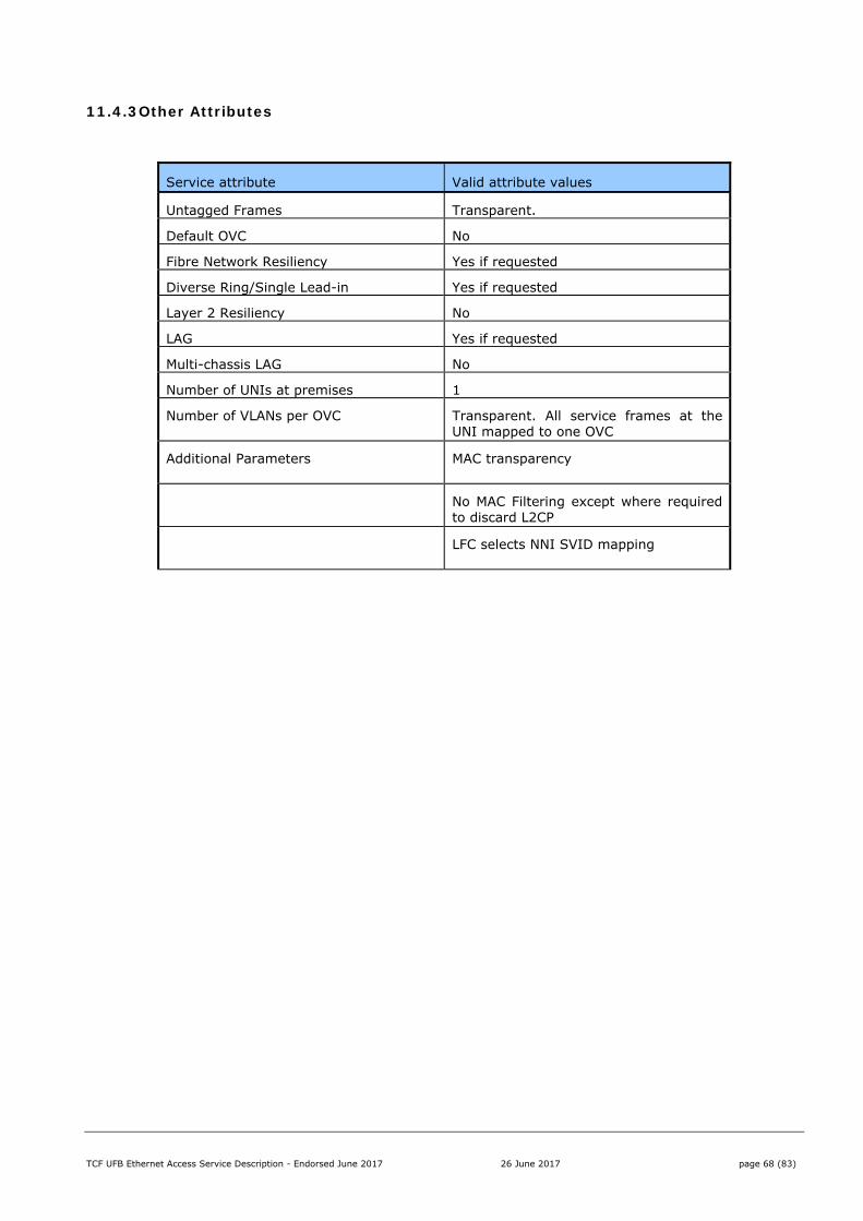
TCF UFB Ethernet Access Service Description - Endorsed June 2017 26 June 2017 page 68 (83)
11.4.3 Other Attributes
Service attribute Valid attribute values
Untagged Frames Transparent.
Default OVC No
Fibre Network Resiliency Yes if requested
Diverse Ring/Single Lead-in Yes if requested
Layer 2 Resiliency No
LAG Yes if requested
Multi-chassis LAG No
Number of UNIs at premises 1
Number of VLANs per OVC Transparent. All service frames at the UNI mapped to one OVC
Additional Parameters MAC transparency
No MAC Filtering except where required to discard L2CP
LFC selects NNI SVID mapping

TCF UFB Ethernet Access Service Description - Endorsed June 2017 26 June 2017 page 69 (83)
12 Ethernet Multicast Access (EMA) Product
The Ethernet Multicast Access (EMA) product provides a multicast enabled layer 2 service optimised for Mass Market media broadcast services.
The EMA service is a Layer 2 service that includes some Layer 3 inspection.
The EMA product requires tight coupling with the Retail Service Provider content solution and thus each instance of the EMA solution will be unique. This section describes the building blocks used by the LFC and Retail Service Providers to create such a solution, noting that the actual attributes and values used will be specific to each solution.
12.1.1 EMA Construct The Ethernet Multicast Access consists of two Product Components:
1. The Multicast Domain; and
2. The Multicast Connection.
A Multicast Domain supports the simultaneous transmission of a number of media streams. Traffic is automatically replicated throughout the domain as individual End Users join or leave the individual streams.
A Multicast Connection allows an End User to connect to the Multicast Domain and join one or more Multicast streams through IGMP ‘Join’ and ‘Leave’ and MLD equivalent messages.
The Multicast Connection can either be delivered as:
A separate vlan to an Access-EVPL; or
Combined with an Access-EVPL on a single vlan (Access-EVPL binding).
Figure 22: Multicast Connection delivered with separate VLAN
In this case the Multicast Connection can be delivered on the same or different UNI as the (optional) Access-EVPL.
TCF UFB Ethernet Access Service Description - Endorsed June 2017 26 June 2017 page 70 (83)
Figure 23: Multicast Connection with Access-EVPL binding
12.1.2 Mass Market TV Services The EMA service is intended to be used for mass market TV, and is based on the MEF EVP-Tree service construct and the BBF Multicast requirements in chapter 6 of TR-101. It is designed to be used by Retail Service Providers as a Multicast delivery mechanism for Broadcast TV services.
Each solution should be designed based on the intended end-user experience to ensure that the viewer has a good television experience.
12.1.3 Exclusions
It is assumed that Layer 3 multicast mechanisms (e.g. PIM/SM) are not part of the LFC network functionality.
IGMP Control Plane Interoperability
12.1.4 EMA for Mass Market TV services
The EMA service provides point-to-multipoint connectivity between one NNI and one or more UNI as shown in the diagram below. The NNI is known as the “root” and ingress service frames can be forwarded to some or all UNIs. The UNI is known as a “leaf” and ingress service frames can only be forwarded to the root i.e. there will be no connectivity between UNIs.
The EMA service is implemented as a separate service instance to the point-to-point ELA (Ethernet Line Access) service although it can share the same physical UNI and NNI interfaces as ELA services.
Figure 24: EMA for Mass Market TV Services

TCF UFB Ethernet Access Service Description - Endorsed June 2017 26 June 2017 page 71 (83)
TCF UFB Ethernet Access Service Description - Endorsed June 2017 26 June 2017 page 72 (83)
12.1.5 VLAN Model
The EMA service will use a dedicated N:1 multicast VLAN model as described in section 6.2 of TR-101. The EMA service will be identified at the NNI with a VLAN_ID. The EMA service can share a UNI with other services using CE-VLAN ID to identify each individual service instance. Provided a Retail Service Provider requests it, an EMA and an Access-EPL service can be combined onto the same CE-VLAN ID at the UNI to simplify VLAN requirements in the customer equipment.
12.1.6 Frame Delivery Downstream Direction:
Frame delivery for multicast traffic in the downstream direction is controlled by a Layer 3 control plane e.g. IGMP or MLD. At the NNI, all properly formatted ingress frames with a multicast destination MAC address are flooded to the UNIs which have requested membership of that specific Multicast group.
At the NNI, Unicast ingress frames are discarded.
Upstream Direction:
At the UNI, the only ingress frames that are mapped to the EMA service are Layer 3 control messages.
Ingress frames received at a UNI are not delivered to another UNI.
12.1.7 IGMP and MLD Support
The EMA service will support IGMP v2 (RFC2236) and v3 (RFC3376) for IPv4 through the implementation of IGMP snooping.
The EMA service will support MLD v2 for IPV6 (RFC3810) through the implementation of MLD snooping.
The EMA service should implement the recommendations in “Considerations for Internet Group Management Protocol (IGMP) and MLD Snooping Switches” (RFC4541).
IGMP and MLD include “source filtering”, which enables a network to use the source IP address of a multicast frame to determine frame forwarding.
The flooding of Ethernet Multicast Frames within an EMA service instance is controlled by the use of an IGMP/MLD control plane. The IGMP/MLD control plane uses the snooping function to monitor IGMP and MLD traffic and adjust replication filters so that frames are only delivered to those UNI that have specifically requested membership to that multicast group.
IGMP is an IPv4 specific protocol. MLD is an IPv6 specific protocol. The EMA service must ensure that the IGMP snooping function does not disable IPv6 multicast functionality and that the MLD snooping function does not disable IPv4 Multicast functionality.
All downstream and upstream IGMP and MLD messages used to control membership of groups within an EMA service instance are transported within the VLAN associated with that EMA service instance.
12.1.8 Optimising the TV End User Experience
It is recommended that the Retail Service Provider uses fast channel change technology, although it is acknowledged there is no technical standard established for this technology.
The solution should be optimised based on the end-user experience to ensure that the viewer has a rapid and smooth channel change experience.
TCF UFB Ethernet Access Service Description - Endorsed June 2017 26 June 2017 page 73 (83)
12.2 Key Features
EMA supports the following features, although not all will be used for each solution.
Component Feature Values
Connection Traffic Class High (default)
Connection UNI Tagging ON/OFF
Connection UNI VLAN ID One per Multicast Connection
Connection MTU 2000 bytes
Connection Access-EVPL Binding Yes/No
Connection Number of Channels Typically ≤ 6
Connection Bandwidth Profile Mbps
Domain Number of Channels A number agreed per solution, e.g. 120.
Domain Bandwidth per Channel Mbps
Domain Aggregate Bandwidth Profile Mbps
Domain E-NNI VLAN ID Agreed per solution
Domain E-NNI Mapping Fixed per Coverage area
Each Multicast solution will only implement the features and attribute values appropriate for the particular solution.
12.2.1 Multicast Connection: Traffic Class
The default Traffic Class for Multicast is High Traffic Class. However this may not be suitable for all Multicast Solutions and it is possible a custom Traffic Class will be provided, by agreement between the LFC and the Retail Service Provider.
12.2.2 Multicast Connection: UNI Tagging
Note this feature only applies if Access-EVPL binding is OFF.
Attribute Values
On Default option. Supports 802.1Q-2011 Ethernet frames at the UNI. Untagged frames will be tagged and classified as per the defined multicast connection traffic class.
Off Supports 802.1Q-2011 Ethernet frames at the UNI. Tagging is removed downstream Untagged frames will be tagged and classified as per the defined multicast connection traffic class.
A UNI with multiple OVCs terminating must have UNI tagging set to ON. However it is possible that one OVC can be set to untagged. This would be considered an extension to this standard.
12.2.3 Multicast Connection: UNI VLAN ID
The VLAN ID per Multicast Connection per offer will be agreed between the Retail Service Provider and the LFC. It will remain static per offer to allow CPE (RGW/BGW) to be preconfigured
If Access-EVPL Binding is set to ON then the Multicast Connection VLAN ID will be inherited from the Access-EVPL.
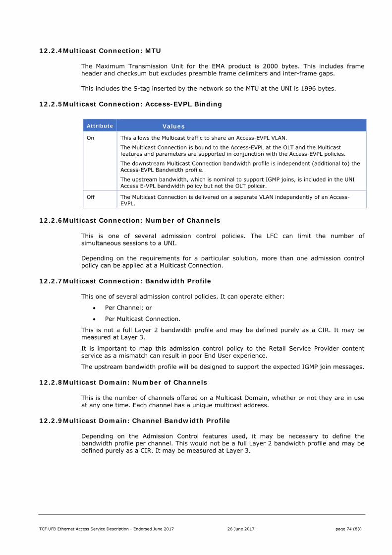
TCF UFB Ethernet Access Service Description - Endorsed June 2017 26 June 2017 page 74 (83)
12.2.4 Multicast Connection: MTU
The Maximum Transmission Unit for the EMA product is 2000 bytes. This includes frame header and checksum but excludes preamble frame delimiters and inter-frame gaps.
This includes the S-tag inserted by the network so the MTU at the UNI is 1996 bytes.
12.2.5 Multicast Connection: Access-EVPL Binding
Attribute Values
On This allows the Multicast traffic to share an Access-EVPL VLAN.
The Multicast Connection is bound to the Access-EVPL at the OLT and the Multicast features and parameters are supported in conjunction with the Access-EVPL policies.
The downstream Multicast Connection bandwidth profile is independent (additional to) the Access-EVPL Bandwidth profile.
The upstream bandwidth, which is nominal to support IGMP joins, is included in the UNI Access E-VPL bandwidth policy but not the OLT policer.
Off The Multicast Connection is delivered on a separate VLAN independently of an Access-EVPL.
12.2.6 Multicast Connection: Number of Channels
This is one of several admission control policies. The LFC can limit the number of simultaneous sessions to a UNI.
Depending on the requirements for a particular solution, more than one admission control policy can be applied at a Multicast Connection.
12.2.7 Multicast Connection: Bandwidth Profile
This one of several admission control policies. It can operate either:
Per Channel; or
Per Multicast Connection.
This is not a full Layer 2 bandwidth profile and may be defined purely as a CIR. It may be measured at Layer 3.
It is important to map this admission control policy to the Retail Service Provider content service as a mismatch can result in poor End User experience.
The upstream bandwidth profile will be designed to support the expected IGMP join messages.
12.2.8 Multicast Domain: Number of Channels
This is the number of channels offered on a Multicast Domain, whether or not they are in use at any one time. Each channel has a unique multicast address.
12.2.9 Multicast Domain: Channel Bandwidth Profile
Depending on the Admission Control features used, it may be necessary to define the bandwidth profile per channel. This would not be a full Layer 2 bandwidth profile and may be defined purely as a CIR. It may be measured at Layer 3.

TCF UFB Ethernet Access Service Description - Endorsed June 2017 26 June 2017 page 75 (83)
12.2.10 Multicast Domain: Aggregate Bandwidth Profile
This is the maximum aggregate bandwidth that is supported across the Coverage Area. It is the responsibility of the Retail Service Provider to ensure this bandwidth is not exceeded or random frame drops will occur.
This policy may or may not be a full layer 2 bandwidth profile and will be configured to best match the Retail Service Provider’s content.
12.2.11 Multicast Domain: E-NNI VLAN ID
The E-NNI VLAN ID is allocated by the LFC.
The Retail Service Provider can specify an S-VID whitelist for the E-NNI. If an S-VID whitelist is specified then the LFC will assign the E-NNI S-VID out of this whitelist.
12.2.12 Multicast Domain: E-NNI Mapping
There is a single E-NNI per Coverage Area associated with EMA per Domain.
This E-NNI can be shared with other UFB services, although that may not be desirable.
12.3 PCP Mapping
This assumes High Traffic Class is used for Multicast. If a custom class is used then PCP values will be different.
12.3.1 Upstream If Access-EVPL Binding is set to ON then the Access-EVPL PCP settings will apply.
If Access-EVPL Binding is set to OFF then
If the UNI is set to tagged then Frames with 802.1Q-2011 PCP tag of 5 and contain IGMP Join messages will be classified as High Traffic Class;
If the UNI is set to untagged then untagged frames containing IGMP Join messages will be classified as High Traffic Class;
All other frames will be discarded;
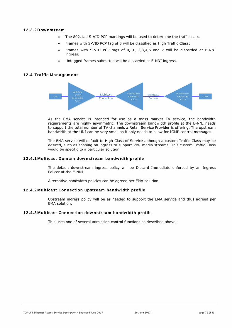
TCF UFB Ethernet Access Service Description - Endorsed June 2017 26 June 2017 page 76 (83)
12.3.2 Downstream The 802.1ad S-VID PCP markings will be used to determine the traffic class.
Frames with S-VID PCP tag of 5 will be classified as High Traffic Class;
Frames with S-VID PCP tags of 0, 1, 2,3,4,6 and 7 will be discarded at E-NNI ingress;
Untagged frames submitted will be discarded at E-NNI ingress.
12.4 Traffic Management
As the EMA service is intended for use as a mass market TV service, the bandwidth requirements are highly asymmetric. The downstream bandwidth profile at the E-NNI needs to support the total number of TV channels a Retail Service Provider is offering. The upstream bandwidth at the UNI can be very small as it only needs to allow for IGMP control messages.
The EMA service will default to High Class of Service although a custom Traffic Class may be desired, such as shaping on ingress to support VBR media streams. This custom Traffic Class would be specific to a particular solution.
12.4.1 Multicast Domain downstream bandwidth profile
The default downstream ingress policy will be Discard Immediate enforced by an Ingress Policer at the E-NNI.
Alternative bandwidth policies can be agreed per EMA solution
12.4.2 Multicast Connection upstream bandwidth profile
Upstream ingress policy will be as needed to support the EMA service and thus agreed per EMA solution.
12.4.3 Multicast Connection downstream bandwidth profile
This uses one of several admission control functions as described above.
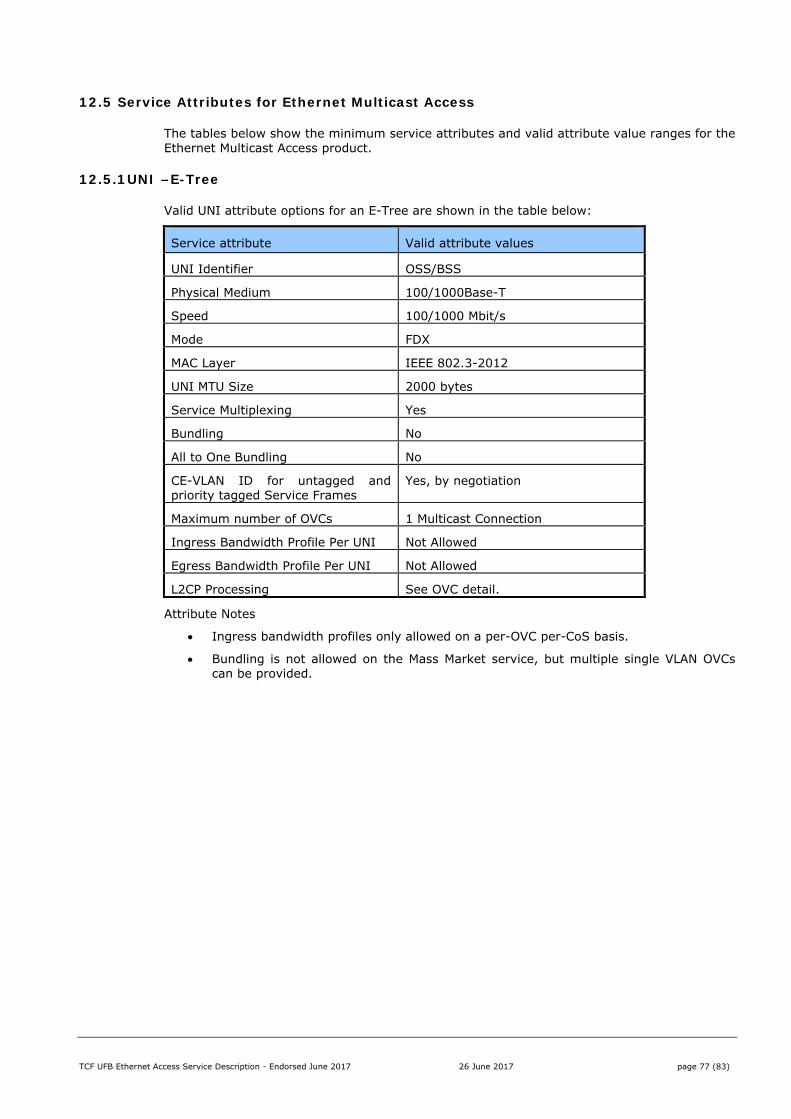
TCF UFB Ethernet Access Service Description - Endorsed June 2017 26 June 2017 page 77 (83)
12.5 Service Attributes for Ethernet Multicast Access
The tables below show the minimum service attributes and valid attribute value ranges for the Ethernet Multicast Access product.
12.5.1 UNI –E-Tree
Valid UNI attribute options for an E-Tree are shown in the table below:
Service attribute Valid attribute values
UNI Identifier OSS/BSS
Physical Medium 100/1000Base-T
Speed 100/1000 Mbit/s
Mode FDX
MAC Layer IEEE 802.3-2012
UNI MTU Size 2000 bytes
Service Multiplexing Yes
Bundling No
All to One Bundling No
CE-VLAN ID for untagged and priority tagged Service Frames
Yes, by negotiation
Maximum number of OVCs 1 Multicast Connection
Ingress Bandwidth Profile Per UNI Not Allowed
Egress Bandwidth Profile Per UNI Not Allowed
L2CP Processing See OVC detail.
Attribute Notes
Ingress bandwidth profiles only allowed on a per-OVC per-CoS basis.
Bundling is not allowed on the Mass Market service, but multiple single VLAN OVCs can be provided.
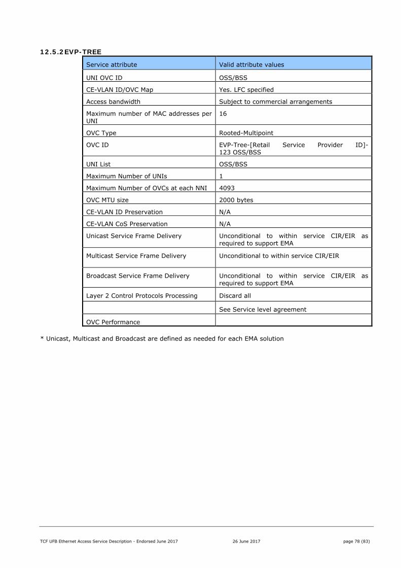
TCF UFB Ethernet Access Service Description - Endorsed June 2017 26 June 2017 page 78 (83)
12.5.2 EVP-TREE
Service attribute Valid attribute values
UNI OVC ID OSS/BSS
CE-VLAN ID/OVC Map Yes. LFC specified
Access bandwidth Subject to commercial arrangements
Maximum number of MAC addresses per UNI
16
OVC Type Rooted-Multipoint
OVC ID EVP-Tree-[Retail Service Provider ID]-123 OSS/BSS
UNI List OSS/BSS
Maximum Number of UNIs 1
Maximum Number of OVCs at each NNI 4093
OVC MTU size 2000 bytes
CE-VLAN ID Preservation N/A
CE-VLAN CoS Preservation N/A
Unicast Service Frame Delivery Unconditional to within service CIR/EIR as required to support EMA
Multicast Service Frame Delivery Unconditional to within service CIR/EIR
Broadcast Service Frame Delivery Unconditional to within service CIR/EIR as required to support EMA
Layer 2 Control Protocols Processing Discard all
See Service level agreement
OVC Performance
* Unicast, Multicast and Broadcast are defined as needed for each EMA solution
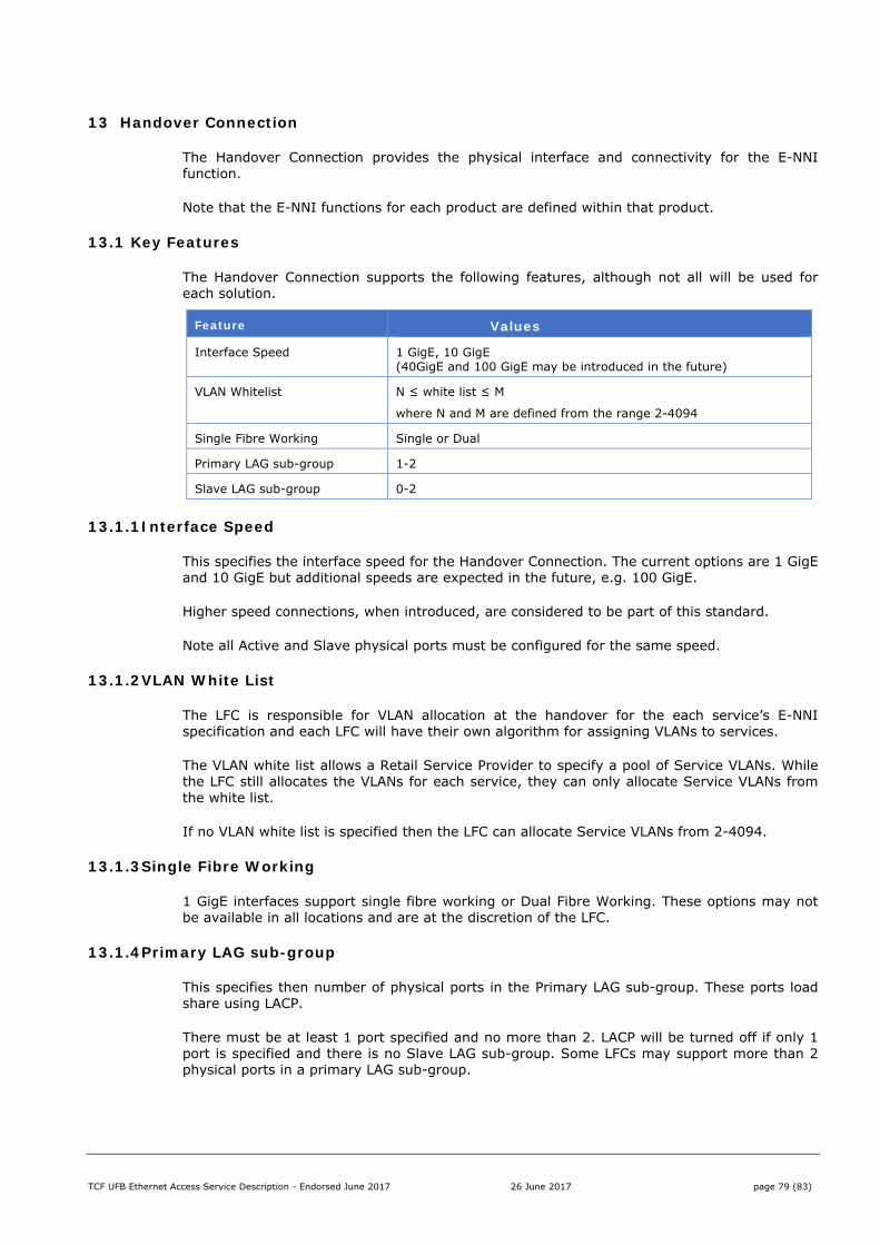
TCF UFB Ethernet Access Service Description - Endorsed June 2017 26 June 2017 page 79 (83)
13 Handover Connection
The Handover Connection provides the physical interface and connectivity for the E-NNI function.
Note that the E-NNI functions for each product are defined within that product.
13.1 Key Features
The Handover Connection supports the following features, although not all will be used for each solution.
Feature Values
Interface Speed 1 GigE, 10 GigE (40GigE and 100 GigE may be introduced in the future)
VLAN Whitelist N ≤ white list ≤ M
where N and M are defined from the range 2-4094
Single Fibre Working Single or Dual
Primary LAG sub-group 1-2
Slave LAG sub-group 0-2
13.1.1 Interface Speed
This specifies the interface speed for the Handover Connection. The current options are 1 GigE and 10 GigE but additional speeds are expected in the future, e.g. 100 GigE.
Higher speed connections, when introduced, are considered to be part of this standard.
Note all Active and Slave physical ports must be configured for the same speed.
13.1.2 VLAN White List
The LFC is responsible for VLAN allocation at the handover for the each service’s E-NNI specification and each LFC will have their own algorithm for assigning VLANs to services.
The VLAN white list allows a Retail Service Provider to specify a pool of Service VLANs. While the LFC still allocates the VLANs for each service, they can only allocate Service VLANs from the white list.
If no VLAN white list is specified then the LFC can allocate Service VLANs from 2-4094.
13.1.3 Single Fibre Working
1 GigE interfaces support single fibre working or Dual Fibre Working. These options may not be available in all locations and are at the discretion of the LFC.
13.1.4 Primary LAG sub-group
This specifies then number of physical ports in the Primary LAG sub-group. These ports load share using LACP.
There must be at least 1 port specified and no more than 2. LACP will be turned off if only 1 port is specified and there is no Slave LAG sub-group. Some LFCs may support more than 2 physical ports in a primary LAG sub-group.
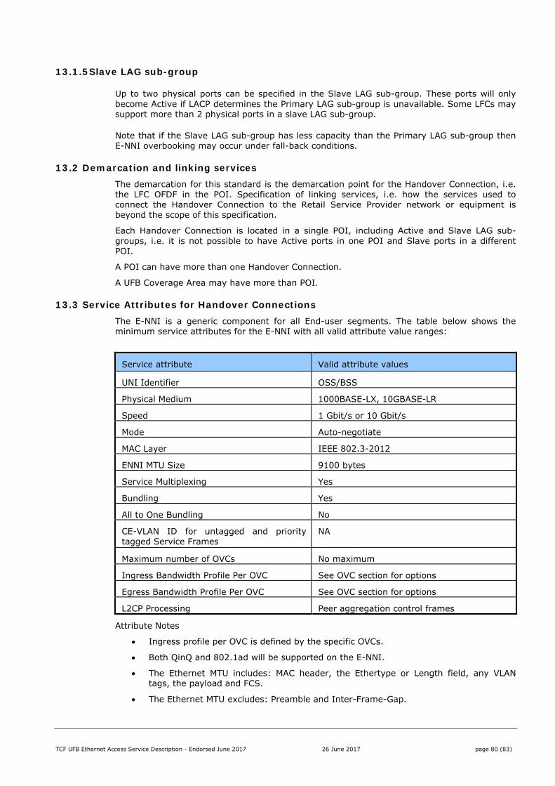
TCF UFB Ethernet Access Service Description - Endorsed June 2017 26 June 2017 page 80 (83)
13.1.5 Slave LAG sub-group
Up to two physical ports can be specified in the Slave LAG sub-group. These ports will only become Active if LACP determines the Primary LAG sub-group is unavailable. Some LFCs may support more than 2 physical ports in a slave LAG sub-group.
Note that if the Slave LAG sub-group has less capacity than the Primary LAG sub-group then E-NNI overbooking may occur under fall-back conditions.
13.2 Demarcation and linking services The demarcation for this standard is the demarcation point for the Handover Connection, i.e. the LFC OFDF in the POI. Specification of linking services, i.e. how the services used to connect the Handover Connection to the Retail Service Provider network or equipment is beyond the scope of this specification.
Each Handover Connection is located in a single POI, including Active and Slave LAG sub-groups, i.e. it is not possible to have Active ports in one POI and Slave ports in a different POI.
A POI can have more than one Handover Connection.
A UFB Coverage Area may have more than POI.
13.3 Service Attributes for Handover Connections The E-NNI is a generic component for all End-user segments. The table below shows the minimum service attributes for the E-NNI with all valid attribute value ranges:
Service attribute Valid attribute values
UNI Identifier OSS/BSS
Physical Medium 1000BASE-LX, 10GBASE-LR
Speed 1 Gbit/s or 10 Gbit/s
Mode Auto-negotiate
MAC Layer IEEE 802.3-2012
ENNI MTU Size 9100 bytes
Service Multiplexing Yes
Bundling Yes
All to One Bundling No
CE-VLAN ID for untagged and priority tagged Service Frames
NA
Maximum number of OVCs No maximum
Ingress Bandwidth Profile Per OVC See OVC section for options
Egress Bandwidth Profile Per OVC See OVC section for options
L2CP Processing Peer aggregation control frames
Attribute Notes
Ingress profile per OVC is defined by the specific OVCs.
Both QinQ and 802.1ad will be supported on the E-NNI.
The Ethernet MTU includes: MAC header, the Ethertype or Length field, any VLAN tags, the payload and FCS.
The Ethernet MTU excludes: Preamble and Inter-Frame-Gap.
TCF UFB Ethernet Access Service Description - Endorsed June 2017 26 June 2017 page 81 (83)
14 ANNEX 1 - References
[1] OFCOM Ethernet Active Line Access: Updated Technical Requirements, 3rd March 2009
[2] NICC ND 1642 Requirements for Ethernet Interconnect and Ethernet ALA, 2009-06
[3] Communications Alliance, Wholesale Service Definition Framework – Ethernet, Release 1, Dec. 2009
[4] MEF 6.1 Ethernet Services Definitions – Phase 2, April 2008
[5] MEF 10.2 Ethernet Services Attributes Phase 2, October 2009
[6] MEF 23 Class of Service Phase 1,
[7] MEF 26 External Network Interface (ENNI) – Phase 1, January 2010
[8] MEF 33 Access Ethernet Services (2012)
[9] Broadband Forum TR101 Migration to Ethernet-based DSL aggregation
[10] Broadband Forum TR156 Using GPON Access in the context of TR-101
[11] MEF 6.2 Ethernet Services Definition - Phase 3, August 2014
[12] MEF 10.3, Ethernet Services Attributes Phase 3, October 2013
[13] MEF 26.1 External Network to Network Interface (ENNI) – Phase 2, January 2012
TCF UFB Ethernet Access Service Description - Endorsed June 2017 26 June 2017 page 82 (83)
15 ANNEX 2 – FTTP Definitions
Term Definition
Access Ethernet Service (AES)
Ethernet service between the Access Node in the Central Office and the End-user premises provided by the AES-provider to the AES-user
AFS Access Fibre Service
ANTP Access Network Termination Point
AON (Active Optical Network)
Aa general term that describes any network configuration in which each end-user is connected to their own dedicated port on Retail Service Provider’s access/aggregation equipment in the Central Office, using a direct point-to-point physical connection
Backhaul Refers to backhaul within an LFC.
CO (Central Office) An environmentally controlled facility hosting active and passive telecommunications plant and infrastructure. The CO is a point of interconnect and co-location area for Retail Service Providers, who require access to the End-user premises serviced from the CO
Communal Infrastructure Being the network infrastructure in the Proposed Coverage Area which is deployed independently of any specific End User commitment and which is not located on End Users’ sites or premises.
Dark fibre Optical fibre physical infrastructure without any active equipment attached. Dark, as it has no source of light inherent in the network design.
End user specific infrastructure
Being the network infrastructure which is deployed specifically for an End User commitment and which may be located on End Users’ sites or premises.
End User-Network Interface (UNI)
The interface between the Network and the End-user at the customer premises
End-user Ultimate recipient of services provided over Dark fibre or ALA described in this document, including both residential consumers and business users
ETP (External Termination Point)
"The External Termination Point on the End User's premises is a suitable fibre termination facility located as an attachment to an external part of the building or structure located at the End User's premises. Specifically, the termination point will be the SC connector which plugs into the ONU or NTU inside the End User’s premises
Events Service failure
Fibre Concentration Point The FCP “aggregates” small fibre count cables into larger fibre count cables. The FCP function can occur in cabinets, pits or Pedestals.
FTTC Fibre to the Curb
FTTH Fibre to the Home
FTTN Fibre to the Node
FTTP Fibre to the Premises
ITP Internal Termination Point – as ETP, but located inside the premises
Layer “0’ The unofficial layer 0, not part of the actual OSI model, which is sometimes used to refer to the Physical media for OSI (such as dark fibre or copper cables), and sometimes also used to refer to ducts, poles and radio spectrum
Layer 1 The “Physical Layer”, of the OSI Model. The Physical Layer provides for transparent transmission of bitstreams between data link (layer 2) entities across physical connections
Layer 2 The “Datalink Layer”, of the OSI Model, which provides the functional and procedural means to transfer data between network entities and to detect and possibly correct errors that may occur in the Physical Layer
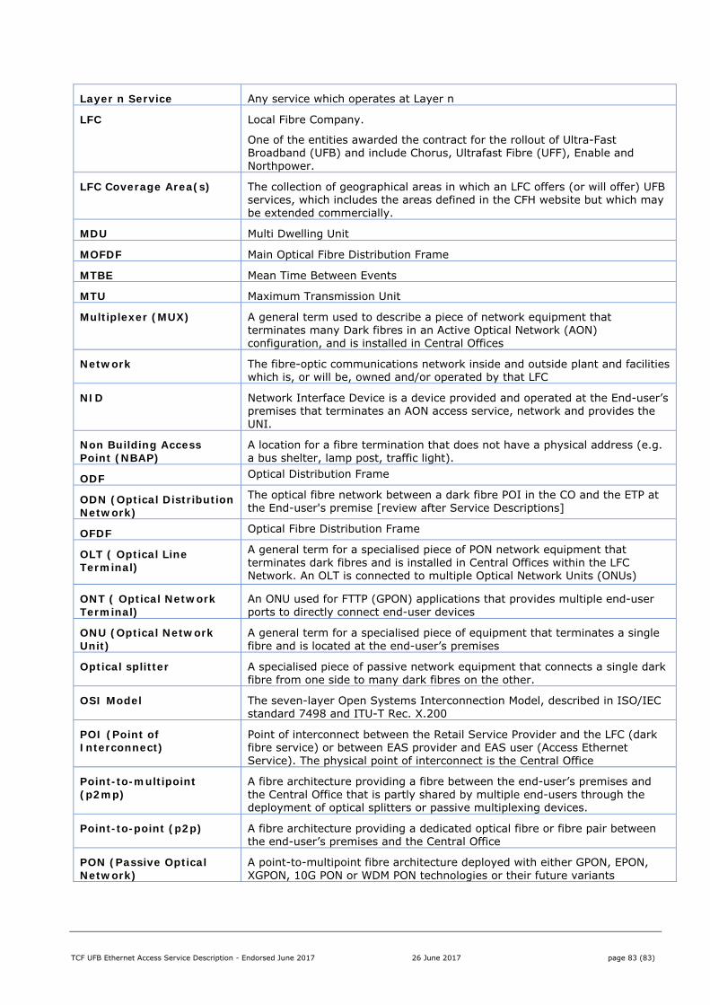
TCF UFB Ethernet Access Service Description - Endorsed June 2017 26 June 2017 page 83 (83)
Layer n Service Any service which operates at Layer n
LFC Local Fibre Company.
One of the entities awarded the contract for the rollout of Ultra-Fast Broadband (UFB) and include Chorus, Ultrafast Fibre (UFF), Enable and Northpower.
LFC Coverage Area(s) The collection of geographical areas in which an LFC offers (or will offer) UFB services, which includes the areas defined in the CFH website but which may be extended commercially.
MDU Multi Dwelling Unit
MOFDF Main Optical Fibre Distribution Frame
MTBE Mean Time Between Events
MTU Maximum Transmission Unit
Multiplexer (MUX) A general term used to describe a piece of network equipment that terminates many Dark fibres in an Active Optical Network (AON) configuration, and is installed in Central Offices
Network The fibre-optic communications network inside and outside plant and facilities which is, or will be, owned and/or operated by that LFC
NID Network Interface Device is a device provided and operated at the End-user’s premises that terminates an AON access service, network and provides the UNI.
Non Building Access Point (NBAP)
A location for a fibre termination that does not have a physical address (e.g. a bus shelter, lamp post, traffic light).
ODF Optical Distribution Frame
ODN (Optical Distribution Network)
The optical fibre network between a dark fibre POI in the CO and the ETP at the End-user's premise [review after Service Descriptions]
OFDF Optical Fibre Distribution Frame
OLT ( Optical Line Terminal)
A general term for a specialised piece of PON network equipment that terminates dark fibres and is installed in Central Offices within the LFC Network. An OLT is connected to multiple Optical Network Units (ONUs)
ONT ( Optical Network Terminal)
An ONU used for FTTP (GPON) applications that provides multiple end-user ports to directly connect end-user devices
ONU (Optical Network Unit)
A general term for a specialised piece of equipment that terminates a single fibre and is located at the end-user’s premises
Optical splitter A specialised piece of passive network equipment that connects a single dark fibre from one side to many dark fibres on the other.
OSI Model The seven-layer Open Systems Interconnection Model, described in ISO/IEC standard 7498 and ITU-T Rec. X.200
POI (Point of Interconnect)
Point of interconnect between the Retail Service Provider and the LFC (dark fibre service) or between EAS provider and EAS user (Access Ethernet Service). The physical point of interconnect is the Central Office
Point-to-multipoint (p2mp)
A fibre architecture providing a fibre between the end-user’s premises and the Central Office that is partly shared by multiple end-users through the deployment of optical splitters or passive multiplexing devices.
Point-to-point (p2p) A fibre architecture providing a dedicated optical fibre or fibre pair between the end-user’s premises and the Central Office
PON (Passive Optical Network)
A point-to-multipoint fibre architecture deployed with either GPON, EPON, XGPON, 10G PON or WDM PON technologies or their future variants
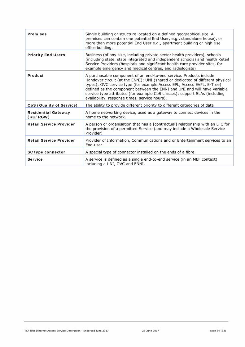
TCF UFB Ethernet Access Service Description - Endorsed June 2017 26 June 2017 page 84 (83)
Premises Single building or structure located on a defined geographical site. A premises can contain one potential End User, e.g., standalone house), or more than more potential End User e.g., apartment building or high rise office building.
Priority End Users Business (of any size, including private sector health providers), schools (including state, state integrated and independent schools) and health Retail Service Providers (hospitals and significant health care provider sites, for example emergency and medical centres, and radiologists)
Product A purchasable component of an end-to-end service. Products include: Handover circuit (at the ENNI); UNI (shared or dedicated of different physical types); OVC service type (for example Access EPL, Access EVPL, E-Tree) defined as the component between the ENNI and UNI and will have variable service type attributes (for example CoS classes); support SLAs (including availability, response times, service hours).
QoS (Quality of Service) The ability to provide different priority to different categories of data
Residential Gateway (RG/RGW)
A home networking device, used as a gateway to connect devices in the home to the network.
Retail Service Provider A person or organisation that has a [contractual] relationship with an LFC for the provision of a permitted Service (and may include a Wholesale Service Provider)
Retail Service Provider Provider of Information, Communications and or Entertainment services to an End-user
SC type connector A special type of connector installed on the ends of a fibre
Service A service is defined as a single end-to-end service (in an MEF context) including a UNI, OVC and ENNI.