Embed Size (px)
Citation preview
INSTRUCTIONS
ELECTROSURGICAL UNIT
UES-40
USA: CAUTION: Federal law restricts this device to sale by or on the order of a physician.

Important Precautions Critical for Safety (Be sure to read this information before use.)
Important Precautions Critical for Safety (Be sure to read this information before use.)
• Before performing electrosurgical therapy, thoroughly study the
properties, purposes, effects and possible risks (the nature, extent and
probability) of the planned treatment and any alternative therapeutic
method that can be performed. Perform therapy only when its benefits
outweigh its risks. During endoscopic treatment, continue to evaluate
the potential benefits and risks, and stop the treatment if the risks
become greater than the possible benefit to the patient.
• The flow or discharge of high-frequency current could injure the patient,
operator and/or assistant. When handling this product, also pay close
attention to all “DANGER”, “WARNING” and “CAUTION” statements
given in this manual.
• Make sufficient preparations for treatment of unexpected emergencies
such as burns, bleeding and puncturing before using this product.
iELECTROSURGICAL UNIT UES-40

Important Precautions Critical for Safety (Be sure to read this information before use.)
ii ELECTROSURGICAL UNIT UES-40
Contents
Contents
Important Precautions Critical for Safety (Be sure to read this information before use.)............................................................... i
Labels and Symbols ..................................................................... 1
Important Information — Please Read Before Use.................... 3
Intended use ............................................................................................ 3
Instruction manual .................................................................................... 3
User qualifications .................................................................................... 3
Instrument compatibility ........................................................................... 4
Repair and modification ........................................................................... 4
Signal words ............................................................................................. 4
Dangers, warnings and cautions .............................................................. 5
Chapter 1 Checking the Package Contents............................ 12
Chapter 2 Nomenclature and Functions................................. 14
2.1 Front panel...................................................................................... 14
2.2 Rear panel ...................................................................................... 18
2.3 Foot switch for UES-40 (MAJ-1258) ............................................... 20
2.4 Bipolar foot switch for UES-40 (MAJ-1259) .................................... 21
2.5 A adapter 2 (MAJ-619).................................................................... 22
Chapter 3 Installation and Connection ................................... 23
3.1 Installation of equipment ................................................................. 23
3.2 Connection to an AC mains power supply ...................................... 24
3.3 Connection of foot switch MAJ-1258 .............................................. 25
3.4 Connection of foot switch MAJ-1259 .............................................. 26
3.5 Connection of the patient plate (for monopolar treatment) ............. 27
3.6 Connection of the hand piece (for monopolar treatment) ............... 30
3.7 Connection of the A cord (for monopolar treatment)....................... 31
3.8 Connection of the A adapter 2 (MAJ-619) ...................................... 32
3.9 Connection of the bipolar electrode and bipolar cord (for bipolar treatment) ..................................................................... 33
3.10 Connection of the saline electrode and saline cord (for saline treatment)....................................................................... 35
iiiELECTROSURGICAL UNIT UES-40
Contents
Chapter 4 Inspection................................................................. 36
4.1 Inspecting the connections ............................................................. 36
4.2 Inspection of the UES-40 ................................................................ 37
4.3 Inspection of the foot switch operation............................................ 38
4.4 Bipolar setting ................................................................................. 39
4.5 Monopolar setting ........................................................................... 40
4.6 Saline setting (when saline output mode is used)........................... 41
4.7 Inspection of warning function ........................................................ 44
Chapter 5 Operation.................................................................. 46
5.1 Turn the power ON ......................................................................... 47
5.2 Automatic memory mode ................................................................ 47
5.3 Preset mode.................................................................................... 48
5.4 Selection of saline mode................................................................. 51
5.5 Selection of foot switch output ........................................................ 52
5.6 Selection of cut mode ..................................................................... 53
5.7 Selection of coagulation mode........................................................ 55
5.8 Setting output .................................................................................. 58
5.9 Maximum output ............................................................................. 59
5.10 Electrosurgery ................................................................................. 60
5.11 Automatic exhaust .......................................................................... 62
5.12 Procedure after use ........................................................................ 63
Chapter 6 Care, Storage and Disposal .................................... 65
6.1 Care ................................................................................................ 65
6.2 Storage ........................................................................................... 66
6.3 Care of A adapter 2......................................................................... 66
6.4 Storage of A adapter 2 .................................................................... 67
6.5 Disposal .......................................................................................... 67
Chapter 7 Troubleshooting ...................................................... 68
7.1 Troubleshooting guide .................................................................... 68
7.2 Alarm functions ............................................................................... 75
7.3 Returning the UES-40 for repair...................................................... 79
iv ELECTROSURGICAL UNIT UES-40
Contents
Appendix ....................................................................................... 80
Construction ............................................................................................. 80
Output mode chart .................................................................................... 82
System chart ............................................................................................. 83
Operating and storage environments........................................................ 87
Specifications ............................................................................................ 88
EMC information ....................................................................................... 100
vELECTROSURGICAL UNIT UES-40

Contents
vi ELECTROSURGICAL UNIT UES-40
Labels and Symbols
Labels and Symbols
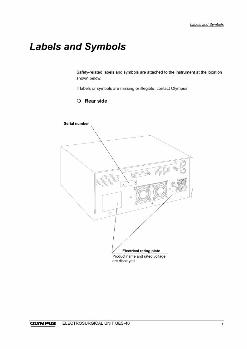
Safety-related labels and symbols are attached to the instrument at the location
shown below.
If labels or symbols are missing or illegible, contact Olympus.
Rear side
Serial number
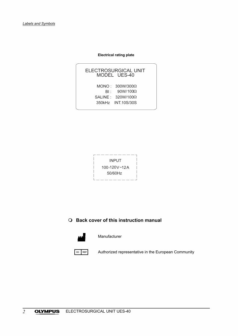
Electrical rating plate
Product name and rated voltage are displayed.
1ELECTROSURGICAL UNIT UES-40
Labels and Symbols
Back cover of this instruction manual
Manufacturer
Authorized representative in the European Community
Electrical rating plate
2 ELECTROSURGICAL UNIT UES-40
Important Information — Please Read Before Use
Important Information — Please Read Before Use
Intended use
This instrument has been designed for use in a medical facility under the
supervision of a trained physician. It has been designed for general (open) and
endoscopic surgery including urology, gynecology, respiratory and
gastroenterology in conjunction with Olympus designed electrosurgical
accessories, endoscopes (fiberscopes, videoscopes and rigid scopes)
applicable for electrosurgery (cutting and coagulation), light sources and other
ancillary equipment.
Do not use this instrument for any purpose other than its intended use.
Instruction manual
This instruction manual contains essential information on using this instrument
safely and effectively. Before use, thoroughly review this manual and the
manuals of all equipment which will be used during the procedure and use the
equipment as instructed.
Keep this and all related instruction manuals in a safe, accessible location.
If you have any questions or comments about any information in this manual,
please contact Olympus.
Terms used in this manual
Wall mains outlet
An electrical outlet that has a terminal used exclusively for grounding.
User qualifications
The operator of this instrument must be a physician or medical personnel under
the supervision of a physician and must have received sufficient training in
electrosurgical procedures. This manual, therefore, does not explain or discuss
endoscopic or electrosurgical procedures.
3ELECTROSURGICAL UNIT UES-40
Important Information — Please Read Before Use
Instrument compatibility
Refer to the “System chart” in the Appendix to confirm that this instrument is
compatible with the ancillary equipment being used.
Using incompatible equipment can result in patient injury and/or equipment
damage.
This instrument complies with the EMC standard for medical electrical
equipment; edition 2 (IEC 60601-1-2: 2001). However, when connecting to an
instrument that complies with the EMC standard for medical electrical
equipment; edition 1 (IEC 60601-1-2: 1993), the whole system complies with
edition 1.
Repair and modification
This instrument does not contain any user-serviceable parts. Do not
disassemble, modify, or attempt to repair it; patient or user injury and/or
equipment damage can result.
Some problems that appear to be malfunctions may be correctable by referring
to Chapter 7, “Troubleshooting”.
If the problem cannot be resolved using the information in Chapter 7, contact
Olympus.
Signal words
The following signal words are used throughout this manual:
Indicates an imminently hazardous situation which, if not
avoided, will result in death or serious injury.
Indicates a potentially hazardous situation which, if not
avoided, could result in death or serious injury.
Indicates a potentially hazardous situation which, if not
avoided, may result in minor or moderate injury. It may also
be used to alert against unsafe practices or potential
equipment damage.
Indicates additional helpful information.
4 ELECTROSURGICAL UNIT UES-40
Important Information — Please Read Before Use
Dangers, warnings and cautions
Follow the dangers, warning and cautions given below when handling this
instrument. This information is to be supplemented by the dangers, warnings
and cautions given in each chapter.
• The high-frequency (HF) equipment, when applied to a
patient with a pacemaker implanted, may cause malfunction
or failure of the pacemaker, seriously affecting the patient.
Before proceeding, confirm with a cardiologist and the
manufacturer of the pacemaker that it is safe to do so.
• To prevent shock hazards, never apply the UES-40 to the
heart in combination with type B or type BF applied part.
• When using the UES-40 on or in the vicinity of the heart, be
sure to use it with the minimum necessary output. Spark
discharge during operation may affect the heart.
• The UES-40 is not explosion-proof construction. Never install
or operate it where flammable gases are present.
• Never install or operate the UES-40 where:
the concentration of oxygen is high.
oxidizing agents (such as nitrous oxide [N2O]) are present
in the atmosphere.
flammable anesthetics and/or gases are present in the
atmosphere.
• If absorbent cotton or gauze is used during the procedure, it
can be ignited by a spark generated in the normal operation
of the equipment.
• Prepare a spare UES-40 as a backup to ensure that the
procedure can be completed without complication in case of
a malfunction. If therapy is possible using non-electrosurgical
equipment, it is also acceptable to prepare such equipment
as a backup.
• Always have a defibrillator ready in case of a cardiac
emergency. During operation of the defibrillator, remove the
endoscope from the patient.
• Never attach the patient plate in the vicinity of a metal
implant. The tissue in the vicinity of the metal implant may be
burned.
5ELECTROSURGICAL UNIT UES-40
Important Information — Please Read Before Use
• Be sure that this instrument is not used adjacent to or
stacked with other equipment (other than the components of
this instrument or system) to avoid electromagnetic
interference.
• Electromagnetic may occur to this instrument near
equipment marked with the following symbol or other
portable and mobile RF communications equipment such as
cellular phones. If radio interference occurs, mitigation
measures may be necessary, such as reorienting or
relocating this instrument or shielding the location.
• Keep the UES-40 and ancillary cords (A cord, bipolar cord,
patient plate cord, hand piece cord) as far away as possible
from other electromedical equipment and cords. If placed too
close, high-frequency signals or spark discharge noise from
the UES-40 may interfere with the operation of other
equipment.
• To prevent patient burns, the UES-40 and ancillary cords (A
cord, bipolar cord, patient plate cord, hand piece cord) should
not come in contact with the patient or metal parts of the
operating table. Furthermore, the patient should also be kept
away from metallic parts of the operating table or other
devices.
• Never loop the cords (A cord, bipolar cord, patient plate cord,
hand piece cord) or bundle cords together with cords
belonging to other medical equipment. The high-frequency
signals or spark discharge noise generated by the UES-40
may interfere with the operation of other medical equipment.
• Do not apply excessive bending, straining, or squeezing
force to any cords. It may cause malfunction.
• Always use the UES-40 as outlined in this instruction manual.
Improper use will not only impede functions and prevent
optimum performance, but may cause equipment damage
and/or complications. Before each use, always inspect the
equipment as outlined in this instruction manual.
• The UES-40 may interfere with electromedical equipment
used in conjunction with it. Before use, thoroughly confirm
the compatibility of all equipment.
6 ELECTROSURGICAL UNIT UES-40
Important Information — Please Read Before Use
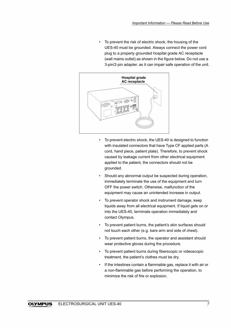
• To prevent the risk of electric shock, the housing of the
UES-40 must be grounded. Always connect the power cord
plug to a properly grounded hospital grade AC receptacle
(wall mains outlet) as shown in the figure below. Do not use a
3-pin/2-pin adapter, as it can impair safe operation of the unit.
• To prevent electric shock, the UES-40 is designed to function
with insulated connectors that have Type CF applied parts (A
cord, hand piece, patient plate). Therefore, to prevent shock
caused by leakage current from other electrical equipment
applied to the patient, the connectors should not be
grounded.
• Should any abnormal output be suspected during operation,
immediately terminate the use of the equipment and turn
OFF the power switch. Otherwise, malfunction of the
equipment may cause an unintended increase in output.
• To prevent operator shock and instrument damage, keep
liquids away from all electrical equipment. If liquid gets on or
into the UES-40, terminate operation immediately and
contact Olympus.
• To prevent patient burns, the patient’s skin surfaces should
not touch each other (e.g. bare arm and side of chest).
• To prevent patient burns, the operator and assistant should
wear protective gloves during the procedure.
• To prevent patient burns during fiberscopic or videoscopic
treatment, the patient’s clothes must be dry.
• If the intestines contain a flammable gas, replace it with air or
a non-flammable gas before performing the operation, to
minimize the risk of fire or explosion.
Hospital grade AC receptacle
7ELECTROSURGICAL UNIT UES-40
Important Information — Please Read Before Use
• During fiberscopic or videoscopic treatment, be sure that the
distal end of the endoscope and metallic parts of the
accessory do not touch the normal tissue surrounding the
target tissue as this may cause severe burns.
• During fiberscopic or videoscopic treatment, be sure that the
distal end of the endoscope or accessory does not contact
bridging fluids surrounding the target tissue. Electric current
may flow to the surrounding normal tissue via the fluids and
cause burns.
• During fiberscopic or videoscopic treatment, never grasp the
target tissue with non-insulated grasping forceps.
Non-insulated grasping forceps will disperse the electric
current and normal operation may be impeded.
• To ensure electrical safety, the UES-40 should not be used in
conjunction with:
Electrical equipment whose safety against leakage
current is not guaranteed.
Electrosurgical equipment whose safety in combined use
is not guaranteed.
• The UES-40 should only be used under the conditions
described in , “Operating environment” in the Appendix. Use
under other conditions may impede normal performance
and/or result in equipment damage.
• If the UES-40 is used in conjunction with a non-Olympus
electrosurgical unit, keep the electrosurgical accessory away
from the target area while the UES-40 is in operation. Do not
activate output of both units simultaneously. Patient or
operator injury may occur due to the concentration of electric
current.
• When using an electrocardiograph or other physiological
monitoring equipment simultaneously with the UES-40 on a
patient, any monitoring electrodes should be placed as far
away as possible from the electrodes (accessories/hand
piece and patient plate) used with the UES-40. If placed too
close, high-frequency signals or spark discharge noise from
the UES-40 may interfere with the operation of an
electrocardiograph or other physiological monitoring
equipment. Needle monitoring electrodes should not be
used, as they may cause patient burns. Physiological
monitoring equipment incorporating high-frequency current
limiting devices is recommended.
8 ELECTROSURGICAL UNIT UES-40
Important Information — Please Read Before Use
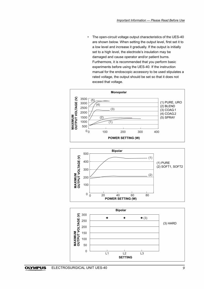
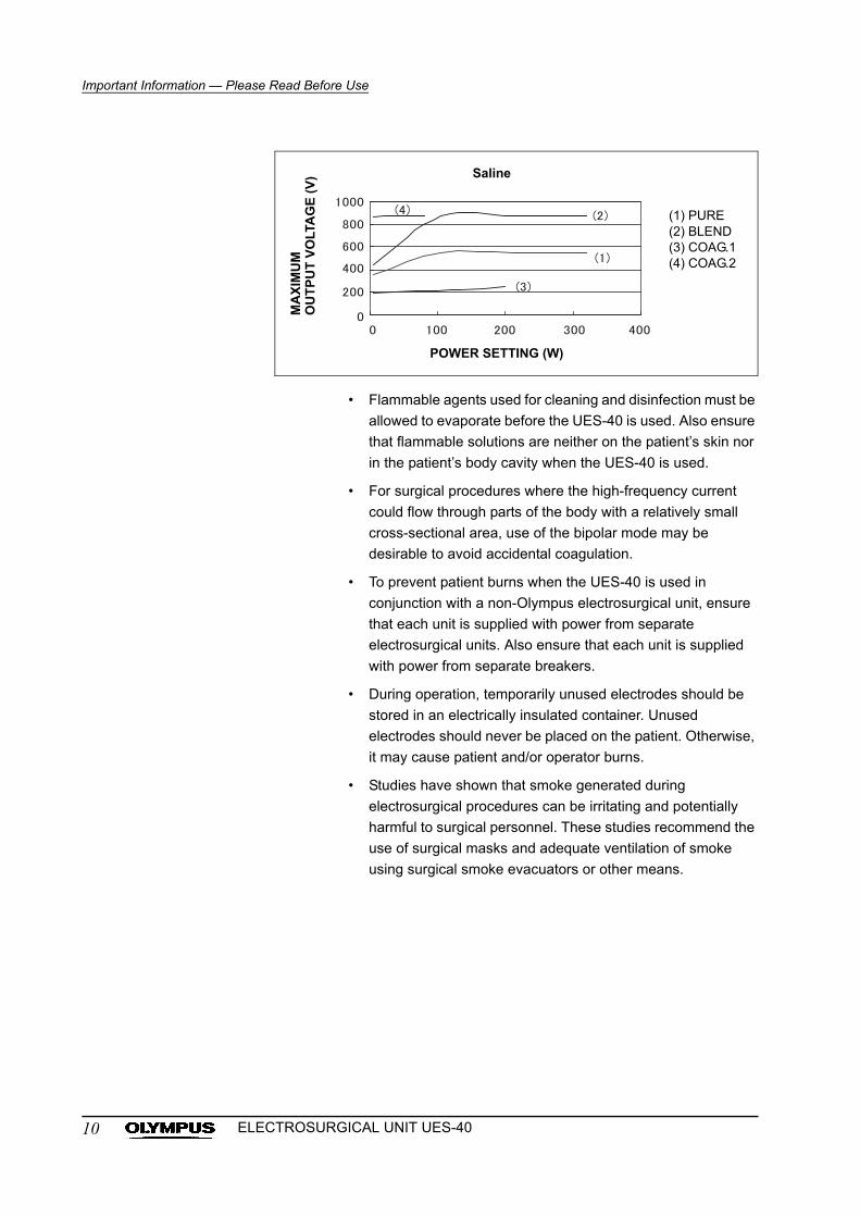
• The open-circuit voltage output characteristics of the UES-40
are shown below. When setting the output level, first set it to
a low level and increase it gradually. If the output is initially
set to a high level, the electrode’s insulation may be
damaged and cause operator and/or patient burns.
Furthermore, it is recommended that you perform basic
experiments before using the UES-40. If the instruction
manual for the endoscopic accessory to be used stipulates a
rated voltage, the output should be set so that it does not
exceed that voltage.
(1) PURE, URO(2) BLEND(3) COAG.1(4) COAG.2(5) SPRAY
Monopolar
MA
XIM
UM
OU
TP
UT
VO
LTA
GE
(V
)
POWER SETTING (W)
(1) PURE(2) SOFT1, SOFT2
Bipolar
MA
XIM
UM
OU
TP
UT
VO
LTA
GE
(V
)
POWER SETTING (W)
(3) HARD
Bipolar
MA
XIM
UM
OU
TP
UT
VO
LTA
GE
(V
)
SETTING
9ELECTROSURGICAL UNIT UES-40
Important Information — Please Read Before Use
• Flammable agents used for cleaning and disinfection must be
allowed to evaporate before the UES-40 is used. Also ensure
that flammable solutions are neither on the patient’s skin nor
in the patient’s body cavity when the UES-40 is used.
• For surgical procedures where the high-frequency current
could flow through parts of the body with a relatively small
cross-sectional area, use of the bipolar mode may be
desirable to avoid accidental coagulation.
• To prevent patient burns when the UES-40 is used in
conjunction with a non-Olympus electrosurgical unit, ensure
that each unit is supplied with power from separate
electrosurgical units. Also ensure that each unit is supplied
with power from separate breakers.
• During operation, temporarily unused electrodes should be
stored in an electrically insulated container. Unused
electrodes should never be placed on the patient. Otherwise,
it may cause patient and/or operator burns.
• Studies have shown that smoke generated during
electrosurgical procedures can be irritating and potentially
harmful to surgical personnel. These studies recommend the
use of surgical masks and adequate ventilation of smoke
using surgical smoke evacuators or other means.
(1) PURE(2) BLEND(3) COAG.1(4) COAG.2
Saline
MA
XIM
UM
OU
TP
UT
VO
LTA
GE
(V
)
POWER SETTING (W)
10 ELECTROSURGICAL UNIT UES-40
Important Information — Please Read Before Use
William S. Sawchuk, et al., “Infectious Papillomavirus in
the Vapor of Warts Treated With Laser or
Electrocoagulation: Detection and Protection”, Journal of
American Academy of Dermatology, Vol.21, No.1 (July,
1989): 41 – 49.
Yoshifumi Tomita, et al., “Mutagencity of Smoke
Condensates Induced by CO2-Laser Irradiation and
Electrocauterization”, Mutation Research, Vol.89 (1989):
145 – 149.
Evaluation Report No.85 – 126. (National Technical
Information Service, 1985): 1 – 28.
• When the patient is moved after the dispersive electrode has
been attached, confirm that the dispersive electrode is still in
proper contact with the patient. Otherwise, it may cause
patient and/or operator burns.
• This instrument cannot be used with an endoscope equipped
with the S cord connector receptacle.
• If the UES-40 is used with a rigid endoscope and is providing
monopolar output, activation of the UES-40 when not in
contact with target tissue or in a position to deliver energy to
target tissue (fulguration) may cause capacitive coupling.
• Do not use the UES-40 in a location exposed to strong
electromagnetic radiation (microwave or short-wave medical
treatment equipment, MRI, radio or mobile phone
equipment). These can impair operation of the unit.
• Always confirm that the unit is safe to use in the system
configuration that you have arranged. In general, the unit
should be used only with equipment shown in the “System
chart” in the Appendix. Using the unit in a configuration that
includes equipment not shown in the “System chart” may not
only prevent the unit from performing as intended, it can
cause patient or operator injury and/or equipment damage.
When you intend to use the unit in a configuration that
includes equipment other than that shown in the “System
chart”, confirm that the unit functions safely in that system
configuration before proceeding.
• Never bring the electrocautery tip in contact with a metallic
clip, electrosurgical accessory or retractor. Doing so could
cause burns to tissue in the vicinity.
• To prevent instrument damage, never short-circuit electrodes
(accessories, hand piece or patient plate).
• Repairs should be performed only by Olympus.
11ELECTROSURGICAL UNIT UES-40
Chapter 1 Checking the Package Contents
Chapter 1 Checking the Package Contents
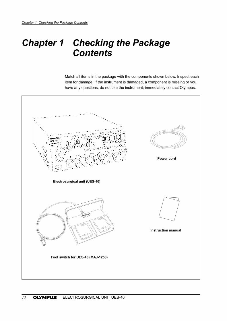
Match all items in the package with the components shown below. Inspect each
item for damage. If the instrument is damaged, a component is missing or you
have any questions, do not use the instrument; immediately contact Olympus.
Power cord
Electrosurgical unit (UES-40)
Instruction manual
Foot switch for UES-40 (MAJ-1258)
12 ELECTROSURGICAL UNIT UES-40
Chapter 1 Checking the Package Contents
The following Olympus items are optional items which may be purchased
separately:
• A cord (A00012A, A00506A, A02915A (MAJ-860), A0335.1, A0336.1,
A0358, A0393)
• Bipolar electrode (A5380, A5382, A5384, A5386, A5388, A5390, A5392,
A5394, O5119)
• Bipolar cord (A00500A, A00504A, A5121.1, A5376, A5377)
• Bipolar foot switch for UES-40 (MAJ-1259)
• A adapter 2 (MAJ-619)
• Interactive cable (MAJ-877)
• Saline cord (WA00013A)
• Patient plate (MAJ-897)
• P cord (MAJ-814)
The following recommended non-Olympus items may also be purchased
separately:
• Hand piece (for connection method, refer to Section 3.6, “Connection of
the hand piece (for monopolar treatment)”)
• The patient plate (for compatible patient plates, refer to Section 3.5,
“Connection of the patient plate (for monopolar treatment)”)
• The bipolar electrode (for compatible bipolar electrodes, refer to Section
3.9, “Connection of the bipolar electrode and bipolar cord (for bipolar
treatment)”)
• Bipolar cord (for compatible bipolar cords, refer to Section 3.9,
“Connection of the bipolar electrode and bipolar cord (for bipolar
treatment)”)
For other equipment combinations, refer to the “System chart” in the Appendix.
• Place the instruction manual next to the UES-40 or in another
easily accessible place.
• Before using an optional item, thoroughly review and
understand the instruction manual provided with that item.
• Some products may not be available in some regions. Please
contact the nearest Olympus office for details.
• Specifications, design and accessories are subject to change
without any notice or obligation on the part of the
manufacturer.
13ELECTROSURGICAL UNIT UES-40
Chapter 2 Nomenclature and Functions
Chapter 2 Nomenclature and Functions
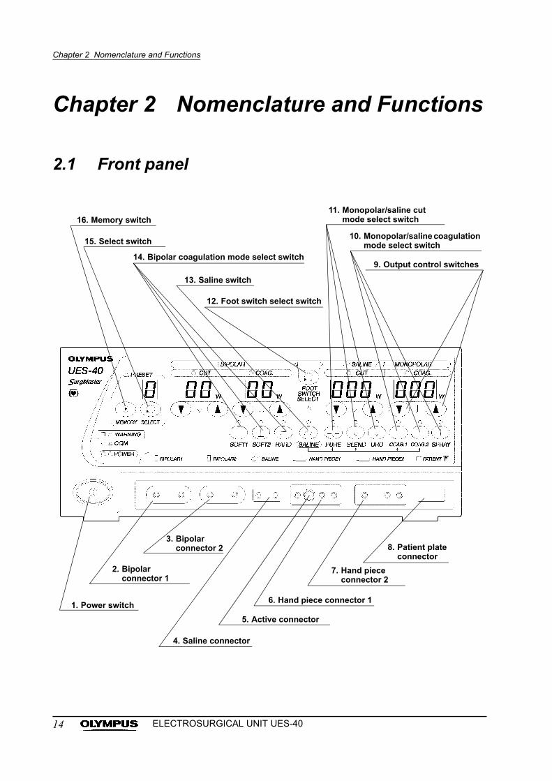
2.1 Front panel
16. Memory switch
15. Select switch
14. Bipolar coagulation mode select switch
13. Saline switch
12. Foot switch select switch
11. Monopolar/saline cut mode select switch
10. Monopolar/saline coagulation mode select switch
9. Output control switches
5. Active connector
4. Saline connector
1. Power switch6. Hand piece connector 1
7. Hand piece connector 2
8. Patient plate connector
3. Bipolar connector 2
2. Bipolar connector 1
14 ELECTROSURGICAL UNIT UES-40
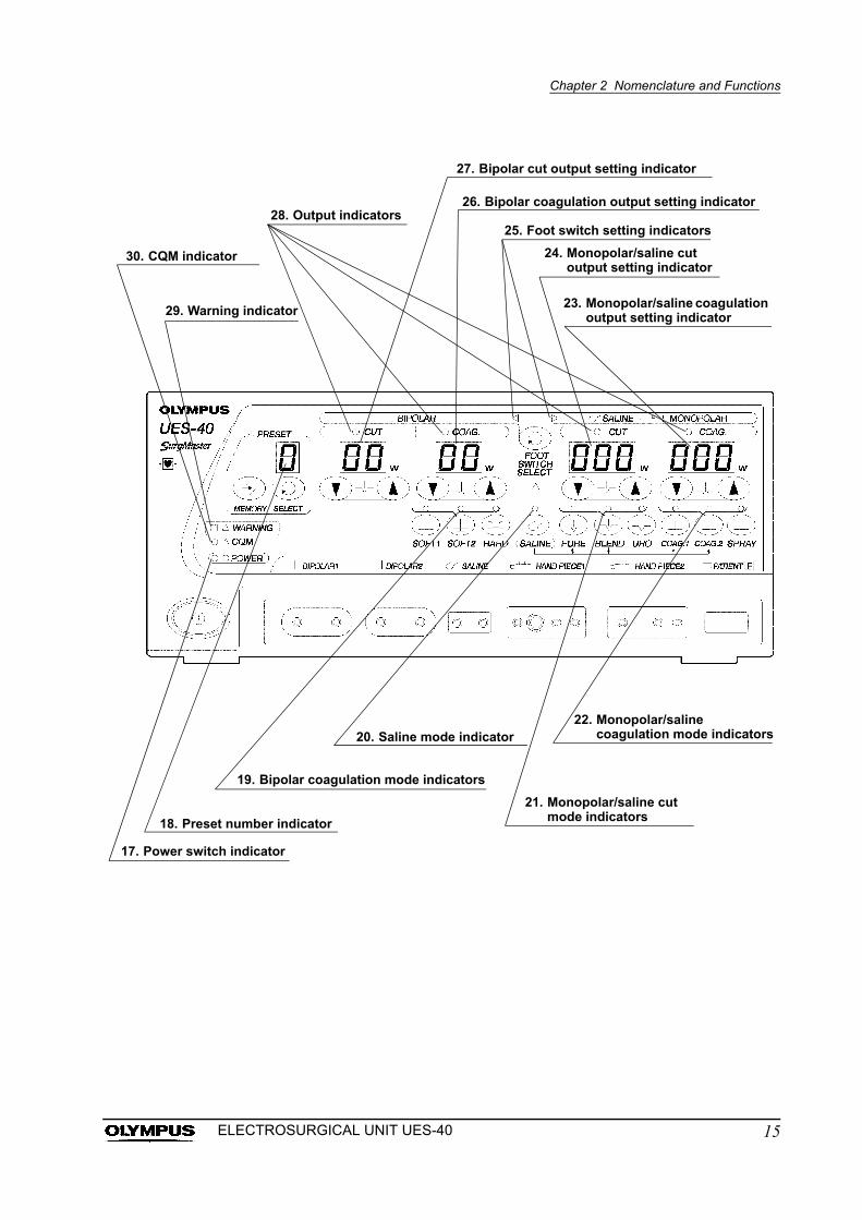
Chapter 2 Nomenclature and Functions
27. Bipolar cut output setting indicator
30. CQM indicator
28. Output indicators
29. Warning indicator
25. Foot switch setting indicators
26. Bipolar coagulation output setting indicator
20. Saline mode indicator
24. Monopolar/saline cut output setting indicator
23. Monopolar/saline coagulation output setting indicator
22. Monopolar/saline coagulation mode indicators
21. Monopolar/saline cut mode indicators
19. Bipolar coagulation mode indicators
18. Preset number indicator
17. Power switch indicator
15ELECTROSURGICAL UNIT UES-40

Chapter 2 Nomenclature and Functions
1. Power switch
Press this switch to turn the power ON. The power switch indicator will
illuminate.
2. Bipolar connector 1
Connect the plug of bipolar electrodes here.
3. Bipolar connector 2
Connect the plug of bipolar electrodes here.
4. Saline connector
Connect the saline cord plug here.
5. Active connector
Connect the plug of the active electrode of the A cord here.
6. Hand piece connector 1
Connect the hand piece plug here.
7. Hand piece connector 2
Connect the hand piece plug here.
8. Patient plate connector
Connect the patient plate plug here.
9. Output control switches
When the “ ” switch is pressed, the value displayed on the output setting
indicator increases. When the “ ” switch is pressed, the value displayed on
the output setting indicator decreases.
10. Monopolar/saline coagulation mode select switch
Press to select the coagulation mode.
11. Monopolar/saline cut mode select switch
Press to select the cut mode.
12. Foot switch select switch
Press to select either the saline/monopolar output or the bipolar output.
13. Saline switch
Press to select the saline mode.
14. Bipolar coagulation mode select switch
Press to select the coagulation mode.
15. Select switch
Press to recall output settings and modes from memory.
16. Memory switch
Press to store the current output settings and modes in memory.
17. Power switch indicator
Lights when the power is ON.
18. Preset number indicator
Displays the number of a memory preset (“1” to “5” or “P”).
16 ELECTROSURGICAL UNIT UES-40
Chapter 2 Nomenclature and Functions
19. Bipolar coagulation mode indicators
Lights when the corresponding coagulation mode select switch is pressed.
20. Saline mode indicator
Lights when the corresponding saline mode switch is pressed.
21. Monopolar/saline cut mode indicators
Lights when the corresponding monopolar/saline cut mode select switch is
pressed.
22. Monopolar/saline coagulation mode indicators
Lights when the corresponding monopolar/saline coagulation mode select
switch is pressed.
23. Monopolar/saline coagulation output setting indicator
Displays the value set with the monopolar/saline output control switches.
24. Monopolar/saline cut output setting indicator
Displays the value set with the monopolar/saline output control switches.
25. Foot switch setting indicators
The lit indicator corresponds to the type of output that can be activated
using the foot switch for the UES-40 (MAJ-1258).
26. Bipolar coagulation output setting indicator
Displays the value set with the bipolar output control switches.
27. Bipolar cut output setting indicator
Displays the value set with the bipolar output control switches.
28. Output indicators
During output, the indicator corresponding to the selected output (cut or
coagulation) is lit.
29. Warning indicator
Lights to indicate a defective device or broken wires in the patient plate.
30. CQM indicator
Lights to indicate that the connection between the patient and the patient
plate is correct when a split-type patient plate is connected.
17ELECTROSURGICAL UNIT UES-40
Chapter 2 Nomenclature and Functions
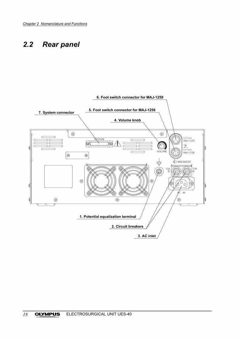
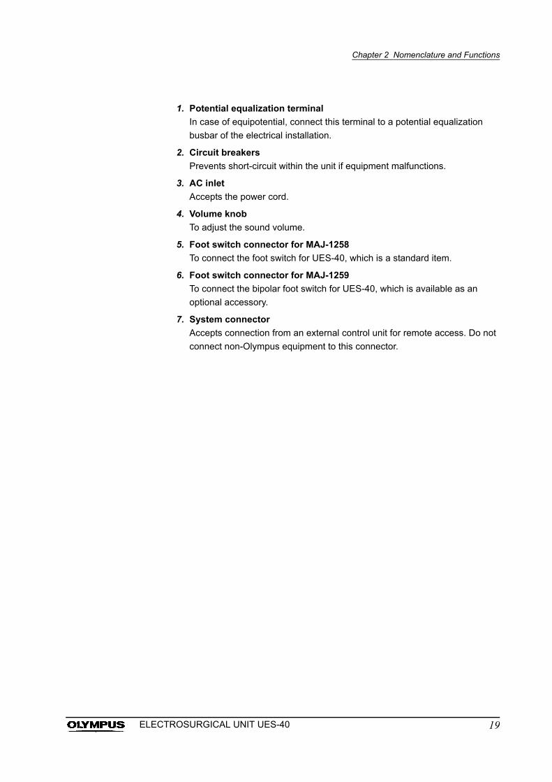
2.2 Rear panel
6. Foot switch connector for MAJ-1259
1. Potential equalization terminal
2. Circuit breakers
5. Foot switch connector for MAJ-1258
4. Volume knob
7. System connector
3. AC inlet
18 ELECTROSURGICAL UNIT UES-40
Chapter 2 Nomenclature and Functions
1. Potential equalization terminal
In case of equipotential, connect this terminal to a potential equalization
busbar of the electrical installation.
2. Circuit breakers
Prevents short-circuit within the unit if equipment malfunctions.
3. AC inlet
Accepts the power cord.
4. Volume knob
To adjust the sound volume.
5. Foot switch connector for MAJ-1258
To connect the foot switch for UES-40, which is a standard item.
6. Foot switch connector for MAJ-1259
To connect the bipolar foot switch for UES-40, which is available as an
optional accessory.
7. System connector
Accepts connection from an external control unit for remote access. Do not
connect non-Olympus equipment to this connector.
19ELECTROSURGICAL UNIT UES-40
Chapter 2 Nomenclature and Functions
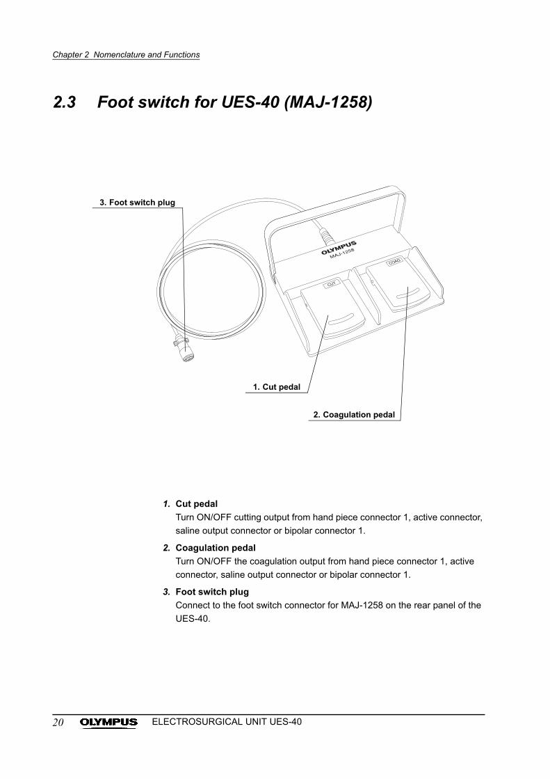
2.3 Foot switch for UES-40 (MAJ-1258)
1. Cut pedal
Turn ON/OFF cutting output from hand piece connector 1, active connector,
saline output connector or bipolar connector 1.
2. Coagulation pedal
Turn ON/OFF the coagulation output from hand piece connector 1, active
connector, saline output connector or bipolar connector 1.
3. Foot switch plug
Connect to the foot switch connector for MAJ-1258 on the rear panel of the
UES-40.
3. Foot switch plug
1. Cut pedal
2. Coagulation pedal
20 ELECTROSURGICAL UNIT UES-40
Chapter 2 Nomenclature and Functions
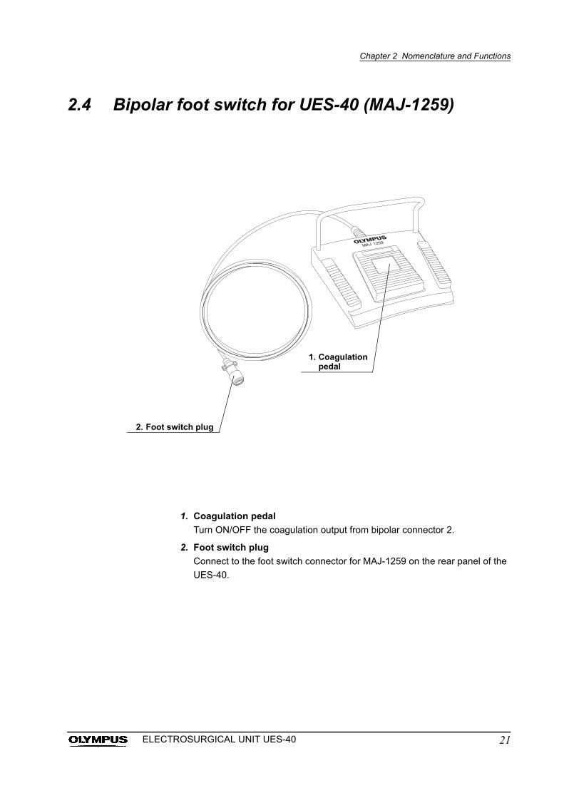
2.4 Bipolar foot switch for UES-40 (MAJ-1259)
1. Coagulation pedal
Turn ON/OFF the coagulation output from bipolar connector 2.
2. Foot switch plug
Connect to the foot switch connector for MAJ-1259 on the rear panel of the
UES-40.
1. Coagulation pedal
2. Foot switch plug
21ELECTROSURGICAL UNIT UES-40
Chapter 2 Nomenclature and Functions
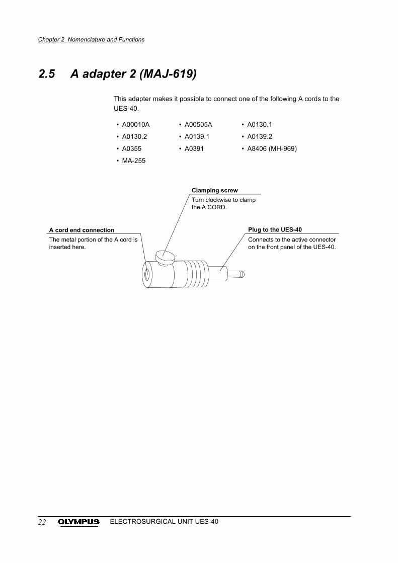
2.5 A adapter 2 (MAJ-619)
This adapter makes it possible to connect one of the following A cords to the
UES-40.
• A00010A • A00505A • A0130.1
• A0130.2 • A0139.1 • A0139.2
• A0355 • A0391 • A8406 (MH-969)
• MA-255
A cord end connection
The metal portion of the A cord is inserted here.
Clamping screw
Turn clockwise to clamp the A CORD.
Plug to the UES-40
Connects to the active connector on the front panel of the UES-40.
22 ELECTROSURGICAL UNIT UES-40
Chapter 3 Installation and Connection
Chapter 3 Installation and Connection
Prepare the instrument and other equipment to be used with this instrument
(shown in the “System chart” in the Appendix) before each use.
Refer to the instruction manuals for each piece of equipment, and install and
connect all equipment as follows:
3.1 Installation of equipment
• Provide adequate ventilation for the rear side of the UES-40,
ensuring that the airflow from the unit’s exhaust fan is
directed away from the patient.
• Ensure that the air vents on the sides of the UES-40 are not
obstructed. Obstructed air vents will result in instrument
damage.
• If the UES-40 is placed on a cart, the cart must be of
adequate strength and size to hold the unit securely.
• Never place the UES-40 on its side or upside down.
Place the instruction manual near the UES-40 or in another
easily accessible place.
1. Thoroughly read and understand the precautions given in “Dangers,
warnings and cautions” and operate the UES-40 accordingly.
2. Place the UES-40 on a level, stable bench or cart.
23ELECTROSURGICAL UNIT UES-40
Chapter 3 Installation and Connection
3.2 Connection to an AC mains power supply
Connect the power plug of the power cord directly to a
grounded wall mains outlet. If the electrosurgical unit is not
grounded properly, it can cause an electric shock and/or fire.
• Firmly plug in the power cord so it will not accidentally be
dislodged during the operation.
• Never apply excessive force to the power cord by bending,
straining, twisting or pressing it.
• Always plug the power cord into a 3-pin outlet. Do not use a
3-pin/2-pin adapter, as it can impair the safe operation of the
unit.
• Do not allow the power cord to become wet. Electric shock,
equipment damage or fire can result.
• Always use the power cord provided with the UES-40. Never
attempt to modify the power cord.
• If the same circuit breaker is used to supply power to other
electrosurgical equipment, carefully consider the power
requirements of the additional equipment and use circuit
breakers that have ample capacity.
• If the voltage of the facility is different from the voltage
indicated on the rating plate of the UES-40, contact Olympus.
• Connect the UES-40 directly to a hospital grade AC
receptacle (wall mains outlet) rather than to a table tap.
1. Confirm that the power is OFF.
2. Connect the power cord to the AC inlet of the UES-40.
3. Connect the power cord plug directly to a hospital grade receptacle (wall
mains outlet) which meets the power requirements indicated on the
electrical rating plate on the rear panel of the UES-40 (see Figure 3.1).
24 ELECTROSURGICAL UNIT UES-40
Chapter 3 Installation and Connection
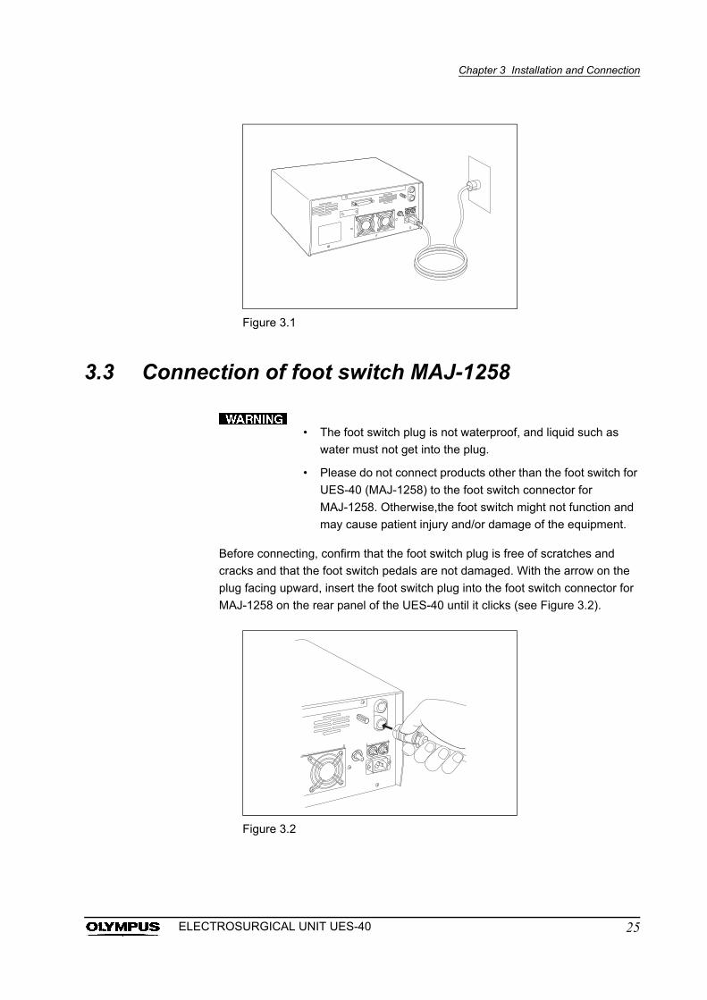
Figure 3.1
3.3 Connection of foot switch MAJ-1258
• The foot switch plug is not waterproof, and liquid such as
water must not get into the plug.
• Please do not connect products other than the foot switch for
UES-40 (MAJ-1258) to the foot switch connector for
MAJ-1258. Otherwise,the foot switch might not function and
may cause patient injury and/or damage of the equipment.
Before connecting, confirm that the foot switch plug is free of scratches and
cracks and that the foot switch pedals are not damaged. With the arrow on the
plug facing upward, insert the foot switch plug into the foot switch connector for
MAJ-1258 on the rear panel of the UES-40 until it clicks (see Figure 3.2).
Figure 3.2
25ELECTROSURGICAL UNIT UES-40
Chapter 3 Installation and Connection
3.4 Connection of foot switch MAJ-1259
• The foot switch plug is not waterproof, and liquid such as
water must not get into the plug.
• Please do not connect products other than the foot switch for
UES-40 (MAJ-1259) to the foot switch connector for
MAJ-1259. Otherwise, the foot switch might not function and
may cause patient injury and/or damage of the equipment.
• When using both monopolar and bipolar, connect bipolar
electrode to connector 2 and control by foot switch
MAJ-1259. Also select “monopolar” by foot switch selection
button on the front panel.
• When using two bipolar electrodes, the electrode connected
to connector 1 can be controlled by the foot switch
MAJ-1258. And the electrode connected to connector 2 can
be controlled by foot switch MAJ-1259.
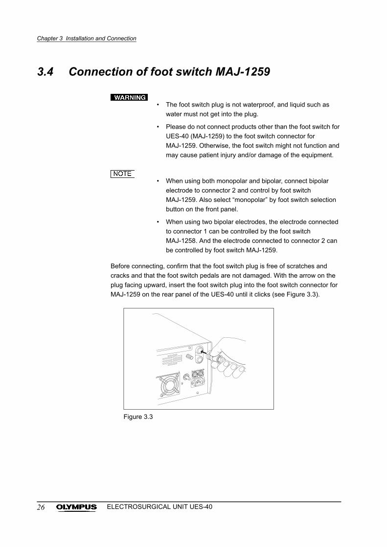
Before connecting, confirm that the foot switch plug is free of scratches and
cracks and that the foot switch pedals are not damaged. With the arrow on the
plug facing upward, insert the foot switch plug into the foot switch connector for
MAJ-1259 on the rear panel of the UES-40 until it clicks (see Figure 3.3).
Figure 3.3
26 ELECTROSURGICAL UNIT UES-40
Chapter 3 Installation and Connection
3.5 Connection of the patient plate (for monopolar treatment)
Improper connection between the patient plate and the patient’s skin surface
may cause burns. Always attach the patient plate as described below:
• Do not use the patient plate if it has been damaged or
modified. This may cause patient burns.
• Never attach the patient plate in the vicinity of a metal
implant. The tissue in the vicinity of the metal implant may get
burned.
• Ensure that the area of the patient’s skin that will come in
contact with the patient plate is completely dry.
• Body hair will impede proper contact with the patient plate. If
necessary, shave all hair from the area to which the patient
plate will be attached.
• Avoid placing the patient plate over bony prominences or
scar tissue as proper contact will not be obtained.
• Do not fold or wrinkle the patient plate. Its entire surface
should be in direct contact with the patient’s skin.
• The patient plate should not be reused.
• Do not attach a patient plate for a bipolar only procedure.
• If the contact between the patient plate and the patient’s skin
is insufficient, the patient warning indicator will light. Set the
power switch to OFF and reattach the patient plate or use a
new plate. Incomplete contact between the patient plate and
the patient’s skin may result in burns.
• If the connection of the patient plate is improper, an alarm will
sound, the warning indicator will light and the output setting
indicator will display an error code when the monopolar
output mode is selected. In this case, turn the power OFF
and reconnect the patient plate.
• For further details on patient plates, refer to their respective
instruction manuals. Please use the following patient plates
when you use the patient plate other than the regular
combination in “System chart” of “Appendix”.
27ELECTROSURGICAL UNIT UES-40
Chapter 3 Installation and Connection
• The connectable patient plates are listed below:
These have been tested and found to be safe. When you
intend to use the unit in a configuration that is not listed in the
“System chart” in the Appendix, confirm that the unit
functions safely in that system configuration before
proceeding. Note that with certain patient plates, the CQM
monitor may malfunction even when the power supply is
normal.
• Do not cut a patient plate to reduce its size. Patient burns due
to high current density may result.
1. After peeling off the protective paper from the patient plate, attach the plate
to the patient’s thigh or place it under the patient’s buttocks.
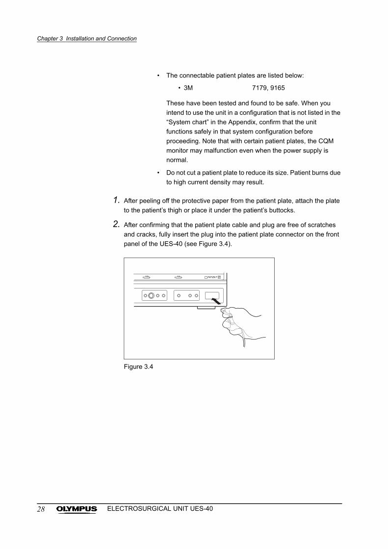
2. After confirming that the patient plate cable and plug are free of scratches
and cracks, fully insert the plug into the patient plate connector on the front
panel of the UES-40 (see Figure 3.4).
Figure 3.4
• 3M 7179, 9165
28 ELECTROSURGICAL UNIT UES-40
Chapter 3 Installation and Connection
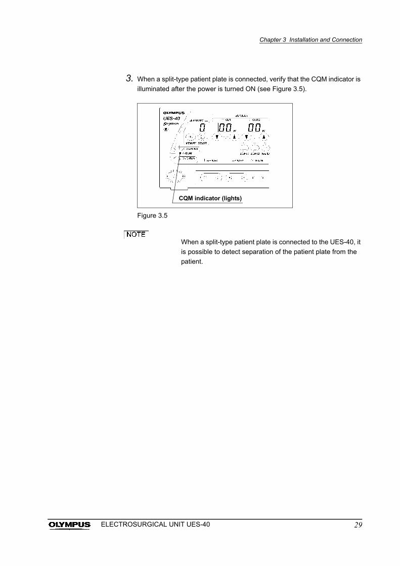
3. When a split-type patient plate is connected, verify that the CQM indicator is
illuminated after the power is turned ON (see Figure 3.5).
Figure 3.5
When a split-type patient plate is connected to the UES-40, it
is possible to detect separation of the patient plate from the
patient.
CQM indicator (lights)
29ELECTROSURGICAL UNIT UES-40
Chapter 3 Installation and Connection
3.6 Connection of the hand piece (for monopolar treatment)
Use a hand piece that complies with IEC 60601-2-2.
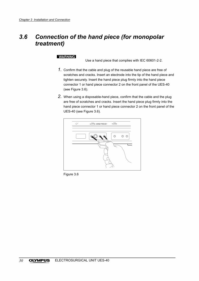
1. Confirm that the cable and plug of the reusable hand piece are free of
scratches and cracks. Insert an electrode into the tip of the hand piece and
tighten securely. Insert the hand piece plug firmly into the hand piece
connector 1 or hand piece connector 2 on the front panel of the UES-40
(see Figure 3.6).
2. When using a disposable-hand piece, confirm that the cable and the plug
are free of scratches and cracks. Insert the hand piece plug firmly into the
hand piece connector 1 or hand piece connector 2 on the front panel of the
UES-40 (see Figure 3.6).
Figure 3.6
30 ELECTROSURGICAL UNIT UES-40
Chapter 3 Installation and Connection
3.7 Connection of the A cord (for monopolar treatment)
Use only Olympus hand instruments for rigid scopes and endo-therapy
accessories for fiberscopes or videoscopes. For further details on the accessory,
refer to its instruction manual. If you have any questions concerning the
compatibility of your accessory, please contact Olympus.
• Wire disconnection in the A cord may result in abnormal
heating, spark generation and decrease in the output level,
which may also lead to unexpected burns, neural stimulation
and/or bleeding. To prevent this, be sure to confirm that the A
cord is not buckled, damaged or bent before use. If the
cutting performance drops or noise is observed in the
endoscopic image during operation, this may be an indication
of wire disconnection of the A cord. In this case, do not use
the A cord; replace it with a new one.
• Connect the A cord securely as described in the following
procedure. Incomplete connection may result in abnormal
heating, spark generation and decrease in the output level,
which may also lead to unexpected burns, neural stimulation
and/or bleeding.
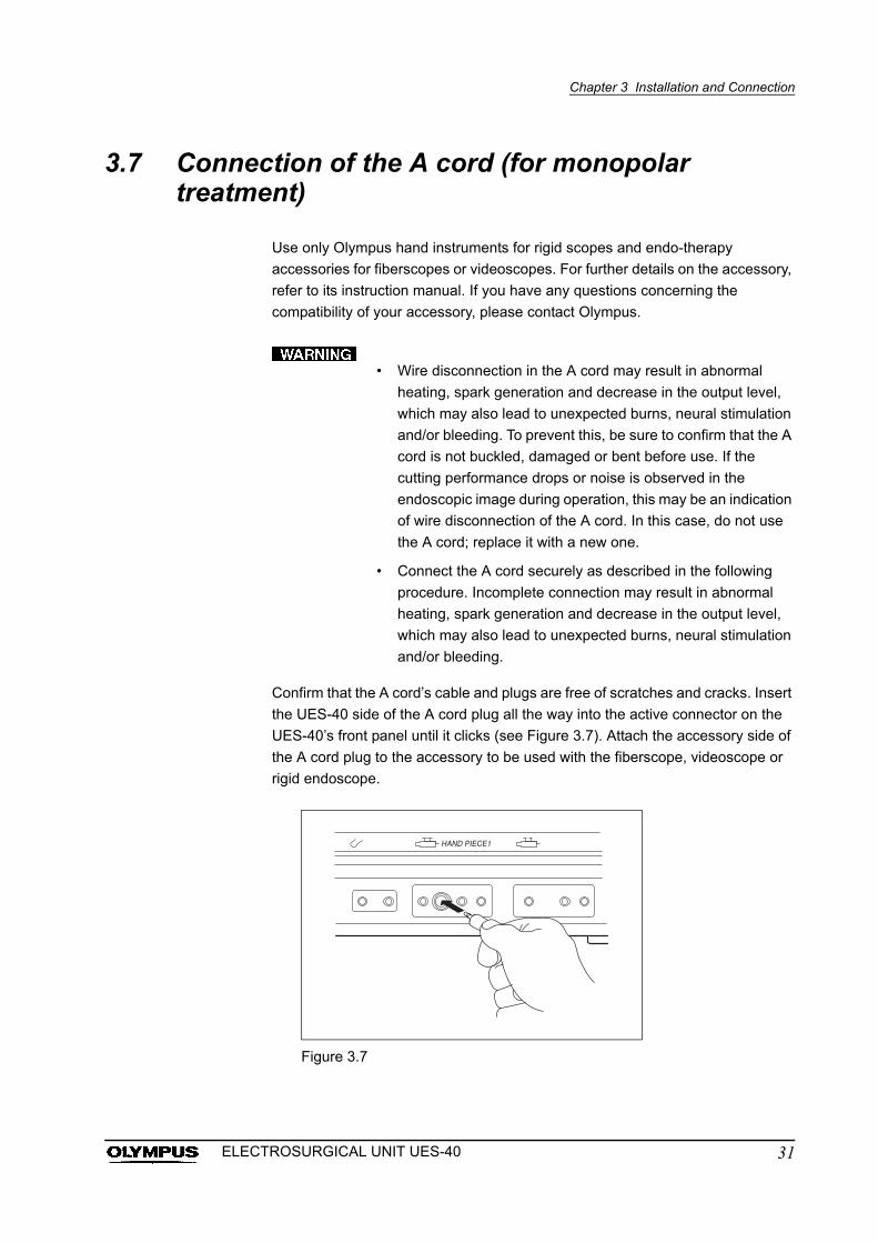
Confirm that the A cord’s cable and plugs are free of scratches and cracks. Insert
the UES-40 side of the A cord plug all the way into the active connector on the
UES-40’s front panel until it clicks (see Figure 3.7). Attach the accessory side of
the A cord plug to the accessory to be used with the fiberscope, videoscope or
rigid endoscope.
Figure 3.7
31ELECTROSURGICAL UNIT UES-40
Chapter 3 Installation and Connection
3.8 Connection of the A adapter 2 (MAJ-619)
Be careful not to drop the A adapter 2. Otherwise, the
clamping screw may be damaged.
The A adapter (MAJ-619) allows the following A cord models
to be connected to the UES-40.
Before use, make sure the instruction manuals of the above mentioned A cord
models are thoroughly reviewed, and closely follow the instructions contained in
these manuals.
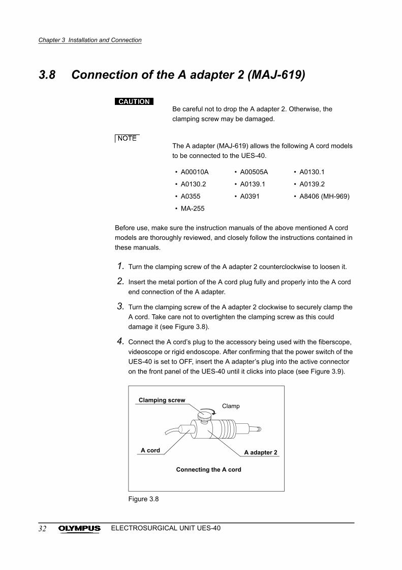
1. Turn the clamping screw of the A adapter 2 counterclockwise to loosen it.
2. Insert the metal portion of the A cord plug fully and properly into the A cord
end connection of the A adapter.
3. Turn the clamping screw of the A adapter 2 clockwise to securely clamp the
A cord. Take care not to overtighten the clamping screw as this could
damage it (see Figure 3.8).
4. Connect the A cord’s plug to the accessory being used with the fiberscope,
videoscope or rigid endoscope. After confirming that the power switch of the
UES-40 is set to OFF, insert the A adapter’s plug into the active connector
on the front panel of the UES-40 until it clicks into place (see Figure 3.9).
Figure 3.8
• A00010A • A00505A • A0130.1
• A0130.2 • A0139.1 • A0139.2
• A0355 • A0391 • A8406 (MH-969)
• MA-255
Clamping screwClamp
A adapter 2A cord
Connecting the A cord
32 ELECTROSURGICAL UNIT UES-40
Chapter 3 Installation and Connection
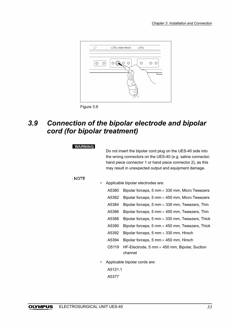
Figure 3.9
3.9 Connection of the bipolar electrode and bipolar cord (for bipolar treatment)
Do not insert the bipolar cord plug on the UES-40 side into
the wrong connectors on the UES-40 (e.g. saline connector,
hand piece connector 1 or hand piece connector 2), as this
may result in unexpected output and equipment damage.
• Applicable bipolar electrodes are:
• Applicable bipolar cords are:
A5380 Bipolar forceps, 5 mm 330 mm, Micro Tweezers
A5382 Bipolar forceps, 5 mm 450 mm, Micro Tweezers
A5384 Bipolar forceps, 5 mm 330 mm, Tweezers, Thin
A5386 Bipolar forceps, 5 mm 450 mm, Tweezers, Thin
A5388 Bipolar forceps, 5 mm 330 mm, Tweezers, Thick
A5390 Bipolar forceps, 5 mm 450 mm, Tweezers, Thick
A5392 Bipolar forceps, 5 mm 330 mm, Hirsch
A5394 Bipolar forceps, 5 mm 450 mm, Hirsch
O5119 HF-Electrode, 5 mm 450 mm, Bipolar, Suction
channel
A5121.1
A5377
33ELECTROSURGICAL UNIT UES-40
Chapter 3 Installation and Connection
• When using both monopolar and bipolar, connect bipolar
electrode to connector 2 and control by foot switch
MAJ-1259. Also select “monopolar” by foot switch selection
button on the front panel.
• When using two bipolar electrodes, the electrode connected
to connector 1 can be controlled by the foot switch
MAJ-1258. And the electrode connected to connector 2 can
be controlled by foot switch MAJ-1259.
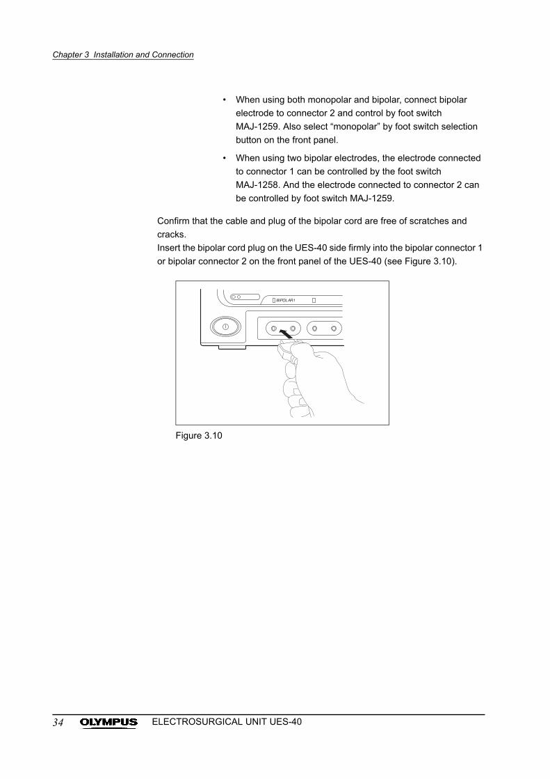
Confirm that the cable and plug of the bipolar cord are free of scratches and
cracks.
Insert the bipolar cord plug on the UES-40 side firmly into the bipolar connector 1
or bipolar connector 2 on the front panel of the UES-40 (see Figure 3.10).
Figure 3.10
34 ELECTROSURGICAL UNIT UES-40
Chapter 3 Installation and Connection
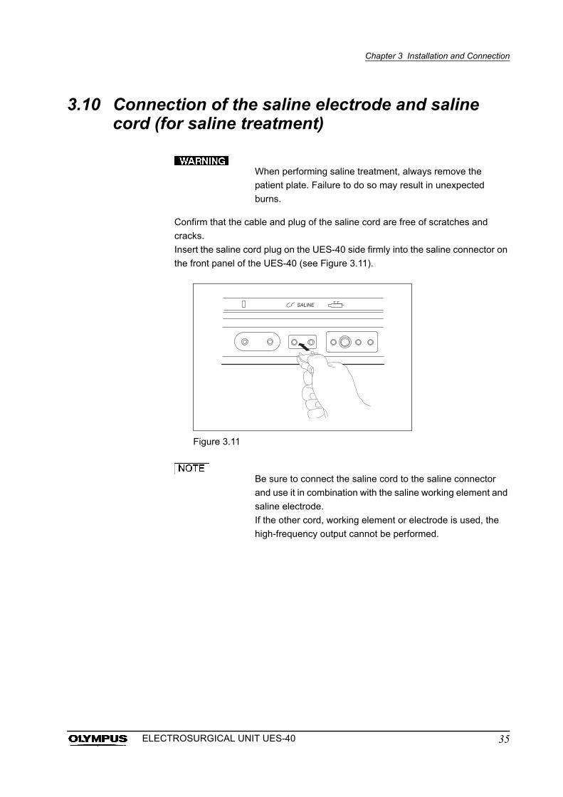
3.10 Connection of the saline electrode and saline cord (for saline treatment)
When performing saline treatment, always remove the
patient plate. Failure to do so may result in unexpected
burns.
Confirm that the cable and plug of the saline cord are free of scratches and
cracks.
Insert the saline cord plug on the UES-40 side firmly into the saline connector on
the front panel of the UES-40 (see Figure 3.11).
Figure 3.11
Be sure to connect the saline cord to the saline connector
and use it in combination with the saline working element and
saline electrode.
If the other cord, working element or electrode is used, the
high-frequency output cannot be performed.
35ELECTROSURGICAL UNIT UES-40
Chapter 4 Inspection
Chapter 4 Inspection
Before each case, inspect this instrument as instructed
below. Inspect other equipment to be used with this
instrument as instructed in their respective instruction
manuals. Should the slightest irregularity be suspected, do
not use the instrument and see Chapter 7, “Troubleshooting”.
If the irregularity is still suspected after consulting Chapter 7,
contact Olympus. Damage or irregularity may compromise
patient or user safety and may result in more severe
equipment damage.
4.1 Inspecting the connections
Prepare this instrument and other equipment to be used with this instrument
(shown in the “System chart” in the Appendix), for the particular case. Refer to
the respective instruction manuals for each item.
Confirm that the connections of the power cord, foot switch, patient plate, A cord,
hand piece, adapter, bipolar electrode, bipolar cord and saline cord are secure
and correct.
36 ELECTROSURGICAL UNIT UES-40
Chapter 4 Inspection
4.2 Inspection of the UES-40
Power supply
When the power is turned ON, confirm that the output tone is
working.
If electrosurgical therapy is started when the output tone is
not working, you may not notice the high-frequency output
and cause unintended burns, bleeding and/or perforation.
If the output tone is not produced, contact Olympus.
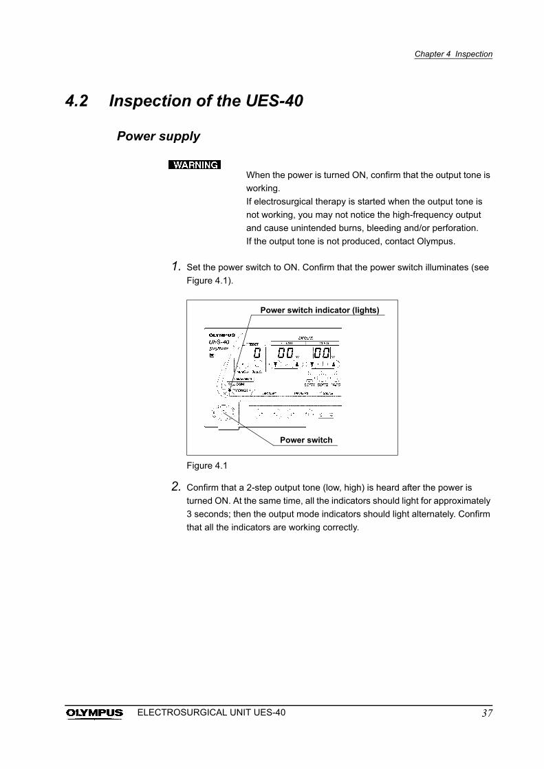
1. Set the power switch to ON. Confirm that the power switch illuminates (see
Figure 4.1).
Figure 4.1
2. Confirm that a 2-step output tone (low, high) is heard after the power is
turned ON. At the same time, all the indicators should light for approximately
3 seconds; then the output mode indicators should light alternately. Confirm
that all the indicators are working correctly.
Power switch indicator (lights)
Power switch
37ELECTROSURGICAL UNIT UES-40
Chapter 4 Inspection
4.3 Inspection of the foot switch operation
If there is a malfunction at the foot switch used in
electrosurgical therapy, continuous output of high-frequency
may cause unintended burns, bleeding and/or perforation of
the patient and/or operator. If the high-frequency is not output
during therapy, the endo-therapy accessory may cut the
tissue mechanically, cause bleeding and/or perforation.
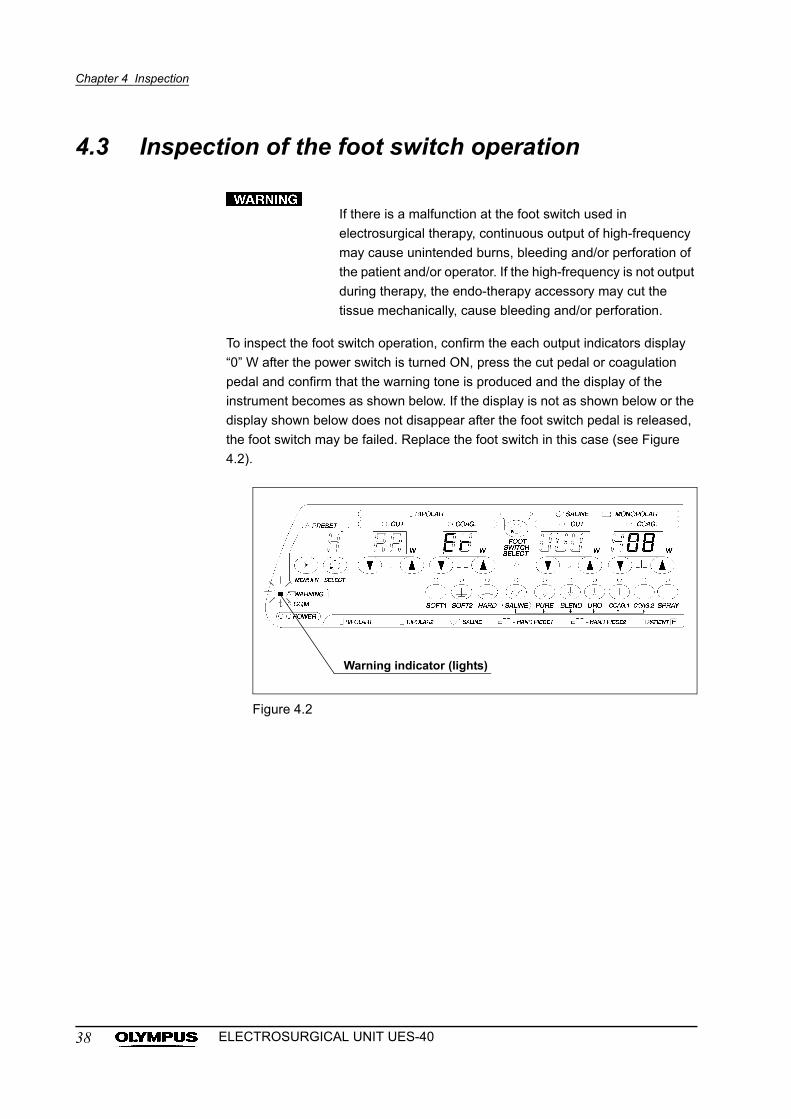
To inspect the foot switch operation, confirm the each output indicators display
“0” W after the power switch is turned ON, press the cut pedal or coagulation
pedal and confirm that the warning tone is produced and the display of the
instrument becomes as shown below. If the display is not as shown below or the
display shown below does not disappear after the foot switch pedal is released,
the foot switch may be failed. Replace the foot switch in this case (see Figure
4.2).
Figure 4.2
Warning indicator (lights)
38 ELECTROSURGICAL UNIT UES-40
Chapter 4 Inspection
4.4 Bipolar setting
1. Press the power switch and confirm that the bipolar “CUT” and “COAG.”
output setting indicators display “0” W.
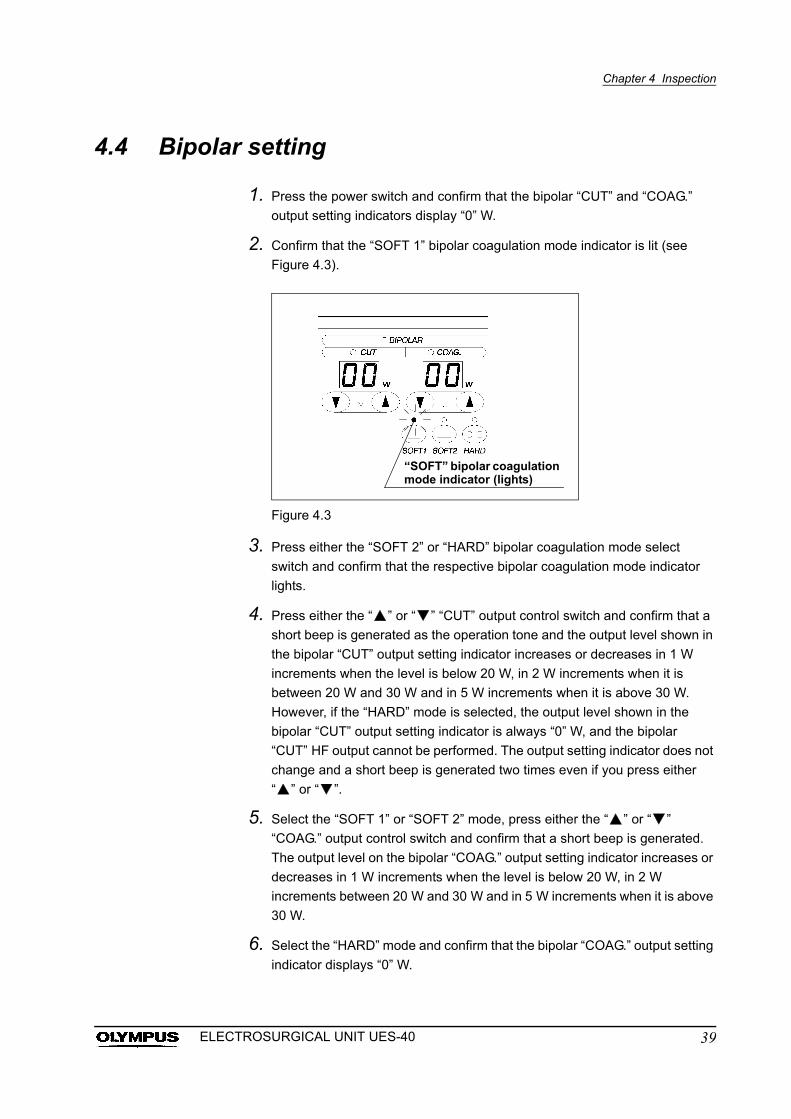
2. Confirm that the “SOFT 1” bipolar coagulation mode indicator is lit (see
Figure 4.3).
Figure 4.3
3. Press either the “SOFT 2” or “HARD” bipolar coagulation mode select
switch and confirm that the respective bipolar coagulation mode indicator
lights.
4. Press either the “ ” or “ ” “CUT” output control switch and confirm that a
short beep is generated as the operation tone and the output level shown in
the bipolar “CUT” output setting indicator increases or decreases in 1 W
increments when the level is below 20 W, in 2 W increments when it is
between 20 W and 30 W and in 5 W increments when it is above 30 W.
However, if the “HARD” mode is selected, the output level shown in the
bipolar “CUT” output setting indicator is always “0” W, and the bipolar
“CUT” HF output cannot be performed. The output setting indicator does not
change and a short beep is generated two times even if you press either
“ ” or “ ”.
5. Select the “SOFT 1” or “SOFT 2” mode, press either the “ ” or “ ”
“COAG.” output control switch and confirm that a short beep is generated.
The output level on the bipolar “COAG.” output setting indicator increases or
decreases in 1 W increments when the level is below 20 W, in 2 W
increments between 20 W and 30 W and in 5 W increments when it is above
30 W.
6. Select the “HARD” mode and confirm that the bipolar “COAG.” output setting
indicator displays “0” W.
“SOFT” bipolar coagulation mode indicator (lights)
39ELECTROSURGICAL UNIT UES-40
Chapter 4 Inspection
7. Select the “HARD” mode, press either the “ ” or “ ” “COAG.” output
control switch and confirm that a short beep is generated. The value on the
bipolar “COAG.” output setting indicator changes between “L1” and “L3”.
By increasing the output level, the time until the output tone changes gets
longer, and the total output energy supplied to the tissue is increased.
• Pressing an output control switch once varies the output
setting by one increment.
Holding an output control switch depressed varies the output
setting continuously.
• When you set the output exceeding the range of the output
setting, the output setting indicator does not change and a
short deep is generated two times even if you press either
“ ” or “ ”.
4.5 Monopolar setting
1. Press the power switch and confirm that the monopolar “CUT” and “COAG.”
output setting indicators display “0” W.
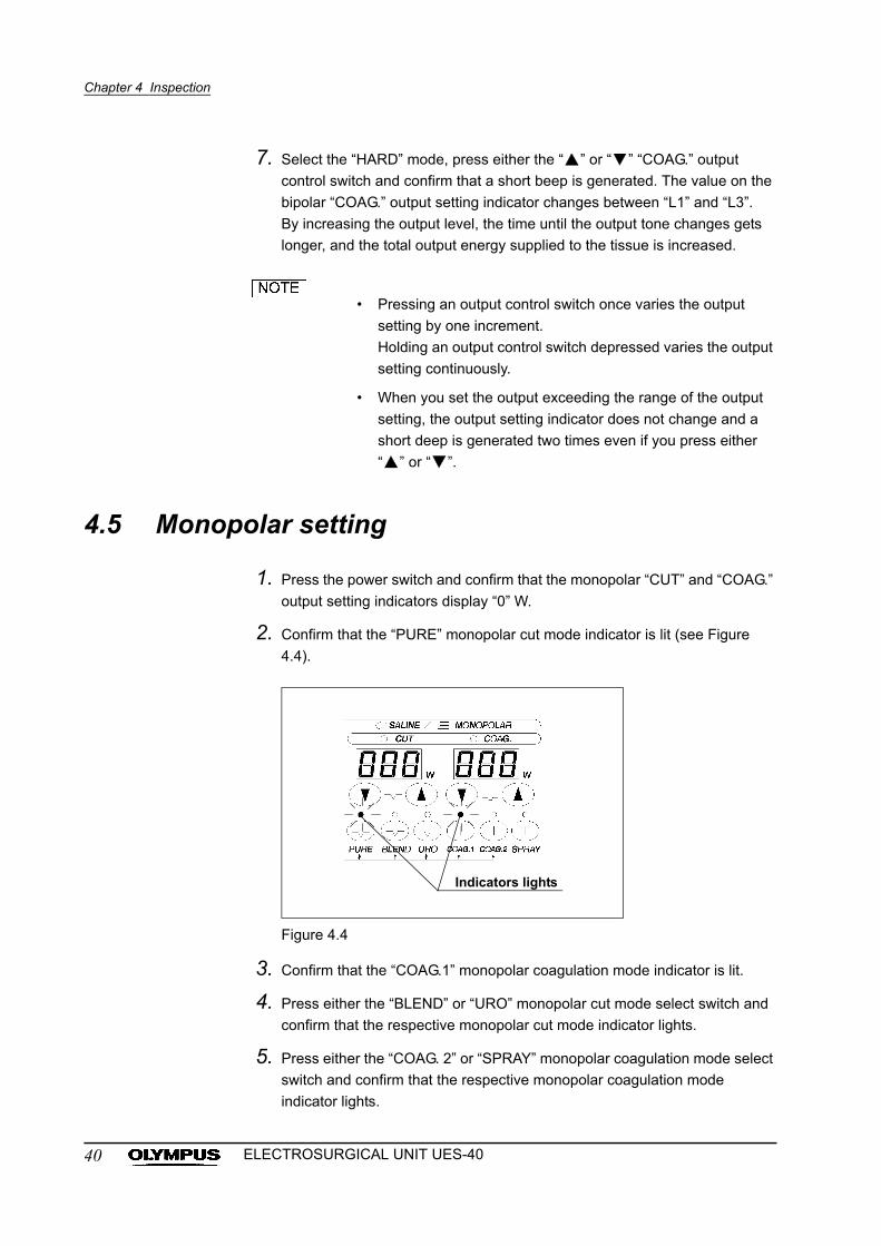
2. Confirm that the “PURE” monopolar cut mode indicator is lit (see Figure
4.4).
Figure 4.4
3. Confirm that the “COAG.1” monopolar coagulation mode indicator is lit.
4. Press either the “BLEND” or “URO” monopolar cut mode select switch and
confirm that the respective monopolar cut mode indicator lights.
5. Press either the “COAG. 2” or “SPRAY” monopolar coagulation mode select
switch and confirm that the respective monopolar coagulation mode
indicator lights.
Indicators lights
40 ELECTROSURGICAL UNIT UES-40
Chapter 4 Inspection
6. Press either the “ ” or “ ” “CUT” output control switch and confirm that a
short beep is generated. The output level on the saline/monopolar “CUT”
output setting indicator increases or decreases in 5 W increments.
7. Press either the “ ” or “ ” “COAG.” output control switch and confirm that
the output level on the saline/monopolar “COAG.” output setting indicator
increases or decreases in 5 W increments, as in Step 6. above.
• Pressing an output control switch once varies the output
setting by one increment.
Holding an output control switch depressed varies the output
setting continuously.
• When you set the output exceeding the range of the output
setting, the output setting indicator does not change and a
short deep is generated two times even if you press either
“ ” or “ ”.
4.6 Saline setting (when saline output mode is used)
• Use an electroconductive physiological saline solution (0.9%
sodium chloride irrigation).
Do not use a nonconductive solution, as this makes it
impossible to obtain the HF output.
• The patient plate is not required for saline output because the
high-frequencies are recovered by the sheath section of the
resectoscope system for saline output. Please use an
Olympus resectoscope system for saline output.
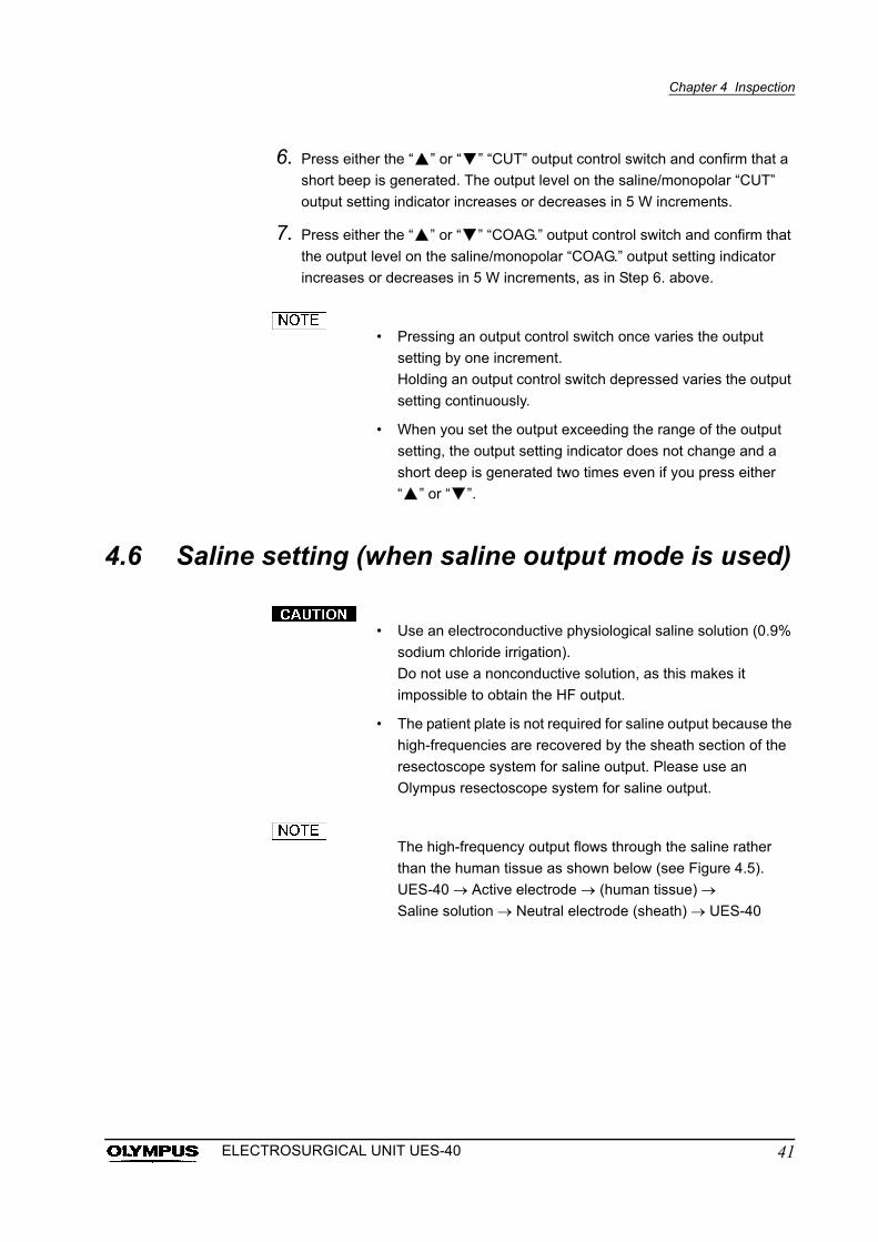
The high-frequency output flows through the saline rather
than the human tissue as shown below (see Figure 4.5).
UES-40 Active electrode (human tissue)
Saline solution Neutral electrode (sheath) UES-40
41ELECTROSURGICAL UNIT UES-40
Chapter 4 Inspection
Figure 4.5
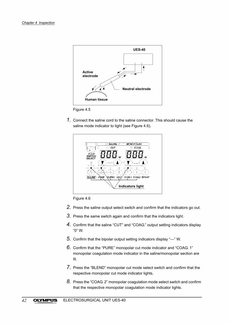
1. Connect the saline cord to the saline connector. This should cause the
saline mode indicator to light (see Figure 4.6).
Figure 4.6
2. Press the saline output select switch and confirm that the indicators go out.
3. Press the same switch again and confirm that the indicators light.
4. Confirm that the saline “CUT” and “COAG.” output setting indicators display
“0” W.
5. Confirm that the bipolar output setting indicators display “—” W.
6. Confirm that the “PURE” monopolar cut mode indicator and “COAG. 1”
monopolar coagulation mode indicator in the saline/monopolar section are
lit.
7. Press the “BLEND” monopolar cut mode select switch and confirm that the
respective monopolar cut mode indicator lights.
8. Press the “COAG. 2” monopolar coagulation mode select switch and confirm
that the respective monopolar coagulation mode indicator lights.
UES-40
Active electrode
Neutral electrode
Human tissue
Indicators light
42 ELECTROSURGICAL UNIT UES-40
Chapter 4 Inspection
9. Press either the “ ” or “ ” “CUT” output control switch and confirm that a
short beep is generated. The output level on the saline/monopolar “CUT”
output setting indicator increases or decreases in 5 W increments.
10. Press either the “ ” or “ ” “COAG.” output control switch and confirm that
the output level on the saline/monopolar “COAG.” output setting indicator
increases or decreases in 5 W increments as in Step 9. above.
• In the saline output mode, it is not possible to use the bipolar
cut and coagulation modes as well as the “URO” monopolar
cut mode and “SPRAY” monopolar coagulation mode.
• The foot switch select switch is disabled in the saline output
mode.
• Pressing an output control switch once varies the output
setting by one increment.
Holding an output control switch depressed varies the output
setting continuously.
• When you set the output exceeding the range of the output
setting, the output setting indicator does not change and a
short deep is generated two times even if you press either
“ ” or “ ”.
43ELECTROSURGICAL UNIT UES-40
Chapter 4 Inspection
4.7 Inspection of warning function
Inspection of patient plate warning
• Be sure to inspect the warning functions before use. If the
warning functions are not normal, the unit’s failure to detect
equipment errors may result in unexpected burns, perforation
and/or bleeding.
• If the foot switch is not working properly, it may be impossible
to start or stop high-frequency output. If output cannot be
stopped, it could result in unexpected burns, bleeding and/or
perforation of the patient.
1. Disconnect the patient plate plug from the patient plate connector on the
front panel of the UES-40.
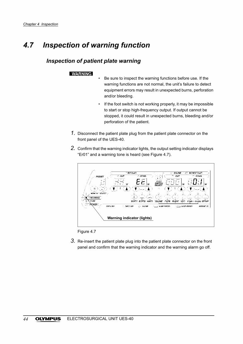
2. Confirm that the warning indicator lights, the output setting indicator displays
“Er01” and a warning tone is heard (see Figure 4.7).
Figure 4.7
3. Re-insert the patient plate plug into the patient plate connector on the front
panel and confirm that the warning indicator and the warning alarm go off.
Warning indicator (lights)
44 ELECTROSURGICAL UNIT UES-40
Chapter 4 Inspection
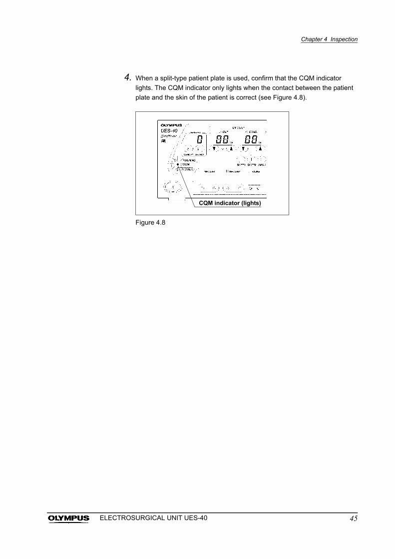
4. When a split-type patient plate is used, confirm that the CQM indicator
lights. The CQM indicator only lights when the contact between the patient
plate and the skin of the patient is correct (see Figure 4.8).
Figure 4.8
CQM indicator (lights)
45ELECTROSURGICAL UNIT UES-40
Chapter 5 Operation
Chapter 5 Operation
The operator of this instrument must be a physician or medical personnel under
the supervision of a physician and must have received sufficient training in
clinical endoscopic technique.
This manual, therefore, does not explain or discuss clinical endoscopic
procedures. It only describes basic operation and precautions related to the
operation of this instrument.
The HF equipment, when applied to a patient with a
pacemaker implanted, may cause malfunctioning or failure of
the pacemaker, seriously affecting the patient. Before
proceeding, confirm with a cardiologist and the manufacturer
of the pacemaker that it is safe to do so.
• Wear personal protective equipment to guard against
dangerous chemicals and potentially infectious material.
During operation, wear appropriate protective equipment,
such as eye wear, face mask, moisture-resistant clothing and
chemical-resistant gloves that fit properly and are long
enough so that your skin is not exposed.
• Laparoscopic surgery presents a risk of gas embolism
because the procedure introduces gas into the abdominal
cavity by the pneumoperitoneum technique. Before
performing the procedure, confirm that the
pneumoperitoneum equipment to be used is working
properly.
• Avoid unintended contact of the electrode tip with patient
tissue when high-frequencies are not output. Otherwise, the
heat of the electrode tip may cause burns.
• Do not activate high-frequency output while the electrode is
in contact with a piece of electroconductive equipment.
Otherwise, unexpected burns may result.
46 ELECTROSURGICAL UNIT UES-40
Chapter 5 Operation
5.1 Turn the power ON
After confirming that the accessories for the procedure have been connected
correctly as described in Chapter 3, “Installation and Connection”, turn the power
ON as described in Chapter 4, “Inspection”.
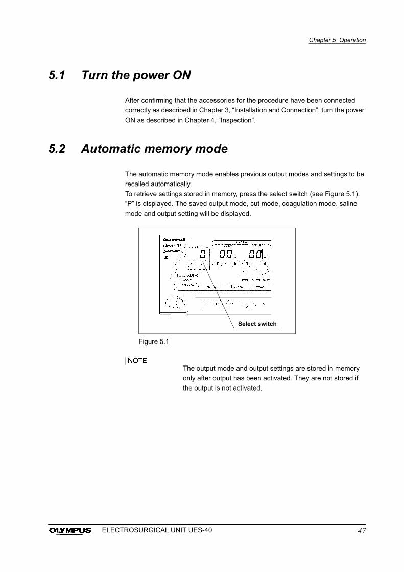
5.2 Automatic memory mode
The automatic memory mode enables previous output modes and settings to be
recalled automatically.
To retrieve settings stored in memory, press the select switch (see Figure 5.1).
“P” is displayed. The saved output mode, cut mode, coagulation mode, saline
mode and output setting will be displayed.
Figure 5.1
The output mode and output settings are stored in memory
only after output has been activated. They are not stored if
the output is not activated.
Select switch
47ELECTROSURGICAL UNIT UES-40
Chapter 5 Operation
5.3 Preset mode
To set the output using the preset mode, it is required to store the output setting
values to be used in advance. Preset each output setting value as described in
the following procedure.
Storing settings in memory
Preset mode is divided into memory areas 1 to 5.
The default initial output settings are 0 W.
1. Turn the power ON.
2. Press the mode select switch and output control switch so that the desired
output setting and output mode are displayed on the output setting indicator.
3. Display the desired output settings and output mode on the indicators and
press the memory switch.
4. Press the select switch and confirm that the preset number indicator cycles
through “1” “2” “3” “4” “5” “1” in this order, and then select the
preset number to be used.
5. Press the memory switch while the preset number indicator is blinking (for
5 seconds).
6. The display of the selected preset number is lit from blinking and the
settings and mode are stored under the selected preset number.
48 ELECTROSURGICAL UNIT UES-40
Chapter 5 Operation
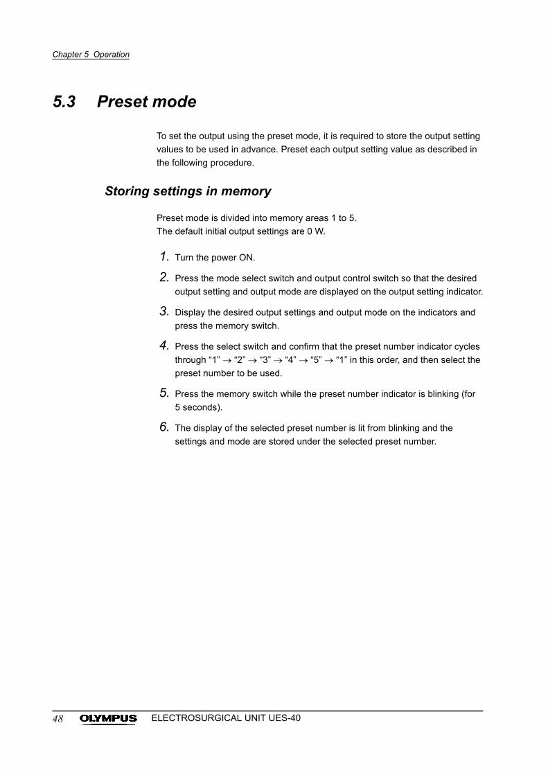
• The settings cannot be stored unless the memory switch is
pressed.
• The settings cannot be stored unless a preset number is
displayed.
• If the memory switch is not pressed while the preset number
is blinking, the setting and mode cannot be stored. If the
preset number disappears, restart the procedure from Step
2.
• To preset another output setting, restart the procedure from
Step 1.
Figure 5.2
Memory switch
Select switch
49ELECTROSURGICAL UNIT UES-40
Chapter 5 Operation
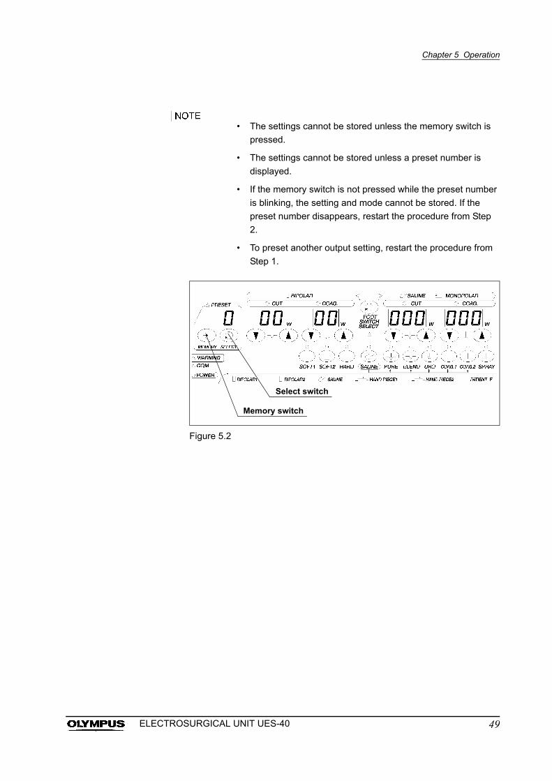
Recalling settings from memory
Settings can be recalled as described below.
1. Turn the power ON.
2. Press the select switch to display the preset number containing the desired
settings.
3. The output setting indicators and the output mode indicators display the
recalled output settings (see Figure 5.3).
Figure 5.3
• When preset settings are recalled while the saline output
selection indicator is not lit, the bipolar and monopolar
settings are displayed together with the current mode
indication.
• To recall preset settings in the saline mode, light up the saline
output selection indicator as described in Section 4.6, “Saline
setting (when saline output mode is used)” on page 41.
The output setting indicators and the output mode indicators display recalled output settings.
50 ELECTROSURGICAL UNIT UES-40
Chapter 5 Operation
Changing settings in memory
Stored settings can be modified as described below.
1. Press the select switch to display the preset number containing the modified
settings.
2. Select the preset number and activate the desired output setting and output
mode.
3. Press the memory switch.
4. Press the select switch, select the preset number in which you want to store
the new settings and mode.
5. Press the memory switch while the preset number indicator is blinking (for
5 seconds).
6. The display of the selected preset number is lit from blinking and the
settings and mode are stored under the selected preset number.
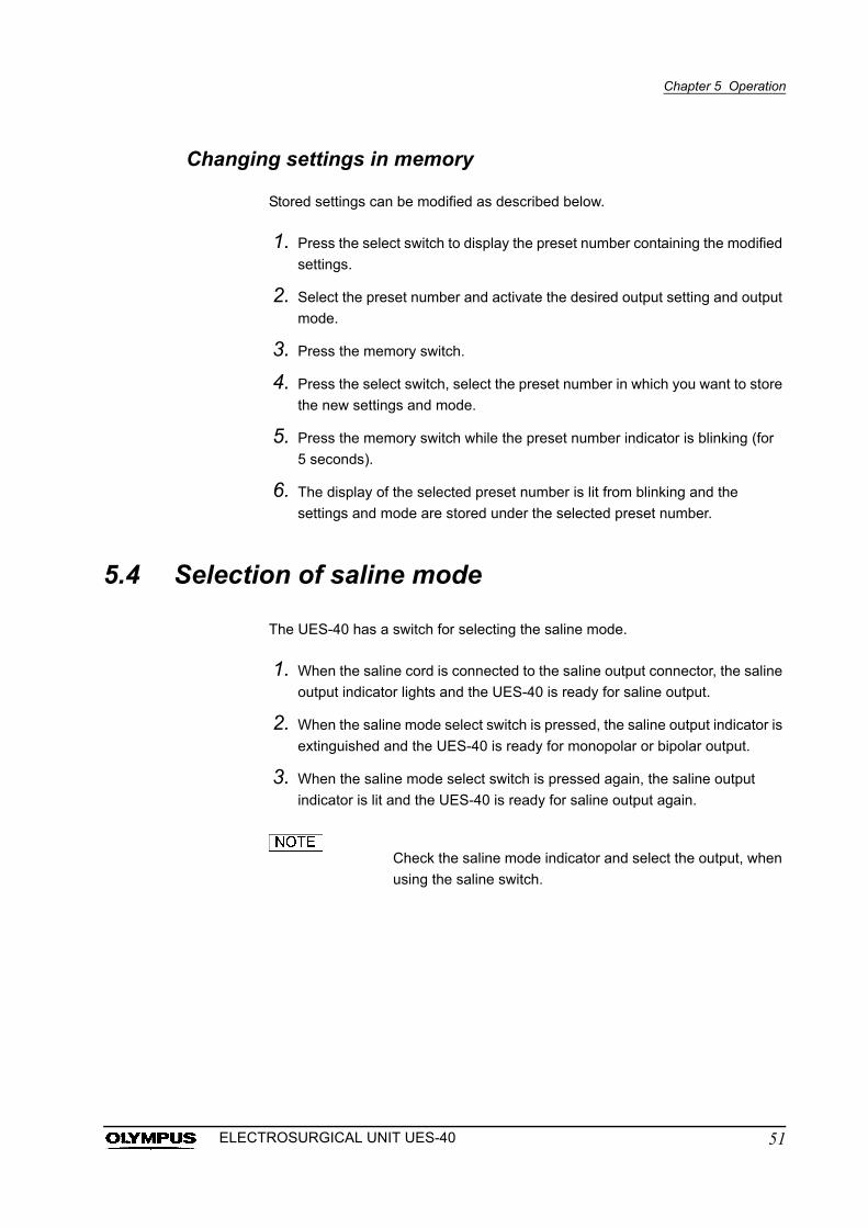
5.4 Selection of saline mode
The UES-40 has a switch for selecting the saline mode.
1. When the saline cord is connected to the saline output connector, the saline
output indicator lights and the UES-40 is ready for saline output.
2. When the saline mode select switch is pressed, the saline output indicator is
extinguished and the UES-40 is ready for monopolar or bipolar output.
3. When the saline mode select switch is pressed again, the saline output
indicator is lit and the UES-40 is ready for saline output again.
Check the saline mode indicator and select the output, when
using the saline switch.
51ELECTROSURGICAL UNIT UES-40
Chapter 5 Operation
5.5 Selection of foot switch output
The UES-40 has a switch for selecting the foot switch output. This feature allows
the foot switch for the UES-40 (MAJ-1258) to supply either monopolar, bipolar or
saline output.
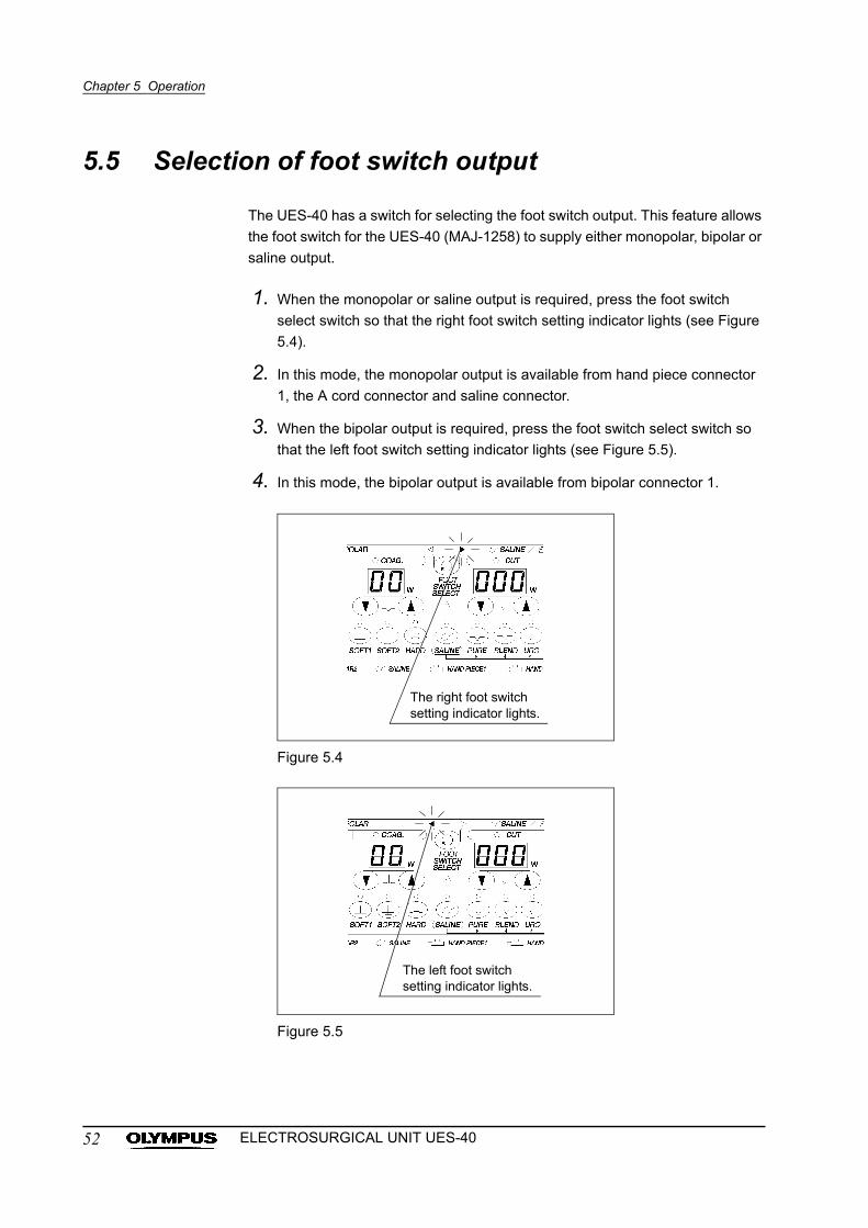
1. When the monopolar or saline output is required, press the foot switch
select switch so that the right foot switch setting indicator lights (see Figure
5.4).
2. In this mode, the monopolar output is available from hand piece connector
1, the A cord connector and saline connector.
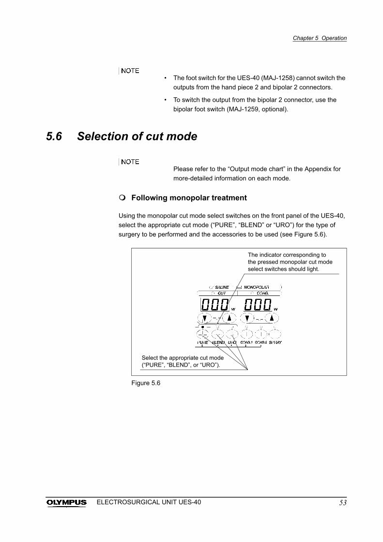
3. When the bipolar output is required, press the foot switch select switch so
that the left foot switch setting indicator lights (see Figure 5.5).
4. In this mode, the bipolar output is available from bipolar connector 1.
Figure 5.4
Figure 5.5
The right foot switch setting indicator lights.
The left foot switch setting indicator lights.
52 ELECTROSURGICAL UNIT UES-40
Chapter 5 Operation
• The foot switch for the UES-40 (MAJ-1258) cannot switch the
outputs from the hand piece 2 and bipolar 2 connectors.
• To switch the output from the bipolar 2 connector, use the
bipolar foot switch (MAJ-1259, optional).
5.6 Selection of cut mode
Please refer to the “Output mode chart” in the Appendix for
more-detailed information on each mode.
Following monopolar treatment
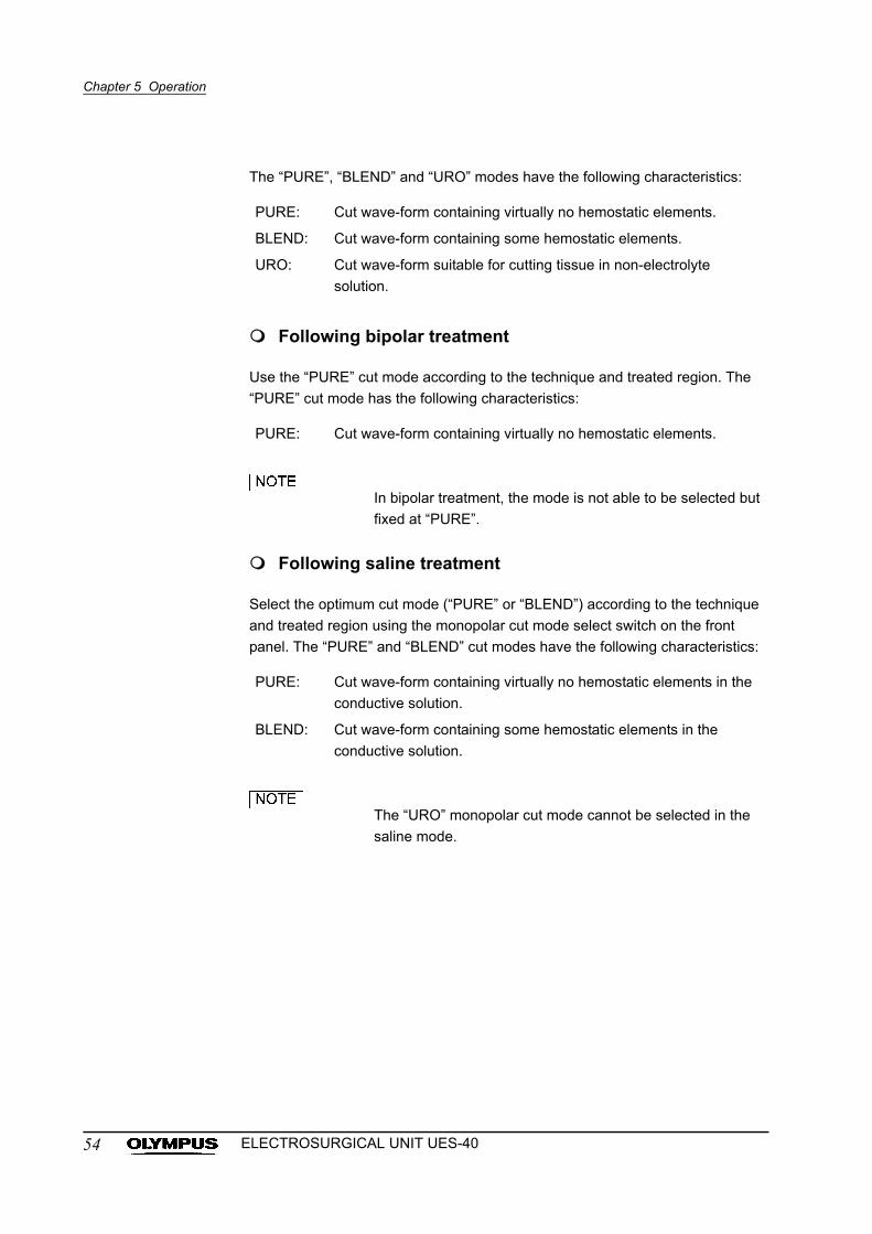
Using the monopolar cut mode select switches on the front panel of the UES-40,
select the appropriate cut mode (“PURE”, “BLEND” or “URO”) for the type of
surgery to be performed and the accessories to be used (see Figure 5.6).
Figure 5.6
The indicator corresponding to the pressed monopolar cut mode select switches should light.
Select the appropriate cut mode (“PURE”, “BLEND”, or “URO”).
53ELECTROSURGICAL UNIT UES-40
Chapter 5 Operation
The “PURE”, “BLEND” and “URO” modes have the following characteristics:
Following bipolar treatment
Use the “PURE” cut mode according to the technique and treated region. The
“PURE” cut mode has the following characteristics:
In bipolar treatment, the mode is not able to be selected but
fixed at “PURE”.
Following saline treatment
Select the optimum cut mode (“PURE” or “BLEND”) according to the technique
and treated region using the monopolar cut mode select switch on the front
panel. The “PURE” and “BLEND” cut modes have the following characteristics:
The “URO” monopolar cut mode cannot be selected in the
saline mode.
PURE: Cut wave-form containing virtually no hemostatic elements.
BLEND: Cut wave-form containing some hemostatic elements.
URO: Cut wave-form suitable for cutting tissue in non-electrolyte
solution.
PURE: Cut wave-form containing virtually no hemostatic elements.
PURE: Cut wave-form containing virtually no hemostatic elements in the
conductive solution.
BLEND: Cut wave-form containing some hemostatic elements in the
conductive solution.
54 ELECTROSURGICAL UNIT UES-40
Chapter 5 Operation
5.7 Selection of coagulation mode
Please refer to the “Output mode chart” in the Appendix for
more-detailed information on each mode.
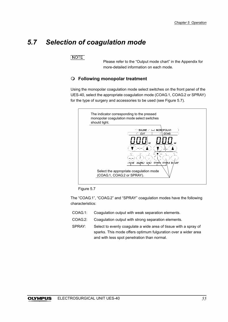
Following monopolar treatment
Using the monopolar coagulation mode select switches on the front panel of the
UES-40, select the appropriate coagulation mode (COAG.1, COAG.2 or SPRAY)
for the type of surgery and accessories to be used (see Figure 5.7).
Figure 5.7
The “COAG.1”, “COAG.2” and “SPRAY” coagulation modes have the following
characteristics:
COAG.1: Coagulation output with weak separation elements.
COAG.2: Coagulation output with strong separation elements.
SPRAY: Select to evenly coagulate a wide area of tissue with a spray of
sparks. This mode offers optimum fulguration over a wider area
and with less spot penetration than normal.
The indicator corresponding to the pressed monopolar coagulation mode select switches should light.
Select the appropriate coagulation mode (COAG.1, COAG.2 or SPRAY).
55ELECTROSURGICAL UNIT UES-40
Chapter 5 Operation
Following bipolar treatment
• Hold the targeted tissue firmly during bipolar treatment. If the
electrodes on the distal end are shorted, it will not be
possible to obtain the intended output level and the bipolar
forceps may be damaged.
• When using tweezers forceps with a small grasping tip, do
not select HARD mode. Doing so could cause spark
discharge from the electrode and burns to tissue.
• Hold the targeted tissue firmly during coagulation output in
the “HARD” mode. If the tissue is not holded firmly, it will
become impossible to obtain the intended output energy and
the tissue may not be coagulate sufficiently.
• When the tissue is sticking to the forceps, do not remove the
tissue by main force from the forceps. If the tissue removed
by main force from forceps, it may result in unintended
damages and/or bleeding.
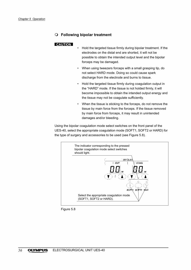
Using the bipolar coagulation mode select switches on the front panel of the
UES-40, select the appropriate coagulation mode (SOFT1, SOFT2 or HARD) for
the type of surgery and accessories to be used (see Figure 5.8).
Figure 5.8
The indicator corresponding to the pressed bipolar coagulation mode select switches should light.
Select the appropriate coagulation mode (SOFT1, SOFT2 or HARD).
56 ELECTROSURGICAL UNIT UES-40
Chapter 5 Operation
The “SOFT1” “SOFT2” and “HARD” coagulation modes have the following
characteristics:
• Always select the SOFT1 coagulation mode to prevent insufficient when
using bipolar cutting scissors and similar instruments.
• Select the SOFT1 or SOFT2 coagulation mode to prevent insufficient
when using bipolar.
• When a change in the tissue status is detected during coagulation
output in the “SOFT2” or “HARD” mode, the output tone changes, and
the output is decreased automatically. The time to change the output
tone depends on the targeted tissue, the operative field, the holding
condition, the output setting and so on.
• The output tone change is a reference to indicate the tissue status
changed. Confirm the tissue status with your own eyes whether the
tissue is coagulated sufficiently.
Following saline treatment
Using the saline coagulation mode select switches on the front panel of the
UES-40, select the appropriate coagulation mode (COAG.1, COAG.2) for the
type of surgery and accessories to be used.
The “COAG.1” “COAG.2” modes have the following characteristics:
The “SPRAY” monopolar coagulation mode cannot be
selected in the saline mode.
SOFT1: Coagulation for desiccating the area of tissue that is pinched
between the two electrodes without burning the tissue.
SOFT2: Coagulation for use in hemostasis with a stronger tissue burn
prevention effect than SOFT1.
HARD: Coagulation featuring repetition of indirect outputs to apply a high
energy output.
COAG.1: Coagulation without spark discharge.
COAG.2: Coagulation with spark discharge.
57ELECTROSURGICAL UNIT UES-40
Chapter 5 Operation
5.8 Setting output
Use the lowest appropriate output level to achieve the
desired effect. Using a higher output level than required may
result in unexpected burns to the patient or operator, or
perforation and/or bleeding of the patient.
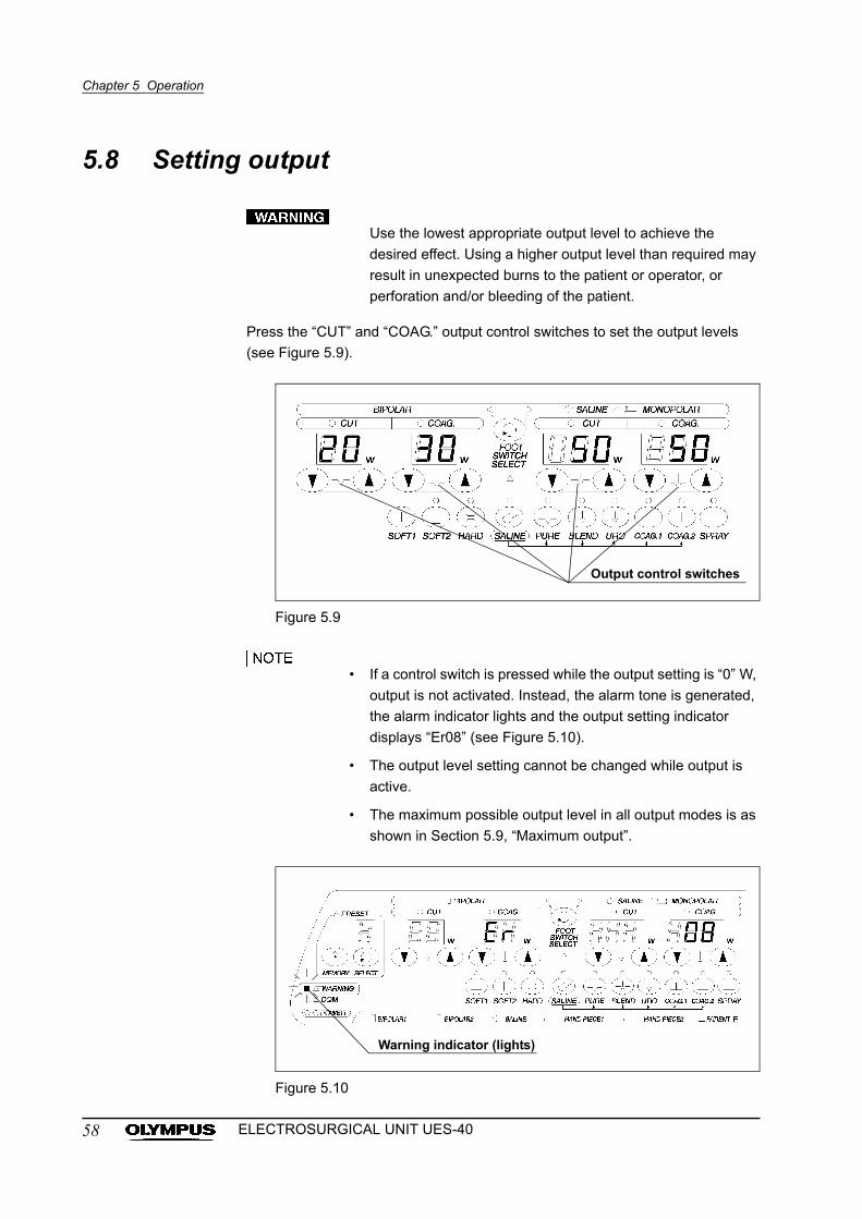
Press the “CUT” and “COAG.” output control switches to set the output levels
(see Figure 5.9).
Figure 5.9
• If a control switch is pressed while the output setting is “0” W,
output is not activated. Instead, the alarm tone is generated,
the alarm indicator lights and the output setting indicator
displays “Er08” (see Figure 5.10).
• The output level setting cannot be changed while output is
active.
• The maximum possible output level in all output modes is as
shown in Section 5.9, “Maximum output”.
Figure 5.10
Output control switches
Warning indicator (lights)
58 ELECTROSURGICAL UNIT UES-40
Chapter 5 Operation
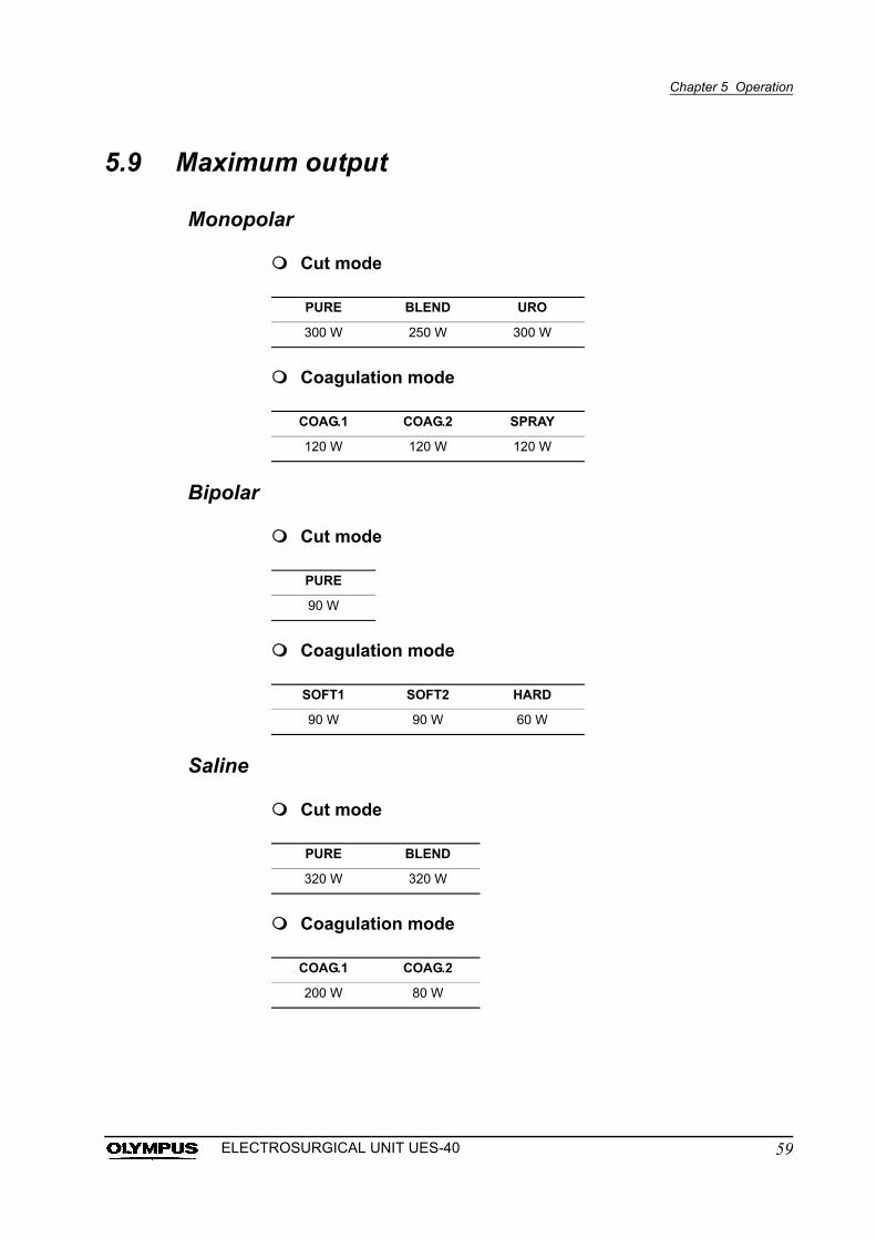
5.9 Maximum output
Monopolar
Cut mode
Coagulation mode
Bipolar
Cut mode
Coagulation mode
Saline
Cut mode
Coagulation mode
PURE BLEND URO
300 W 250 W 300 W
COAG.1 COAG.2 SPRAY
120 W 120 W 120 W
PURE
90 W
SOFT1 SOFT2 HARD
90 W 90 W 60 W
PURE BLEND
320 W 320 W
COAG.1 COAG.2
200 W 80 W
59ELECTROSURGICAL UNIT UES-40
Chapter 5 Operation
5.10 Electrosurgery
• If the output does not stop when the switch is released,
immediately turn the electrosurgical unit OFF to prevent
patient burns.
• If a function is not working as expected during the procedure,
do not increase the output; patient burns could result. Inspect
the cord connections, the contact between the patient and
the patient plate and the UES-40 settings for any
abnormalities.
• If the output indicator lights or the output sound is heard,
when the control switch is not operating, immediately stop
the procedure, turn the power OFF to prevent patient burns.
• If the tissue and the bubble adhere to the surface of the
electrode, immediately remove them and use the instrument.
Otherwise the function might not be working as expected.
• Short-circuiting electrodes (accessories/hand piece and
patient plate) while current is activated will cause the UES-40
to malfunction.
• To prevent patient burns, be sure that you see the tips of the
electrosurgical accessories in the endoscopic image during
output.
• The sound volume can be adjusted by turning the volume
knob on the rear panel of the UES-40. The sound serves as
an important reminder while output is active, and should
always be audible. The volume knob does not adjust the
volume of the warning alarm.
• The maximum output time should be 10 seconds and there
should be an interval of 30 seconds between outputs.
• When the continuous output time exceeds 10 seconds in the
Saline cut mode, the active tone will changes from
continuous into intermittent. When the intermittent tone goes
off, release the output control switch and take an interval
between the output. Otherwise, it may cause a malfunction of
the electrosurgical unit.
• Hold the treated site firmly during bipolar treatment. If the
electrodes on the distal end are shorted, it would become
impossible to obtain the intended output level and the bipolar
forceps may be damaged.
60 ELECTROSURGICAL UNIT UES-40
Chapter 5 Operation
• Hold the targeted tissue firmly during coagulation output in
the “HARD” mode. If the tissue is not holded firmly, it will
become impossible to obtain the intended output energy and
the tissue may not be coagulate sufficiently.
• Do not apply excessive bending, straining, or squeezing
force to any cords. It may cause malfunction.
• Simultaneous outputs from more than one connector are not
available. When using the foot switch or hand piece, the
output controlled by the first switch/pedal pressed will be
activated.
• Panel settings cannot be changed during output.
1. Confirm that the settings on the front panel are correct before activating the
output.
2. Individual control switches (foot switch and hand piece) control the output
terminals as follows:
3. Output will be active while the control switch is pressed. During output, the
output indicator will light and an output sound will be heard. Output will stop
when the switch is released.
Control switch Output terminal
Foot switch for the UES-40
(MAJ-1258)
Bipolar connector 1
Hand piece connector 1
Active connector
Saline connector
Hand piece Hand piece connector 1
Hand piece connector 2
Bipolar foot switch for the UES-40
(MAJ-1259)
Bipolar connector 2
61ELECTROSURGICAL UNIT UES-40
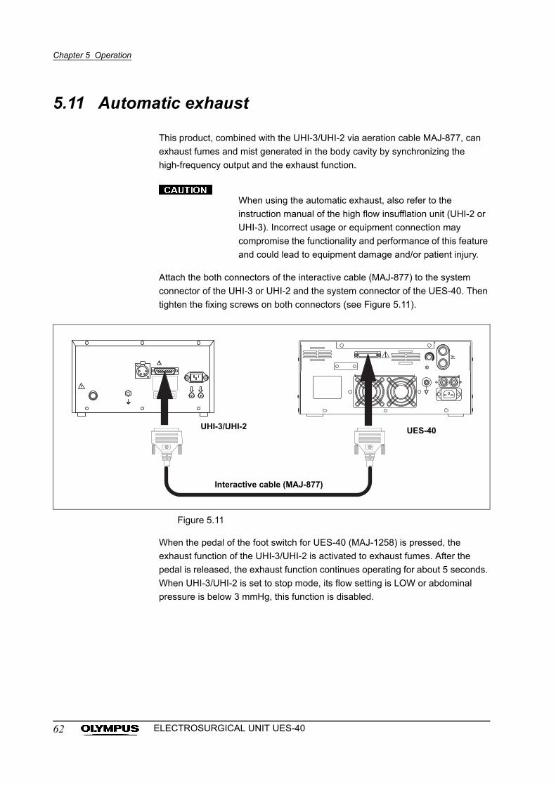
Chapter 5 Operation
5.11 Automatic exhaust
This product, combined with the UHI-3/UHI-2 via aeration cable MAJ-877, can
exhaust fumes and mist generated in the body cavity by synchronizing the
high-frequency output and the exhaust function.
When using the automatic exhaust, also refer to the
instruction manual of the high flow insufflation unit (UHI-2 or
UHI-3). Incorrect usage or equipment connection may
compromise the functionality and performance of this feature
and could lead to equipment damage and/or patient injury.
Attach the both connectors of the interactive cable (MAJ-877) to the system
connector of the UHI-3 or UHI-2 and the system connector of the UES-40. Then
tighten the fixing screws on both connectors (see Figure 5.11).
Figure 5.11
When the pedal of the foot switch for UES-40 (MAJ-1258) is pressed, the
exhaust function of the UHI-3/UHI-2 is activated to exhaust fumes. After the
pedal is released, the exhaust function continues operating for about 5 seconds.
When UHI-3/UHI-2 is set to stop mode, its flow setting is LOW or abdominal
pressure is below 3 mmHg, this function is disabled.
UHI-3/UHI-2
Interactive cable (MAJ-877)
UES-40
62 ELECTROSURGICAL UNIT UES-40
Chapter 5 Operation
• When the abdominal pressure exceeds the set pressure of
the UHI-3/UHI-2 by 5 mmHg, the excessive pressure warning
lamp of the UHI-3/UHI-2 will light and an alarm will sound.
• High-frequency output is performed under the assumption
that only the insufflation tube is inserted into the patient after
the first trocar is inserted (therefore, no suction tube is
connected). In this case, select the LOW flow setting or press
the STOP switch to temporarily disable the automatic
exhaust function.
5.12 Procedure after use
• Always discard used disposable patient plates. Never
attempt to reprocess or reuse them. It may cause patient
burns.
• Do not use the patient plate cable as a tool to remove the
patient plate from the patient. If utilized in this fashion, skin
injuries can occur.
If the UES-40 is not to be used for a long period, disconnect
the power cord plug from the hospital grade receptacle (wall
mains outlet).
1. Turn the power OFF.
2. When the foot switch is no longer needed, pull the ring on the foot switch
plug outward and disconnect the foot switch from the foot switch connector
on the rear panel of the UES-40.
Following monopolar treatment:
1. Following monopolar treatment, remove the patient plate from the patient
and disconnect the patient plate plug from the patient connector on the front
panel of the UES-40.
2. Following monopolar treatment, disconnect the plug of the hand piece from
hand piece connector 1 or hand piece connector 2 on the front panel of the
UES-40.
63ELECTROSURGICAL UNIT UES-40
Chapter 5 Operation
3. Following monopolar treatment, disconnect the A cord’s plug on the
accessory side from the accessory for the rigid endoscope, fiberscope or
videoscope. Disconnect the A cord’s plug on the UES-40 side from the
active connector on the front panel of the UES-40.
4. Following monopolar treatment, disconnect the A cord’s plug from the
accessory for use with fiberscopes, videoscopes or rigid endoscopes. Then
disconnect the A adapter’s plug from the active connector on the front panel
of the UES-40.
5. Turn the clamping screw counterclockwise and pull the A cord out from the
A cord end connection of the A adapter (MAJ-619, MAJ-620).
Following bipolar treatment:
Following bipolar treatment, disconnect the bipolar cord’s plug on the electrode
side from the bipolar electrode and disconnect the bipolar cord’s plug on the
UES-40 side from bipolar connector 1 or bipolar connector 2 on the front panel of
the UES-40.
Following saline treatment:
Following saline treatment, disconnect the saline cord’s plug on the electrode
side from the saline electrode and disconnect the saline cord’s plug on the
UES-40 side from the saline connector on the front panel of the UES-40.
64 ELECTROSURGICAL UNIT UES-40
Chapter 6 Care, Storage and Disposal
Chapter 6 Care, Storage and Disposal
After each use, perform the following cleaning procedures immediately. If
cleaning is delayed, debris encrustation may become a source of infection.
Encrustation may also result in electrosurgical unit malfunction.
For maintenance and storage of other optional items than those described
below, refer to the respective instruction manuals.
6.1 Care
After cleaning the electrosurgical unit, dry it thoroughly before
using it again. If it is used when wet, there is the risk of an
electric shock.
• Never immerse the electrosurgical unit in water, clean or
disinfect by immersion, gas sterilization or autoclaving. It may
cause equipment damage.
• Do not wipe the external surface with hard or abrasive wiping
material. The surface will be scratched.
1. Turn the electrosurgical unit OFF and disconnect the power cord from the
receptacle (wall mains outlet).
2. If the equipment is soiled with blood or other potentially infectious materials,
first wipe off all gross debris using neutral detergent, then wipe its surface
with a lint-free cloth moistened with a surface disinfectant.
3. To remove dust, dirt and non-patient debris, wipe the electrosurgical unit
and foot switch using a soft, lint-free cloth moistened with 70% ethyl or
isopropyl alcohol.
4. Make sure that the electrosurgical unit and foot switch are completely dry
before storage.
65ELECTROSURGICAL UNIT UES-40
Chapter 6 Care, Storage and Disposal
6.2 Storage
Do not store the electrosurgical unit in the shipping case.
Storing these devices in the humid and unventilated
environments of their shipping cases may encourage the
growth of microorganisms and pose an infection control risk.
• Do not store the electrosurgical unit in a location exposed to
direct sunlight, X ray, radioactivity, liquids or strong
electromagnetic radiation (e.g. near microwave medical
treatment equipment, short-wave medical treatment
equipment, MRI equipment, radio or mobile phones).
Damage to the electrosurgical unit may result.
• Do not apply excessive bending, straining, or squeezing
force to any cords during storage. It may cause malfunction.
1. Disconnect the power cord.
2. Store the equipment at room temperature in the horizontal position in a
clean, dry and stable location.
6.3 Care of A adapter 2
• The A adapter cannot be sterilized by ETO gas or
autoclaving. These methods will cause deformation and
damage that will render the A adapter useless.
• Make sure that foreign matter does not enter the A cord end
connection as this will result in poor connection.
1. After each procedure, wipe with a soft, clean, lint-free cloth. If dirt persists,
moisten the cloth with 70% ethyl or isopropyl alcohol and wipe again.
2. Dry thoroughly after wiping. An A adapter that is not completely dry may
cause an electric shock.
66 ELECTROSURGICAL UNIT UES-40
Chapter 6 Care, Storage and Disposal
6.4 Storage of A adapter 2
Never store the A adapter in the shipping box as this may
pose an infection control risk.
1. Store under the conditions given in “Specifications” in the Appendix, away
from direct sunlight and sources of liquids.
2. Store the A adapter with the clamping screw attached.
6.5 Disposal
When disposing of this electrosurgical unit, or any of its components (such as
fuses), follow all applicable national and local laws and guidelines.
67ELECTROSURGICAL UNIT UES-40
Chapter 7 Troubleshooting
Chapter 7 Troubleshooting
If the electrosurgical unit is visibly damaged, does not function as expected or is
found to have other irregularities during the inspection described in Chapter 3,
“Installation and Connection” and Chapter 4, “Inspection”, do not use the
electrosurgical unit. Contact Olympus.
Some problems that appear to be malfunctions may be correctable by referring
to Section 7.1, “Troubleshooting guide”.
If the problem cannot be resolved by the described remedial action, stop using
the electrosurgical unit and send it to Olympus for repair.
Olympus does not repair accessory parts. If an accessory part becomes
damaged, contact Olympus to purchase a replacement.
Never use the electrosurgical unit if an abnormality is
suspected. The patient can be fatally or seriously injured.
7.1 Troubleshooting guide
The following table shows the possible causes of and counter measures against
troubles that may occur due to equipment setting errors or deterioration of
consumables.
Troubles or failures due to other causes than those listed below should be
serviced. As repair performed by persons who are not qualified by Olympus
could cause patient or user injury and/or equipment damage, be sure to contact
Olympus for repair according to Section 7.3, “Returning the UES-40 for repair”.
68 ELECTROSURGICAL UNIT UES-40
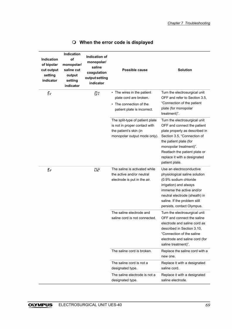
Chapter 7 Troubleshooting
When the error code is displayed
Indication
of bipolar
cut output
setting
indicator
Indication
of
monopolar/
saline cut
output
setting
indicator
Indication of
monopolar/
saline
coagulation
output setting
indicator
Possible cause Solution
• The wires in the patient
plate cord are broken.
• The connection of the
patient plate is incorrect.
Turn the electrosurgical unit
OFF and refer to Section 3.5,
“Connection of the patient
plate (for monopolar
treatment)”.
The split-type of patient plate
is not in proper contact with
the patient’s skin (in
monopolar output mode only).
Turn the electrosurgical unit
OFF and connect the patient
plate properly as described in
Section 3.5, “Connection of
the patient plate (for
monopolar treatment)”.
Reattach the patient plate or
replace it with a designated
patient plate.
The saline is activated while
the active and/or neutral
electrode is put in the air.
Use an electroconductive
physiological saline solution
(0.9% sodium chloride
irrigation) and always
immerse the active and/or
neutral electrode (sheath) in
saline. If the problem still
persists, contact Olympus.
The saline electrode and
saline cord is not connected.
Turn the electrosurgical unit
OFF and connect the saline
electrode and saline cord as
described in Section 3.10,
“Connection of the saline
electrode and saline cord (for
saline treatment)”.
The saline cord is broken. Replace the saline cord with a
new one.
The saline cord is not a
designated type.
Replace it with a designated
saline cord.
The saline electrode is not a
designated type.
Replace it with a designated
saline electrode.
69ELECTROSURGICAL UNIT UES-40
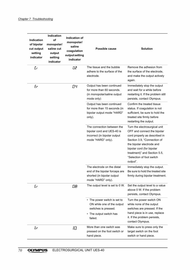
Chapter 7 Troubleshooting
The tissue and the bubble
adhere to the surface of the
electrode.
Remove the adhesion from
the surface of the electrode,
and make the output actively
again.
Output has been continued
for more than 60 seconds.
(in monopolar/saline output
mode only)
Immediately stop the output
and wait for a while before
restarting it. If the problem still
persists, contact Olympus.
Output has been continued
for more than 15 seconds (in
bipolar output mode “HARD”
only).
Confirm the treated tissue
status. If coagulation is not
sufficient, be sure to hold the
treated site firmly before
restarting the output.
The connection between the
bipolar cord and UES-40 is
incorrect (in bipolar output
mode “HARD” only).
Turn the electrosurgical unit
OFF and connect the bipolar
cord properly as described in
Section 3.9, “Connection of
the bipolar electrode and
bipolar cord (for bipolar
treatment)” and Section 5.5,
“Selection of foot switch
output”.
The electrode on the distal
end of the bipolar forceps are
shorted (in bipolar output
mode “HARD” only).
Immediately stop the output.
Be sure to hold the treated site
firmly during bipolar treatment.
The output level is set to 0 W. Set the output level to a value
above 0 W. If the problem
persists, contact Olympus.
• The power switch is set to
ON while one of the output
switches is pressed.
• The output switch has
failed.
Turn the power switch ON
while none of the output
switches are pressed. If the
hand piece is in use, replace
it. If the problem persists,
contact Olympus.
More than one switch was
pressed on the foot switch or
hand piece.
Make sure to press only the
target switch on the foot
switch or hand piece.
Indication
of bipolar
cut output
setting
indicator
Indication
of
monopolar/
saline cut
output
setting
indicator
Indication of
monopolar/
saline
coagulation
output setting
indicator
Possible cause Solution
70 ELECTROSURGICAL UNIT UES-40
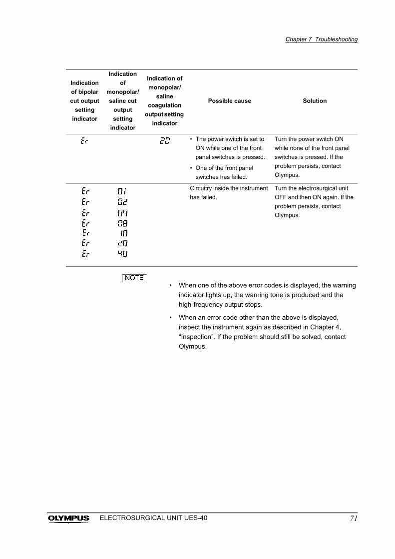
Chapter 7 Troubleshooting
• When one of the above error codes is displayed, the warning
indicator lights up, the warning tone is produced and the
high-frequency output stops.
• When an error code other than the above is displayed,
inspect the instrument again as described in Chapter 4,
“Inspection”. If the problem should still be solved, contact
Olympus.
• The power switch is set to
ON while one of the front
panel switches is pressed.
• One of the front panel
switches has failed.
Turn the power switch ON
while none of the front panel
switches is pressed. If the
problem persists, contact
Olympus.
Circuitry inside the instrument
has failed.
Turn the electrosurgical unit
OFF and then ON again. If the
problem persists, contact
Olympus.
Indication
of bipolar
cut output
setting
indicator
Indication
of
monopolar/
saline cut
output
setting
indicator
Indication of
monopolar/
saline
coagulation
output setting
indicator
Possible cause Solution
71ELECTROSURGICAL UNIT UES-40
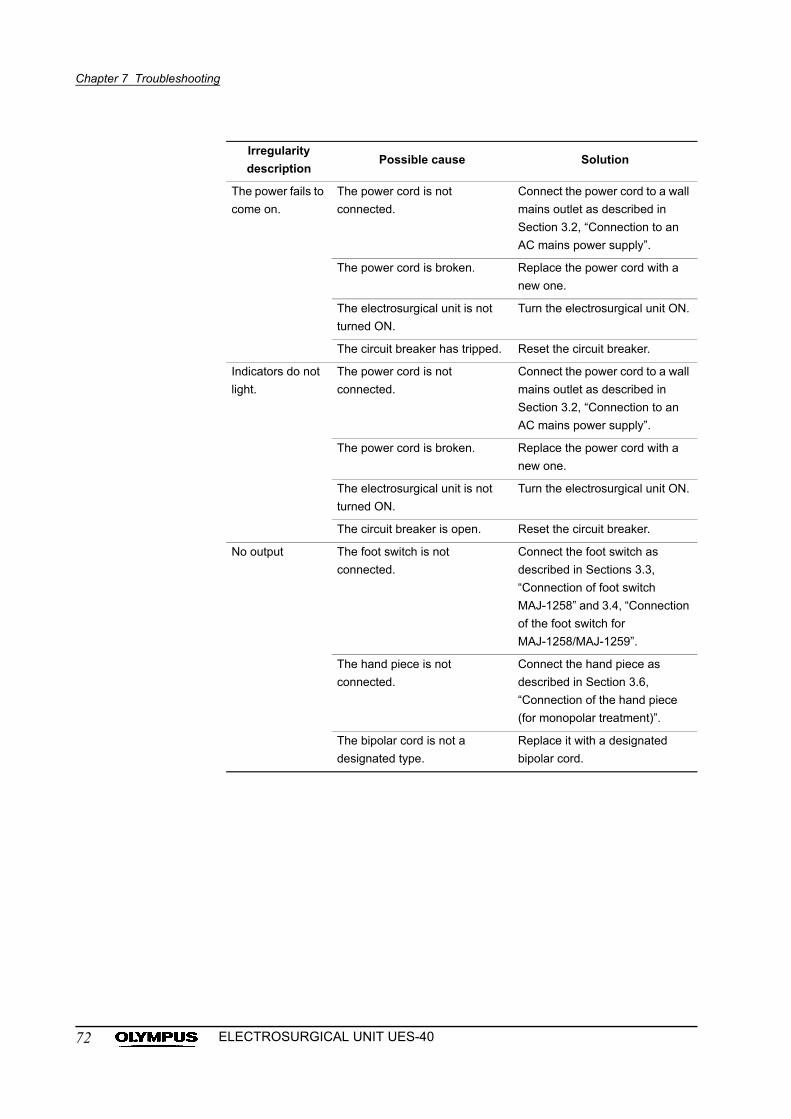
Chapter 7 Troubleshooting
Irregularity
descriptionPossible cause Solution
The power fails to
come on.
The power cord is not
connected.
Connect the power cord to a wall
mains outlet as described in
Section 3.2, “Connection to an
AC mains power supply”.
The power cord is broken. Replace the power cord with a
new one.
The electrosurgical unit is not
turned ON.
Turn the electrosurgical unit ON.
The circuit breaker has tripped. Reset the circuit breaker.
Indicators do not
light.
The power cord is not
connected.
Connect the power cord to a wall
mains outlet as described in
Section 3.2, “Connection to an
AC mains power supply”.
The power cord is broken. Replace the power cord with a
new one.
The electrosurgical unit is not
turned ON.
Turn the electrosurgical unit ON.
The circuit breaker is open. Reset the circuit breaker.
No output The foot switch is not
connected.
Connect the foot switch as
described in Sections 3.3,
“Connection of foot switch
MAJ-1258” and 3.4, “Connection
of the foot switch for
MAJ-1258/MAJ-1259”.
The hand piece is not
connected.
Connect the hand piece as
described in Section 3.6,
“Connection of the hand piece
(for monopolar treatment)”.
The bipolar cord is not a
designated type.
Replace it with a designated
bipolar cord.
72 ELECTROSURGICAL UNIT UES-40
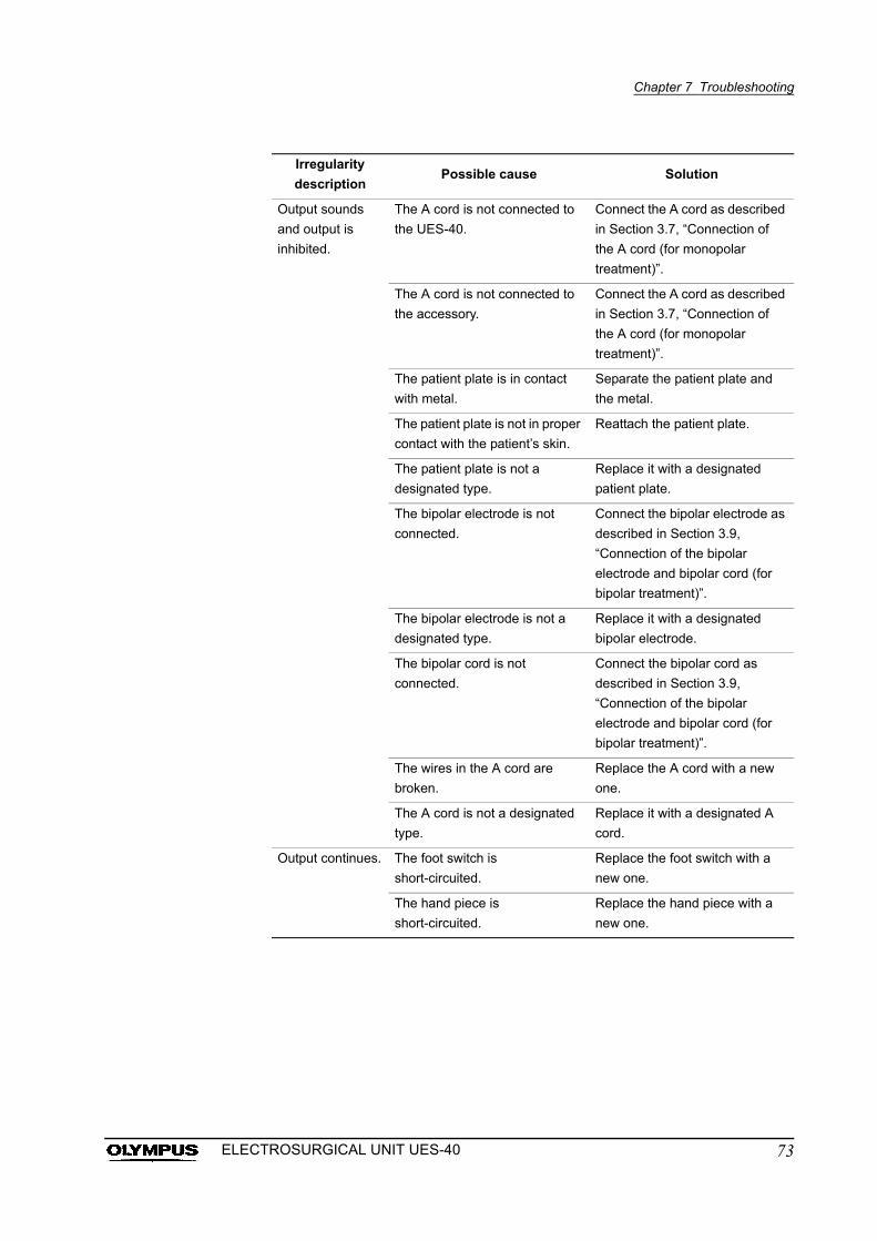
Chapter 7 Troubleshooting
Output sounds
and output is
inhibited.
The A cord is not connected to
the UES-40.
Connect the A cord as described
in Section 3.7, “Connection of
the A cord (for monopolar
treatment)”.
The A cord is not connected to
the accessory.
Connect the A cord as described
in Section 3.7, “Connection of
the A cord (for monopolar
treatment)”.
The patient plate is in contact
with metal.
Separate the patient plate and
the metal.
The patient plate is not in proper
contact with the patient’s skin.
Reattach the patient plate.
The patient plate is not a
designated type.
Replace it with a designated
patient plate.
The bipolar electrode is not
connected.
Connect the bipolar electrode as
described in Section 3.9,
“Connection of the bipolar
electrode and bipolar cord (for
bipolar treatment)”.
The bipolar electrode is not a
designated type.
Replace it with a designated
bipolar electrode.
The bipolar cord is not
connected.
Connect the bipolar cord as
described in Section 3.9,
“Connection of the bipolar
electrode and bipolar cord (for
bipolar treatment)”.
The wires in the A cord are
broken.
Replace the A cord with a new
one.
The A cord is not a designated
type.
Replace it with a designated A
cord.
Output continues. The foot switch is
short-circuited.
Replace the foot switch with a
new one.
The hand piece is
short-circuited.
Replace the hand piece with a
new one.
Irregularity
descriptionPossible cause Solution
73ELECTROSURGICAL UNIT UES-40
Chapter 7 Troubleshooting
• For a list of designated patient plates, refer to Section 3.5,
“Connection of the patient plate (for monopolar treatment)”.
• For a list of designated A cords, refer to Section 3.7,
“Connection of the A cord (for monopolar treatment)”.
• For a list of designated bipolar electrodes, refer to Section
3.9, “Connection of the bipolar electrode and bipolar cord (for
bipolar treatment)”.
• For a list of designated saline cords, refer to Section 3.10,
“Connection of the saline electrode and saline cord (for saline
treatment)”.
74 ELECTROSURGICAL UNIT UES-40
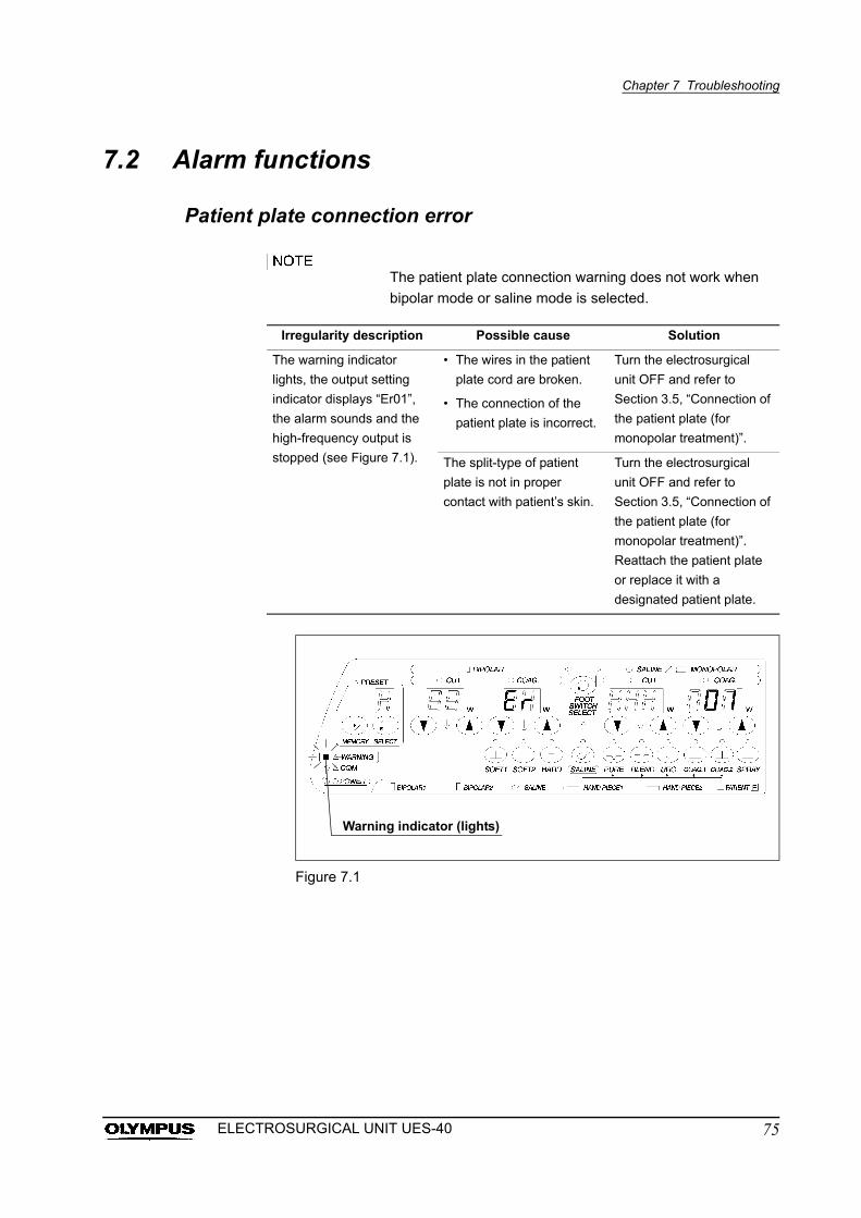
Chapter 7 Troubleshooting
7.2 Alarm functions
Patient plate connection error
The patient plate connection warning does not work when
bipolar mode or saline mode is selected.
Figure 7.1
Irregularity description Possible cause Solution
The warning indicator
lights, the output setting
indicator displays “Er01”,
the alarm sounds and the
high-frequency output is
stopped (see Figure 7.1).
• The wires in the patient
plate cord are broken.
• The connection of the
patient plate is incorrect.
Turn the electrosurgical
unit OFF and refer to
Section 3.5, “Connection of
the patient plate (for
monopolar treatment)”.
The split-type of patient
plate is not in proper
contact with patient’s skin.
Turn the electrosurgical
unit OFF and refer to
Section 3.5, “Connection of
the patient plate (for
monopolar treatment)”.
Reattach the patient plate
or replace it with a
designated patient plate.
Warning indicator (lights)
75ELECTROSURGICAL UNIT UES-40
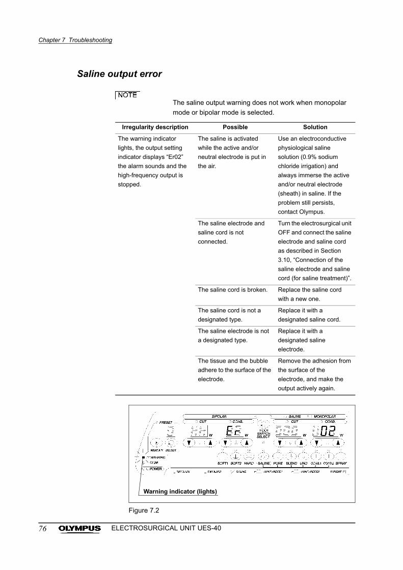
Chapter 7 Troubleshooting
Saline output error
The saline output warning does not work when monopolar
mode or bipolar mode is selected.
Figure 7.2
Irregularity description Possible Solution
The warning indicator
lights, the output setting
indicator displays “Er02”
the alarm sounds and the
high-frequency output is
stopped.
The saline is activated
while the active and/or
neutral electrode is put in
the air.
Use an electroconductive
physiological saline
solution (0.9% sodium
chloride irrigation) and
always immerse the active
and/or neutral electrode
(sheath) in saline. If the
problem still persists,
contact Olympus.
The saline electrode and
saline cord is not
connected.
Turn the electrosurgical unit
OFF and connect the saline
electrode and saline cord
as described in Section
3.10, “Connection of the
saline electrode and saline
cord (for saline treatment)”.
The saline cord is broken. Replace the saline cord
with a new one.
The saline cord is not a
designated type.
Replace it with a
designated saline cord.
The saline electrode is not
a designated type.
Replace it with a
designated saline
electrode.
The tissue and the bubble
adhere to the surface of the
electrode.
Remove the adhesion from
the surface of the
electrode, and make the
output actively again.
Warning indicator (lights)
76 ELECTROSURGICAL UNIT UES-40
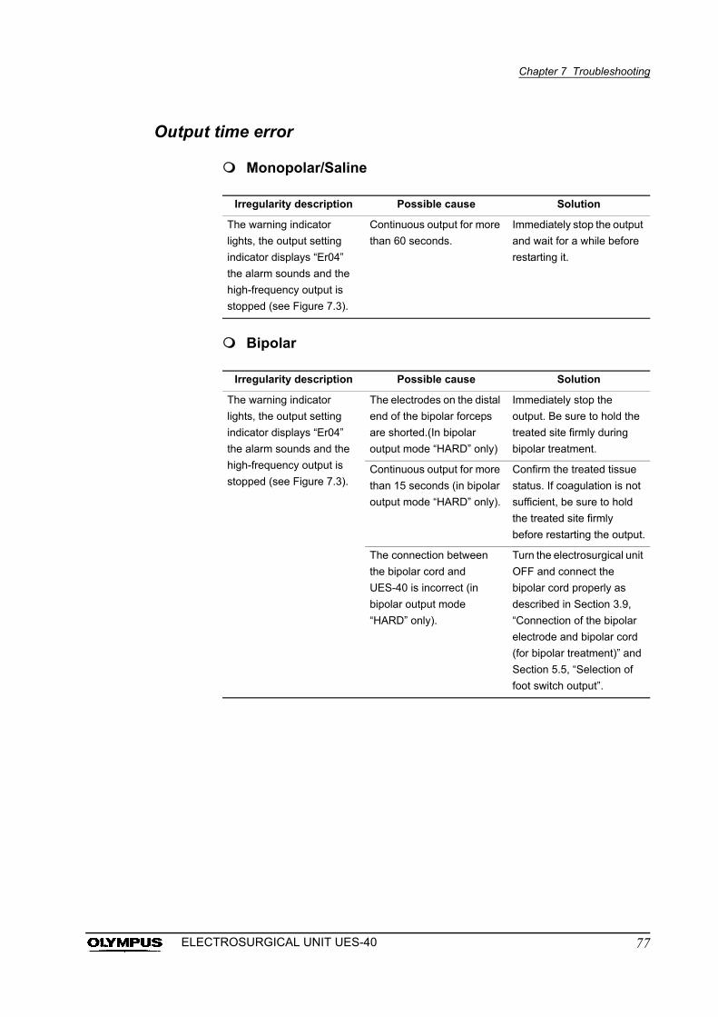
Chapter 7 Troubleshooting
Output time error
Monopolar/Saline
Bipolar
Irregularity description Possible cause Solution
The warning indicator
lights, the output setting
indicator displays “Er04”
the alarm sounds and the
high-frequency output is
stopped (see Figure 7.3).
Continuous output for more
than 60 seconds.
Immediately stop the output
and wait for a while before
restarting it.
Irregularity description Possible cause Solution
The warning indicator
lights, the output setting
indicator displays “Er04”
the alarm sounds and the
high-frequency output is
stopped (see Figure 7.3).
The electrodes on the distal
end of the bipolar forceps
are shorted.(In bipolar
output mode “HARD” only)
Immediately stop the
output. Be sure to hold the
treated site firmly during
bipolar treatment.
Continuous output for more
than 15 seconds (in bipolar
output mode “HARD” only).
Confirm the treated tissue
status. If coagulation is not
sufficient, be sure to hold
the treated site firmly
before restarting the output.
The connection between
the bipolar cord and
UES-40 is incorrect (in
bipolar output mode
“HARD” only).
Turn the electrosurgical unit
OFF and connect the
bipolar cord properly as
described in Section 3.9,
“Connection of the bipolar
electrode and bipolar cord
(for bipolar treatment)” and
Section 5.5, “Selection of
foot switch output”.
77ELECTROSURGICAL UNIT UES-40
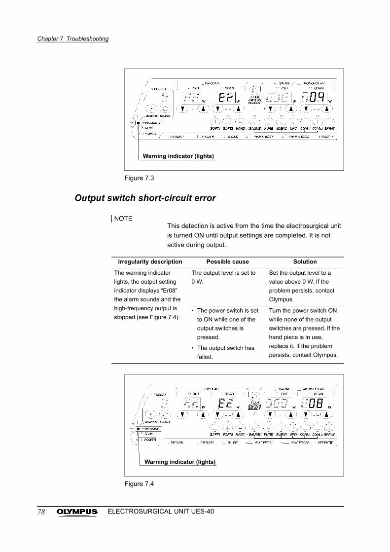
Chapter 7 Troubleshooting
Figure 7.3
Output switch short-circuit error
This detection is active from the time the electrosurgical unit
is turned ON until output settings are completed. It is not
active during output.
Figure 7.4
Irregularity description Possible cause Solution
The warning indicator
lights, the output setting
indicator displays “Er08”
the alarm sounds and the
high-frequency output is
stopped (see Figure 7.4).
The output level is set to
0 W.
Set the output level to a
value above 0 W. If the
problem persists, contact
Olympus.
• The power switch is set
to ON while one of the
output switches is
pressed.
• The output switch has
failed.
Turn the power switch ON
while none of the output
switches are pressed. If the
hand piece is in use,
replace it. If the problem
persists, contact Olympus.
Warning indicator (lights)
Warning indicator (lights)
78 ELECTROSURGICAL UNIT UES-40
Chapter 7 Troubleshooting
7.3 Returning the UES-40 for repair
Thoroughly clean this product before returning it for repair.
Improperly reprocessed equipment presents an infection
control risk to each person who handles the product within
the hospital or at Olympus.
Olympus is not liable for any injury or damage which occurs
as a result of repairs attempted by non-Olympus personnel.
When returning the UES-40 for repair, include a description of the malfunction or
damage and the name and telephone number of the individual at your location
who is most familiar with the problem. Also include a repair purchase order.
79ELECTROSURGICAL UNIT UES-40
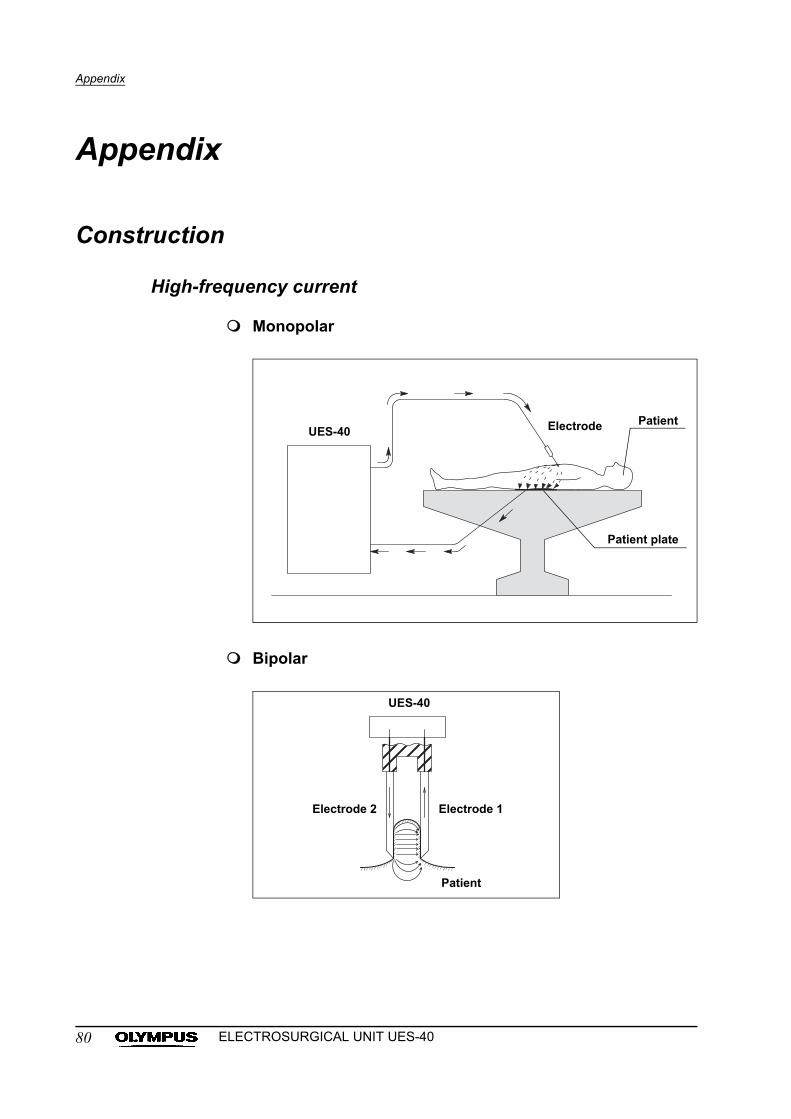
Appendix
Appendix
Construction
High-frequency current
Monopolar
Bipolar
UES-40 Electrode Patient
Patient plate
UES-40
Electrode 2 Electrode 1
Patient
80 ELECTROSURGICAL UNIT UES-40
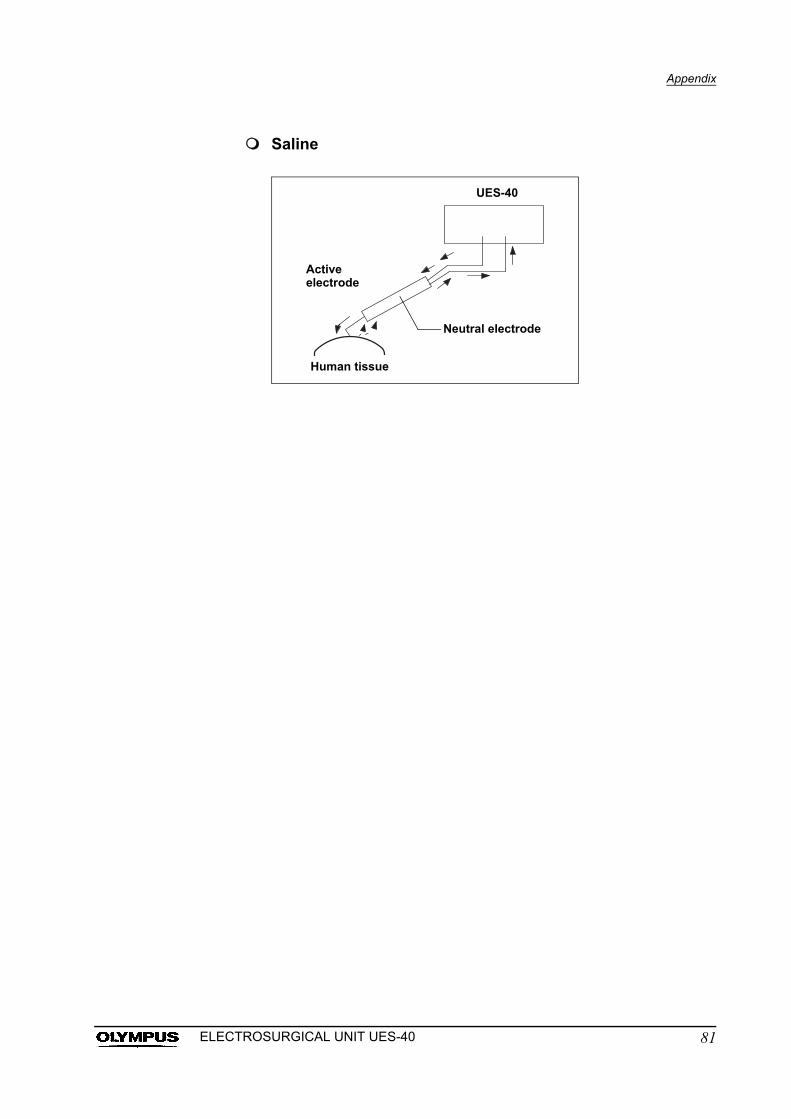
Appendix
Saline
UES-40
Neutral electrode
Human tissue
Active electrode
81ELECTROSURGICAL UNIT UES-40
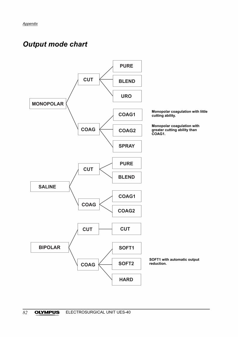
Appendix
Output mode chart
Monopolar coagulation with little cutting ability.
Monopolar coagulation with greater cutting ability than COAG1.
SOFT1 with automatic output reduction.
82 ELECTROSURGICAL UNIT UES-40
Appendix
System chart
The recommended combinations of equipment and accessories that can be
used with this instrument are listed below. New products released after the
introduction of this instrument may also be compatible for use in combination
with this instrument. For further details, contact Olympus.
If combinations of equipment other than those shown below
are used, the full responsibility is assumed by the medical
treatment facility.
83ELECTROSURGICAL UNIT UES-40
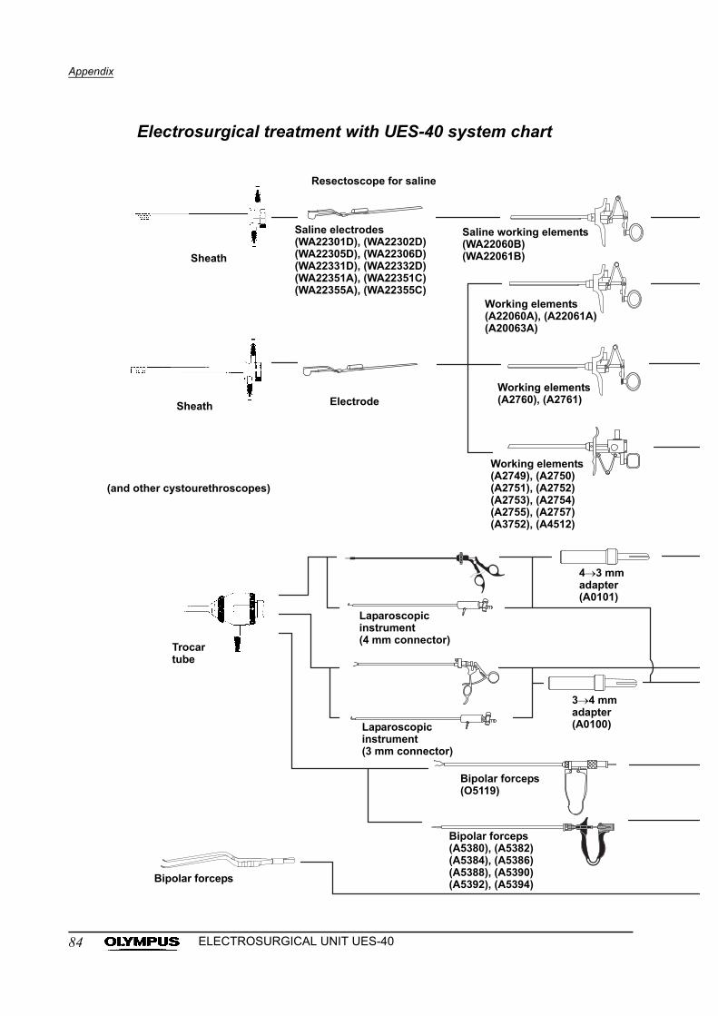
Appendix
Electrosurgical treatment with UES-40 system chart
Working elements(A2760), (A2761)
Sheath
Resectoscope for saline
Saline electrodes(WA22301D), (WA22302D)(WA22305D), (WA22306D)(WA22331D), (WA22332D)(WA22351A), (WA22351C)(WA22355A), (WA22355C)
Saline working elements(WA22060B)(WA22061B)
Working elements(A22060A), (A22061A)(A20063A)
Working elements(A2749), (A2750)(A2751), (A2752)(A2753), (A2754)(A2755), (A2757)(A3752), (A4512)
Electrode
(and other cystourethroscopes)
43 mmadapter(A0101)
Laparoscopic instrument(4 mm connector)
34 mmadapter(A0100)Laparoscopic
instrument(3 mm connector)
Bipolar forceps(O5119)
Bipolar forceps(A5380), (A5382)(A5384), (A5386)(A5388), (A5390)(A5392), (A5394)Bipolar forceps
Sheath
Trocar tube
84 ELECTROSURGICAL UNIT UES-40
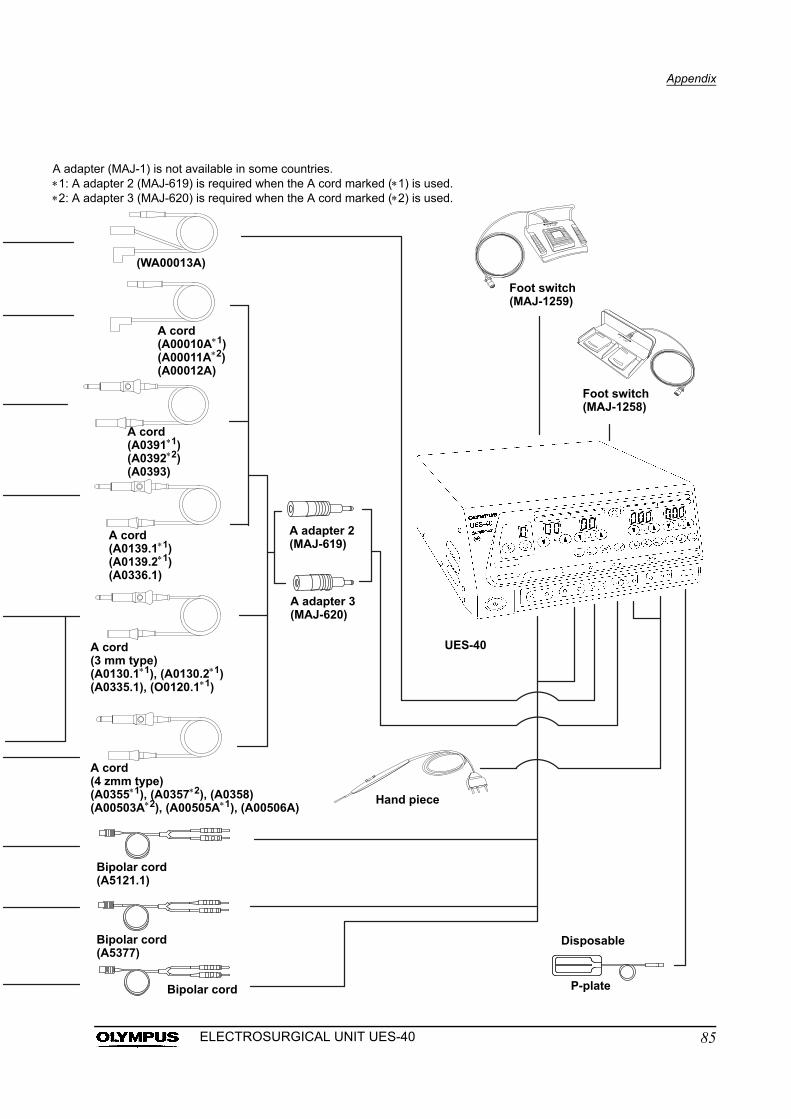
Appendix
A ada1: A 2: A
pter (MAJ-1) is not available in some countries.adapter 2 (MAJ-619) is required when the A cord marked (1) is used.adapter 3 (MAJ-620) is required when the A cord marked (2) is used.
(WA00013A)
Foot switch(MAJ-1259)
A adapter 2(MAJ-619)
A adapter 3(MAJ-620)
A cord(A00010A1)(A00011A2)(A00012A)
A cord(A03911)(A03922)(A0393)
A cord(A0139.11)(A0139.21)(A0336.1)
Foot switch(MAJ-1258)
UES-40
Hand piece
P-plateBipolar cord
Bipolar cord(A5121.1)
Bipolar cord(A5377)
A cord(4 zmm type)(A03551), (A03572), (A0358)(A00503A2), (A00505A1), (A00506A)
A cord(3 mm type)(A0130.11), (A0130.21)(A0335.1), (O0120.11)
Disposable
85ELECTROSURGICAL UNIT UES-40
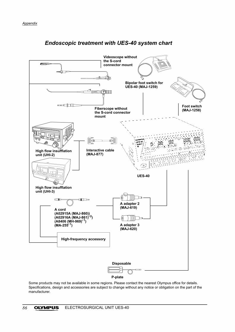
Appendix
Endoscopic treatment with UES-40 system chart
UES-40
Foot switch(MAJ-1258)
Bipolar foot switch for UES-40 (MAJ-1259)
Fiberscope without the S-cord connector mount
Videoscope without the S-cord connector mount
Interactive cable (MAJ-877)
High flow insufflation unit (UHI-2)
High flow insufflation unit (UHI-3)
A cord(A02915A (MAJ-860))(A02916A (MAJ-861)2)(A8406 (MH-969)1)(MA-2551)
A adapter 2(MAJ-619)
A adapter 3(MAJ-620)
High-frequency accessory
P-plate
Disposable
Some products may not be available in some regions. Please contact the nearest Olympus office for details. Specifications, design and accessories are subject to change without any notice or obligation on the part of the manufacturer.
86 ELECTROSURGICAL UNIT UES-40
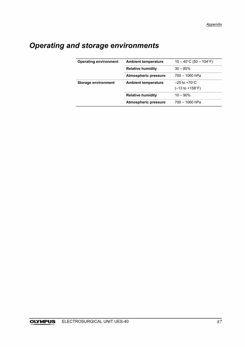
Appendix
Operating and storage environments
Operating environment Ambient temperature 10 – 40C (50 – 104F)
Relative humidity 30 – 85%
Atmospheric pressure 700 – 1060 hPa
Storage environment Ambient temperature –25 to +70C
(–13 to +158F)
Relative humidity 10 – 90%
Atmospheric pressure 700 – 1060 hPa
87ELECTROSURGICAL UNIT UES-40
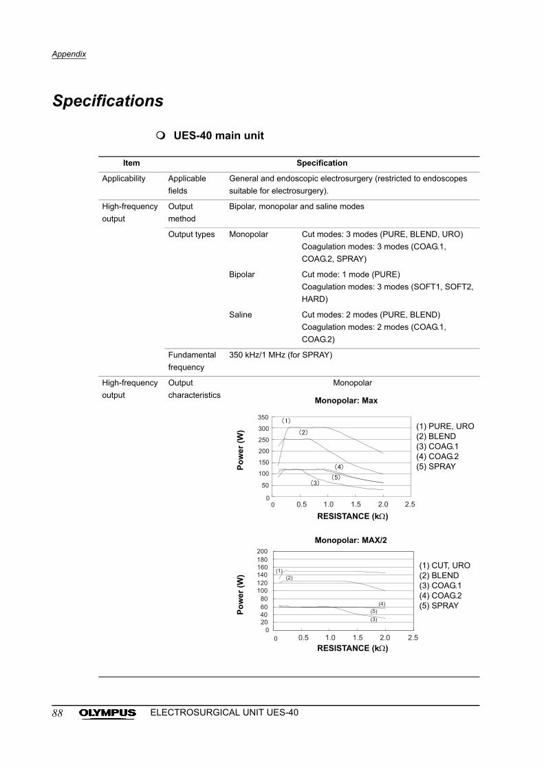
Appendix
Specifications
UES-40 main unit
Item Specification
Applicability Applicable
fields
General and endoscopic electrosurgery (restricted to endoscopes
suitable for electrosurgery).
High-frequency
output
Output
method
Bipolar, monopolar and saline modes
Output types Monopolar Cut modes: 3 modes (PURE, BLEND, URO)
Coagulation modes: 3 modes (COAG.1,
COAG.2, SPRAY)
Bipolar Cut mode: 1 mode (PURE)
Coagulation modes: 3 modes (SOFT1, SOFT2,
HARD)
Saline Cut modes: 2 modes (PURE, BLEND)
Coagulation modes: 2 modes (COAG.1,
COAG.2)
Fundamental
frequency
350 kHz/1 MHz (for SPRAY)
High-frequency
output
Output
characteristics
Monopolar
Po
wer
(W
)
Monopolar: Max
(1) PURE, URO(2) BLEND(3) COAG.1(4) COAG.2(5) SPRAY
RESISTANCE (k)
Po
wer
(W
)
(1) CUT, URO(2) BLEND(3) COAG.1(4) COAG.2(5) SPRAY
Monopolar: MAX/2
RESISTANCE (k)
88 ELECTROSURGICAL UNIT UES-40
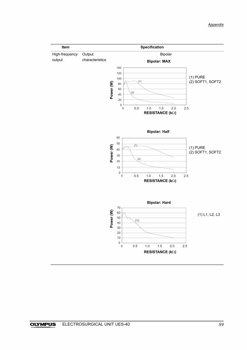
Appendix
Item Specification
High-frequency
output
Output
characteristics
Bipolar
Bipolar: MAX
(1) PURE(2) SOFT1, SOFT2
RESISTANCE (k)P
ow
er (
W)
Po
wer
(W
)
Bipolar: Half
Po
wer
(W
)
(1) PURE(2) SOFT1, SOFT2
(1) L1, L2, L3
Bipolar: Hard
RESISTANCE (k)
RESISTANCE (k)
89ELECTROSURGICAL UNIT UES-40
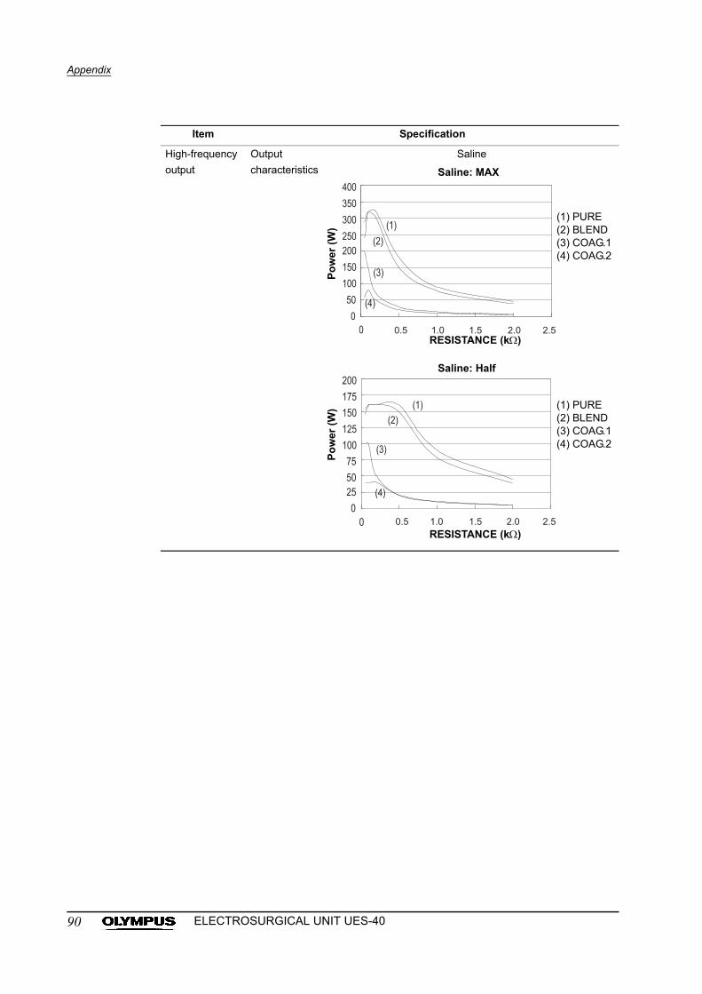
Appendix
Item Specification
High-frequency
output
Output
characteristics
Saline
Saline: MAX
(1) PURE(2) BLEND(3) COAG.1(4) COAG.2
RESISTANCE (k)P
ow
er (
W)
Po
wer
(W
)
Saline: Half
RESISTANCE (k)
(1) PURE(2) BLEND(3) COAG.1(4) COAG.2
90 ELECTROSURGICAL UNIT UES-40
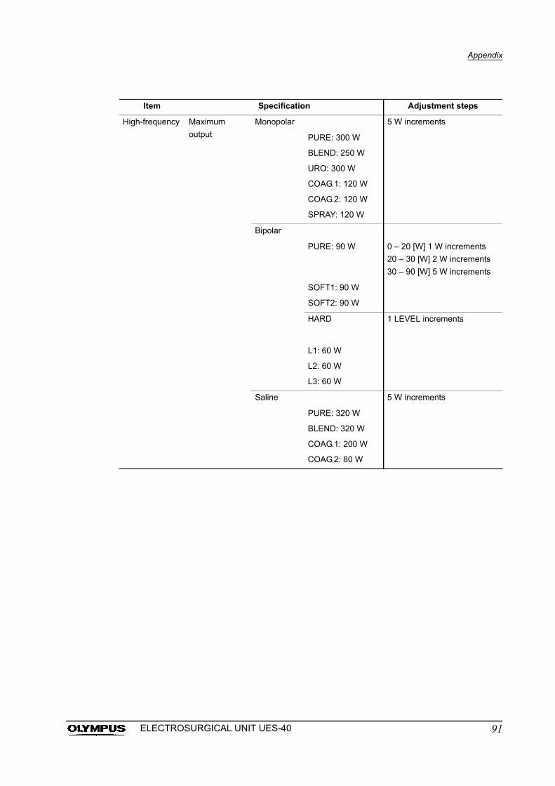
Appendix
Item Specification Adjustment steps
High-frequency Maximum
output
Monopolar 5 W increments
PURE: 300 W
BLEND: 250 W
URO: 300 W
COAG.1: 120 W
COAG.2: 120 W
SPRAY: 120 W
Bipolar
PURE: 90 W 0 – 20 [W] 1 W increments
20 – 30 [W] 2 W increments
30 – 90 [W] 5 W increments
SOFT1: 90 W
SOFT2: 90 W
HARD 1 LEVEL increments
L1: 60 W
L2: 60 W
L3: 60 W
Saline 5 W increments
PURE: 320 W
BLEND: 320 W
COAG.1: 200 W
COAG.2: 80 W
91ELECTROSURGICAL UNIT UES-40
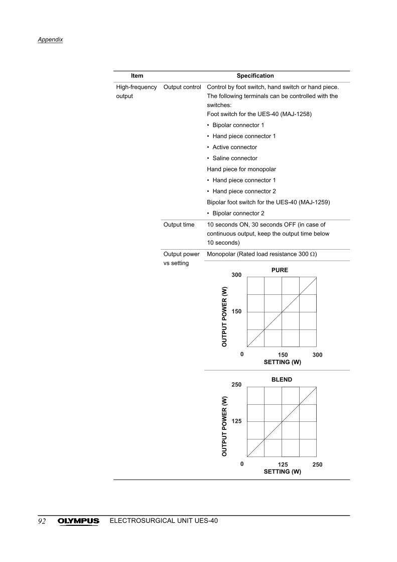
Appendix
Item Specification
High-frequency
output
Output control Control by foot switch, hand switch or hand piece.
The following terminals can be controlled with the
switches:
Foot switch for the UES-40 (MAJ-1258)
• Bipolar connector 1
• Hand piece connector 1
• Active connector
• Saline connector
Hand piece for monopolar
• Hand piece connector 1
• Hand piece connector 2
Bipolar foot switch for the UES-40 (MAJ-1259)
• Bipolar connector 2
Output time 10 seconds ON, 30 seconds OFF (in case of
continuous output, keep the output time below
10 seconds)
Output power
vs setting
Monopolar (Rated load resistance 300 )
PURE
SETTING (W)
OU
TP
UT
PO
WE
R (
W)
BLEND
SETTING (W)
OU
TP
UT
PO
WE
R (
W)
92 ELECTROSURGICAL UNIT UES-40
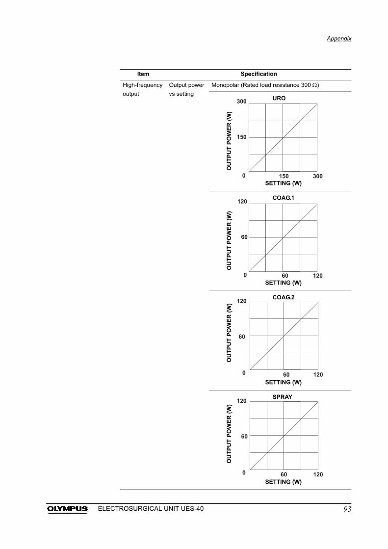
Appendix
Item Specification
High-frequency
output
Output power
vs setting
Monopolar (Rated load resistance 300 )
URO
SETTING (W)
OU
TP
UT
PO
WE
R (
W)
COAG.1
SETTING (W)
OU
TP
UT
PO
WE
R (
W)
COAG.2
SETTING (W)
OU
TP
UT
PO
WE
R (
W)
SPRAY
SETTING (W)
OU
TP
UT
PO
WE
R (
W)
93ELECTROSURGICAL UNIT UES-40
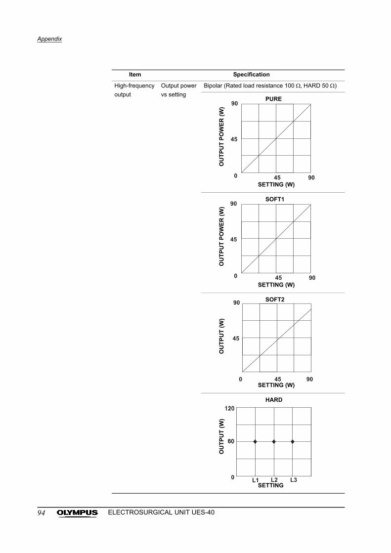
Appendix
Item Specification
High-frequency
output
Output power
vs setting
Bipolar (Rated load resistance 100 , HARD 50 )
PURE
SETTING (W)
OU
TP
UT
PO
WE
R (
W)
SOFT1
SETTING (W)
OU
TP
UT
PO
WE
R (
W)
SOFT2
SETTING (W)
OU
TP
UT
(W
)
HARD
SETTING
OU
TP
UT
(W
)
94 ELECTROSURGICAL UNIT UES-40
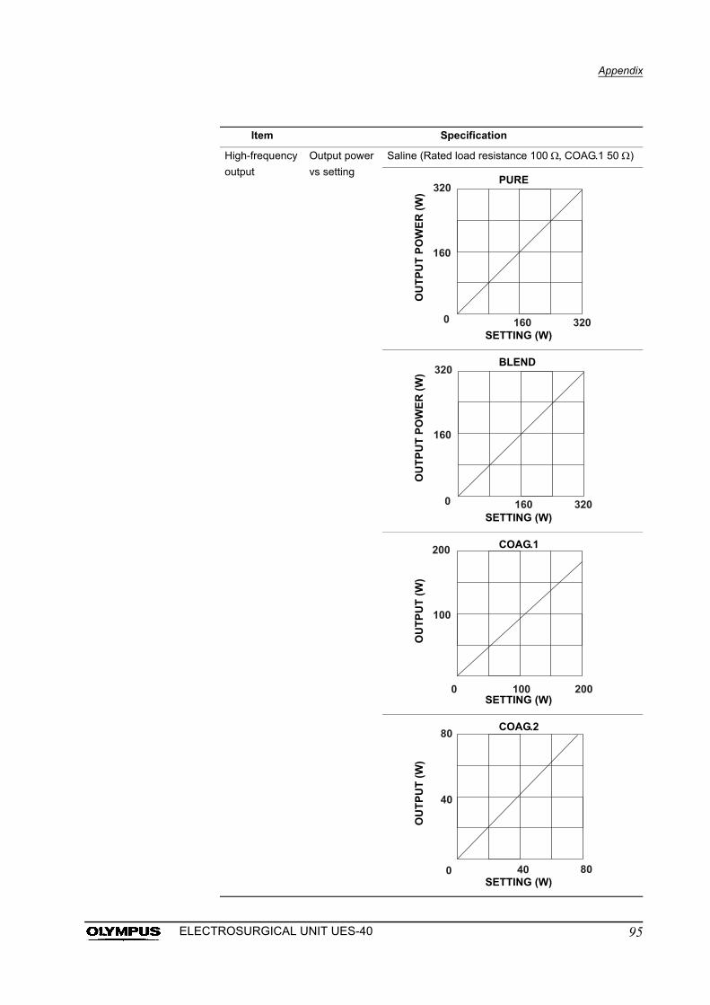
Appendix
Item Specification
High-frequency
output
Output power
vs setting
Saline (Rated load resistance 100 , COAG.1 50 )
PURE
SETTING (W)
OU
TP
UT
PO
WE
R (
W)
BLEND
SETTING (W)
OU
TP
UT
PO
WE
R (
W)
COAG.1
SETTING (W)
OU
TP
UT
(W
)
COAG.2
SETTING (W)
OU
TP
UT
(W
)
95ELECTROSURGICAL UNIT UES-40
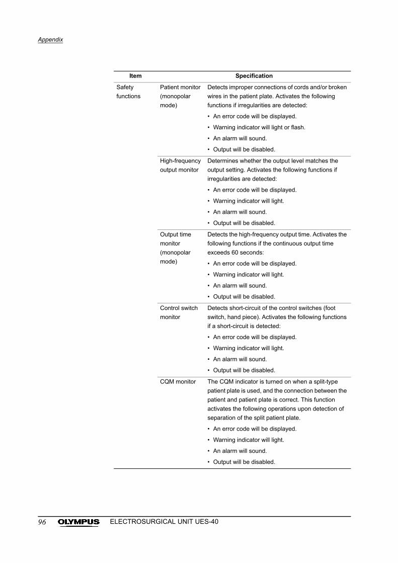
Appendix
Item Specification
Safety
functions
Patient monitor
(monopolar
mode)
Detects improper connections of cords and/or broken
wires in the patient plate. Activates the following
functions if irregularities are detected:
• An error code will be displayed.
• Warning indicator will light or flash.
• An alarm will sound.
• Output will be disabled.
High-frequency
output monitor
Determines whether the output level matches the
output setting. Activates the following functions if
irregularities are detected:
• An error code will be displayed.
• Warning indicator will light.
• An alarm will sound.
• Output will be disabled.
Output time
monitor
(monopolar
mode)
Detects the high-frequency output time. Activates the
following functions if the continuous output time
exceeds 60 seconds:
• An error code will be displayed.
• Warning indicator will light.
• An alarm will sound.
• Output will be disabled.
Control switch
monitor
Detects short-circuit of the control switches (foot
switch, hand piece). Activates the following functions
if a short-circuit is detected:
• An error code will be displayed.
• Warning indicator will light.
• An alarm will sound.
• Output will be disabled.
CQM monitor The CQM indicator is turned on when a split-type
patient plate is used, and the connection between the
patient and patient plate is correct. This function
activates the following operations upon detection of
separation of the split patient plate.
• An error code will be displayed.
• Warning indicator will light.
• An alarm will sound.
• Output will be disabled.
96 ELECTROSURGICAL UNIT UES-40
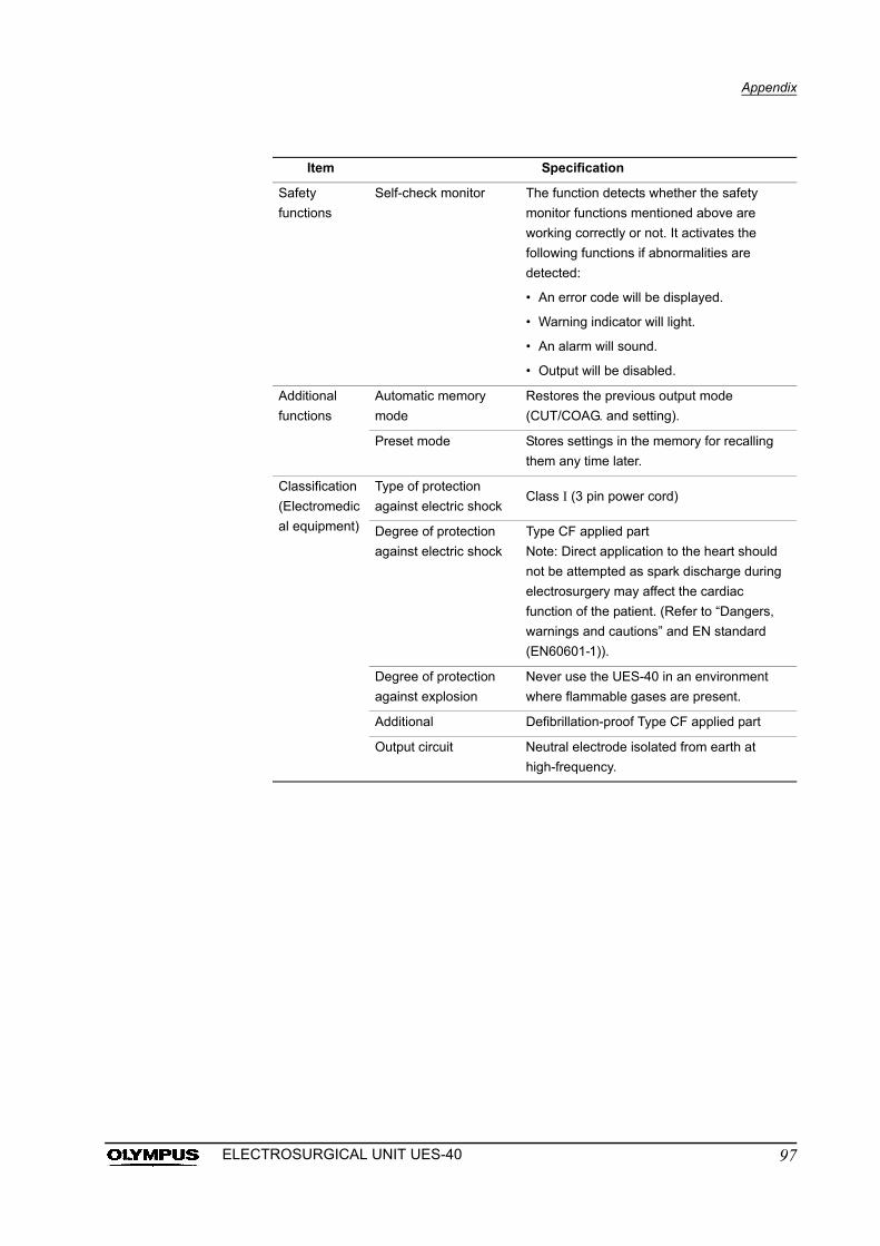
Appendix
Item Specification
Safety
functions
Self-check monitor The function detects whether the safety
monitor functions mentioned above are
working correctly or not. It activates the
following functions if abnormalities are
detected:
• An error code will be displayed.
• Warning indicator will light.
• An alarm will sound.
• Output will be disabled.
Additional
functions
Automatic memory
mode
Restores the previous output mode
(CUT/COAG. and setting).
Preset mode Stores settings in the memory for recalling
them any time later.
Classification
(Electromedic
al equipment)
Type of protection
against electric shockClass I (3 pin power cord)
Degree of protection
against electric shock
Type CF applied part
Note: Direct application to the heart should
not be attempted as spark discharge during
electrosurgery may affect the cardiac
function of the patient. (Refer to “Dangers,
warnings and cautions” and EN standard
(EN60601-1)).
Degree of protection
against explosion
Never use the UES-40 in an environment
where flammable gases are present.
Additional Defibrillation-proof Type CF applied part
Output circuit Neutral electrode isolated from earth at
high-frequency.
97ELECTROSURGICAL UNIT UES-40
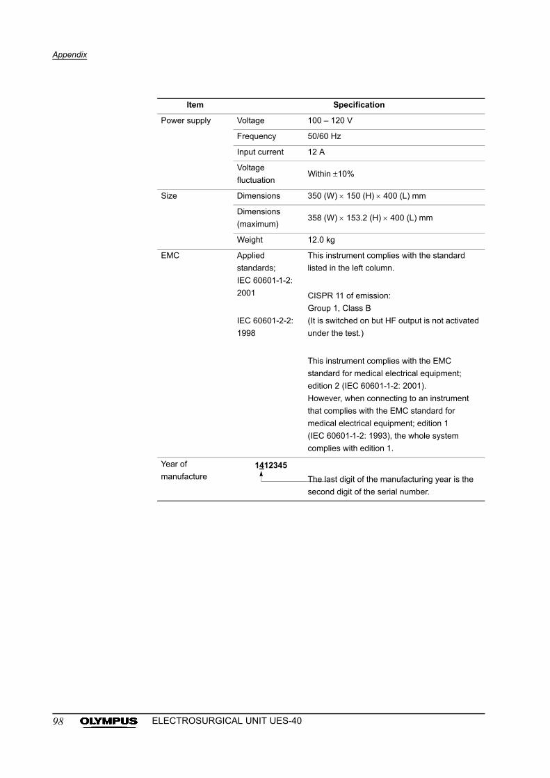
Appendix
Item Specification
Power supply Voltage 100 – 120 V
Frequency 50/60 Hz
Input current 12 A
Voltage
fluctuationWithin 10%
Size Dimensions 350 (W) 150 (H) 400 (L) mm
Dimensions
(maximum)358 (W) 153.2 (H) 400 (L) mm
Weight 12.0 kg
EMC Applied
standards;
IEC 60601-1-2:
2001
IEC 60601-2-2:
1998
This instrument complies with the standard
listed in the left column.
CISPR 11 of emission:
Group 1, Class B
(It is switched on but HF output is not activated
under the test.)
This instrument complies with the EMC
standard for medical electrical equipment;
edition 2 (IEC 60601-1-2: 2001).
However, when connecting to an instrument
that complies with the EMC standard for
medical electrical equipment; edition 1
(IEC 60601-1-2: 1993), the whole system
complies with edition 1.
Year of
manufacture The last digit of the manufacturing year is the
second digit of the serial number.
1412345
98 ELECTROSURGICAL UNIT UES-40
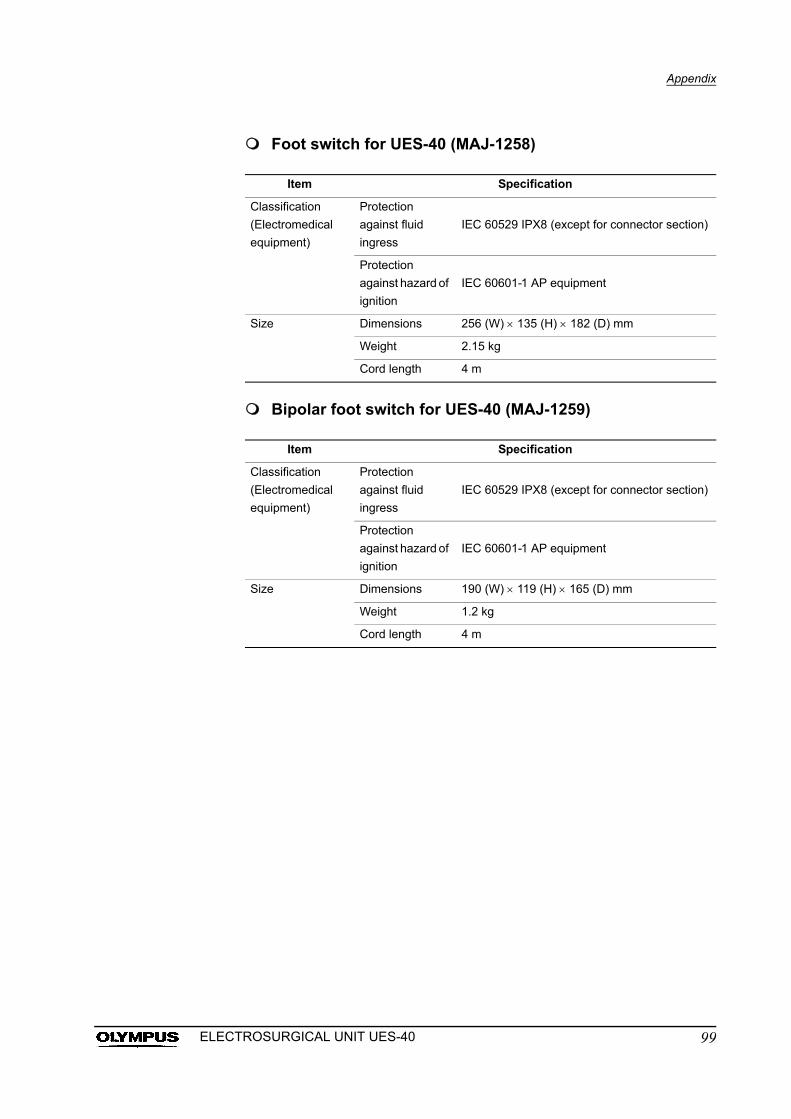
Appendix
Foot switch for UES-40 (MAJ-1258)
Bipolar foot switch for UES-40 (MAJ-1259)
Item Specification
Classification
(Electromedical
equipment)
Protection
against fluid
ingress
IEC 60529 IPX8 (except for connector section)
Protection
against hazard of
ignition
IEC 60601-1 AP equipment
Size Dimensions 256 (W) 135 (H) 182 (D) mm
Weight 2.15 kg
Cord length 4 m
Item Specification
Classification
(Electromedical
equipment)
Protection
against fluid
ingress
IEC 60529 IPX8 (except for connector section)
Protection
against hazard of
ignition
IEC 60601-1 AP equipment
Size Dimensions 190 (W) 119 (H) 165 (D) mm
Weight 1.2 kg
Cord length 4 m
99ELECTROSURGICAL UNIT UES-40
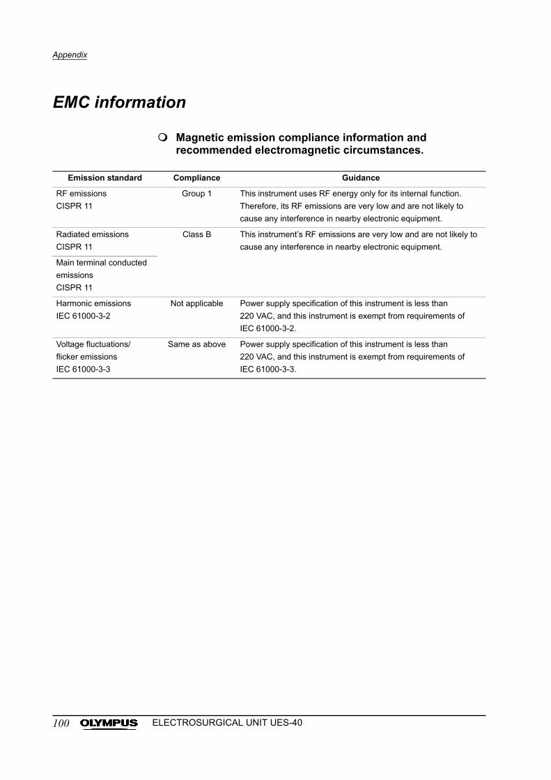
Appendix
EMC information
Magnetic emission compliance information and recommended electromagnetic circumstances.
Emission standard Compliance Guidance
RF emissions
CISPR 11
Group 1 This instrument uses RF energy only for its internal function.
Therefore, its RF emissions are very low and are not likely to
cause any interference in nearby electronic equipment.
Radiated emissions
CISPR 11
Class B This instrument’s RF emissions are very low and are not likely to
cause any interference in nearby electronic equipment.
Main terminal conducted
emissions
CISPR 11
Harmonic emissions
IEC 61000-3-2
Not applicable Power supply specification of this instrument is less than
220 VAC, and this instrument is exempt from requirements of
IEC 61000-3-2.
Voltage fluctuations/
flicker emissions
IEC 61000-3-3
Same as above Power supply specification of this instrument is less than
220 VAC, and this instrument is exempt from requirements of
IEC 61000-3-3.
100 ELECTROSURGICAL UNIT UES-40
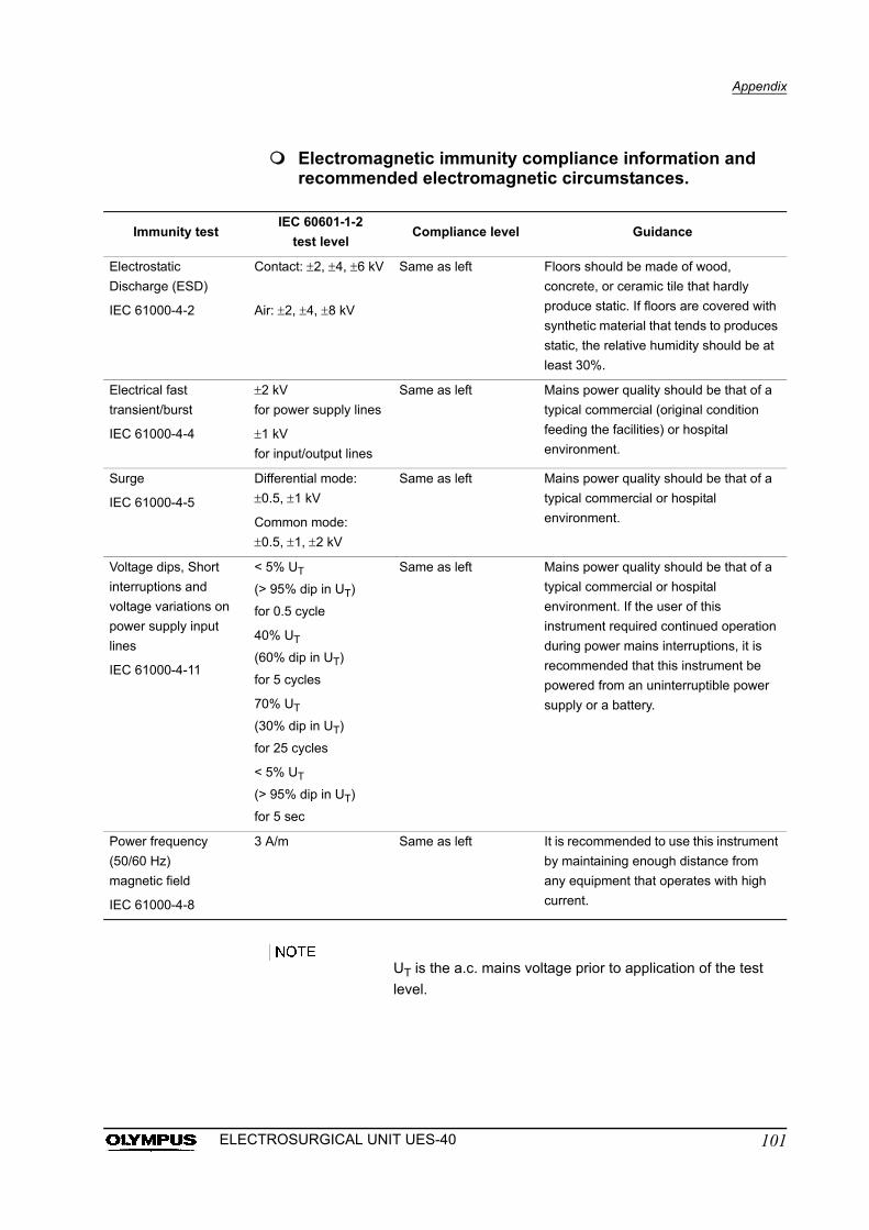
Appendix
Electromagnetic immunity compliance information and recommended electromagnetic circumstances.
UT is the a.c. mains voltage prior to application of the test
level.
Immunity testIEC 60601-1-2
test levelCompliance level Guidance
Electrostatic
Discharge (ESD)
IEC 61000-4-2
Contact: 2, 4, 6 kV
Air: 2, 4, 8 kV
Same as left Floors should be made of wood,
concrete, or ceramic tile that hardly
produce static. If floors are covered with
synthetic material that tends to produces
static, the relative humidity should be at
least 30%.
Electrical fast
transient/burst
IEC 61000-4-4
2 kV
for power supply lines
1 kV
for input/output lines
Same as left Mains power quality should be that of a
typical commercial (original condition
feeding the facilities) or hospital
environment.
Surge
IEC 61000-4-5
Differential mode:
0.5, 1 kV
Common mode:
0.5, 1, 2 kV
Same as left Mains power quality should be that of a
typical commercial or hospital
environment.
Voltage dips, Short
interruptions and
voltage variations on
power supply input
lines
IEC 61000-4-11
< 5% UT
(> 95% dip in UT)
for 0.5 cycle
40% UT
(60% dip in UT)
for 5 cycles
70% UT
(30% dip in UT)
for 25 cycles
< 5% UT
(> 95% dip in UT)
for 5 sec
Same as left Mains power quality should be that of a
typical commercial or hospital
environment. If the user of this
instrument required continued operation
during power mains interruptions, it is
recommended that this instrument be
powered from an uninterruptible power
supply or a battery.
Power frequency
(50/60 Hz)
magnetic field
IEC 61000-4-8
3 A/m Same as left It is recommended to use this instrument
by maintaining enough distance from
any equipment that operates with high
current.
101ELECTROSURGICAL UNIT UES-40
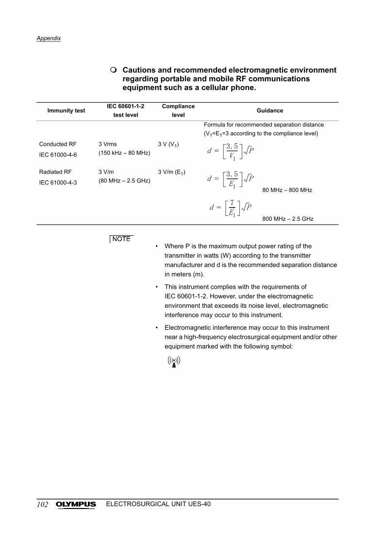
Appendix
Cautions and recommended electromagnetic environment regarding portable and mobile RF communications equipment such as a cellular phone.
• Where P is the maximum output power rating of the
transmitter in watts (W) according to the transmitter
manufacturer and d is the recommended separation distance
in meters (m).
• This instrument complies with the requirements of
IEC 60601-1-2. However, under the electromagnetic
environment that exceeds its noise level, electromagnetic
interference may occur to this instrument.
• Electromagnetic interference may occur to this instrument
near a high-frequency electrosurgical equipment and/or other
equipment marked with the following symbol:
Immunity testIEC 60601-1-2
test level
Compliance
levelGuidance
Formula for recommended separation distance
(V1=E1=3 according to the compliance level)
Conducted RF
IEC 61000-4-6
3 Vrms
(150 kHz – 80 MHz)
3 V (V1)
Radiated RF
IEC 61000-4-3
3 V/m
(80 MHz – 2.5 GHz)
3 V/m (E1)
80 MHz – 800 MHz
800 MHz – 2.5 GHz
d3.5V1
--------- P=
d3.5E1
--------- P=
d7E1----- P=
102 ELECTROSURGICAL UNIT UES-40
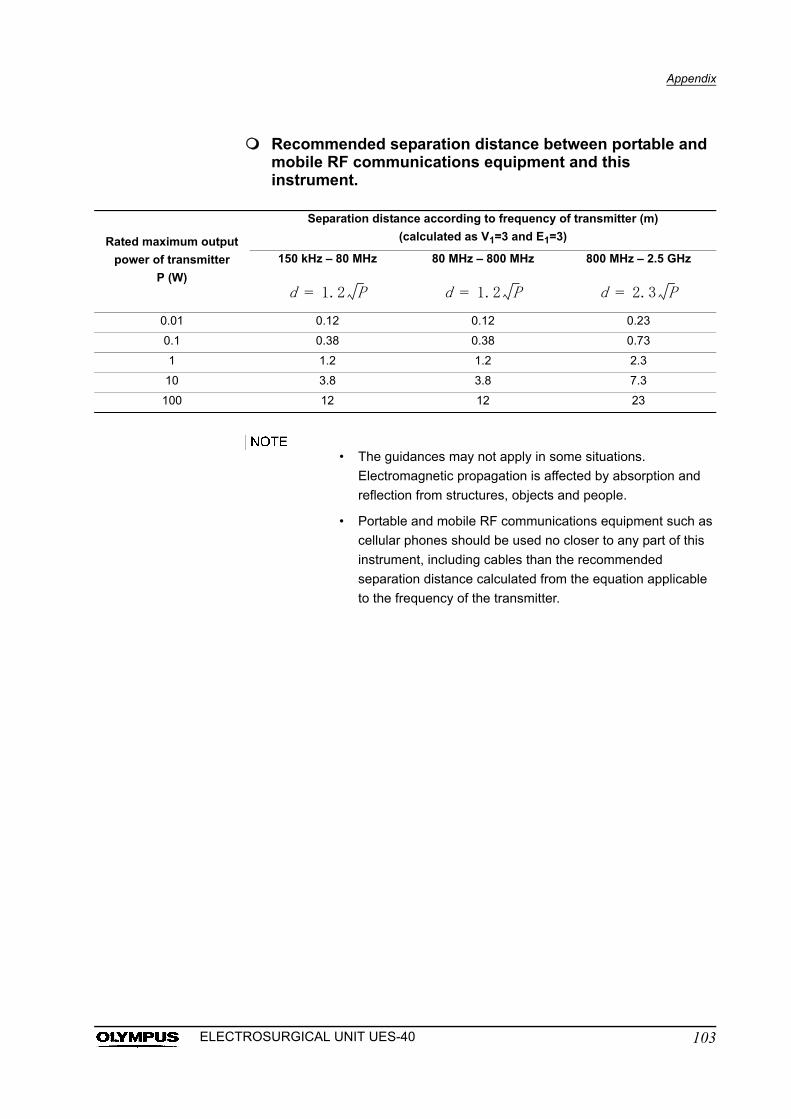
Appendix
Recommended separation distance between portable and mobile RF communications equipment and this instrument.
• The guidances may not apply in some situations.
Electromagnetic propagation is affected by absorption and
reflection from structures, objects and people.
• Portable and mobile RF communications equipment such as
cellular phones should be used no closer to any part of this
instrument, including cables than the recommended
separation distance calculated from the equation applicable
to the frequency of the transmitter.
Rated maximum output
power of transmitter
P (W)
Separation distance according to frequency of transmitter (m)
(calculated as V1=3 and E1=3)
150 kHz – 80 MHz 80 MHz – 800 MHz 800 MHz – 2.5 GHz
0.01 0.12 0.12 0.23
0.1 0.38 0.38 0.73
1 1.2 1.2 2.3
10 3.8 3.8 7.3
100 12 12 23
d 1.2 P= d 1.2 P= d 2.3 P=
103ELECTROSURGICAL UNIT UES-40

©1998 OLYMPUS MEDICAL SYSTEMS CORP. All rights reserved. No part of this publication may be reproduced or distributed without the express written permission of OLYMPUS MEDICAL SYSTEMS CORP.
OLYMPUS is a registered trademark of OLYMPUS CORPORATION.
Trademarks, product names, logos, or trade names used in this document are generally registered trademarks or trademarks of each company.

GT2
Printed in Japan 20110624 *0000902 07Manufactured by
2951 Ishikawa-cho, Hachioji-shi, Tokyo 192-8507, JapanFax: (042)646-2429 Telephone: (042)642-2111
(Premises/Goods delivery) Wendenstrasse 14-18, 20097 Hamburg, Germany(Letters) Postfach 10 49 08, 20034 Hamburg, Germany
3500 Corporate Parkway, P.O. Box 610, Center Valley, PA18034-0610, U.S.A.
Fax: (484)896-7128 Telephone: (484)896-5000
KeyMed House, Stock Road, Southend-on-Sea, Essex SS2 5QH, United KingdomFax: (01702)465677 Telephone: (01702)616333
491B, River Valley Road #12-01/04, Valley Point Office Tower, Singapore 248373Fax: 6834-2438 Telephone: 6834-0010
A8F, Ping An International Financial Center, No. 1-3, Xinyuan South Road,Chaoyang District, Beijing, 100027 P.R.C.
Fax: (86)10-5976-1299 Telephone: (86)10-5819-9000
117071, Moscow, Malaya Kaluzhskaya 19, bld. 1, fl.2, RussiaFax: (095)958-2277 Telephone: (095)958-2245
31 Gilby Road, Mount Waverley, VIC., 3149, AustraliaFax: (03)9543-1350 Telephone: (03)9265-5400
5301 Blue Lagoon Drive, Suite 290 Miami, FL 33126-2097, U.S.A.Fax: (305)261-4421 Telephone: (305)266-2332
Distributed by
Olympus-Tower, 114-9 Samseong-Dong, Gangnam-Gu, Seoul 135-090 KoreaFax: (02)6255-3494 Telephone: (02)6255-3210
Fax: (040)23773-4656 Telephone: (040)23773-0