Embed Size (px)
Citation preview
7/23/2019 Uenr4713uenr4713 Sis
http://slidepdf.com/reader/full/uenr4713uenr4713-sis 1/17
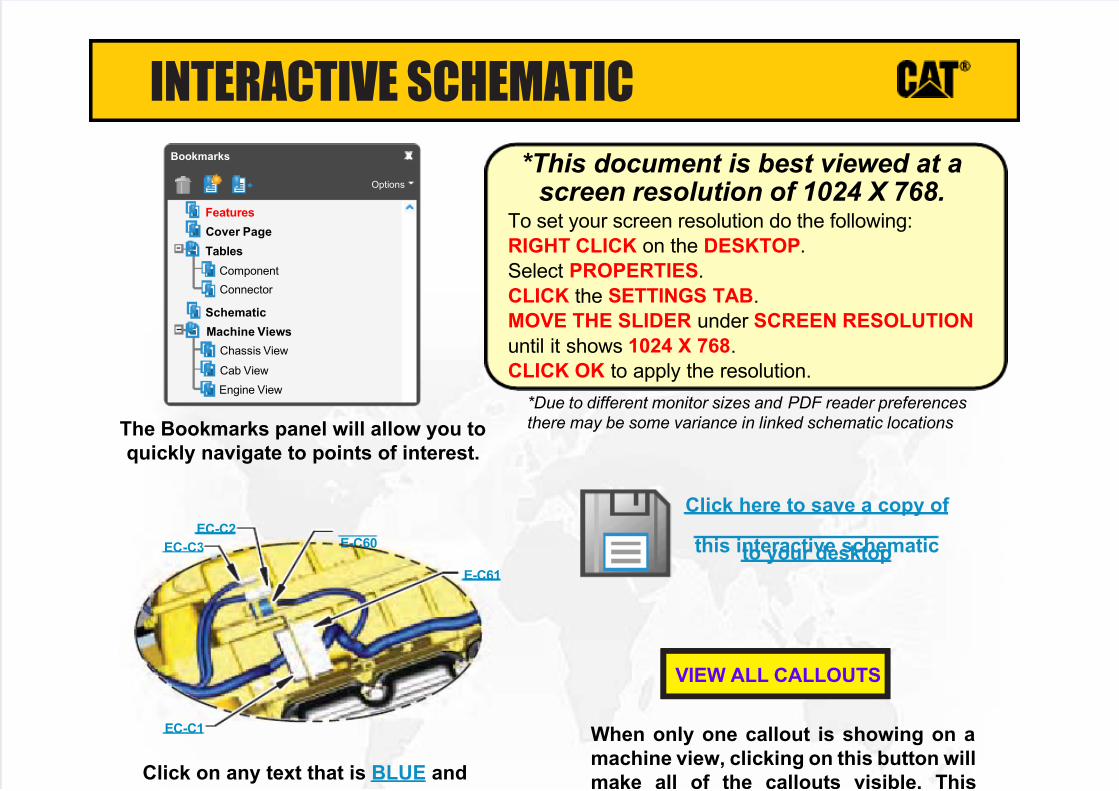
INTERACTIVE SCHEMATIC
The Bookmarks panel will allow you to
quickly navigate to points of interest.
Click on any text that is BLUE and
d li d Th h li k
When only one callout is showing on a
machine view, clicking on this button will
make all of the callouts visible. This
VIEW ALL CALLOUTS
Cover Page
Tables
Schematic
Machine Views
Component
Connector
Chassis View
Cab View
Engine View
Features
Options
Bookmarks X
EC-C3
EC-C2E-C60
EC-C1
E-C61
To set your screen resolution do the following:
RIGHT CLICK on the DESKTOP.
Select PROPERTIES.
CLICK the SETTINGS TAB.
MOVE THE SLIDER under SCREEN RESOLUTION
until it shows 1024 X 768.
CLICK OK to apply the resolution.
*This document is best viewed at a
screen resolution of 1024 X 768.
*Due to different monitor sizes and PDF reader preferences
there may be some variance in linked schematic locations
Click here to save a copy of
this interactive schematicto your desktop

7/23/2019 Uenr4713uenr4713 Sis
http://slidepdf.com/reader/full/uenr4713uenr4713-sis 2/17
d li d Th h li k
SCHEMATIC SYMBOLS AND DEFINITIONS
Spring
Control
Valves
Restriction Line Restriction
(Fixed)
2-Section
Pump
MAIN AUX.
Spring
(Adjustable)
Variability
Line Restriction
(Variable)
Pressure
Compensation
Pump: Variable and
Pressure Compensated
Hydraulic Pneumatic
Energy Triangles
Fluid
Conditioner
Attachment
Pump
or Motor
BASIC HYDRAULIC
COMPONENT SYMBOLS
Line Restriction
Variable and Pressure
Compensated
Pressure Temperature Flow
MEASUREMENT
Unidirectional Bidirectional
ROTATING SHAFTS
One Position Two Position Three Position
Two-way Three-Way Four-Way
ENVELOPES
PORTS
CONTROL
Basic
SymbolSpring
Loaded
Normal Position
A B
P T
A B
P T
Shifted Position Infinite Position
Shuttle Pilot
Controlled
VALVES
CHECK
Solenoid
or Manual
Solenoid
and Pilot
Solenoid and
Pilot or ManualSolenoid Servo Thermal Detent
COMBINATION CONTROLS
External Return Internal Return
Simplified CompleteInternal
Supply Pressure
RELEASED PRESSURE
REMOTE SUPPLY PRESSURE
PILOT CONTROL
Spring Loaded Gas Charged
ACCUMULATORS
Crossing Joining
LINES
Double ActingSingle Acting
CYLINDERSUnidirectional
Bidirectional
FIXED DISPLACEMENT
VARIABLE DISPLACEMENT
NON- COMPENSATED
PUMPS
Unidirectional
Bidirectional
Unidirectional
Bidirectional
FIXED DISPLACEMENT
VARIABLE DISPLACEMENT
NON- COMPENSATED
MOTORS
Unidirectional
Bidirectional
Two
Position
Infinite
Positioning
FLOW IN ONE
DIRECTION
FLOW ALLOWED IN
EITHER DIRECTION
Three
Position
CROSS
FLOW
PARALLEL
FLOW
INTERNAL PASSAGEWAYS
7/23/2019 Uenr4713uenr4713 Sis
http://slidepdf.com/reader/full/uenr4713uenr4713-sis 3/17
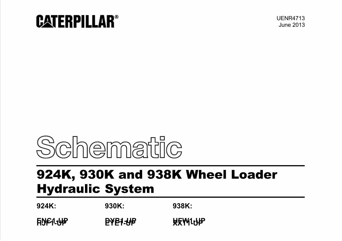
UENR4713June 2013
924K, 930K and 938K Wheel Loader Hydraulic System
924K:
ENC1-UPHJF1-UP
930K:
DYB1-UPEYE1-UP
938K:
HFW1-UPXXT1-UP
7/23/2019 Uenr4713uenr4713 Sis
http://slidepdf.com/reader/full/uenr4713uenr4713-sis 4/17
COMPONENT TABLE
Description Part NumberMachine
Location
Schematic
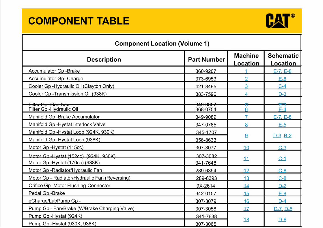
Location Accumulator Gp -Brake 360-9207 1 E-7, E-8
Accumulator Gp -Charge 373-6953 2 E-6
Cooler Gp -Hydraulic Oil (Clayton Only) 421-8495 3 C-4
Cooler Gp -Transmission Oil (938K) 383-7596 4 D-3
Filter Gp -Gearbox 349-3667 5 E-3Filter Gp -Hydraulic Oil 368-0754 6 E-4
Manifold Gp -Brake Accumulator 349-9089 7 E-7, E-8
Manifold Gp -Hystat Interlock Valve 347-0785 8 E-5
Manifold Gp -Hystat Loop (924K, 930K) 345-1707
Manifold Gp -Hystat Loop (938K) 356-8633
Motor Gp -Hystat (115cc) 307-3077 10 C-3
Motor Gp -Hystat (152cc) (924K, 930K) 307-3082
Motor Gp -Hystat (170cc) (938K) 341-7648
Motor Gp -Radiator/Hydraulic Fan 289-6394 12 C-8
Motor Gp - Radiator/Hydraulic Fan (Reversing) 289-6393 13 C-8
Orifice Gp -Motor Flushing Connector 9X-2614 14 D-2
Pedal Gp -Brake 342-0157 15 E-8
eCharge/LubPump Gp - 307-3079 16 D-4
Pump Gp - Fan/Brake (W/Brake Charging Valve) 307-3058 17 D-7, D-8
Pump Gp -Hystat (924K) 341-7638
Pump Gp -Hystat (930K, 938K) 307-3065
9 D-3, B-2
18 D-6
Component Location (Volume 1)
11 C-1
7/23/2019 Uenr4713uenr4713 Sis
http://slidepdf.com/reader/full/uenr4713uenr4713-sis 5/17
COMPONENT TABLE
Description Part NumberMachine
Location
Schematic
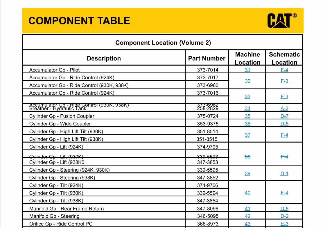
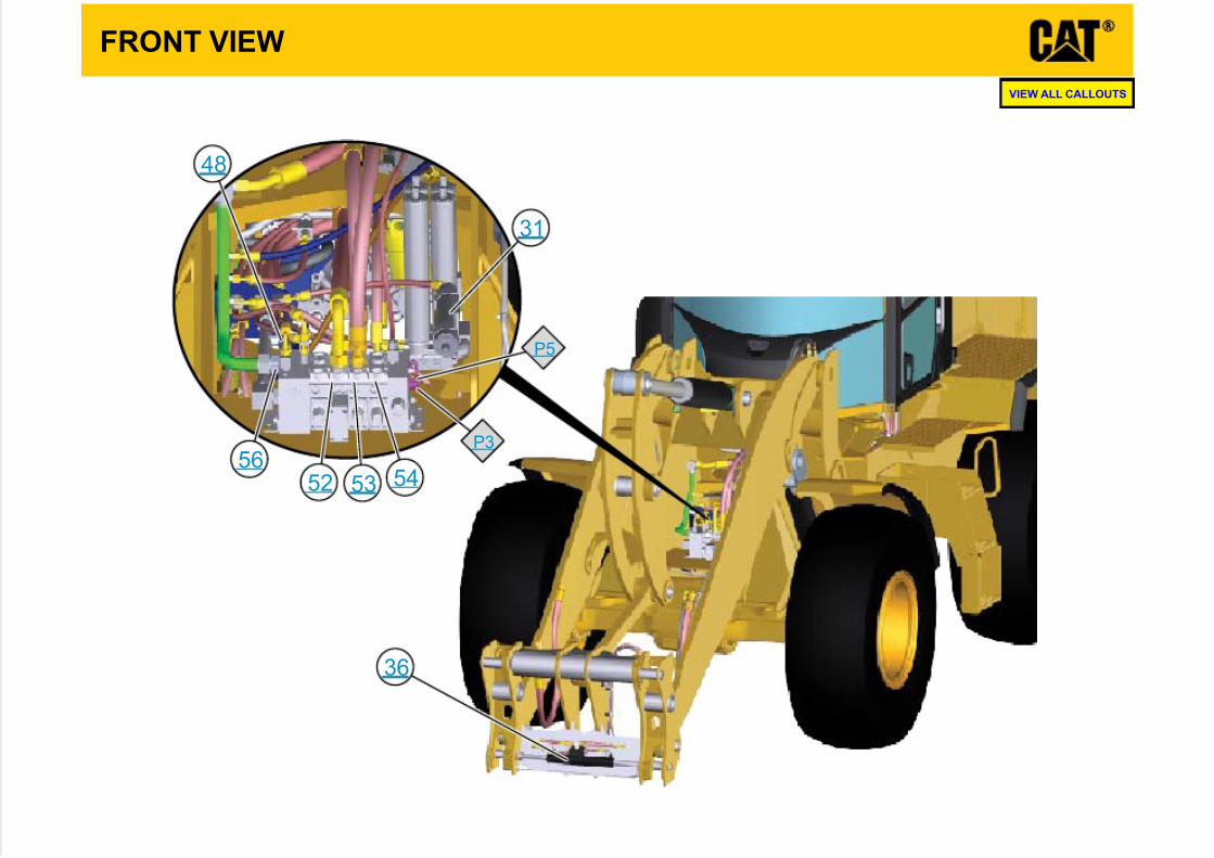
Location Accumulator Gp - Pilot 373-7014 31 F-4
Accumulator Gp - Ride Control (924K) 373-7017
Accumulator Gp - Ride Control (930K, 938K) 373-6960
Accumulator Gp - Ride Control (924K) 373-7016
Accumulator Gp - Ride Control (930K, 938K) 373-6962Breather - Hydraulic Tank 258-2829 34 A-2
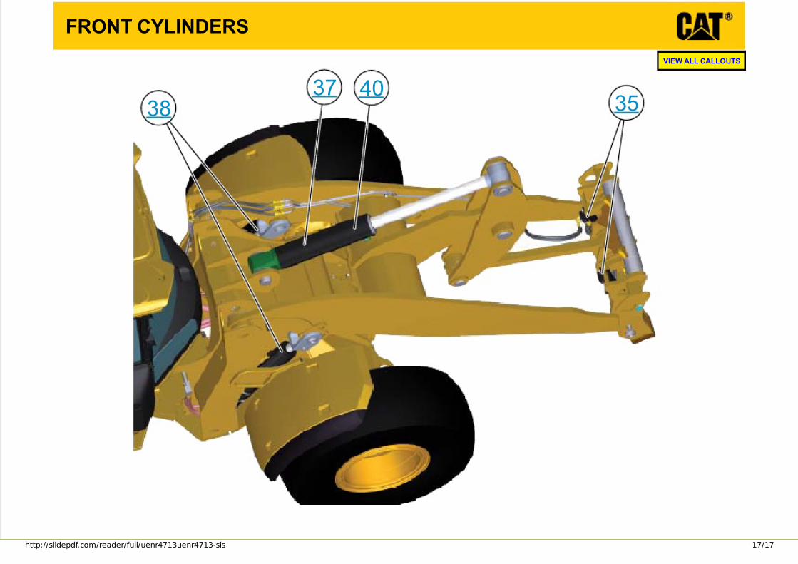
Cylinder Gp - Fusion Coupler 375-0724 35 D-7
Cylinder Gp - Wide Coupler 353-9375 36 D-5
Cylinder Gp - High Lift Tilt (930K) 351-8514
Cylinder Gp - High Lift Tilt (938K) 351-8515
Cylinder Gp - Lift (924K) 374-9705
Cylinder Gp - Lift (930K) 339-5593Cylinder Gp - Lift (938K0 347-3853
Cylinder Gp - Steering (924K, 930K) 339-5595
Cylinder Gp - Steering (938K) 347-3852
Cylinder Gp - Tilt (924K) 374-9706
Cylinder Gp - Tilt (930K) 339-5594
Cylinder Gp - Tilt (938K) 347-3854
Manifold Gp - Rear Frame Return 347-8096 41 D-8
Manifold Gp - Steering 346-5095 42 D-2
Orifice Gp - Ride Control PC 366-8973 43 E-3
32 F-3
F-4
40 F-4
37 F-4
F-3
Component Location (Volume 2)
39 D-1
33
38
7/23/2019 Uenr4713uenr4713 Sis
http://slidepdf.com/reader/full/uenr4713uenr4713-sis 6/17
TAP TABLE
Tap
Number Description
Schematic
Location
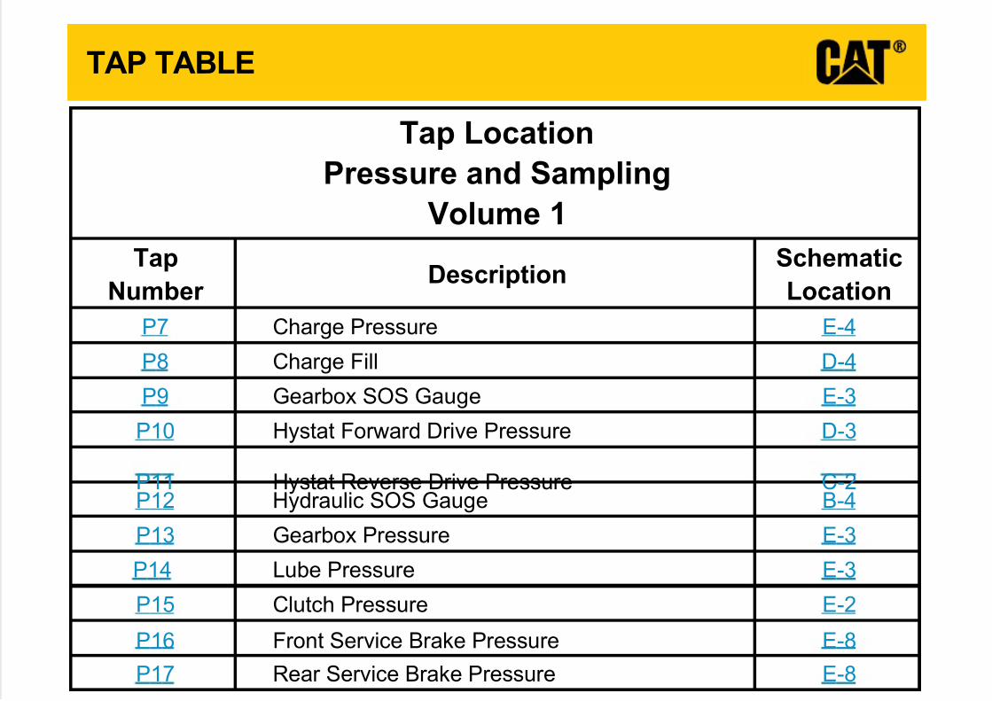
4-Eer usser Pegr ahC7P
4-DlliFegr ahC8P
3-EegauGSOSxobr aeG9P
3-Der usser Pevir Ddr awr oFtatsyH01P
2-Cer usser Pevir Desr eveRtatsyH11P4-BegauGSOSciluar dyH21P
3-Eer usser Pxobr aeG31P
3-Eer usser PebuL41P
2-Eer usser PhctulC51P
8-Eer usser Pekar Becivr eStnor F61P
8-Eer usser Pekar Becivr eSr aeR71P
Tap Location
Pressure and Sampling
Volume 1
7/23/2019 Uenr4713uenr4713 Sis
http://slidepdf.com/reader/full/uenr4713uenr4713-sis 7/17
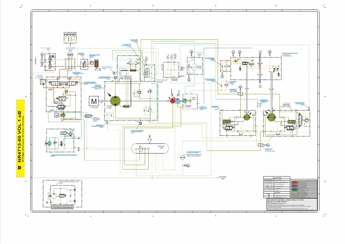
U E
N R 4 7 1 3 - 0 0 V O L 1 o f 2
3 0 P a g e , ( D i m e n s i o n s : 3 9 i n c h e s x 2 8 i n c h e s )
12345678
A
B
C
D
E
F
12345678
A
B
C
D
E
F
LINE PATTERNS
Drain/ ReturnLines
Component Group
Pilot / LoadSensingPressure
PressureLine
Attachment
AirLine
CALLOUTS
Taps (Pressure, Sampling, Sensor-by letter)
Components(By number)
YY
52
HYDRAULICCIRCUIT COLORDESCRIPTIONS
PILOT PUMP OUTPUT
LUBE PUMP SUPPLY CIRCUIT
MAINPUMP OUTPUT
LUBE PUMP CIRCUIT
AUXILIARY 1CIRCUIT
LOADSENSE CIRCUIT
STEERING CIRCUIT
FAN/BRAKE CHARGE PUMP
SUPPLY LINE
QUICK COUPLERCIRCUIT
BRAKE CIRCUIT
AUXILIARY 2CIRCUIT
DRAIN/ RETURNLINE
TILT CYLINDERCIRCUIT
LIFT CYLINDERCIRCUIT
HYSTAT CIRCUIT
Components areshowninstalledona fully operablemachinewiththekey and engineoff, transmissionshifter inneutralandwithparkingbrakeset.
RefertotheappropriateServiceManualforTroubleshooting, Specifications andSystems Operations.
VOLUME 1of 2:DRIVE CIRCUITS
SCHEMATICPART NUMBER: 423-4719, CHANGE: 00, VERSION: --
924K, 930KAND 938KWHEEL LOADERHYDRAULIC SYSTEM
MEDIA NUMBER: UENR4713-00
Note: RefertotheParts Manualusinga specific serialnumberprefix inSIS beforeorderingparts fromthis schematic.
M
SW
P
A1 A2
B
R
L
A
T1
U
G
B
T1T2
F
PU L
T1
E
SMs
Mp
M
SecondarySteer
S t e e r i n g
I m p l e m e n t
ChargePump
LubePump
HystatPump
S e c .
S t e e r i n g
Rear DrainManifold
F r o n t
M a n i f o l d
HMU
P i l o t D r a i n
D u a l M o d e
S t e e r i n g
ToImpPilot
T2
HydraulicTank
ToRear Axle
ToFront Axle
U
BM1
G
A
M1
B1 B2
S2
S1
SOS
Y
Z
U
TE
G
SA
1:1Drive Ratio
307-3077
(938k): 341-7648
(938k): 356-8633
388-9447
VALVE GP-HIGHALTITUDE(NOT SHOWN)
349-1178
421-8495:(CLAYTONONLY)
9X-2614
370-2280
358-3002:(938k)
307-3079
368-0754
349-3667
366-8955
123-4750
347-0785
(930k, 938k): 307-3065
349-1178
373-6953
T
P
G
C
Fan Brake
Valve
B
L
R
T o
B r a k e s
360-9207342-0157
349-9089
344-7391
357-0377
344-7391
289-3054
(12)MOTORGP -RADIATOR/HYDRAULICFAN
289-6393
307-3058 383-7596
385-9391
348-2078
Fan Motor (Standard)
(924k)341-7 638
337-7053:(924k, 930k)
(924k, 930k): 307-3082
423-3531:( CAMP LARGO ONLY)
345-1707:(9 24K, 930K)
(26)VALVE-CHECK PILOTSUPPLY
(8)MANIFOLDGP HYSTATINTERLOCK
P9
P8
(10)MOTORGPHYSTAT(115cc)
(9)MANIFOLDGPHYSTATLOOP
(9)MANIFOLDGP HYSTATLOOP
(21)SENSORGP-PRESSUREHYSTATLOOP(REVERSE)
(3)COOLERGP -HYDRAULICOIL
(25)VALVE GP-CHECKHYSTATFLUSHING
(23)TRANSMISSIONAR-GEARBOX
(16)PUMPGPCHARGE & LUBE
(6)FILTERGP-OIL
HYDOIL
(5)FILTERGP-O (BSC)GEARBOX
(29)VALVE GP-SOLENOIDHYSTATINTERLOCK
(18)PUMPGP HYSTATPUMP
(20)SENSORGP-PRESS HYSTAT LOOP(FORWARD)
(2)ACCUMULATORGPCHARGE ACCUMULATOR
(14)ORIFICE GPMOTORFLUSHING
(11)MOTORGPHYSTAT(170cc)
(1)ACCUMULATORGP BRAKE ACCUMULATOR
(15)PEDALGP-BRAKE
(7)MANIFOLDGP BRAKE ACCUMULATOR
(22)SENSORGP-PRESSPARK BRAKE
(28)VALVE GP PARK BRAKE
(19)SENSORGPPRESSURE
(BRAKE CHARGE)
(13)MOTORGP -RADIATOR/HYDRAULICFAN(REVERSING)
(17)PUMPGP- FAN/BRAKE(W/ BRAKE CHARGING VALVE)
(4)COOLERGPXMSNOIL
(27)VALVE GP -CHECK(COOLERBYPASS)
P12
P11
P15P14P13P7
P16
P17
P10
(24)VALVE GP-HYDOILCOOLERBYPASS
(30)COOLERGP -HYDRAULICOIL
7/23/2019 Uenr4713uenr4713 Sis
http://slidepdf.com/reader/full/uenr4713uenr4713-sis 8/17
U E
N R 4 7 1 3 - 0 0 V O L 2 o f 2
3 0 P a g e , ( D i m e n s i o n s : 3 9 i n c h e s x 2 8 i n c h e s )
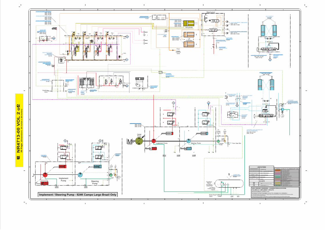
Components areshowninstalledona fully operablemachinewiththekey andengineoff, transmissionshifter inneutralandwithparkingbrakeset.
RefertotheappropriateServiceManualforTroubleshooting, Specifications andSystems Operations.
VOLUME 2of 2:IMPLEMENT CIRCUITS
SCHEMATICPART NUMBER: 423-4719, CHANGE: 00, VERSION: --
924K, 930KAND 938KWHEEL LOADERHYDRAULICSYSTEM
MEDIA NUMBER: UENR4713-00
Note: RefertotheParts Manualusinga specific serialnumberprefix inSIS beforeorderingparts fromthis schematic.
12345678
A
B
C
D
E
F
12345678
A
B
C
D
E
F
LINE PATTERNS
Drain/ ReturnLines
Component Group
Pilot / LoadSensingPressure
PressureLine
Attachment
AirLine
CALLOUTS
Taps (Pressure, Sampling, Sensor-by letter)
Components (By number)
YY
52
HYDRAULICCIRCUIT COLORDESCRIPTIONS
PILOT PUMP OUTPUT
LUBE PUMP SUPPLY CIRCUIT
MAINPUMP OUTPUT
LUBE PUMP CIRCUIT
AUXILIARY 1CURCUIT
LOADSENSE CIRCUIT
STEERING CIRCUIT
FAN/BRAKE CHARGE PUMP
SUPPLY LINE
QUICK COUPLERCIRCUIT
BRAKE CIRCUIT
DIFFERENTIALLOCK CIRCUIT
AUXILIARY 2CURCUIT
DRAIN/ RETURNLINE
TILT CYLINDERCIRCUIT
LIFT CYLINDERCIRCUIT
HYSTAT CIRCUIT
M
L1S1
L4 L3
S2
LubePump
ChargePump
P
H
R
T S
Ride Control
HystatPump
M
Tilt Cylinder
Fan Motor Return
Cooler Return
Fan/BrakeSuction
To
GearBox
From Gear Box
Park BrakeValve
TP LS PP
C1 C2
To
Pp
P
CS
RCS
Lx
Ls
A AB B B
Tilt Lift Aux
1
T
C1
C2LS
P
LiftCylinders
L2
T
C2C1
P
LP RP
D
SB
B1 B2
B1 B2
S2
T
From
HystatInterlock
Valve
ToChargeCircuit
R
E
AB A
Aux
Tg
Steering PumpImplement Pump
X2
PG
X1
PPG
GP
Fan Motor Case Drain
Brake PedalValve
1:1DriveRatio
2
353-9375
375-0724
352-1108192-2684
6V-7238347-8096
352-1045
344-7391
(938K): 347-2352
349-8199
(50)TANK GPHYDRAULICTANK
258-2829
247-4503
344-7391
175-0447
9T-1013
346-5095
349-7843
366-8973
280-9978
9T-1013
373-7014
112-1817
307-3051
P
T
DL
Cooler Bypass
TP LS P P
LP RP
347-3852
9T-1013
L1S1 L4 L3S2
Steering
Pump
X2
L2
B1 B2
LubePump
ChargePump
FromGearBox
B1 B2
S2
ToChargeCircuit
Implement
Pump
X1
Implement / Steering Pump - 924K Campo Largo Brazil Only
ToGear Box
378-2838378-2847
(930K): 343-3048(924K): 343-3047
(938K): 347-3853(930K): 343-3050(924K): 343-3049
(938K): 347-3854(930K): 343-3052(924K): 343-3051
(938K): 365-6860(924K, 930K): 233-7133
(930K, 938K): 373-6960(924K): 373-7017
(930K, 938K): 373-6962(924K): 373-7016
(938K): 351-8515(930K): 351-8514
(938K): 347-3853(930K): 339-5593(924K): 374-9705
(938K): 347-3854(930K): 339-5594(924K): 374-9706
(938K): 347-3852(924K, 930K): 339-5595
(938K): 341-7623(924K, 930K): 307-3053
(938K): 341-7639(924K, 930K): 307-3081
(938K): 341-7662(930K): 307-3044(924K): 341-7660
(36)CYLINDERGPWIDE COUPLER
(51)TUBE ASFRONTFRAMERETURNMANIFOLD
(32)ACCUMULATORGP - RIDE CONTROL
(33)ACCUMULATORGP - RIDE CONTROL
(55)CYLGPFUSIONCOUPLER
(62)VALVE GPQUICK COUPLER
(59)VALVE-CHECKSTEERINGBACKPRESSURE
(64)VALVE-SHUTOFFPETCOCK VALVE
(41)MANIFOLDGPREARFRAME RETURN
(56)VALVE GP-CHECKIMPLEMENT
BACK PRESSURE
(48)SENSORGP-PRESSUREIMPLEMENTPUMP
DISCHARGE
(60)VALVE GP
DIFFERENTIALLOCK
(52)VALVE GP-BANK 2(IMPLEMENT)
(53)VALVE GP-BANK 3(IMPLEMENT)
(54)VALVE GP-BANK 4(IMPLEMENT)
(46)PUMPGP -IMPLEMENT
(34)BREATHERHYDRAULICTANK
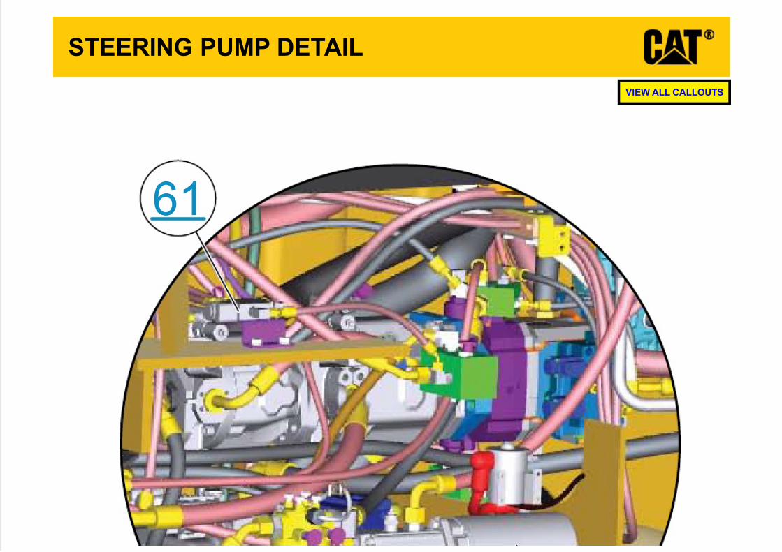
(61)VALVE GPDUALMODESTEERING
(49)SENSORGP-PRESSPRIMARYSTEERING
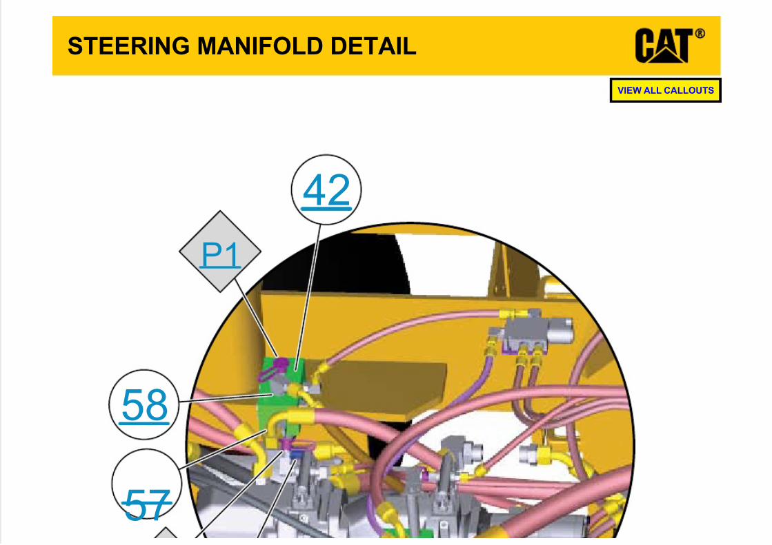
(57)VALVE AS -CHECKSTEERING INLET (58)VALVE GP-CHECK
SECONDARYSTEERING
(42)MANIFOLDGPSTEERING
(39)CYLINDERGP -STEERING
(43)ORIFICE GP RIDE CONTROLPC
(63)VALVE GPRIDE CONTROL
(57)VALVE GP-CHECKRIDE CONTROLSUPPLY
(38)CYLGP- LIFT
(40)CYLGP- TILT
(31)ACCUMULATORGPPILOT
(55)VALVE GP-BALLDEADENGINE LOWER
(37)CYLGP-HIGHLIFT TILT
(45)PUMPGP -HAND METERING UNIT(W/DUALMODE STEERING)
(47)PUMPGPSECONDARYSTEERING
(W/ INTEGRATEDRELIEF)
P6
P3
P5
P1
P2P4
P18
(39)CYLINDERGPSTEERING
P1
(58)VALVE GP-CHECKSECONDARYSTEERING
(44)PUMPGP -HAND METERING UNIT
P4 P2
(65)PUMPGPIMPLEMENT
(66)PUMPGP
STEERING
7/23/2019 Uenr4713uenr4713 Sis
http://slidepdf.com/reader/full/uenr4713uenr4713-sis 9/17
STEERING PUMP DETAIL
61
VIEW ALL CALLOUTS
7/23/2019 Uenr4713uenr4713 Sis
http://slidepdf.com/reader/full/uenr4713uenr4713-sis 10/17
STEERING MANIFOLD DETAIL
P1
58
57
42
VIEW ALL CALLOUTS
7/23/2019 Uenr4713uenr4713 Sis
http://slidepdf.com/reader/full/uenr4713uenr4713-sis 11/17
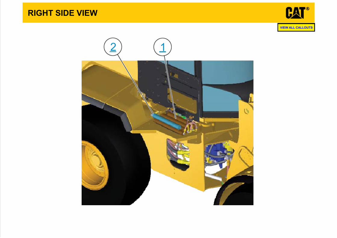
RIGHT SIDE VIEW
2 1
VIEW ALL CALLOUTS
7/23/2019 Uenr4713uenr4713 Sis
http://slidepdf.com/reader/full/uenr4713uenr4713-sis 12/17
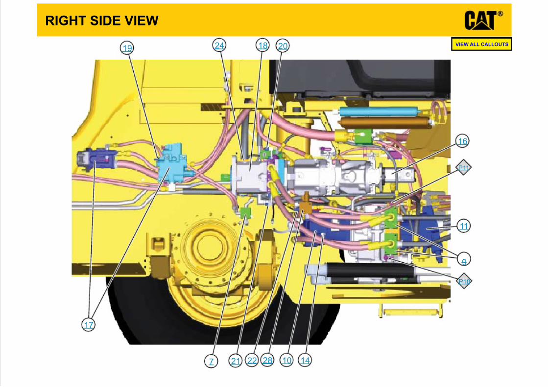
RIGHT SIDE VIEW
P11
P10
28
24
2221
2019 18
17
16
14
11
10
9
7
VIEW ALL CALLOUTS
7/23/2019 Uenr4713uenr4713 Sis
http://slidepdf.com/reader/full/uenr4713uenr4713-sis 13/17
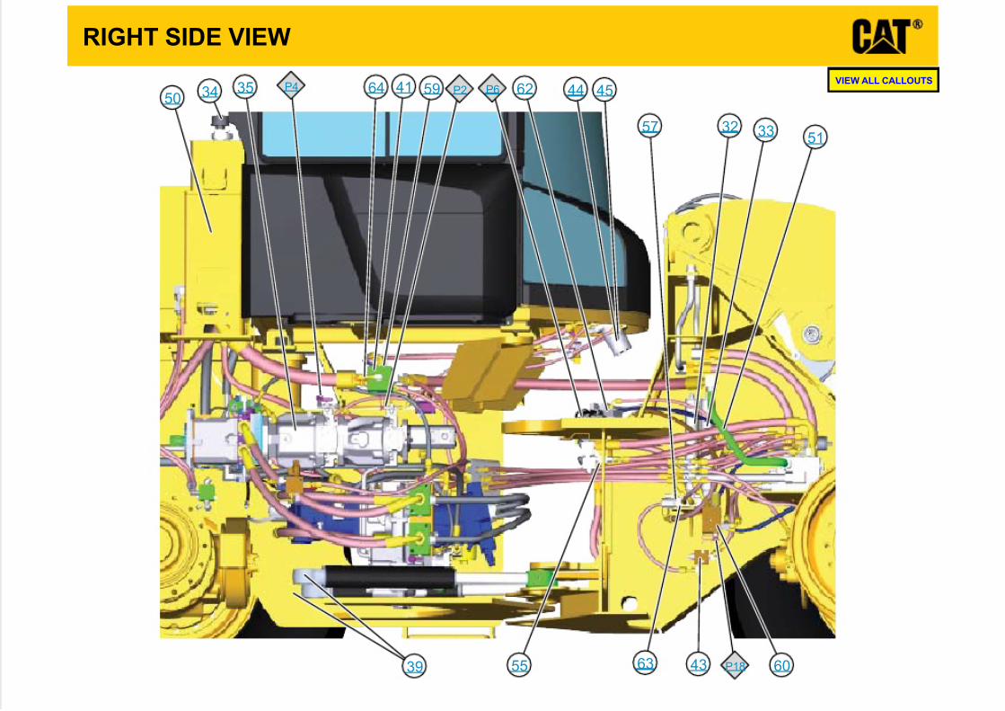
RIGHT SIDE VIEW
P18
P6P4 P264
63
62
60
59
57
55
51
50 4544
43
41
39
3534
3332
VIEW ALL CALLOUTS
7/23/2019 Uenr4713uenr4713 Sis
http://slidepdf.com/reader/full/uenr4713uenr4713-sis 14/17
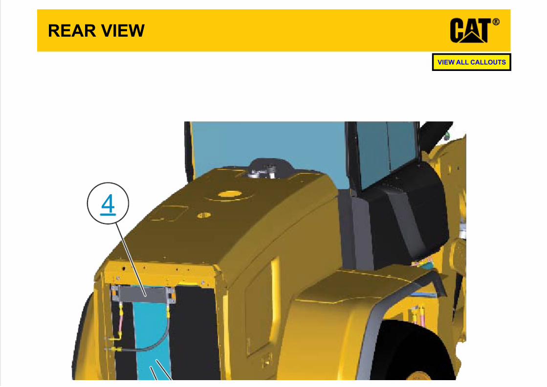
REAR VIEW
4
VIEW ALL CALLOUTS
7/23/2019 Uenr4713uenr4713 Sis
http://slidepdf.com/reader/full/uenr4713uenr4713-sis 15/17
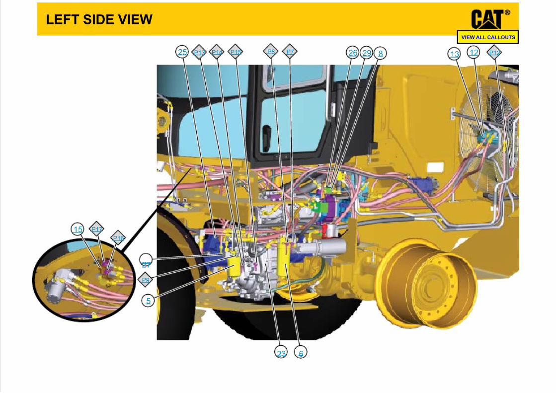
LEFT SIDE VIEW
P17
P16
P15P14P13 P12
P9
P8 P7 29
27
2625
23
15
13 128
6
5
VIEW ALL CALLOUTS
7/23/2019 Uenr4713uenr4713 Sis
http://slidepdf.com/reader/full/uenr4713uenr4713-sis 16/17
FRONT VIEW
P5
P3
56545352
48
36
31
VIEW ALL CALLOUTS
7/23/2019 Uenr4713uenr4713 Sis
http://slidepdf.com/reader/full/uenr4713uenr4713-sis 17/17
FRONT CYLINDERS
40
38
3735
VIEW ALL CALLOUTS