Embed Size (px)
Citation preview

8/12/2019 Uec 3 & Uec3 Mpc Manual440-12100
http://slidepdf.com/reader/full/uec-3-uec3-mpc-manual440-12100 1/40
UEC-3 &UEC-3-MPC
Bulletin 440-12100 6/96
Installation & Commissioning Manual
Limitorque ®

8/12/2019 Uec 3 & Uec3 Mpc Manual440-12100
http://slidepdf.com/reader/full/uec-3-uec3-mpc-manual440-12100 2/40
UEC-3 & UEC-3-MPC Installation & Commissioning Manual ©1996 Copyright Limitorque Corporation, All rights reserved.
Printed in the United States of America.
Disclaimer
All rights reserved. No part of this book shall be reproduced, stored in a retrievalsystem, or transmitted by any means, electronic, mechanical, photocopying,
recording, or otherwise without the written permission from Limitorque.While
every precaution has been taken in the preparation of the book, the publisher
assumes no responsibility for errors or omissions. Neither is any liability
assumed for damages resulting from the use of the information contained
herein.
This document is proprietary information of Limitorque Corporation furnished
for customer use ONLY. No other uses are authorized without written permis-
sion of Limitorque Corporation.
Limitorque Corporation reserves the right to make changes, without notice, tothis document and the products it describes. Limitorque Corporation shall not
be liable for technical or editorial errors or omissions made herein; nor for inci-
dental or consequential damages resulting from the furnishing, performance
or use of this document.
This manual contains information that is correct to the best of Limitorque’s
knowledge. It is intended to be a guide and should not be considered as a sole
source of technical instruction, replacing good technical judgment, since all
possible situations cannot be anticipated. If there is any doubt as to exact
installation, configuration, and/or use, call Limitorque Corporation‚ at (804)
528-4400.
The choice of system components is the responsibility of the buyer, and the
use to which they are put cannot be the liability of Limitorque Corporation.
However, Limitorque’s sales team and application engineers are always avail-
able to assist you in making your decision.
AcknowledgmentsSections of this document are edited and/or reprinted with the written per-
mission of A.E.G. Modicon Inc and Allen-Bradley‚ a Rockwell International
Company.
LOGITORQUE® and LIMITORQUE® are registered trademarks of Limitorque Corporation
Modbus® is a registered trademarks of A.E.G. Modicon, Inc
BITBUS® is a registered trademark of Intel Corporation
MS-DOS® is a registered trademark of Microsoft Corporation
IBM-PC is a registered trademark of International Business Machines Corporation
Belden® is a registered trademark of Belden, a division of Cooper Industries, Inc.
Limitorque Corporation UEC-3 & UEC-3-MPC Installation & Commissioning Manual
Bulletin 440-12100 6/96
i

8/12/2019 Uec 3 & Uec3 Mpc Manual440-12100
http://slidepdf.com/reader/full/uec-3-uec3-mpc-manual440-12100 3/40
Contents
1. Introduction 1
1.1 Premise............................................................................................................................................11.2 Emphasis .........................................................................................................................................1
1.3 Audience ..........................................................................................................................................2
2. Product Description 32.1 UEC-3...............................................................................................................................................3
2.2 UEC-3-MPC.....................................................................................................................................3
3. General Information/Workmanship 53.1 Safety Information............................................................................................................................5
3.2 Electrostatic Discharge Awareness................................................................................................5
3.3 UEC-3 Label ....................................................................................................................................6
3.4 Dip Switch Location and Conventions ...........................................................................................73.5 EPROM Care and Installation ........................................................................................................9
3.5.1 Care and Storage...........................................................................................................9
3.5.2 Removal........................................................................................................................10
3.5.3 Installation.....................................................................................................................10
3.6 Supply Voltage...............................................................................................................................10
4. UEC-3/UEC-3-MPC Installation 134.1 Site preparation .............................................................................................................................13
4.2 Visual inspection ...........................................................................................................................13
4.3 Wire preparation............................................................................................................................13
4.4 Actuator Wiring ..............................................................................................................................13
4.5 Grounding ......................................................................................................................................14
5. UEC-3/UEC-3-MPC Commissioning 155.1 Initial inspection .............................................................................................................................15
5.2 Start-up procedure ........................................................................................................................15
5.2.1 Power LEDs .................................................................................................................17
5.2.2 Reset LEDs..................................................................................................................17
5.3 UEC-3-MPC Calibration Procedure .............................................................................................18
5.4 Troubleshooting..............................................................................................................................23
5.4.1 Troubleshooting Tools ..................................................................................................23
5.4.1.1 Universal Diagnostic Tool...........................................................................23
5.4.1.2 Modsim Diagnostic Software.....................................................................23
5.4.2 Component Replacement ...........................................................................................24
5.4.2.1 Control Fuse Replacement........................................................................24
5.4.2.2 24VDC I/O Power Supply Fuse Replacement ........................................25
Limitorque Corporation UEC-3 & UEC-3-MPC Installation & Commissioning Manua
Bulletin 440-12100 6/96

8/12/2019 Uec 3 & Uec3 Mpc Manual440-12100
http://slidepdf.com/reader/full/uec-3-uec3-mpc-manual440-12100 4/40
5.4.2.3 Single Board Computer Replacement......................................................26
5.4.2.4 Termination/Interconnect Board Replacement .........................................27
5.4.3 Complete Module Replacement .................................................................................28
6. Conversion of UEC-3 Basic Controller 31
6.1 Converting UEC-3 to UEC-3-MPC Position Controller...............................................................316.1.1 Installation of PT20SD (optional) ................................................................................32
7. Parts 33
8. Customer Service 35
Figures3-1 Model, Option, and Configuration Identification Label..................................................................6
3-2 Single Board Computer DIP Switch and Component Location ...................................................7
3-3 DIP Switch Conventions .................................................................................................................8
3-4 Default DIP Switch Settings for UEC-3 and UEC-3-MPC ............................................................93-5 Locating Power Supply Board .....................................................................................................11
3-6 Locating Power Supply Board Mounting Screw..........................................................................11
3-7 Locating Power Supply Bracket Retaining Screw.......................................................................12
3-8 Power Supply Board .....................................................................................................................12
5-1 UEC-3/UEC-3-MPC Start-up Procedure.....................................................................................16
5-2 UEC-3-MPC Calibration Procedure........................................................................................18-21
Tables5-1 Table of Values for Proportional Band and Deadband................................................................22
Limitorque Corporation UEC-3 & UEC-3-MPC Installation & Commissioning Manual
Bulletin 440-12100 6/96
iii

8/12/2019 Uec 3 & Uec3 Mpc Manual440-12100
http://slidepdf.com/reader/full/uec-3-uec3-mpc-manual440-12100 5/40
1. Introduction
1.1 Premise
These instructions are to aid in the installation and commissioning of the UEC-
3 family of control modules. Your safety and satisfaction are important to
Limitorque. Be sure to follow all instructions carefully. Pay special attention to
safety.
1.2 Emphasis
Please refer to the following methods used to emphasize text throughout this
manual:
• Safety warnings, cautions, and notes present material that is important to
user safety. Be sure to read any safety notices you see as they could preventequipment damage, personal injury, or even death to you or a co-worker.
• “Warning” refers to personal safety. They alert you to potential danger or
harm. Failure to follow warning notices could result in personal injury or death.
• “Caution” directs attention to general precautions, which if not followed, could
result in personal injury and/or equipment damage.
• “Note” highlights information critical to your understanding or use of these
products.
• Bold text highlights other important information that is critical to system com-
ponents.
• CAPITALIZED text stresses attention to the details of the procedure.
• Underlined text emphasizes crucial words in sentences that could be mis-
understood if the word is not recognized.
The purpose of this section is to alert you to possible safety hazards associ-
ated with this equipment and the precautions you can take to reduce the risk
of personal injury and damage to the equipment.
Safety notices in this manual provide important information. Read and be famil-
iar with these instructions before attempting installation, operation, or
maintenance. Failure to observe these precautions could result in serious
bodily injury, damage to the equipment, or operational difficulty.
Limitorque Corporation UEC-3 & UEC-3-MPC Installation & Commissioning Manua
Bulletin 440-12100 6/96

8/12/2019 Uec 3 & Uec3 Mpc Manual440-12100
http://slidepdf.com/reader/full/uec-3-uec3-mpc-manual440-12100 6/40
1.3 Audience
This Installation and Commissioning Manual is designed to help you to prop-
erly install and commission the UEC-3 Control Module and the UEC-3
Modulating Position Controller.You do not have to be an expert in electronics
or digital controls to utilize this manual. However, this manual assumes youhave a working understanding of basic electronics and a fundamental under-
standing of microprocessor concepts.
The material in this manual supplements the following Limitorque publication:
UEC-3 Operation Manual - Bulletin 440-12000 Rev. A.
It is recommended that you completely read all the general information and
all sections pertaining to the type of UEC-3 module for your application so that
you can promptly find any information you need.
It is also recommended that you have a copy of the Operation Manual for your
UEC-3 module as well as the applicable actuator wiring diagram availablebefore attempting to install or commission a UEC-3 or UEC-3-MPC controlled
actuator.
Limitorque Corporation UEC-3 & UEC-3-MPC Installation & Commissioning Manual
Bulletin 440-12100 6/96
2

8/12/2019 Uec 3 & Uec3 Mpc Manual440-12100
http://slidepdf.com/reader/full/uec-3-uec3-mpc-manual440-12100 7/40
2. Product Description
The UEC-3 is a microprocessor based controller for the complete range of
Limitorque actuators. It provides many protection and control features whichare designed to be individually configured to fit specific customer needs.This
configuration may be altered in the field as process requirements change or
as the real needs of the actuator are realized.
2.1 UEC-3
(Universal Electronic Controller)
The basic UEC-3 model provides control, indication, alarm, and protection
features. It is intended for use with open/close or pushbutton throttling valves.
2.2 UEC-3-MPC(Modulating Position Controller)
This model is designed to position valves in accordance with a 4-20mA
command signal, thereby controlling level, flow, pressure, etc. All the indica-
tion, alarm, and protection features of the basic UEC-3 are retained in this
model.
Limitorque Corporation UEC-3 & UEC-3-MPC Installation & Commissioning Manua
Bulletin 440-12100 6/96

8/12/2019 Uec 3 & Uec3 Mpc Manual440-12100
http://slidepdf.com/reader/full/uec-3-uec3-mpc-manual440-12100 8/40
This page is intentionally blank.
Limitorque Corporation UEC-3 & UEC-3-MPC Installation & Commissioning Manual
Bulletin 440-12100 6/96
4

8/12/2019 Uec 3 & Uec3 Mpc Manual440-12100
http://slidepdf.com/reader/full/uec-3-uec3-mpc-manual440-12100 9/40
3. General Information/Workmanship
Throughout this manual, the designation “UEC-3” will refer to a basic Universal
Electronic Controller with a 4-wire configuration. UEC-3-MPC will refer to theUniversal Electronic Controller with positioning control.
The information in this section is applicable to all members of the UEC-3 family
of controllers.
3.1 Safety Information
Practice all plant and safety codes and standards. Failure to follow instructions
can result in personal injury and/or property damage.
To prevent the possible ignition of hazardous atmospheres, do NOT remove
the cover of Division 1 units with power applied.
All servicing should be performed by qualified technicians. Dangerous volt-
ages may be present on the circuit boards and terminations.
Use extreme caution when working around power-input cables.These cables
have potentially lethal voltages on them.
When fuse replacement is required, use only Limitorque specified parts for
continued safe operation.
Have qualified personnel verify all wiring and connections against vendor draw-
ings prior to energizing the equipment. Incorrect wiring and/or connections
can result in equipment damage.
3.2 Electrostatic Discharge Awareness
The circuit boards in the UEC products may contain components that are
subject to damage from electrostatic discharge (static electricity).The follow-
ing precautions and procedures are recommended when handling circuit
boards or components.Failure to observe these practices when handling and
shipping circuit board products may void your warranty.
Keep plastics and other materials prone to the buildup of electrostatic charges
(static electricity) away from boards, components, and work area.
Avoid synthetic or wool clothing and wear cotton or cotton blend materials.
Keep components and circuit boards away from clothing and hair.
Discharge static electricity on your body by touching and momentarily holding
a grounded metal object before handling electronic components.This is espe-
Limitorque Corporation UEC-3 & UEC-3-MPC Installation & Commissioning Manua
Bulletin 440-12100 6/96

8/12/2019 Uec 3 & Uec3 Mpc Manual440-12100
http://slidepdf.com/reader/full/uec-3-uec3-mpc-manual440-12100 10/40
cially important after walking across carpeted areas.
Handle components in the field as little as necessary.
Handle components only by the edges, and avoid contact with leads, circuits,
or connectors.
Do not touch the printed circuit board, the connectors, or the components with
conductive devices or with your hands.
Always place the component or board into an anti-static protective bag for
transportation or storage.
Transport all static-sensitive components only in static-shielding carriers or
packages. Place static awareness labels on all components to prevent removal
from static-shielding container during transit.
Handle all static-sensitive components at a static-safe work area including:floor mat, wrist strap, air ionizer, ground cord, and conductive table mat.
Do not subject components to sliding movements over any surface, at any
time.
3.3 UEC-3 Labels
Labels are affixed to the housings of all UEC modules.The information included
on this label indicates: type of UEC-3 (basic, MPC or DDC), options, trans-
former voltage, module serial number and status of LK1 link. The label also
contains space for the user to record the settings of the configuration DIP
switches. See Figure 3-1
Figure 3-1 - Model, Option, and Configuration Identification Label
Limitorque Corporation UEC-3 & UEC-3-MPC Installation & Commissioning Manual
Bulletin 440-12100 6/96
6
S2
S3
S1
1 2 3 4 5 6 7 8
1 2 3 4 5 6 7 8
1 2 3 4
ON
OFF
ON
OFF
ON
OFF(DDC Only)
OUTINLK1:
UEC-3 BASIC CONFIGURATION
SWITCH POSITIONS
Serial No.
Model Options
UEC-3 BASIC
UEC-3-MPC
Potentiometer
PT20S (R-1)
LogitorqueUEC-3-DDC
Type A
Transformer Type/Tapping
Type B
4 6 0 V
4 1 5 V
3 8 0 V
2 2 0 V
5 7 5 V
5 2 5 V
2 2 0 V
1 1 5 V
8/12/2019 Uec 3 & Uec3 Mpc Manual440-12100
http://slidepdf.com/reader/full/uec-3-uec3-mpc-manual440-12100 11/40
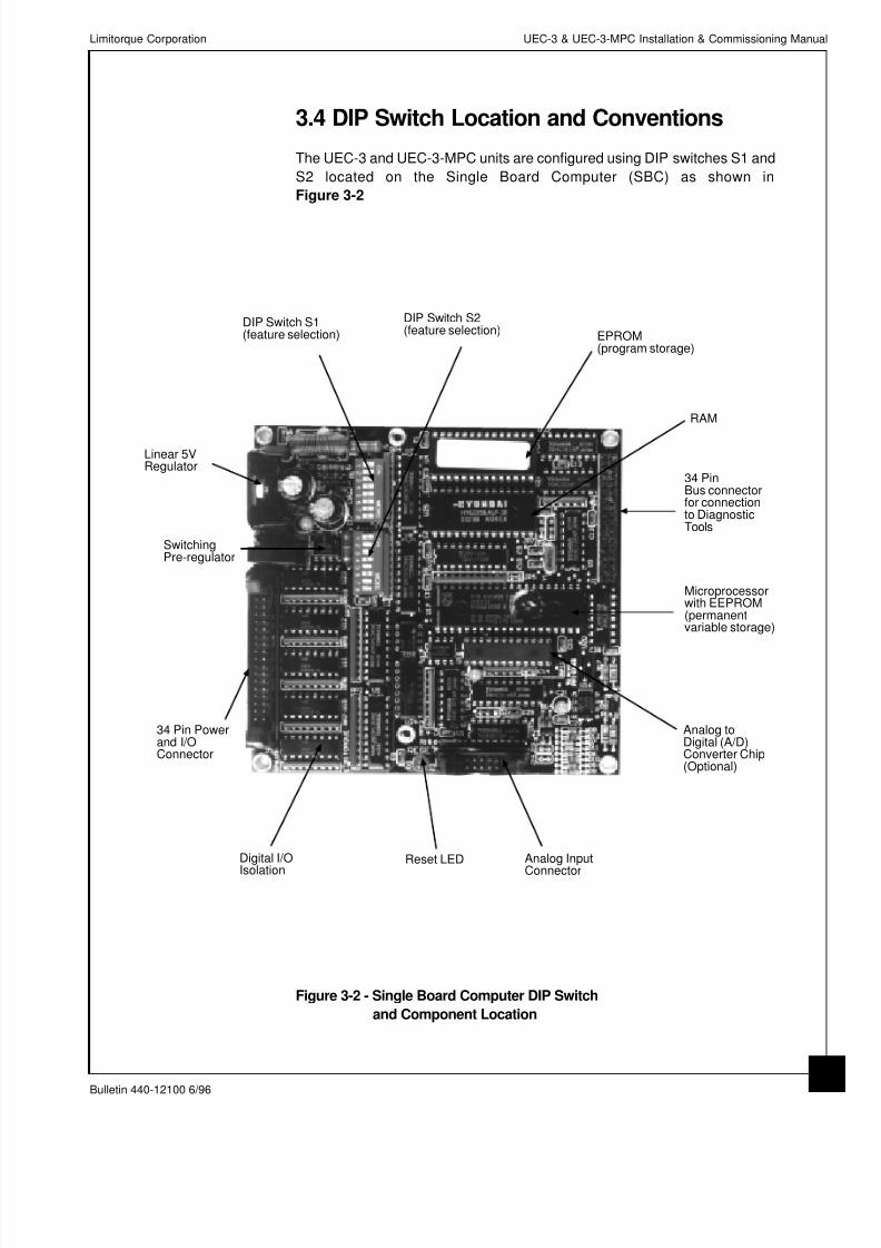
3.4 DIP Switch Location and Conventions
The UEC-3 and UEC-3-MPC units are configured using DIP switches S1 and
S2 located on the Single Board Computer (SBC) as shown in
Figure 3-2
Limitorque Corporation UEC-3 & UEC-3-MPC Installation & Commissioning Manua
Bulletin 440-12100 6/96
Figure 3-2 - Single Board Computer DIP Switch
and Component Location
RAM
34 PinBus connectorfor connectionto DiagnosticTools
EPROM(program storage)
Microprocessorwith EEPROM(permanentvariable storage)
Analog toDigital (A/D)Converter Chip(Optional)
Analog Input
Connector
Reset LEDDigital I/O
Isolation
34 Pin Powerand I/OConnector
SwitchingPre-regulator
Linear 5VRegulator
DIP Switch S1(feature selection)
DIP Switch S2(feature selection)

8/12/2019 Uec 3 & Uec3 Mpc Manual440-12100
http://slidepdf.com/reader/full/uec-3-uec3-mpc-manual440-12100 12/40
Figure 3-3 shows an example of a DIP switch and the conventions that are
used in describing the configuration of the DIP switches. An individual switch
position is said to be ON when the switch is in the CLOSED state. In the ON
position, the switch is towards the ON indication on the switch housing and
away from the number designation. All tables showing DIP switch configura-
tions indicate a “1” when the switch state is ON.
Conversely, the switch position is said to be OFF when the switch is in the
OPEN state. In the OFF position, the switch is towards the number designa-
tion and away from the ON indication on the switch housing.The tables indicate
a “0” when the switch is OFF or OPEN.
Care should be taken to assure that the each DIP switch is pushed firmly in
either the open or closed direction.
Figure 3-3 - DIP Switch Conventions
CautionAlways use a small non-metallic tool to move the DIP switches.
NEVER use a pencil because graphite filings may cause short
circuits on the printed circuit boards or in the switches.
NoteIf changes to the DIP switches are made while power is present at
the actuator, it is important to turn the power off and on again in order
to initialize the changes.
To change DIP switch settings for a particular application, refer to the UEC-3
Operation Manual Bulletin# 440-12000 Rev. A.
Limitorque Corporation UEC-3 & UEC-3-MPC Installation & Commissioning Manual
Bulletin 440-12100 6/96
8
1 2 3 4 5 6 7 8OFF
ON
Dip Swich
SX-7 Position 7

8/12/2019 Uec 3 & Uec3 Mpc Manual440-12100
http://slidepdf.com/reader/full/uec-3-uec3-mpc-manual440-12100 13/40
If sufficient information is provided at the time of order, the DIP switches will
be set according to the order. If the specific details are not provided at time of
order, the actuator will be provided with the default settings shown in
Figure 3-4.
‘ESD’ action - ‘CLOSE’ - S1-1,-2 Remote control mode - 4 WIRE - S2-1,-2-3
Local inching - DISABLED - S1-3 Seating method at ‘close’ - POSITION - S2-4Modulating mode - DISABLED - S1-4 Autophase control - ENABLED - S2-5
Slow speed opening - DISABLED - S1-5 Slow speed closing - DISABLED - S2-6
Closing rotation - CLOCKWISE - S1-6
Thermostat bypass - DISABLED - S1-7 NOTE: FOR A STANDARD UEC-3
Interlock / Inhibit - DISABLED - S1-8 ALWAYS SELECT:
EEPROM - DISABLED - S2-7
Software Control - ENABLED - S2-8
Figure 3-4 - Default DIP Switch Settings for UEC-3 and UEC-3-MPC
3.5 EPROM Care and InstallationNormally you will not need to handle the EPROM. However, if you do
need to handle the EPROM, (for example, to install a firmware upgrade),
you should follow these instructions.
3.5.1 EPROM Care and StorageThe UEC-3 family of control modules are equipped with EPROM integrated
circuits (IC) which are fragile and static sensitive. Care should be taken in the
storage and handling of the EPROMs.
Do not ship or store EPROMs near strong electrostatic, electromagnetic, mag-
netic or radioactive fields.
Do not remove labels from EPROMs.
Store EPROMs away from direct sunlight at temperatures from -40°C to
85°C (-40°F to 185°F).
Store EPROMs in static free containers with care to prevent breakage from
shock or damage to pins.
Limitorque Corporation UEC-3 & UEC-3-MPC Installation & Commissioning Manua
Bulletin 440-12100 6/96
S1ON
OFF 1 2 3 4 5 6 7 8
ONOFFKEY
S2ON
OFF 1 2 3 4 5 6 7 8
8/12/2019 Uec 3 & Uec3 Mpc Manual440-12100
http://slidepdf.com/reader/full/uec-3-uec3-mpc-manual440-12100 14/40
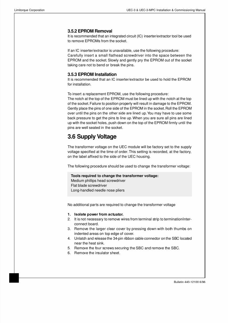
3.5.2 EPROM RemovalIt is recommended that an integrated circuit (IC) inserter/extractor tool be used
to remove EPROMs from the socket.
If an IC inserter/extractor is unavailable, use the following procedure:
Carefully insert a small flathead screwdriver into the space between theEPROM and the socket. Slowly and gently pry the EPROM out of the socket
taking care not to bend or break the pins.
3.5.3 EPROM InstallationIt is recommended that an IC inserter/extractor be used to hold the EPROM
for installation.
To insert a replacement EPROM, use the following procedure:
The notch at the top of the EPROM must be lined up with the notch at the top
of the socket.Failure to position properly will result in damage to the EPROM.
Gently place the pins of one side of the EPROM in the socket.Roll the EPROM
over until the pins on the other side are lined up.You may have to use someback pressure to get the pins to line up. When you are sure all pins are lined
up with the socket holes, push down on the top of the EPROM firmly until the
pins are well seated in the socket.
3.6 Supply Voltage
The transformer voltage on the UEC module will be factory set to the supply
voltage specified at the time of order.This setting is recorded, at the factory,
on the label affixed to the side of the UEC housing.
The following procedure should be used to change the transformer voltage:
Tools required to change the transformer voltage:
Medium phillips head screwdriver
Flat blade screwdriver
Long-handled needle nose pliers
No additional parts are required to change the transformer voltage
1. Isolate power from actuator.
2. It is not necessary to remove wires from terminal strip to termination/inter-
connect board.
3. Remove the larger clear cover by pressing down with both thumbs on
indented areas on top edge of cover.
4. Unlatch and release the 34-pin ribbon cable connector on the SBC located
near the heat sink.
5. Remove the four screws securing the SBC and remove the SBC.
6. Remove the insulator sheet.
Limitorque Corporation UEC-3 & UEC-3-MPC Installation & Commissioning Manual
Bulletin 440-12100 6/96
10

8/12/2019 Uec 3 & Uec3 Mpc Manual440-12100
http://slidepdf.com/reader/full/uec-3-uec3-mpc-manual440-12100 15/40
Limitorque Corporation UEC-3 & UEC-3-MPC Installation & Commissioning Manua
Bulletin 440-12100 6/96
1
Figure 3-5
Locating Power Supply Board
Figure 3-6
Locating Power Supply Board
Mounting Screw
7. Unlatch and release the 50 pin connector located on the Power Supply
Board between the fuse cartridge and the phase LEDs. Move this ribbon
cable over the edge of the enclosure to permit access to the metal plate.
8. Remove the four screws securing the metal plate. Insert a flat blade screw-
driver under the plate and gently lift and set aside. This plate will be
connected to the assembly via a green ground wire. It is not necessary toremove the ground wire from the plate.
9. Locate the Power Supply Board which is mounted on the wall of the enclo-
sure opposite the Termination/Interconnect board. See Figure 3-5.
10. Remove and retain the single screw from the outside of housing which
secures the power board from the bottom. See Figure 3-6.
11. Using a long phillips head screwdriver, partially unscrew the screw located
on the inside base of the UEC housing which holds the bracket to the
housing. See Figure 3-7. Unscrew only enough to separate the bracket
from the housing. DO NOT COMPLETELY REMOVE THIS SCREW.
12. Slide the power board slowly up and out of the housing being careful to
move wiring aside. Care should be taken to prevent damage to the wiring
insulation by coming into contact with the edges of the bracket. It is onlynecessary that the power board be moved enough to locate and change
the transformer jumpers.
(continued on next page)
Termination/
Interconnect Board
Power Supply Board
Power Supply
Board Mounting Screw

8/12/2019 Uec 3 & Uec3 Mpc Manual440-12100
http://slidepdf.com/reader/full/uec-3-uec3-mpc-manual440-12100 16/40
13. Locate the transformer jumpers as shown in Figure 3-8.
14. Using pliers, carefully remove the jumper and reinsert into position for the
desired input voltage:
Std. Optional
LK1 for 460V 575V
LK2 for 415V 525VLK3 for 380V 220V
LK4 for 220V 115
15. If the main power is single phase, set all three LK7 jumpers (located beside
the ribbon cable connector) to the 1 phase setting to disable phase detection.
16. Carefully slide the power board back into the housing.
17. Tighten the bracket screw at the base of the housing.
18. Replace and tighten the screw on the outside of the housing.
19. Replace the metal plate and secure with 4 screws.
20. Reconnect the 50-pin ribbon connector.
21. Replace the insulator sheet on top of the ribbon cable keeping the 34-pin
connector free.
22. Reconnect 34-pin connector into the SBC.23. Replace the SBC and secure with 4 screws.
24. Replace the UEC clear cover.
25. It is recommended that the new voltage with date changed be recorded
and initialed on the label located on the side of the UEC housing.
Limitorque Corporation UEC-3 & UEC-3-MPC Installation & Commissioning Manual
Bulletin 440-12100 6/96
12
Figure 3-7 -
Locating Power Supply
Bracket Retaining Screw
Figure 3-8 -
Power Supply Board
Power Supply
Bracket
Retaining
Screw
Transformer
Jumpers
LK7 - Phase
Detector
Jumpers

8/12/2019 Uec 3 & Uec3 Mpc Manual440-12100
http://slidepdf.com/reader/full/uec-3-uec3-mpc-manual440-12100 17/40
4. UEC-3/UEC-3-MPC Installation
4.1 Site Preparation
Proper site preparation is essential to the successful operation of the UEC-3
controlled actuators.
1. A site map or detailed site plan should be available.This should include
location and tag numbers of all actuators, junction boxes and terminal
strips.
2. Free access to the control compartments of each actuator will be required
for set-up, configuration and troubleshooting.
3. All wires should be properly labeled or identified.
4. Control and power wiring for the actuator should both be installed in proper
conduit but never in the same conduit.Shielding is not enough to prevent
induction of stray voltages onto signal leads from power lines.5. Power distribution grid should be available to identify the impact of power
isolation to a particular actuator or group of actuators.
4.2 Visual Inspection
The UEC module contained in your Limitorque actuator has been tested prior
to shipment. It is recommended that a visual check of the module take place
prior to applying power to the actuator.
• Check for any physical damage to the UEC module
• Verify that all ribbon cables are fully seated and that the clips are in a verti-
cal position.
• Verify that all EPROMs are properly aligned and fully seated.
4.3 Wire Preparation
For connections to the Termination/Interconnect Board, an 18 gage, 380V wire
is recommended. All wires should be stripped 0.25 inch (6 mm) from the end
and tinned with resin core solder for best results.
4.4 Actuator Wiring
It is essential that all wir ing is in accordance with the wiring diagram provided
with your actuators. Copies of the wiring diagram are mailed to purchasers of
Limitorque actuators and one copy is normally placed inside the actuator’s
control compartment before shipment. Becoming familiar with the wiring
diagram will ease setup.
Wiring Verification should be done with the actuator isolated from power.
Limitorque Corporation UEC-3 & UEC-3-MPC Installation & Commissioning Manua
Bulletin 440-12100 6/96
1

8/12/2019 Uec 3 & Uec3 Mpc Manual440-12100
http://slidepdf.com/reader/full/uec-3-uec3-mpc-manual440-12100 18/40
Note:The transformer voltage on the UEC module will be factory set to suit
the supply voltage specified at the time of order. This setting is
recorded, at the factory, on the label affixed to the side of the UEC
housing.
1. Check to make sure that the transformer voltage on the UEC-3 label is
the same as the incoming supply. If not, refer to Section 2.6 -Supply
Voltage for the procedure to change the voltage.
2 Verify that actuator wiring is in accordance with the wiring diagram shipped
with the actuator.
3. If the external control voltage is above 90VAC or 90VDC, link LK1 must be
removed. Locate LK1 at the bottom of the Termination/Interconnect Board
near the SBC. To remove, grasp the black housing and pull straight up.
4. Verify that DIP switch settings on the SBC are correct to enable the desired
functionality. See Section 2-3 of this manual for DIP switch key and basicsettings.
The unit is now ready for commissioning. See Section 5 for instructions.
4.5 Grounding
The remote control inputs on the Termination/Interconnect Board are opto-iso-
lated to protect the internal logic circuits from high voltage transients and
ground loops. Additional grounding for these inputs is not required.
Please refer to the wiring diagram for your particular Limitorque actuator for
additional grounding requirements.
Limitorque Corporation UEC-3 & UEC-3-MPC Installation & Commissioning Manual
Bulletin 440-12100 6/96
14

8/12/2019 Uec 3 & Uec3 Mpc Manual440-12100
http://slidepdf.com/reader/full/uec-3-uec3-mpc-manual440-12100 19/40
5. UEC-3/UEC-3-MPC Commissioning
5.1 Initial Checkout
All UEC-3 and UEC-3-MPC modules and their corresponding actuators are
tested before shipment to ensure proper operation. After assembly, the actu-
ator is cycled through normal operation, thereby assuring that the motor, wiring,
and controller are all functioning properly.
Final setup is not complete until the actuator is installed. Field setup is required.
Please use the instruction and maintenance manual appropriate for your actu-
ator to adjust the limit and torque switches.
Verify that the connectors for the r ibbon cables are properly seated and that
the clips are in closed position.
Verify that all socketed integrated circuits are properly aligned and fully seated.
Make sure that for MPC applications, the Analog to Digital Converter chip is
installed.
5.2 Start-up Procedure
The start-up procedure for the UEC-3 and UEC-3-MPC is given in the form of
a flow chart in Figure 5-1.
Note:The settings of the DIP switches S1 and S2 on the SBC Board should
be recorded before beginning any procedure.
Limitorque Corporation UEC-3 & UEC-3-MPC Installation & Commissioning Manua
Bulletin 440-12100 6/96
1

8/12/2019 Uec 3 & Uec3 Mpc Manual440-12100
http://slidepdf.com/reader/full/uec-3-uec3-mpc-manual440-12100 20/40
Figure 5-1 - UEC-3/UEC-3-MPC Start-up Procedure
Limitorque Corporation UEC-3 & UEC-3-MPC Installation & Commissioning Manual
Bulletin 440-12100 6/96
16
Do you wantphase correction?
SW2-5 on
Power off,then on
Yes
Set positionlimits
Center Potat 50% valve
position.Selector switch
to ‘Local’
No
Power offSwap incoming power leads
Power on
Yellow LED on?(Phase Rotation OK)
SW2-5 off
Power off,then on
Yes
No
Testpushbuttons
Open PB=> Open dirClose PB=> Close dir
Verify
Change position of SW1-6(Direction to close)
No
Power off,then on
Yes
Change other optionsas required in std.
configuration
Power off,then on
Wait 15 sec
SW93 LED’s on?See Section 6.4Troubleshooting
NoYes
UEC-3-MPCgo tocalibrationprocedure
UEC-3 End ofStart-up

8/12/2019 Uec 3 & Uec3 Mpc Manual440-12100
http://slidepdf.com/reader/full/uec-3-uec3-mpc-manual440-12100 21/40
5.2.1 Power LEDsDuring start-up check the LEDs on the power supply board. (See Figure 5-1
of Bulletin 440-12000 Rev. A. for the location of the LEDs.)
The Power Supply Boards on most versions of the UEC-3 and UEC-3 MPC
Modules have three LED indicators - red, yellow, and green.The state of theseindicators for various operating conditions are given below:
On units which have been configured for three phase power, both the red and
yellow LEDs should be illuminated when power is present to the actuator, and
the green indicator should not be illuminated
If the yellow LED is not illuminated, the unit is out of phase and incoming power
leads (L1 & L3) should be switched.
If the red LED is not illuminated, one of the phases is not present and incom-
ing power connections should be checked.
On units which have been configured for three phase power, all of the LEDs
should be illuminated when power is present to the actuator.
The green LED indicates that the phase detector circuit has been bypassed
and that there is no phase protection.
5.2.2 Reset LEDDuring Start-up, check the Reset LED on the Single Board Computer. (See
Figure 5-2 of Bulletin 440-12000 Rev. A. for the location of the RESET LED.)
On all UEC modules the Reset LED should be steadily illuminated when power
is present to the actuator.
If Reset LED blinks every 1.5 sec, check that EPROMs are properly seated
and that no pins are damaged or missing.
If Reset LED blinks every 11-12 seconds, check that module is not in extended
configuration mode.
See Bulletin 440-12000 Rev. A. for other faults which may cause this LED to
blink.
Limitorque Corporation UEC-3 & UEC-3-MPC Installation & Commissioning Manua
Bulletin 440-12100 6/96
1

8/12/2019 Uec 3 & Uec3 Mpc Manual440-12100
http://slidepdf.com/reader/full/uec-3-uec3-mpc-manual440-12100 22/40
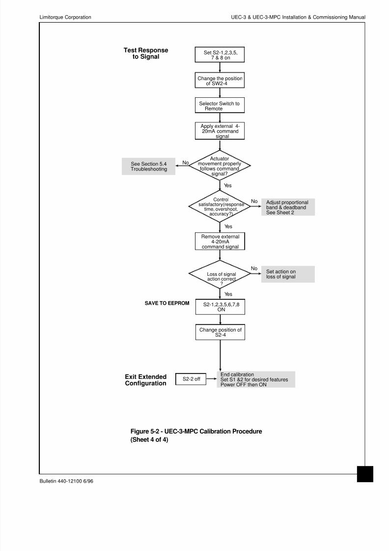
5.3 UEC-3-MPC Calibration Procedure
The calibration procedure for the UEC-3-MPC is given in the form of a flow
chart in Figure 5-2. This procedure is also discussed in the Operation Manual.
*NoteSpan and Zero reference must always be changed together
Figure 5-2 - UEC-3-MPC Calibration Procedure (Sheet 1 of 4)
Limitorque Corporation UEC-3 & UEC-3-MPC Installation & Commissioning Manual
Bulletin 440-12100 6/96
18
SW2-1,2&3 on
SW2-5,6,7 off
Selector switch
to Local
Press Open buttonWait until actuator
stops at OPEN
Set SW2-5 ON
Press Close buttonWait until actuatorstops at Closed
Set command asneeded (20mA?)
Set command asneeded (4mA?)
Change positionof SW2-4
Change position ofSW2-4
Setting Spanand Zero*
AreMPC parameters
stored?
No
YesSkip to section thatrequires adjustment
Go to Test(Sheet 3)

8/12/2019 Uec 3 & Uec3 Mpc Manual440-12100
http://slidepdf.com/reader/full/uec-3-uec3-mpc-manual440-12100 23/40
NoteThe default level for proportional band was factory set at ± 14.0%
NoteDefault level for deadband was factory set at ± 1.0%
Figure 5-2 - UEC-3-MPC Calibration Procedure (Sheet 2 of 4)
Limitorque Corporation UEC-3 & UEC-3-MPC Installation & Commissioning Manua
Bulletin 440-12100 6/96
1
Set S1 to the desiredvalue as shown onTable 5-1
Change the positionof SW2-4
Set SW2-1,2,3,6 & 8 ON
Set SW2- 5 & 7 OFF
Go to Test(Sheet 3)
Set ProportionalBand
Set S1 to the desiredvalue as shown onTable 5-1
Change the positionof SW2-4
Set SW2-1,2,3,5,6 &8ON
Set SW2- 7 OFF
Go to Test(Sheet 3)
Set Deadband

8/12/2019 Uec 3 & Uec3 Mpc Manual440-12100
http://slidepdf.com/reader/full/uec-3-uec3-mpc-manual440-12100 24/40
Figure 5-2 - UEC-3-MPC Calibration Procedure (Sheet 3 of 4)
Limitorque Corporation UEC-3 & UEC-3-MPC Installation & Commissioning Manual
Bulletin 440-12100 6/96
20
Set S1 for desiredaction.*
Change the positionof S2-4
Set S1-3,4,5,6,7,8OFF
Set S2-1,2,3,7 & 8ON
Set S2- 5 & 6OFF
Go to Test
Set Action OnLoss of Signal
*S1-1 S1-2 Act ion
OFF OFF CLOSE
ON OFF STOP
ON ON OPEN
8/12/2019 Uec 3 & Uec3 Mpc Manual440-12100
http://slidepdf.com/reader/full/uec-3-uec3-mpc-manual440-12100 25/40
Figure 5-2 - UEC-3-MPC Calibration Procedure
(Sheet 4 of 4)
Limitorque Corporation UEC-3 & UEC-3-MPC Installation & Commissioning Manua
Bulletin 440-12100 6/96
2
Set S2-1,2,3,5,7 & 8 on
Change the position of SW2-4
No
Actuatormovement properlyfollows command
signal?
See Section 6.4Troubleshooting
No
Controlsatisfactory(response
time, overshoot,accuracy?)
Yes
Yes
Apply external 4-20mA command
signal
Selector Switch to Remote
S2-1,2,3,5,6,7,8ON
Change position ofS2-4
S2-2 off
Test Responseto Signal
Exit Extended
Configuration
SAVE TO EEPROM
Remove external4-20mA
command signal
Loss of signalaction correct
?
Yes
No
See Section 5.4Troubleshooting
Adjust proportionalband & deadbandSee Sheet 2
End calibrationSet S1 &2 for desired features
Power OFF then ON
Set action onloss of signal

8/12/2019 Uec 3 & Uec3 Mpc Manual440-12100
http://slidepdf.com/reader/full/uec-3-uec3-mpc-manual440-12100 26/40
Table 5-1 - Table of Values for Proportional Band and Deadband
% DIP S1 % DIP S112345678 123456 78
1 10000000 26 01011000
2 01000000 27 11011000
3 11000000 28 00111000
4 00100000 29 10111000
5 10100000 30 01111000
6 01100000 31 11111000
7 11100000 32 00000100
8 00010000 33 10000100
9 10010000 34 01000100
10 01010000 35 11000100
11 11010000 36 00100100
12 00110000 37 10100100
13 10110000 38 01100100
14 01110000 39 11100100
15 11110000 40 00010100
16 00001000 41 10010100
17 10001000 42 01010100
18 01001000 43 11010100
19 11001000 44 00110100
20 00101000 45 10110100
21 10101000 46 01110100
22 01101000 47 11110100
23 11101000 48 00001100
24 00011000 49 10001100
25 10011000 50 01001100
Limitorque Corporation UEC-3 & UEC-3-MPC Installation & Commissioning Manual
Bulletin 440-12100 6/96
22

8/12/2019 Uec 3 & Uec3 Mpc Manual440-12100
http://slidepdf.com/reader/full/uec-3-uec3-mpc-manual440-12100 27/40
5.4 Troubleshooting
If no Pushbutton Station LEDs are illuminated, see the Troubleshooting Charts.
(See Figures 9-2, 9-3, and 9-4 of the Operation Manual.)
5.4.1 Troubleshooting ToolsLimitorque has developed diagnostic tools to aid in troubleshooting UEC-3
and UEC-3-MPC controlled actuators. The use of either of these tools will
assist in the quick diagnosis of actuator alarms and faults.
5.4.1.1 Universal Diagnostic Tool
The Universal Diagnostic Tool (UDT) is a hand held device that can determine
and diagnose the source of valve actuator alarms and faults on any UEC- 3
or UEC-3-MPC based actuator. It is designed as a first-level diagnostic tool
providing preliminary troubleshooting information and is very easy to use.
Please refer to the UEC-3 and DDC-100 Diagnostic Interface Installation and
Operation Manual - Bulletin 437-10000 for instructions on using the UDT.
5.4.1.2 Modsim Diagnostic Software
A personal computer and Modsim diagnostic software can be used to trou-
bleshoot the UEC-3 controlled actuator. Modsim is designed to provide detailed
diagnostic information in addition to the information provided by the UDT.
Please refer to the UEC-3 and DDC-100 Diagnostic Interface Installation and
Operation Manual - Bulletin 437-10000 for UEC-3 to PC connectivity.
Please refer to the Modsim Modbus Simulation Software Operation Manual -
Bulletin 435-23001 for instructions for using Modsim.
Limitorque Corporation UEC-3 & UEC-3-MPC Installation & Commissioning Manua
Bulletin 440-12100 6/96
2

8/12/2019 Uec 3 & Uec3 Mpc Manual440-12100
http://slidepdf.com/reader/full/uec-3-uec3-mpc-manual440-12100 28/40
5.4.2 Component ReplacementLimitorque recommends the field replacement of Control and I/O Power Supply
fuses, Single Board Computer, and Termination /Interconnect Board. If any
other components within the UEC-3 or UEC-3-MPC module require replace-
ment, it is recommended that the complete UEC-3 or UEC-3-MPC module be
replaced. See Section 5.4.3 for instructions on replacing the completeUEC module.
5.4.2.1 Control Fuse Replacement
The following procedure should be used to replace the 120V control power
fuse (FS3) on the Power Supply Board:
Tools required:
Small flathead screwdriver
Parts Required:
Control fuse: P/N: EF2-5X20MM-1A-250V
1. ISOLATE POWER FROM THE ACTUATOR.
2. Remove cover bolts and open control compartment cover.
3. Remove the larger clear cover of the UEC-3 by pressing down with both
thumbs on indented areas on top edge of cover.
4. Locate the fuse cartridge near the 50 pin IDC connector and the heat sink.
5. Insert screwdriver into slot on cap of fuse cartridge and turn 90°in the
direction of the arrow.
6. Lift cap with fuse out of the cartridge.
7. Pull fuse out of cap and replace with Limitorque P/N: EF2-5X20MM-1A-
250V
8. Inspect replacement fuse to confirm that it is the correct size and undam-
aged.
9. Be sure to insert replacement fuse firmly in cap.
10. Align the brackets on the cap and fuse assembly with the notch in the car-
tridge and push straight in to insert.
11. Insert screwdriver into slot on cap of fuse cartridge and turn 90°opposite
direction of ARROW.
12. Replace clear cover.
Limitorque Corporation UEC-3 & UEC-3-MPC Installation & Commissioning Manual
Bulletin 440-12100 6/96
24

8/12/2019 Uec 3 & Uec3 Mpc Manual440-12100
http://slidepdf.com/reader/full/uec-3-uec3-mpc-manual440-12100 29/40
5.4.2.2. 24 VDC I/O Power Supply Fuse Replacement
Tools required:
Small flat head screwdriver
Parts required:24VDC I/O Power Fuse P/N: EF2-5X20MM-1A-250V
1. ISOLATE POWER FROM ACTUATOR.
2. Remove cover bolts and open control compartment cover.
3. To gain access to the Termination/ Interconnect Board, remove the smaller
clear cover on the UEC-3 by inserting a flat head screwdriver in the gap
at the front of the cover and lifting up and towards the base of the housing.
4. Locate the fuse near the pushbutton station IDC connector.
5. Remove the protective shroud from the fuse by inserting the screwdriver
blade under the shroud at each end and pry gently.
6. Remove fuse by inserting the screwdriver blade under one end of the fuseand pry gently until it is free from the fuse holder.
7. Inspect the replacement fuse (Limitorque P/N: EF2-5X20MM-1A-250V)
to confirm that it is the correct size and undamaged.
8. Insert the replacement fuse by lining up the metal ends with the metal
brackets on the fuse holder and pushing the fuse straight down into the
fuse holder.
9. Replace protective shroud over the fuse and holder.To ease replacement,
squeeze the ends of the shroud gently to expand as you are replacing.
10. Replace clear plastic cover.
Limitorque Corporation UEC-3 & UEC-3-MPC Installation & Commissioning Manua
Bulletin 440-12100 6/96
2

8/12/2019 Uec 3 & Uec3 Mpc Manual440-12100
http://slidepdf.com/reader/full/uec-3-uec3-mpc-manual440-12100 30/40
5.4.2.3. Single Board Computer (SBC) Replacement
The following procedure should be used to replace the SBC:
Tools required:
Medium phillips head screwdriver
Small non-metallic tool for DIP Switch setting
Parts Required:
Single Board Computer: P/N: 61-825-0996-1
1. ISOLATE POWER FROM ACTUATOR.
2. Remove cover bolts and open control compartment cover.
3. Remove the larger clear cover of the UEC-3 by pressing down with both
thumbs on indented areas on top edge of cover.
4. Unlatch and release the 34-pin ribbon cable on the SBC located near the
heat sink.
5. Remove the four screws securing the SBC and remove the board.6. It is not necessary to replace the insulator sheet with a new sheet unless
visible damage is present.
7. Inspect replacement SBC for obvious damage and verify that the Analog
to Digital Converter (ADC) chip (if required) is installed.
NoteMake sure that Analog to Digital Converter (ADC) chip is installed
for modulating applications.
8. Connect the 34-pin connector into the replacement SBC.
9. Position replacement SBC on top of the insulator sheet and secure with
four screws.
10. Set the DIP switch on the replacement SBC to match the one being
replaced.
11. Replace the UEC-3 clear cover.
Limitorque Corporation UEC-3 & UEC-3-MPC Installation & Commissioning Manual
Bulletin 440-12100 6/96
26

8/12/2019 Uec 3 & Uec3 Mpc Manual440-12100
http://slidepdf.com/reader/full/uec-3-uec3-mpc-manual440-12100 31/40
5.4.2.4.Termination/Interconnect Board Replacement
The following procedure should be used to replace the Termination
/Interconnect Board:
Tools required:
Medium phillips head screwdriverSmall flat head screwdriver
Parts required:
Termination/Interconnect Board: P/N: TM74-743-0050
1. ISOLATE POWER FROM ACTUATOR.
2. Remove cover bolts and open control compartment cover.
3. Remove the larger clear cover of the UEC-3 by pressing down with both
thumbs on indented areas on top edge of cover.
4. Unlatch and remove the 50 pin ribbon connector located at the end of the
Termination/Interconnect Board adjacent to the SBC near the 34 pin con-nector. Return the release latches to the closed position.
5. Remove smaller clear cover by inserting a flat head screwdriver in the gap
at the bottom of the cover and lifting up and towards the base of the
housing.
6. Disconnect all incoming wires to the Termination/Interconnect Board. Make
sure all wires are labeled for easy reconnection.
7. Position latches for both IDC connectors on the Termination/ Interconnect
Board to the closed position before attempting to remove.
8. Remove and retain the 4 mounting screws on the Termination/Interconnect
Board. Pull the Termination/Interconnect Board away from the SBC to clear
the 50 pin connector to remove.
9. Inspect the replacement Termination/Interconnect Board for obvious
damage.
10. Position latches for both IDC connectors on the replacement Termination/
Interconnect Board to the closed position before attempting to install.
11. Install the replacement board by gently inserting the 50 pin connector into
the slot adjacent to SBC.The 40 pin connector will fit in the slot provided.
Secure this board with 4 mounting screws.
12. Reconnect wires to the terminals on the replacement Termination/
Interconnect Board.
13. Replace small clear cover.
14. Reconnect the 50 pin ribbon cable to the Termination/Interconnect Board.
15. Replace larger clear cover.
16. Reconnect IDC connector (J6).
Limitorque Corporation UEC-3 & UEC-3-MPC Installation & Commissioning Manua
Bulletin 440-12100 6/96
2

8/12/2019 Uec 3 & Uec3 Mpc Manual440-12100
http://slidepdf.com/reader/full/uec-3-uec3-mpc-manual440-12100 32/40
5.4.3 Complete UEC-3 or UEC-3-MPC Module ReplacementThe procedure for the replacement of the complete UEC-3 or UEC-3-MPC
module is as follows:
Tools required to replace the complete UEC-3 or UEC-3-MPC Module:
Small flat blade screwdriverMedium flat blade screwdriver
Small non-metallic DIP switch tool
Parts Required:
Replacement UEC-3 or UEC-3-MPC Module - contact your local distributor
or Limitorque Parts Department for correct P/N for your application.
1. ISOLATE POWER FROM THE ACTUATOR.
2. Remove cover bolts and open control compartment cover.
3. Disconnect leads from the UEC module at the terminal strip.
4. Disconnect ribbon cable connections to Pushbutton Station and gearedlimit switch at Termination/Interconnect Board.
5. Disconnect remaining Termination/Interconnect Board wiring to other
devices such as an R/I converter.
6. Remove and save the 4 mounting screws on the base of the UEC module
and remove the assembly.
7. Set the DIP switches on the SBC of the replacement module to match
those of the module removed.
8. Check to make sure that the transformer voltage on the replacement
module is the same as on the module removed. If not, please refer to
Section 2.6 - Supply Voltage for the procedure to change the voltage.
NoteReplacement UEC-3 and UEC-3-MPC modules are shipped with 460V
transformer voltage as standard unless otherwise specified on parts
order.
9. Mount the new UEC-3 module on the mounting plate using 4 screws.
NoteFor replacement in L-120 actuators, it is necessary that the module
be secured first by the mounting screw closest to the input wires,
followed by the screw on the opposite side of the box.These should
hold the module secure while the remaining screws are put in.
Limitorque Corporation UEC-3 & UEC-3-MPC Installation & Commissioning Manual
Bulletin 440-12100 6/96
28

8/12/2019 Uec 3 & Uec3 Mpc Manual440-12100
http://slidepdf.com/reader/full/uec-3-uec3-mpc-manual440-12100 33/40
10. Reconnect wiring and ribbon cables to the Termination/Interconnect Board.
11. Connect wires from UEC-3 module to terminal strip according to wiring
diagram supplied with actuator.
12. Reapply power to the actuator.
13. Verify proper operation. See Section 5.2.
Limitorque Corporation UEC-3 & UEC-3-MPC Installation & Commissioning Manua
Bulletin 440-12100 6/96
2

8/12/2019 Uec 3 & Uec3 Mpc Manual440-12100
http://slidepdf.com/reader/full/uec-3-uec3-mpc-manual440-12100 34/40
This page is intentionally blank.
Limitorque Corporation UEC-3 & UEC-3-MPC Installation & Commissioning Manual
Bulletin 440-12100 6/96
30

8/12/2019 Uec 3 & Uec3 Mpc Manual440-12100
http://slidepdf.com/reader/full/uec-3-uec3-mpc-manual440-12100 35/40
6. Conversion of the UEC-3Basic Controller
An installed UEC-3 control module can be modified in the field to operate asa UEC-3-MPC controller.These changes should be performed by a qualified
technician using genuine Limitorque parts and following the procedures in this
section. All tools and parts required are listed in each procedure.
6.1 Converting UEC-3 to
UEC-3-MPC Position Controller
The UEC-3-MPC is a 4-20 milliAmp controller which will change the position
of the valve in proportion to a current signal received from a set point con-
troller or similar device.
An actuator originally supplied with UEC-3 controls may be changed to UEC-
3-MPC controlled actuator.
The following procedures should be used to convert a UEC-3 actuator to a
UEC-3-MPC actuator:
Tools required:
Small non-metallic DIP switch tool
Small flat blade screwdriver
Medium flat blade screwdriver
Parts required:
Feedback potentiometer: Consult factory for part required
Analog Interface Board: P/N: 61-825-0962-2
A/D Converter Chip: P/N: 61-825-0733-1
Optional UEC-3-MPC parts:
PT20SD Position Transmitter: P/N: TM74-743-0066
1. ISOLATE POWER FROM THE ACTUATOR.
2. Remove actuator cover bolts and open control compartment cover.
3. Install potentiometer if not already installed in actuator. See actuator
Instruction and Maintenance manual for installation instructions or contact
your local Limitorque distributor for information.
4. Install Analog Interface Board. Analog board installation differs with type
and size of actuator. Consult factory or nearest service center for instal-
lation instructions.
Limitorque Corporation UEC-3 & UEC-3-MPC Installation & Commissioning Manua
Bulletin 440-12100 6/96
3

8/12/2019 Uec 3 & Uec3 Mpc Manual440-12100
http://slidepdf.com/reader/full/uec-3-uec3-mpc-manual440-12100 36/40
5. Remove the large clear cover on the UEC-3 module and connect ribbon
cable, J3A, from the Analog Interface Board to J3 connector on the Single
Board Computer (SBC).When the cover is replaced, the ribbon cable will
fit through the cut-out in the cover.
6. Before replacing the cover, install the Analog to Digital Converter chip into
U18 on the Single Board Computer being careful to match notches andavoid bending pins.The location of the Analog to Digital Converter (U18)
is shown in Figure 5-2 of the Operation Manual.
7. Calibrate the UEC-3-MPC (See UEC-3 Operation Manual - Bulletin 440-
12000 Rev. A., and Section 5.3 of this manual for calibration procedure).
6.1.1 Installation of the PT20SD (Optional)The procedure and parts required for the installation of PT20SD differs accord-
ing to the type and size of Limitorque actuator. Please consult the nearest
Limitorque Blue Ribbon Service facility or Limitorque’s Service Department
for assistance.
Limitorque Corporation UEC-3 & UEC-3-MPC Installation & Commissioning Manual
Bulletin 440-12100 6/96
32
8/12/2019 Uec 3 & Uec3 Mpc Manual440-12100
http://slidepdf.com/reader/full/uec-3-uec3-mpc-manual440-12100 37/40
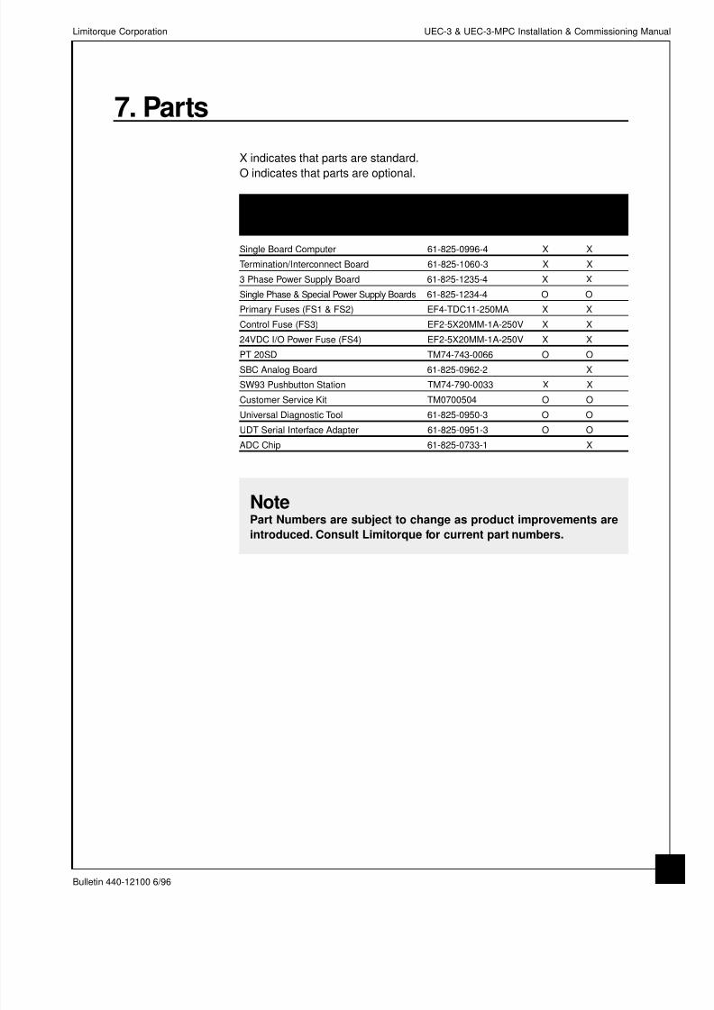
7. Parts
X indicates that parts are standard.
O indicates that parts are optional.
Item Part Number UEC MPC
Single Board Computer 61-825-0996-4 X X
Termination/Interconnect Board 61-825-1060-3 X X
3 Phase Power Supply Board 61-825-1235-4 X X
Single Phase & Special Power Supply Boards 61-825-1234-4 O O
Primary Fuses (FS1 & FS2) EF4-TDC11-250MA X X
Control Fuse (FS3) EF2-5X20MM-1A-250V X X
24VDC I/O Power Fuse (FS4) EF2-5X20MM-1A-250V X X
PT 20SD TM74-743-0066 O O
SBC Analog Board 61-825-0962-2 X
SW93 Pushbutton Station TM74-790-0033 X X
Customer Service Kit TM0700504 O O
Universal Diagnostic Tool 61-825-0950-3 O O
UDT Serial Interface Adapter 61-825-0951-3 O O
ADC Chip 61-825-0733-1 X
NotePart Numbers are subject to change as product improvements are
introduced. Consult Limitorque for current part numbers.
Limitorque Corporation UEC-3 & UEC-3-MPC Installation & Commissioning Manua
Bulletin 440-12100 6/96
3

8/12/2019 Uec 3 & Uec3 Mpc Manual440-12100
http://slidepdf.com/reader/full/uec-3-uec3-mpc-manual440-12100 38/40
This page is intentionally blank.
Limitorque Corporation UEC-3 & UEC-3-MPC Installation & Commissioning Manual
Bulletin 440-12100 6/96
34

8/12/2019 Uec 3 & Uec3 Mpc Manual440-12100
http://slidepdf.com/reader/full/uec-3-uec3-mpc-manual440-12100 39/40
8. Customer ServiceFor parts or parts information, call your local Limitorque distributor or the Parts
Department in Lynchburg, VA, at 804-522-9833. For fastest response, please
have the order number and serial number from the actuator available when
contacting Limitorque for parts or parts information. This information can befound on a Limitorque label affixed to the main housing of the actuator.
For service information, call your local Limitorque distributor, Blue Ribbon
Service Center or the Service Department in Lynchburg, VA, at 804-845-9366.
For fastest service, please have the order number and serial number from the
actuator available when contacting Limitorque with service questions. This
information can be found on a Limitorque label affixed to the main housing of
the actuator.
Limitorque Corporation UEC-3 & UEC-3-MPC Installation & Commissioning Manua
Bulletin 440-12100 6/96
3

8/12/2019 Uec 3 & Uec3 Mpc Manual440-12100
http://slidepdf.com/reader/full/uec-3-uec3-mpc-manual440-12100 40/40
Limitorque ®
Bulletin 440-12100 6/96
For further Limitorque service assistance call:
Limitorque Corporation
7615 Boeing Drive
Greensboro, NC 27409-8347
Phone (910) 668-0871
Fax (910) 605-5310
Limitorque Corporation
8901 Jameel Road Suite 180
Houston, TX 77040
Phone (713) 690-1960
Fax (713) 690-1277
or contact the Limitorque offices listed below
Limitorque Corporation
5114 Woodall RoadP.O. Box 11318Lynchburg, VA
24506-1318Phone (804) 528-4400
Fax (804) 845-9736
Limitorque International
Trinity HouseKennet SideNewburyBerkshire, RG15 5EH EnglandPhone 44-1-635-46999Fax 44-1-635-36034
Limitorque/Nippon Gear Co. Ltd.Tennoz Central Tower 2-2-4,Higashi-Shinagawa,
Limitorque of India, Ltd.
E-45/2 Okhla Industrial Area,Phase-IINew Delhi 110 020, IndiaPhone 91-129-277135Fax 91-11-683-9329
Limitorque Australia Ltd.Division of Control Engineering(Aust.) Pty., Ltd.17 Scoresby Road
Limitorque Asia Pte Ltd.
75 Bukit Timah Rd.#05-01/02 Boon Siew BuildingSingapore 229833Phone 65-332-9100Fax 65-332-9112