Embed Size (px)
Citation preview
Part Number 900-303 Revision D December 2007
UDS200 User Guide

2
Copyright & Trademark © 2004, 2007 Lantronix. All rights reserved. No part of the contents of this book may be transmitted or reproduced in any form or by any means without the written permission of Lantronix. Printed in the United States of America.
Ethernet is a trademark of XEROX Corporation. UNIX is a registered trademark of The Open Group. Windows 95, Windows 98, Windows 2000, and Windows NT are trademarks of Microsoft Corp. Netscape is a trademark of Netscape Communications Corporation.
Contacts Lantronix Corporate Headquarters 15353 Barranca Parkway Irvine, CA 92618, USA Phone: 949-453-3990 Fax: 949-453-3995
Technical Support http://www.lantronix.com/support Sales Offices For a current list of our domestic and international sales offices, go to the Lantronix web site at www.lantronix.com/about/contact.
Disclaimer & Revisions Operation of this equipment in a residential area is likely to cause interference, in which case the user, at his or her own expense, will be required to take whatever measures may be required to correct the interference.
Note: This product has been designed to comply with the limits for a Class A digital device pursuant to Part 15 of FCC Rules. These limits are designed to provide reasonable protection against such interference when operating in a commercial environment. This equipment generates, uses, and can radiate radio frequency energy, and if not installed and used in accordance with this guide, may cause harmful interference to radio communications.
Changes or modifications to this device not explicitly approved by Lantronix will void the user's authority to operate this device.
The information in this guide may change without notice. The manufacturer assumes no responsibility for any errors that may appear in this guide.
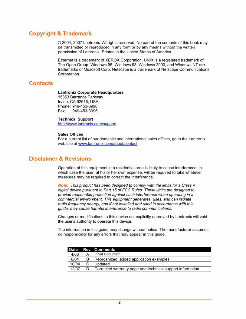
Date Rev. Comments 4/03 A Initial Document 6/04 B Reorganized, added application examples 10/04 C Updated 12/07 D Corrected warranty page and technical support information
3
Contents Figures 6
Tables 6
1: Using This Guide 7 Purpose and Audience _______________________________________________ 7 Chapter Summary ___________________________________________________ 7 Additional Documentation _____________________________________________ 8
2: Introduction 9 Applications ________________________________________________________ 9 Application Examples ________________________________________________ 9 Protocol Support ___________________________________________________ 10 Additional Features _________________________________________________ 11 Configuration Methods ______________________________________________ 11 Product Information Label ____________________________________________ 11
3: Getting Started 12 Installing the UDS200 _______________________________________________ 12 Required Information________________________________________________ 13
Hardware Address ______________________________________________________ 13 IP Address_____________________________________________________________ 13
Assigning the IP Address and Related Network Settings ____________________ 14 DeviceInstaller__________________________________________________________ 14 Serial Port Login ________________________________________________________ 15
4: Configuring the UDS Using Web Manager 16 Accessing Web Manager_____________________________________________ 16 Configuring the UDS ________________________________________________ 18
5: Configuring the UDS Using Telnet or the Serial Port 20 Using a Telnet Connection ________________________________________________ 20 Using the Serial Port _____________________________________________________ 22
Server Configuration (Network Configuration)_____________________________ 22 IP Address_____________________________________________________________ 22 Set Gateway IP Address__________________________________________________ 23 Netmask ______________________________________________________________ 23 Change Telnet configuration password ______________________________________ 23
4
DHCP Naming _________________________________________________________ 23 Channel 1 Configuration (Serial Port Settings) ____________________________ 24
Baudrate______________________________________________________________ 24 I/F (Interface) Mode _____________________________________________________ 24 Flow _________________________________________________________________ 25 Port Number___________________________________________________________ 25 Connect Mode _________________________________________________________ 26 Manual Connection _____________________________________________________ 27 Remote IP Address _____________________________________________________ 30 Remote Port ___________________________________________________________ 30 Disconnect Mode _______________________________________________________ 31 Flush Mode____________________________________________________________ 31 Pack Control___________________________________________________________ 32 Disconnect Time (Inactivity Timeout)________________________________________ 33 Send Characters _______________________________________________________ 33 Telnet Terminal Type ____________________________________________________ 33 Channel (Port) Password _________________________________________________ 33
Expert Settings_____________________________________________________ 33 TCP Keepalive time in s__________________________________________________ 34 ARP Cache timeout in s __________________________________________________ 34
Security Settings ___________________________________________________ 34 Disable SNMP _________________________________________________________ 34 SNMP Community Name _________________________________________________ 34 Disable Telnet Setup ____________________________________________________ 35 Disable TFTP Firmware Upgrade __________________________________________ 35 Disable Port 77FE (Hex) _________________________________________________ 35 Disable Web Setup______________________________________________________ 35 Disable ECHO Ports_____________________________________________________ 35 Enable Enhanced Password ______________________________________________ 35
Factory Default Settings______________________________________________ 36 Channel 1 and Channel 2 Configuration Defaults ______________________________ 36 Expert Settings Defaults__________________________________________________ 36 Security Settings Defaults ________________________________________________ 36
Exiting Configuration Mode ___________________________________________ 36
6: Updating Firmware 37 Obtaining Firmware _________________________________________________ 37 Reloading Firmware_________________________________________________ 37
Using DeviceInstaller ____________________________________________________ 37 Using TFTP ___________________________________________________________ 38
5
Using Another Unit ______________________________________________________ 39 Using the Serial Port _____________________________________________________ 39
7: Using Monitor Mode 41 Entering Monitor Mode Using the Serial Port _____________________________ 41 Entering Monitor Mode Using the Network _______________________________ 41 Using Monitor Mode Commands _______________________________________ 42
8: Troubleshooting and Technical Support 43 LEDs ____________________________________________________________ 43 Problems and Error Messages ________________________________________ 44 Technical Support __________________________________________________ 47
9: Technical Specifications 49
10: Connections and Pinouts 50 UDS200 Serial Ports_____________________________________________________ 50 Serial Connector Pinouts _________________________________________________ 50 Network Port ___________________________________________________________ 51 Ethernet Connector Pinouts _______________________________________________ 51 Null-Modem Cable ______________________________________________________ 51
A: Alternative Ways to Assign an IP Address 53 DHCP ________________________________________________________________ 53 AutoIP ________________________________________________________________ 53 BOOTP _______________________________________________________________ 54 ARP and Telnet_________________________________________________________ 54
B: Binary to Hexadecimal Conversions 55 Converting Binary to Hexadecimal _____________________________________ 55
Conversion Table _______________________________________________________ 55 Scientific Calculator _____________________________________________________ 56
Connect Mode Options ______________________________________________ 57 Disconnect Mode Options ____________________________________________ 60 Flush Mode (Buffer Flushing) Options___________________________________ 62 Interface Mode Options ______________________________________________ 67 Pack Control Options________________________________________________ 67
Declaration of Conformity 69
Warranty 70
Index 71
6
Figures Figure 2-1. Application Examples ........................................................................................................ 10 Figure 2-2. Sample Hardware Address................................................................................................ 11 Figure 3-1. UDS200 Connected to Serial Device and Network........................................................... 12 Figure 4-1. Web Browser Login ........................................................................................................... 16 Figure 4-2. UDS Configuration Guidelines Page ................................................................................. 17 Figure 4-3. Lantronix Web Manager .................................................................................................... 18 Figure 4-4. Server Properties Configuration on the Web Browser ...................................................... 19 Figure 5-1. Network Login Using Telnet .............................................................................................. 20 Figure 5-2. Setup Mode Window ......................................................................................................... 21 Figure 5-3. Network Configuration ....................................................................................................... 22 Figure 5-4. Server Configuration Option .............................................................................................. 24 Figure 5-5. Channel 1 Configuration.................................................................................................... 24 Figure 5-6. Hostlist Option ................................................................................................................... 28 Figure 5-7. Expert Settings Options..................................................................................................... 33 Figure 5-8. Security Settings................................................................................................................ 34 Figure 6-1. TFTP Dialog Box ............................................................................................................... 38 Figure 6-2. Sending Firmware to another Unit..................................................................................... 39 Figure 6-3. Firmware Upgrade Screen Display................................................................................... 39 Figure 7-1. Entering Monitor Mode Using the Network........................................................................ 41 Figure 10-1. Serial Interface................................................................................................................. 50 Figure 10-2. DB9 Male RS232 Serial DTE Connector......................................................................... 50 Figure 10-3. Network Interface ............................................................................................................ 51 Figure 10-4. RJ45 Ethernet Connector ................................................................................................ 51 Figure 10-5. Null-Modem Cable (Lantronix Part No. 500-164) ............................................................ 52
Tables Table 5-1. Netmask Examples 23 Table 5-2. Interface Mode Options 25 Table 5-3. Common Interface Mode Settings 25 Table 5-4. Flow Control Options 25 Table 5-5. Connect Mode Options 26 Table 5-6. Manual Connection Address Example 27 Table 5-7. Modem Mode Commands 30 Table 5-8. Disconnect Mode Options 31 Table 5-9. Flush Mode Options 31 Table 5-10. Pack Control Options 32 Table 7-1. Monitor Mode Commands 42 Table 7-2. Command Response Codes 42 Table 8-1. UDS200 LEDs 44 Table 8-2. Problems and Error Messages 44
7
11:: UUssiinngg TThhiiss GGuuiiddee
Purpose and Audience
This guide provides the information needed to configure, use, and update the UDS200 device server. It is for system administrators and those responsible for installing and maintaining the UDS200.
Chapter Summary
The remaining chapters in this guide include:
2: Introduction Describes the main features of the UDS200 and the protocols it supports.
3: Getting Started Provides information for installing your unit and getting it up and running.
4: Configuring the UDS Using Web Manager
Provides instructions for accessing Web Manager and using it to configure settings for the UDS.
5: Configuring the UDS Using Telnet or the Serial Port
Provides instructions for accessing Setup Mode (command line interface) using a Telnet connection through the network or a terminal or terminal emulation program through the serial port. Details the settings that you must configure.
6: Updating Firmware Provides instructions for obtaining the latest firmware and updating the UDS200.
7: Using Monitor Mode Provides instructions for accessing and using the command line interface to monitor the network and diagnose problems.
8: Troubleshooting and Technical Support
Describes common problems and error messages and how to contact Lantronix Technical Support.
9: Technical Specifications Lists technical specifications for the UDS200.
10: Connections and Pinouts Provides descriptions and illustrations of connection hardware.
A: Alternative Ways to Assign an IP Address
Provides detailed information about using DHCP, AutoIP, BOOTP ARP, and Telnet to assign an IP address.
B: Binary to Hexadecimal Provides instructions on converting binary values to hexadecimals and tables listing all configuration options in hexadecimal notation.
UDS200 User Guide Using This Guide
8
Additional Documentation
The following guide is available on the product CD or the Lantronix Web site: www.lantronix.com.
DeviceInstaller User Guide
Provides instructions for using the Windows-based utility to configure the UDS and other Lantronix device servers. (CD and web site)
9
22:: IInnttrroodduuccttiioonn
Applications
The UDS family of Device Servers allows serial devices, such as those listed below, to connect and communicate over Ethernet networks using the IP protocol family (TCP for connection-oriented stream applications and UDP for datagram applications).
Security alarms
Access control devices
Fire control panels
Time/attendance clocks and terminals
ATM machines
Data collection devices
RFID readers
Universal Power Supply (UPS) management units
Telecommunications equipment
Data display devices
Virtually any asynchronous RS-232, RS422, or RS485 device.
Application Examples
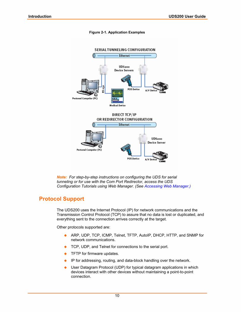
Using a method called serial tunneling, the UDS200 encapsulates serial data into packets and transports them over Ethernet. Using two UDS200 units, connected by a network, virtual serial connections can extend across a facility or around the world.
The Com Port Redirector software included on the product CD simplifies the integration process by extending the functionality of COM-port-based Windows™ applications. Virtual COM ports, mapped to remote device servers on the network, can replace direct serial connections.
Introduction UDS200 User Guide
10
Figure 2-1. Application Examples
Note: For step-by-step instructions on configuring the UDS for serial tunneling or for use with the Com Port Redirector, access the UDS Configuration Tutorials using Web Manager. (See Accessing Web Manager.)
Protocol Support
The UDS200 uses the Internet Protocol (IP) for network communications and the Transmission Control Protocol (TCP) to assure that no data is lost or duplicated, and everything sent to the connection arrives correctly at the target.
Other protocols supported are:
ARP, UDP, TCP, ICMP, Telnet, TFTP, AutoIP, DHCP, HTTP, and SNMP for network communications.
TCP, UDP, and Telnet for connections to the serial port.
TFTP for firmware updates.
IP for addressing, routing, and data-block handling over the network.
User Datagram Protocol (UDP) for typical datagram applications in which devices interact with other devices without maintaining a point-to-point connection.
Introduction UDS200 User Guide
11
Additional Features
Modem Emulation: In modem emulation mode, the UDS200 can replace dial-up modems. The unit accepts modem AT commands on the serial port, and then establishes a network connection to the end device, leveraging network connections and bandwidth to eliminate dedicated modems and phone lines.
Built-in Web Server: The UDS200 includes a built-in web server for configuring the unit and displaying operating and troubleshooting information on the attached links to online support.
Configuration Methods
After installation, the UDS200 requires configuration. For the unit to operate correctly on a network, it must have a unique IP address on the network. There are three basic methods for logging into the UDS200 and assigning IP addresses and other configurable settings:
DeviceInstaller: Configure the IP address and other network settings on the UDS200 using a Graphical User Interface (GUI) on a PC attached to a network. See DeviceInstaller on page 14.)
Web Manager: Through a web interface, configure the UDS200 settings using the Lantronix Web Manager. (See 4: Configuring the UDS Using Web Manager.)
Serial and Telnet Ports: There are two approaches to accessing Setup Mode: making a Telnet connection to the network port (9999) or connecting a terminal (or a PC running a terminal emulation program) to the unit’s serial port. (See 5: Configuring the UDS Using Telnet or the Serial Port.)
Product Information Label
The product information label on the underside of the unit contains the following information about your specific unit:
Bar code
Serial number
Product ID (name)
Product description
Hardware address (also referred to as Ethernet or MAC address)
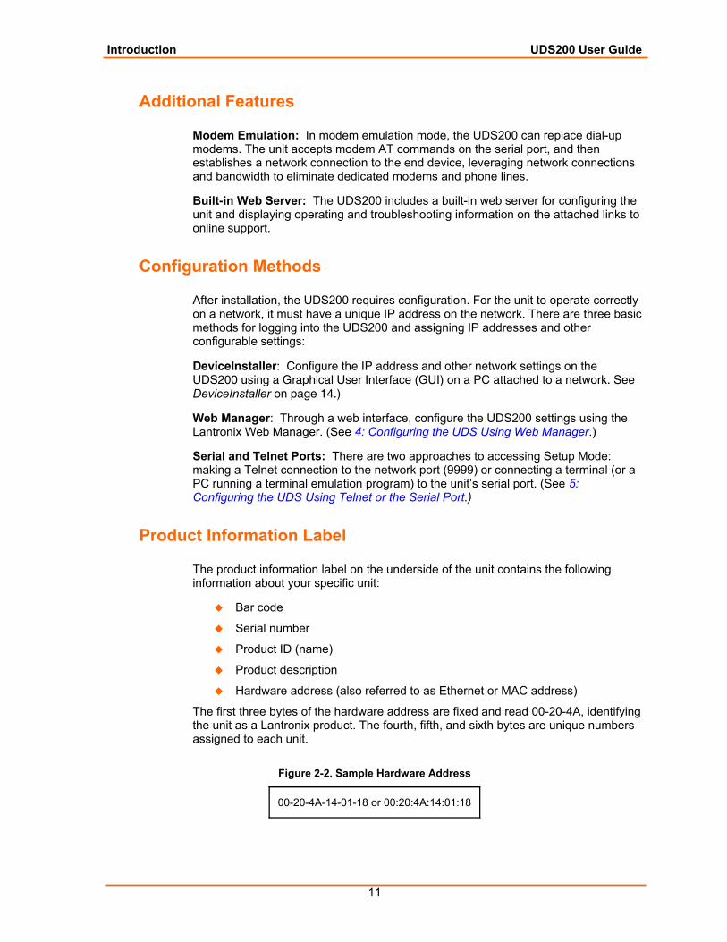
The first three bytes of the hardware address are fixed and read 00-20-4A, identifying the unit as a Lantronix product. The fourth, fifth, and sixth bytes are unique numbers assigned to each unit.
Figure 2-2. Sample Hardware Address
00-20-4A-14-01-18 or 00:20:4A:14:01:18
12
33:: GGeettttiinngg SSttaarrtteedd This chapter describes how to get your UDS up and running in the shortest possible time.
Installing the UDS200
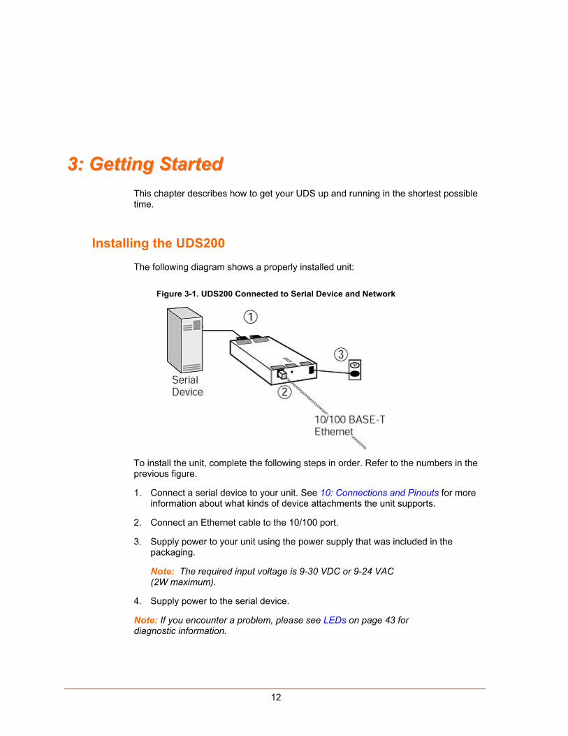
The following diagram shows a properly installed unit:
Figure 3-1. UDS200 Connected to Serial Device and Network
To install the unit, complete the following steps in order. Refer to the numbers in the previous figure.
1. Connect a serial device to your unit. See 10: Connections and Pinouts for more information about what kinds of device attachments the unit supports.
2. Connect an Ethernet cable to the 10/100 port.
3. Supply power to your unit using the power supply that was included in the packaging.
Note: The required input voltage is 9-30 VDC or 9-24 VAC (2W maximum).
4. Supply power to the serial device.
Note: If you encounter a problem, please see LEDs on page 43 for diagnostic information.
Getting Started UDS200 User Guide
13
Required Information
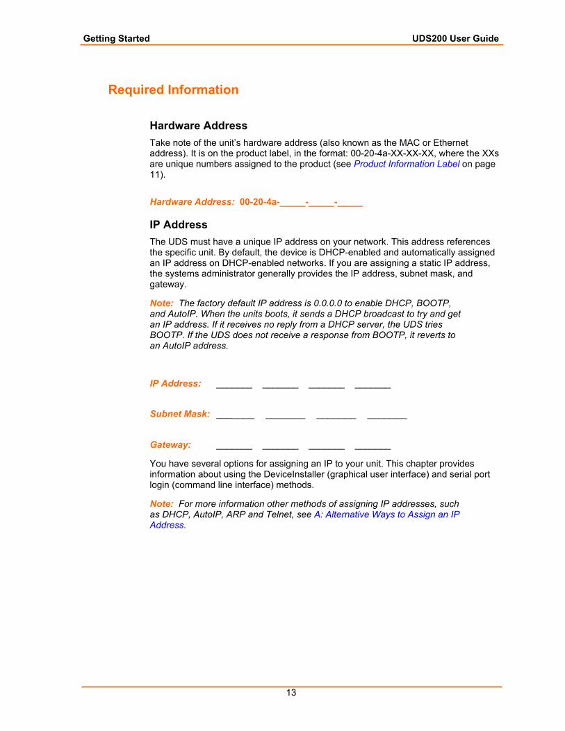
Hardware Address Take note of the unit’s hardware address (also known as the MAC or Ethernet address). It is on the product label, in the format: 00-20-4a-XX-XX-XX, where the XXs are unique numbers assigned to the product (see Product Information Label on page 11).
Hardware Address: 00-20-4a-_____-_____-_____
IP Address The UDS must have a unique IP address on your network. This address references the specific unit. By default, the device is DHCP-enabled and automatically assigned an IP address on DHCP-enabled networks. If you are assigning a static IP address, the systems administrator generally provides the IP address, subnet mask, and gateway.
Note: The factory default IP address is 0.0.0.0 to enable DHCP, BOOTP, and AutoIP. When the units boots, it sends a DHCP broadcast to try and get an IP address. If it receives no reply from a DHCP server, the UDS tries BOOTP. If the UDS does not receive a response from BOOTP, it reverts to an AutoIP address.
IP Address: _______ _______ _______ _______
Subnet Mask: _______ _______ _______ _______
Gateway: _______ _______ _______ _______
You have several options for assigning an IP to your unit. This chapter provides information about using the DeviceInstaller (graphical user interface) and serial port login (command line interface) methods.
Note: For more information other methods of assigning IP addresses, such as DHCP, AutoIP, ARP and Telnet, see A: Alternative Ways to Assign an IP Address.
Getting Started UDS200 User Guide
14
Assigning the IP Address and Related Network Settings
This section describes two ways to assign the IP address and related network settings quickly:
DeviceInstaller
Serial Port Login
DeviceInstaller Note: The DeviceInstaller User Guide and the DeviceInstaller online help provide more detailed information on using DeviceInstaller.
Installing DeviceInstaller To use the DeviceInstaller utility, you first install it from the product CD.
1. Insert the product CD into your CD-ROM drive. The Lantronix UDS10/UDS100 DeviceInstaller window displays.
2. If the CD does not launch automatically:
a) Click the Start button on the Task Bar and select Run.
b) Enter your CD drive letter, colon, backslash, deviceinstaller.exe (e.g., E:\deviceinstaller.exe).
3. Click the DeviceInstaller button. The installation wizard window displays.
4. Respond to the installation wizard prompts. (When prompted to select an installation type, select Typical.)
Assigning the IP Address and Network Class 1. Click the Start button on the Task Bar and select Programs Lantronix
DeviceInstaller DeviceInstaller. The DeviceInstaller window displays.
2. Click the Assign IP icon. The Assign IP Address window displays.
3. Enter the Hardware or Ethernet address of the device.
4. Select Assign a specific IP address to assign a static IP address to the device, or select Obtain an IP address automatically to enable BOOTP, DHCP, or Auto IP on the device.
5. Click Next.
6. Enter an IP address, subnet mask, and gateway for the device. Enter this information in XXX.XXX.XXX.XXX format.
7. Click Next.
8. Click the Assign button to finalize the IP assignment.
Getting Started UDS200 User Guide
15
Adding the Unit to the Manage List Now add the unit to the list of similar Lantronix devices on the network so that you can manage and configure it. To perform this step, click the Search icon.
DeviceInstaller locates the unit and adds it to the list. Now you can manage (configure) the unit so that it works with the serial device on the network.
Methods of Configuring the UDS Now that the UDS has an IP address and other initial settings, you can configure it further by several methods.
Note: To assign Expert settings and Security settings, you must use the Setup Mode window in a Telnet session.
To configure the unit using a Web browser, click the Web icon. The Lantronix Web Manager window displays in your browser. Continue with 4: Configuring the UDS Using Web Manager.
To configure the unit using a Telnet session or the serial port, click the Telnet icon. The Setup Mode window displays. Continue with 5: Configuring the UDS Using Telnet or the Serial Port.
Serial Port Login To assign the IP address and other network settings using a serial connection, follow these steps:
1. Connect a console terminal or a PC running a terminal emulation program to the unit's serial port. The default serial port settings are 9600 baud, 8 bits, no parity, 1 stop bit, no flow control.
2. To enter Setup Mode, cycle the unit's power (power off and back on). After power-up, the self-test begins and the red Diagnostic LED starts blinking. You have one second to enter three lowercase x characters.
Note: The easiest way to enter Setup Mode is to hold down the x key at the terminal (or emulation) while powering up the unit.
3. Select 0 (Server Configuration) and follow the prompts until you get to IP address.
4. Enter the new IP address, subnet mask, and gateway (if applicable).
5. Do one of the following:
Continue with 5: Configuring the UDS Using Telnet or the Serial Port.
Select 9 to save and exit Setup Mode. The unit performs a power reset.
16
44:: CCoonnffiigguurriinngg tthhee UUDDSS UUssiinngg WWeebb MMaannaaggeerr You must configure the UDS so that it can communicate on a network with your serial device. For example, you must set the way the unit responds to serial and network traffic, handles serial packets, and starts and closes connections.
This chapter gives an overview of the procedure for using Web Manager to configure a UDS. This is the easiest and preferred method.
The unit’s configuration is stored in nonvolatile memory (NVRam) and is retained without power. You can change the configuration at any time. The unit performs a reset after the configuration has been changed and stored.
Note: When configuring the UDS200, note that it does not support 2 stop bits for port 2.
Accessing Web Manager
If your unit already has an IP address, you can log into it using a standard Web browser with Java enabled.
Note: You can also access Web Manager by clicking the Web icon on the DeviceInstaller “Manage List” window (see Methods of Configuring the UDS on page 15.)
1. Type the unit's IP address into the Web browser's URL (Address/Location) field.
Figure 4-1. Web Browser Login
2. When the UDS Configuration Guidelines Page displays, select one of the four
links:
Configuring the UDS Using Web Manager UDS200 User Guide
17
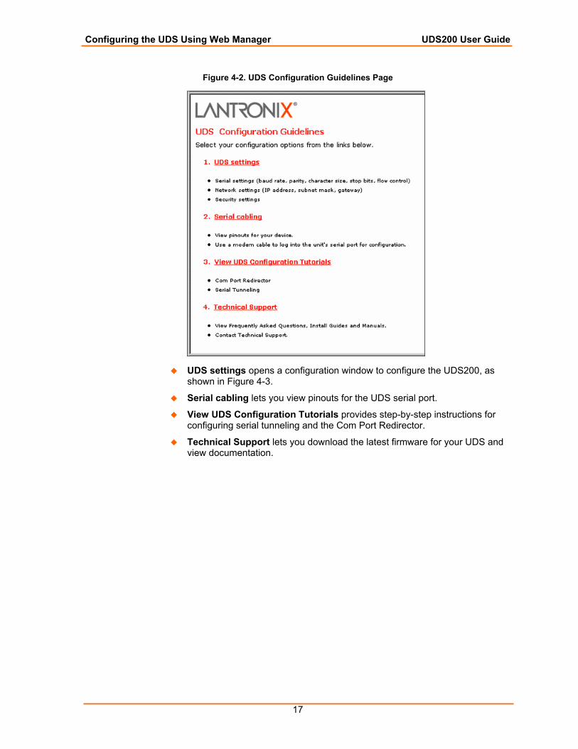
Figure 4-2. UDS Configuration Guidelines Page
UDS settings opens a configuration window to configure the UDS200, as shown in Figure 4-3.
Serial cabling lets you view pinouts for the UDS serial port.
View UDS Configuration Tutorials provides step-by-step instructions for configuring serial tunneling and the Com Port Redirector.
Technical Support lets you download the latest firmware for your UDS and view documentation.
Configuring the UDS Using Web Manager UDS200 User Guide
18
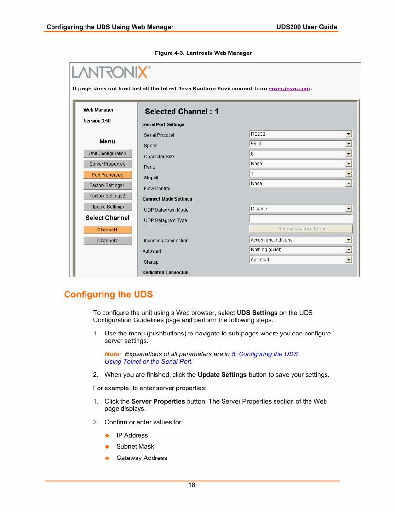
Figure 4-3. Lantronix Web Manager
Configuring the UDS
To configure the unit using a Web browser, select UDS Settings on the UDS Configuration Guidelines page and perform the following steps.
1. Use the menu (pushbuttons) to navigate to sub-pages where you can configure server settings.
Note: Explanations of all parameters are in 5: Configuring the UDS Using Telnet or the Serial Port.
2. When you are finished, click the Update Settings button to save your settings.
For example, to enter server properties:
1. Click the Server Properties button. The Server Properties section of the Web page displays.
2. Confirm or enter values for:
IP Address
Subnet Mask
Gateway Address
Configuring the UDS Using Web Manager UDS200 User Guide
19
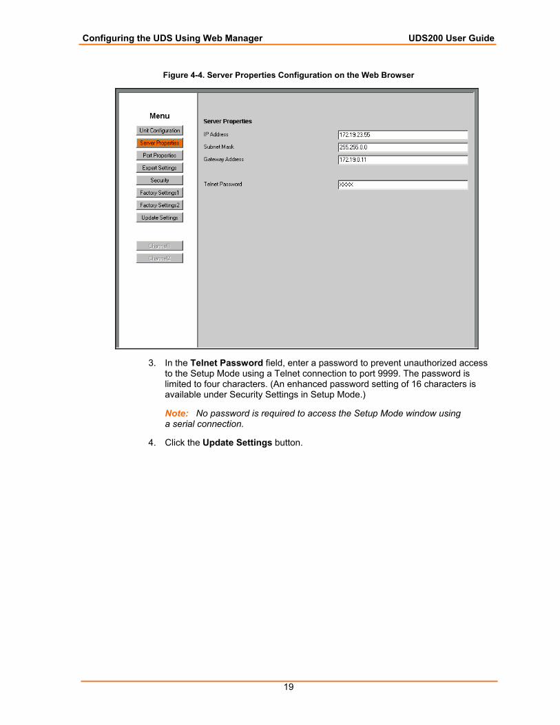
Figure 4-4. Server Properties Configuration on the Web Browser
3. In the Telnet Password field, enter a password to prevent unauthorized access to the Setup Mode using a Telnet connection to port 9999. The password is limited to four characters. (An enhanced password setting of 16 characters is available under Security Settings in Setup Mode.)
Note: No password is required to access the Setup Mode window using a serial connection.
4. Click the Update Settings button.

20
55:: CCoonnffiigguurriinngg tthhee UUDDSS UUssiinngg TTeellnneett oorr tthhee SSeerriiaall PPoorrtt
You must configure the UDS so that it can communicate on a network with your serial device. For example, you must set the way the unit will respond to serial and network traffic, how it will handle serial packets, and when to start or close a connection.
As an alternative to using Web Manager, configure the UDS using a series of prompts referred to as Setup Mode, accessed through a Telnet or a serial port connection. Once you access the screen, the configuration procedure is identical.
The unit’s configuration is stored in nonvolatile memory (NVRam) and is retained without power. You can change the configuration at any time. The unit performs a reset after the configuration has been changed and stored.
This chapter provides instructions on using Setup Mode and detailed explanations of the configuration settings.
Note: When configuring the UDS200, note that it does not support 2 stop bits for port 2.
Using a Telnet Connection To configure the unit over the network, establish a Telnet connection to port 9999.
Note: You can also establish a Telnet connection by clicking the Telnet icon on the DeviceInstaller “Manage List” window (see Methods of Configuring the UDS on page 15.)
1. From the Windows Start menu, click Run and type the following command, where x.x.x.x is the IP address and 9999 is the unit’s fixed network configuration port number.
Figure 5-1. Network Login Using Telnet
telnet x.x.x.x 9999
Note: Be sure to include a space between the IP address and 9999.
2. Click OK. To remain in Setup Mode, you must press Enter within 5 seconds.
The configuration settings display, followed by the Change Setup menu.
Configuring the UDS Using Telnet or the Serial Port UDS200 User Guide
21
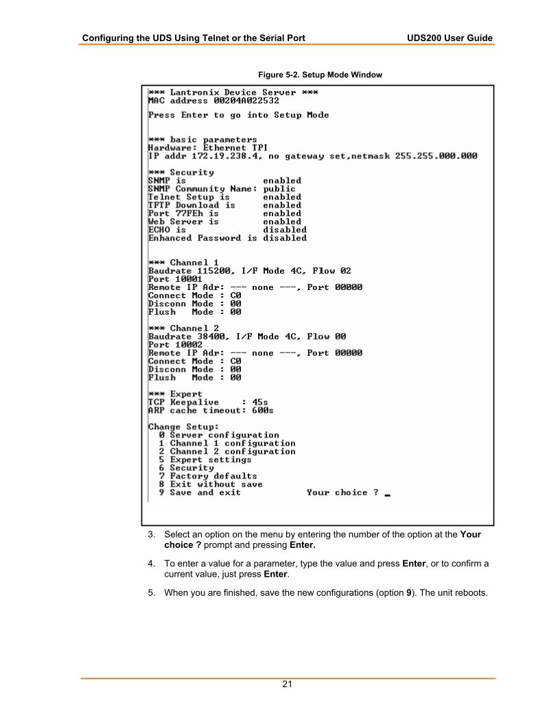
Figure 5-2. Setup Mode Window
3. Select an option on the menu by entering the number of the option at the Your choice ? prompt and pressing Enter.
4. To enter a value for a parameter, type the value and press Enter, or to confirm a current value, just press Enter.
5. When you are finished, save the new configurations (option 9). The unit reboots.
Configuring the UDS Using Telnet or the Serial Port UDS200 User Guide
22
Using the Serial Port For local configuration, you can connect a terminal or a PC running a terminal emulation program to the unit’s serial port (channel 1). Configure the terminal (or emulation) for 9600 baud, 8-bit, no parity, 1 stop bit, and no flow control.
1. Cycle the unit’s power (power off and back on). After power-up, the self-test begins and the diagnostic and status LEDs start blinking.
2. Type three lowercase x characters (xxx) within one second after powering up in order to start the configuration mode. The Setup Mode window displays. (See the example in Using a Telnet Connection.)
Note: The easiest way to enter Setup Mode is to hold down the x key on your keyboard while powering up the unit.
3. Select an option on the menu by entering the number of the option at the Your choice ? prompt and pressing Enter.
4. To enter a value for a parameter, type the value and press Enter, or to confirm a default value, just press Enter.
5. When you are finished, save the new configuration (option 9). The unit reboots.
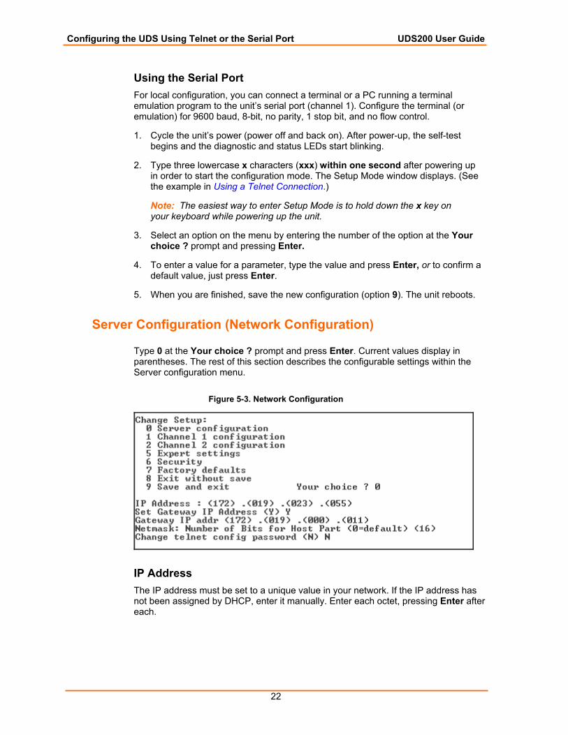
Server Configuration (Network Configuration)
Type 0 at the Your choice ? prompt and press Enter. Current values display in parentheses. The rest of this section describes the configurable settings within the Server configuration menu.
Figure 5-3. Network Configuration
IP Address The IP address must be set to a unique value in your network. If the IP address has not been assigned by DHCP, enter it manually. Enter each octet, pressing Enter after each.
Configuring the UDS Using Telnet or the Serial Port UDS200 User Guide
23
Set Gateway IP Address The gateway address, or router, allows communication to other LAN segments. The gateway address should be the IP address of the router connected to the same LAN segment as the unit. The gateway address must be within the local network.
Netmask A netmask defines the number of bits taken from the IP address for the host section. The host section is the part of the IP address that is specific to the UDS.
Note: Class A: 24 bits; Class B: 16 bits; Class C: 8 bits.
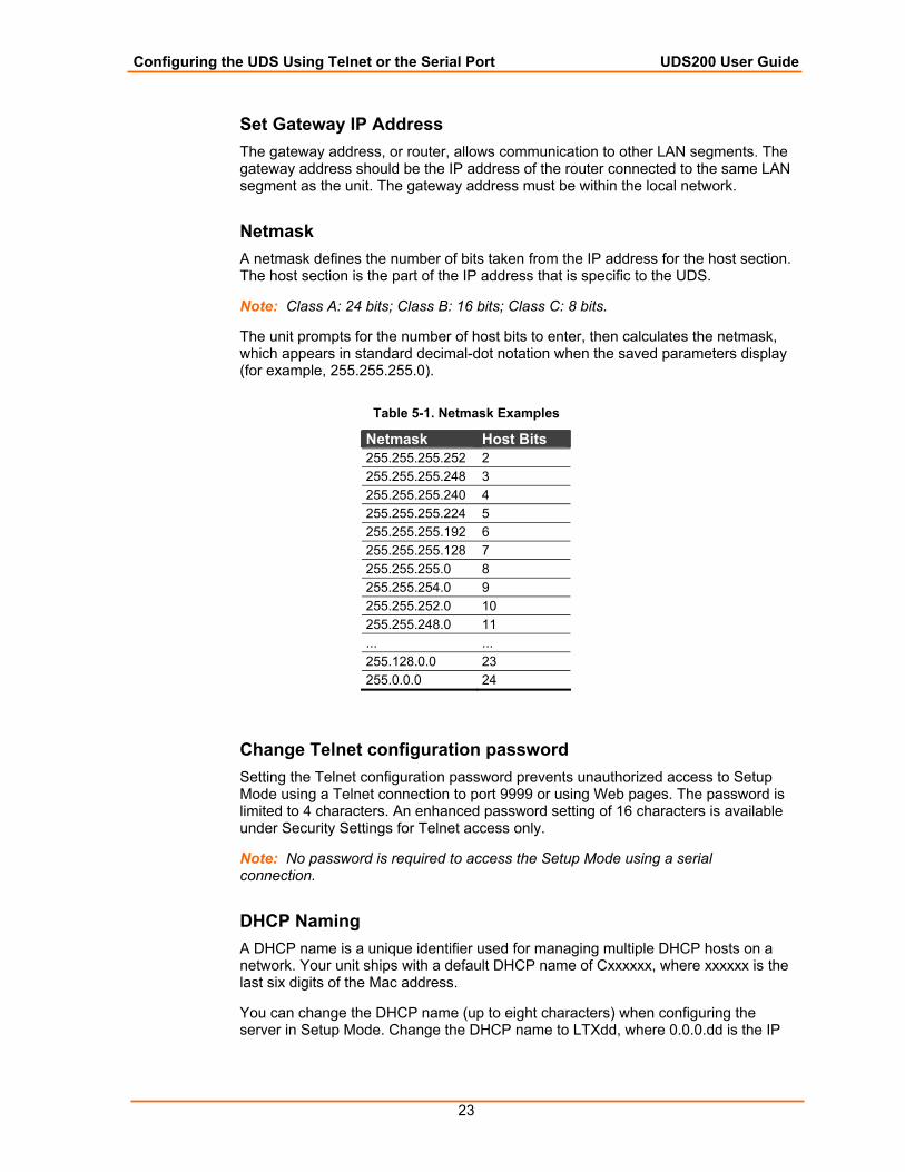
The unit prompts for the number of host bits to enter, then calculates the netmask, which appears in standard decimal-dot notation when the saved parameters display (for example, 255.255.255.0).
Table 5-1. Netmask Examples
Netmask Host Bits 255.255.255.252 2 255.255.255.248 3 255.255.255.240 4 255.255.255.224 5 255.255.255.192 6 255.255.255.128 7 255.255.255.0 8 255.255.254.0 9 255.255.252.0 10 255.255.248.0 11 ... ... 255.128.0.0 23 255.0.0.0 24
Change Telnet configuration password Setting the Telnet configuration password prevents unauthorized access to Setup Mode using a Telnet connection to port 9999 or using Web pages. The password is limited to 4 characters. An enhanced password setting of 16 characters is available under Security Settings for Telnet access only.
Note: No password is required to access the Setup Mode using a serial connection.
DHCP Naming A DHCP name is a unique identifier used for managing multiple DHCP hosts on a network. Your unit ships with a default DHCP name of Cxxxxxx, where xxxxxx is the last six digits of the Mac address.
You can change the DHCP name (up to eight characters) when configuring the server in Setup Mode. Change the DHCP name to LTXdd, where 0.0.0.dd is the IP
Configuring the UDS Using Telnet or the Serial Port UDS200 User Guide
24
address assigned (dd should be a number between 1 and 99). For example, if the IP address is set to 0.0.0.5, the resulting DHCP name is LTX05.
If you give the unit an IP of 0.0.0.0, you then have the option to assign an 8-character DHCP name.
Figure 5-4. Server Configuration Option
Change DHCP device name (LTRX) ? (N) Y Enter new DHCP device name : LTRXYES
Channel 1 Configuration (Serial Port Settings)
Note: Some fields require entries in hexadecimal notation. A simple way to convert a binary number to a hexadecimal is to use a scientific calculator, such as the one available in Windows. For more information, see B: Binary to Hexadecimal Conversions.
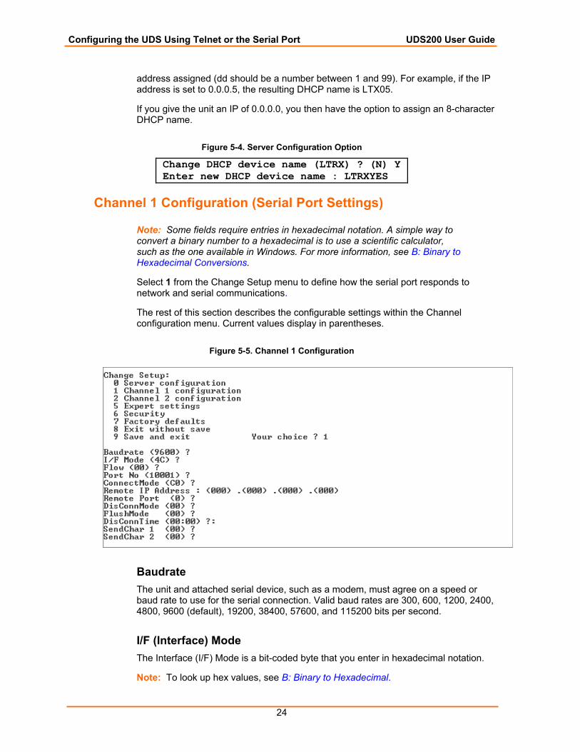
Select 1 from the Change Setup menu to define how the serial port responds to network and serial communications.
The rest of this section describes the configurable settings within the Channel configuration menu. Current values display in parentheses.
Figure 5-5. Channel 1 Configuration
Baudrate The unit and attached serial device, such as a modem, must agree on a speed or baud rate to use for the serial connection. Valid baud rates are 300, 600, 1200, 2400, 4800, 9600 (default), 19200, 38400, 57600, and 115200 bits per second.
I/F (Interface) Mode The Interface (I/F) Mode is a bit-coded byte that you enter in hexadecimal notation.
Note: To look up hex values, see B: Binary to Hexadecimal.
Configuring the UDS Using Telnet or the Serial Port UDS200 User Guide
25
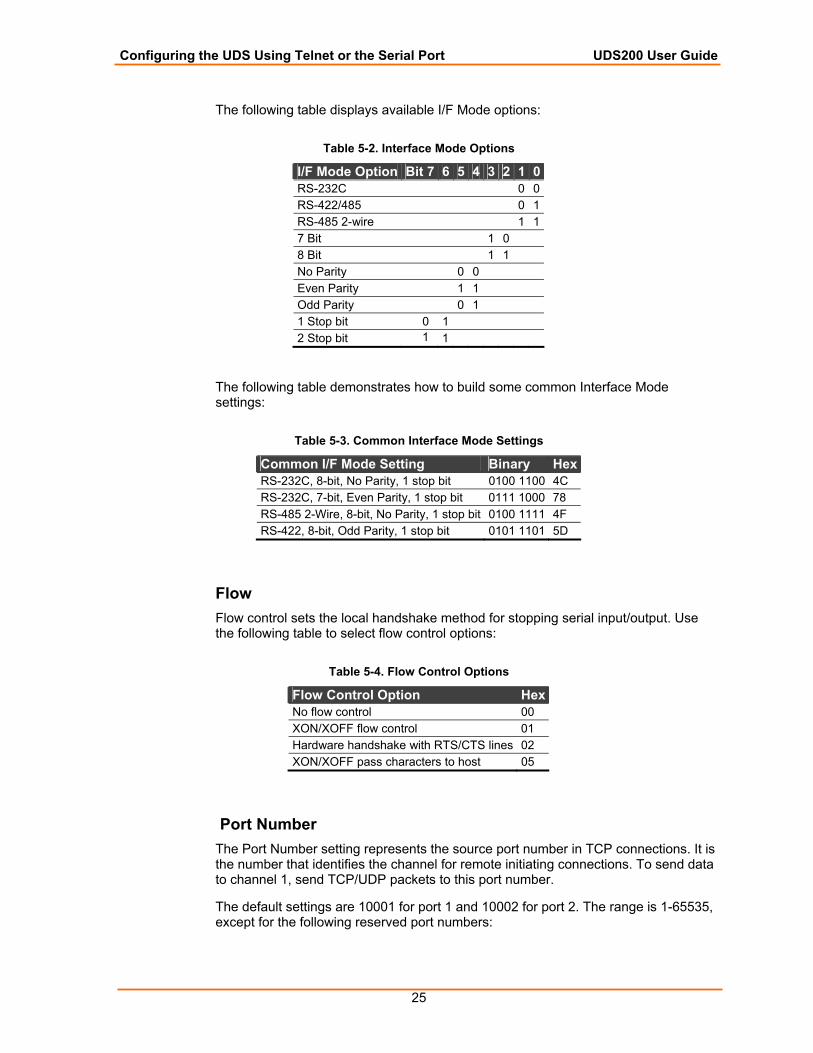
The following table displays available I/F Mode options:
Table 5-2. Interface Mode Options
I/F Mode Option Bit 7 6 5 4 3 2 1 0RS-232C 0 0RS-422/485 0 1RS-485 2-wire 1 17 Bit 1 0 8 Bit 1 1 No Parity 0 0 Even Parity 1 1 Odd Parity 0 1 1 Stop bit 0 1 2 Stop bit 1 1
The following table demonstrates how to build some common Interface Mode settings:
Table 5-3. Common Interface Mode Settings
Common I/F Mode Setting Binary Hex RS-232C, 8-bit, No Parity, 1 stop bit 0100 1100 4C RS-232C, 7-bit, Even Parity, 1 stop bit 0111 1000 78 RS-485 2-Wire, 8-bit, No Parity, 1 stop bit 0100 1111 4F RS-422, 8-bit, Odd Parity, 1 stop bit 0101 1101 5D
Flow Flow control sets the local handshake method for stopping serial input/output. Use the following table to select flow control options:
Table 5-4. Flow Control Options
Flow Control Option HexNo flow control 00 XON/XOFF flow control 01 Hardware handshake with RTS/CTS lines 02 XON/XOFF pass characters to host 05
Port Number The Port Number setting represents the source port number in TCP connections. It is the number that identifies the channel for remote initiating connections. To send data to channel 1, send TCP/UDP packets to this port number.
The default settings are 10001 for port 1 and 10002 for port 2. The range is 1-65535, except for the following reserved port numbers:
Configuring the UDS Using Telnet or the Serial Port UDS200 User Guide
26
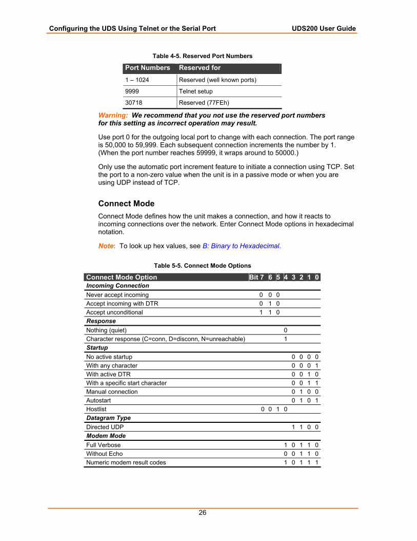
Table 4-5. Reserved Port Numbers
Port Numbers Reserved for
1 – 1024 Reserved (well known ports)
9999 Telnet setup
30718 Reserved (77FEh)
Warning: We recommend that you not use the reserved port numbers for this setting as incorrect operation may result.
Use port 0 for the outgoing local port to change with each connection. The port range is 50,000 to 59,999. Each subsequent connection increments the number by 1. (When the port number reaches 59999, it wraps around to 50000.)
Only use the automatic port increment feature to initiate a connection using TCP. Set the port to a non-zero value when the unit is in a passive mode or when you are using UDP instead of TCP.
Connect Mode Connect Mode defines how the unit makes a connection, and how it reacts to incoming connections over the network. Enter Connect Mode options in hexadecimal notation.
Note: To look up hex values, see B: Binary to Hexadecimal.
Table 5-5. Connect Mode Options
Connect Mode Option Bit 7 6 5 4 3 2 1 0 Incoming Connection Never accept incoming 0 0 0 Accept incoming with DTR 0 1 0 Accept unconditional 1 1 0 Response Nothing (quiet) 0 Character response (C=conn, D=disconn, N=unreachable) 1 Startup No active startup 0 0 0 0 With any character 0 0 0 1 With active DTR 0 0 1 0 With a specific start character 0 0 1 1 Manual connection 0 1 0 0 Autostart 0 1 0 1 Hostlist 0 0 1 0 Datagram Type Directed UDP 1 1 0 0 Modem Mode Full Verbose 1 0 1 1 0 Without Echo 0 0 1 1 0 Numeric modem result codes 1 0 1 1 1
Configuring the UDS Using Telnet or the Serial Port UDS200 User Guide
27
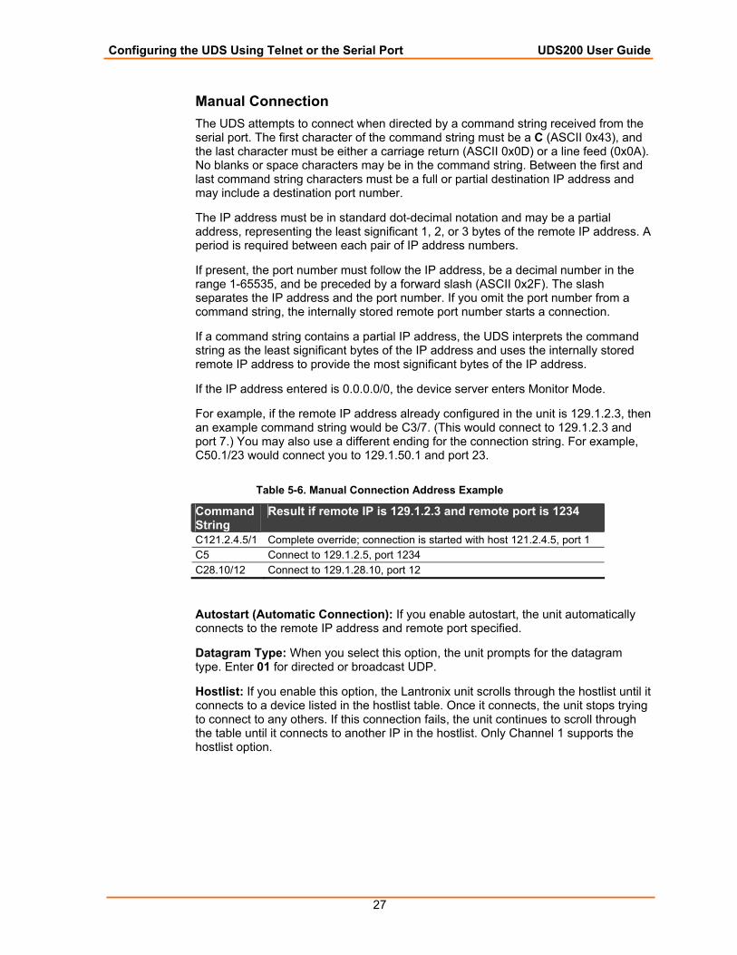
Manual Connection The UDS attempts to connect when directed by a command string received from the serial port. The first character of the command string must be a C (ASCII 0x43), and the last character must be either a carriage return (ASCII 0x0D) or a line feed (0x0A). No blanks or space characters may be in the command string. Between the first and last command string characters must be a full or partial destination IP address and may include a destination port number.
The IP address must be in standard dot-decimal notation and may be a partial address, representing the least significant 1, 2, or 3 bytes of the remote IP address. A period is required between each pair of IP address numbers.
If present, the port number must follow the IP address, be a decimal number in the range 1-65535, and be preceded by a forward slash (ASCII 0x2F). The slash separates the IP address and the port number. If you omit the port number from a command string, the internally stored remote port number starts a connection.
If a command string contains a partial IP address, the UDS interprets the command string as the least significant bytes of the IP address and uses the internally stored remote IP address to provide the most significant bytes of the IP address.
If the IP address entered is 0.0.0.0/0, the device server enters Monitor Mode.
For example, if the remote IP address already configured in the unit is 129.1.2.3, then an example command string would be C3/7. (This would connect to 129.1.2.3 and port 7.) You may also use a different ending for the connection string. For example, C50.1/23 would connect you to 129.1.50.1 and port 23.
Table 5-6. Manual Connection Address Example
Command String
Result if remote IP is 129.1.2.3 and remote port is 1234
C121.2.4.5/1 Complete override; connection is started with host 121.2.4.5, port 1 C5 Connect to 129.1.2.5, port 1234 C28.10/12 Connect to 129.1.28.10, port 12
Autostart (Automatic Connection): If you enable autostart, the unit automatically connects to the remote IP address and remote port specified.
Datagram Type: When you select this option, the unit prompts for the datagram type. Enter 01 for directed or broadcast UDP.
Hostlist: If you enable this option, the Lantronix unit scrolls through the hostlist until it connects to a device listed in the hostlist table. Once it connects, the unit stops trying to connect to any others. If this connection fails, the unit continues to scroll through the table until it connects to another IP in the hostlist. Only Channel 1 supports the hostlist option.
Configuring the UDS Using Telnet or the Serial Port UDS200 User Guide
28
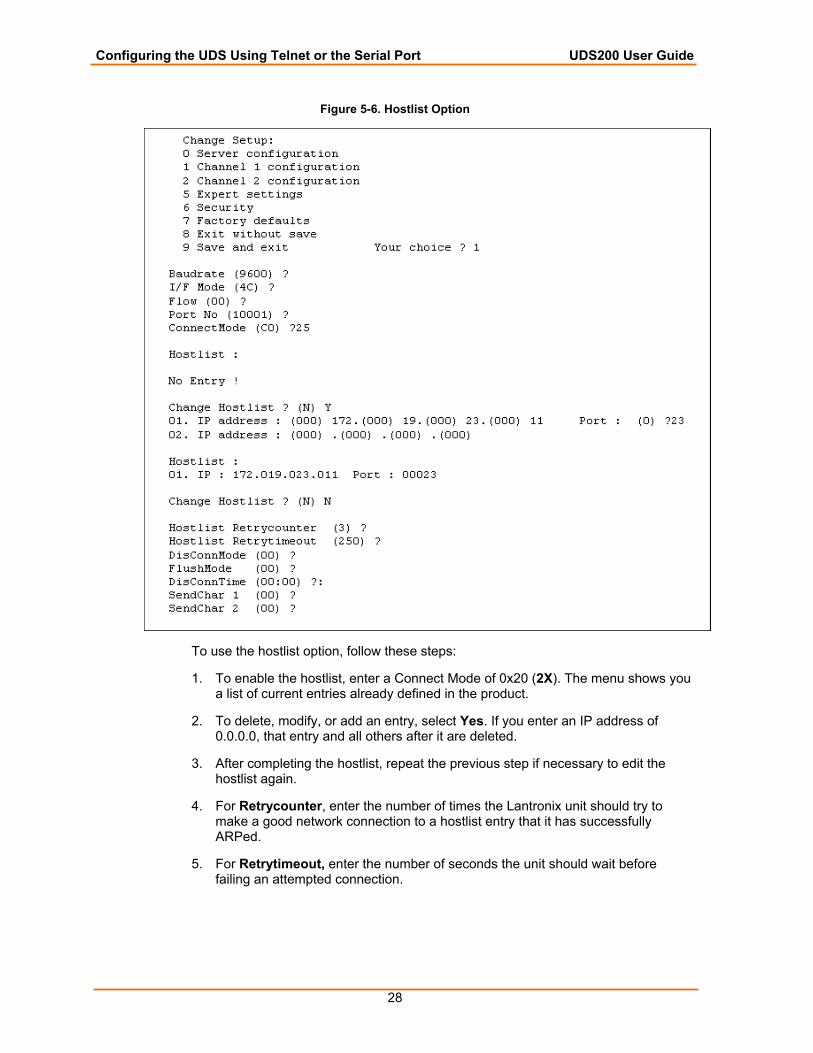
Figure 5-6. Hostlist Option
To use the hostlist option, follow these steps:
1. To enable the hostlist, enter a Connect Mode of 0x20 (2X). The menu shows you a list of current entries already defined in the product.
2. To delete, modify, or add an entry, select Yes. If you enter an IP address of 0.0.0.0, that entry and all others after it are deleted.
3. After completing the hostlist, repeat the previous step if necessary to edit the hostlist again.
4. For Retrycounter, enter the number of times the Lantronix unit should try to make a good network connection to a hostlist entry that it has successfully ARPed.
5. For Retrytimeout, enter the number of seconds the unit should wait before failing an attempted connection.
Configuring the UDS Using Telnet or the Serial Port UDS200 User Guide
29
Modem (Emulation) Mode: In Modem Mode, the unit presents a modem interface to the attached serial device. It accepts AT-style modem commands, and handles the modem signals correctly.
Normally there is a modem connected to a local PC and a modem connected to a remote machine. A user must dial from the local PC to the remote machine, accumulating phone charges for each connection. Modem Mode allows you to replace modems with UDS units, and to use an Ethernet connection instead of a phone call. By not having to change communications applications, you avoid potentially expensive phone calls.
To select Modem Mode, set the Connect Mode to C6 (no echo), D6 (echo with full verbose), or D7 (echo with 1-character response).
Note: If the unit is in Modem Mode, and the serial port is idle, the unit still accepts network TCP connections to the serial port if Connect Mode is set to C6 (no echo), D6 (echo with full verbose), or D7 (echo with 1-character response).
Echo: Refers to the echo of all of the characters entered in command mode; it does not mean to echo data that is transferred. Quiet Mode (no echo) refers to the modem not sending an answer to the commands received (or displaying what was typed).
Full Verbose: The unit echoes modem commands and responds to a command with a message string.
1-Character Response: The unit echoes modem commands and responds to a command with a single character response.
To disconnect a connection using Modem Mode commands:
1. Ensure the following:
There must be a 1-second guardtime (no data traffic) before sending +++.
There must not be a break longer than 1 second between +s.
There must be another 1-second guardtime after the last + is sent.
2. When the unit acknowledges with an OK to indicate that it is in command mode, enter ATH and press Enter. The command is echoed if echo is enabled. ATH is acknowledged by another OK.
Configuring the UDS Using Telnet or the Serial Port UDS200 User Guide
30
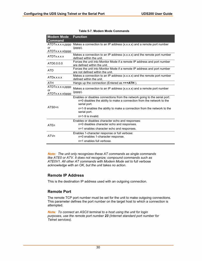
Table 5-7. Modem Mode Commands
Modem Mode Command
Function
ATDTx.x.x.x,pppp or ATDTx.x.x.x/pppp
Makes a connection to an IP address (x.x.x.x) and a remote port number (pppp).
ATDTx.x.x.x Makes a connection to an IP address (x.x.x.x) and the remote port number defined within the unit.
ATD0.0.0.0 Forces the unit into Monitor Mode if a remote IP address and port number are defined within the unit.
ATD Forces the unit into Monitor Mode if a remote IP address and port number are not defined within the unit.
ATDx.x.x.x Makes a connection to an IP address (x.x.x.x) and the remote port number defined within the unit.
ATH Hangs up the connection (Entered as +++ATH ). ATDTx.x.x.x,pppp or ATDTx.x.x.x/pppp
Makes a connection to an IP address (x.x.x.x) and a remote port number (pppp).
ATS0=n
Enables or disables connections from the network going to the serial port: n=0 disables the ability to make a connection from the network to the serial port. n=1-9 enables the ability to make a connection from the network to the serial port. n>1-9 is invalid.
ATEn Enables or disables character echo and responses:
n=0 disables character echo and responses. n=1 enables character echo and responses.
ATVn
Enables 1-character response or full verbose: n=0 enables 1-character response. n=1 enables full verbose.
Note: The unit only recognizes these AT commands as single commands like ATE0 or ATV. It does not recognize; compound commands such as ATE0V1. All other AT commands with Modem Mode set to full verbose acknowledge with an OK, but the unit takes no action.
Remote IP Address This is the destination IP address used with an outgoing connection.
Remote Port The remote TCP port number must be set for the unit to make outgoing connections. This parameter defines the port number on the target host to which a connection is attempted.
Note: To connect an ASCII terminal to a host using the unit for login purposes, use the remote port number 23 (Internet standard port number for Telnet services).
Configuring the UDS Using Telnet or the Serial Port UDS200 User Guide
31
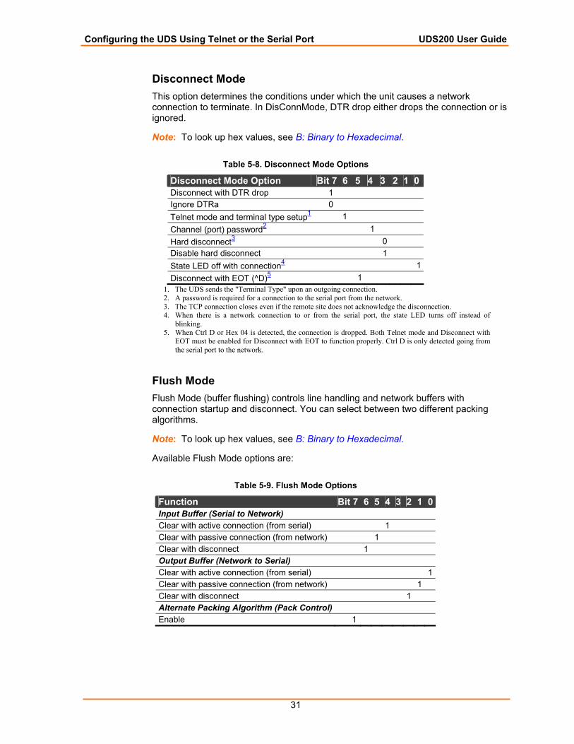
Disconnect Mode This option determines the conditions under which the unit causes a network connection to terminate. In DisConnMode, DTR drop either drops the connection or is ignored.
Note: To look up hex values, see B: Binary to Hexadecimal.
Table 5-8. Disconnect Mode Options
Disconnect Mode Option Bit 7 6 5 4 3 2 1 0 Disconnect with DTR drop 1 Ignore DTRa 0 Telnet mode and terminal type setup1 1 Channel (port) password2 1 Hard disconnect3 0 Disable hard disconnect 1 State LED off with connection4 1 Disconnect with EOT (^D)5 1
1. The UDS sends the "Terminal Type" upon an outgoing connection. 2. A password is required for a connection to the serial port from the network. 3. The TCP connection closes even if the remote site does not acknowledge the disconnection. 4. When there is a network connection to or from the serial port, the state LED turns off instead of
blinking. 5. When Ctrl D or Hex 04 is detected, the connection is dropped. Both Telnet mode and Disconnect with
EOT must be enabled for Disconnect with EOT to function properly. Ctrl D is only detected going from the serial port to the network.
Flush Mode Flush Mode (buffer flushing) controls line handling and network buffers with connection startup and disconnect. You can select between two different packing algorithms.
Note: To look up hex values, see B: Binary to Hexadecimal.
Available Flush Mode options are:
Table 5-9. Flush Mode Options
Function Bit 7 6 5 4 3 2 1 0 Input Buffer (Serial to Network) Clear with active connection (from serial) 1 Clear with passive connection (from network) 1 Clear with disconnect 1 Output Buffer (Network to Serial) Clear with active connection (from serial) 1 Clear with passive connection (from network) 1 Clear with disconnect 1 Alternate Packing Algorithm (Pack Control) Enable 1
Configuring the UDS Using Telnet or the Serial Port UDS200 User Guide
32
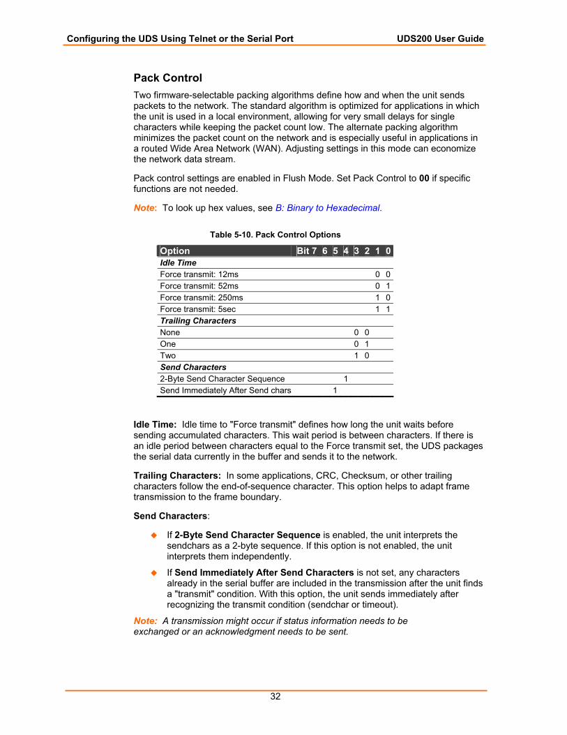
Pack Control Two firmware-selectable packing algorithms define how and when the unit sends packets to the network. The standard algorithm is optimized for applications in which the unit is used in a local environment, allowing for very small delays for single characters while keeping the packet count low. The alternate packing algorithm minimizes the packet count on the network and is especially useful in applications in a routed Wide Area Network (WAN). Adjusting settings in this mode can economize the network data stream.
Pack control settings are enabled in Flush Mode. Set Pack Control to 00 if specific functions are not needed.
Note: To look up hex values, see B: Binary to Hexadecimal.
Table 5-10. Pack Control Options
Option Bit 7 6 5 4 3 2 1 0Idle Time Force transmit: 12ms 0 0Force transmit: 52ms 0 1Force transmit: 250ms 1 0Force transmit: 5sec 1 1Trailing Characters None 0 0 One 0 1 Two 1 0 Send Characters 2-Byte Send Character Sequence 1 Send Immediately After Send chars 1
Idle Time: Idle time to "Force transmit" defines how long the unit waits before sending accumulated characters. This wait period is between characters. If there is an idle period between characters equal to the Force transmit set, the UDS packages the serial data currently in the buffer and sends it to the network.
Trailing Characters: In some applications, CRC, Checksum, or other trailing characters follow the end-of-sequence character. This option helps to adapt frame transmission to the frame boundary.
Send Characters:
If 2-Byte Send Character Sequence is enabled, the unit interprets the sendchars as a 2-byte sequence. If this option is not enabled, the unit interprets them independently.
If Send Immediately After Send Characters is not set, any characters already in the serial buffer are included in the transmission after the unit finds a "transmit" condition. With this option, the unit sends immediately after recognizing the transmit condition (sendchar or timeout).
Note: A transmission might occur if status information needs to be exchanged or an acknowledgment needs to be sent.

Configuring the UDS Using Telnet or the Serial Port UDS200 User Guide
33
Disconnect Time (Inactivity Timeout) Use Disconnect Time to set an inactivity timeout. The unit drops the connection if there is no activity on the serial line before the set time expires. Enter time in the following format: mm:ss, where m is the number of minutes and s is the number of seconds. To disable the inactivity timeout, enter 00:00. Range is 0 (disabled) to 5999 seconds (99 minutes, 59 seconds). The default is 0.
Send Characters Enter up to two characters in hexadecimal representation for the SendChar settings. If the unit receives a character on the serial line that matches one of these characters, it sends the character immediately, along with any awaiting characters, to the TCP connection. This action minimizes the response time for specific protocol characters on the serial line (for example, ETX, EOT). Setting the first SendChar to 00 disables the recognition of the characters. Alternatively, the unit can interpret two characters as a sequence (see Pack Control on page 32).
Telnet Terminal Type This parameter displays only if the terminal type option is enabled in Disconnect Mode. If this option is enabled, use the terminal name for the Telnet terminal type. Enter only one name.
If the terminal type option is enabled, the unit also reacts to the EOR (end of record) and binary options used for applications like terminal emulation to IBM hosts.
Channel (Port) Password This parameter displays only if the channel (port) password option is enabled in Disconnect Mode. If the option is enabled, set a password on the serial port.
Expert Settings
Note: Change these settings using Telnet or serial connections only, not Web Manager.
Caution: Only an expert should change these parameters. These changes have serious consequences.
Figure 5-7. Expert Settings Options
Configuring the UDS Using Telnet or the Serial Port UDS200 User Guide
34
TCP Keepalive time in s This option defines how many seconds the unit waits during a silent connection before checking to see whether the currently connected network device is still on the network. If the unit does not receive a response, it drops that connection.
ARP Cache timeout in s When the unit communicates with another device on the network, it adds an entry into its ARP table. The ARP Cache timeout option defines the number of seconds (1-600) the unit waits before timing out an entry in this table.
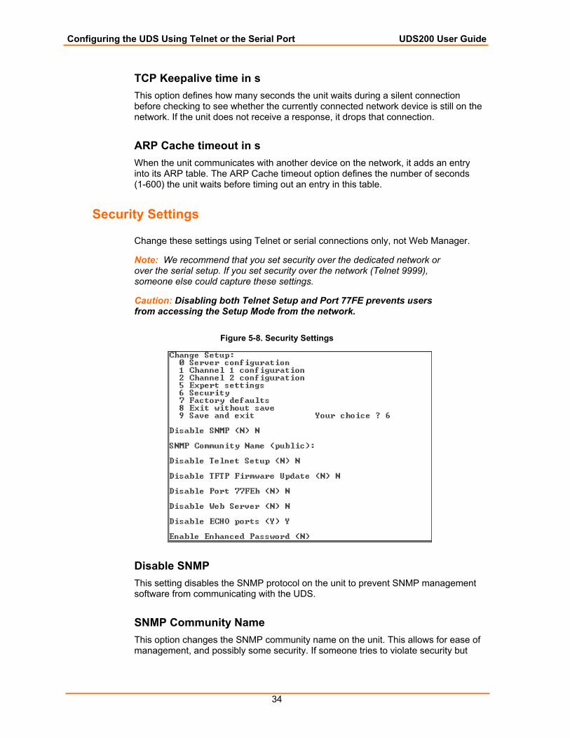
Security Settings
Change these settings using Telnet or serial connections only, not Web Manager.
Note: We recommend that you set security over the dedicated network or over the serial setup. If you set security over the network (Telnet 9999), someone else could capture these settings.
Caution: Disabling both Telnet Setup and Port 77FE prevents users from accessing the Setup Mode from the network.
Figure 5-8. Security Settings
Disable SNMP This setting disables the SNMP protocol on the unit to prevent SNMP management software from communicating with the UDS.
SNMP Community Name This option changes the SNMP community name on the unit. This allows for ease of management, and possibly some security. If someone tries to violate security but
Configuring the UDS Using Telnet or the Serial Port UDS200 User Guide
35
does not know what community to connect to, that person is unable to obtain the SNMP community information from the unit. The default is public.
Disable Telnet Setup Caution: Disabling both Telnet Setup and Port 77FE prevents users from accessing Setup Mode from the network.
This setting defaults to the N (No) option. The Y (Yes) option disables access to Setup Mode by Telnet (port 9999). It only allows access locally using Web Manager and the serial port of the unit.
Disable TFTP Firmware Upgrade This setting defaults to the N (No) option. The Y (Yes) option disables TFTP for network firmware upgrades. With this option, firmware upgrades can be performed only by using a *.hex file over the serial port of the unit.
Disable Port 77FE (Hex) Caution: Disabling both Telnet Setup and Port 77FE prevents users from accessing the Setup Mode from the network.
DeviceInstaller, Web Manager, and custom programs use Port 77FE to configure the unit remotely. If required, disable this capability for security purposes.
The default setting is the N (No) option, which enables remote configuration. As a result, configure the unit by using DeviceInstaller, Web Manager, Telnet, or serial configuration.
The Y (Yes) option disables remote configuration and Web Manager.
Note: the Y (Yes) option disables many of the GUI tools for configuring the unit, including Web Manager.
Disable Web Setup The Y (Yes) option disables the use of Web Manager. It disables browser-initiated sessions to port 80 on the UDS and configuration using HTTP. Port 80 is closed.
Disable ECHO Ports Port 7 accepts Telnet and UDP connections. Whatever data is sent to this port is echoed back to the sender. This setting disables the use of the echo server that is built into the unit.
Enable Enhanced Password This setting defaults to the N (No) option, which permits a 4-character password that protects the Setup Mode using Telnet and Web Manager. The Y (Yes) option allows an extended security password of 16-characters for protecting Telnet access.
Configuring the UDS Using Telnet or the Serial Port UDS200 User Guide
36
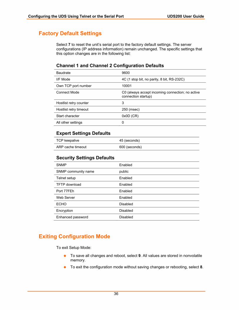
Factory Default Settings
Select 7 to reset the unit’s serial port to the factory default settings. The server configurations (IP address information) remain unchanged. The specific settings that this option changes are in the following list:
Channel 1 and Channel 2 Configuration Defaults Baudrate 9600
I/F Mode 4C (1 stop bit, no parity, 8 bit, RS-232C)
Own TCP port number 10001
Connect Mode C0 (always accept incoming connection; no active connection startup)
Hostlist retry counter 3
Hostlist retry timeout 250 (msec)
Start character 0x0D (CR)
All other settings 0
Expert Settings Defaults TCP keepalive 45 (seconds)
ARP cache timeout 600 (seconds)
Security Settings Defaults SNMP Enabled
SNMP community name public
Telnet setup Enabled
TFTP download Enabled
Port 77FEh Enabled
Web Server Enabled
ECHO Disabled
Encryption Disabled
Enhanced password Disabled
Exiting Configuration Mode
To exit Setup Mode:
To save all changes and reboot, select 9. All values are stored in nonvolatile memory.
To exit the configuration mode without saving changes or rebooting, select 8.
37
66:: UUppddaattiinngg FFiirrmmwwaarree
Obtaining Firmware
You can obtain the most up-to-date firmware and release notes for the unit from the Lantronix Web site (http://www.lantronix.com/) or by using anonymous FTP (ftp://ftp.lantronix.com/).
Reloading Firmware
There are several ways to update the unit's internal operational code (U200*.ROM or U200*.HEX): using DeviceInstaller (the preferred way), TFTP, another unit, or a serial port. You can also update the unit's internal Web interface (CBXW*.COB) using TFTP or DeviceInstaller.
Using DeviceInstaller After downloading the firmware to your computer, you can use DeviceInstaller to install it.
1. Download the updated firmware files from www.lantronix.com or ftp://ftp.lantronix.com/ and store them in a subfolder on your computer.
2. Click the Start button on the Task Bar and select Programs Lantronix DeviceInstaller DeviceInstaller. The DeviceInstaller window displays.
3. Click the Search the network for devices icon. The Search Network window displays.
4. Once located by DeviceInstaller, highlight the device in the device list and click the Upgrade button (which displays after you select the device). Select a custom installation by specifying the individual files and clicking Next.
5. Click the Browse button to select the location of the firmware file to load, and then click Next.
6. Select Do not copy or replace any files and click Next.
Note: This option upgrades the firmware file (.ROM file) only, not the Web Manager files (.COB).
7. Click Next again. The status of the upgrade displays in the window.
8. After the upgrade completes, click Close.
Updating Firmware UDS200 User Guide
38
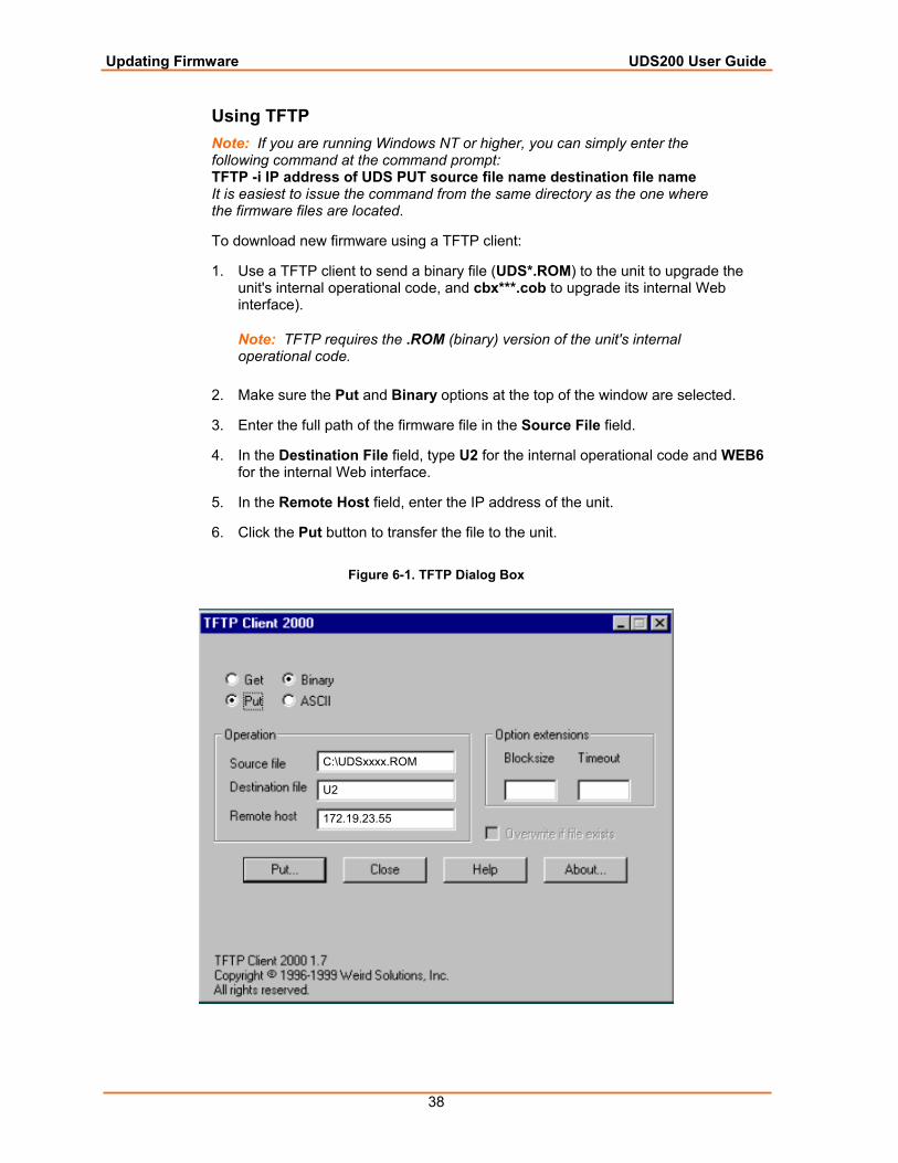
Using TFTP Note: If you are running Windows NT or higher, you can simply enter the following command at the command prompt: TFTP -i IP address of UDS PUT source file name destination file name It is easiest to issue the command from the same directory as the one where the firmware files are located.
To download new firmware using a TFTP client:
1. Use a TFTP client to send a binary file (UDS*.ROM) to the unit to upgrade the unit's internal operational code, and cbx***.cob to upgrade its internal Web interface).
Note: TFTP requires the .ROM (binary) version of the unit's internal operational code.
2. Make sure the Put and Binary options at the top of the window are selected.
3. Enter the full path of the firmware file in the Source File field.
4. In the Destination File field, type U2 for the internal operational code and WEB6 for the internal Web interface.
5. In the Remote Host field, enter the IP address of the unit.
6. Click the Put button to transfer the file to the unit.
Figure 6-1. TFTP Dialog Box
C:\UDSxxxx.ROM
U2
172.19.23.55
Updating Firmware UDS200 User Guide
39
The unit performs a power reset after the firmware has been loaded and stored.
Using Another Unit To distribute firmware to another unit over the network:
1. Enter the host unit's Monitor Mode (see Entering Monitor Mode Using the Serial Port on page 41).
2. Send the firmware to the receiving unit using the SF command, where x.x.x.x is the receiving unit's IP address.
Figure 6-2. Sending Firmware to another Unit
SF x.x.x.x
After loading and storing the firmware, the receiving unit performs a power reset
Note: You can only update your unit’s internal Web interface using TFTP or DeviceInstaller.
Using the Serial Port The following procedure is for using the HyperTerminal software application. This procedure takes about 10 minutes.
Note: Do not switch off the power supply during the update. A loss of power while reprogramming will result in a corrupt program image and a nonfunctional unit.
To download firmware from a computer using the unit’s serial port:
1. Enter Monitor Mode using the serial port (see 7: Using Monitor Mode).
2. Download the firmware to the unit using the DL command.
3. Select Send Text File and select the U200*.HEX file to be downloaded. The downloaded file must be the .HEX (ASCII) version.
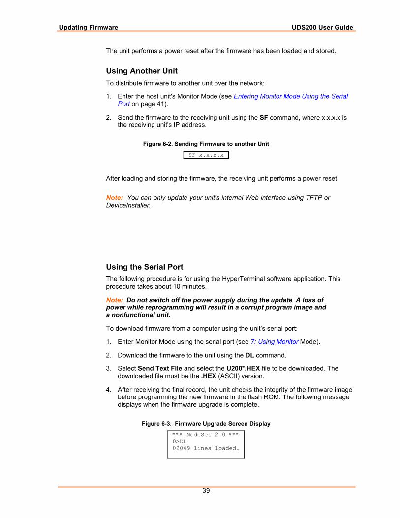
4. After receiving the final record, the unit checks the integrity of the firmware image before programming the new firmware in the flash ROM. The following message displays when the firmware upgrade is complete.
Figure 6-3. Firmware Upgrade Screen Display
*** NodeSet 2.0 *** 0>DL 02049 lines loaded.

Updating Firmware UDS200 User Guide
40
Note: You can only update your unit’s internal Web interface using TFTP or DeviceInstaller.
41
77:: UUssiinngg MMoonniittoorr MMooddee Monitor Mode is a command line interface used for diagnostic purposes. There are two ways to enter Monitor Mode: locally using the serial port or remotely using the network.
Entering Monitor Mode Using the Serial Port
To enter Monitor Mode locally, follow the same principles used in setting the serial configuration settings:
1. Do one of the following:
To enter Monitor Mode with network connections, type xx1 or zzz (not three x keys as you did before).
To enter Monitor Mode without network connections, type xx2 or yyy.
A 0> prompt indicates that you have successfully entered Monitor Mode.
Entering Monitor Mode Using the Network
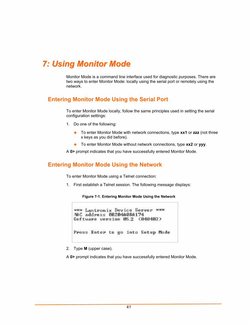
To enter Monitor Mode using a Telnet connection:
1. First establish a Telnet session. The following message displays:
Figure 7-1. Entering Monitor Mode Using the Network
2. Type M (upper case).
A 0> prompt indicates that you have successfully entered Monitor Mode.
Using Monitor Mode UDS200 User Guide
42
Using Monitor Mode Commands
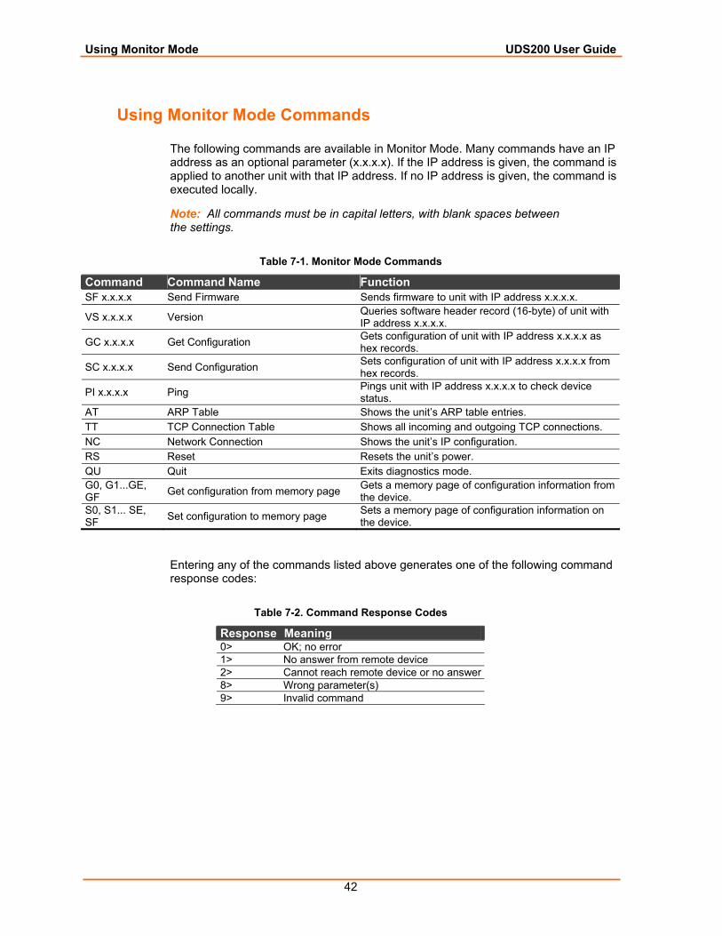
The following commands are available in Monitor Mode. Many commands have an IP address as an optional parameter (x.x.x.x). If the IP address is given, the command is applied to another unit with that IP address. If no IP address is given, the command is executed locally.
Note: All commands must be in capital letters, with blank spaces between the settings.
Table 7-1. Monitor Mode Commands
Command Command Name Function SF x.x.x.x Send Firmware Sends firmware to unit with IP address x.x.x.x.
VS x.x.x.x Version Queries software header record (16-byte) of unit with IP address x.x.x.x.
GC x.x.x.x Get Configuration Gets configuration of unit with IP address x.x.x.x as hex records.
SC x.x.x.x Send Configuration Sets configuration of unit with IP address x.x.x.x from hex records.
PI x.x.x.x Ping Pings unit with IP address x.x.x.x to check device status.
AT ARP Table Shows the unit’s ARP table entries. TT TCP Connection Table Shows all incoming and outgoing TCP connections. NC Network Connection Shows the unit’s IP configuration. RS Reset Resets the unit’s power. QU Quit Exits diagnostics mode. G0, G1...GE, GF Get configuration from memory page Gets a memory page of configuration information from
the device. S0, S1... SE, SF Set configuration to memory page Sets a memory page of configuration information on
the device.
Entering any of the commands listed above generates one of the following command response codes:
Table 7-2. Command Response Codes
Response Meaning 0> OK; no error 1> No answer from remote device 2> Cannot reach remote device or no answer8> Wrong parameter(s) 9> Invalid command
43
88:: TTrroouubblleesshhoooottiinngg aanndd TTeecchhnniiccaall SSuuppppoorrtt This chapter discusses how you can diagnose and fix errors quickly without having to contact a dealer or Lantronix.
It helps to connect a terminal to the serial port while diagnosing an error to view summary messages that may display. When troubleshooting, always ensure that the physical connections (power cable, network cable, and serial cable) are secure.
Note: Some unexplained errors might be caused by duplicate IP addresses on the network. Make sure that your unit's IP address is unique.
LEDs
The UDS200 contains the following LEDs, which may help you diagnose problems.
Power
10 Mbps Link/Activity (green)
100 Mbps Link/Activity (green)
Diagnostics (red)
Status Channel 1 (green)
Status Channel 2 (green)
Simultaneously lit red and green LEDs mean something is wrong. If the red LED is lit or blinking, count the number of times the green LED blinks between its pauses. The following table explains the LED functions:
Troubleshooting and Technical Support UDS200 User Guide
44
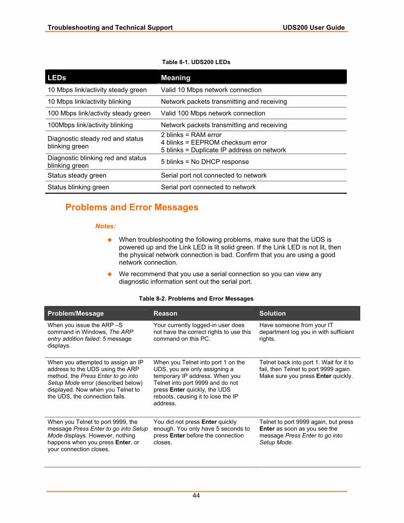
Table 8-1. UDS200 LEDs
LEDs Meaning 10 Mbps link/activity steady green Valid 10 Mbps network connection
10 Mbps link/activity blinking Network packets transmitting and receiving
100 Mbps link/activity steady green Valid 100 Mbps network connection
100Mbps link/activity blinking Network packets transmitting and receiving
Diagnostic steady red and status blinking green
2 blinks = RAM error 4 blinks = EEPROM checksum error 5 blinks = Duplicate IP address on network
Diagnostic blinking red and status blinking green 5 blinks = No DHCP response
Status steady green Serial port not connected to network
Status blinking green Serial port connected to network
Problems and Error Messages
Notes:
When troubleshooting the following problems, make sure that the UDS is powered up and the Link LED is lit solid green. If the Link LED is not lit, then the physical network connection is bad. Confirm that you are using a good network connection.
We recommend that you use a serial connection so you can view any diagnostic information sent out the serial port.
Table 8-2. Problems and Error Messages
Problem/Message Reason Solution When you issue the ARP –S command in Windows, The ARP entry addition failed: 5 message displays.
Your currently logged-in user does not have the correct rights to use this command on this PC.
Have someone from your IT department log you in with sufficient rights.
When you attempted to assign an IP address to the UDS using the ARP method, the Press Enter to go into Setup Mode error (described below) displayed. Now when you Telnet to the UDS, the connection fails.
When you Telnet into port 1 on the UDS, you are only assigning a temporary IP address. When you Telnet into port 9999 and do not press Enter quickly, the UDS reboots, causing it to lose the IP address.
Telnet back into port 1. Wait for it to fail, then Telnet to port 9999 again. Make sure you press Enter quickly.
When you Telnet to port 9999, the message Press Enter to go into Setup Mode displays. However, nothing happens when you press Enter, or your connection closes.
You did not press Enter quickly enough. You only have 5 seconds to press Enter before the connection closes.
Telnet to port 9999 again, but press Enter as soon as you see the message Press Enter to go into Setup Mode.
Troubleshooting and Technical Support UDS200 User Guide
45
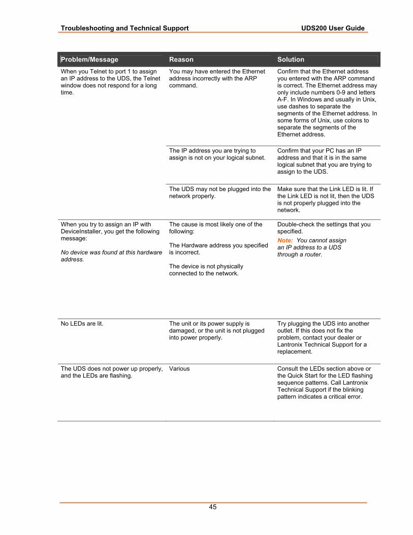
Problem/Message Reason Solution You may have entered the Ethernet address incorrectly with the ARP command.
Confirm that the Ethernet address you entered with the ARP command is correct. The Ethernet address may only include numbers 0-9 and letters A-F. In Windows and usually in Unix, use dashes to separate the segments of the Ethernet address. In some forms of Unix, use colons to separate the segments of the Ethernet address.
The IP address you are trying to assign is not on your logical subnet.
Confirm that your PC has an IP address and that it is in the same logical subnet that you are trying to assign to the UDS.
When you Telnet to port 1 to assign an IP address to the UDS, the Telnet window does not respond for a long time.
The UDS may not be plugged into the network properly.
Make sure that the Link LED is lit. If the Link LED is not lit, then the UDS is not properly plugged into the network.
When you try to assign an IP with DeviceInstaller, you get the following message: No device was found at this hardware address.
The cause is most likely one of the following: The Hardware address you specified is incorrect. The device is not physically connected to the network.
Double-check the settings that you specified. Note: You cannot assign an IP address to a UDS through a router.
No LEDs are lit. The unit or its power supply is damaged, or the unit is not plugged into power properly.
Try plugging the UDS into another outlet. If this does not fix the problem, contact your dealer or Lantronix Technical Support for a replacement.
The UDS does not power up properly, and the LEDs are flashing.
Various Consult the LEDs section above or the Quick Start for the LED flashing sequence patterns. Call Lantronix Technical Support if the blinking pattern indicates a critical error.
Troubleshooting and Technical Support UDS200 User Guide
46
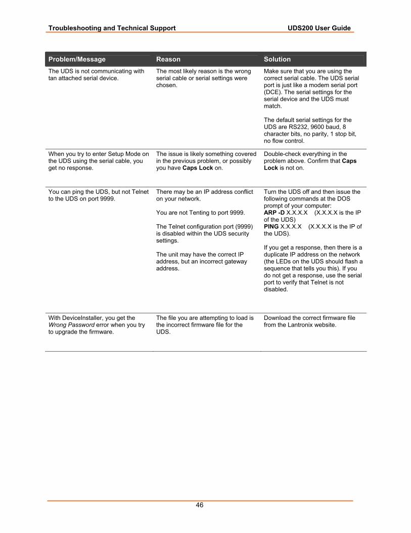
Problem/Message Reason Solution The UDS is not communicating with tan attached serial device.
The most likely reason is the wrong serial cable or serial settings were chosen.
Make sure that you are using the correct serial cable. The UDS serial port is just like a modem serial port (DCE). The serial settings for the serial device and the UDS must match. The default serial settings for the UDS are RS232, 9600 baud, 8 character bits, no parity, 1 stop bit, no flow control.
When you try to enter Setup Mode on the UDS using the serial cable, you get no response.
The issue is likely something covered in the previous problem, or possibly you have Caps Lock on.
Double-check everything in the problem above. Confirm that Caps Lock is not on.
You can ping the UDS, but not Telnet to the UDS on port 9999.
There may be an IP address conflict on your network. You are not Tenting to port 9999. The Telnet configuration port (9999) is disabled within the UDS security settings. The unit may have the correct IP address, but an incorrect gateway address.
Turn the UDS off and then issue the following commands at the DOS prompt of your computer: ARP -D X.X.X.X (X.X.X.X is the IP of the UDS) PING X.X.X.X (X.X.X.X is the IP of the UDS). If you get a response, then there is a duplicate IP address on the network (the LEDs on the UDS should flash a sequence that tells you this). If you do not get a response, use the serial port to verify that Telnet is not disabled.
With DeviceInstaller, you get the Wrong Password error when you try to upgrade the firmware.
The file you are attempting to load is the incorrect firmware file for the UDS.
Download the correct firmware file from the Lantronix website.
Troubleshooting and Technical Support UDS200 User Guide
47
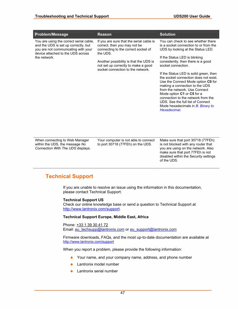
Problem/Message Reason Solution You are using the correct serial cable, and the UDS is set up correctly, but you are not communicating with your device attached to the UDS across the network.
If you are sure that the serial cable is correct, then you may not be connecting to the correct socket of the UDS. Another possibility is that the UDS is not set up correctly to make a good socket connection to the network.
You can check to see whether there is a socket connection to or from the UDS by looking at the Status LED. If the Status LED is blinking consistently, then there is a good socket connection. If the Status LED is solid green, then the socket connection does not exist. Use the Connect Mode option C0 for making a connection to the UDS from the network. Use Connect Mode option C1 or C5 for a connection to the network from the UDS. See the full list of Connect Mode hexadecimals in B: Binary to Hexadecimal.
When connecting to Web Manager within the UDS, the message No Connection With The UDS displays.
Your computer is not able to connect to port 30718 (77FEh) on the UDS.
Make sure that port 30718 (77FEh) is not blocked with any router that you are using on the network. Also make sure that port 77FEh is not disabled within the Security settings of the UDS.
Technical Support
If you are unable to resolve an issue using the information in this documentation, please contact Technical Support:
Technical Support US Check our online knowledge base or send a question to Technical Support at http://www.lantronix.com/support.
Technical Support Europe, Middle East, Africa
Phone: +33 1 39 30 41 72 Email: [email protected] or [email protected]
Firmware downloads, FAQs, and the most up-to-date documentation are available at http://www.lantronix.com/support
When you report a problem, please provide the following information:
Your name, and your company name, address, and phone number
Lantronix model number
Lantronix serial number

Troubleshooting and Technical Support UDS200 User Guide
48
Software version (on the first screen shown when you Telnet to the device and type show)
Description of the problem
Debug report (stack dump), if applicable
Status of the unit when the problem occurred (please try to include information on user and network activity at the time of the problem)
49
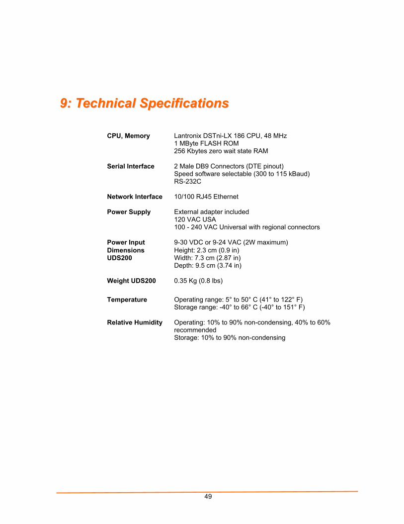
99:: TTeecchhnniiccaall SSppeecciiffiiccaattiioonnss
CPU, Memory Lantronix DSTni-LX 186 CPU, 48 MHz 1 MByte FLASH ROM 256 Kbytes zero wait state RAM
Serial Interface
2 Male DB9 Connectors (DTE pinout) Speed software selectable (300 to 115 kBaud) RS-232C
Network Interface
10/100 RJ45 Ethernet
Power Supply External adapter included 120 VAC USA 100 - 240 VAC Universal with regional connectors
Power Input 9-30 VDC or 9-24 VAC (2W maximum) Dimensions UDS200
Height: 2.3 cm (0.9 in) Width: 7.3 cm (2.87 in) Depth: 9.5 cm (3.74 in)
Weight UDS200 0.35 Kg (0.8 lbs)
Temperature
Operating range: 5° to 50° C (41° to 122° F) Storage range: -40° to 66° C (-40° to 151° F)
Relative Humidity Operating: 10% to 90% non-condensing, 40% to 60% recommended Storage: 10% to 90% non-condensing
50
1100:: CCoonnnneeccttiioonnss aanndd PPiinnoouuttss
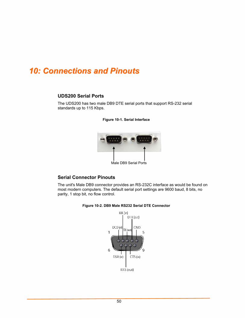
UDS200 Serial Ports The UDS200 has two male DB9 DTE serial ports that support RS-232 serial standards up to 115 Kbps.
Figure 10-1. Serial Interface
Serial Connector Pinouts The unit's Male DB9 connector provides an RS-232C interface as would be found on most modern computers. The default serial port settings are 9600 baud, 8 bits, no parity, 1 stop bit, no flow control.
Figure 10-2. DB9 Male RS232 Serial DTE Connector
Male DB9 Serial Ports
UDS200 User Guide Connections and Pinouts
51
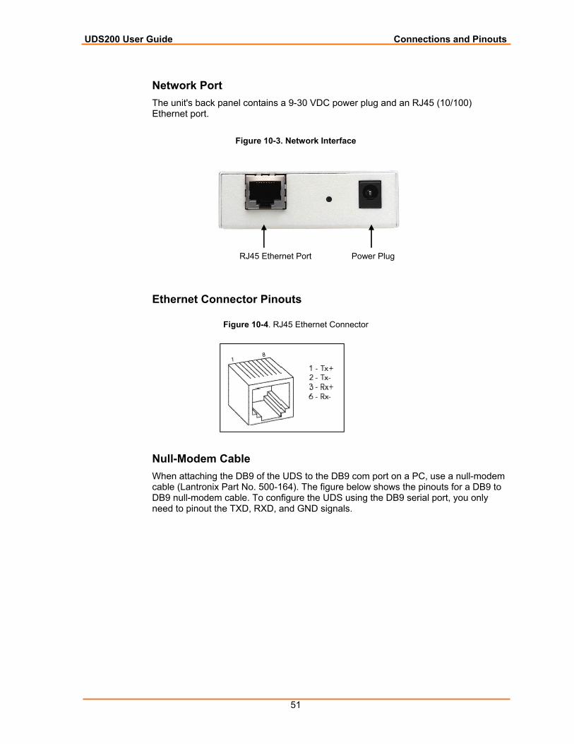
Network Port The unit's back panel contains a 9-30 VDC power plug and an RJ45 (10/100) Ethernet port.
Figure 10-3. Network Interface
Ethernet Connector Pinouts
Figure 10-4. RJ45 Ethernet Connector
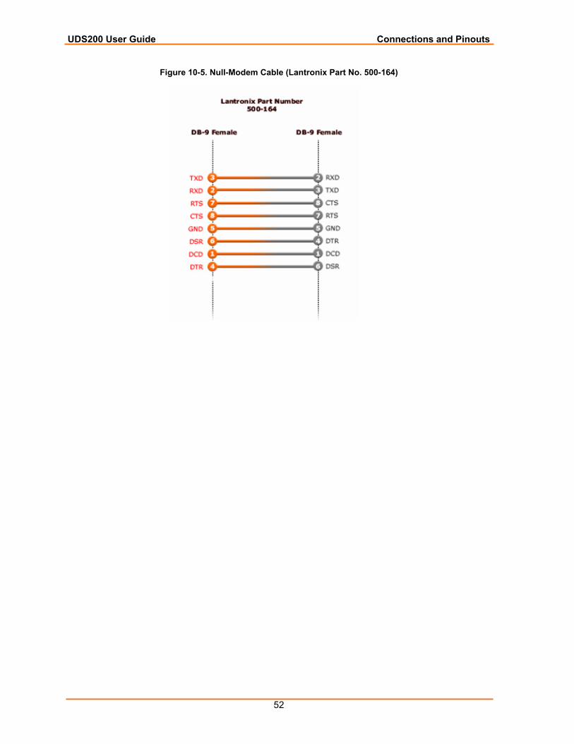
Null-Modem Cable When attaching the DB9 of the UDS to the DB9 com port on a PC, use a null-modem cable (Lantronix Part No. 500-164). The figure below shows the pinouts for a DB9 to DB9 null-modem cable. To configure the UDS using the DB9 serial port, you only need to pinout the TXD, RXD, and GND signals.
RJ45 Ethernet Port Power Plug
UDS200 User Guide Connections and Pinouts
52
Figure 10-5. Null-Modem Cable (Lantronix Part No. 500-164)
53
AA:: AAlltteerrnnaattiivvee WWaayyss ttoo AAssssiiggnn aann IIPP AAddddrreessss Earlier chapters describe how to assign a static IP address using DeviceInstaller, Web Manager, and Setup Mode (through a Telnet or serial connection). This section covers other methods for assigning an IP address over the network.
DHCP The unit ships with a default IP address of 0.0.0.0, which automatically enables DHCP. If a DHCP server exists on the network, it provides the unit with an IP address, gateway address, and subnet mask when the unit boots up.
You can use the DeviceInstaller software to search the network for the DHCP-assigned IP address and add it to the list of devices retrieved.
Note: This DHCP address does not appear in the unit’s Setup Mode or in Web Manager. You can determine your unit’s DHCP-assigned IP address in Monitor Mode. When you enter Monitor Mode from the serial port with network connection enabled and issue the NC (Network Communication) command, you see the unit’s IP configuration.
AutoIP The unit ships with a default IP address of 0.0.0.0, which automatically enables Auto IP within the unit. AutoIP is an alternative to DHCP that allows hosts to obtain an IP address automatically in smaller networks that may not have a DHCP server. A range of IP addresses (from 169.254.0.1 to 169.254.255.1) has been explicitly reserved for AutoIP-enabled devices. Do not use this range of Auto IP addresses over the Internet.
If your unit cannot find a DHCP server, and you have not manually assigned an IP address to it, the unit automatically selects an address from the AutoIP reserved range. Then, your unit sends out a (ARP) request to other nodes on the same network to see whether the selected address is being used.
If the selected address is not in use, then the unit uses it for local subnet communication.
If another device is using the selected IP address, the unit selects another address from the AutoIP range and reboots. After reboot, the unit sends out another ARP request to see if the selected address is in use, and so on.
AutoIP does not replace DHCP. The unit continues to look for a DHCP server on the network. If it finds a DHCP server, the unit switches to the DHCP server-provided address and reboots.
Note: If the unit finds a DHCP server, but the server denies the request for an IP address, the unit does not attach to the network, but waits and retries.
Alternative Ways to Assign an IP Address UDS200 User Guide
54
You can disable AutoIP by setting the unit’s IP address to 0.0.1.0. This setting enables DHCP but disables AutoIP.
BOOTP Similar to DHCP, but for smaller networks. Automatically assigns the IP address for a specific duration of time.
ARP and Telnet If the unit has no IP address, you can use Address Resolution Protocol (ARP) method from UNIX and Windows-based systems to assign a temporary IP address.
To assign a temporary IP address:
1. On a UNIX or Windows-based host, create an entry in the host's ARP table using the intended IP address and the hardware address of the unit (on the product label on the bottom of the unit).
arp -s 191.12.3.77 00:20:4a:xx:xx:xx
Note: For the ARP command to work on Windows 95, the ARP table on the PC must have at least one IP address defined other than its own.
2. If you are using Windows 95, type ARP -A at the DOS command prompt to verify that there is at least one entry in the ARP table. If the local machine is the only entry, ping another IP address on your network to build a new entry in the ARP table; the IP address must be a host other than the machine on which you are working. Once there is at least one additional entry in the ARP table, use the following command to ARP an IP address to the unit:
arp -s 191.12.3.77 00-20-4a-xx-xx-xx
3. Open a Telnet connection to port 1. The connection fails quickly, but the unit temporarily changes its IP address to the one designated in this step.
telnet 191.12.3.77 1 4. Open a Telnet connection to port 9999, and press Enter within five seconds
to go into Setup Mode. If you wait longer than five seconds, the unit reboots. telnet 191.12.3.77 9999
Note: The IP address you just set is temporary and reverts to the default value when the unit’s power is reset, unless you configure the unit with a static IP address and store the changes permanently.
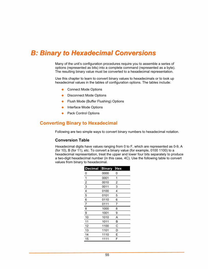
55
BB:: BBiinnaarryy ttoo HHeexxaaddeecciimmaall CCoonnvveerrssiioonnss Many of the unit’s configuration procedures require you to assemble a series of options (represented as bits) into a complete command (represented as a byte). The resulting binary value must be converted to a hexadecimal representation.
Use this chapter to learn to convert binary values to hexadecimals or to look up hexadecimal values in the tables of configuration options. The tables include:
Connect Mode Options
Disconnect Mode Options
Flush Mode (Buffer Flushing) Options
Interface Mode Options
Pack Control Options
Converting Binary to Hexadecimal
Following are two simple ways to convert binary numbers to hexadecimal notation.
Conversion Table Hexadecimal digits have values ranging from 0 to F, which are represented as 0-9, A (for 10), B (for 11), etc. To convert a binary value (for example, 0100 1100) to a hexadecimal representation, treat the upper and lower four bits separately to produce a two-digit hexadecimal number (in this case, 4C). Use the following table to convert values from binary to hexadecimal.
Decimal Binary Hex 0 0000 0 1 0001 1 2 0010 2 3 0011 3 4 0100 4 5 0101 5 6 0110 6 7 0111 7 8 1000 8 9 1001 9 10 1010 A 11 1011 B 12 1100 C 13 1101 D 14 1110 E 15 1111 F
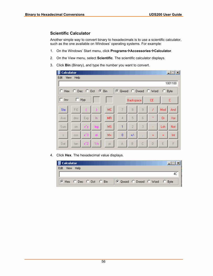
Binary to Hexadecimal Conversions UDS200 User Guide
56
Scientific Calculator Another simple way to convert binary to hexadecimals is to use a scientific calculator, such as the one available on Windows’ operating systems. For example:
1. On the Windows’ Start menu, click Programs Accessories Calculator.
2. On the View menu, select Scientific. The scientific calculator displays.
3. Click Bin (Binary), and type the number you want to convert.
4. Click Hex. The hexadecimal value displays.
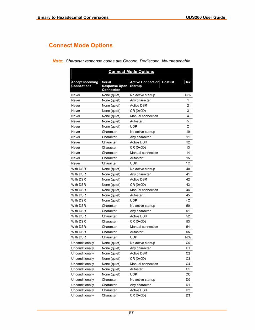
Binary to Hexadecimal Conversions UDS200 User Guide
57
Connect Mode Options
Note: Character response codes are C=conn, D=disconn, N=unreachable
Connect Mode Options
Accept Incoming Connections
Serial Response Upon Connection
Active Connection Startup
Hostlist Hex
Never None (quiet) No active startup N/A Never None (quiet) Any character 1 Never None (quiet) Active DSR 2 Never None (quiet) CR (0x0D) 3 Never None (quiet) Manual connection 4 Never None (quiet) Autostart 5 Never None (quiet) UDP C Never Character No active startup 10 Never Character Any character 11 Never Character Active DSR 12 Never Character CR (0x0D) 13 Never Character Manual connection 14 Never Character Autostart 15 Never Character UDP 1C
With DSR None (quiet) No active startup 40 With DSR None (quiet) Any character 41 With DSR None (quiet) Active DSR 42 With DSR None (quiet) CR (0x0D) 43 With DSR None (quiet) Manual connection 44 With DSR None (quiet) Autostart 45 With DSR None (quiet) UDP 4C With DSR Character No active startup 50 With DSR Character Any character 51 With DSR Character Active DSR 52 With DSR Character CR (0x0D) 53 With DSR Character Manual connection 54 With DSR Character Autostart 55 With DSR Character UDP N/A
Unconditionally None (quiet) No active startup C0 Unconditionally None (quiet) Any character C1 Unconditionally None (quiet) Active DSR C2 Unconditionally None (quiet) CR (0x0D) C3 Unconditionally None (quiet) Manual connection C4 Unconditionally None (quiet) Autostart C5 Unconditionally None (quiet) UDP CC Unconditionally Character No active startup D0 Unconditionally Character Any character D1 Unconditionally Character Active DSR D2 Unconditionally Character CR (0x0D) D3
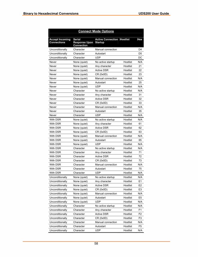
Binary to Hexadecimal Conversions UDS200 User Guide
58
Connect Mode Options
Accept Incoming Connections
Serial Response Upon Connection
Active Connection Startup
Hostlist Hex
Unconditionally Character Manual connection D4 Unconditionally Character Autostart D5 Unconditionally Character UDP DC
Never None (quiet) No active startup Hostlist N/A Never None (quiet) Any character Hostlist 21 Never None (quiet) Active DSR Hostlist 22 Never None (quiet) CR (0x0D) Hostlist 23 Never None (quiet) Manual connection Hostlist N/A Never None (quiet) Autostart Hostlist 25 Never None (quiet) UDP Hostlist N/A Never Character No active startup Hostlist N/A Never Character Any character Hostlist 31 Never Character Active DSR Hostlist 32 Never Character CR (0x0D) Hostlist 33 Never Character Manual connection Hostlist N/A Never Character Autostart Hostlist 35 Never Character UDP Hostlist N/A
With DSR None (quiet) No active startup Hostlist N/A With DSR None (quiet) Any character Hostlist 61 With DSR None (quiet) Active DSR Hostlist 62 With DSR None (quiet) CR (0x0D) Hostlist 63 With DSR None (quiet) Manual connection Hostlist N/A With DSR None (quiet) Autostart Hostlist 65 With DSR None (quiet) UDP Hostlist N/A With DSR Character No active startup Hostlist N/A With DSR Character Any character Hostlist 71 With DSR Character Active DSR Hostlist 72 With DSR Character CR (0x0D) Hostlist 73 With DSR Character Manual connection Hostlist N/A With DSR Character Autostart Hostlist 75 With DSR Character UDP Hostlist N/A
Unconditionally None (quiet) No active startup Hostlist N/A Unconditionally None (quiet) Any character Hostlist E1 Unconditionally None (quiet) Active DSR Hostlist E2 Unconditionally None (quiet) CR (0x0D) Hostlist E3 Unconditionally None (quiet) Manual connection Hostlist N/A Unconditionally None (quiet) Autostart Hostlist E5 Unconditionally None (quiet) UDP Hostlist N/A Unconditionally Character No active startup Hostlist N/A Unconditionally Character Any character Hostlist F1 Unconditionally Character Active DSR Hostlist F2 Unconditionally Character CR (0x0D) Hostlist F3 Unconditionally Character Manual connection Hostlist N/A Unconditionally Character Autostart Hostlist F5 Unconditionally Character UDP Hostlist N/A
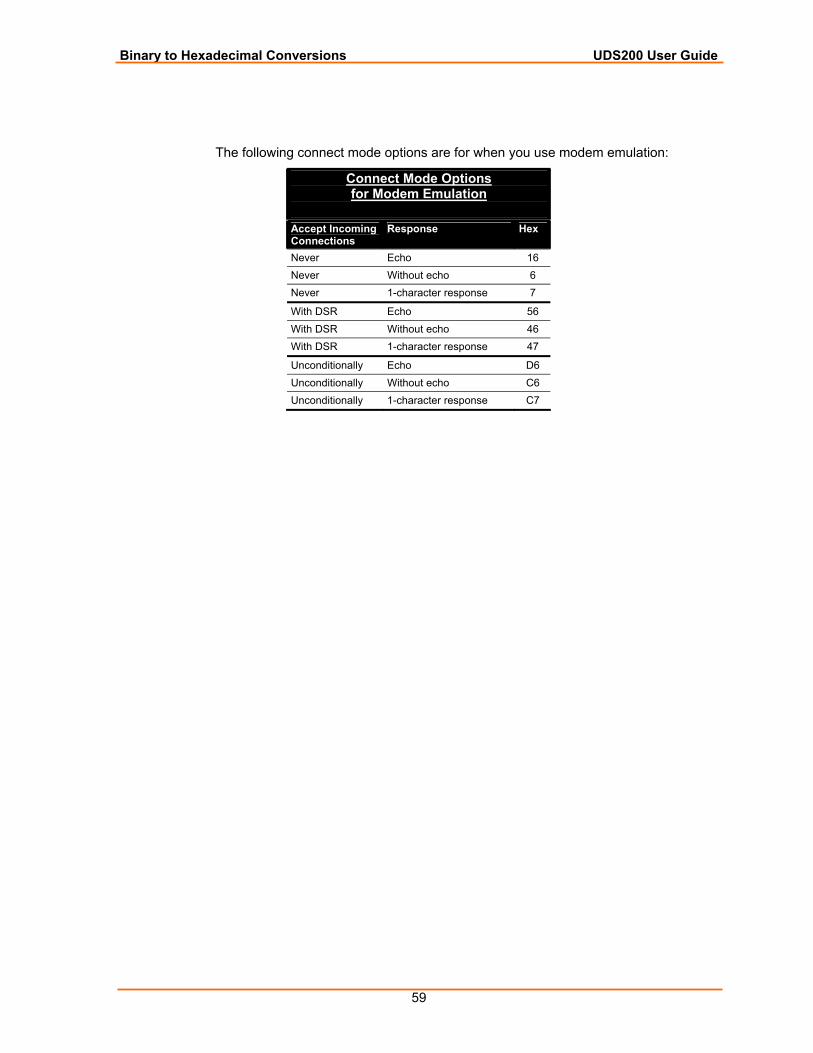
Binary to Hexadecimal Conversions UDS200 User Guide
59
The following connect mode options are for when you use modem emulation:
Connect Mode Options for Modem Emulation
Accept Incoming Connections
Response Hex
Never Echo 16 Never Without echo 6 Never 1-character response 7
With DSR Echo 56 With DSR Without echo 46 With DSR 1-character response 47
Unconditionally Echo D6 Unconditionally Without echo C6 Unconditionally 1-character response C7
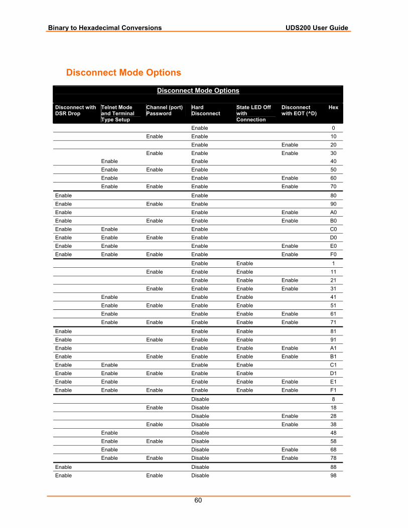
Binary to Hexadecimal Conversions UDS200 User Guide
60
Disconnect Mode Options
Disconnect Mode Options
Disconnect with DSR Drop
Telnet Mode and Terminal Type Setup
Channel (port) Password
Hard Disconnect
State LED Off with Connection
Disconnect with EOT (^D)
Hex
Enable 0 Enable Enable 10 Enable Enable 20 Enable Enable Enable 30 Enable Enable 40 Enable Enable Enable 50 Enable Enable Enable 60 Enable Enable Enable Enable 70
Enable Enable 80 Enable Enable Enable 90 Enable Enable Enable A0 Enable Enable Enable Enable B0 Enable Enable Enable C0 Enable Enable Enable Enable D0 Enable Enable Enable Enable E0 Enable Enable Enable Enable Enable F0
Enable Enable 1 Enable Enable Enable 11 Enable Enable Enable 21 Enable Enable Enable Enable 31 Enable Enable Enable 41 Enable Enable Enable Enable 51 Enable Enable Enable Enable 61 Enable Enable Enable Enable Enable 71
Enable Enable Enable 81 Enable Enable Enable Enable 91 Enable Enable Enable Enable A1 Enable Enable Enable Enable Enable B1 Enable Enable Enable Enable C1 Enable Enable Enable Enable Enable D1 Enable Enable Enable Enable Enable E1 Enable Enable Enable Enable Enable Enable F1
Disable 8 Enable Disable 18 Disable Enable 28 Enable Disable Enable 38 Enable Disable 48 Enable Enable Disable 58 Enable Disable Enable 68 Enable Enable Disable Enable 78
Enable Disable 88 Enable Enable Disable 98
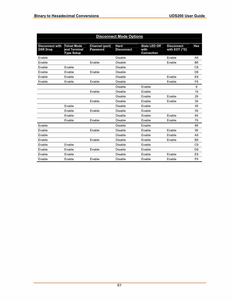
Binary to Hexadecimal Conversions UDS200 User Guide
61
Disconnect Mode Options
Disconnect with DSR Drop
Telnet Mode and Terminal Type Setup
Channel (port) Password
Hard Disconnect
State LED Off with Connection
Disconnect with EOT (^D)
Hex
Enable Disable Enable A8 Enable Enable Disable Enable B8 Enable Enable Disable C8 Enable Enable Enable Disable D8 Enable Enable Disable Enable E8 Enable Enable Enable Disable Enable F8
Disable Enable 9 Enable Disable Enable 19 Disable Enable Enable 29 Enable Disable Enable Enable 39 Enable Disable Enable 49 Enable Enable Disable Enable 59 Enable Disable Enable Enable 69 Enable Enable Disable Enable Enable 79
Enable Disable Enable 89 Enable Enable Disable Enable Enable 99 Enable Disable Enable Enable A9 Enable Enable Disable Enable Enable B9 Enable Enable Disable Enable C9 Enable Enable Enable Disable Enable D9 Enable Enable Disable Enable Enable E9 Enable Enable Enable Disable Enable Enable F9
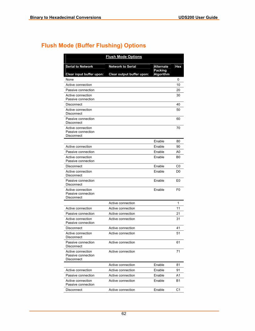
Binary to Hexadecimal Conversions UDS200 User Guide
62
Flush Mode (Buffer Flushing) Options
Flush Mode Options
Serial to Network Clear input buffer upon:
Network to Serial Clear output buffer upon:
Alternate Packing Algorithm
Hex
None 0 Active connection 10 Passive connection 20 Active connection Passive connection
30
Disconnect 40 Active connection Disconnect
50
Passive connection Disconnect
60
Active connection Passive connection Disconnect
70
Enable 80 Active connection Enable 90 Passive connection Enable A0 Active connection Passive connection
Enable B0
Disconnect Enable C0 Active connection Disconnect
Enable D0
Passive connection Disconnect
Enable E0
Active connection Passive connection Disconnect
Enable F0
Active connection 1 Active connection Active connection 11 Passive connection Active connection 21 Active connection Passive connection
Active connection 31
Disconnect Active connection 41 Active connection Disconnect
Active connection 51
Passive connection Disconnect
Active connection 61
Active connection Passive connection Disconnect
Active connection 71
Active connection Enable 81 Active connection Active connection Enable 91 Passive connection Active connection Enable A1 Active connection Passive connection
Active connection Enable B1
Disconnect Active connection Enable C1
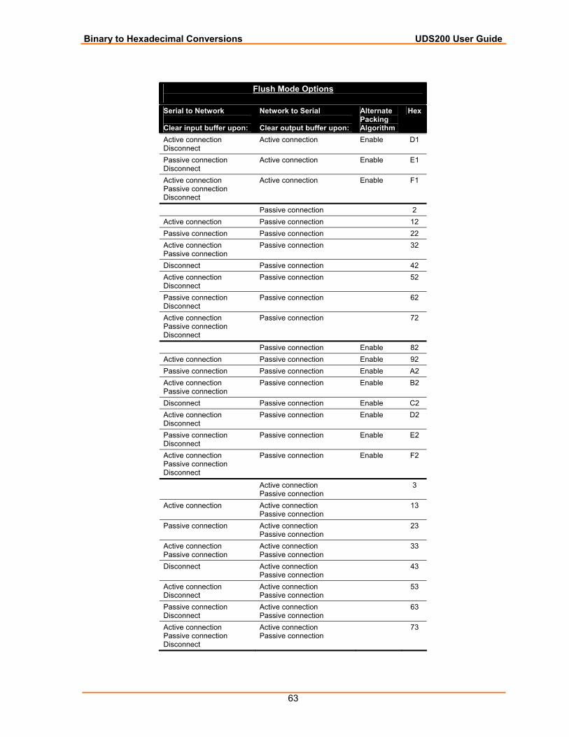
Binary to Hexadecimal Conversions UDS200 User Guide
63
Flush Mode Options
Serial to Network Clear input buffer upon:
Network to Serial Clear output buffer upon:
Alternate Packing Algorithm
Hex
Active connection Disconnect
Active connection Enable D1
Passive connection Disconnect
Active connection Enable E1
Active connection Passive connection Disconnect
Active connection Enable F1
Passive connection 2 Active connection Passive connection 12 Passive connection Passive connection 22 Active connection Passive connection
Passive connection 32
Disconnect Passive connection 42 Active connection Disconnect
Passive connection 52
Passive connection Disconnect
Passive connection 62
Active connection Passive connection Disconnect
Passive connection 72
Passive connection Enable 82 Active connection Passive connection Enable 92 Passive connection Passive connection Enable A2 Active connection Passive connection
Passive connection Enable B2
Disconnect Passive connection Enable C2 Active connection Disconnect
Passive connection Enable D2
Passive connection Disconnect
Passive connection Enable E2
Active connection Passive connection Disconnect
Passive connection Enable F2
Active connection Passive connection
3
Active connection Active connection Passive connection
13
Passive connection Active connection Passive connection
23
Active connection Passive connection
Active connection Passive connection
33
Disconnect Active connection Passive connection
43
Active connection Disconnect
Active connection Passive connection
53
Passive connection Disconnect
Active connection Passive connection
63
Active connection Passive connection Disconnect
Active connection Passive connection
73
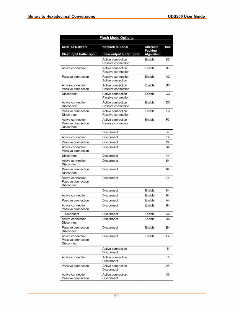
Binary to Hexadecimal Conversions UDS200 User Guide
64
Flush Mode Options
Serial to Network Clear input buffer upon:
Network to Serial Clear output buffer upon:
Alternate Packing Algorithm
Hex
Active connection Passive connection
Enable 83
Active connection Active connection Passive connection
Enable 93
Passive connection Passive connection Active connection
Enable A3
Active connection Passive connection
Active connection Passive connection
Enable B3
Disconnect Active connection Passive connection
Enable C3
Active connection Disconnect
Active connection Passive connection
Enable D3
Passive connection Disconnect
Active connection Passive connection
Enable E3
Active connection Passive connection Disconnect
Active connection Passive connection
Enable F3
Disconnect 4 Active connection Disconnect 14 Passive connection Disconnect 24 Active connection Passive connection
Disconnect 34
Disconnect Disconnect 44 Active connection Disconnect
Disconnect 54
Passive connection Disconnect
Disconnect 64
Active connection Passive connection Disconnect
Disconnect 74
Disconnect Enable 84 Active connection Disconnect Enable 94 Passive connection Disconnect Enable A4 Active connection Passive connection
Disconnect Enable B4
Disconnect Disconnect Enable C4 Active connection Disconnect
Disconnect Enable D4
Passive connection Disconnect
Disconnect Enable E4
Active connection Passive connection Disconnect
Disconnect Enable F4
Active connection Disconnect
5
Active connection Active connection Disconnect
15
Passive connection Active connection Disconnect
25
Active connection Passive connection
Active connection Disconnect
35
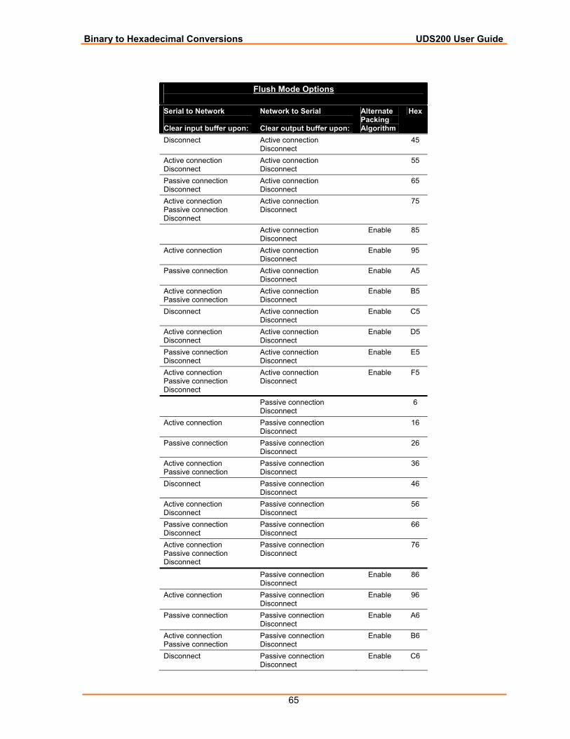
Binary to Hexadecimal Conversions UDS200 User Guide
65
Flush Mode Options
Serial to Network Clear input buffer upon:
Network to Serial Clear output buffer upon:
Alternate Packing Algorithm
Hex
Disconnect Active connection Disconnect
45
Active connection Disconnect
Active connection Disconnect
55
Passive connection Disconnect
Active connection Disconnect
65
Active connection Passive connection Disconnect
Active connection Disconnect
75
Active connection Disconnect
Enable 85
Active connection Active connection Disconnect
Enable 95
Passive connection Active connection Disconnect
Enable A5
Active connection Passive connection
Active connection Disconnect
Enable B5
Disconnect Active connection Disconnect
Enable C5
Active connection Disconnect
Active connection Disconnect
Enable D5
Passive connection Disconnect
Active connection Disconnect
Enable E5
Active connection Passive connection Disconnect
Active connection Disconnect
Enable F5
Passive connection Disconnect
6
Active connection Passive connection Disconnect
16
Passive connection Passive connection Disconnect
26
Active connection Passive connection
Passive connection Disconnect
36
Disconnect Passive connection Disconnect
46
Active connection Disconnect
Passive connection Disconnect
56
Passive connection Disconnect
Passive connection Disconnect
66
Active connection Passive connection Disconnect
Passive connection Disconnect
76
Passive connection Disconnect
Enable 86
Active connection Passive connection Disconnect
Enable 96
Passive connection Passive connection Disconnect
Enable A6
Active connection Passive connection
Passive connection Disconnect
Enable B6
Disconnect Passive connection Disconnect
Enable C6
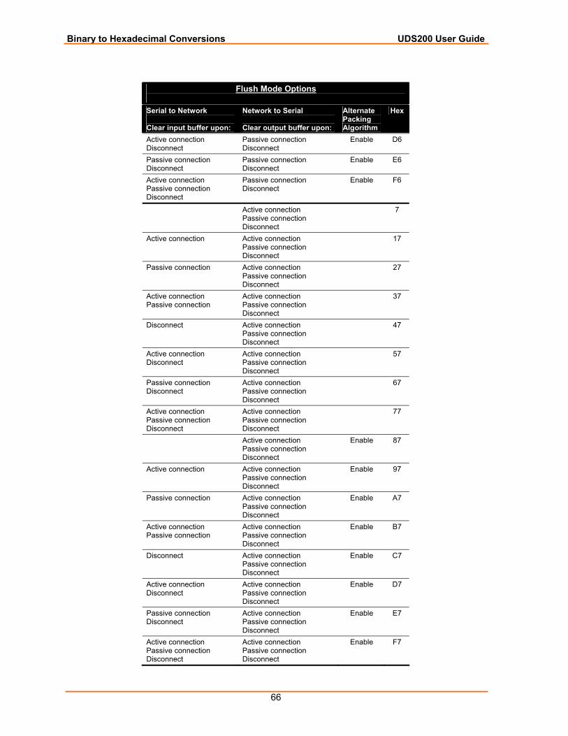
Binary to Hexadecimal Conversions UDS200 User Guide
66
Flush Mode Options
Serial to Network Clear input buffer upon:
Network to Serial Clear output buffer upon:
Alternate Packing Algorithm
Hex
Active connection Disconnect
Passive connection Disconnect
Enable D6
Passive connection Disconnect
Passive connection Disconnect
Enable E6
Active connection Passive connection Disconnect
Passive connection Disconnect
Enable F6
Active connection Passive connection Disconnect
7
Active connection Active connection Passive connection Disconnect
17
Passive connection Active connection Passive connection Disconnect
27
Active connection Passive connection
Active connection Passive connection Disconnect
37
Disconnect Active connection Passive connection Disconnect
47
Active connection Disconnect
Active connection Passive connection Disconnect
57
Passive connection Disconnect
Active connection Passive connection Disconnect
67
Active connection Passive connection Disconnect
Active connection Passive connection Disconnect
77
Active connection Passive connection Disconnect
Enable 87
Active connection Active connection Passive connection Disconnect
Enable 97
Passive connection Active connection Passive connection Disconnect
Enable A7
Active connection Passive connection
Active connection Passive connection Disconnect
Enable B7
Disconnect Active connection Passive connection Disconnect
Enable C7
Active connection Disconnect
Active connection Passive connection Disconnect
Enable D7
Passive connection Disconnect
Active connection Passive connection Disconnect
Enable E7
Active connection Passive connection Disconnect
Active connection Passive connection Disconnect
Enable F7
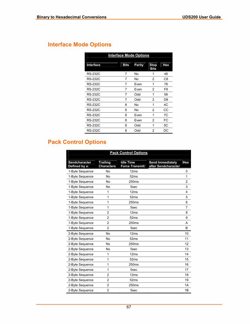
Binary to Hexadecimal Conversions UDS200 User Guide
67
Interface Mode Options
Interface Mode Options
Interface Bits Parity Stop Bits
Hex
RS-232C 7 No 1 48 RS-232C 7 No 2 C8 RS-232C 7 Even 1 78 RS-232C 7 Even 2 F8 RS-232C 7 Odd 1 58 RS-232C 7 Odd 2 D8 RS-232C 8 No 1 4C RS-232C 8 No 2 CC RS-232C 8 Even 1 7C RS-232C 8 Even 2 FC RS-232C 8 Odd 1 5C RS-232C 8 Odd 2 DC
Pack Control Options
Pack Control Options
Sendcharacter Defined by a:
Trailing Characters
Idle Time Force Transmit:
Send Immediately after Sendcharacter
Hex
1-Byte Sequence No 12ms 0 1-Byte Sequence No 52ms 1 1-Byte Sequence No 250ms 2 1-Byte Sequence No 5sec 3 1-Byte Sequence 1 12ms 4 1-Byte Sequence 1 52ms 5 1-Byte Sequence 1 250ms 6 1-Byte Sequence 1 5sec 7 1-Byte Sequence 2 12ms 8 1-Byte Sequence 2 52ms 9 1-Byte Sequence 2 250ms A 1-Byte Sequence 2 5sec B
2-Byte Sequence No 12ms 10 2-Byte Sequence No 52ms 11 2-Byte Sequence No 250ms 12 2-Byte Sequence No 5sec 13 2-Byte Sequence 1 12ms 14 2-Byte Sequence 1 52ms 15 2-Byte Sequence 1 250ms 16 2-Byte Sequence 1 5sec 17 2-Byte Sequence 2 12ms 18 2-Byte Sequence 2 52ms 19 2-Byte Sequence 2 250ms 1A 2-Byte Sequence 2 5sec 1B
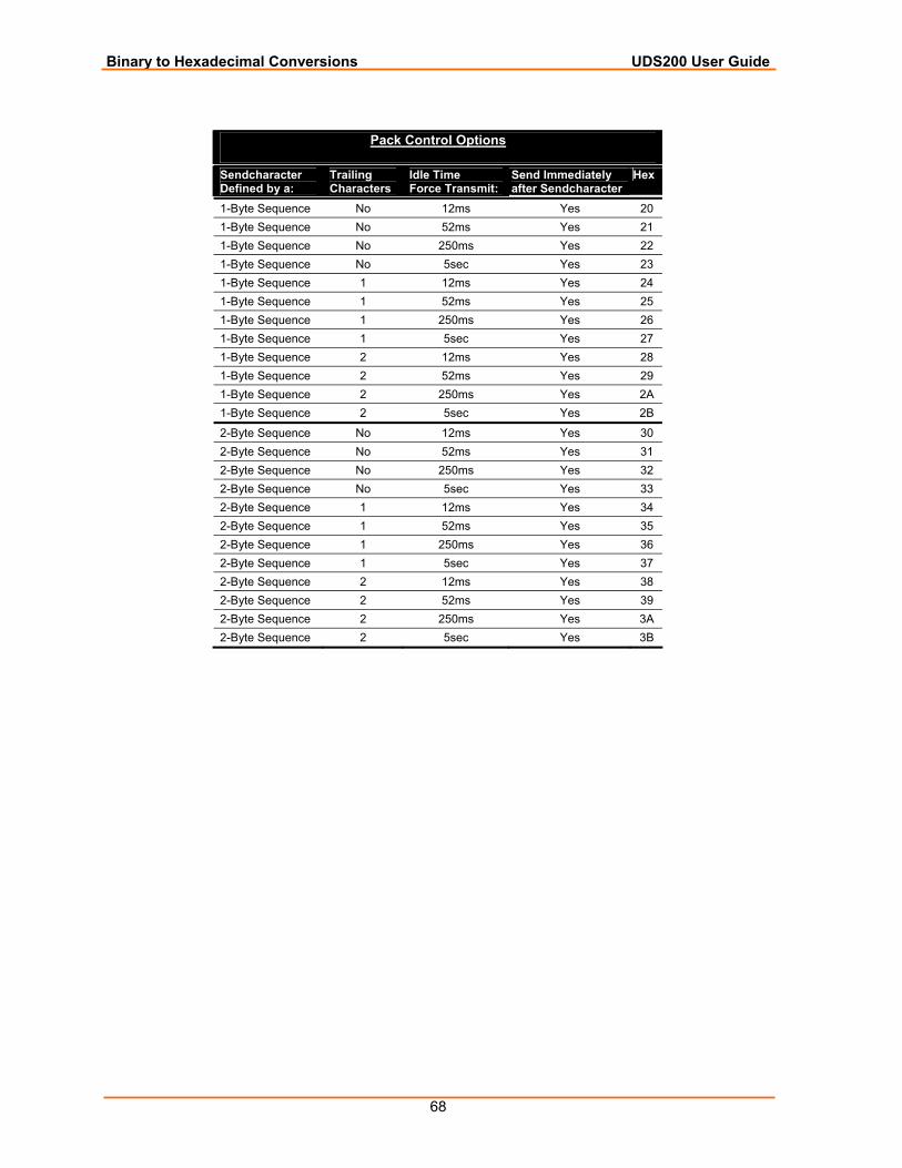
Binary to Hexadecimal Conversions UDS200 User Guide
68
Pack Control Options
Sendcharacter Defined by a:
Trailing Characters
Idle Time Force Transmit:
Send Immediately after Sendcharacter
Hex
1-Byte Sequence No 12ms Yes 20 1-Byte Sequence No 52ms Yes 21 1-Byte Sequence No 250ms Yes 22 1-Byte Sequence No 5sec Yes 23 1-Byte Sequence 1 12ms Yes 24 1-Byte Sequence 1 52ms Yes 25 1-Byte Sequence 1 250ms Yes 26 1-Byte Sequence 1 5sec Yes 27 1-Byte Sequence 2 12ms Yes 28 1-Byte Sequence 2 52ms Yes 29 1-Byte Sequence 2 250ms Yes 2A 1-Byte Sequence 2 5sec Yes 2B
2-Byte Sequence No 12ms Yes 30 2-Byte Sequence No 52ms Yes 31 2-Byte Sequence No 250ms Yes 32 2-Byte Sequence No 5sec Yes 33 2-Byte Sequence 1 12ms Yes 34 2-Byte Sequence 1 52ms Yes 35 2-Byte Sequence 1 250ms Yes 36 2-Byte Sequence 1 5sec Yes 37 2-Byte Sequence 2 12ms Yes 38 2-Byte Sequence 2 52ms Yes 39 2-Byte Sequence 2 250ms Yes 3A 2-Byte Sequence 2 5sec Yes 3B
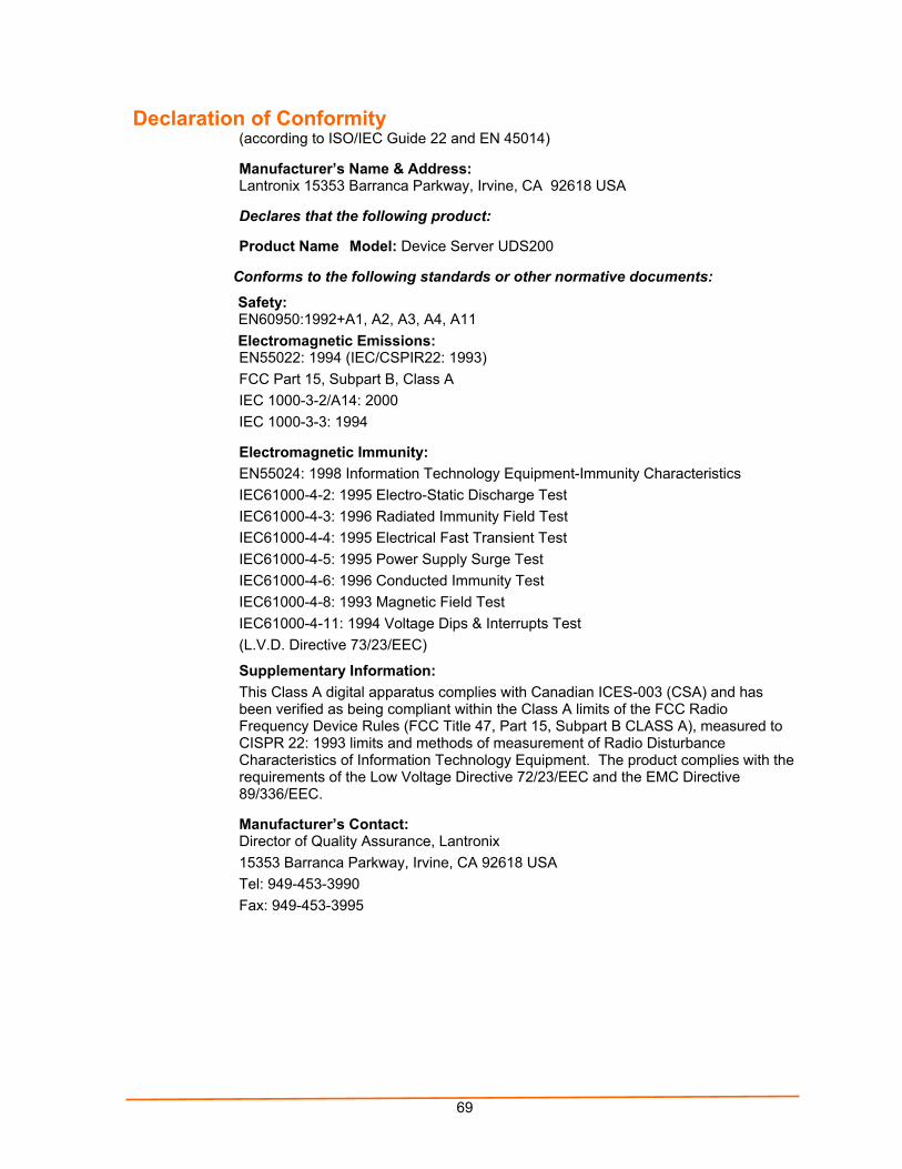
69
Declaration of Conformity (according to ISO/IEC Guide 22 and EN 45014)
Manufacturer’s Name & Address: Lantronix 15353 Barranca Parkway, Irvine, CA 92618 USA
Declares that the following product:
Product Name Model: Device Server UDS200
Conforms to the following standards or other normative documents:
Safety: EN60950:1992+A1, A2, A3, A4, A11 Electromagnetic Emissions: EN55022: 1994 (IEC/CSPIR22: 1993) FCC Part 15, Subpart B, Class A IEC 1000-3-2/A14: 2000 IEC 1000-3-3: 1994
Electromagnetic Immunity: EN55024: 1998 Information Technology Equipment-Immunity Characteristics IEC61000-4-2: 1995 Electro-Static Discharge Test IEC61000-4-3: 1996 Radiated Immunity Field Test IEC61000-4-4: 1995 Electrical Fast Transient Test IEC61000-4-5: 1995 Power Supply Surge Test IEC61000-4-6: 1996 Conducted Immunity Test IEC61000-4-8: 1993 Magnetic Field Test IEC61000-4-11: 1994 Voltage Dips & Interrupts Test (L.V.D. Directive 73/23/EEC)
Supplementary Information: This Class A digital apparatus complies with Canadian ICES-003 (CSA) and has been verified as being compliant within the Class A limits of the FCC Radio Frequency Device Rules (FCC Title 47, Part 15, Subpart B CLASS A), measured to CISPR 22: 1993 limits and methods of measurement of Radio Disturbance Characteristics of Information Technology Equipment. The product complies with the requirements of the Low Voltage Directive 72/23/EEC and the EMC Directive 89/336/EEC.
Manufacturer’s Contact: Director of Quality Assurance, Lantronix 15353 Barranca Parkway, Irvine, CA 92618 USA Tel: 949-453-3990 Fax: 949-453-3995

UDS200 User Guide
70
Warranty For details on the Lantronix warranty policy, go to our web site at www.lantronix.com/support/warranty.
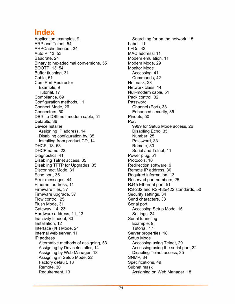
71
Index Application examples, 9 ARP and Telnet, 54 ARPCache timeout, 34 AutoIP, 13, 53 Baudrate, 24 Binary to hexadecimal conversions, 55 BOOTP, 13, 54 Buffer flushing, 31 Cable, 51 Com Port Redirector
Example, 9 Tutorial, 17
Compliance, 69 Configuration methods, 11 Connect Mode, 26 Connectors, 50 DB9- to-DB9 null-modem cable, 51 Defaults, 36 DeviceInstaller
Assigning IP address, 14 Disabling configuration by, 35 Installing from product CD, 14
DHCP, 13, 53 DHCP name, 23 Diagnostics, 41 Disabling Telnet access, 35 Disabling TFTP for Upgrades, 35 Disconnect Mode, 31 Echo port, 35 Error messages, 44 Ethernet address, 11 Firmware files, 37 Firmware upgrade, 37 Flow control, 25 Flush Mode, 31 Gateway, 14, 23 Hardware address, 11, 13 Inactivity timeout, 33 Installation, 12 Interface (I/F) Mode, 24 Internal web server, 11 IP address
Alternative methods of assigning, 53 Assigning by DeviceInstaller, 14 Assigning by Web Manager, 18 Assigning in Setup Mode, 22 Factory default, 13 Remote, 30 Requirement, 13
Searching for on the network, 15 Label, 11 LEDs, 43 MAC address, 11 Modem emulation, 11 Modem Mode, 29 Monitor Mode
Accessing, 41 Commands, 42
Netmask, 23 Network class, 14 Null-modem cable, 51 Pack control, 32 Password
Channel (Port), 33 Enhanced security, 35
Pinouts, 50 Port
9999 for Setup Mode access, 26 Disabling Echo, 35 Number, 25 Password, 33 Remote, 30 Serial and Telnet, 11
Power plug, 51 Protocols, 10 Redirection software, 9 Remote IP address, 30 Required information, 13 Reserved port numbers, 25 RJ45 Ethernet port, 51 RS-232 and RS-485/422 standards, 50 Security settings, 34 Send characters, 33 Serial port
Accessing Setup Mode, 15 Settings, 24
Serial tunneling Example, 9 Tutorial, 17
Server properties, 18 Setup Mode
Accessing using Telnet, 20 Accessing using the serial port, 22 Disabling Telnet access, 35
SNMP, 34 Specifications, 49 Subnet mask
Assigning on Web Manager, 18
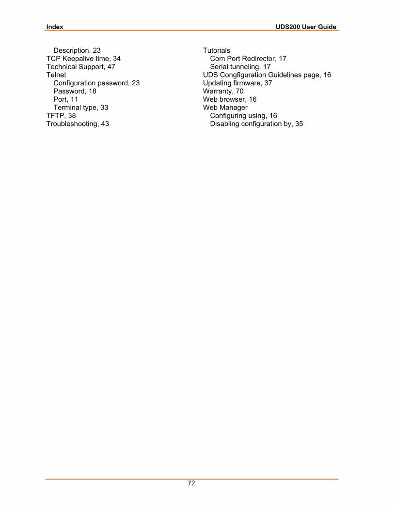
Index UDS200 User Guide
72
Description, 23 TCP Keepalive time, 34 Technical Support, 47 Telnet
Configuration password, 23 Password, 18 Port, 11 Terminal type, 33
TFTP, 38 Troubleshooting, 43
Tutorials Com Port Redirector, 17 Serial tunneling, 17
UDS Congfiguration Guidelines page, 16 Updating firmware, 37 Warranty, 70 Web browser, 16 Web Manager
Configuring using, 16 Disabling configuration by, 35