Embed Size (px)
DESCRIPTION
UDP and TCP. Crash Recovery. The Internet Transport Protocols: UDP. The Internet protocol suite supports a connectionless transport protocol, UDP ( User Datagram Protocol ). - PowerPoint PPT Presentation
Citation preview
UDP and TCP
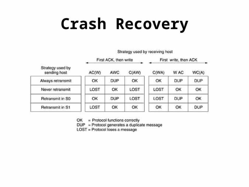
Crash Recovery
The Internet Transport Protocols: UDP
• The Internet protocol suite supports a connectionless transport protocol, UDP (User Datagram Protocol).
• UDP provides a way for applications to send encapsulated IP datagrams and send them without having to establish a connection.
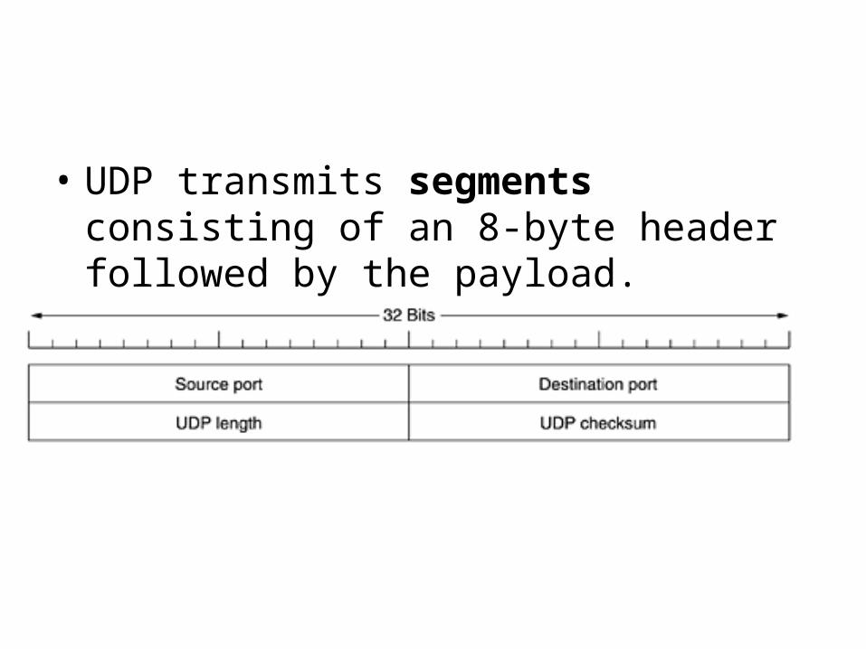
• UDP transmits segments consisting of an 8-byte header followed by the payload.
• The source port is primarily needed when a reply must be sent back to the source.
• By copying the source port field from the incoming segment into the destination port field of the outgoing segment, the process sending the reply can specify which process on the sending machine is to get it.
• The UDP length field includes the 8-byte header and the data. The UDP checksum is optional and stored as 0 if not computed (a true computed 0 is stored as all 1s).
• It is probably worth mentioning explicitly some of the things that UDP does not do.
• It does not do flow control, error control, or retransmission upon receipt of a bad segment. All of that is up to the user processes.
• What it does do is provide an interface to the IP protocol with the added feature of de-multiplexing multiple processes using the ports.
• One area where UDP is especially useful is in client-server situations.
• Often, the client sends a short request to the server and expects a short reply back. If either the request or reply is lost, the client can just time out and try again.
• Not only is the code simple, but fewer messages are• required (one in each direction) than with a protocol
requiring an initial setup.
An application that uses UDP this way is DNS (the Domain Name System)
• A program that needs to look up the IP address of some host name, for example, www.cs.berkeley.edu, can send a UDP packet containing the host name to a DNS server.
• The server replies with a UDP packet containing the host's IP address.
Remote Procedure Call
• Sending a message to a remote host and getting a reply back is a lot like making a function call in a programming language.
• Request-reply interactions on networks to be cast in the form of procedure calls.
• Such an arrangement makes network applications much easier to program and more familiar to deal with.

• Information can be transported from the caller to the callee in the parameters and can come back in the procedure result.
• No message passing is visible to the programmer.
• This technique is known as RPC (Remote Procedure Call) and has become the basis for many networking applications.
• Traditionally, the calling procedure is known as the client and the called procedure is known as the server, and we will use those names here too.
• To call a remote procedure, the client program must be bound with a small library procedure, called the client stub, that represents the server procedure in the client's address space.
• Similarly, the server is bound with a procedure called the server stub.
• Step 1 is the client calling the client stub. This call is a local procedure call, with the parameters pushed onto the stack in the normal way.
• Step 2 is the client stub packing the parameters into a message and making a system call to send the message.
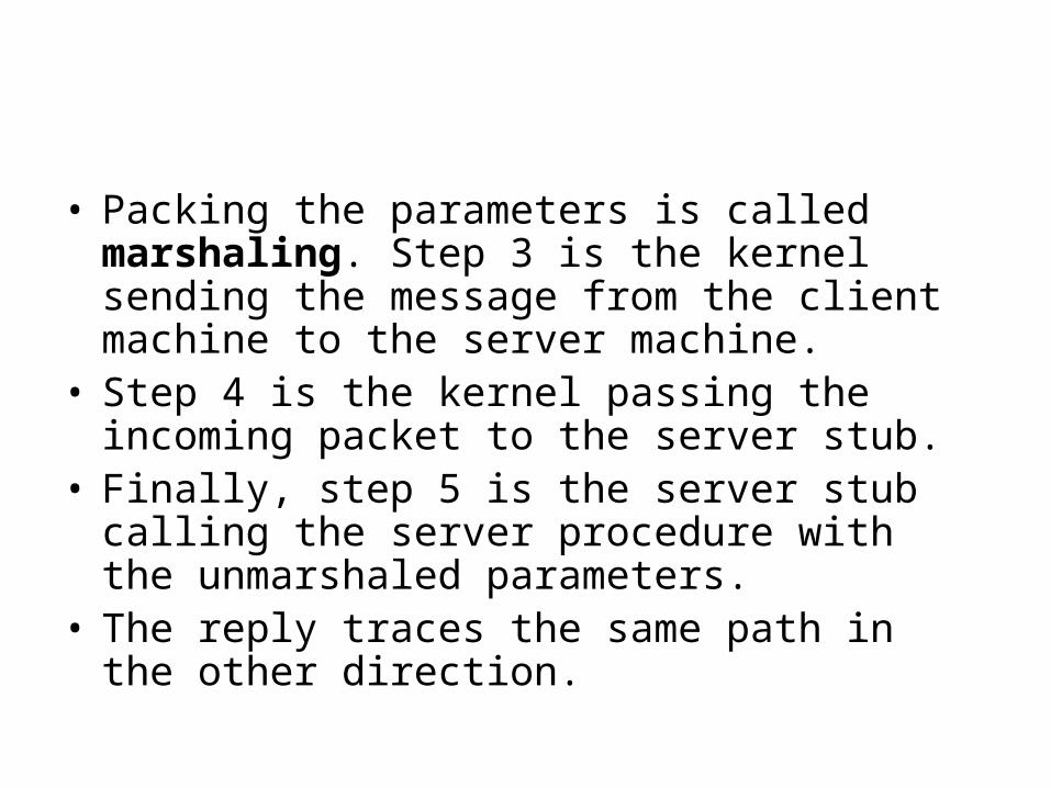
• Packing the parameters is called marshaling. Step 3 is the kernel sending the message from the client machine to the server machine.
• Step 4 is the kernel passing the incoming packet to the server stub.
• Finally, step 5 is the server stub calling the server procedure with the unmarshaled parameters.
• The reply traces the same path in the other direction.
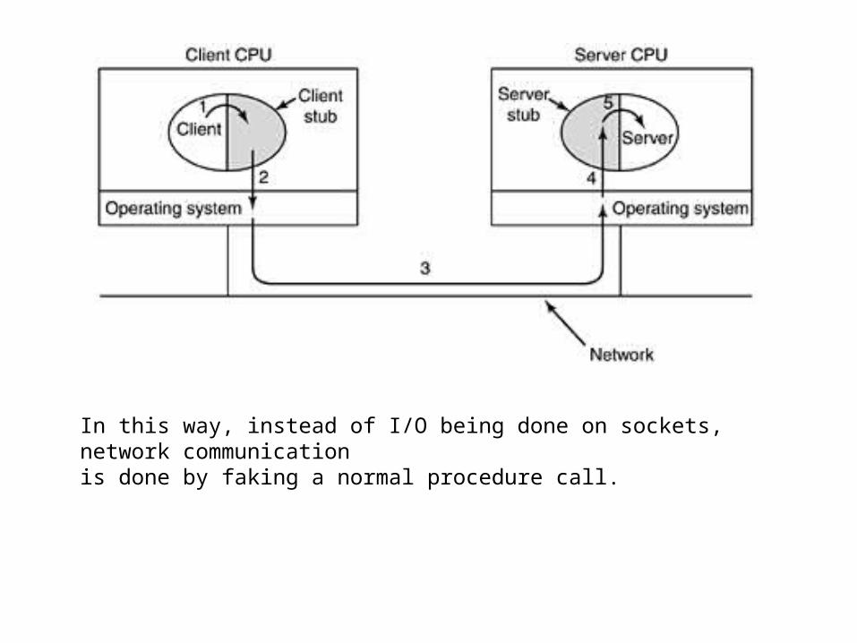
In this way, instead of I/O being done on sockets, network communicationis done by faking a normal procedure call.
The Real-Time Transport Protocol
• Client-server RPC is one area in which UDP is widely used. Another one is real-time multimedia applications.
• In particular, as Internet radio, Internet telephony, music-on-demand, videoconferencing, video-on-demand
• The multimedia application consists of multiple audio, video, text, and possibly other streams.
• These are fed into the RTP library, which is in user space along with the application.
• This library then multiplexes the streams and encodes them in RTP packets, which it then stuffs into a socket.
• At the other end of the socket (in the operating system kernel), UDP packets are generated and embedded in IP packets.
• If the computer is on an Ethernet, the IP packets are then put in Ethernet frames for transmission.
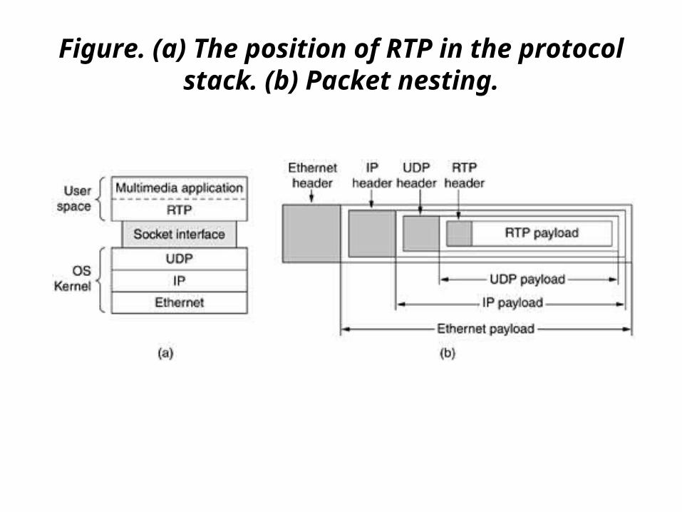
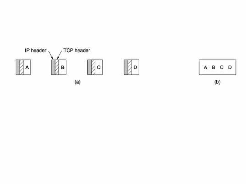
Figure. (a) The position of RTP in the protocol stack. (b) Packet nesting.
• It is a transport protocol that is implemented in the application layer.
• The basic function of RTP is to multiplex several real-time data streams onto a single stream of UDP packets.
• The UDP stream can be sent to a single destination (unicasting) or to multiple destinations (multicasting).
• Because RTP just uses normal UDP, its packets are not treated specially by the routers unless some normal IP quality-of-service features are enabled.
• If a packet is missing, the best action for the destination to take is to approximate the missing value by interpolation.
• Retransmission is not a practical option since the retransmitted packet would probably arrive too late to be useful.
• As a consequence, RTP has no flow control, no error control, no acknowledgements, and no mechanism to request retransmissions.
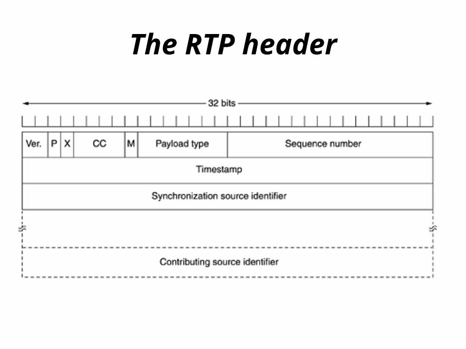
The RTP header
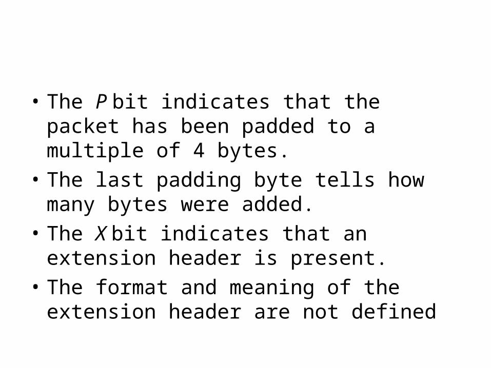
• The P bit indicates that the packet has been padded to a multiple of 4 bytes.
• The last padding byte tells how many bytes were added.
• The X bit indicates that an extension header is present.
• The format and meaning of the extension header are not defined
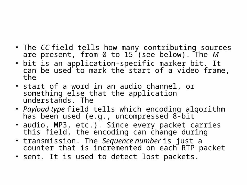
• The CC field tells how many contributing sources are present, from 0 to 15 (see below). The M
• bit is an application-specific marker bit. It can be used to mark the start of a video frame, the
• start of a word in an audio channel, or something else that the application understands. The
• Payload type field tells which encoding algorithm has been used (e.g., uncompressed 8-bit
• audio, MP3, etc.). Since every packet carries this field, the encoding can change during
• transmission. The Sequence number is just a counter that is incremented on each RTP packet
• sent. It is used to detect lost packets.
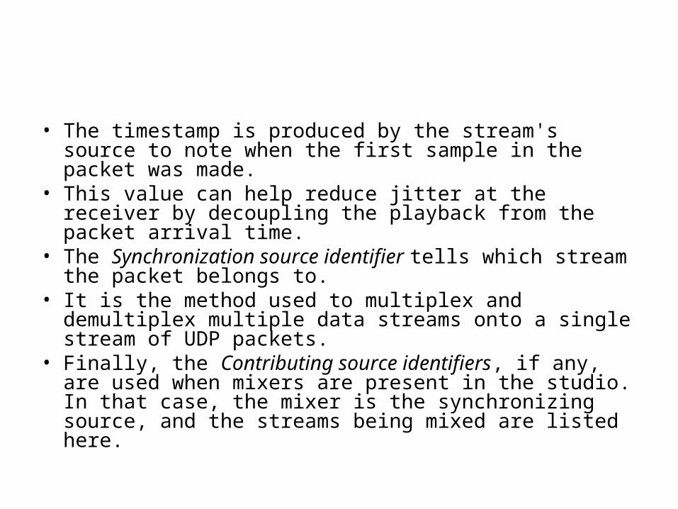
• The timestamp is produced by the stream's source to note when the first sample in the packet was made.
• This value can help reduce jitter at the receiver by decoupling the playback from the packet arrival time.
• The Synchronization source identifier tells which stream the packet belongs to.
• It is the method used to multiplex and demultiplex multiple data streams onto a single stream of UDP packets.
• Finally, the Contributing source identifiers, if any, are used when mixers are present in the studio. In that case, the mixer is the synchronizing source, and the streams being mixed are listed here.
The Internet Transport Protocols: TCP
• TCP (Transmission Control Protocol) was specifically designed to provide a reliable end-to –end byte stream over an unreliable internetwork.
• An internetwork differs from a single network because different parts may have wildly different topologies, bandwidths, delays, packet sizes, and other parameters.
• TCP was designed to dynamically adapt to properties of the internetwork and to be robust in the face of many kinds of failures.
• A TCP entity accepts user data streams from local processes, breaks them up into pieces not exceeding 64 KB (in practice, often 1460 data bytes in order to fit in a single Ethernet frame with the IP and TCP headers), and sends each piece as a separate IP datagram.
• When datagrams containing TCP data arrive at a machine, they are given to the TCP entity, which reconstructs the original byte streams.
• The IP layer gives no guarantee that datagrams will be delivered properly, so it is up to TCP to time out and retransmit them as need be.
The TCP Service Model
• TCP service is obtained by both the sender and receiver creating end points, called sockets
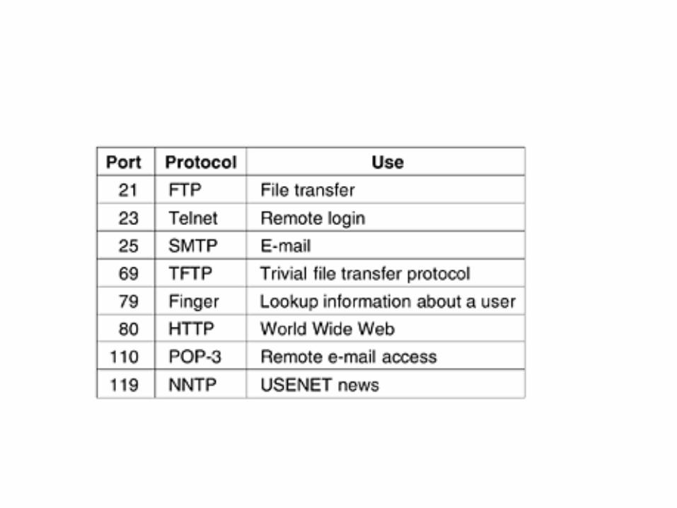
• Each socket has a socket number (address) consisting of the IP address of the host and a 16-bit number local to that host, called a port. A port is the TCP name for a TSAP.
• For TCP service to be obtained, a connection must be explicitly established between a socket on the sending machine and a socket on the receiving machine.
• A socket may be used for multiple connections at the same time. In other words, two or more connections may terminate at the same socket.
• All TCP connections are full duplex and point-to-point. Full duplex means that traffic can go in both directions at the same time.
• Point-to-point means that each connection has exactly two end points.
• TCP does not support multicasting or broadcasting.
• A TCP connection is a byte stream, not a message stream.
• Message boundaries are not preserved end to end. For example, if the sending process does four 512-byte writes to a TCP stream, these data may be delivered to the receiving process as four 512-byte chunks, two 1024-byte chunks, one 2048-byte chunk
• When an application passes data to TCP, TCP may send it immediately or buffer it (in order to collect a larger amount to send at once), at its discretion.
• However, sometimes, the application really wants the data to be sent immediately.
• For example, suppose a user is logged in to a remote machine. After a command line has been finished and the carriage return typed, it is essential that the line be shipped off to the remote machine immediately and not buffered until the next line comes in.
• To force data out, applications can use the PUSH flag, which tells TCP not to delay the transmission.
• One last feature of the TCP service that is worth mentioning here is urgent data.
• When an interactive user hits the DEL or CTRL-C key to break off a remote computation that has already begun, the sending application puts some control information in the data stream and gives it to TCP along with the URGENT flag.
• This event causes TCP to stop accumulating data and transmit everything it has for that connection immediately.
• When the urgent data are received at the destination, the receiving application is interrupted (e.g., given a signal in UNIX terms) so it can stop whatever it was doing and read the data stream to find the urgent data.
• The end of the urgent data is marked so the application knows when it is over.
• The start of the urgent data is not marked. It is up to the application to figure that out.
• This scheme basically provides a crude signaling mechanism and leaves everything else up to the application.
The TCP Protocol
• The sending and receiving TCP entities exchange data in the form of segments.
• A TCP segment consists of a fixed 20-byte header (plus an optional part) followed by zero or more data bytes. The TCP software decides how big segments should be. It can accumulate data from several writes into one segment or can split data from one write over multiple segments.
• Two limits restrict the segment size. First, each segment, including the TCP header, must fit in the 65,515-byte IP payload.
• Second, each network has a maximum transfer unit, or MTU, and each segment must fit in the MTU. In practice, the MTU is generally 1500 bytes (the Ethernet payload size) and thus defines the upper bound on segment size.
• The basic protocol used by TCP entities is the sliding window protocol. When a sender transmits a segment, it also starts a timer.
• When the segment arrives at the destination, the receiving TCP entity sends back a segment (with data if any exist, otherwise without data) bearing an acknowledgement number equal to the next sequence number it expects to receive.
• If the sender's timer goes off before the acknowledgement is received, the sender transmits the segment again.
• Segments can arrive out of order, so bytes 3072–4095 can arrive but cannot be acknowledged because bytes 2048–-3071 have not turned up yet.
• Segments can also be delayed so long in transit that the sender times out and retransmits them.
The TCP Segment Header
• The fixed header may be followed by header options. After the options, if any, up to 65,535 - 20 - 20 = 65,495 data bytes may follow, where the first 20 refer to the IP header and the second to the TCP header.
• Segments without any data are legal and are commonly used for cknowledgements and control messages.
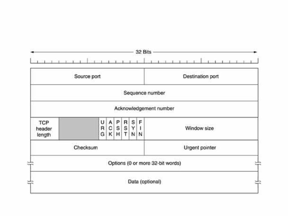
• The Source port and Destination port fields identify the local end points of the connection.
• A port plus its host's IP address forms a 48-bit unique end point. The source and destination end points together identify the connection.
• The TCP header length tells how many 32-bit words are contained in the TCP header.
• This information is needed because the Options field is of variable length, so the header is, too.
• Now come six 1-bit flags. URG is set to 1 if the Urgent pointer is in use. The Urgent pointer is used to indicate a byte offset from the current sequence number at which urgent data are to be found.
• This facility is in lieu of interrupt messages. As we mentioned above, this facility is a bare-bones way of allowing the sender to signal the receiver without getting TCP itself involved in the reason for the interrupt.
• The ACK bit is set to 1 to indicate that the Acknowledgement number is valid. If ACK is 0, the segment does not contain an acknowledgement so the Acknowledgement number field is ignored.
• The PSH bit indicates PUSHed data. The receiver is hereby kindly requested to deliver the data to the application upon arrival and not buffer it until a full buffer has been received (which it might otherwise do for efficiency).
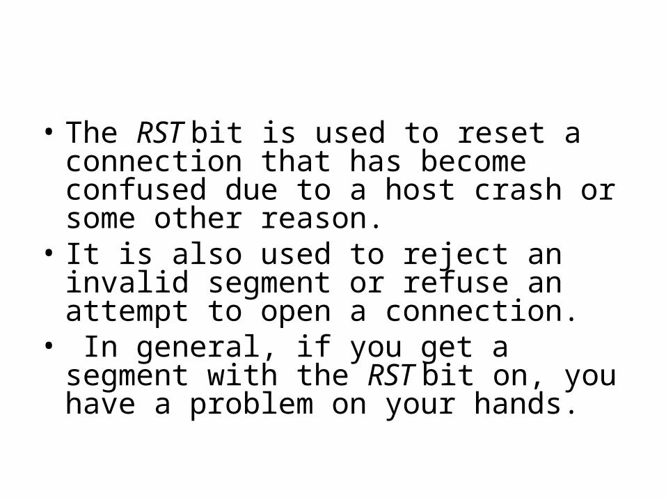
• The RST bit is used to reset a connection that has become confused due to a host crash or some other reason.
• It is also used to reject an invalid segment or refuse an attempt to open a connection.
• In general, if you get a segment with the RST bit on, you have a problem on your hands.
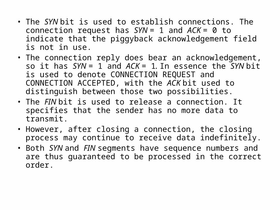
• The SYN bit is used to establish connections. The connection request has SYN = 1 and ACK = 0 to indicate that the piggyback acknowledgement field is not in use.
• The connection reply does bear an acknowledgement, so it has SYN = 1 and ACK = 1. In essence the SYN bit is used to denote CONNECTION REQUEST and CONNECTION ACCEPTED, with the ACK bit used to distinguish between those two possibilities.
• The FIN bit is used to release a connection. It specifies that the sender has no more data to transmit.
• However, after closing a connection, the closing process may continue to receive data indefinitely.
• Both SYN and FIN segments have sequence numbers and are thus guaranteed to be processed in the correct order.
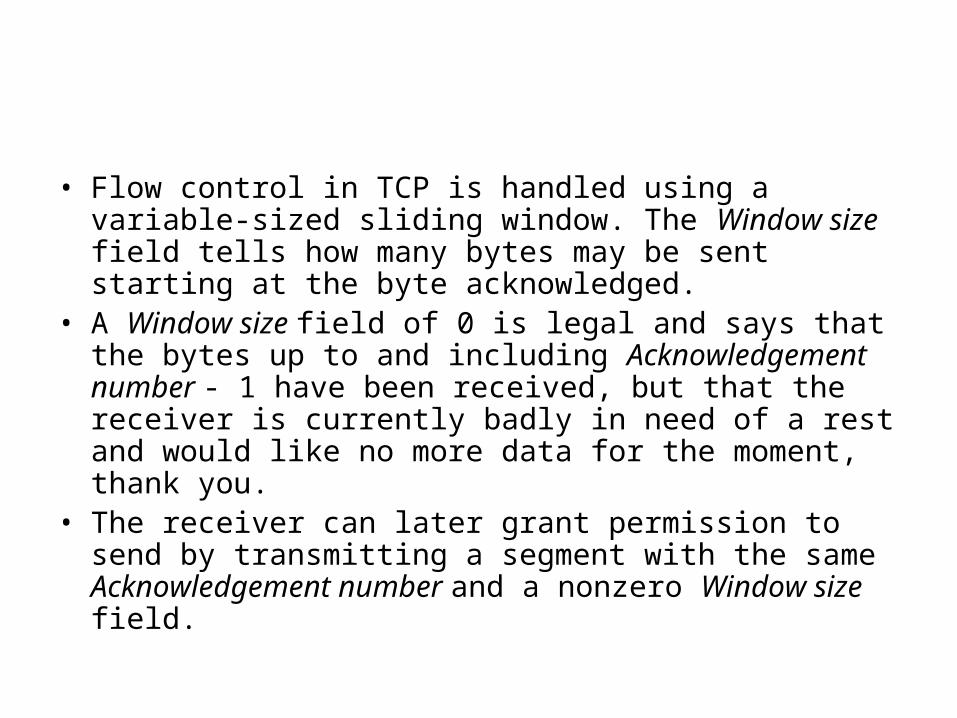
• Flow control in TCP is handled using a variable-sized sliding window. The Window size field tells how many bytes may be sent starting at the byte acknowledged.
• A Window size field of 0 is legal and says that the bytes up to and including Acknowledgement number - 1 have been received, but that the receiver is currently badly in need of a rest and would like no more data for the moment, thank you.
• The receiver can later grant permission to send by transmitting a segment with the same Acknowledgement number and a nonzero Window size field.