Embed Size (px)
Citation preview
UddeholmSverker® 3

Uddeholm Sverker 3
This information is based on our present state of knowledge and is intended to provide general notes on our products and their uses. It should not therefore be construed as a warranty of specific properties of the products described or a warranty for fitness for a particular purpose.
Classified according to EU Directive 1999/45/ECFor further information see our “Material Safety Data Sheets”.
Edition 9, 04.2019
© UDDEHOLMS ABNo part of this publication may be reproduced or transmitted for commercial purposes without permission of the copyright holder.
Uddeholm Sverker 3
3
PROPERTIESPHYSICAL DATA
HRC
Tools for: Bending, raising, deep-drawing; Rim-rolling, spinning and flow-forming 56–62
Tube- and section-forming rolls 58–62
Cold drawing/sizing dies 58–62
Compacting dies for metal powder parts 58–62
Master hobs for cold hobbing 56–60
Dies for moulding of:Ceramics, bricks, tiles; Grinding wheels; Tablets; Abrasive plastics 58–62
Gauges, measuring tools; Guide rails, bushes, sleeves; Knurling tools; Sandblast nozzles 58–62
Crushing hammers 56–60
Swaging blocks 56–60
FORMINGGENERALUddeholm Sverker 3 is a high-carbon, high-chromium tool steel alloyed with tungsten, characterized by:
• Highest wear resistance
• High compressive strength
• High surface hardness after hardening
• Good through-hardening properties
• Good stability in hardening
• Good resistance to tempering-back
Uddeholm Sverker 3 has gained widespread acceptance as a steel with exceptional wear resistance, suitable for long-life tooling with low repair and mainten ance costs, for maxi-mum production economy.
APPLICATIONSBLANKINGUddeholm Sverker 3 is recommended for applications demanding maximum wear-resistance, such as blanking and shearing tools for thin, hard mater ials; long-run press tools; forming tools; moulds for ceramics and abrasive plastics.
Hardened and tempered to 62 HRC. Data at ambient temperature and elevated temperatures.
Temperature 20°C 200°C 400° (68°F) (390°F) (750°F)
Densitykg/m3 7 700 7 650 7 600lbs/in3 0,277 0,276 0,275
Modulus of elasticity
N/mm2 194 000 189 000 173 000kp/mm2 19 800 19 300 17 600tsi 12 565 12 240 12 040psi 28.1 x 10⁶ 27.4 x 10⁶ 25.1 x 10⁶
Coefficient of thermal expansion
per °C from 20° – 11.0 x 10⁻⁶ 10.8 x 10⁻⁶
per °F from 68°F – 6.1 x 10⁻⁶ 6.0 x 10⁻⁶
Thermal conductivity
W/m °C 20,5 21,5 23,0Btu in/ft2 h °F 142 149 159
Specific heatJ/kg °C 460 – –Btu/lb °F 0.110 – –
COMPRESSIVE STRENGTH
The figures are to be considered as approximate. Compressive strength Rc0.2 Hardness MPa
62 HRC 2200 60 HRC 2100 55 HRC 1850 50 HRC 1600
Typicalanalysis %
Standardspecification AISI D6, (AISI D3), (W.-Nr. 1.2436)
Deliverycondition Soft annealed to approx. 240 HB
Colour code Red
C Si Mn CrW 2.05 0.3 0.8 12.7 1.1
Material hardness Material ≤ 180 > 180 thickness HRC HRC
Tools for:Blanking, punching, cropping, shearing, trimming, clipping < 3 60–62 56–58 Short, cold shears for thin materials, shredding knives for plastics waste 56–60
Circular shears for light gauge sheet, car-board etc. 58–60
Clipping, trimming tools for forgings 58–60
Wood milling cutters, reamers, broaches 56–58
Uddeholm Sverker 3
4
QUENCHING MEDIA• Oil
• Vacuum (high speed gas)
• Forced air/gas
• Martempering bath or fluidized bed at 180–500°C (360–930°F), then cooling in air
Note: Temper the tool as soon as its temperature reaches 50–70°C (120–160°F).
HEAT TREATMENTSOFT ANNEALINGProtect the steel and heat through to 850°C (1560°F). Then cool in the furnace at 10°C (20°F) per hour to 650°C (1200°F), then freely in air.
STRESS RELIEVINGAfter rough machining the tool should be heated through to 650°C (1200°F), holding time 2 hours. Cool slowly to 500°C (930°F), then freely in air.
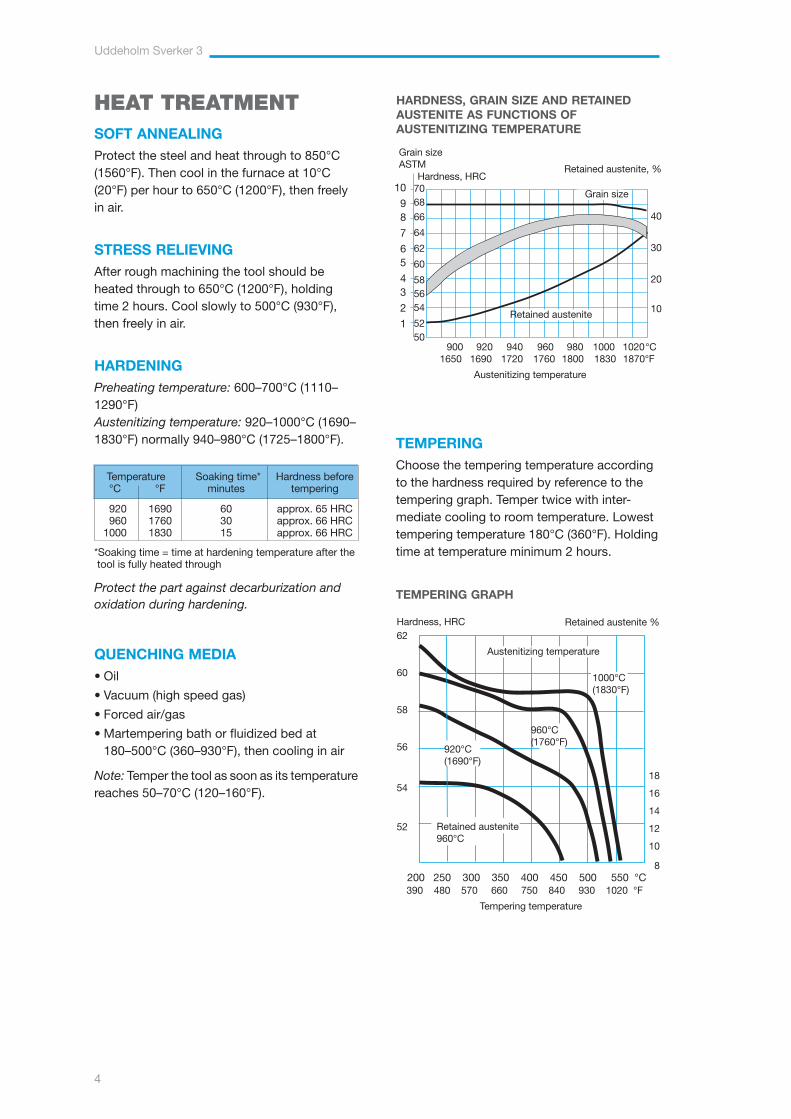
HARDENINGPreheating temperature: 600–700°C (1110–1290°F)Austenitizing temperature: 920–1000°C (1690–1830°F) normally 940–980°C (1725–1800°F).
390 480 570 660 750 840 930 1020 °F
Tempering temperature
Austenitizing temperature
Hardness, HRC62
60
58
56
54
52
1000°C(1830°F)
960°C(1760°F)
18
16
14
12
10
8200 250 300 350 400 450 500 550 °C
Retained austenite, %
40
30
20
10
Hardness, HRC7068
66
64
62
60
585654
5250
Grain sizeASTM
Retained austenite
Grain size
HARDNESS, GRAIN SIZE AND RETAINED AUSTENITE AS FUNCTIONS OF AUSTENITIZING TEMPERATURE
10
98
7
65
43
2
1
Retained austenite %
TEMPERING GRAPH
TEMPERINGChoose the tempering temperature according to the hardness required by reference to the tempering graph. Temper twice with inter-mediate cooling to room temperature. Lowest tempering temperature 180°C (360°F). Holding time at temperature minimum 2 hours.
Retained austenite 960°C
900 920 940 960 980 1000 1020 °C 1650 1690 1720 1760 1800 1830 1870°F
Austenitizing temperature
920°C(1690°F)
Temperature Soaking time* Hardness before °C °F minutes tempering
920 1690 60 approx. 65 HRC 960 1760 30 approx. 66 HRC 1000 1830 15 approx. 66 HRC
* Soaking time = time at hardening temperature after the tool is fully heated through
Protect the part against decarburization and oxidation during hardening.
Uddeholm Sverker 3
5
DIMENSIONAL CHANGESDURING HARDENING
Sample plate, 100 x 100 x 25 mm, 4" x 4" x 1"
DIMENSIONAL CHANGES DURING TEMPERING
+0,20
+0,16
+0,12
+0,08
+0,06
0
–0,04
–0,08
–0,12
–0,16
–0,20
Dimensional change %
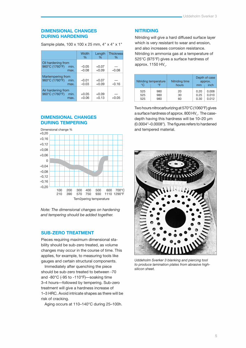
Uddeholm Sverker 3 blanking and piercing tool to produce lamination plates from abrasive high-silicon sheet.
Note: The dimensional changes on hardening and tempering should be added together.
Two hours nitrocarburizing at 570°C (1060°F) gives a surface hardness of approx. 800 HV1. The case- depth having this hardness will be 10–20 µm (0.0004"–0.0008"). The figures refers to hardened and tempered material.
NITRIDINGNitriding will give a hard diffused surface layer which is very resistant to wear and erosion, and also increases corrosion resistance. Nitriding in ammonia gas at a temperature of 525°C (975°F) gives a surface hardness of approx. 1150 HV1.
SUB-ZERO TREATMENTPieces requiring maximum dimensional sta-bility should be sub-zero treated, as volume changes may occur in the course of time. This applies, for example, to measuring tools like gauges and certain structural components.
Immediately after quenching the piece should be sub-zero treated to between -70 and -80°C (-95 to -110°F)—soaking time 3–4 hours—followed by tempering. Sub-zero treatment will give a hardness increase of 1–3 HRC. Avoid intricate shapes as there will be risk of cracking.
Aging occurs at 110–140°C during 25–100h.
Width Length Thickness % % %
Oil hardening from 960°C (1760°F) min. –0.05 +0.07 — max. –0.08 +0.09 –0.08
Martempering from 960°C (1760°F) min. –0.01 +0.07 — max. –0.03 +0.09 –0.16
Air hardening from 960°C (1760°F) min. +0.05 +0.09 — max. +0.06 +0.13 +0.05
100 200 300 400 500 600 700°C 210 390 570 750 930 1110 1290°F
Tem2pering temperature
Depth of case Nitriding temperature Nitriding time approx. °C °F hours mm inch
525 980 20 0.20 0.008 525 980 30 0.25 0.010 525 980 60 0.30 0.012
Uddeholm Sverker 3
6
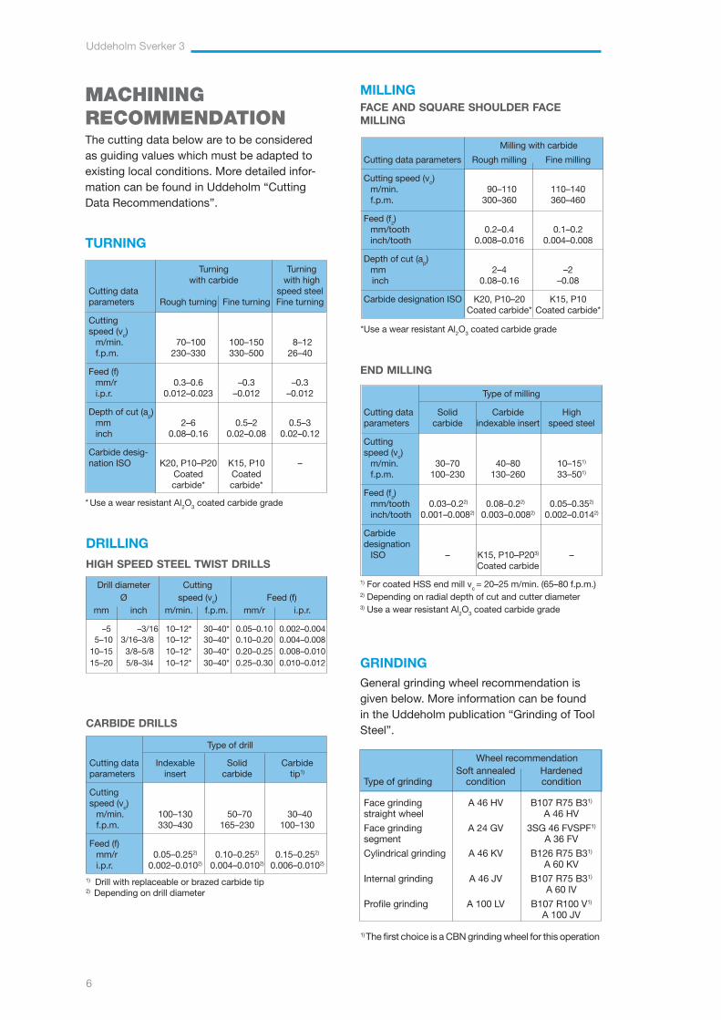
END MILLING
Type of milling
Cutting data Solid Carbide Highparameters carbide indexable insert speed steel
Cutting speed (vc)
m/min. 30–70 40–80 10–151)
f.p.m. 100–230 130–260 33–501)
Feed (fz)mm/tooth 0.03–0.22) 0.08–0.22) 0.05–0.352)
inch/tooth 0.001–0.0082) 0.003–0.0082) 0.002–0.0142)
Carbide designation
ISO – K15, P10–P203) – Coated carbide
1) For coated HSS end mill vc = 20–25 m/min. (65–80 f.p.m.)2) Depending on radial depth of cut and cutter diameter3) Use a wear resistant Al2O3 coated carbide grade
MILLINGFACE AND SQUARE SHOULDER FACE MILLING
Milling with carbide
Cutting data parameters Rough milling Fine milling
Cutting speed (vc) m/min. 90–110 110–140f.p.m. 300–360 360–460
Feed (fz) mm/tooth 0.2–0.4 0.1–0.2inch/tooth 0.008–0.016 0.004–0.008
Depth of cut (ap)mm 2–4 –2 inch 0.08–0.16 –0.08
Carbide designation ISO K20, P10–20 K15, P10 Coated carbide* Coated carbide*
*Use a wear resistant Al2O3 coated carbide grade
MACHINING RECOMMENDATIONThe cutting data below are to be considered as guiding values which must be adapted to existing local conditions. More detailed infor-mation can be found in Uddeholm “Cutting Data Recommendations”.
TURNING
Turning Turning with carbide with highCutting data speed steelparameters Rough turning Fine turning Fine turning
Cutting speed (vc)
m/min. 70–100 100–150 8–12f.p.m. 230 –330 330–500 26–40
Feed (f)mm/r 0.3–0.6 –0.3 –0.3i.p.r. 0.012–0.023 –0.012 –0.012
Depth of cut (ap) mm 2–6 0.5–2 0.5–3inch 0.08–0.16 0.02–0.08 0.02–0.12
Carbide desig-nation ISO K20, P10–P20 K15, P10 – Coated Coated carbide* carbide*
* Use a wear resistant Al2O3 coated carbide grade
DRILLING
HIGH SPEED STEEL TWIST DRILLS
Drill diameter Cutting Ø speed (vc) Feed (f)
mm inch m/min. f.p.m. mm/r i.p.r.
–5 –3/16 10–12* 30–40* 0.05–0.10 0.002–0.004 5–10 3/16–3/8 10–12* 30–40* 0.10–0.20 0.004–0.008 10–15 3/8–5/8 10–12* 30–40* 0.20–0.25 0.008–0.010 15–20 5/8–3|4 10–12* 30–40* 0.25–0.30 0.010–0.012
CARBIDE DRILLS
Type of drill
Cutting data Indexable Solid Carbideparameters insert carbide tip1)
Cutting speed (vc)
m/min. 100–130 50–70 30–40f.p.m. 330–430 165–230 100–130
Feed (f)mm/r 0.05–0.252) 0.10–0.252) 0.15–0.252)
i.p.r. 0.002–0.0102) 0.004–0.0102) 0.006–0.0102)
1) Drill with replaceable or brazed carbide tip2) Depending on drill diameter
Wheel recommendation Soft annealed HardenedType of grinding condition condition
Face grinding A 46 HV B107 R75 B31)
straight wheel A 46 HV
Face grinding A 24 GV 3SG 46 FVSPF1)
segment A 36 FV
Cylindrical grinding A 46 KV B126 R75 B31)
A 60 KV
Internal grinding A 46 JV B107 R75 B31)
A 60 IV
Profile grinding A 100 LV B107 R100 V1)
A 100 JV
1) The first choice is a CBN grinding wheel for this operation
GRINDINGGeneral grinding wheel recommendation is given below. More information can be found in the Uddeholm publication “Grinding of Tool Steel”.
Uddeholm Sverker 3
7
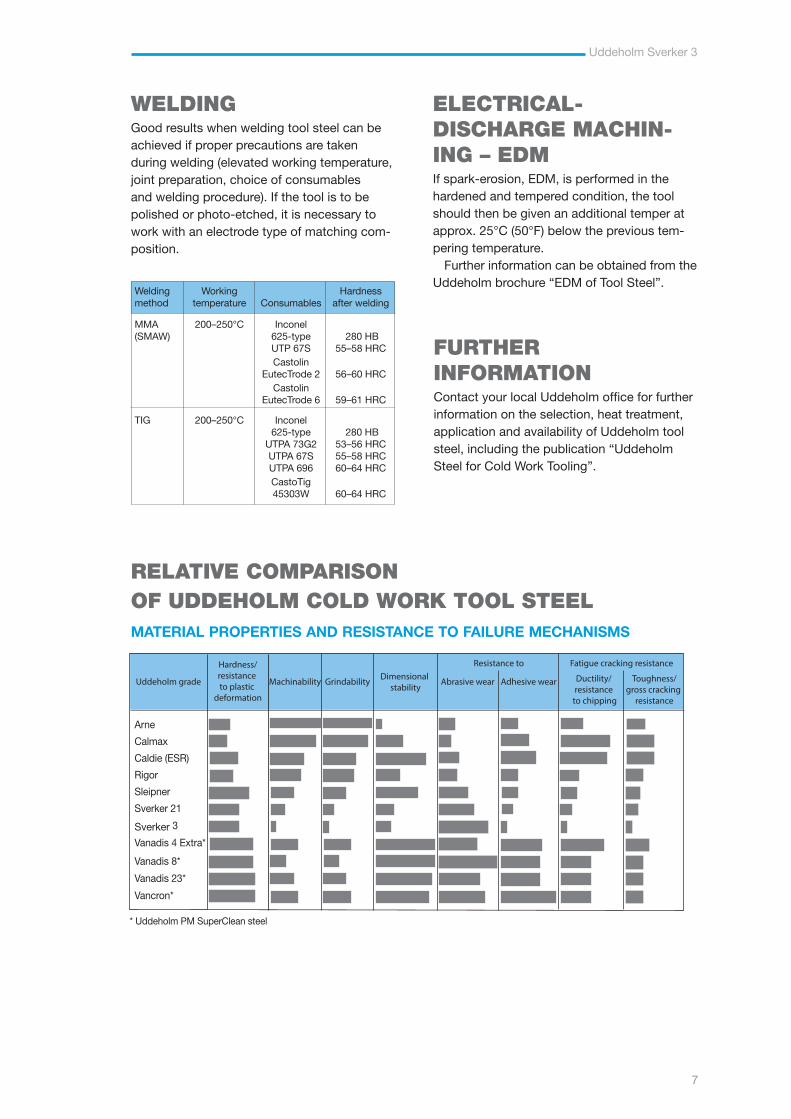
* Uddeholm PM SuperClean steel
Arne
Calmax
Caldie (ESR)
Rigor
Sleipner
Sverker 21
Sverker 3
Vanadis 4 Extra*
Vanadis 8*
Vanadis 23*
Vancron*
Hardness/resistance to plastic
deformation
Machinability Grindability Dimensional stability
Abrasive wear Adhesive wear Ductility/ resistance
to chipping
Toughness/gross cracking
resistance
Resistance to Fatigue cracking resistance
Uddeholm grade
RELATIVE COMPARISONOF UDDEHOLM COLD WORK TOOL STEELMATERIAL PROPERTIES AND RESISTANCE TO FAILURE MECHANISMS
FURTHER INFORMATIONContact your local Uddeholm office for further information on the selection, heat treatment, application and availability of Uddeholm tool steel, including the publication “Uddeholm Steel for Cold Work Tooling”.
ELECTRICAL- DISCHARGE MACHIN-ING – EDMIf spark-erosion, EDM, is performed in the hardened and tempered condition, the tool should then be given an additional temper at approx. 25°C (50°F) below the previous tem-pering temperature.
Further information can be obtained from the Uddeholm brochure “EDM of Tool Steel”.
WELDINGGood results when welding tool steel can be achieved if proper precautions are taken during welding (elevated working temperature, joint preparation, choice of consumables and welding procedure). If the tool is to be polished or photo-etched, it is necessary to work with an electrode type of matching com-position.
Welding Working Hardnessmethod temperature Consumables after welding
MMA 200–250°C Inconel(SMAW) 625-type 280 HB UTP 67S 55–58 HRC Castolin EutecTrode 2 56–60 HRC Castolin EutecTrode 6 59–61 HRC
TIG 200–250°C Inconel 625-type 280 HB UTPA 73G2 53–56 HRC UTPA 67S 55–58 HRC UTPA 696 60–64 HRC CastoTig 45303W 60–64 HRC
Uddeholm Sverker 3
8
THE CONVENTIONAL TOOL STEEL PROCESSThe starting material for our tool steel is carefully selected from high quality recyclable steel. Together with ferroalloys and slag formers, the recyclable steel is melted in an electric arc furnace. The molten steel is then tapped into a ladle.
The de-slagging unit removes oxygen-rich slag and after the de-oxidation, alloying and heating of the steel bath are carried out in the ladle furnace. Vacuum degassing removes elements such as hydrogen, nitrogen and sulphur.
In uphill casting the prepared moulds are filled with a controlled flow of molten steel from the ladle. From this, the steel goes directly to our rolling mill or to the forging press to be formed into round or flat bars.
HEAT TREATMENT
Prior to delivery all of the different bar materials are subjected to a heat treatment operation, either as soft annealing or hardening and tempering. These operations provide the steel with the right balance between hardness and toughness.
MACHINING
Before the material is finished and put into stock, we also rough machine the bar profiles to required size and exact tolerances. In the lathe machining of large dimensions, the steel bar rotates against a stationary cutting tool. In peeling of smaller dimensions, the cutting tools revolve around the bar.
To safeguard our quality and guarantee the integrity of the tool steel we perform both surface- and ultrasonic inspections on all bars. We then remove the bar ends and any defects found during the inspection.
Uddeholm Sverker 3
9
ROLLING MILL
FORGING
ELECTRIC ARCFURNACE
STOCK
MACHINING
HEAT
TREATMENT
UPHILL CASTING

Uddeholm Sverker 3
10
Uddeholm Sverker 3
11
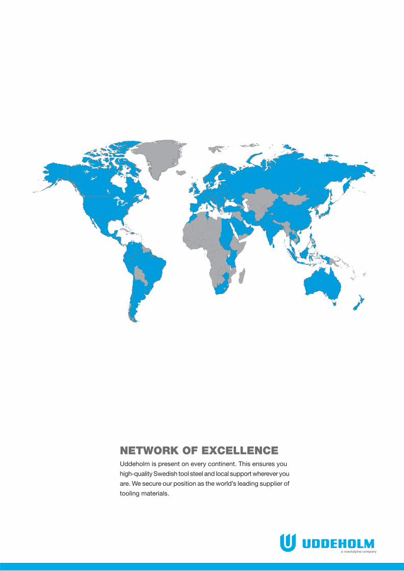
NETWORK OF EXCELLENCEUddeholm is present on every continent. This ensures you
high-quality Swedish tool steel and local support wherever you
are. We secure our position as the world’s leading supplier of
tooling materials.

Uddeholm Sverker 3
12
UD
DEH
OLM
06.2018
Uddeholm is the world’s leading supplier of tooling materials.
This is a position we have reached by improving our customers’
everyday business. Long tradition combined with research and
product development equips Uddeholm to solve any tooling
problem that may arise. It is a challenging process, but the goal is
clear – to be your number one partner and tool steel provider.
Our presence on every continent guarantees you the same high
quality wherever you are. We secure our position as the world’s
leading supplier of tooling materials. We act worldwide. For us
it is all a matter of trust – in long-term partnerships as well as in
developing new products.
For more information, please visit www.uddeholm.com