Embed Size (px)
Citation preview
UDDEHOLM DIEVAR®
SS-EN ISO 9001SS-EN ISO 14001
This information is based on our present state of knowledge and is intended to provide generalnotes on our products and their uses. It should not therefore be construed as a warranty ofspecific properties of the products described or a warranty for fitness for a particular purpose.
Classified according to EU Directive 1999/45/ECFor further information see our “Material Safety Data Sheets”.
UDDEHOLM DIEVAR
Uddeholm Dievar is a specially developed steel grade by Uddeholm,
which provides the best possible performance.
The chemical composition and the very latest in production technique make
the property profile outstanding. The combination of excellent toughness
and very good hot strength gives Uddeholm Dievar a very good heat
checking- and gross cracking resistance.
The steel is suitable in high demand hot work applications like die casting,
forging and extrusion. The property profile makes it also suitable in other
applications, e.g. plastics and High Performance Steel.
Uddeholm Dievar offers the potential for significant improvements in die
life, thereby improving the tooling economy.
Edition 9, 03.2012The latest revised edition of this brochure is the English version,which is always published on our web site www.uddeholm.com
3
UDDEHOLM DIEVAR
Typical C Si Mn Cr Mo Vanalysis % 0.35 0.2 0.5 5.0 2.3 0.6
Standardspecification None
Deliverycondition Soft annealed to approx. 160 HB
Colour code Yellow/grey
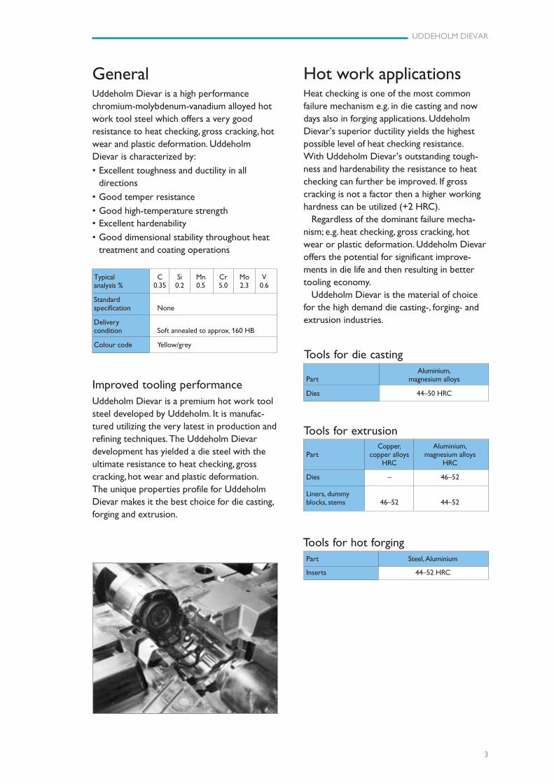
GeneralUddeholm Dievar is a high performancechromium-molybdenum-vanadium alloyed hotwork tool steel which offers a very goodresistance to heat checking, gross cracking, hotwear and plastic deformation. UddeholmDievar is characterized by:
• Excellent toughness and ductility in alldirections
• Good temper resistance
• Good high-temperature strength• Excellent hardenability
• Good dimensional stability throughout heattreatment and coating operations
Improved tooling performanceUddeholm Dievar is a premium hot work toolsteel developed by Uddeholm. It is manufac-tured utilizing the very latest in production andrefining techniques. The Uddeholm Dievardevelopment has yielded a die steel with theultimate resistance to heat checking, grosscracking, hot wear and plastic deformation.The unique properties profile for UddeholmDievar makes it the best choice for die casting,forging and extrusion.
Tools for hot forging
Tools for extrusion
Tools for die casting
Hot work applicationsHeat checking is one of the most commonfailure mechanism e.g. in die casting and nowdays also in forging applications. UddeholmDievar’s superior ductility yields the highestpossible level of heat checking resistance.With Uddeholm Dievar’s outstanding tough-ness and hardenability the resistance to heatchecking can further be improved. If grosscracking is not a factor then a higher workinghardness can be utilized (+2 HRC).
Regardless of the dominant failure mecha-nism; e.g. heat checking, gross cracking, hotwear or plastic deformation. Uddeholm Dievaroffers the potential for significant improve-ments in die life and then resulting in bettertooling economy.
Uddeholm Dievar is the material of choicefor the high demand die casting-, forging- andextrusion industries.
Aluminium,Part magnesium alloys
Dies 44–50 HRC
Copper, Aluminium,Part copper alloys magnesium alloys
HRC HRC
Dies – 46–52
Liners, dummyblocks, stems 46–52 44–52
Part Steel, Aluminium
Inserts 44–52 HRC
4
UDDEHOLM DIEVAR
100 200 300 400 500 600 700°C
210 390 570 750 930 1110 1290 °F
Testing temperature
Rm
A5
Rp0,2
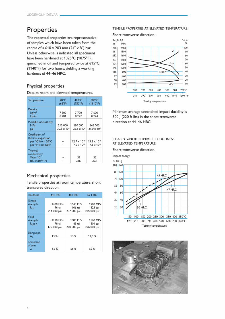
TENSILE PROPERTIES AT ELEVATED TEMPERATURE
Short transverse direction.
CHARPY V-NOTCH IMPACT TOUGHNESSAT ELEVATED TEMPERATURE
Short transverse direction.
50 100 150 200 250 300 350 400 450°C
120 210 300 390 480 570 660 750 840°F
Testing temperature
140
120
100
80
60
40
20
ft. lbs
102
88
73
58
44
30
15
Rm, Rp0,2ksi MPa
290 2000261 1800
232 1600
203 1400
174 1200
145 1000
116 800
87 600
58 400
29 200
%
100
90
80
70
60
50
40
30
20
10
45 HRC
47 HRC
50 HRC
Minimum average unnotched impact ductility is300 J (220 ft lbs) in the short transversedirection at 44–46 HRC.
A5, Z
Impact energy
J
Z
PropertiesThe reported properties are representativeof samples which have been taken from thecentre of a 610 x 203 mm (24" x 8") bar.Unless otherwise is indicated all specimenshave been hardened at 1025°C (1875°F),quenched in oil and tempered twice at 615°C(1140°F) for two hours; yielding a workinghardness of 44–46 HRC.
Physical propertiesData at room and elevated temperatures.
Temperature 20°C 400°C 600°C(68°F) (750°F) (1110°F)
Density,kg/m3 7 800 7 700 7 600lbs/in3 0.281 0.277 0.274
Modulus of elasticityMPa 210 000 180 000 145 000psi 30.5 x 10⁶ 26.1 x 10⁶ 21.0 x 10⁶
Coefficient ofthermal expansion
per °C from 20°C – 12.7 x 10⁻⁶ 13.3 x 10⁻⁶
per °F from 68°F – 7.0 x 10⁻⁶ 7.3 x 10⁻⁶
Thermalconductivity
W/m °C – 31 32Btu in/(ft2h°F) – 216 223
Mechanical propertiesTensile properties at room temperature, shorttransverse direction.
Hardness 44 HRC 48 HRC 52 HRC
Tensilestrength 1480 MPa 1640 MPa 1900 MPa
Rm 96 tsi 106 tsi 123 tsi214 000 psi 237 000 psi 275 000 psi
Yieldstrength 1210 MPa 1380 MPa 1560 MPa
Rp0,2 78 tsi 89 tsi 101 tsi175 000 psi 200 000 psi 226 000 psi
ElongationA5 13 % 13 % 12,5 %
Reductionof area
Z 55 % 55 % 52 %
5
UDDEHOLM DIEVAR
Heat treatment—general recommendationsSoft annealingProtect the steel and heat through to 850°C(1560°F). Then cool in furnace at 10°C (20°F)per hour to 600°C (1110°F), then freely in air.
TEMPER RESISTANCE
The specimens have been hardened andtempered to 45 HRC and then held at differ-ent temperatures from 1 to 100 hours.
0,1 1 10 100
Time, h
500°C(930°F)
Hardness, HRC
50
45
40
35
30
25
600°C(1110°F)
550°C(1020°F)
650°C (1200°F)
Cooling Hard-curve ness T800–500
No. HV 10 (sec)
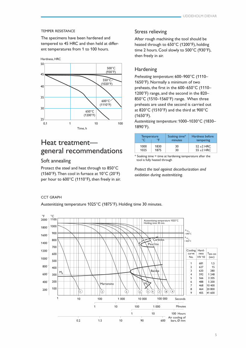
1 681 1,52 627 153 620 2804 592 1 2485 566 3 2056 488 5 2007 468 10 4008 464 20 8009 405 41 600
CCT GRAPH
Austenitizing temperature 1025°C (1875°F). Holding time 30 minutes.
Stress relievingAfter rough machining the tool should beheated through to 650°C (1200°F), holdingtime 2 hours. Cool slowly to 500°C (930°F),then freely in air.
HardeningPreheating temperature: 600–900°C (1110–1650°F). Normally a minimum of twopreheats, the first in the 600–650°C (1110–1200°F) range, and the second in the 820–850°C (1510–1560°F) range. When threepreheats are used the second is carried outat 820°C (1510°F) and the third at 900°C(1650°F).Austenitizing temperature: 1000–1030°C (1830–1890°F).
Temperature Soaking time* Hardness before°C °F minutes tempering
1000 1830 30 52 ±2 HRC1025 1875 30 55 ±2 HRC
* Soaking time = time at hardening temperature after the tool is fully heated through
Protect the tool against decarburization andoxidation during austenitizing.
1
Air cooling ofbars, Ø mm
10 100 1 000 10 000 100 000 Seconds
1 10 100 1 000 Minutes
1 10 100 Hours
0.2 1.5 10 90 600
2000
1800
1600
1400
1200
1000
800
600
400
200
1100
1000
900
800
700
600
500
400
300
200
100
°C°F
A1c f
A1c s
1 2 3 4 5 6 7 8
Martensite
9
Bainite
Carbides
= 890°C
= 820°C
Austenitizing temperature 1025°CHolding time 30 min.
Pearlite
Ms
fM
6
UDDEHOLM DIEVAR
990 1000 1010 1020 1030 1040 1050 °C
1815 1830 1850 1870 1885 1905 1920 °F
Austenitizing temperature
Hardness HRC60
50
40
30
20
10
Retained austenite, %
6
4
2
200 300 400 500 600 700°C
390 570 750 930 1110 1290°F
Tempering temperature (2h + 2h)
EFFECT OF TEMPERING TEMPERATUREON ROOM TEMPERATURE CHARPY V NOTCHIMPACT ENERGY
Short transverse direction.
TEMPERING GRAPH
Hardness, HRC
60
55
50
45
40
35
30
25
Austenitizing temperature
TemperingChoose the tempering temperature accordingto the hardness required by reference to thetempering graph below. Temper minimumthree times for die casting dies and minimumtwice for forging and extrusion tools withintermediate cooling to room temperature.Holding time at temperature minimum 2 hours.
Tempering in the range of 500–550°C (930–1020°F) for the intended f inal hardness will resultin a lower toughness.
ft.lb.
44
37
29
22
15
7
1000°C (1830°F)
Impact strength - KV Joule 60
50
40
30
20
10
QuenchingAs a general rule, quench rates should be asrapid as possible. Accelerated quench rates arerequired to optimize tool properties specifi-cally with regards to toughness and resistanceto gross cracking. However, risk of excessivedistortion and cracking must be considered.
QUENCHING MEDIA
The quenching media should be capable ofcreating a fully hardened microstructure.Different quench rates for Uddeholm Dievarare defined by the CCT graph, page 5.
RECOMMENDED QUENCHING MEDIA
• High speed gas/circulating atmosphere
• Vacuum (high speed gas with sufficientpositive pressure). An interrupted quench at320–450°C (610–840°F) is recommendedwhere distortion control and quench crack-ing are a concern
• Martempering bath, salt bath or fluidized bedat 450–550°C (840–1020°F)
• Martempering bath, salt bath or fluidized bedat 180–200°C (360–390°F)
• Warm oil, approx. 80°C (180°F)
Note: Temper the tool as soon as its tempera-ture reaches 50–70°C (120–160°F).
HARDNESS, GRAIN SIZE ANDRETAINED AUSTENITE AS FUNCTIONS OFAUSTENITIZING TEMPERATURE
10
8
6
60
58
56
54
52
50
Hardness, HRC
GrainsizeASTM
Hardness
Grain size
Retained austenite
Retained austenite %
4
2
0
Temperembrittlement
Retained austenite
1025°C (1875°F)
Temper embrittlement
100 200 300 400 500 600 700°C
210 390 570 750 930 1110 1290°F
Tempering temperature (2 + 2h)
7
UDDEHOLM DIEVAR
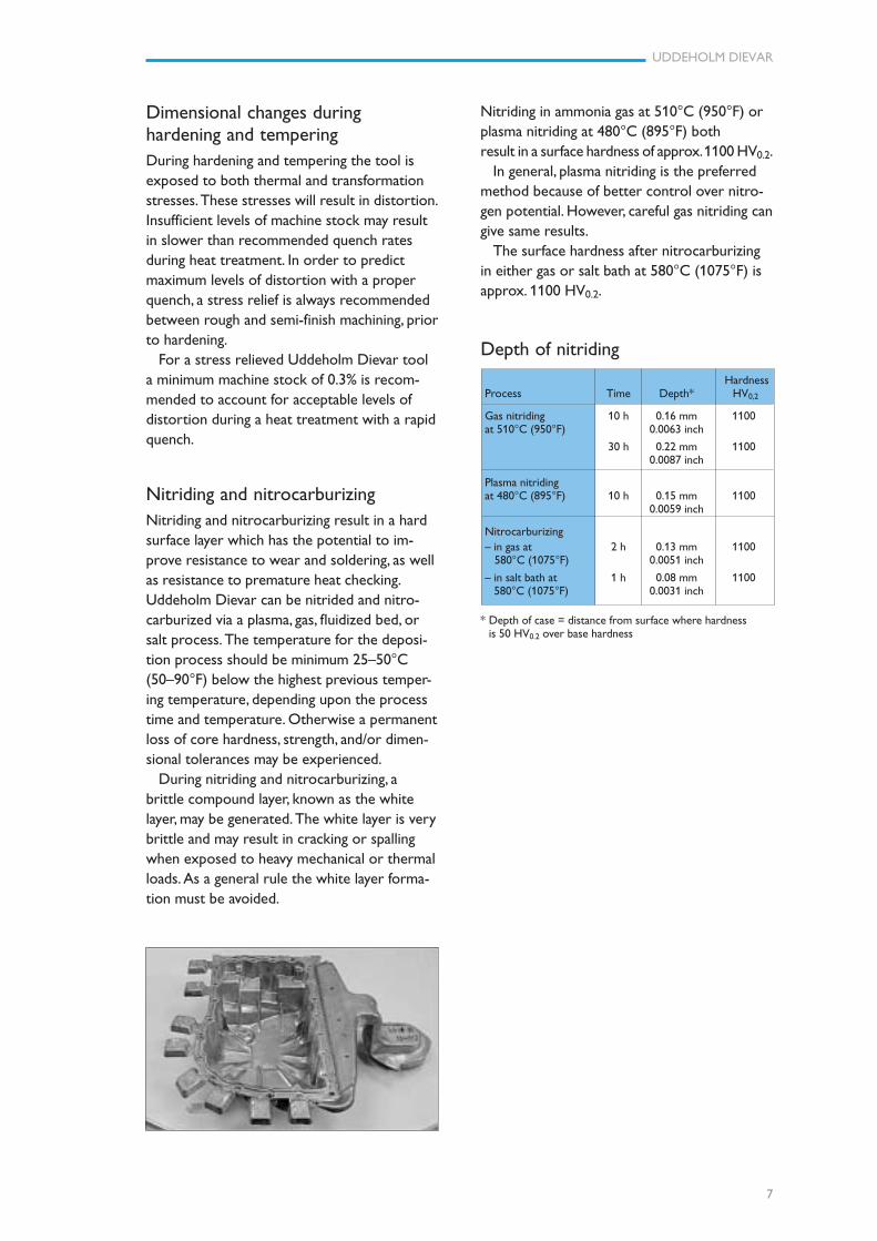
* Depth of case = distance from surface where hardnessis 50 HV0.2 over base hardness
Dimensional changes duringhardening and temperingDuring hardening and tempering the tool isexposed to both thermal and transformationstresses. These stresses will result in distortion.Insufficient levels of machine stock may resultin slower than recommended quench ratesduring heat treatment. In order to predictmaximum levels of distortion with a properquench, a stress relief is always recommendedbetween rough and semi-finish machining, priorto hardening.
For a stress relieved Uddeholm Dievar toola minimum machine stock of 0.3% is recom-mended to account for acceptable levels ofdistortion during a heat treatment with a rapidquench.
Nitriding and nitrocarburizingNitriding and nitrocarburizing result in a hardsurface layer which has the potential to im-prove resistance to wear and soldering, as wellas resistance to premature heat checking.Uddeholm Dievar can be nitrided and nitro-carburized via a plasma, gas, fluidized bed, orsalt process. The temperature for the deposi-tion process should be minimum 25–50°C(50–90°F) below the highest previous temper-ing temperature, depending upon the processtime and temperature. Otherwise a permanentloss of core hardness, strength, and/or dimen-sional tolerances may be experienced.
During nitriding and nitrocarburizing, abrittle compound layer, known as the whitelayer, may be generated. The white layer is verybrittle and may result in cracking or spallingwhen exposed to heavy mechanical or thermalloads. As a general rule the white layer forma-tion must be avoided.
Nitriding in ammonia gas at 510°C (950°F) orplasma nitriding at 480°C (895°F) bothresult in a surface hardness of approx. 1100 HV0.2.
In general, plasma nitriding is the preferredmethod because of better control over nitro-gen potential. However, careful gas nitriding cangive same results.
The surface hardness after nitrocarburizingin either gas or salt bath at 580°C (1075°F) isapprox. 1100 HV0.2.
Depth of nitriding
HardnessProcess Time Depth* HV0,2
Gas nitriding 10 h 0.16 mm 1100at 510°C (950°F) 0.0063 inch
30 h 0.22 mm 11000.0087 inch
Plasma nitridingat 480°C (895°F) 10 h 0.15 mm 1100
0.0059 inch
Nitrocarburizing– in gas at 2 h 0.13 mm 1100 580°C (1075°F) 0.0051 inch
– in salt bath at 1 h 0.08 mm 1100 580°C (1075°F) 0.0031 inch
8
UDDEHOLM DIEVAR
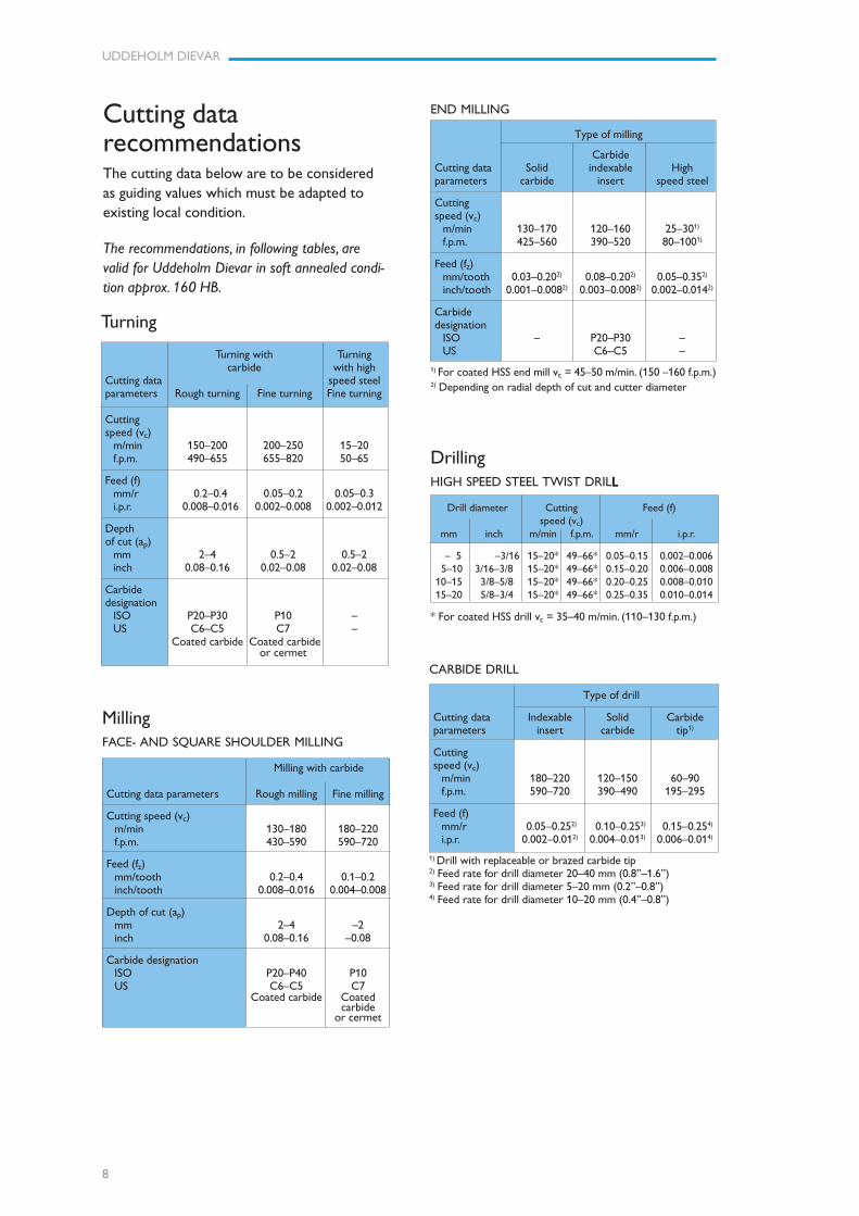
Turning
Turning with Turningcarbide with high
Cutting data speed steelparameters Rough turning Fine turning Fine turning
Cuttingspeed (vc)
m/min 150–200 200–250 15–20f.p.m. 490–655 655–820 50–65
Feed (f)mm/r 0.2–0.4 0.05–0.2 0.05–0.3i.p.r. 0.008–0.016 0.002–0.008 0.002–0.012
Depthof cut (ap)
mm 2–4 0.5–2 0.5–2inch 0.08–0.16 0.02–0.08 0.02–0.08
Carbidedesignation
ISO P20–P30 P10 –US C6–C5 C7 –
Coated carbide Coated carbideor cermet
MillingFACE- AND SQUARE SHOULDER MILLING
Milling with carbide
Cutting data parameters Rough milling Fine milling
Cutting speed (vc)m/min 130–180 180–220f.p.m. 430–590 590–720
Feed (fz)mm/tooth 0.2–0.4 0.1–0.2inch/tooth 0.008–0.016 0.004–0.008
Depth of cut (ap)mm 2–4 –2inch 0.08–0.16 –0.08
Carbide designationISO P20–P40 P10US C6–C5 C7
Coated carbide Coatedcarbide
or cermet
END MILLING
Type of milling
CarbideCutting data Solid indexable Highparameters carbide insert speed steel
Cuttingspeed (vc)
m/min 130–170 120–160 25–301)
f.p.m. 425–560 390–520 80–1001)
Feed (fz)mm/tooth 0.03–0.202) 0.08–0.202) 0.05–0.352)
inch/tooth 0.001–0.0082) 0.003–0.0082) 0.002–0.0142)
Carbidedesignation
ISO – P20–P30 –US C6–C5 –
1) For coated HSS end mill vc = 45–50 m/min. (150 –160 f.p.m.)2) Depending on radial depth of cut and cutter diameter
DrillingHIGH SPEED STEEL TWIST DRILLLLLL
Drill diameter Cutting Feed (f)speed (vc)
mm inch m/min f.p.m. mm/r i.p.r.
– 5 –3/16 15–20* 49–66* 0.05–0.15 0.002–0.006 5–10 3/16–3/8 15–20* 49–66* 0.15–0.20 0.006–0.00810–15 3/8–5/8 15–20* 49–66* 0.20–0.25 0.008–0.01015–20 5/8–3/4 15–20* 49–66* 0.25–0.35 0.010–0.014
* For coated HSS drill vc = 35–40 m/min. (110–130 f.p.m.)
CARBIDE DRILL
Type of drill
Cutting data Indexable Solid Carbideparameters insert carbide tip1)
Cuttingspeed (vc)
m/min 180–220 120–150 60–90f.p.m. 590–720 390–490 195–295
Feed (f)mm/r 0.05–0.252) 0.10–0.253) 0.15–0.254)
i.p.r. 0.002–0.012) 0.004–0.013) 0.006–0.014)
1) Drill with replaceable or brazed carbide tip2) Feed rate for drill diameter 20–40 mm (0.8”–1.6”)3) Feed rate for drill diameter 5–20 mm (0.2”–0.8”)4) Feed rate for drill diameter 10–20 mm (0.4”–0.8”)
Cutting datarecommendationsThe cutting data below are to be consideredas guiding values which must be adapted toexisting local condition.
The recommendations, in following tables, arevalid for Uddeholm Dievar in soft annealed condi-tion approx. 160 HB.
9
UDDEHOLM DIEVAR
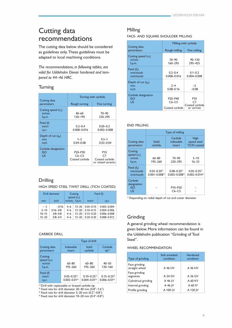
Turning
Turning with carbideCutting dataparameters Rough turning Fine turning
Cutting speed (vc)m/min 40–60 70–90f.p.m. 130–195 230–295
Feed (f)mm/r 0.2–0.4 0.05–0.2i.p.r. 0.008–0.016 0.002–0.008
Depth of cut (ap)mm 1–2 0.5–1inch 0.04–0.08 0.02–0.04
Carbide designationISO P20–P30 P10US C6–C5 C7
Coated carbide Coated carbideor mixed ceramic
DrillingHIGH SPEED STEEL TWIST DRILL (TICN COATED)
Drill diameter Cutting Feed (f)speed (vc)
mm inch m/min f.p.m. mm/r i.p.r.
– 5 –3/16 4–6 13–20 0.05–0.10 0.002–0.004 5–10 3/16–3/8 4–6 13–20 0.10–0.15 0.004–0.00610–15 3/8–5/8 4–6 13–20 0.15–0.20 0.006–0.00815–20 5/8–3/4 4–6 13–20 0.20–0.30 0.008–0.012
CARBIDE DRILL
Type of drill
Cutting data Indexable Solid Carbideparameters insert carbide tip1)
Cuttingspeed (vc)
m/min 60–80 60–80 40–50f.p.m. 195–260 195–260 130–160
Feed (f)mm/r 0.05–0.252) 0.10–0.253) 0.15–0.254)
i.p.r. 0.002–0.012) 0.004–0.013) 0.006–0.014)
1) Drill with replaceable or brazed carbide tip2) Feed rate for drill diameter 20–40 mm (0.8”–1.6”)3) Feed rate for drill diameter 5–20 mm (0.2”–0.8”)4) Feed rate for drill diameter 10–20 mm (0.4”–0.8”)
GrindingA general grinding wheel recommendation isgiven below. More information can be found inthe Uddeholm publication “Grinding of ToolSteel”.
WHEEL RECOMMENDATION
Soft annealed HardenedType of grinding condition condition
Face grindingstraight wheel A 46 HV A 46 HV
Face grindingsegments A 24 GV A 36 GV
Cylindrical grinding A 46 LV A 60 KV
Internal grinding A 46 JV A 60 IV
Profile grinding A 100 LV A 120 JV
END MILLING
Type of milling
Carbide HighCutting data Solid indexable speed steelparameters carbide insert TiCN coated
Cuttingspeed (vc)
m/min 60–80 70–90 5–10f.p.m. 195–260 230–295 16–33
Feed (fz)mm/tooth 0.03–0.201) 0.08–0.201) 0.05–0.351)
inch/tooth 0.001–0.0081) 0.003–0.0081) 0.002–0.0141)
Carbidedesignation
ISO – P10–P20 –US C6–C5 –
1) Depending on radial depth of cut and cutter diameter
MillingFACE- AND SQUARE SHOULDER MILLING
Milling with carbideCutting dataparameters Rough milling Fine milling
Cutting speed (vc)m/min 50–90 90–130f.p.m. 160–295 295–425
Feed (fz)mm/tooth 0.2–0.4 0.1–0.2inch/tooth 0.008–0.016 0.004–0.008
Depth of cut (ap)mm 2–4 –2inch 0.08–0.16 –0.08
Carbide designationISO P20–P40 P10US C6–C5 C7
Coated carbideCoated carbide or cermet
Cutting datarecommendationsThe cutting data below should be consideredas guidelines only. These guidelines must beadapted to local machining conditions.
The recommendations, in following tables, arevalid for Uddeholm Dievar hardened and tem-pered to 44–46 HRC.
10
UDDEHOLM DIEVAR
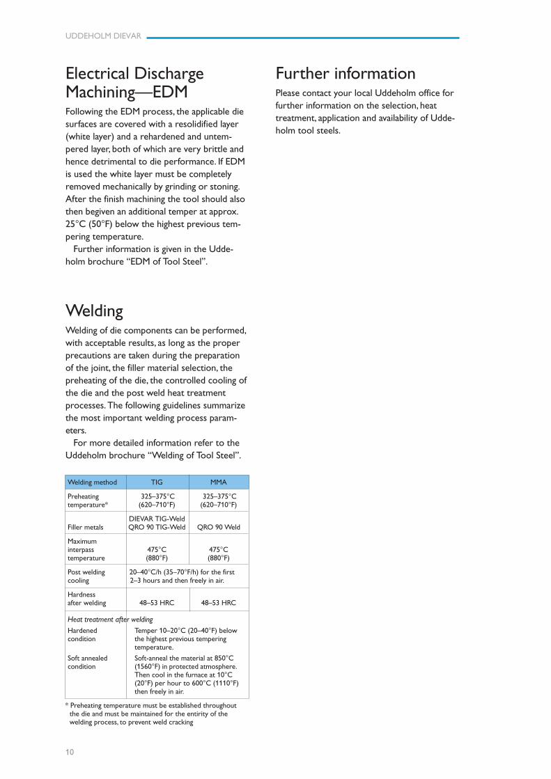
WeldingWelding of die components can be performed,with acceptable results, as long as the properprecautions are taken during the preparationof the joint, the filler material selection, thepreheating of the die, the controlled cooling ofthe die and the post weld heat treatmentprocesses. The following guidelines summarizethe most important welding process param-eters.
For more detailed information refer to theUddeholm brochure “Welding of Tool Steel”.
Electrical DischargeMachining—EDMFollowing the EDM process, the applicable diesurfaces are covered with a resolidified layer(white layer) and a rehardened and untem-pered layer, both of which are very brittle andhence detrimental to die performance. If EDMis used the white layer must be completelyremoved mechanically by grinding or stoning.After the finish machining the tool should alsothen begiven an additional temper at approx.25°C (50°F) below the highest previous tem-pering temperature.
Further information is given in the Udde-holm brochure “EDM of Tool Steel”.
Further informationPlease contact your local Uddeholm office forfurther information on the selection, heattreatment, application and availability of Udde-holm tool steels.
* Preheating temperature must be established throughout the die and must be maintained for the entirity of the welding process, to prevent weld cracking
Welding method TIG MMA
Preheating 325–375°C 325–375°Ctemperature* (620–710°F) (620–710°F)
DIEVAR TIG-WeldFiller metals QRO 90 TIG-Weld QRO 90 Weld
Maximuminterpass 475°C 475°Ctemperature (880°F) (880°F)
Post welding 20–40°C/h (35–70°F/h) for the firstcooling 2–3 hours and then freely in air.
Hardnessafter welding 48–53 HRC 48–53 HRC
Heat treatment after welding
Hardened Temper 10–20°C (20–40°F) belowcondition the highest previous tempering
temperature.
Soft annealed Soft-anneal the material at 850°Ccondition (1560°F) in protected atmosphere.
Then cool in the furnace at 10°C(20°F) per hour to 600°C (1110°F)then freely in air.
www.assab.com www.uddeholm.com
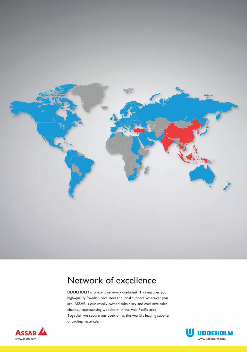
Network of excellenceUDDEHOLM is present on every continent. This ensures you
high-quality Swedish tool steel and local support wherever you
are. ASSAB is our wholly-owned subsidiary and exclusive sales
channel, representing Uddeholm in the Asia Pacific area.
Together we secure our position as the world’s leading supplier
of tooling materials.
UD
DEH
OLM
120310.300 / TRYC
KERI KNA
PPEN, KA
RLSTAD
201203168
UDDEHOLM is the world’s leading supplier of tooling materials. This
is a position we have reached by improving our customers’ everyday
business. Long tradition combined with research and product develop-
ment equips Uddeholm to solve any tooling problem that may arise.
It is a challenging process, but the goal is clear – to be your number one
partner and tool steel provider.
Our presence on every continent guarantees you the same high quality
wherever you are. ASSAB is our wholly-owned subsidiary and exclusive
sales channel, representing Uddeholm in the Asia Pacific area.
Together we secure our position as the world’s leading supplier of
tooling materials. We act worldwide, so there is always an Uddeholm or
ASSAB representative close at hand to give local advice and support.
For us it is all a matter of trust – in long-term partnerships as well as in
developing new products. Trust is something you earn, every day.
For more information, please visit www.uddeholm.com, www.assab.com
or your local website.