Embed Size (px)
Citation preview

UDC3300Universal DigitalLimit Controller
51-52-25-1011/01

ii UDC3300 Limit Controller Product Manual 1/01
About This Document
AbstractThis Product Manual is divided into 9 sections numbered 1 through 9. These sections contain all the information youneed to configure, operate, monitor, and troubleshoot your controller.
To find information quickly, use the comprehensive Table of Contents in the front of the manual and the Index locatedin the back of the manual.

1/01 UDC3300 Limit Controller Product Manual iii
Symbol DefinitionsThe following table lists those symbols that may be used in this document to denote certain conditions.
Symbol Definition
This DANGER symbol indicates an imminently hazardous situation, which, ifnot avoided, will result in death or serious injury.
This WARNING symbol indicates a potentially hazardous situation, which, ifnot avoided, could result in death or serious injury.
This CAUTION symbol may be present on Control Product instrumentationand literature. If present on a product, the user must consult the appropriatepart of the accompanying product literature for more information.
This CAUTION symbol indicates a potentially hazardous situation, which, ifnot avoided, may result in property damage.
WARNINGPERSONAL INJURY: Risk of electrical shock. This symbol warns the user of apotential shock hazard where HAZARDOUS LIVE voltages greater than 30 Vrms,42.4 Vpeak, or 60 Vdc may be accessible. Failure to comply with theseinstructions could result in death or serious injury.
ATTENTION, Electrostatic Discharge (ESD) hazards. Observe precautions forhandling electrostatic sensitive devices
Protective Earth (PE) terminal. Provided for connection of the protective earth(green or green/yellow) supply system conductor.
Functional earth terminal. Used for non-safety purposes such as noise immunityimprovement. NOTE: This connection shall be bonded to protective earth at thesource of supply in accordance with national local electrical code requirements.
Earth Ground. Functional earth connection. NOTE: This connection shall be bondedto Protective earth at the source of supply in accordance with national and localelectrical code requirements.
Chassis Ground. Identifies a connection to the chassis or frame of the equipmentshall be bonded to Protective Earth at the source of supply in accordance withnational and local electrical code requirements.

iv UDC3300 Limit Controller Product Manual 1/01
Table of Contents
SECTION 1 – OVERVIEW ..................................................................................................1
1.1 Introduction ...................................................................................................11.2 Operator Interface.........................................................................................3
SECTION 2 – INSTALLATION ...........................................................................................5
2.1 Overview.......................................................................................................52.2 Model Number Interpretation ........................................................................72.3 Mounting .......................................................................................................82.4 Wiring..........................................................................................................102.5 Wiring Diagrams .........................................................................................12
SECTION 3 – CONFIGURATION .....................................................................................19
3.1 Overview.....................................................................................................193.2 Configuration Prompts ................................................................................203.3 How To Get Started ....................................................................................213.4 Configuration Tips.......................................................................................223.5 Configuration Procedure .............................................................................233.6 Lockout Set Up Group ................................................................................253.7 Limit Set Up Group .....................................................................................263.8 Input 1 Parameters Set Up Group ..............................................................273.9 Communications Set Up Group ..................................................................293.10 Alarms Set Up Group..................................................................................303.11 Calib Group.................................................................................................313.12 Status Group...............................................................................................313.13 Configuration Record Sheet........................................................................32
SECTION 4 – CONFIGURATION PROMPT DEFINITIONS.............................................33
4.1 Overview.....................................................................................................334.2 Lockout Data Set Up Group........................................................................344.3 Limit Data Set Up Group.............................................................................354.4 Input 1 Parameters Set Up Group ..............................................................364.5 Communications Set Up Group ..................................................................404.6 Alarms Set Up Group..................................................................................424.7 Calibration Data ..........................................................................................444.8 Status Test Data .........................................................................................44
SECTION 5 – OPERATION ..............................................................................................45
5.1 Overview.....................................................................................................455.2 How to Power Up the Controller .................................................................465.3 Enter a Security Code.................................................................................485.4 How to Operate Your Limit Controller .........................................................495.5 How to Monitor Your Limit Controller ..........................................................525.6 Alarm Setpoints...........................................................................................545.7 Restarting After Power Loss .......................................................................55
SECTION 6 – INPUT CALIBRATION...............................................................................57
6.1 Overview.....................................................................................................576.2 Minimum and Maximum Range Values ......................................................586.3 Preliminary Information ...............................................................................59

1/01 UDC3300 Limit Controller Product Manual v
6.4 Input #1 Set Up Wiring ............................................................................... 616.5 Input #1 Calibration Procedure................................................................... 67
SECTION 7 – TROUBLESHOOTING / SERVICE............................................................ 69
7.1 Overview .................................................................................................... 697.2 Troubleshooting Aids.................................................................................. 717.3 Power-up Tests .......................................................................................... 737.4 Status Tests ............................................................................................... 747.5 Background Tests ...................................................................................... 767.6 Controller Failure Symptoms...................................................................... 787.7 Troubleshooting Procedures ...................................................................... 797.8 Parts Replacement Procedures ................................................................. 837.9 Maintenance............................................................................................... 92
SECTION 8 – PARTS LIST .............................................................................................. 93
8.1 Exploded View............................................................................................ 938.2 Parts Not Shown ........................................................................................ 94
SECTION 9 – APPENDIX A – HOW TO APPLY DIGITAL INSTRUMENTATION INSEVERE ELECTRICAL NOISE ENVIRONMENTS................................... 95
9.1 Overview .................................................................................................... 959.2 Potential Noise Sources ............................................................................. 969.3 Prevention Methods ................................................................................... 979.4 Recommended Wiring Practices ................................................................ 989.5 Power Source Considerations.................................................................. 1009.6 Noise Suppression at the Source............................................................. 101

vi UDC3300 Limit Controller Product Manual 1/01
Figures
Figure 1-1 Operator Interface Displays and Indicators ...............................................3Figure 2-1 Model Number Interpretation.....................................................................7Figure 2-2 Dimensions................................................................................................8Figure 2-3 Mounting Method.......................................................................................9Figure 2-4 Composite Wiring Diagram......................................................................12Figure 2-5 Line Voltage Wiring..................................................................................13Figure 2-6 Input #1 Connections...............................................................................14Figure 2-7 Output and Alarm Wiring .........................................................................15Figure 2-8 Digital Input Connections.........................................................................16Figure 2-9 RS422/485 Communications Option Connections ..................................17Figure 2-10 DMCS Communications Option Connections..........................................18Figure 3-1 Overview of UDC3300 Prompt Hierarchy................................................20Figure 5-1 Operator Interface ...................................................................................49Figure 6-1 Input #1 Wiring Terminals........................................................................59Figure 6-2 Wiring Connections for Thermocouple Inputs Using an Ice Bath ............61Figure 6-3 Wiring Connections for Thermocouple Inputs Using a Precision
Resistor....................................................................................................62Figure 6-4 Wiring Connections for RTD (Resistance Thermometer Device) ............63Figure 6-5 Wiring Connections for Radiamatic, Millivolts, or Volts
(except 0 to 10 Volts)...............................................................................64Figure 6-6 Wiring Connections for 0 to 10 Volt Inputs .............................................65Figure 6-7 Wiring Connections for 4 to 20 mA Inputs ..............................................66Figure 7-1 Chassis Removal.....................................................................................84Figure 7-2 Display/Keyboard Replacement ..............................................................85Figure 7-3 Removing the Printed Wiring Boards.......................................................86Figure 7-4 Printed Wiring Board Identification ..........................................................87Figure 8-1 UDC3300 Exploded View ........................................................................93Figure 9-1 Transformer for Digital Equipment.........................................................100Figure 9-2 Transient Suppression in Inductive Coils...............................................102Figure 9-3 Contact Noise Suppression ...................................................................103Figure 9-4 DC Load Noise Suppression .................................................................104

1/01 UDC3300 Limit Controller Product Manual vii
Tables
Table 1-1 Function of Keys ....................................................................................... 4Table 2-1 Operating Limits ........................................................................................ 6Table 2-2 Permissible Wiring Bundling.................................................................... 10Table 3-1 Configuration Tips ................................................................................... 22Table 3-2 Configuration Procedure ......................................................................... 23Table 3-3 Lockout Group Function Prompts ........................................................... 25Table 3-4 Limit Group Function Prompts ................................................................ 26Table 3-5 Input 1 Group Function Prompts ............................................................. 27Table 3-6 Com Group Function Prompts ................................................................ 29Table 3-7 Alarms Group Function Prompts............................................................. 30Table 4-1 Lockout Group Prompt Definitions .......................................................... 34Table 4-2 Limit Group Prompt Definitions ............................................................... 35Table 4-3 Input 1 Group Definitions ........................................................................ 36Table 4-4 Communications Group Definitions......................................................... 40Table 4-5 Alarms Group Definitions ........................................................................ 42Table 5-1 Power Up Diagnostic Tests..................................................................... 46Table 5-2 Procedure for Testing the Displays and Keys ......................................... 47Table 5-3 Procedure for Entering a Security Code ................................................. 48Table 5-4 Limit Action Duration or Peak PV Value.................................................. 50Table 5-5 Change a Setpoint Value Procedure....................................................... 51Table 5-6 Error Messages....................................................................................... 52Table 5-7 Procedure for Displaying or Changing the Alarm Setpoints.................... 54Table 6-1 Voltage and Resistance Equivalents for 0% and 100% Range Values... 58Table 6-2 Equipment Needed ................................................................................. 60Table 6-3 Set Up Wiring Procedure for Thermocouple Inputs Using An Ice Bath... 61Table 6-4 Set Up Wiring Procedure for Thermocouple Inputs Using a
Precision Resistor ................................................................................... 62Table 6-5 Input #1 Calibration Procedure ............................................................... 67Table 7-1 Error Message Prompts .......................................................................... 71Table 7-2 Procedure for Identifying the Software Version....................................... 72Table 7-3 Power-up Tests ....................................................................................... 73Table 7-4 Procedure for Displaying the Status Tests Results................................. 74Table 7-5 Status Tests ............................................................................................ 75Table 7-6 Background Tests ................................................................................... 76Table 7-7 Controller Failure Symptoms................................................................... 78Table 7-8 Troubleshooting Power Failure Symptoms ............................................. 79Table 7-9 Troubleshooting Latching Output Relay Failure...................................... 80Table 7-10 Troubleshooting Alarm Relay Output Failure .......................................... 80Table 7-11 Troubleshooting a Keyboard Failure ....................................................... 81Table 7-12 Troubleshooting a Communications Failure............................................ 82Table 7-13 How to Remove the Chassis................................................................... 84Table 7-14 Display/Keyboard Assembly Replacement Procedure............................ 85Table 7-15 Printed Wiring Board Removal from Chassis.......................................... 86Table 7-16 Power Input Board Replacement Procedure........................................... 88Table 7-17 Digital Input Board Replacement Procedure........................................... 89Table 7-18 Communications Board Replacement Procedure ................................... 90Table 7-19 MCU/Output Board Replacement Procedure.......................................... 91Table 8-1 Parts Identification................................................................................... 94Table 8-2 Parts Not Shown ..................................................................................... 94Table 9-1 External Wiring........................................................................................ 98Table 9-2 MOV Devices ........................................................................................ 101Table 9-3 Coil Voltage vs Resistor Voltage Rating................................................ 102

viii UDC3300 Limit Controller Product Manual 1/01
Acronyms
DMCS ................................................................. Distributed Manufacturing Control SystemEMI ..........................................................................................Electromagnetic interferenceHID...................................................................................................High intensity dischargeIEEE............................................................ Institute of Electrical and Electronics EngineersMOVs.................................................................................................. Metal Oxide VaristorsNC................................................................................................................ Normally closedNO ..................................................................................................................Normally openRC....................................................................................................Resistance-capacitanceRFI ...........................................................................................Radio frequency interferenceRH..............................................................................................................Relative HumidityRS422...........................................................................................Communications ProtocolRTD ................................................................................. Resistance Thermometer DeviceSCRs ........................................................................................... Silicon controlled rectifiersUDC............................................................................................ Universal Digital Controller

1/01 UDC3300 Limit Controller Product Manual ix
Parameters
A1S1 HL........................................................................................ Alarm 1, Setpoint 1 StateA1S1 VAL................................................................................................Alarm 1, Setpoint 1A1S1TYPE .....................................................................................Alarm 1, Setpoint 1 TypeA1S2 HL........................................................................................ Alarm 1, Setpoint 2 StateA1S2 VAL................................................................................................Alarm 1, Setpoint 2A1S2TYPE .....................................................................................Alarm 1, Setpoint 2 TypeA2S1 HL........................................................................................ Alarm 2, Setpoint 1 StateA2S1 VAL................................................................................................Alarm 2, Setpoint 1A2S1TYPE ..............................................................................................Alarm 2, Setpoint 1A2S2 HL........................................................................................ Alarm 2, Setpoint 2 StateA2S2 VAL................................................................................................Alarm 2, Setpoint 2A2S2TYPE .....................................................................................Alarm 2, Setpoint 2 TypeAL HYST .................................................................................................... Alarm HysteresisBAUD ................................................................................................................... Baud RateBIAS IN1 ............................................................................................................ Input 1 BiasCAL TEST ...........................................................................................Calibration test failureCom ADDR ...................................................................... Communications Station AddressComSTATE ............................................................................Communications Option StateCONFTEST.................................................................................... Configuration test failureDUPLEX.................................................................................................... Duplex OperationE E FAIL...................................................................Unable to write to non-volatile memoryEMSSIV................................................................................................................. EmissivityEXT RSET............................................................................ External Reset (Digital Input 1)FACT CRC........................................................Factory Calibration Cyclic Redundancy testFAILSAFE ............................................................................................ Controller in FailsafeFILTER 1........................................................................................................... Input 1 FilterIN1 HI ........................................................................................... Input 1 High Range ValueIN1 LO.......................................................................................... Input 1 Low Range ValueIN1 TYPE .......................................................................................... Input 1 Actuation TypeINP1 RNG ............................................................................................ Input 1 Out of RangeINP1FAIL...................................................... Two consecutive failures of Input 1 integrationLO or HI................................................................................................ Type of Limit ControlLOOPBACK ................................................................................................Local Loop BackPARITY ........................................................................................................................ ParityPOWER UP.................................................................................................. Power-up LogicPV LIMIT .................................................................................................... PV Out of RangePWR FREQ....................................................................................... Power Line FrequencyRAM TEST ....................................................................................................RAM test failedSHEDTIME...........................................................................................................Shed TimeSP HILIM................................................................................................. High Setpoint LimitSP LOLIM.................................................................................................Low Setpoint LimitUNITS ................................................................................................. Communication UnitsXMITTER .................................................................................Transmitter Characterization

x UDC3300 Limit Controller Product Manual 1/01

1/01 UDC3300 Limit Controller Product Manual 1
Section 1 – Overview
1.1 Introduction
Function The UDC3300 Universal Digital Limit Controller is a microprocessor-based stand-alone controller. It combines the highest degree offunctionality and operating simplicity offered in a 1/4 DIN size controller.
With a typical accuracy of ±0.20% of span, the UDC3300 is an idealcontroller for limiting temperature and other process variables innumerous heating and cooling applications, in metal working, food, andpharmaceuticals, and testing and environmental work.
Easy to read displays The dedicated vacuum fluorescent displays with English prompts makethe operator interface easy to read, understand and operate.Programmed sequences of displays assure quick and accurate entry of allconfigurable parameters.
Easy to operate Simple keystrokes let you select input and range configuration, set theoperating parameters that meet your process control needs now, andchange them later to meet new ones.
The tactile keyboard provides positive operator feedback. Self diagnostics,fault tolerant design and keyboard security provide maximum assurance oftrouble-free operation.
Latching relays This limit controller has a latching output relay which is de-energizedwhenever the PV goes above (high limit) or below (low limit) a selectedsetpoint value. When the limit is exceeded (high or low), the lower displayalternately indicates “the limit control setpoint value” and the word“limit.”
Reset of relay Reset of the latching output relay is made through a [RESET] key on thefront of the controller or an external switch (if the option is present).
Alarm relay Two additional non-latching alarm relays with two setpoints each alertyou to critical process conditions.
Continued on next page

2 UDC3300 Limit Controller Product Manual 1/01
1.1 Introduction, Continued
Mount anywhere The UDC is industrial control equipment that must be panel mounted.The wiring terminals must be enclosed within the panel. The UDC isenvironmentally hardened and, when suitably enclosed, can be mountedvirtually anywhere in plant or factory; on the wall, in a panel, or even onthe process machine. It withstands ambient temperatures up to 55 °C(133 °F) and resists the effects of vibration and mechanical shock.
CE Conformity(Europe)
This product is in conformity with the protection requirements of thefollowing European Council Directives: 73/23/EEC, the Low VoltageDirective, and 89/336/EEC, the EMC Directive. Conformity of thisproduct with any other “CE Mark” Directive(s) shall not be assumed.
Deviation from the installation conditions specified in this manual, and thespecial conditions for CE conformity in Section 2.1, may invalidate thisproduct’s conformity with the Low Voltage and EMC Directives.
ATTENTION
The emission limits of EN 50081-2 are designed to provide reasonable protection against harmfulinterference when this equipment is operated in an industrial environment. Operation of this equipmentin a residential area may cause harmful interference. This equipment generates, uses, and can radiateradio frequency energy and may cause interference to radio and television reception when theequipment is used closer than 30 meters (98 feet) to the antenna(e). In special cases, when highlysusceptible apparatus is used in close proximity, the user may have to employ additional mitigatingmeasures to further reduce the electromagnetic emissions of this equipment.

1/01 UDC3300 Limit Controller Product Manual 3
1.2 Operator Interface
Displays andindicators
Figure 1-1 shows the operator interface and defines the displays andindicators. The function of the keys is shown in Table 1-1.
Figure 1-1 Operator Interface Displays and Indicators
Upper Display - Six Characters • Normal Operation - four digits dedicated to display the process variable, or blank • Configuration Mode - displays parameter value or selection
Lower Display - Eight characters • Normal Operation - displays the value of limit control setpoint, or indicates "LIMIT OK". When alarm condition exists, it alternates between the setpoint value and the word "LIMIT". • Configuration Mode - displays function group and parameters
ALM
DI
RSP
OUT
1
1
1 2 F C
FUNCTION
SET UP
LOWER DISPLAY
Indicator definition when lit
ALM - Alarm conditions exist
DI - Digital Input active
F - °Fahrenheit being used
C - °Centigrade being used
Keys - See Table 1-1
RESET
22642
Continued on next page

4 UDC3300 Limit Controller Product Manual 1/01
1.2 Operator Interface, Continued
Function of keys Table 1-1 shows each key on the operator interface and defines itsfunction.
Table 1-1 Function of Keys
Key Function
SET UP• Places the controller in the Configuration Set Up group select
mode. Sequentially displays Set Up groups and allows the[FUNCTION] key to display individual functions in each Set Upgroup.
FUNCTION• Used in conjunction with the [SET UP] key to select the individual
functions of a selected Configuration Set Up group.
• Used during field calibration procedure.
LOWER DISPLAY
• Selects one of the following display modes when no limitconditions exist:
#1 Upper Display = the value of the process variableLower Display = the value of the Limit Control Setpoint
#2 Upper Display = (blank) except during Limit conditionsLower Display = the value of the Limit Control Setpoint
#3 Upper Display = (blank)except during Limit conditionsLower Display = LIMIT OK
• Pressing [LOWER DISPLAY] key while a limit condition exists,shows the following in the lower display:
TIME XX.YY = Limit action duration in hours and minutes
PK_XXXXX = Peak PV Value—The highest PV value reached fora High Limit Controller, or the lowest PV valuereached for a Low Limit Controller.
RESET• Resets the latching output relay. Relay cannot be reset while a
limit condition exists.
The upper blank key is not used.
The lower blank key restores an original value.
– When you are using the [FUNCTION] key and [s] [t] keys tochange a parameter value of selection and you decide you wantto keep the original value that was displayed, press the lowerblank key, before entry, to recall the original value.
• Increases the setpoint, output, or configuration values displayed.
• Decreases the setpoint, output, or configuration values displayed.

1/01 UDC3300 Limit Controller Product Manual 5
Section 2 – Installation
2.1 Overview
Introduction Installation of the UDC3300 Limit Controller consists of mounting andwiring the controller according to the instructions given in this section.
Read the pre-installation information, check the model numberinterpretation and become familiar with your model selections, thenproceed with installation.
What’s in thissection?
This section contains the following information:
Topic See Page
2.1 Overview2.2 Model Number Interpretation2.3 Mounting
Physical ConsiderationsOverall DimensionsMounting Procedure
2.4 WiringTaking Electrical Noise PrecautionsPermissible Wire BundlingIdentify Your Wiring RequirementsControl Alarm Circuit WiringWiring the Controller
2.5 Wiring DiagramsComposite Wiring DiagramAC Line VoltageInput #1Output and Alarm WiringDigital InputsCommunications
RS422/485DMCS
578889101010111111121213141516171718
Pre-installationinformation
If the controller has not been removed from its shipping carton, inspect thecarton for damage and remove the controller. Inspect the unit for anyobvious shipping damage and report any damage due to transit to thecarrier.
Make sure the carton with the controller includes
• a bag containing mounting hardware and
• a bag containing input resistors.
Check that the model number shown on the inside of the case agrees withwhat you have ordered.
Continued on next page

6 UDC3300 Limit Controller Product Manual 1/01
2.1 Overview, Continued
CE Conformityspecial conditions(Europe)
Shielded twisted pair cables are required for all Analog I/O, ProcessVariable, RTD, Thermocouple, dc millivolt, low level signal, 4-20 mA,Digital I/O, and computer interface circuits.
Operating limits We recommend that you review and adhere to the operating limits listed inTable 2-1 when you install your controller.
Table 2-1 Operating Limits
Condition Specifications
Ambient Temperature 32 to 131°F (0 to 55°C)
Relative Humidity 5 to 90 % RH at 40°C (104°F)
VibrationFrequencyAcceleration
0 to 200 Hz0.6 g
Mechanical ShockAccelerationDuration
5 g30 ms
Power90 to 264 Vac
24 Vac/dc
90 to 264 Vac 50/60 Hz (CSA models rated to 250 V maximum)
20 to 27 Vac 50/60 Hz20 to 27 Vdc 0 Hz
Power Consumption 18 VA maximum (90 to 264 Vac)12 VA maximum (24 Vac/dc)
Frequency(For Vac)
48 to 52 Hz58 to 62 Hz

1/01 UDC3300 Limit Controller Product Manual 7
2.2 Model Number Interpretation
Model number The model number interpretation is shown in Figure 2-1. Write the modelnumber into the spaces provided and compare it to the model numberinterpretation. This information will also be useful when you wire yourcontroller.
Figure 2-1 Model Number Interpretation
0D C 3 3 0Table VITable VTable IVTable IIITable IITable IKey Number
Output #1 E – = Output #2 or Alarm #2 – 0 = – E =
Limit Control Model
Relay, Electromechanical None Relay, Electromechanical
External Interface 0 – – = 1 – – = Digital Inputs – – 0 = – – 3 =
None RS422/485 ASCII None One Digital Input
PV Input 1 – = 2 – = 3 – =
T/C, RTD, Radiamatic, mV, 0-5V, 1-5V T/C, RTD, Radiamatic, mV, 0-5V, 1-5V, 0-20 mA, 4-20 mA T/C, RTD, Radiamatic, mV, 0-5V, 1-5V, 0-20 mA, 4-20 mA, 0-10V
Options 0 – – – – – =1 – – – – – = – 0 – – – – =
– F – – – – = – – 0 – – – = – – B – – – = – – T – – – = – – – 0 – – =
– – – T – – =
– – – – 0 – = – – – – D – = – – – – – 0 =
90 to 264 Vac Power 24 Vac/dc Power None
FM and UL* Gray Elastomer Bezel Blue Elastomer Bezel Tan Elastomer Bezel None
Customer ID Tag
None DIN Cutout Adapter None
Certificate – 0 = – C =
None Certificate of Conformance
L 0 0 0
*FM approved Limit Controllers are restricted to thermocouple and RTD PV inputs. Limit Controllers are UL recognized for regulatory use only.
– A – – – – = CSA, FM and UL*
– – – P – – = Rear Terminal Cover
– – – U – – = Rear Terminal Cover and Tag

8 UDC3300 Limit Controller Product Manual 1/01
2.3 Mounting
Physicalconsiderations
The controller can be mounted on either a vertical or tilted panel using themounting kit supplied. Adequate access space must be available at theback of the panel for installation and servicing activities.
The overall dimensions and panel cutout requirements for mounting thecontroller are shown in Figure 2-2.
Overall dimensions Figure 2-2 shows the overall dimensions for mounting the controller.
Figure 2-2 Dimensions
Panel Cutout
LALM
RSP
OUT
%
1 2
1 2 F C MAN PV 1 2 3 4
96 3.780
96 3.780
LALM %1
2 1 2
1 2
F C
MAN
DI
ALM
%
1 2 F C
DI
FUNCTION LOWER DISPLAY
RESET
SET UP
1
24.945
Max PanelThickness 10
.394Max (2)
5.82147.3
21.6.850
.0932.4 with optional
rear cover
90.73.57
22716
+0.8 92 3.622 +0.03
-0.0
-0.0
+0.8 92 3.622 +0.03
-0.0
-0.0
Continued on next page

1/01 UDC3300 Limit Controller Product Manual 9
2.3 Mounting, Continued
Mounting method Before mounting the controller, refer to the nameplate on the inside of thecase and make a note of the model number. It will help later whenselecting the proper wiring configuration.
Figure 2-3 shows you the mounting method for the UDC3300 Limitcontroller.
Figure 2-3 Mounting Method
Panel
22605
Mounting procedure Refer to Figure 2-3 and follow the procedure below to mount thecontroller.
Step Action
1 Mark and cut out the controller hole in the panel according to the dimensioninformation in Figure 2-2.
2 Remove the screw cover and loosen the screw on the front of the controller.Pull the chassis out of the case.
3 Orient the case properly and slide it through the panel hole from the front.
4 Remove the mounting kit from the shipping container, and install the kit asfollows:• Install the screws into the threaded holes of the clips.• Insert the prongs of the clips into the two holes in the top and
bottom of the case.• Tighten both screws to secure the case against the panel.• Carefully slide the chassis assembly into the case, press to close and
tighten the screw. Replace the screw cover.

10 UDC3300 Limit Controller Product Manual 1/01
2.4 Wiring
Electricalconsiderations
The controller is considered “rack and panel mounted equipment” perEN 61010-1, Safety Requirements for Electrical Equipment forMeasurement, Control, and Laboratory Use, Part 1: GeneralRequirements. Conformity with 72/23/EEC, the Low Voltage Directiverequires the user to provide adequate protection against a shock hazard.The user shall install this controller in an enclosure that limitsOPERATOR access to the rear terminals.
Controller grounding PROTECTIVE BONDING (grounding) of this controller and theenclosure in which it is installed shall be in accordance with National andlocal electrical codes. To minimize electrical noise and transients that mayadversely affect the system, supplementary bonding of the controllerenclosure to a local ground, using a No. 12 (4 mm2) copper conductor, isrecommended.
Taking electrical noiseprecautions
Electrical noise is composed of unabated electrical signals which produceundesirable effects in measurements and control circuits.
Digital equipment is especially sensitive to the effects of electrical noise.Your controller has built-in circuits to reduce the effect of electrical noisefrom various sources. If there is a need to further reduce these effects:
• Separate External Wiring - separate connecting wires into bundles(see Table 2-2) and route the individual bundles through separateconduits or metal trays.
• Use Suppression Devices - for additional noise protection, you maywant to add suppression devices at the external source. Appropriatesuppression devices are commercially available.
NOTE For additional noise information, refer to Section 9.
Permissible wirebundling
Table 2-2 shows which wire functions should be bundled together.NOTE For installation where high EMI/RFI noise cannot be avoided, we
recommend you use shielded twisted pair wires for the signals in bundle 2.
Table 2-2 Permissible Wiring Bundling
Bundle No. Wire Functions
1 • Line power wiring• Earth ground wiring• Control relay output wiring• Line voltage alarm wiring
2 Analog signal wire, such as:• Input signal wire (thermocouple, 4 to 20 mA, etc.)• Digital input signals• Communications
3 • Low voltage alarm relay output wiring• Low voltage wiring to solid state type control circuits
Continued on next page

1/01 UDC3300 Limit Controller Product Manual 11
2.4 Wiring, Continued
Alarm circuit wiring The insulation of wires connected to the Alarm terminals shall be rated forthe highest voltage involved. Extra Low Voltage (ELV) wiring (input,current output, and low voltage Alarm circuits) shall be separated fromHAZARDOUS LIVE (>30 Vac, 42.4 Vpeak, or 60 Vdc) wiring per Table2-2.
Identify your wiringrequirements
To determine the appropriate diagrams for wiring your controller, refer tothe model number interpretation in this section. The model number of thecontroller can be found on the inside of the case.
Wiring the controller Using the information contained in the model number, select theappropriate wiring diagrams from the figures listed below and wire thecontroller accordingly.
Wiring Requirements Figure
Composite Wiring Diagram 2-4
Line Power 90–264 Vac or 24 Vac/dc 2–5
Input #1 Wiring 2–6
Output and Alarm Wiring 2-7
Digital Inputs Wiring 2–8
Communications Wiring• RS422• DMCS
2–92–10

12 UDC3300 Limit Controller Product Manual 1/01
2.5 Wiring Diagrams
Composite wiringdiagram
Figure 2-4 is a composite wiring diagram of the UDC3300 Limitcontroller. It identifies the terminal designations and their functions. Referto the individual diagrams listed to wire the controller according to yourrequirements.
Figure 2-4 Composite Wiring Diagram
1
2
3
4
5
6
7
8
9
L1
L2/N
22
23
24
25
26
27
CommunicationsTerminals
See Figures 2-9 and 2-10
Outputs and Alarms Terminals
See Figure 2-7
Digital InputTerminals
See Figure 2-8
AC Line VoltageTerminals
See Figure 2-5
Input #1Terminals
See Figure 2-6
10
11
12
13
14
15
16
17
I/O Shield Ground (Do Not use for communication shield)
Continued on next page

1/01 UDC3300 Limit Controller Product Manual 13
2.5 Wiring Diagrams, Continued
Line voltage wiring This equipment is suitable for connection to 90-264 Vac or 24 Vac/dc,50/60 Hz, power supply mains. It is the user’s responsibility to provide aswitch and non-time delay (North America), quick-acting, high breakingcapacity, Type F, (Europe) 1/2 A, 250 V fuse(s) or circuit-breaker for 90-264 V; or 1 A, 125 V fuse or circuit breaker for 24Vac/dc operation, aspart of the installation. The switch or circuit-breaker should be locatedclose to the controller, within easy reach of the operator. The switch orcircuit-breaker should be marked as the disconnecting device for thecontroller. (4mm2).
CAUTION Applying 90-264 Vac to a controller rated for 24Vac/dcwill severely damage the controller and is a fire and smoke hazard.
When applying power to multiple instruments, make sure that sufficientcurrent is supplied. Otherwise, the instruments may not start up normallydue to the voltage drop caused by the in-rush current.
Figure 2-5 shows the wiring connections for line voltage.
Figure 2-5 Line Voltage Wiring
1
2
3
4
5
6
7
8
9
10
11
12
13
14
15
16
17
L1
L2/N
22
23
24
25
26
27
Ground
Hot
NeutralAC/DC Line
Voltage
PROTECTIVE BONDING (grounding) of this controller and the enclosure in which it is installed, shall be in accordance with National and local electrical codes. To minimize electrical noise and transients that may adversly affect the system, supplementary bonding of the controller enclosure to a local ground, using a No. 12 (4 mm
1
2
1
2
22607
2) copper conductor, is recommended.
Provide a switch and non-time delay (North America), quick-acting, high breaking capacity, Type F, (Europe) 1/2 A, 250 V fuse(s) or circuit-breaker for 90-264 V; or 1 A, 125 V fuse or circuit breaker for 24 Vac/dc operation, as part of the installation.
Continued on next page

14 UDC3300 Limit Controller Product Manual 1/01
2.5 Wiring Diagrams, Continued
Input #1 connections Figure 2-6 shows the wiring connections for Input #1.
Figure 2-6 Input #1 Connections
1
2
3
4
5
6
7
8
9
10
11
12
13
14
15
16
17
L1
L2/N
22
23
24
25
26
27
R
+–
I N P U T 1
25
26
27
Use Thermocouple extension wire only
Thermocouple
25
26
27
RTD
25
26
27
MV or Volts except 0 –10 Volts
MV or Volt source
25
26
27
0 –10 Volts
25
26
27
+
–
4–20 milliamps
R
–
+Power
Supply –+
Xmitter
+
–
250 Ω
+
–
1
2
3–
0–10 Volt
source
+
+
–
RR
+
R
–
R
+
–
100K
100K
The 250Ω load resistor for 4-20mA or the Voltage divider for 0–10 Volts or the 500 Ohm C/J compensation resistor are supplied with the controller when the input is specified. These items must be installed when you wire the controller before startup.
1
1
1
1
Remove screw and install C/J on the "R" terminal, connect tang to "–" terminals. 2
2 When installing the cold junction (Part number 30757088-001) for a T/C input, remove the screws from terminals 25 and 27, and install the assembly into place.
22608
Continued on next page

1/01 UDC3300 Limit Controller Product Manual 15
2.5 Wiring Diagrams, Continued
Output and alarmwiring diagram
Figure 2-7 shows the Output and Alarm wiring connections for Limitcontrollers.
Figure 2-7 Output and Alarm Wiring
Alarm Relay #1
Non-Latching
To terminal 7 or 9
Alarm Relay #2
Non-Latching
To terminal 4 or 6
Output Relay #1 Latching
L1
L2/N
22
23
24
25
26
27
1
2
3
4
5
6
7
8
9
Limit Relay Load
To terminal 1 or 3
1
1
Electromechanical relays are rated at 5 Amps @ 120 Vac or 2.5 Amps at 240 Vac. Customer should size fuses accordingly.
Alarm Relay #2 Load
Load Supply Power
Load Supply Power
Alarm Relay #1 Load Load Supply Power
22645
N.C.
N.O.
N.O.
N.C.
N.O.
N.C.
Continued on next page

16 UDC3300 Limit Controller Product Manual 1/01
2.5 Wiring Diagrams, Continued
Digital inputconnections
Figure 2-8 shows the wiring connections for the Digital Input option. Thisinput is used for external reset of the latching relay.
Figure 2-8 Digital Input Connections
10
11
12
13
L1
L2/N
22
23
24
25
26
27
Digital Input
Switch #1
Connect shield to ground at one end only
Switch Common
22646
Continued on next page

1/01 UDC3300 Limit Controller Product Manual 17
2.5 Wiring Diagrams, Continued
Communicationsoption connections
There are two types of Communications option available:
• RS422/485—Figure 2-9
• DMCS—Figure 2-10.
Figure 2-9 shows the wiring connections for the RS422/485Communications Option.
Figure 2-9 RS422/485 Communications Option Connections
12
13
14
15
16
17
L1
L2/N
22
23
24
25
26
27
Master
TX+
SHD
TX–
RX+
RX–
Do not mix half and full duplex wiring.
Do not run these lines in the same
conduit as AC power
CAUTION
12
13
14
15
16
17
L1
L2/N
22
23
24
25
26
27
Master
TX–/RX–
SHD
TX+/RX+
Do not run these lines in the same
conduit as AC power
RS422/485 HALF DUPLEX
To Other Communication
Instruments (maximum 15)
SHD
TX+/RX+
TX–/RX–
RS422/485 FULL DUPLEX
RX+
SHD
RX–
TX+
TX–
120 Ohm Resistor
To Other Communication
Instruments (maximum 15) 120 Ohm Resistor
on Last Leg
120 Ohm Resistor
120 Ohm Resistor
120 Ohm Resistor on Last Leg
22621
1
1
1
Use shielded twisted pair cables (Belden 9271 Twinax or equivalent)
Continued on next page

18 UDC3300 Limit Controller Product Manual 1/01
2.5 Wiring Diagrams, Continued
Communicationsoption connections(continued)
Figure 2-10 shows the wiring connections for the DMCS CommunicationsOption.
Figure 2-10 DMCS Communications Option Connections
12
13
14
15
16
17
L1
L2/N
22
23
24
25
26
27
Master
SHD
Do not run these lines in the same
conduit as AC power
SHD
D +
D –
DMCS Communications
D + D –
To Other Communication
Instruments (Maximum 31)
Honeywell Gateway 500 or LPM Series 9000
120 Ohm Resistor on Last Leg
120 Ohm Resistor
22622
1 Use shielded twisted pair cables (Belden 9271 Twinax or equivalent)
1

1/01 UDC3300 Limit Controller Product Manual 19
Section 3 – Configuration
3.1 Overview
Introduction Configuration is a dedicated operation where you use straightforwardkeystroke sequences to select and establish (configure) pertinent controldata best suited for your application.
What’s in thissection?
The table below lists the topics that are covered in this section.
Topic See Page
3.1 Overview 19
3.2 Prompt Hierarchy 20
3.3 How to Get Started 21
3.4 Configuration Tips 22
3.5 Configuration Procedure 23
3.6 Lockout Setup Groups 25
3.7 Limit Set up Group 26
3.8 Input 1 Setup Group 27
3.9 Communications Setup Group 29
3.10 Alarms Setup Group 30
3.11 Calibration Setup Group 31
3.12 Status Set up Group 31
3.13 Configuration Record Sheet 32
Prompts To assist you in the configuration process, there are prompts that appear inthe upper and lower displays. These prompts let you know what group ofconfiguration data (Set Up prompts) you are working with and also, thespecific parameters (Function prompts) associated with each group.
Figure 3-1 shows you an overview of the prompt hierarchy.As you will see, the configuration data is divided into 5 main Set Upgroups plus prompts for calibration and prompts that show the status ofthe continuous background tests that are being performed.
Continued on next page

20 UDC3300 Limit Controller Product Manual 1/01
3.2 Configuration Prompts
Diagram: prompthierarchy
Figure 3-1 shows an overview of the UDC3300 Set Up prompts and theirassociated Function prompts. Read from left to right.
Figure 3-1 Overview of UDC3300 Prompt Hierarchy
Function
LOCKOUTSECURITY
LIMIT LO or HI EXT RSET POWER UP SP HILIM
BIAS IN1 FILTER 1 BURNOUT EMISSIV PWR FREQ
• Press [SET UP] key to access the Set Up prompts.
• Press [FUNCTION] key to access Function prompts within each Set Up group.
Com ComSTATE Com ADDR SHEDTIME PARITY BAUD DUPLEX
TX DELAY LOOPBACK UNITS
ALARMS A1S1 VAL A1S2 VAL A1S1TYPE A1S2TYPE
CALIB Used for Field Calibration (Refer to the Calibration section for prompts.)
STATUS VERSION FAILSAFE RAM TEST CONFTEST
Read Only
CAL TEST FAC CRC
AL HYST
A2S2 VAL
A2S2TYPE A2S1 H L A2S2 H L
Set Up
• Press to change the value or selection of the Function prompt.
SP LOLIM
INPUT 1 DECIMAL UNITS IN1 TYPE XMITTER IN1 HI IN1 LO Continued next line
Continued next line
A2S1 VAL Continued next line
Continued next line
LOCKOUT
A2S1TYPE A1S1 H L A1S2 H L
24181

1/01 UDC3300 Limit Controller Product Manual 21
3.3 How To Get Started
Read theconfiguration tips
Read “Configuration Tips” shown on the next page. These tips will helpyou to easily and quickly accomplish the tasks at which you will beworking when you configure your controller.
Read configurationprocedure
Read “Configuration Procedure”. This procedure tells you how to accessthe Set Up groups, and the Function parameters within each of thesegroups that are shown in the Prompt Hierarchy in Figure 3-1.
Set Up groups The Set Up groups and Function parameters are listed in the order of theirappearance. The list includes the name of the prompt, the range of settingor selections available, and the factory setting.
Parameterexplanations ordefinitions
If you need a detailed explanation of any prompt listed, refer to Section 4 -Configuration Parameter Definitions.
This section lists the Set Up and function prompts, the selection or rangeof settings that you can make for each, plus a detailed explanation ordefinition of each parameter.
Configuration recordsheet
Located on the last page of this section is a “Configuration RecordSheet”. When you make your configuration selections, record them on thissheet. Then you will have a record of how the controller was configured.

22 UDC3300 Limit Controller Product Manual 1/01
3.4 Configuration Tips
Introduction Listed below in Table 3-1 are a few tips that will help you enter theconfiguration data more quickly.
Table 3-1 Configuration Tips
Function Tip
Displaying Groups Use the [SET UP] key to display the Set Up groups. The grouptitles are listed in this section in the order that they appear inthe controller.
DisplayingFunctions
Use the [FUNCTION] key to display the individual parametersunder each group. The prompts are listed in the order of theirappearance in each group.
Scrolling To get to a Set Up group prompt more quickly, hold the [SETUP] key in. To get to a Function prompt more quickly, hold the[FUNCTION] key in. The display will scroll through theparameters.
ATTENTION The prompting scrolls at a rate of 2/3seconds when the [SET UP] or [FUNCTION] key is held in.Also, [s] or [t] keys will move Group prompts forward andbackward at a rate twice as fast.
Changing valuesquickly
When changing the value of a parameter, you can adjust amore significant digit in the upper display by holding in one key[s] or [t] , and pressing the other [s] or [t] at the same time.The adjustment will move one digit to the left. Press the keyagain and you will move one more digit to the left.
Restoring to theoriginal value
When you change the value or selection of a parameter whilein Set Up mode and decide not to enter it, press the lowerblank key once, the original value or selection will be recalled.
Exiting SET UPmode
To exit Set Up mode, press the [LOWER DISPLAY] key.This returns the display to the same state it was in immediatelypreceding entry into the Set Up mode.
Timing out from SetUp mode
If you are in Set Up mode and do not press any keys for oneminute, the controller will time out and revert to the mode anddisplay that was being used prior to entry into Set Up mode.
Key Error When a key is pressed and the prompt “KEY ERROR” appearsin the lower display, it will be for one of the following reasons:
• parameter not available• not in Set Up mode, press [SET UP] key first• key malfunction, do keyboard test (operation)

1/01 UDC3300 Limit Controller Product Manual 23
3.5 Configuration Procedure
Introduction Each of the Set Up groups and their functions are pre-configured at thefactory.
The factory settings are shown in the Set Up group tables that follow thisprocedure.
If you want to change any of these selections or values, follow theprocedure in Table 3-2. This procedure tells you the keys to press to get toany Set Up group and any associated Function parameter prompt.
Procedure Follow the procedure listed in Table 3-2 to access the Set Up groups andFunction prompts.
ATTENTION The prompting scrolls at a rate of 2/3 seconds when the[SET UP] or [FUNCTION] key is held in. Also, [s] [t] keys will movegroup prompts forward or backward at a rate of 1/3 seconds.
Table 3-2 Configuration Procedure
Step Operation Press Result
1 Select Set Up mode
SET UP SET UP
Upper Display
Lets you know you are in theconfiguration mode and a Set Up grouptitle is being displayed in the lowerdisplay.
LOCKOUT
Lower Display
This is the first Set Up group title.
2 Select any Set Up group
SET UP
Successive presses of the [SET UP ] key willsequentially display the other Set Up group titles shownin the prompt hierarchy in Figure 3-1.
You can also use the [s] [t] keys to scan the Set Upgroups in both directions.
Stop at the Set Up group title which describes the groupof parameters you want to configure. Then proceed tothe next step.
3 Select a Function Parameter
FUNCTION 0
Upper Display
SECURITY
Lower Display
Shows the first Function prompt withinthat Set Up group.
Example displays show Set Up group “Lockout”,Function prompt “Security” and the code selected.
Continued on next page

24 UDC3300 Limit Controller Product Manual 1/01
3.5 Configuration Procedure, Continued
Procedure, continued
Table 3-2 Configuration Procedure, Continued
Step Operation Press Result
4 Select other FunctionParameters FUNCTION
Successive presses of the [FUNCTION] key willsequentially display the other function prompts of theSet Up group you have selected.
Stop at the function prompt that you want to change,then proceed to the next step.
5 Change the value orselection
or
These keys will increment or decrement the value orselection that appears for the function prompt you haveselected.
See “Configuration Tips” for instructions to increase ordecrease value quickly.
Change the value or selection to meet your needs.
If the display flashes, you are trying to make anunacceptable entry.
6 Enter the value or selection
FUNCTION
or
SET UP
This key selects another Function prompt.
This key selects another Set Up group.
The value or selection you have made will be enteredinto memory after another key is pressed.
7 Exit ConfigurationLOWER
DISPLAY
This exits configuration mode and returns the controllerto the same state it was in immediately preceding entryinto the Set Up mode. It stores any changes you havemade.

1/01 UDC3300 Limit Controller Product Manual 25
3.6 Lockout Set Up Group
Introduction The Lockout group provides three levels of keyboard security to protectconfiguration and calibration data. To further secure this data, there is asecurity code that can be entered which will permit changes to the lockoutconfiguration.
Set this group last DO NOT configure this group until all other configuration is complete.
Function prompts Table 3-3 lists the function prompts in the “LOCKOUT” Set Up group.
Table 3-3 Lockout Group Function Prompts
Function PromptLower Display
FunctionName
Selections orRange of Setting
Upper Display
FactorySetting
SECURITY Security Code 0 to 4095 0
LOCKOUT Configuration Lockout NONECALIB+CONFMAX
NONE

26 UDC3300 Limit Controller Product Manual 1/01
3.7 Limit Set Up Group
Introduction Limit control provides a latching output relay which is de-energizedwhenever the PV goes above (high limit) or below (low limit) a selectedsetpoint value. Reset is through the [RESET] key on the front of thecontroller or an optional external switch (Digital Input #1).
Function prompts Table 3-4 lists the function prompts in the “LIMIT” Set Up group.
Table 3-4 Limit Group Function Prompts
Function PromptLower Display
FunctionName
Selections orRange of Setting
Upper Display
Factory Setting
LO or HI Type of Limit Control LO LIMHI LIM
HI LIM
EXT RSET External Reset(Digital Input 1)
DISABLENABLEEXoNLY
DISABL
POWER UP Power-up Logic NORMALRESET
NORMAL
SP HILIM High Setpoint Limit 0 to 100% of Span in engineeringunits
ATTENTION This value shouldnever be set higher than thetemperature limit of the oven orfurnace being controlled.
1000
SP LOLIM Low Setpoint Limit 0 to 100% of Span in engineeringunits
0

1/01 UDC3300 Limit Controller Product Manual 27
3.8 Input 1 Parameters Set Up Group
Introduction This data deals with various parameters required to configure Input 1.
Function prompts Table 3-5 lists all the function prompts in the “INPUT 1” Set Up group.
Table 3-5 Input 1 Group Function Prompts
Function PromptLower Display
FunctionName
Selections orRange of Setting
Upper Display
Factory Setting
DECIMAL Decimal Point Location XXXX NoneXXX.X OneXX.XX Two
XXXX
UNITS Temperature Units DEG FDEG CNONE
NONE
IN1 TYPE Input 1 Actuation Type B TC T TC LE TC H W TC HE TC L W TC LJ TC H 100 PTJ TC L 100 LOK TC H 200 PTK TC L 500 PTNNM H RAD RHNNM L RAD RINM90 H 0-20mA*NM90 L 4-20mA*NIC TC 0-10mV*R TC 0-50mV*S TC 0-5 V*T TC H 1-5 V*
0-10V*
*not available for FM models
0-10mV(K TC H for FM only)
XMITTER
(not available for FMmodels)
TransmitterCharacterization
B TC S TCE TC H T TC HE TC L T TC LJ TC H W TC HJ TC L W TC LK TC H 100 PTK TC L 100 LONNM H 200 PTNNM L 500 PTNM90 H RAD RHNM90 L RAD RINIC TC LINEARR TC SQROOT
LINEAR
IN1 HI Input 1 High RangeValue (Linear Inputs andRadiamatic RI only)
–999. to 9999.in engineering units
1000(2400 for FM only)
IN1 LO Input 1 Low RangeValue (Linear Inputs andRadiamatic RI only)
–999. to 9999.in engineering units
0
Continued on next page

28 UDC3300 Limit Controller Product Manual 1/01
3.8 Input 1 Group, Continued
Function prompts,continued
Table 3-5 lists all the function prompts in the “INPUT 1” Set Up group.
Table 3-5 Input 1 Group Function Prompts, Continued
Function PromptLower Display
FunctionName
Selections orRange of Setting
Upper Display
Factory Setting
BIAS IN1 Input 1 Bias FM: –10.0 to +10.0Non-FM: –999. to 9999.
0
FILTER 1 Input 1 Filter 0 to 120 seconds 0
BURNOUT Burnout Protection Burnout is fixed.
For non-linear inputs:High Limit Control = UpscaleLow Limit Control = Downscale
UPSCALE for FM
EMISSIV Emissivity 0.01 to 1.00 0
PWR FREQ Power Line Frequency 60 Hz50 Hz
60 Hz

1/01 UDC3300 Limit Controller Product Manual 29
3.9 Communications Set Up Group
Introduction This data deals with the Communications option that is available withyour controller. This option allows the controller to be connected to a hostcomputer via a RS422/485 or DMCS bus.
ATTENTION FM-approved Limit controllers with Communicationsoption are limited to READ ONLY (monitoring only) functionality.
If your controller does not have the Communications option, the promptswill not appear.
Function prompts Table 3-6 lists all the function prompts in the “Com” Set Up group.
Table 3-6 Com Group Function Prompts
Function PromptLower Display
FunctionName
Selections orRange of Setting
Upper Display
Factory Setting
ComSTATE Communications OptionState
DISABLDMCSRS422
DISABL
Com ADDR Communications StationAddress
1 to 99 0
SHEDTIME Shed Time 1 to 255 sample periods 0
PARITY
(RS422/485 Only)
Parity ODDEVEN
ODD
BAUD
(RS422/485 Only)
Baud Rate 300 4800600 96001200 192002400
300
DUPLEX
(RS422/485 Only)
Duplex Operation HALFFULL
HALF
TX DELAY
(RS422/485 Only)
Transmission Delay 1 to 500 milliseconds 1
LOOPBACK Local Loop Back DISABLENABLE
DISABL
UNITS Communication Units PERCNTENG
ENG

30 UDC3300 Limit Controller Product Manual 1/01
3.10 Alarms Set Up Group
Introduction This data deals with the Alarms function that is available with yourcontroller.
There are two alarms available. Each alarm has two setpoints. You canconfigure each of these two setpoints to alarm on one of nine events andyou can configure each setpoint to alarm High or Low.
You can also configure the two setpoints to alarm on the same event andto alarm both high and low, if desired.
Function prompts Table 3-7 lists all the function prompts in the “ALARMS” Set Up group.
Table 3-7 Alarms Group Function Prompts
Function PromptLower Display
FunctionName
Selections orRange of Setting
Upper Display
Factory Setting
A1S1 VAL Alarm 1, Setpoint 1Value
Value in Engineering Units 90
A1S2 VAL Alarm 1, Setpoint 2Value
Value in Engineering Units 10
A2S1 VAL Alarm 2, Setpoint 1Value
Value in Engineering Units 95
A2S2 VAL Alarm 2, Setpoint 2Value
Value in Engineering Units 5
A1S1TYPE Alarm 1, Setpoint 1 Type NONEPV (Input 1)DEV (Deviation)SHED (Communications)
NONE
A1S2TYPE Alarm 1, Setpoint 2 Type Same as A1S1TYPE NONE
A2S1TYPE Alarm 2, Setpoint 1 Type Same as A1S1TYPE NONE
A2S2TYPE Alarm 2, Setpoint 2 Type Same as A1S1TYPE NONE
A1S1 H L Alarm 1, Setpoint 1State
LOH I
HI
A1S2 H L Alarm 1, Setpoint 2State
LOH I
LO
A2S1 H L Alarm 2, Setpoint 1State
LOH I
HI
A2S2 H L Alarm 2, Setpoint 2State
LOH I
LO
AL HYST Alarm Hysteresis 0.0 to 5.0% of Span or 100% Output,as appropriate
0.1

1/01 UDC3300 Limit Controller Product Manual 31
3.11 Calib Group
Calibration data The prompts used here are for field calibration purposes.Refer to Section 6 – Calibration in this manual for complete informationand instructions.
3.12 Status Group
Status Test Data The prompts used here are read only.They are used to determine the reason for a controller failure.Refer to Section 7 – Troubleshooting in this manual for completeinformation.

32 UDC3300 Limit Controller Product Manual 1/01
3.13 Configuration Record SheetKeep a record Enter the value or selection for each prompt on this sheet so you will have
a record of how your controller was configured.
GroupPrompt
FunctionPrompt
Value orSelection
FactorySetting
GroupPrompt
FunctionPrompt
Value orSelection
FactorySetting
LOCKOUT
LIMIT
INPUT 1
SECURITYLOCKOUT
LO or HIEXT RSETPOWER UPSP HILIMSP LOLIM
DECIMALUNITSIN1 TYPEXMITTERIN1 HIIN1 LOBIAS IN1FILTER 1BURNOUTEMISSIVPWR FREQ
____________________
__________________________________________________
______________________________________________________________________________________________________________
0000None
HIDisablNormal10000
XXXXNone0-10mVLinear1000000None060Hz
Com
ALARMS
ComSTATECom ADDRSHEDTIMEPARITYBAUDDUPLEXTX DELAYLOOPBACKUNITS
A1S1 VALA1S2 VALA2S1 VALA2S2 VALA1S1TYPEA1S2TYPEA2S1TYPEA2S2TYPEA1S1 H LA1S2 H LA2S1 H LA2S2 H LAL HYST
__________________________________________________________________________________________
__________________________________________________________________________________________________________________________________
Disabl00Odd300Half1DisablPercent
9010955NoneNoneNoneNoneH ILOH ILO0.1
FM Models onlyGroupPrompt
FunctionPrompt
Value orSelection
FactorySetting
GroupPrompt
FunctionPrompt
Value orSelection
FactorySetting
LOCKOUT
LIMIT
INPUT 1
SECURITYLOCKOUT
LO or HIEXT RSETPOWER UPSP HILIMSP LOLIM
DECIMALUNITSIN1 TYPEIN1 HIIN1 LOBIAS IN1FILTER 1BURNOUTEMISSIVPWR FREQ
____________________
__________________________________________________
____________________________________________________________________________________________________
0000None
HIDisablNormal10000
XXXXNoneK TC H2400000Upscale060Hz
Com
ALARMS
ComSTATECom ADDRSHEDTIMEPARITYBAUDDUPLEXTX DELAYLOOPBACKUNITS
A1S1 VALA1S2 VALA2S1 VALA2S2 VALA1S1TYPEA1S2TYPEA2S1TYPEA2S2TYPEA1S1 H LA1S2 H LA2S1 H LA2S2 H LAL HYST
__________________________________________________________________________________________
__________________________________________________________________________________________________________________________________
Disabl00Odd300Half1DisablPercent
9010955NoneNoneNoneNoneH ILOH ILO0.1

1/01 UDC3300 Limit Controller Product Manual 33
Section 4 – Configuration Prompt Definitions
4.1 Overview
Introduction This section provides information for all the user configurable parameterslisted in the configuration section. If you aren’t familiar with theseparameters, this section gives you the parameter prompt, the selection orrange of setting that you can make, and a definition of how each parametersetting affects controller performance. It will also refer you to any otherprompts that might be affected by your selection.
What’s in thissection?
The table below lists the topics that are covered in this section. They arelisted in the order of their appearance in the controller.
Contents See Page
4.1 Overview 33
4.2 Lockout Data Set Up Group 34
4.3 Limit Data Set Up Group 35
4.4 Input 1 Set Up Group 36
4.5 Communications Set Up Group 40
4.6 Alarms Set Up Group 42
4.7 Calibration Data 44
4.8 Status Test Data 44

34 UDC3300 Limit Controller Product Manual 1/01
4.2 Lockout Data Set Up Group
Introduction The Lockout group provides three levels of keyboard security to protectconfiguration and calibration data. To further secure the data, there is asecurity code that can be entered which will permit changes to the lockoutconfiguration.
Lockout groupprompts
Table 4-1 lists all the function prompts in the “LOCKOUT” Set Up groupand their definitions.
Table 4-1 Lockout Group Prompt Definitions
Lower DisplayPrompt
Upper DisplayRange of Setting
or Selection
ParameterDefinition
SECURITY 0-4095 SECURITY CODE—A security code may or may not beused to protect configuration or keyboard Lockoutselection. In order to enable this feature, a code (up tofour-digits) between 1 and 4095 must be entered, then thekeyboard level lockout cannot be changed until you selectthis number (or 1000 as an override). After selecting thisnumber here, be sure to copy and keep it in a securelocation.
NOTE: The Security Code is for keyboard entry only and isnot available via communications.
Can only be changed if “LOCKOUT” selection is “NONE.”
LOCKOUT
NONE
CALIB
+CONF
MAX
LOCKOUT applies to one of the functional groups:Configuration or Calibration. DO NOT CONFIGUREUNTIL ALL CONFIGURATION IS COMPLETE.
No Lockout—all groups read/write.
CALIB—All are available for read/write except for theCalibration group.
+CONF—All groups are read only.
MAX—Only Lockout group is available. No otherparameters are viewable.

1/01 UDC3300 Limit Controller Product Manual 35
4.3 Limit Data Set Up Group
Introduction Limit control provides a latching output relay which is de-energizedwhenever the PV goes above (high limit) or below (low limit) a selectedsetpoint value. Reset is through the [RESET] key on the front of thecontroller or an optional external switch (Digital Input 1).
Limit group prompts Table 4-2 lists all the function prompts in the “LIMIT” Set Up group andtheir definitions.
Table 4-2 Limit Group Prompt Definitions
Lower DisplayPrompt
Upper DisplayRange of Setting
or Selection
ParameterDefinition
LO or HI LO LIM
HI LIM
LOW LIMIT CONTROL —The latching output relay de-energizes when the PV goes below the configuredsetpoint. It cannot be reset until the PV rises above theconfigured setpoint.
HIGH LIMIT CONTROL —The latching output relay de-energizes when the PV goes above the configuredsetpoint. It cannot be reset until the PV drops below theconfigured setpoint.
EXT RSET DISABLENABLEEXoNLY
EXTERNAL RESET —Only available with the Digital Inputoption. Allows the controller to be reset from a remotelocation by contact closure of a momentary-type switch.
DISABL = External reset is not active.
ENABLE = Enables external reset when Digital Inputoption is included in the controller.
EXoNLY = Enables external reset and disables thekeyboard [RESET] key.
POWER UP NORMALRESET
POWER UP LOGIC—What condition do you want thecontroller to be in at power up.
RESET = Latching relay will have to be reset.
NORMAL = Controller will operate in the same mode asbefore power was removed.
SP HILIM 0 to 100% of spaninput in engineering unitswith decimal place
SETPOINT HIGH LIMIT —This selection prevents thesetpoint from going above the value selected here. Thesetting must be equal or less than the upper range ofinput 1.
SP LOLIM 0 to 100% of spaninput in engineering unitswith decimal place
SETPOINT LOW LIMIT—This selection prevents thesetpoint from going below the value selected here. Thesetting must be equal or greater than the lower range ofinput 1.

36 UDC3300 Limit Controller Product Manual 1/01
4.4 Input 1 Parameters Set Up Group
Introduction These are the parameters required for input 1; temperature units, decimallocation, actuation, transmitter characterization, high and low range valuesin engineering units, filter, burnout, emissivity, and power line frequency.
Input 1 group prompts Table 4-3 lists all the function prompts in the “INPUT 1” Set Up groupand their definitions.
Table 4-3 Input 1 Group Definitions
Lower DisplayPrompt
Upper DisplayRange of Setting
or Selection
ParameterDefinition
DECIMAL
XXXXXXX.XXX.XX
DECIMAL POINT LOCATION—This selection determineswhere the decimal point appears in the display.
NoneOne PlaceTwo Places
NOTE: Auto-ranging will occur when one decimal positionhas been selected and the value increases above 999.9but auto-ranging will not similarly occur when two decimalpositions are selected.
UNITS
DEG FDEG CNONE
TEMPERATURE UNITS—This selection will be indicatedon the annunciator. What display of temperature do youwant.
Degrees FahrenheitDegrees CelsiusNone
Continued on next page

1/01 UDC3300 Limit Controller Product Manual 37
4.4 Input 1 Parameters Set Up Group, Continued
Input 1 groupprompts, continued
Table 4-3 Input 1 Group Definitions, Continued
Lower DisplayPrompt
Upper DisplayRange of Setting
or Selection
ParameterDefinition
IN1 TYPE
B TCE TC HE TC LJ TC HJ TC LK TC HK TC LNNM H
NNM L
NM90 H
NM90 L
NIC TC
R TCS TCT TC HT TC LW TC H
W TC L
100 PT100 LO200 PT500 PTRAD RHRAD RI0-20mA4-20mA0-10mV0-50mV0-5 V1-5 V0-10 V
INPUT 1 ACTUATION TYPE—This selection determineswhat actuation you are going to use for input one.
B thermocouple 0 to 3300°F –18 to 1816°CE thermocouple high–454 to 1832°F –270 to 1000°CE thermocouple low –200 to 1100°F –129 to 593°CJ thermocouple high 0 to 1600°F –18 to 871°CJ thermocouple low 20 to 770°F –7 to 410°CK thermocouple high 0 to 2400°F –18 to 1316°CK thermocouple low –20 to 1000°F –29 to 538°CNNM NiNiMo thermocouple high 32 to 2500°F 0 to 1371°CNNM NiNiMo thermocouple low 32 to 1260°F 0 to 682°CNiMo-NiCo thermocouple high 32 to 2500°F 0 to 1371°CNiMo-NiCo thermocouple low 32 to 1260°F 0 to 682°CNIC Nicrosil-Nisil thermocouple 0 to 2372°F –18 to 1300°CR thermocouple 0 to 3100°F –18 to 1704°CS thermocouple 0 to 3100°F –18 to 1704°CT thermocouple high–300 to 700°F –184 to 371°CT thermocouple low –200 to 500°F –129 to 260°CW5W26 thermocouple high 0 to 4200°F –18 to 2315°CW5W26 thermocouple low 0 to 2240°F –18 to 1227°C100 Ohm–RTD –300 to 1200°F –184 to 649°C100 Ohm RTD low –300 to 300°F –184 to 149°C200 Ohm RTD –300 to 1200°F –184 to 649°C500 Ohm–RTD –300 to 1200°F –184 to 649°CRadiamatic (Type RH) 0 to 3400°F –18 to 1871°CRadiamatic (Type RI)0 to 20 Milliamps*4 to 20 Milliamps*0 to 10 Millivolts*0 to 50 Millivolts*0 to 5 Volts*1 to 5 Volts*0 to 10 Volts*
*not available for FM models
Continued on next page

38 UDC3300 Limit Controller Product Manual 1/01
4.4 Input 1 Parameters Set Up Group, Continued
Input 1 groupprompts, continued
Table 4-3 Input 1 Group Definitions, Continued
Lower DisplayPrompt
Upper DisplayRange of Setting
or Selection
ParameterDefinition
XMITTER
(not available for FMmodels)
B TCE TC HE TC LJ TC HJ TC LK TC HK TC LNNM HNNM LNM90 HNM90 LNIC TCR TCS TCT TC HT TC LW TC HW TC L100 PT100 LO200 PT500 PTRAD RHRAD RILINEARSQROOT
TRANSMITTER CHARACTERIZATION—This selectionlets you instruct the controller to characterize a linear inputto represent a non-linear one.
NOTE: Prompt only appears when a linear actuation isselected at prompt ‘IN1 TYPE”.
FOR EXAMPLE: If input 1 is a 4 to 20 mA signal, but thesignal represents a type "K" thermocouple; select "K TCH" and the controller will characterize the 4 to 20 mAsignal so that it is treated as a type "K" thermocouple input(high range).
B Type ThermocoupleE Type Thermocouple HighE Type Thermocouple LowJ Type Thermocouple HighJ Type Thermocouple LowK Type Thermocouple HighK Type Thermocouple LowNNM NiNiMo Type Thermocouple HighNNM NiNiMo Type Thermocouple LowNiMo-NiCo Type Thermocouple HighNiMo-NiCo Type Thermocouple LowNIC Nicrosil Nisil ThermocoupleR Type ThermocoupleS Type ThermocoupleT Type Thermocouple HighT Type Thermocouple LowW5W26 Type Thermocouple HighW5W26 Type Thermocouple Low100 Ohm–RTD100 Ohm RTD low200 Ohm–RTD500 Ohm–RTDRadiamatic (Type RH)Radiamatic (Type RI)Linear RangeExtracts Square Root
Continued on next page

1/01 UDC3300 Limit Controller Product Manual 39
4.4 Input 1 Parameters Set Up Group, Continued
Input 1 groupprompts, continuedTable 4-3 Input 1 Group Definitions, Continued
Lower DisplayPrompt
Upper DisplayRange of Setting
or Selection
ParameterDefinition
IN1 HI –999. to 9999.in Engineering units
INPUT 1 HIGH RANGE VALUE in engineering units isdisplayed for all inputs but can only be configured forRadiamatic RI, linear, or square root transmittercharacterization.
Scale the #1 input signal to the display value you want for100%.
EXAMPLE:Actuation (Input) = 4 to 20 mAAlarms Set Up Groupž XE "Alarms Set Up Group" \i ž
TC "3.10 .ii.Alarms Set Up Group" \l 4 ;
Introduction¨This
The control setpoint will be limited by the range of unitsselected here.
IN1 LO –999. to 9999.in Engineering units
INPUT 1 LOW RANGE VALUE in engineering units isdisplayed for all inputs but can only be configured forRadiamatic RI, linear, or square root transmittercharacterization. Scale the #1 input signal to the displayvalue you want for 0%. See example given in IN1 HI. Thecontrol setpoint for Input 1 will be limited by the range ofunits selected here.
BIAS IN1 Non-FM: –999. to 9999.
FM: –10.0 to +10.0
BIAS ON INPUT 1—Bias is used to compensate the inputfor drift of an input value due to deterioration of a sensor,or some other cause.
Select the bias value you want on input one.
FILTER 1 0 to 120 secondsNo filter = 0
FILTER FOR INPUT ONE—A software digital filter isprovided for input 1 to smooth the input signal. You canconfigure the first order lag time constant from 1 to 120seconds.
If you do not want filtering, enter 0.
BURNOUT Burnout is preset based onthe type of model.
BURNOUT PROTECTION (SENSOR BREAK) providesmost input types with upscale or downscale protection ifthe input fails.
NO BURNOUT applies to linear inputs.
HIGH LIMIT CONTROLLERS have upscale burnout.
LOW LIMIT CONTROLLERS have downscale burnout.
EMISSIV 0.01 to 1.00 EMISSIVITY is a correction factor applied to theRadiamatic input signal that is the ratio of the actualenergy emitted from the target to the energy which wouldbe emitted if the target were a perfect radiator.Available only for “Radiamatic” inputs.
PWR FREQ
60 Hz50 Hz
POWER LINE FREQUENCY—select whether yourcontroller is operating at 60 Hz or 50 Hz.
60 HERTZ50 HERTZ

40 UDC3300 Limit Controller Product Manual 1/01
4.5 Communications Set Up Group
Introduction This option allows the controller to be connected to a host computer via aRS422/485 or DMCS bus. Fifteen units can be configured over this link.The controller looks for messages from the computer at regular intervals.If these messages are not received within the configured shed time, thecontroller will SHED from the communications link and return to standalone operation. The device address, parity, and baud rate areconfigurable.
ATTENTION FM-approved Limit controllers with Communicationsoption are limited to READ ONLY (monitoring only) functionality.
Communicationsgroup prompts
Table 4-4 lists all the function prompts in the “COMMUNICATIONS”Set Up group and their definitions.
Table 4-4 Communications Group Definitions
Lower DisplayPrompt
Upper DisplayRange of Setting
or Selection
ParameterDefinition
ComSTATERS422DMCSDISABL
COMMUNICATIONS SELECTIONRS422—Allows RS422/485 communication prompts.DMCS—Allows DMCS communication prompts.DISABL—Disables the communications option.
Com ADDR 1 to 99 (RS422)1 to 99 (DMCS)
COMMUNICATION STATION ADDRESS—This is anumber that is assigned to a controller that is to be usedwith the communications option.
SHEDTIME 0 to 255 SHED TIME—The number that represents how manysample periods there will be before the controller shedsfrom communications. Each period equals 1/3 seconds or0 = No shed.
PARITY
(RS422/485 only)
ODDEVEN
PARITY pertains to the use of a self-checking codeemploying binary digits in which the total number of ONE's(or ZERO's) in each permissible code expression is eitherODD or EVEN.
ODD PARITYEVEN PARITY
BAUD
(RS422/485 only) 300 600 1200 2400 4800 9600 19200
BAUD RATE is the transmission speed in bits per second.
300 BAUD600 BAUD1200 BAUD2400 BAUD4800 BAUD9600 BAUD19200 BAUD
Continued on next page

1/01 UDC3300 Limit Controller Product Manual 41
4.5 Communications Set Up Group, Continued
Communicationsgroup prompts,continued
Table 4-4 Communications Group Definitions, Continued
Lower DisplayPrompt
Upper DisplayRange of Setting
or Selection
ParameterDefinition
DUPLEX
(RS422/485 only) HALFFULL
DUPLEX —Transmission Type
HALF DUPLEX—Two wiresFULL DUPLEX—Four wires
TX DELAY
(RS422/485 only)
1 to 500 milliseconds TX DELAY—Configurable response-delay timer allowsyou to force the UDC to delay its response for a timeperiod of from 1 to 500 milliseconds compatible with thehost system hardware/software.
LOOPBACK
ENABLE
DISABL
LOCAL LOOPBACK tests the communications hardware.
ENABLE—Allows loopback test. The UDC goes intoLoopback mode in which it sends and receives its ownmessage. The UDC displays “PASS” or “FAIL” in theupper display and “LOOPTEST” in the lower display aslong as the test is running. The UDC will go into manualmode. The test will run until the operator disables it here.
DISABLE—disables the Loopback test.
UNITS
PERCNTENG
COMMUNICATION UNITS—This selection determineshow the controller values are expressed duringcommunications.
PERCENT OF SPANENGINEERING UNITS

42 UDC3300 Limit Controller Product Manual 1/01
4.6 Alarms Set Up Group
Introduction An alarm is an indication that an event that you have configured (forexample—Process Variable) has exceeded one or more alarm limits. Thereare two alarms available. Each alarm has two setpoints. You can configureeach of these two setpoints to alarm on various controller parameters.There are two alarm output selections, High and Low. You can configureeach setpoint to alarm either High or Low. These are called single alarms.You can also configure the two setpoints to alarm on the same event andto alarm both high and low. A single adjustable Hysteresis of 0.0% to5.0% is configurable for the alarm setpoint.
Alarms groupprompts
Table 4-5 lists all the function prompts in the “ALARMS” Set Up groupand their definitions.
Table 4-5 Alarms Group Definitions
Lower DisplayPrompt
Upper DisplayRange of Setting
or Selection
ParameterDefinition
A1S1 VAL Value in Engineering Units ALARM 1 SETPOINT 1 VALUE—This is the value atwhich you want the alarm type chosen in Prompt"A1S1TYPE" to actuate. The value depends on what thesetpoint has been configured to represent. NO setpoint isrequired for Communications SHED.
A1S2 VAL Value in Engineering Units ALARM 1 SETPOINT 2 VALUE—This is the value atwhich you want the alarm type chosen in Prompt"A1S2TYPE" to actuate.
The details are the same as “A1S1 VAL”.
A2S1 VAL Value in Engineering Units ALARM 2 SETPOINT 1 VALUE—This is the value atwhich you want the alarm type chosen in Prompt“A2S1TYPE” to actuate.
The details are the same as “A1S1 VAL”.
A2S2 VAL Value in Engineering Units ALARM 2 SETPOINT 2 VALUE—This is the value atwhich you want the alarm type chosen in Prompt“A2S2TYPE” to actuate.
The details are the same as “A1S1 VAL”.
A1S1TYPE
NONEPVDEVSHED
ALARM 1 SETPOINT 1 TYPE—Select what you wantSetpoint 1 of Alarm 1 to represent. It can represent theDeviation or Input 1, and if you have a model withcommunications, you can configure the controller to alarmon SHED.
NO ALARMINPUT 1DEVIATIONSHED FROM COMMUNICATIONS
Continued on next page
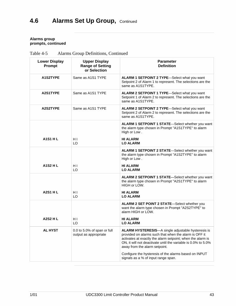
1/01 UDC3300 Limit Controller Product Manual 43
4.6 Alarms Set Up Group, Continued
Alarms groupprompts, continued
Table 4-5 Alarms Group Definitions, Continued
Lower DisplayPrompt
Upper DisplayRange of Setting
or Selection
ParameterDefinition
A1S2TYPE Same as A1S1 TYPE ALARM 1 SETPOINT 2 TYPE—Select what you wantSetpoint 2 of Alarm 1 to represent. The selections are thesame as A1S1TYPE.
A2S1TYPE Same as A1S1 TYPE ALARM 2 SETPOINT 1 TYPE—Select what you wantSetpoint 1 of Alarm 2 to represent. The selections are thesame as A1S1TYPE.
A2S2TYPE Same as A1S1 TYPE ALARM 2 SETPOINT 2 TYPE—Select what you wantSetpoint 2 of Alarm 2 to represent. The selections are thesame as A1S1TYPE.
A1S1 H L H ILO
ALARM 1 SETPOINT 1 STATE—Select whether you wantthe alarm type chosen in Prompt "A1S1TYPE" to alarmHigh or Low .
HI ALARMLO ALARM
A1S2 H L H ILO
ALARM 1 SETPOINT 2 STATE—Select whether you wantthe alarm type chosen in Prompt "A1S2TYPE" to alarmHigh or Low .
HI ALARMLO ALARM
A2S1 H L H ILO
ALARM 2 SETPOINT 1 STATE—Select whether you wantthe alarm type chosen in Prompt "A2S1TYPE" to alarmHIGH or LOW.
HI ALARMLO ALARM
A2S2 H L H ILO
ALARM 2 SET POINT 2 STATE—Select whether youwant the alarm type chosen in Prompt "A2S2TYPE" toalarm HIGH or LOW.
HI ALARMLO ALARM
AL HYST 0.0 to 5.0% of span or fulloutput as appropriate
ALARM HYSTERESIS—A single adjustable hysteresis isprovided on alarms such that when the alarm is OFF itactivates at exactly the alarm setpoint; when the alarm isON, it will not deactivate until the variable is 0.0% to 5.0%away from the alarm setpoint.
Configure the hysteresis of the alarms based on INPUTsignals as a % of input range span.

44 UDC3300 Limit Controller Product Manual 1/01
4.7 Calibration Data
Introduction The prompts used here are for field calibration purposes. Refer to Section6 – Calibration in this manual for complete information.
4.8 Status Test Data
Introduction The prompts used here are for determining the reason for a controllerfailure. Refer to the Section 7 – Troubleshooting in this manual forcomplete information.

1/01 UDC3300 Limit Controller Product Manual 45
Section 5 – Operation
5.1 Overview
Introduction This section gives you all the information necessary to monitor andoperate your controller. Review the Operator Interface shown in“Monitoring” to make sure you are familiar with the indicator definitions.The key functions are listed in Section 1 — Overview.
What’s in thissection?
This section contains the following topics:
Topic See Page
5.1 Overview 45
5.2 How to Power Up the ControllerDiagnostic TestsTroubleshootingDisplay and Key Check
46464647
5.3 Enter a Security CodeProcedure
4848
5.4 How to Operate Your Limit ControllerOperating PrinciplesSetting a Display ModeViewing Limit Action Duration or Peak PV ValueSelecting a Setpoint ValueHigh or Low Limit IndicationNon-Latching Relay Alarm ConditionsDigital Input OptionHow to Reset the Latching Relay
495050505051515151
5.5 How to Monitor Your Limit ControllerDiagnostic Error MessagesRS422 CommunicationsDMCS Communications
52525353
5.6 Alarm SetpointsIntroductionDisplaying or Changing the Alarm Setpoints
545454
5.7 Restarting After a Power Loss 55

46 UDC3300 Limit Controller Product Manual 1/01
5.2 How to Power Up the Controller
Apply power When power is applied, the controller will run three diagnostic tests. Allthe displays will light and then the controller will go into automatic mode.
Diagnostic tests Table 5-1 lists the three diagnostic tests.
Table 5-1 Power Up Diagnostic Tests
Prompt on Lower Display Condition
RAM TEST Check RAM
CONFTEST Check Non-volatile memory
CAL TEST Check Calibration
Test failures If one or more of these tests fail, the controller will go to the FailsafeMode, and “FAILSAFE” will flash in the lower display.
Troubleshooting Refer to “STATUS TESTS” in Section 7 — Troubleshooting to identifyand correct the problem.
Continued on next page

1/01 UDC3300 Limit Controller Product Manual 47
5.2 How to Power Up the Controller, Continued
Check the displaysand keys
Use the procedure in Table 5-2 to run the display and key test.
Table 5-2 Procedure for Testing the Displays and Keys
Press Result
SET UP
and hold in,then
FUNCTION
at the same time
The controller will run a display test. All the displays willlight for 8 seconds, then the displays will look like this:
try all
Lower Display
keys
Upper Display
Press each key to see if itworks
When the key is pressed, the lower display will indicate thename of the key pressed.
Key Pressed Lower DisplayFUNCTION FUNCTION
LOWER DISPLAY LWR DISP
SET UP SET UP
INCRMENT
DECRMENT
RESET RESET
+ INCRDECR
FUNCTION+SETUP FUNC SU
UPPER BLANK KEY UNUSED
LOWER BLANK KEY RESTORE
If no key is pressed for 20 seconds, the test will time out and the controllerwill go into control mode.
If any test fails, go to “Controller Failure Symptoms” in Section 7 —Troubleshooting.
Key error When a key is pressed and the prompt “KEY ERROR” appears in thelower display, it will be for one of the following reasons:
• parameter not available,
• not in Set Up mode, press [SET UP] key first,
• key malfunction, do keyboard test.

48 UDC3300 Limit Controller Product Manual 1/01
5.3 Enter a Security Code
Introduction The LOCKOUT feature in the UDC3300 is used to inhibit changes (viakeyboard) of certain functions or parameters by unauthorized personnel.There are different levels of LOCKOUT depending on the level ofsecurity required. These levels are:
NONECALIB+CONFMAX
See Section 4 — Configuration Definitions for details.
Security codenumbers
The level of keyboard lockout may be changed in the Set Up mode.However, knowledge of a security code number (1 to 4095) may berequired to change from one level of lockout to another.
When a controller leaves the factory, it has a security code of 0 whichpermits changing from one lockout level to another without entering anyother code number.
Procedure If you require the use of a security code, select a number from 1 to 4095and enter it when the lockout level is configured as “NONE”.Thereafter, that selected number must be used to change the lockout levelfrom something other than “NONE”.
CAUTION Write the number on the Configuration Record Sheet in theconfiguration section so you will have a permanent record; or, in case of aproblem, refer to the keyboard failure troubleshooting section.
Use the procedure in Table 5-3 to enter a security code.
Table 5-3 Procedure for Entering a Security Code
Step Press Action
1
SET UP
Until you see
LOCKOUT
Lower Display
SET UP
Upper Display
2
FUNCTION
Until you see
SECURITY
Lower Display
0
Upper Display
3or
to enter a four digit number in the upper display(1 to 4095)
This will be your security code.

1/01 UDC3300 Limit Controller Product Manual 49
5.4 How to Operate Your Limit Controller
Overview The indicators and displays on the operator interface let you see what ishappening to your process and how the controller is responding.
Figure 5-1 is a view of the operator interface. A description of the displaysand indicators is included.
Figure 5-1 Operator Interface
Upper Display - Six Characters • Normal Operation - four digits dedicated to display the process variable, or blank • Configuration Mode - displays parameter value or selection
Lower Display - Eight characters • Normal Operation - displays the value of limit control setpoint, or indicates "LIMIT OK". When alarm condition exists, it alternates between the setpoint value and the word "LIMIT". • Configuration Mode - displays function group and parameters
ALM
DI
RSP
OUT
1
1
1 2 F C
FUNCTION
SET UP
LOWER DISPLAY
Indicator definition when lit
ALM - Alarm conditions exist
DI - Digital Input active
F - °Fahrenheit being used
C - °Centigrade being used
Keys - See Table 1-1
RESET
22642
Decimal point position In each display, when no decimal place is configured, the right-mostcharacter is blank.
When a single decimal position has been configured and values greaterthan 1000 are displayed, the right-most character is blank but the decimalpoint will be lit.
Continued on next page
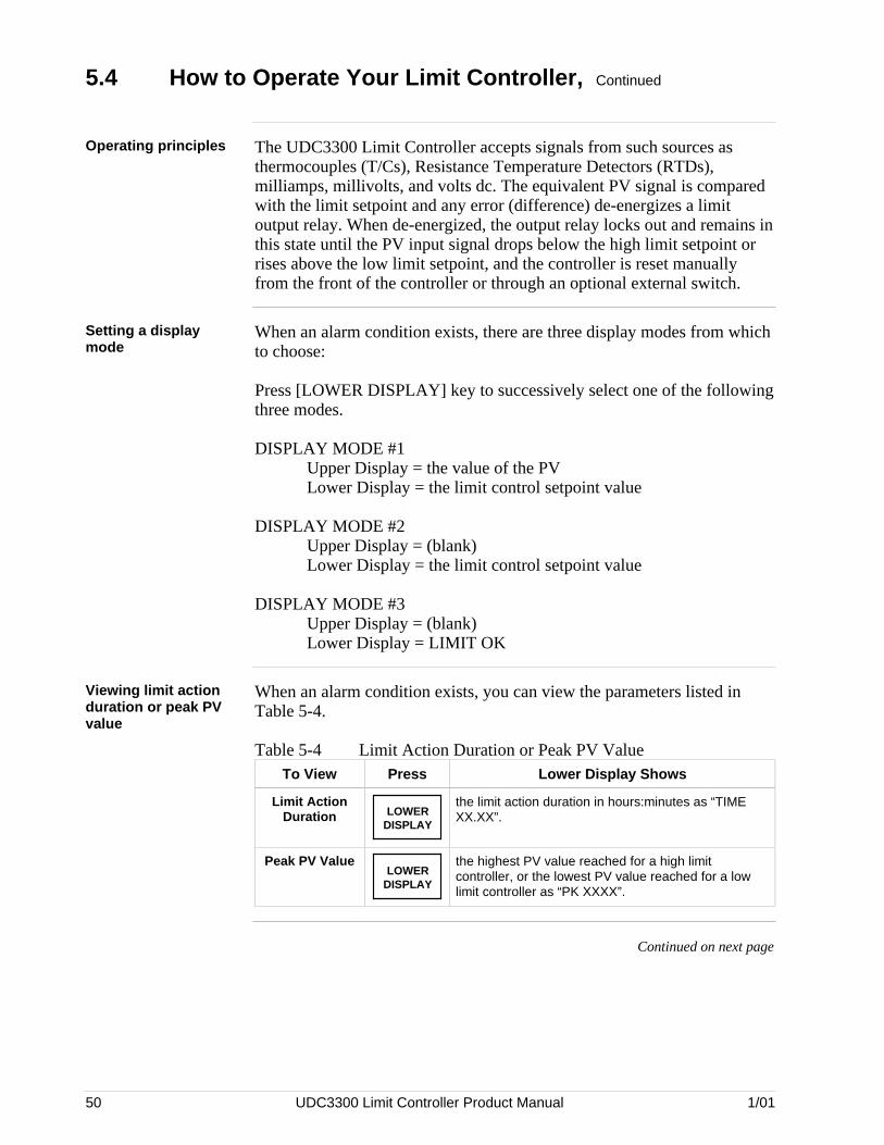
50 UDC3300 Limit Controller Product Manual 1/01
5.4 How to Operate Your Limit Controller, Continued
Operating principles The UDC3300 Limit Controller accepts signals from such sources asthermocouples (T/Cs), Resistance Temperature Detectors (RTDs),milliamps, millivolts, and volts dc. The equivalent PV signal is comparedwith the limit setpoint and any error (difference) de-energizes a limitoutput relay. When de-energized, the output relay locks out and remains inthis state until the PV input signal drops below the high limit setpoint orrises above the low limit setpoint, and the controller is reset manuallyfrom the front of the controller or through an optional external switch.
Setting a displaymode
When an alarm condition exists, there are three display modes from whichto choose:
Press [LOWER DISPLAY] key to successively select one of the followingthree modes.
DISPLAY MODE #1Upper Display = the value of the PVLower Display = the limit control setpoint value
DISPLAY MODE #2Upper Display = (blank)Lower Display = the limit control setpoint value
DISPLAY MODE #3Upper Display = (blank)Lower Display = LIMIT OK
Viewing limit actionduration or peak PVvalue
When an alarm condition exists, you can view the parameters listed inTable 5-4.
Table 5-4 Limit Action Duration or Peak PV ValueTo View Press Lower Display Shows
Limit ActionDuration LOWER
DISPLAY
the limit action duration in hours:minutes as “TIMEXX.XX”.
Peak PV ValueLOWER
DISPLAY
the highest PV value reached for a high limitcontroller, or the lowest PV value reached for a lowlimit controller as “PK XXXX”.
Continued on next page

1/01 UDC3300 Limit Controller Product Manual 51
5.4 How to Operate Your Limit Controller, Continued
Selecting a setpointvalue
Use the procedure in Table 5-5 to change the setpoint value in the lowerdisplay.
Table 5-5 Change a Setpoint Value Procedure
Step Press Action
1LOWER
DISPLAY
until you have selected display mode #1 or #2.
2
or
This changes the value of the limit controller setpoint.
NOTE: To change setpoint values quickly, you can adjusta more significant digit in the lower display by holding inone key [s] or [t] and pressing the other [s] or [t] at thesame time. The adjustment will move one digit to the left.Press the key again and you will move another digit to theleft.
High or low limitindication
When the High or Low limit setpoint is exceeded the lower displayalternately indicates “the limit control setpoint value” and the word“LIMIT.” This will continue until you reset the latching relay.
Non-latching relayalarm conditions
The alarm is active if alarm setpoint 1 or alarm setpoint 2 is exceeded. Thealarm goes inactive when the value goes into the allowed region by morethan the hysteresis.
Digital input option The digital input option detects the state of external contacts. On contactclosure, the limit controller will be reset if the option has been enabled atprompt “EXT RSET” in Set Up group “Limit.” (See Sections 3 and 4 forexplanation.)
How to reset thelatching relay
The latching relay cannot be reset until the PV input signal drops belowthe high limit setpoint or rises above the low limit setpoint.
Press the [RESET] key or make contact closure of an external switch if thedigital input option is present.
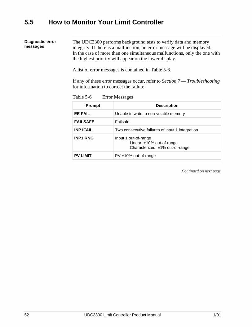
52 UDC3300 Limit Controller Product Manual 1/01
5.5 How to Monitor Your Limit Controller
Diagnostic errormessages
The UDC3300 performs background tests to verify data and memoryintegrity. If there is a malfunction, an error message will be displayed.In the case of more than one simultaneous malfunctions, only the one withthe highest priority will appear on the lower display.
A list of error messages is contained in Table 5-6.
If any of these error messages occur, refer to Section 7 — Troubleshootingfor information to correct the failure.
Table 5-6 Error Messages
Prompt Description
EE FAIL Unable to write to non-volatile memory
FAILSAFE Failsafe
INP1FAIL Two consecutive failures of input 1 integration
INP1 RNG Input 1 out-of-rangeLinear: ±10% out-of-rangeCharacterized: ±1% out-of-range
PV LIMIT PV ±10% out-of-range
Continued on next page

1/01 UDC3300 Limit Controller Product Manual 53
5.5 How to Monitor Your Limit Controller, Continued
RS422communications
Refer to the separate manual shipped with this controller.
DMCScommunications (alsorefer to Gatewaymanual — Section 10)
Changing Parameters from the KeyboardThe following occurs when parameters are changed from the keyboard:
LOCAL SETPOINTWhen the local setpoint is changed, its new value will be entered into non-volatile memory as soon as another key is pressed (other than raise/lower).If no other key is pressed, the new setpoint is automatically entered intonon-volatile memory ONE-HALF MINUTE following the last change.Obviously, if someone turns power off a unit within one-half minutefollowing a setpoint change and during which there was no furtherkeyboard activity, the new setpoint will not be remembered when power isrestored.
OTHER THAN SETPOINTWhen any parameter, other than setpoint, is changed, its new value will beentered into non-volatile memory as soon as another key (other thanraise/lower) is pressed. If no other key is pressed, the new parameter isautomatically entered into non-volatile memory at one minute followingthe last change. Obviously, if someone turns the power off a unit withinone minute following a parameter change (other than setpoint) and duringwhich there was no further keyboard activity, the new parameter valuewill not be remembered when power is restored.
MONITORING DMCS COMMUNICATIONSWhen a Limit Controller (non-FM models only) goes into “slave” mode,the LED indicator for RSP goes “ON” indicating “SLAVE” mode. Also,the keys do not work. You cannot make any adjustments to theconfigurable parameters.

54 UDC3300 Limit Controller Product Manual 1/01
5.6 Alarm Setpoints
Introduction An alarm consists of a relay contact and an operator interface indication.The alarm is de-energized if Setpoint 1 or Setpoint 2 is exceeded. Thealarm is energized when the monitored value goes into the allowed regionby more than the hysteresis.
The relay contacts can be wired for normally open (NO) or normallyclosed (NC) at the rear terminals. See Section 2 — Installation for details.
There are four alarm setpoints, two for each alarm. The type and state(High or Low) is selected during configuration. See Section 3 —Configuration for details.
Procedure fordisplaying andchanging the alarmsetpoints
The procedure for displaying and changing the alarm setpoints is listed inTable 5-7.
Table 5-7 Procedure for Displaying or Changing the Alarm Setpoints
Step Operation Press Action
1 Access theAlarm Set Upgroup
SET UPUntil you see:
ALARMS
Lower Display
SET UP
Upper Display
2 Access theAlarm SetpointValues
FUNCTIONuntil you see the desired alarm setpoint andits value. The specific prompts are shownbelow.
Lower Display
Upper DisplayThe alarm setpoint value
A1S1 VAL = (Alarm 1, Setpoint 1 value)
A1S2 VAL = (Alarm 1, Setpoint 2 value)
A2S1 VAL = (Alarm 2, Setpoint 1 value)
A2S2 VAL = (Alarm 2, Setpoint 2 value)
or
to change any alarm setpoint value youselect in the upper display.
3 Return to normaloperation LOWER
DISPLAY

1/01 UDC3300 Limit Controller Product Manual 55
5.7 Restarting After Power Loss
Power-up logic Configurable power-up logic lets you select the latching output relay torequire “reset” or to provide normal operation at power-up.
If the power to the controller fails and power is reapplied, the controllergoes through power-up tests then starts in one of the followingconfigurable conditions:
Display indications If you have configured:UPPER DISPLAY = RESETLOWER DISPLAY = POWER UP
The lower display will alternately blink the limit setpoint value andthe word “LIMIT.” This will require reset via the [RESET] key orexternal switch to obtain normal operation.
If you have configured:UPPER DISPLAY = NORMALLOWER DISPLAY = POWER UP
The displays and controller will function normally; i.e., no reset oflatching relay is required unless a limit has been exceeded. If thelimit was latched when power went down, the unit will be in limit atpower-up.
Refer to the Configuration section under Set Up prompt “LIMIT” andmake your selection at Function prompt “POWER UP.”

56 UDC3300 Limit Controller Product Manual 1/01
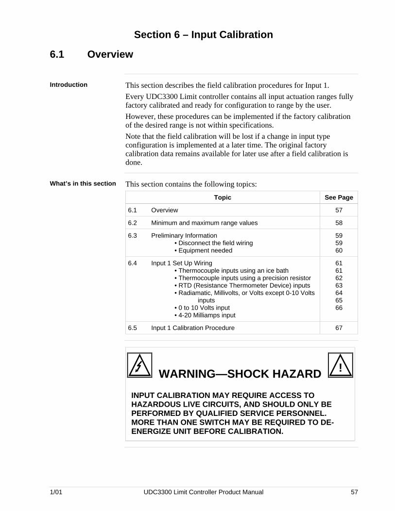
1/01 UDC3300 Limit Controller Product Manual 57
Section 6 – Input Calibration
6.1 Overview
Introduction This section describes the field calibration procedures for Input 1.
Every UDC3300 Limit controller contains all input actuation ranges fullyfactory calibrated and ready for configuration to range by the user.
However, these procedures can be implemented if the factory calibrationof the desired range is not within specifications.
Note that the field calibration will be lost if a change in input typeconfiguration is implemented at a later time. The original factorycalibration data remains available for later use after a field calibration isdone.
What’s in this section This section contains the following topics:
Topic See Page
6.1 Overview 57
6.2 Minimum and maximum range values 58
6.3 Preliminary Information• Disconnect the field wiring• Equipment needed
595960
6.4 Input 1 Set Up Wiring• Thermocouple inputs using an ice bath• Thermocouple inputs using a precision resistor• RTD (Resistance Thermometer Device) inputs• Radiamatic, Millivolts, or Volts except 0-10 Volts
inputs• 0 to 10 Volts input• 4-20 Milliamps input
61616263646566
6.5 Input 1 Calibration Procedure 67
WARNING—SHOCK HAZARD !
INPUT CALIBRATION MAY REQUIRE ACCESS TOHAZARDOUS LIVE CIRCUITS, AND SHOULD ONLY BEPERFORMED BY QUALIFIED SERVICE PERSONNEL.MORE THAN ONE SWITCH MAY BE REQUIRED TO DE-ENERGIZE UNIT BEFORE CALIBRATION.

58 UDC3300 Limit Controller Product Manual 1/01
6.2 Minimum and Maximum Range Values
Select the rangevalues
You should calibrate the controller for the minimum (0%) and maximum(100%) range values of your particular sensor.
Select the Voltage or Resistance equivalent for 0% and 100% range valuesfrom Table 6-1. Use these values when calibrating your controller.
Table 6-1 Voltage and Resistance Equivalents for 0% and 100% Range Values
Sensor Type PV Input Range Range Values
° F ° C 0% 100%
ThermocouplesB 0 to 3300 –18 to 1816 –0.100 mV 13.769 mV
E -454 to 1832 –270 to 1000 –9.835 mV 76.373 mV
E (low) -200 to 1100 –129 to 593 –6.472 mV 44.455 mV
J 0 to 1600 –18 to 871 –0.886 mV 50.060 mV
J (low) 20 to 770 –7 to 410 –0.334 mV 22.400 mV
K 0 to 2400 –18 to 1816 –0.692 mV 52.952 mV
K (low) –20 to 1000 –29 to 538 –1.114 mV 22.255 mV
NiNiMoly (NNM68) 32 to 2500 0 to 1371 0.000 mV 71.330 mV
NiNiMoly (low) 32 to 1260 0 to 682 0.000 mV 31.820 mV
NiMo-NiCo (NM90) 32 to 2500 0 to 1371 0.000 mV 71.773 mV
NiMo-NiCo (low) 32 to 1260 0 to 682 0.000 mV 31.825 mV
Nicrosil Nisil (Nic) 0 to 2372 –18 to 1300 –0.461 mV 47.513 mV
R 0 to 3100 –18 to 1704 –0.090 mV 20.281 mV
S 0 to 3100 –18 to 1704 –0.092 mV 17.998 mV
T -300 to 700 –184 to 371 –5.341 mV 19.097 mV
T (low) -200 to 500 –129 to 260 –4.149 mV 12.574 mV
W5W26 0 to 4200 –18 to 2315 –0.234 mV 37.075 mV
W5W26 (low) 0 to 2240 –18 to 1227 –0.234 mV 22.283 mV
Honeywell RadiamaticType RHType RI
0 to 34000 to 3200
–18 to 1871–18 to 1760
0.00 mV0.00 mV
57.12 mV60.08 mV
RTD(IEC Alpha=0.00385)
100 ohms100 ohms (low)
200 ohms500 ohms
-300 to 1200-300 to 300-300 to 1200-300 to 1200
–184 to 649–184 to 149–184 to 649–184 to 649
25.18 ohms25.18 ohms50.36 ohms
125.90 ohms
274.96 ohms156.90 ohms549.92 ohms
1374.80 ohms
LinearMilliamps 4 to 20 mA*
0 to 20 mA*4.00 mA0.00 mA
20.00 mA20.00 mA
Millivolts 0 to 10 mV*0 to 50 mV*
0.00 mV0.00 mV
10.00 mV50.00 mV
Volts 1 to 5 Volts*0 to 5 Volts*
0 to 10 Volts*
1.00 Volts0.00 Volts0.00 Volts
5.00 Volts5.00 Volts
10.00 Volts
* not available for FM models

1/01 UDC3300 Limit Controller Product Manual 59
6.3 Preliminary Information
Calibration steps Use the following steps when calibrating an input.
Step Action
1 Find the minimum and maximum range values for your PV inputrange from Table 6-1.
2 Disconnect the field wiring and find out what equipment you will needto calibrate. DO NOT remove external resistor assemblies (ifpresent).
3 Wire the calibrating device to your controller according to the Set Upwiring instructions for your particular input.
4 Follow the calibration procedure given for Input #1 after the controllerhas warmed up for a minimum of 15 minutes.
Disconnect the fieldwiring
Tag and disconnect any field wiring connected to the input terminals onthe rear of the controller.
Figure 6-1 shows the wiring terminal designations for Input #1.
Figure 6-1 Input #1 Wiring Terminals
1
2
3
4
5
6
7
8
9
L1
L2/N
22
23
24
25
26
27
10
11
12
13
14
15
16
17
R
+–
Input 1 connections
22648
Continued on next page

60 UDC3300 Limit Controller Product Manual 1/01
6.3 Preliminary Information, Continued
Equipment needed Table 6-2 lists the equipment you will need to calibrate the specific typesof inputs that are listed in the table. You will need a screwdriver toconnect these devices to your controller.
Table 6-2 Equipment Needed
Type of Input Equipment Needed
Thermocouple Inputs(Ice Bath)
• A calibrating device with ±0.02% accuracy for useas a signal source such as a millivolt source.
• Thermocouple extension wire that corresponds withthe type of thermocouple that will be used with thecontroller input.
• Two insulated copper leads for connecting thethermocouple extension wire from the ice baths tothe precision calibrator.
• Two containers of crushed ice.
Thermocouple Inputs(Precision Resistor)
• A calibrating device with ±0.02% accuracy for useas a signal source such as a millivolt source.
• Two insulated copper leads for connecting thecalibrator to the controller.
• A precision 500 ohm resistor ±0.1% connectedacross input #1 terminals 25 (R) and 27 (–).
RTD (Resistance ThermometerDevice)
• A decade box, with ±0.02% accuracy, capable ofproviding stepped resistance values over aminimum range of 0 to 1400 ohms with a resolutionof 0.1 ohm.
• Three insulated copper leads for connecting thedecade box to the controller.
Milliampere, Millivolt, Volts, andRadiamatic
• A calibrating device with ±0.02% accuracy for useas a signal source.
• Two insulated copper leads for connecting thecalibrator to the controller.
• Place current source at zero before switching ON.
• Do not switch current sources OFF/ON whileconnected to the UDC3300 input.

1/01 UDC3300 Limit Controller Product Manual 61
6.4 Input #1 Set Up Wiring
Thermocouple inputsusing an ice bath
Refer to Figure 6-2 and wire the controller according to the proceduregiven in Table 6-3.
Table 6-3 Set Up Wiring Procedure for Thermocouple Inputs Using An Ice Bath
Step Action
1 Connect the copper leads to the calibrator.
2 Connect a length of thermocouple extension wire to the end of each copperlead and insert the junction points into the ice bath.
3 Connect the thermocouple extension wires to the terminals for Input #1. SeeFigure 6-2.
4 Connect a cold junction resistor to terminals 25 and 27 for Input #1. SeeFigure 6-2.
Figure 6-2 Wiring Connections for Thermocouple Inputs Using an Ice Bath
1
2
3
4
5
6
7
8
9
10
11
12
13
14
15
16
17
L1
L2/N
22
23
24
25
26
27
+–
Ice Bath
Millivolt Source
T/C Extension Wire
Copper Leads
+–
24205
C/J Resistor
Continued on next page

62 UDC3300 Limit Controller Product Manual 1/01
6.4 Input #1 Set Up Wiring, Continued
Thermocouple inputsusing a precisionresistor
Refer to Figure 6-3 and wire the controller according to the proceduregiven in Table 6-4.
Table 6-4 Set Up Wiring Procedure for Thermocouple Inputs Using a Precision Resistor
Step Action
1 Connect the copper leads to the calibrator.
2 Disconnect the cold junction resistor.
3 Install a 500-ohm precision resistor across terminal 25 (R) and terminal27 (–). See Figure 6-3.
4 Subtract the millivolt value for 77°F (25°C) from the zero and span value foryour range (see Table 6-1 for zero and span values) and use the adjustedvalue when calibrating.
Figure 6-3 Wiring Connections for Thermocouple Inputs Using a Precision Resistor
1
2
3
4
5
6
7
8
9
10
11
12
13
14
15
16
17
L1
L2/N
22
23
24
25
26
27
+–
Precision 500 Ohm ResistorCopper Leads
Millivolt Source+
–
R
1
1 Caution: The accuracy of the controller is directly affected by the accuracy of this resistor. At a minimum, use a 0.1%, 25ppm resistor.
22628
Continued on next page

1/01 UDC3300 Limit Controller Product Manual 63
6.4 Input #1 Set Up Wiring, Continued
RTD inputs Use the copper leads and connect the calibrator to the rear terminals ofInput #1. See Figure 6-4.
Figure 6-4 Wiring Connections for RTD (Resistance Thermometer Device)
1
2
3
4
5
6
7
8
9
10
11
12
13
14
15
16
17
L1
L2/N
22
23
24
25
26
27
R
+–
Decade Resistance
Box
Copper Leads equal length 22629
Continued on next page

64 UDC3300 Limit Controller Product Manual 1/01
6.4 Input #1 Set Up Wiring, Continued
Radiamatic, millivolts,or volts (except 0 to10 volts) inputs
Use the copper leads and connect the calibrator to the rear terminals ofInput #1. See Figure 6-5.
Figure 6-5 Wiring Connections for Radiamatic, Millivolts, or Volts (except 0 to 10 Volts)
+
1
2
3
4
5
6
7
8
9
10
11
12
13
14
15
16
17
L1
L2/N
22
23
24
25
26
27–
Millivolt/Volt Source
Copper Leads
+–
22630
Continued on next page

1/01 UDC3300 Limit Controller Product Manual 65
6.4 Input #1 Set Up Wiring, Continued
0 to 10 volt inputs Use the copper leads and connect the calibrator to the rear terminals ofInput #1. See Figure 6-6.
Figure 6-6 Wiring Connections for 0 to 10 Volt Inputs
1
2
3
4
5
6
7
8
9
10
11
12
13
14
15
16
17
L1
L2/N
22
23
24
25
26
27
0 to 10 Volt
SourceCopper Leads
+
–
100K
100K
22631
Continued on next page

66 UDC3300 Limit Controller Product Manual 1/01
6.4 Input #1 Set Up Wiring, Continued
4 to 20 mA inputs Use the copper leads and connect the calibrator to the rear terminals ofInput #1. See Figure 6-7.
Figure 6-7 Wiring Connections for 4 to 20 mA Inputs
+
1
2
3
4
5
6
7
8
9
10
11
12
13
14
15
16
17
L1
L2/N
22
23
24
25
26
27–
4 to 20 mA Source
Copper Leads
+–
250Ωresistor assy
22632

1/01 UDC3300 Limit Controller Product Manual 67
6.5 Input #1 Calibration Procedure
Introduction Apply power and allow the controller to warm up for 15 minutes beforeyou calibrate. Read “Set Up Wiring” before beginning the procedure.Make sure you have “LOCKOUT” set to “NONE.” See Section 3 –Configuration.
CAUTION For linear inputs, avoid step changes in inputs. Vary smoothlyfrom initial value to final 100% value.
Procedure The Calibration procedure for Input #1 is listed in Table 6-5.
Table 6-5 Input #1 Calibration Procedure
Step Description Press Action
1 Enter Calibration Mode
SET UP
until you seeINPUT 1
Lower Display
CALIB
Upper Display
FUNCTION
You will see:
CAL IN1
Lower Display
DISABL
Upper Display
The calibration sequence is enabled and you will see:
CAL IN1
Lower Display
BEGIN
Upper Display
At the completion of the sequence, the selectionautomatically reverts to disable.
2 Calibrate 0%
FUNCTION
You will see:
IN1 ZERO
Lower Display
APPLY
Upper Display
Adjust your calibration device to an output signal equal tothe 0% range value for your particular input sensor. SeeTable 6-1 for Voltage or Resistance equivalents.Wait 15 seconds, then go to the next step.
Continued on next page

68 UDC3300 Limit Controller Product Manual 1/01
6.5 Input #1 Calibration Procedure, Continued
Procedure, continued
Table 6-5 Input #1 Calibration Procedure, Continued
Step Description Press Action
3 Calibrate 100%
FUNCTION
You will see:
IN1 SPAN
Lower Display
APPLY
Upper Display
Adjust your calibration device to an output signal equal tothe 100% range value for your particular input sensor. SeeTable 6-1 for Voltage or Resistance equivalents.Wait 15 seconds, and
If… Then…you are calibrating a Go to step 4Thermocouple input
you are calibrating other Go to step 5than a Thermocouple input
4 Check the Cold JunctionTemperature
ATTENTIONThe accuracy of thecontroller is directlyaffected by the accuracy ofthis value. Change thisvalue only if the zero andspan calibrationprocedures did not bringthe controller within thespecified accuracyrequirements.
FUNCTION
The calculations for zero and span are now stored andyou will see:
Lower Display
Upper Display
C-J TEMP
The cold junction temperature at the rear terminals
The value in the upper display is in the tenths of a degree.It is the current reading of the temperature as measured atthe thermocouple terminals and recognized by thecontroller. You can change this value, if it is in error, usingthe s or t key.
ATTENTION When calibrating T/C inputs using aprecision resistor, calibrate the cold junction as77°F(25°C).
5 Exit the Calibration Mode
FUNCTION
The controller will store the calibration constants and exitcalibration mode.

1/01 UDC3300 Limit Controller Product Manual 69
Section 7 – Troubleshooting / Service
7.1 Overview
Introduction Instrument performance can be adversely affected by installation andapplication problems as well as hardware problems. We recommend thatyou investigate the problems in the following order:
• Installation related problems• Application related problems• Hardware and software related problems
and use the information presented in this section to solve them.
If a replacement of any part is required, follow the procedures listed under“Replacement Procedures”.
WARNING—SHOCK HAZARD !
INPUT CALIBRATION MAY REQUIRE ACCESS TOHAZARDOUS LIVE CIRCUITS, AND SHOULD ONLY BEPERFORMED BY QUALIFIED SERVICE PERSONNEL.MORE THAN ONE SWITCH MAY BE REQUIRED TO DE-ENERGIZE UNIT BEFORE CALIBRATION.
What’s in thissection?
The following topics are covered in this section.
Topic See Page
7.1 Overview 69
7.2 Troubleshooting Aids 71
7.3 Power-up Tests 73
7.4 Status Tests 74
7.5 Background Tests 76
7.6 Controller Failure Symptoms 78
7.7 Troubleshooting Procedures 79
7.8 Parts Replacement Procedures 83
7.9 Maintenance (Cleaning) 92
Continued on next page

70 UDC3300 Limit Controller Product Manual 1/01
7.1 Overview, Continued
Installation relatedproblems
Read the Installation section in this manual to make sure the UDC3300has been properly installed. The installation section provides informationon protection against electrical noise, connecting external equipment tothe controller, and shielding and routing external wiring.
ATTENTION System noise induced into the controller will result indiagnostic error messages recurring. If the diagnostic error messages canbe cleared, it indicates a “soft” failure and is probably noise related.
If system noise is suspected, completely isolate the controller from allfield wiring. Use calibration sources to simulate PV and check allcontroller functions; i.e. Inputs, Alarms, etc.
Application relatedproblems
Review the application of the controller; then, if necessary, direct yourquestions to the local sales office.
Hardware andsoftware relatedproblems
Use the troubleshooting error message prompts and controller failuresymptoms to identify typical failures which may occur in the controller.Follow the troubleshooting procedures to correct them.

1/01 UDC3300 Limit Controller Product Manual 71
7.2 Troubleshooting Aids
Overall errormessages
An error message can occur• at power-up• during continuous background tests while in normal operation• when the Status Tests are requested
Table 7-1 lists all the error message prompts that you could see, the reasonfor the failure, and under what test group the prompt could appear.
Refer to Tables 7-3 (Power-up), 7-5 (Status), and 7-6 (Background) for theparticular test group indicated.
Table 7-1 Error Message Prompts
ErrorMessage
(lowerdisplay)
Reason for Failure Test Group Refer toTable
CAL TEST Calibration test failure Power-up orStatus
7-37-5
CONFTEST Configuration test failure Power-up orStatus
7-37-5
E E FAIL Unable to write to non-volatilememory
Background 7-6
FACT CRC Factory Calibration CyclicRedundancy test
Status 7-5
FAILSAFE Controller in Failsafe Power-up,Background, orStatus
7-37-57-6
INP1FAIL Two consecutive failures ofInput 1 integration
Background 7-6
INP1 RNG Input 1 Out of Range Background 7-6
PV LIMIT PV Out of Range Background 7-6
RAM TEST RAM test failed Power-up orStatus
7-37-5
Continued on next page

72 UDC3300 Limit Controller Product Manual 1/01
7.2 Troubleshooting Aids, Continued
Controller failuresymptoms
Other failures may occur that deal with the Power, Latching Output Relay,or Non-Latching Alarm Relays. Refer to the controller failure symptom inTable 7-7 to determine what is wrong and the troubleshooting proceduresto use to correct the problem.
Check Installation If a set of symptoms still persists, refer to Section 2 — Installation andensure proper installation and proper use of the controller in the system.
Determining thesoftware version
Table 7-2 lists the procedure for identifying the software version number.
Table 7-2 Procedure for Identifying the Software Version
Step Operation Press Action
1 SelectSTATUSSet Up Group
SET UPUntil you see:
STATUS
Lower Display
READ
Upper Display
2 Read thesoftware version FUNCTION
Until you see:
Lower Display
Upper Display
VERSION
Software version Number
Please give this number to the CustomerSupport person. It will indicate which versionof UDC3300 you have and help themdetermine a solution to your problem.

1/01 UDC3300 Limit Controller Product Manual 73
7.3 Power-up Tests
What happens atpower-up
When the controller is powered-up, three tests are run by the UDC3300software to ensure memory integrity.
As the tests are run, the displays will appear as shown in Table 7-3.
Table 7-3 Power-up Tests
Lower Display Upper Display
RAM TEST PASS or FAIL
CONFTEST PASS or FAIL
CAL TEST PASS or FAIL
Test failures If any of these three tests fail, “FAILED” will appear momentarily in theupper display, then a display test is run, after which the controller will gointo manual mode and you will see:
Lower Display
Upper Display
FAILSAFE
PV value
(blinking)
Refer to “Status Tests” to determine which tests have failed and how tocorrect them.

74 UDC3300 Limit Controller Product Manual 1/01
7.4 Status Tests
Introduction When required, the results of these tests can be checked to determine thereason the controller has gone to “Failsafe”.
How to check thestatus tests
The procedure in Table 7-4 tells you how to display the results of thestatus tests. Table 7-5 lists the tests, the reason for the failure, and how tocorrect the problem.
Table 7-4 Procedure for Displaying the Status Tests Results
Step Operation Press Action
1 SelectSTATUSSet Up Group
SET UPUntil you see:
STATUS
Lower Display
READ
Upper Display
2 Read the statustests results FUNCTION
Until you see:
Lower Display
Upper Display
FAILSAFE
NO or YES YES indicates a failure
Successive presses of the [FUNCTION] keywill display the results of the status tests inthe following order:
RAM TESTCONF TESTCAL TESTFACT CRC
Identify the problem and correct the failureas shown in Table 7-5.
Continued on next page

1/01 UDC3300 Limit Controller Product Manual 75
7.4 Status Tests, Continued
Status Tests Table 7-5 lists the Status tests, the reason for their failure, and how tocorrect the failure.
Table 7-5 Status Tests
Test(Lower
Display)
Definition UpperDisplay
Reason for Failure How to Correct the Failure
FAILSAFE Failsafe Fault NO No Failure
YES Burnout configured for noneand input fails.–RAM TEST failed–CONFTEST failed–CALTEST failed
1. Step through the rest of the STATUScheck to identify the particular failure.
Also see Table 7-6, Background tests.
RAM TEST RAM Test Runat
PASS No Failure RAM test passed.
Power-upFAIL RAM Failure 1. Power cycle to see if the error clears.
CONF Configuration PASS No Failure Configuration checksum passed.
TEST ChecksumFAIL Configuration data is in
error.1. Step through STATUS tests – the
controller will recalculate thechecksum.
2. Check all configuration prompts foraccuracy. See Section 3 -Configuration.
CAL TEST Working PASS No Failure Working calibration checksum passed.
CalibrationFAIL The working calibration
constants in the controllerare in error.
1. If the controller has not been fieldcalibrated, see Section 3 -Configuration and change the input toa different type. Enter it, loop throughthe status tests, then return the inputtype to the original one.
2. If the controller has been fieldcalibrated, recalibrate the controller.
FACT CRC FactoryCalibration Test
PASS No Failure Factory calibration cyclic redundancy testpassed.
FAIL Factory set input constantshave been changed due tothe change in input type.
1. Cycle through Status to clear the error.
2. Check the calibration. Make sure 0 and100% are correct values.
3. Recalibrate if step 1 is unsatisfactory.Refer to Section 6 - Input Calibration.

76 UDC3300 Limit Controller Product Manual 1/01
7.5 Background Tests
Introduction The UDC3300 performs on-going background tests to verify data andmemory integrity. If there is a malfunction, an error message will bedisplayed (blinking) in the lower display.
Background tests In the case of more than one simultaneous malfunction, only the one withthe highest priority will appear in the lower display. Table 7-6 lists thesebackground tests, the reason for their failure, and how to correct theproblem.
Table 7-6 Background Tests
LowerDisplay
Reason for Failure How to Correct the Problem
EE FAIL Unable to write to non-volatile memory.Anytime you change a parameter and it isnot accepted, you will see EE FAIL.
1. Check the accuracy of the parameter and re-enter.
2. Try to change something in configuration.
3. Run through STATUS tests to re-write toEEPROM.
FAILSAFE This error message shows whenever thecontroller goes into a failsafe mode ofoperation. This will happen if:
• RAM test failed• Configuration test failed• Calibration test failed• Burnout configured for noneand the input failed.
1. Run through STATUS check to determine thereason for the failure.
2. Press the [SET UP] key until STATUS appears inthe lower display.
3. Press the [FUNCTION] key to see what tests passor fail, then run through the STATUS codes asecond time to see if the error cleared. Correctaccording to the recommendations given in Table7-5.
INP1FAIL Two consecutive failures of input 1integration. i.e., cannot make analog todigital conversion.
1. Make sure the actuation is configured correctly.See Section 3 — Configuration.
2. Make sure the input is correct.
3. Check for gross overranging.
4. Restore the factory calibration:
a. Disconnect the wiring from and place a jumperacross terminals 26 and 27. The controllershould read room temperature if it is configuredfor a thermocouple input.
b. If it does not read room temperature, seeSection 3 – Configuration and change theIN1TYP prompt in the INPUT 1 group toanother type of thermocouple.
c. After the change, press [FUNCTION] key, thenthe [LOWER DISPLAY] key. The limit controllershould read the correct room temperature. If itdoes not, the unit has an input failure.
d. Repeat step b. This time switch the IN1TYPback to the originally selected thermocouple.
e. Repeat step c. The controller is restored withfactory calibration.
f. Remove the jumper and reconnect thethermocouple.
5. Replace the cold junction assembly.
Table continued on next page

1/01 UDC3300 Limit Controller Product Manual 77
7.5 Background Tests, Continued
Background tests,continued
Table 7-6 Background Tests, Continued
LowerDisplay
Reason for Failure How to Correct the Problem
INP1 RNG Input 1 out of range. The process input isoutside the range limits.
If you have a linear input and the rangegoes outside the range limits, thecontroller will switch to Limit mode.
1. Make sure the range and actuation are configuredproperly.
2. Check the input source.
3. Restore the factory calibration:
a. Disconnect the wiring from and place a jumperacross terminals 26 and 27. The controllershould read room temperature if it is configuredfor a thermocouple input.
b. If it does not read room temperature, seeSection 3 – Configuration and change theIN1TYP prompt in the INPUT 1 group toanother type of thermocouple.
c. After the change, press [FUNCTION] key, thenthe [LOWER DISPLAY] key. The limit controllershould read the correct room temperature. If itdoes not, the unit has an input failure.
d. Repeat step b. This time switch the IN1TYPback to the originally selected thermocouple.
e. Repeat step c. The controller is restored withfactory calibration.
f. Remove the jumper and reconnect thethermocouple.
4. Field calibrate. See Section 6 — Input Calibration.
PV LIMIT PV out of range.PV = INP1 + INP1 BIAS
1. Make sure the input signal is correct.
2. Make sure the Bias setting is correct
3. Recheck the calibration. Use Bias of 0.0.

78 UDC3300 Limit Controller Product Manual 1/01
7.6 Controller Failure Symptoms
Introduction In addition to the error message prompts, there are failure symptoms thatcan be identified by noting how the controller displays and indicators arereacting.
Symptoms Compare your symptoms with those shown in Table 7-7 and refer to thetroubleshooting procedure indicated to correct the problem.
Table 7-7 Controller Failure Symptoms
UpperDisplay
LowerDisplay
ControllerOutput
ProbableCause
Trouble-shooting
Procedure
Blank Blank None Power Failure 1
OK Lower Displaydisagrees with
Latching Output Relayfunction
Latching Output Relayfunction disagreeswith Lower Display
Latching Output Relay 2
OK OK External Alarmfunction does notoperate properly
Malfunction in alarm output 3
Display does not function when a key is pressed Keyboard Malfunction 4
Controller fails to go into “Slave” operation during communications Communications Failure 5
Other symptoms If a set of symptoms or prompts other than the one you started withappears while troubleshooting, re-evaluate the symptoms. This may leadto a different troubleshooting procedure.
If the symptom still persists, refer to the installation section in this manualto ensure proper installation and proper use of the controller in yoursystem.

1/01 UDC3300 Limit Controller Product Manual 79
7.7 Troubleshooting Procedures
Introduction The troubleshooting procedures are listed in numerical order as theyappear in Table 7-7. Each procedure lists what to do if you have thatparticular failure and how to do it or where to find the data needed toaccomplish the task.
WARNING—SHOCK HAZARD !
TROUBLESHOOTING MAY REQUIRE ACCESS TOHAZARDOUS LIVE CIRCUITS, AND SHOULD ONLY BEPERFORMED BY QUALIFIED SERVICE PERSONNEL.MORE THAN ONE SWITCH MAY BE REQUIRED TO DE-ENERGIZE UNIT BEFORE SERVICING.
Equipment needed You will need the following equipment in order to troubleshoot thesymptoms listed in the tables that follow:
• DC Milliammeter – mAdc
• Calibration sources – T/c, mV, Volt, etc.
• Voltmeter
Procedure #1 Table 7-8 explains how to troubleshoot power failure symptoms.
Table 7-8 Troubleshooting Power Failure Symptoms
Step What to do How to do it
1 Check the AC line voltage. Use a Voltmeter to measure the ACvoltage across terminals L1 and L2 onthe rear terminal panel of thecontroller.
Check the earth ground connection.
2 Make sure the chassis plugs intothe rear of the case properly.
Withdraw the chassis and visuallyinspect the controller board and theinside of the case.
3 Check the system for Brown-outs,heavy load switching, etc., andconformance to installationinstructions.
Refer to Section 2 - Installation.
Continued on next page

80 UDC3300 Limit Controller Product Manual 1/01
7.7 Troubleshooting Procedures, Continued
Procedure #2 Table 7-9 explains how to troubleshoot Latching Output Relay failuresymptoms.
Table 7-9 Troubleshooting Latching Output Relay Failure
Step What to do How to do it
1 Make sure all the configurable datafor the Limit controller is correct.
See the Configuration section in thismanual to check the configurationdata and to reconfigure, if necessary.
2 Check that the latching relayactuates properly.
Move the setpoint above or below thePV value, depending on the type oflimit control. Listen for the click of therelay as the setpoint moves above orbelow the PV.
Procedure #3 Table 7-10 explains how to troubleshoot Alarm Relay Output failure.
Table 7-10 Troubleshooting Alarm Relay Output Failure
Step What to do How to do it
1 Check the alarm configuration data.If it is correct, check the field wiring.
Reconfigure if necessary.
Refer to Section 3 – Configuration fordetails.
2 Check that the applicable alarmrelay actuates properly dependingon what you have set at prompt“ALARM TYPE”.If it does, check the field wiring.
Place the controller in manual mode.Vary the input to raise and lower thePV around the setpoint. Listen for aclick from the relay as the PV movesin either direction and note that theproper ALM1 or ALM2 is lit.
3 Check the field wiring. Make sure the NO or NC contactwiring is correct on the alarm outputterminals.
Refer to Section 2 – Installation fordetails.
Continued on next page

1/01 UDC3300 Limit Controller Product Manual 81
7.7 Troubleshooting Procedures, Continued
Procedure #4 Table 7-11 explains how to troubleshoot a Keyboard failure.
Table 7-11 Troubleshooting a Keyboard Failure
Step What to do How to do it
1 Make sure the keyboard isconnected properly to theMCU/output and power/inputboards.
Withdraw the chassis from the caseand visually inspect the connection.
2 Controller Keyboard or specific keysmay be “LOCKED OUT” via thesecurity code.
Use your 4 digit security code numberto change the lockout level. Refer toSection 3 – Configuration.
ATTENTION Using “1000” as asecurity code number will override the4-digit code previously entered.
3 Run the keyboard test. Press the [SET UP] key and hold in,then press the [FUNCTION] key at thesame time. The controller will run adisplay test. Then you will see:
TRY ALL
Lower Display
KEYS
Upper Display
Press each key. If it works, the keyname will appear in the lower display.
4 Replace the display/keyboard if anykeys are shorted out.
Refer to “Replacement Procedures” inthis section.
Continued on next page

82 UDC3300 Limit Controller Product Manual 1/01
7.7 Troubleshooting Procedures, Continued
Procedure #5 Table 7-12 explains how to troubleshoot a Communications failure.
Table 7-12 Troubleshooting a Communications Failure
Step What to do How to do it
1 Check the field wiring andtermination resistor.
Refer to the Installation section ofeither the RS422/485 Manual or theGateway Manual depending on theprotocol used.
2 Make sure the CommunicationsPrinted Wiring Board is installedproperly in the controller.
Withdraw the chassis from the caseand inspect the board. See theexploded view (Figure 8-1) for locationof the board. Return the chassis to thecase.
3 Determine if the Communicationsboard is faulty by running a LOCALLOOPBACK TEST.
If the test fails, replace the board.
Run the Local Loopback Test.
Press [SET UP] until you see:
COM
Lower Display
SET UP
Upper Display
Press [FUNCTION] until you see:
LOOPBACK
Lower Display
DISABL
Upper Display
Press s or t, you will see:
LOOPBACK
Lower Display
ENABLE
Upper Display
The test will run until the operatordisables it here.

1/01 UDC3300 Limit Controller Product Manual 83
7.8 Parts Replacement Procedures
Introduction These procedures tell you how to access and replace the following printedwiring boards in your controller.
• Display/Keyboard
• MCU/Output
• Power/Input
• Digital Input
• DMCS Communications
• RS422/485 Communications
Equipment needed To accomplish the procedures that follow, you will need the followingequipment:
• Phillips Head Screwdriver
• Flat Bladed Screwdriver
• Small Pliers
Continued on next page

84 UDC3300 Limit Controller Product Manual 1/01
7.8 Parts Replacement Procedures, Continued
How to remove thechassis
Refer to Figure 7-1 for steps and follow the procedure listed in Table 7-13.
Table 7-13 How to Remove the Chassis
Step Action
1 Loosen the screw on the front face.
2 Insert a flat-bladed screwdriver into the hole on the top of the case as shownin Figure 7-1 and pry chassis forward slightly until the chassis connectorsseparate from the back of the case.
3 Grasp the bezel and pull the chassis out of the case.
Figure 7-1 Chassis Removal
Loosen screw
Insert screwdriver and pry forward
Grasp bezel and pull chassis out
2
3
1
22637
Continued on next page
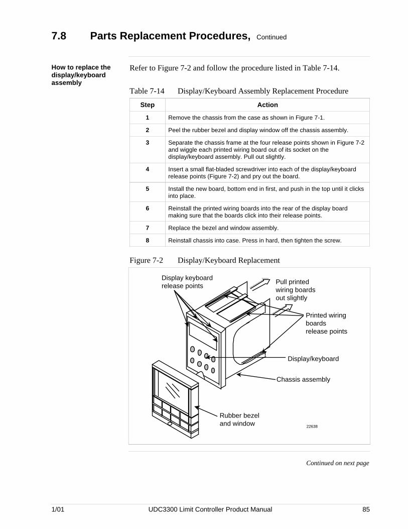
1/01 UDC3300 Limit Controller Product Manual 85
7.8 Parts Replacement Procedures, Continued
How to replace thedisplay/keyboardassembly
Refer to Figure 7-2 and follow the procedure listed in Table 7-14.
Table 7-14 Display/Keyboard Assembly Replacement Procedure
Step Action
1 Remove the chassis from the case as shown in Figure 7-1.
2 Peel the rubber bezel and display window off the chassis assembly.
3 Separate the chassis frame at the four release points shown in Figure 7-2and wiggle each printed wiring board out of its socket on thedisplay/keyboard assembly. Pull out slightly.
4 Insert a small flat-bladed screwdriver into each of the display/keyboardrelease points (Figure 7-2) and pry out the board.
5 Install the new board, bottom end in first, and push in the top until it clicksinto place.
6 Reinstall the printed wiring boards into the rear of the display boardmaking sure that the boards click into their release points.
7 Replace the bezel and window assembly.
8 Reinstall chassis into case. Press in hard, then tighten the screw.
Figure 7-2 Display/Keyboard Replacement
Display keyboard release points
Pull printed wiring boards out slightly
Printed wiring boards release points
Display/keyboard
Chassis assembly
Rubber bezel and window 22638
Continued on next page

86 UDC3300 Limit Controller Product Manual 1/01
7.8 Parts Replacement Procedures, Continued
How to remove theprinted wiring boardsfrom the chassis
To remove the printed wiring boards from the chassis, refer to Figure 7-3and follow the procedure in Table 7-15.
Table 7-15 Printed Wiring Board Removal from Chassis
Step Action
1 Remove the chassis from the case as shown in Figure 7-1.
2 Separate the chassis frame at the release points shown in Figure 7-3 andwiggle each printed wiring board out of its socket on the display/keyboardassembly. Pull both boards out of the chassis assembly.
Figure 7-3 Removing the Printed Wiring Boards
Pull printed wiring boards out of chassis
Printed wiring boards release points
Chassis assembly
Rubber bezel and window
22639
Continued on next page

1/01 UDC3300 Limit Controller Product Manual 87
7.8 Parts Replacement Procedures, Continued
Printed wiring boardidentification
Figure 7-4 identifies each of the printed wiring boards that can bereplaced. Refer to this drawing when following the replacementprocedures for each of the boards, since you have to remove all of themfrom the chassis to replace the one you want.
In order to lay boards flat, remove the transformer lead from theCommunications board and from the Digital Input board.
Refer to the specific procedure table to remove the desired board.• Power Input Board — Table 7-16• Digital Input Board — Table 7-17• Communications Board — Table 7-18• Limit MCU Board — Table 7-19
Figure 7-4 Printed Wiring Board Identification
Power/input board
Digital input board
MCU/ output board
Communications board
Note: the transformer connectors are polarized and will only go on one way
11
1 2-Pin Transformer connections are interchangeable. Either may be used on Digital Input Board. 22649
WG Connectors on Digital Input and MCU/Output Boards
Continued on next page

88 UDC3300 Limit Controller Product Manual 1/01
7.8 Parts Replacement Procedures, Continued
Power input board Follow the procedure listed in Table 7-16 to replace the Power Inputboard—P/N 51309404-502 (90 to 264 Vac) or 51309404-501 (24 Vac/dc).
Table 7-16 Power Input Board Replacement Procedure
Step Action
1 Remove the chassis from the case. See Figure 7-1.
2 Remove the printed wiring boards from the chassis. See Figure 7-3.
3 Lay the boards flat and identify the Power Input board. See Figure 7-4.
4 Remove the transformer connections to the Digital Input board andCommunications board, if present.
5 Replace the Power Input board.
6 Reinstall the transformer connections to Digital Input board andCommunications board, if present.
7 Slide the printed wiring boards back into the chassis. Make sure theconnections to the display/keyboard assembly are made and that therelease points on the chassis snap into place on the printed wiring boards.
8 Reinstall the chassis into the case. Push in hard, then tighten screw.
Continued on next page

1/01 UDC3300 Limit Controller Product Manual 89
7.8 Parts Replacement Procedures, Continued
Digital input board Follow the procedure listed in Table 7-17 to replace the Digital Inputboard—P/N 30756696-501.
Table 7-17 Digital Input Board Replacement Procedure
Step Action
1 Remove the chassis from the case. See Figure 7-1.
2 Remove the printed wiring boards from the chassis. See Figure 7-3.
3 Lay the boards flat and identify the Digital Input board. See Figure 7-4.
4 Remove the transformer plug from connector J9.
5 Locate the three mounting posts under the MCU/Output board that attachthe Digital Input board to the MCU/Output board.
6 Use small pliers and squeeze the ends of each post together and push itup through the board. Remove the Digital Input board.
7 Orient the new Digital Input board onto the MCU/Output board and pushthe mounting posts down through the MCU/Output board until they clickinto place.
8 Replace the transformer plug onto connector J9.
9 Slide the printed wiring boards back into the chassis. Make sure theconnections to the display/keyboard assembly are made and that therelease points on the chassis snap into place on the printed wiring boards.
10 Reinstall the chassis into the case. Push in hard, then tighten the screw.
Continued on next page

90 UDC3300 Limit Controller Product Manual 1/01
7.8 Parts Replacement Procedures, Continued
Communicationsboard
Follow the procedure listed in Table 7-18 to replace the following boards:• DMCS Communications Board—P/N 30756690-501• RS422/485 Communications Board—P/N 30756693-501
Table 7-18 Communications Board Replacement Procedure
Step Action
1 Remove the chassis from the case. See Figure 7-1.
2 Remove the printed wiring boards from the chassis. See Figure 7-3.
3 Lay the boards flat and identify the Communications board. See Figure7-4.
4 Remove the transformer plug from connector J8.
5 Locate the three mounting posts under the MCU/Output board that attachthe Communications board to the MCU/Output board.
6 Use small pliers and squeeze the ends of each post together and push itup through the board. Remove the Communications board.
7 Orient the new Communications board onto the MCU/Output board andpush the mounting posts down through the MCU/Output board until theyclick into place.
8 Replace the transformer plug onto connector J8.
9 Slide the printed wiring boards back into the chassis. Make sure theconnections to the keyboard assembly are made and that the releasepoints on the chassis snap into place on the printed wiring boards.
10 Reinstall the chassis into the case. Push in hard, then tighten the screw.
Continued on next page

1/01 UDC3300 Limit Controller Product Manual 91
7.8 Parts Replacement Procedures, Continued
MCU/output board Follow the procedure listed in Table 7-19 to replace the followingMCU/output boards:• Relay Output—P/N 51309401-506
Table 7-19 MCU/Output Board Replacement Procedure
Step Action
1 Remove the chassis from the case. See Figure 7-1.
2 Remove the printed wiring boards from the chassis. See Figure 7-3.
3 Lay the boards flat and identify the MCU/Output board. See Figure 7-4.
4 Each option board is held onto the MCU/Output board with three posts.Locate these posts under the MCU/Output board.
5 Use small pliers and squeeze the ends of each post together and push itup through the board. Remove the option boards present.
6 Remove the transformer connections to the Digital Input board and theCommunications board, if present.
7 Remove the Digital Input Board, if present. See Table 7-17.
8 Remove the Communications board, if present. See Table 7-18.
9 Replace the MCU/Output board.
10 Reinstall the Digital Input board, if present, onto the new MCU/Outputboard.
11 Reinstall the Communications board, if present, onto the new MCU/Outputboard.
12 Reinstall the transformer connectors to the Digital Input board andCommunications board, if present.
13 Slide the printed wiring boards back into the chassis. Make sure theconnections to the display/keyboard assembly are made and that therelease points on the chassis snap into place on the printed wiring boards.
14 Reinstall the chassis into the case. Push in hard, then tighten the screw.

92 UDC3300 Limit Controller Product Manual 1/01
7.9 Maintenance
Cleaning If you find it necessary to clean the elastomer bezel, use a 50% alcoholsolution or mild soapy water.

1/01 UDC3300 Limit Controller Product Manual 93
Section 8 – Parts List
8.1 Exploded View
Introduction Figure 8-1 is an exploded view of the UDC3300 Limit Controller. Eachpart is labeled with a key number. The part numbers are listed by keynumber in Table 8-1. There is a list of parts not shown in Table 8-2.
Figure 8-1 UDC3300 Exploded View
1 2 3 4
5 6 7 8
22650
Continued on next page

94 UDC3300 Limit Controller Product Manual 1/01
8.1 Exploded View, Continued
Parts identification Table 8-1 lists the part numbers for the key numbers shown in theexploded view.
Table 8-1 Parts Identification
KeyNumbe
r
Part Number Description Quantity
1 30756667-502 Bezel Assembly—Gray 1
2 30756672-501 Display/Keyboard Printed Wiring Assembly 1
3 30756690-50130756693-501
DMCS Communications PWBRS422/485 Communications PWB
1
4
51309404-50251309404-501
Power/Input Printed Wiring Board
90 to 264 Vac24 Vac/dc
1
5 51309401-506 Limit Control MCU/Output Printed Wiring Board 1
6 30755306-501 Relay, Electromechanical 2
7 30756696-501 Digital Input Printed Wiring Board 1
8 30756721-501 Case Assembly 1
8.2 Parts Not Shown
Parts not shown Table 8-2 lists the part numbers of the parts not show in the explodedview.
Table 8-2 Parts Not Shown
Part Number Description Quantity
30731996-506 4-20 mA Resistor Assembly, 250 ohms 1
30754465-501 0-10 Volt Input Resistor Assembly, 100K Pair 1
30752481-50130752481-502
Varistor, 120VVaristor, 240V
1
30755050-001 Mounting Kit 1
30756764-002 Rear Cover Kit 1
30755223-00230755223-003
DIN Adapter Kit, BlueDIN Adapter Kit, Gray
1
30757088-501 Cold Junction Resistor 1
30756683-001 NEMA 3 Gasket (panel to case)
30757215-001 NEMA 4 Front Face Kit 1
30757069-001 Bezel Cover 1

1/01 UDC3300 Limit Controller Product Manual 95
Section 9 - Appendix AHow to Apply Digital Instrumentation in Severe Electrical Noise
Environments
9.1 Overview
Guideline overview Products that incorporate digital technology provide recognizedperformance advantages over conventional analog instrumentation usedfor process control. These advantages can result in better productuniformity and greater overall efficiency when used correctly.
There are, however, certain guidelines regarding installation and wiringwhich must be carefully followed in order to achieve this performance. Inaddition to the traditional precaution of the separation of signal and powerwiring in separate conduits, other measures must be taken to minimize theeffects of electromagnetic interference (EMI) and radio frequencyinterference (RFI) on the operation of the equipment. Otherwise, if highlevel, short duration, noise spikes are permitted to enter the digitalequipment, the noise can be transferred into the system’s logic networksand can be misinterpreted as signal data, resulting in erroneous systemoperation and other unpredictable responses.
What’s in this section This section contains the following information:
Topic See Page
9.1 Overview 95
9.2 Potential Noise Sources 96
9.3 Prevention Methods 97
9.4 Recommended Wiring Practices 98
9.5 Power Source Considerations 100
9.6 Noise Suppression at the Source 101

96 UDC3300 Limit Controller Product Manual 1/01
9.2 Potential Noise Sources
Overview Noise can enter electronic equipment via three methods of coupling,namely:
• Capacitive (or electrostatic)
• Inductive (or magnetic)
• Impedance.
Capacitive andinductive coupling
Capacitive and inductive coupling have the same essential effect — theycouple current or voltage, without any actual connection of the twocircuits. Impedance coupling requires a connection between the twocircuits. Typical noise-generating sources that could affect electronicequipment through capacitive and inductive coupling include:
• Relay coils
• Solenoids
• AC power wires — particularly at or above 100 Vac
• Current carrying cables
• Thyristor field exciters
• Radio frequency transmissions.
Impedance couplednoise
Impedance-coupled noise may enter by way of the lines used to power thedigital equipment or by way of improper grounding. Most power lines, attypical industrial locations, are far from noise-free. The noise on them canbe generated in many ways, but are nearly always associated withswitching circuits of some nature.
These include:
• Large relays• Contactors• Motor starters• Business and industrial machines• Power tools• HID (high intensity discharge) lights• Silicon controlled rectifiers (SCRs) that are phase-angled fired.

1/01 UDC3300 Limit Controller Product Manual 97
9.3 Prevention Methods
Introduction There are three ways to prevent electrical noise from interfering with theoperation of the electronic digital equipment.
• Built-in noise rejection
• Separation of signal and power lines
• Noise suppression at source
Built-in noiserejection
The first method is to design the digital equipment with a high degree ofnoise rejection built-in. This includes housing the equipment in a case thatwill provide shielding, liberal use of noise rejection filters and opto-isolators, and the use of noise suppressors on potential noise sourceswithin the equipment itself. This, of course, is the responsibility of themanufacturer who usually performs extensive laboratory and field testingof newly designed digital equipment to insure the adequacy of itsimmunity to noise. As a minimum requirement, the equipment should beable to pass the tests outlined in the IEEE Standard 472-1974 (SurgeWithstand Capacity Tests).
Signal and power lineseparation
The second method is to prevent noise from getting on the signal andpower lines that are connected to the equipment. This is achieved byproper separation and shielding of those lines. In some cases, separatepower lines or special power line regulation or filtering may be requiredfor satisfactory electronic digital equipment operation. It is theresponsibility of the installer to follow good wiring practices.
Suppression at thesource
The third prevention method is to suppress the noise at its source. This isthe most effective but also the most difficult because it is not easy toidentify all of the potential noise sources in a typical industrialinstallation. Therefore, “suppression” is usually a last resort for thoseextreme situations where the other methods are insufficient by themselves.See Noise Suppression at Source which follows.

98 UDC3300 Limit Controller Product Manual 1/01
9.4 Recommended Wiring Practices
General rules • All wiring must conform to local codes and practices.
• Wires carrying similar types of signals (Table 9-1) may be bundledtogether, but bundles with different types of signals must be keptseparated to prevent inductive or capacitive coupling.
Wire bundling Table 9-1 shows what wiring should be bundled together to preventinductive or capacitive coupling.
Table 9-1 External Wiring
Wire Function Are Shielded
No. Type Bundle No.Twisted Wires
Recommended?
123
HIGH VOLTAGELine PowerEarth GroundLine VoltageDigital I/O
1 NO
4
5
ANALOG I/OProcess Variable
RTDThermocoupledc Millivolts
Low level (<100V)4-20 mA dc1-5 Vdc
2 YES
67
DIGITAL I/OLow Voltage (<100V)Computer Interface
3 YES
Continued on next page

1/01 UDC3300 Limit Controller Product Manual 99
9.4 Recommended Wiring Practices, Continued
Additional rules Please observe these additional rules for wire bundling:
• For distances over five (5) feet, and when shielding is recommended,use a separate metal tray or conduit for each bundle. Where conduits ortrays are not practical, use twisted wires with a metal overbraid andprovide physical separation of at least one foot.
• Tray covers must be in continuous contact with the side rails of thetrays.
• When unlike signal levels must cross, either in trays or conduits, theyshould cross at a 90-degree angle and at a maximum spacing. Where itis not possible to provide spacing, a grounded steel barrier or gridshould be placed between the unlike levels at the crossover points.
• Trays containing low level wiring should have solid bottoms and sides.Tray covers must be used for complete shielding. Tray cover contactwith side rails must be positive and continuous to avoid high reluctanceair gaps, which impair shielding. Trays for low level cables should bemetal and solidly grounded.
• Wires containing low level signals should not be routed near any of thefollowing:
– Contactors
– Motors
– Generators
– Radio transmitters
– Wires carrying high current that is being switched on and off.
• Use a 12-gage (or heavier) insulated stranded wire for the groundconnection. Attach it firmly to a proven good earth ground such as ametal stake driven into the ground.
• All shields should be grounded at one end only — preferably theinstrument end.

100 UDC3300 Limit Controller Product Manual 1/01
9.5 Power Source Considerations
Operate within limits The AC power for the digital electronic equipment must be within thevoltage and frequency limits specified for that equipment. Attempts tooperate outside the specified limits will result in no performance. Forthose installations where the supply voltage will not stay within thespecified limits, a ferroresonant transformer, for voltage resolution, shouldbe used.
Independent ACsource
For protection against noise, the AC source for the digital electronicequipment should be independent of all other loads especially whenswitching loads are involved. For example, it should not provide powerfor air-conditioning, convenience outlets, lighting, motors, or similarnoise- generating devices. To obtain electrical isolation (see Figure 9-1) aseparate transformer is required to supply power to the digital equipment.For additional noise and transient rejection, shielded primary andsecondary windings may be required. And, if necessary, power line filtersmay be added to attenuate noise signals that have a higher frequency thanthe power line frequency.
Transformer for digitalequipment
Figure 9-1 is an illustration of a separate transformer required to supplypower to digital equipment.
Figure 9-1 Transformer for Digital Equipment
H
N
H
N
G
To digital electronic equipment
Power source 120/240 Vac single phase
20779

1/01 UDC3300 Limit Controller Product Manual 101
9.6 Noise Suppression at the Source
Introduction Generally speaking, when good wiring practices are used with well-designed digital electronic equipment, no further noise protection isnecessary. However, in some severe electrical environments, themagnitude of the electrical noise is so great that it must be suppressed atthe source. In most control cabinets, the main sources of noise are motorstarters, contactors, relays, and switching gear. For this reason, manymanufacturers of these devices supply “surge suppressors” which mountdirectly on the noise source, (for example, on the coil of a control relay ormotor starter).
For those devices that do not have accessory “surge suppressors,”resistance-capacitance (RC) circuits and/or voltage limiters such as metalvaristors may be added when and where needed. This can be broken downinto two categories, namely inductive loads (for example, a relay switchin series with a relay coil) and contacts.
Inductive coilsMetal Oxide Varistors (MOVs) are recommended for transientsuppression in inductive coils. An MOV is connected in parallel with thecoil and is as close as physically possible to the coil (see Figure 9-2).MOV devices (listed in Table 9-2) are recommended for general purposeapplications.
Table 9-2 lists part numbers for recommended MOV devices.
Table 9-2 MOV Devices
Part Number 30732481-001 30732481-002
Maximum AC 130V 275V
Energy Pulse Rating 10 Joules 15 Joules
Supplier (General Electric) V130LA10A V275LA15A
Continued on next page

102 UDC3300 Limit Controller Product Manual 1/01
9.6 Noise Suppression at the Source, Continued
Inductive coils,continued
Figure 9-2 is an illustration of transient suppression in inductive coils.
Figure 9-2 Transient Suppression in Inductive Coils
A.C. supply
Inductive load
RC
MOV
20781
Additional protection may be provided by adding an RC circuit in parallelwith the MOV. This consists of a 220-ohm resistor in series with a 0.5microfarad, 1000V capacitor. The power rating of the resistor will dependon the voltage rating of the coil (see Table 9-3).
Table 9-3 Coil Voltage vs Resistor Voltage Rating
Coil Voltage Resistor Voltage Rating
115V 1/4 Watt
230V 1 Watt
460V 3 Watt
550V 5 Watt
Continued on next page

1/01 UDC3300 Limit Controller Product Manual 103
9.6 Noise Suppression at the Source, Continued
Contacts When a contact interrupts an inductive load, a certain amount of energy isstored in the load. An MOV or RC circuit in parallel with the loadprovides a place where this energy may be dissipated. However, if there isno MOV or RC circuit, the energy may create a visible electrical arcacross the open contacts. This, in turn, results in electrical noise as well asdamage to the contacts.
One way to eliminate this arc is to connect a resistor and capacitor acrossthe contacts (see Figure 9-3). A combination of 47 ohms and 0.1microfarads (1000 Vdc) is recommended for circuits up to 3 amps and 300Vac. For voltages above 2000 Vac, an MOV across the contact may beadded for extra protection.
Figure 9-3 is an illustration of a resistor and capacitor connected across acontact to eliminate electrical noise.
Figure 9-3 Contact Noise Suppression
A.C.supply
Inductive load
RC
MOV
For large load currents, a rule of thumb is to size the capacitor so that thenumber of microfarads equals the number of amperes in the load current,and the resistor has the same resistance value as the load. The objective isto eliminate the visible arc.
Either discreet resistors and capacitors or packaged RC networks may beused. An RC network (47 ohms and 0.1 microfarad) is available as partnumber 30371852-001. Similar RC networks are available fromElectrocube Inc. (part number RG1782-3) and from Industrial CondensorCorporation.
Continued on next page

104 UDC3300 Limit Controller Product Manual 1/01
9.6 Noise Suppression at the Source, Continued
Contacts, continued In DC circuits, the power dissipation under steady state condition can beeliminated by placing a diode (in series with a resistor) in parallel with theload (see Figure 9-4). The value of R should be less than or equal to theDC resistance of the inductive load.
Figure 9-4 is an illustration of DC load noise suppression.
Figure 9-4 DC Load Noise Suppression
Inductive load
D.C. supply
+
–R
Diode
20782

Index
1/01 UDC 3300 Limit Controller Product Manual 105
A
Alarm circuit wiring 11Alarm relay 1Alarm Relay Output failure 80Alarm Setpoints 54Alarms Set Up Group 30, 42Application related problems 70
B
Background Tests 76Baud rate 40Bias 39Burnout protection 39
C
Calib Group 31Capacitive and inductive coupling 96CE Conformity 2Chassis Removal 84Cleaning 92Coil Voltage vs Resistor Voltage 102Communication station address 40Communication units 41Communications Board Replacement Procedure 90Communications failure 82Communications option connections 17Communications selection 40Communications Set Up Group 29, 40Composite wiring diagram 12Configuration 19Configuration Procedure 23Configuration Prompt Definitions 33Configuration Prompts 20Configuration Record Sheet 32Configuration Tips 22Contact Noise Suppression 103Controller failure symptoms 72, 78Customer support 72
D
DC Load Noise Suppression 104Decimal point location 36Diagnostic error messages 52Digital Input Board Replacement Procedure 89Digital input connections 16Dimensions 8Display indications 55Display/keyboard assembly 85Displays and indicators 3DMCS communications 53DMCS Communications Board 90Duplex 41
E
Electrical isolation 100Electrical noise 10, 95Emission limits 2Emissivity 39Error messages 71External reset 35
F
Filter 39Function of keys 4
G
Grounding 10
H
Hardware and software related problems 70High limit control 35

Index
106 UDC3300 Limit Controller Product Manual 1/01
I, J
Impedance coupled noise 96Inductive coils 101Input 1 actuation type 37Input 1 Calibration Procedure 67Input 1 connections 14Input 1 high range value 39Input 1 low range value 39Input 1 Parameters Set Up Group 27, 36Input 1 Set Up Wiring 61Input Calibration 57Installation 5
CE Conformity 6Operating limits 6Pre-installation information 5
Installation related problems 70
K
Keyboard failure 81Keys 4
L
Latching Output Relay Failure 80Latching relays 1Limit Set Up Group 26Line voltage wiring 13Lockout 34Lockout Data Set Up Group 34Lockout Set Up Group 25Loopback 41Low limit control 35
M
N
Noise 95Noise rejection 97Noise Suppression at the Source 101
O
Operating limits 6Operating the limit controller 49Operation 45Operator Interface 3Overview 1
P, Q
Parity 40Parts List 93Parts Replacement Procedures 83Physical considerations 8Power Failure Symptoms 79Power Input Board Replacement Procedure 88Power line frequency 39Power Source Considerations 100Power up 46Power up logic 35Power-up Tests 73Precision Resistor 62Printed wiring board identification 87Printed wiring board removal 86Prompt hierarchy 20Protective bonding 10
R
Recommended Wiring Practices 98Reset of relay 1Response-delay timer 41RS422 communications 53RS422/485 Communications Board 90

Index
1/01 UDC 3300 Limit Controller Product Manual 107
S
Security code 34, 48Setpoint high limit 35Setpoint low limit 35Shed time 40Shock hazard warning 57, 69, 79Signal and power line separation 97Software version 72Status Group 31Status Tests 74Suppression at the source 97Surge suppressors 101
T, U, V
Temperature units 36Transformer for Digital Equipment 100Transient Suppression in Inductive Coils 102Transmitter characterization 38Troubleshooting / Service 69Troubleshooting Procedures 79
W, X, Y, Z
WARNING—SHOCK HAZARD 57, 69, 79Wire bundling 98Wiring 10
electrical noise precautions 10wire bundling 10Wiring the controller 11
Wiring Diagrams 12Output and alarm wiring diagram 15


![UDC5300 Controller User Manual - Honeywell...Europe Honeywell PACE, Brussels, Belgium [32-2] 728-2111 Latin America Honeywell, Sunrise, Florida U.S.A. (854) 845-2600 iv UDC5300 Controller](https://img.pdfslide.us/doc/110x75/5fd5d3a562bb296fe14cacd0/udc5300-controller-user-manual-honeywell-europe-honeywell-pace-brussels.jpg)