Embed Size (px)
Citation preview
iVMS-5200 Professional Web Manager
User Manual
UD.6L0202D1651A01
User Manual of iVMS-5200 Professional Web Manager
1
Hikvision® iVMS-5200 Professional Web Manager User Manual
This manual, as well as the software described in it, is furnished under license and may be used or copied only in
accordance with the terms of such license. The content of this manual is furnished for informational use only, is
subject to change without notice, and should not be construed as a commitment by Hangzhou Hikvision Digital
Technology Co., Ltd. (Hikvision). Hikvision assumes no responsibility or liability for any errors or inaccuracies that
may appear in the book.
Except as permitted by such license, no part of this publication may be reproduced, stored in a retrieval system,
or transmitted, in any form or by any means, electronic, mechanical, recording, or otherwise, without the prior
written permission of Hikvision.
HIKVISION MAKES NO WARRANTIES, EXPRESS OR IMPLIED, INCLUDING WITHOUT LIMITATION THE IMPLIED
WARRANTIES OF MERCHANTABILITY AND FITNESS FOR A PARTICULAR PURPOSE, REGARDING THE HIKVISION
SOFTWARE. HIKVISION DOES NOT WARRANT, GUARANTEE, OR MAKE ANY REPRESENTATIONS REGARDING THE
USE OR THE RESULTS OF THE USE OF THE HIKVISION SOFTWARE IN TERMS OF ITS CORRECTNESS, ACCURACY,
RELIABILITY, CURRENTNESS, OR OTHERWISE. THE ENTIRE RISK AS TO THE RESULTS AND PERFORMANCE OF THE
HIKVISION SOFTWARE IS ASSUMED BY YOU. THE EXCLUSION OF IMPLIED WARRANTIES IS NOT PERMITTED BY
SOME STATES. THE ABOVE EXCLUSION MAY NOT APPLY TO YOU.
IN NO EVENT WILL HIKVISION, ITS DIRECTORS, OFFICERS, EMPLOYEES, OR AGENTS BE LIABLE TO YOU FOR ANY
CONSEQUENTIAL, INCIDENTAL, OR INDIRECT DAMAGES (INCLUDING DAMAGES FOR LOSS OF BUSINESS PROFITS,
BUSINESS INTERRUPTION, LOSS OF BUSINESS INFORMATION, AND THE LIKE) ARISING OUT OF THE USE OR
INABILITY TO USE THE HIKVISION SOFTWARE EVEN IF HIKVISION HAS BEEN ADVISED OF THE POSSIBILITY OF SUCH
DAMAGES. BECAUSE SOME STATES DO NOT ALLOW THE EXCLUSION OR LIMITATION OF LIABILITY FOR
CONSEQUENTIAL OR INCIDENTAL DAMAGES, THE ABOVE LIMITATIONS MAY NOT APPLY TO YOU.
User Manual of iVMS-5200 Professional Web Manager
2
Contents Chapter 1 Overview ................................................................................................................... 4
1.1 About This Document................................................................................................ 4
1.2 Introduction to iVMS-5200 Professional ................................................................... 4
1.3 Administrator Rights.................................................................................................. 5
Chapter 2 Getting Started .......................................................................................................... 7
Chapter 3 Installation and Uninstallation .................................................................................. 8
3.1 Installing the Server Modules.................................................................................... 8
3.2 Uninstalling the Server Modules ............................................................................. 13
3.2.1 Uninstall All the Server Modules ..................................................................... 13
3.2.2 Uninstall the Specific Server Modules ............................................................. 14
3.3 Installing and Uninstalling the Control Client .......................................................... 15
Chapter 4 Activating CMS ........................................................................................................ 18
4.1 Activating via Activation Code ................................................................................. 18
4.1.1 Online Activation ............................................................................................. 18
4.1.2 Offline Activation............................................................................................. 20
4.2 Activating via Dongle ............................................................................................... 23
Chapter 5 Accessing the iVMS-5200P ...................................................................................... 26
5.1 Open the Web Manager and Login ......................................................................... 26
5.2 Function Modules ................................................................................................... 27
Chapter 6 Resource Management ........................................................................................... 28
6.1 Adding the Encoding Device .................................................................................... 28
6.1.1 Adding Online Devices..................................................................................... 28
6.1.2 Adding Devices by IP Address.......................................................................... 29
6.1.3 Adding Devices by IP Segment ........................................................................ 30
6.1.4 Adding Devices by Port Segment .................................................................... 31
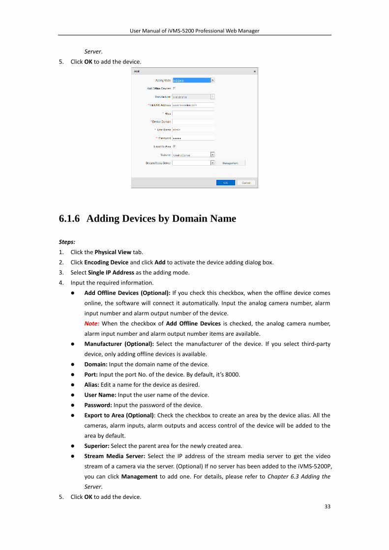
6.1.5 Adding Devices by HiDDNS .............................................................................. 32
6.1.6 Adding Devices by Domain Name ................................................................... 33
6.2 Adding the Behavior Analysis Server ....................................................................... 34
6.3 Adding the Server .................................................................................................... 35
6.4 Area Management .................................................................................................. 36
Chapter 7 Record Schedule Settings ........................................................................................ 40
7.1 Recording on Storage Devices of the Encoding Device ........................................... 40
7.1.1 Configuring Record Schedule Template........................................................... 41
7.2 Recording on Storage Server ................................................................................... 42
Chapter 8 Event Configuration ................................................................................................. 43
8.1 Configuring Camera Exception Alarm ..................................................................... 43
8.2 Configuring Line Crossing Detection ....................................................................... 45
8.3 Configuring Intrusion Detection .............................................................................. 46
8.4 Configuring Alarm Input Linkage ............................................................................. 47
8.5 Configuring Access Control Alarm Linkage .............................................................. 49
8.6 Configuring Device Exception Linkage ..................................................................... 50
8.7 Configuring Server Exception Linkage ..................................................................... 51
User Manual of iVMS-5200 Professional Web Manager
3
Chapter 9 User and System Management ............................................................................... 53
9.1 Role Management ................................................................................................... 53
9.2 User Management................................................................................................... 54
Chapter 10 System Configuration .............................................................................................. 57
10.1 Log Configuration .................................................................................................... 57
10.2 NTP Settings ............................................................................................................ 58
10.3 Email Settings .......................................................................................................... 58
10.4 CMP IP Address Settings.......................................................................................... 59
10.5 Active Directory Settings ......................................................................................... 59
Chapter 11 Appendix ................................................................................................................. 61
11.1 Important Ports ....................................................................................................... 61
11.2 FAQ .......................................................................................................................... 62
11.3 How to Allocate Storage Space for Storage Server.................................................. 63
User Manual of iVMS-5200 Professional Web Manager
4
Chapter 1 Overview
1.1 About This Document
This user manual is intended for the administrator of the iVMS-5200 Professional (hereafter simply as
iVMS-5200P). It guides you to establish and configure the surveillance system. Follow this manual to
perform the installation of the iVMS-5200P, activation of CMS, access of the iVMS-5200P and
configuration of the surveillance task via the provided web manager, etc. To ensure the properness of
usage and stability of the iVMS-5200P, please refer to the contents below and read the manual
carefully before installation and operation.
1.2 Introduction to iVMS-5200 Professional
iVMS-5200P is developed by HIKVISION for central management of video monitoring system and
features flexibility, scalability high reliability and powerful functions. Integrating with multiple
surveillance systems, iVMS-5200P provides the central management, information sharing, convenient
connection and multi-service cooperation. It is capable of adding devices for management, live view,
storage and playback of record files, VCA search, alarm linkage, etc..
The complete iVMS-5200P contains the following modules:
Note: You can install the modules according to actual needs.
Module Introduction
CMS (Central Management Server):
For detailed installation, please refer
to Chapter 3.1 Installing the Server
Modules.
a) Provide the unified authentication service for connecting
with the clients and servers.
b) Provide the centralized management for the users, roles,
permissions, surveillance devices, alarm device and
servers.
c) Provide the configuration interface for surveillance and
management module, and sub-systems.
d) Provide the log management and statistics function.
SMS (Stream Media Server)
(Optional):
For detailed installation, please refer
to Chapter 3.1 Installing the Server
Modules.
a) Forward and distribute the audio and video data of live
view.
b) Provide the function of live view via mobile control
client.
SS (Storage Server) (Optional):
For detailed installation, please refer
to Chapter 3.1 Installing the Server
Modules and Chapter 11.3 How to
Allocate Storage Space for Storage
Server.
a) Obtain the audio and video data stream via the SMS
(Stream Media Server) or directly from the connected
encoding device
b) Extract the index information and dump the audio and
video data to the storage device to realize the
centralized management of the mass video files.
User Manual of iVMS-5200 Professional Web Manager
5
Module Introduction
c) Provide the efficient, secure, convenient storage service
for pictures with storage efficiency of 10 pictures per
second.
MAG (Mobile Access Gateway)
(Optional):
For detailed installation, please refer
to Chapter 3.1 Installing the Server
Modules.
When setting the image quality as Fluent in Mobile Client, the
MAG can provide the following functions:
a) Convert and distribute the low bitrate stream when live
viewing the high-definition video via Mobile Client.
b) Transcode and distribute up to 24-ch high-definition
stream.
c) Ensure the high-definition live view and playback without
affecting the performance of the mobile phone.
Behavior Analysis (Optional):
For detailed installation, please refer
to Chapter 3.1 Installing the Server
Modules.
Provide line crossing detection and intrusion detection for the
network cameras that are added to the Behavior Analysis
server.
The following table lists the provided clients for accessing or management the iVMS-5200P.
Client Introduction
Control Client:
For detailed installation, please refer
to Chapter 3.3 Installing and
Uninstalling the Control Client.
iVMS-5200 Control Client is a C/S software which provides
multiple operating functionalities, including real-time live
view, PTZ control, video playback and download, alarm
receiving, log query, etc..
Web Client:
For detailed introduction, please
refer to the User Manual of
iVMS-5200 Control Client.
iVMS-5200 Web Client is a B/S software for accessing the
iVMS-5200P through web browser. It provides the
functionalities of live view, playback, and local configuration.
Web Manager:
For detailed running environment
for Web Manager, please refer to
Chapter 5.1 Open the Web Manager
and Login.
iVMS-5200 Web Manager is a B/S client for management of
iVMS-5200P. It provides multiple functionalities, including
device management, record schedule settings, event
configuration, user management, etc., for the iVMS-5200P to
manage the connected devices.
Mobile Client:
For detailed installation and
configuration, please refer to the
User Manual of iVMS-5260 Mobile
Client.
The iVMS-5260 Mobile Client is the mobile client software
designed for getting access to the iVMS-5200P via Wi-Fi, 2G,
3G and 4G network with mobile device, it fulfills the functions
of the devices connected to the iVMS-5200P, such as live view,
remote playback, PTZ control and so on.
1.3 Administrator Rights
When you install and run the server modules, clients and software, it is important that you have
administrator rights on the PCs or servers that should run these components. Otherwise, you cannot

User Manual of iVMS-5200 Professional Web Manager
6
install and configure the iVMS-5200P.
Consult your IT system administrator if in doubt about your rights.
User Manual of iVMS-5200 Professional Web Manager
7
Chapter 2 Getting Started
The following content describes the tasks typically involved in setting a working iVMS-5200P.
Note: The contents below may not cover the exact needs of your organization.
Verify Initial Configuration of Encoding Devices and other Servers
Before doing anything on iVMS-5200P, make sure the devices (cameras, DVR, storage server, etc.) you
are going to use are correctly installed and connected to the network, etc. as specified by the
manufacturers. Such initial configuration is required in order to be able to connect the devices to the
iVMS-5200P via network.
Install iVMS-5200P
Refer to Chapter 3 Installation and Uninstallation to for the detailed installation steps.
Open the Web Manager
Refer to Chapter 5.1 Open the Web Manager and Login.
Activate Your License
Refer to Chapter 4 Activating CMS for the operation of activating the license.
Add Devices to iVMS-5200P and Configure Area
iVMS-5200P can quickly scan your network for relevant encoding devices (cameras, DVR, etc.), and
add them to your system. Or you can add the devices by inputting the required information manually.
The devices added should be organized into areas for convenient management. Refer to Chapter 6
Resource Management.
Configure Record Schedule
The video files of the cameras to can be recorded on the storage device according to the configured
record schedule. The schedule can be set as continuous, alarm triggered or command triggered as
desired. Refer to Chapter 7 Record Schedule Settings.
Configure Events
The camera exception, device exception, server exception and the alarm input can trigger linkage
actions in iVMS-5200P. For example: when motion is detected, an audible warning appears or a
notification email is sent to you. Refer to Chapter 8 Event Configuration.
Configure Users
Now specify who should be able to access your iVMS-5200P, and how. You can set the different
permissions for the users to limit the operation of the iVMS-5200P. Refer to Chapter 9.1 Role
Management and Chapter 9.2 User Management.
User Manual of iVMS-5200 Professional Web Manager
8
Chapter 3 Installation and Uninstallation
The program file which is provided by HIKVISION contains 5 server modules and 1 client, including
iVMS-5200 Central Management Server, iVMS-5200 Storage Server, iVMS-5200 Stream Media Server,
iVMS-5200 Mobile Access Gateway, Behavior Analysis and iVMS-5200 Control Client. The server
modules can be installed on different servers or PCs separately, or you can install them on the same
server or PC as desired.
3.1 Installing the Server Modules
Before you start:
The SS must be installed on the 64-bit PC or server to work properly.
Running Environment
For CMS:
Operating System: Windows Server 2008 / Windows Server 2012 SP2 (64-bit); Windows 7 /
Windows 8 / Windows 8.1 (32/64-bit)
Processor: E5-2620 series processor with 6 cores (2.0 Ghz)
Memory: 8GB
HDD: Enterprise-level SATA disk with 600GB storage capacity
Network Controller: RJ45 Gigabit self-adaptive Ethernet interfaces
Note: We also provide a dedicated product for installing and running the CMS. For details, please
contact you dealer or our salesman.
For Other Servers
Operating System: Windows Server 2008 R2 (64-bit)
Processor: E3-1230 V2 series processor (3.3 GHz)
Memory: 8GB
HDD: Enterprise-level SATA disk with 500GB storage capacity
Network Controller: RJ45 Gigabit self-adaptive Ethernet interfaces
Note: We also provide dedicated products for installing and running the servers. For details, please
contact you dealer or our salesman.
Installation
Perform the following steps to install the server modules.
Steps:
1. Double-click the program file to enter the welcome panel of the InstallShield Wizard. Click
Next to start the InstallShield Wizard.
User Manual of iVMS-5200 Professional Web Manager
9
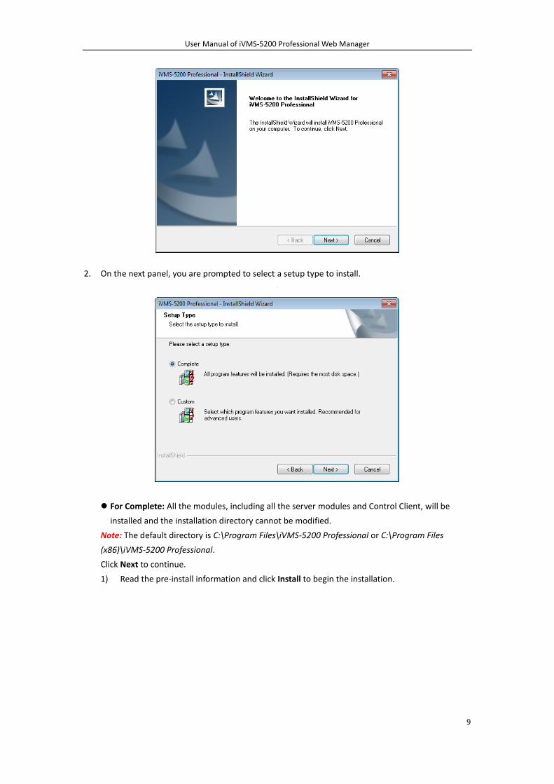
2. On the next panel, you are prompted to select a setup type to install.
For Complete: All the modules, including all the server modules and Control Client, will be
installed and the installation directory cannot be modified.
Note: The default directory is C:\Program Files\iVMS-5200 Professional or C:\Program Files
(x86)\iVMS-5200 Professional.
Click Next to continue.
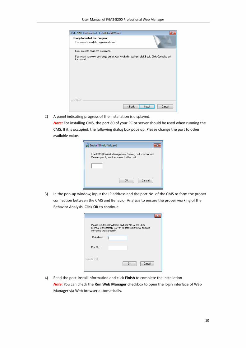
1) Read the pre-install information and click Install to begin the installation.
User Manual of iVMS-5200 Professional Web Manager
10
2) A panel indicating progress of the installation is displayed.
Note: For installing CMS, the port 80 of your PC or server should be used when running the
CMS. If it is occupied, the following dialog box pops up. Please change the port to other
available value.
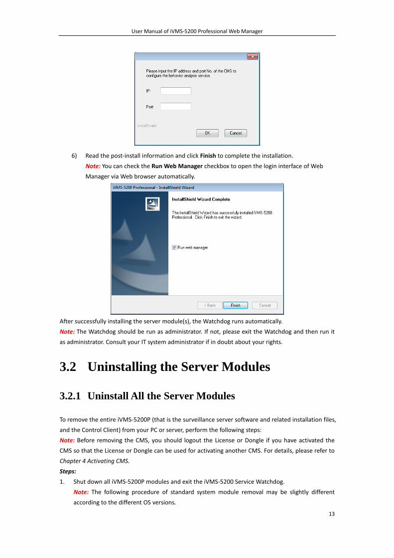
3) In the pop-up window, input the IP address and the port No. of the CMS to form the proper
connection between the CMS and Behavior Analysis to ensure the proper working of the
Behavior Analysis. Click OK to continue.
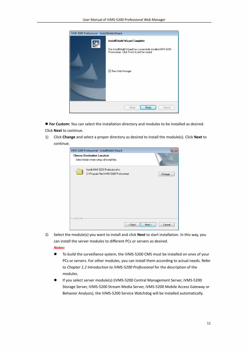
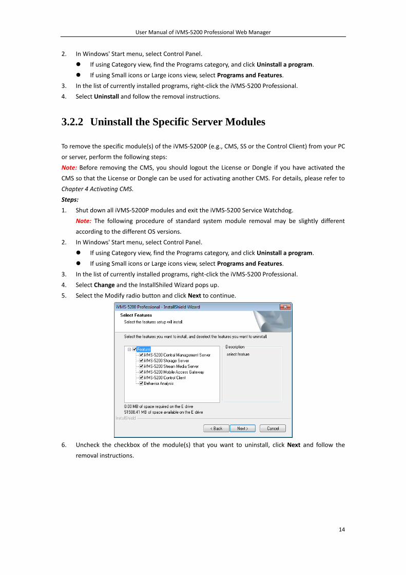
4) Read the post-install information and click Finish to complete the installation.
Note: You can check the Run Web Manager checkbox to open the login interface of Web
Manager via Web browser automatically.
User Manual of iVMS-5200 Professional Web Manager
11
For Custom: You can select the installation directory and modules to be installed as desired.
Click Next to continue.
1) Click Change and select a proper directory as desired to install the module(s). Click Next to
continue.
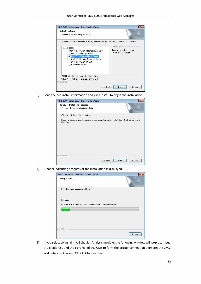
2) Select the module(s) you want to install and click Next to start installation. In this way, you
can install the server modules to different PCs or servers as desired.
Notes:
To build the surveillance system, the iVMS-5200 CMS must be installed on ones of your
PCs or servers. For other modules, you can install them according to actual needs. Refer
to Chapter 1.2 Introduction to iVMS-5200 Professional for the description of the
modules.
If you select server module(s) (iVMS-5200 Central Management Server, iVMS-5200
Storage Server, iVMS-5200 Stream Media Server, iVMS-5200 Mobile Access Gateway or
Behavior Analysis), the iVMS-5200 Service Watchdog will be installed automatically.
User Manual of iVMS-5200 Professional Web Manager
12
3) Read the pre-install information and click Install to begin the installation.
4) A panel indicating progress of the installation is displayed.
5) If you select to install the Behavior Analysis module, the following window will pop up. Input
the IP address and the port No. of the CMS to form the proper connection between the CMS
and Behavior Analysis. Click OK to continue.
User Manual of iVMS-5200 Professional Web Manager
13
6) Read the post-install information and click Finish to complete the installation.
Note: You can check the Run Web Manager checkbox to open the login interface of Web
Manager via Web browser automatically.
After successfully installing the server module(s), the Watchdog runs automatically.
Note: The Watchdog should be run as administrator. If not, please exit the Watchdog and then run it
as administrator. Consult your IT system administrator if in doubt about your rights.
3.2 Uninstalling the Server Modules
3.2.1 Uninstall All the Server Modules
To remove the entire iVMS-5200P (that is the surveillance server software and related installation files,
and the Control Client) from your PC or server, perform the following steps:
Note: Before removing the CMS, you should logout the License or Dongle if you have activated the
CMS so that the License or Dongle can be used for activating another CMS. For details, please refer to
Chapter 4 Activating CMS.
Steps:
1. Shut down all iVMS-5200P modules and exit the iVMS-5200 Service Watchdog.
Note: The following procedure of standard system module removal may be slightly different
according to the different OS versions.
User Manual of iVMS-5200 Professional Web Manager
14
2. In Windows' Start menu, select Control Panel.
If using Category view, find the Programs category, and click Uninstall a program.
If using Small icons or Large icons view, select Programs and Features.
3. In the list of currently installed programs, right-click the iVMS-5200 Professional.
4. Select Uninstall and follow the removal instructions.
3.2.2 Uninstall the Specific Server Modules
To remove the specific module(s) of the iVMS-5200P (e.g., CMS, SS or the Control Client) from your PC
or server, perform the following steps:
Note: Before removing the CMS, you should logout the License or Dongle if you have activated the
CMS so that the License or Dongle can be used for activating another CMS. For details, please refer to
Chapter 4 Activating CMS.
Steps:
1. Shut down all iVMS-5200P modules and exit the iVMS-5200 Service Watchdog.
Note: The following procedure of standard system module removal may be slightly different
according to the different OS versions.
2. In Windows' Start menu, select Control Panel.
If using Category view, find the Programs category, and click Uninstall a program.
If using Small icons or Large icons view, select Programs and Features.
3. In the list of currently installed programs, right-click the iVMS-5200 Professional.
4. Select Change and the InstallShiled Wizard pops up.
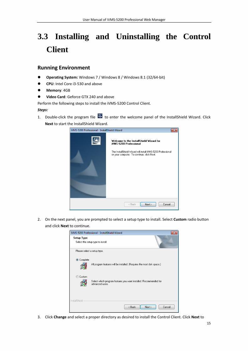
5. Select the Modify radio button and click Next to continue.
6. Uncheck the checkbox of the module(s) that you want to uninstall, click Next and follow the
removal instructions.
User Manual of iVMS-5200 Professional Web Manager
15
3.3 Installing and Uninstalling the Control
Client
Running Environment
Operating System: Windows 7 / Windows 8 / Windows 8.1 (32/64-bit)
CPU: Intel Core i3-530 and above
Memory: 4GB
Video Card: Geforce GTX 240 and above
Perform the following steps to install the iVMS-5200 Control Client.
Steps:
1. Double-click the program file to enter the welcome panel of the InstallShield Wizard. Click
Next to start the InstallShield Wizard.
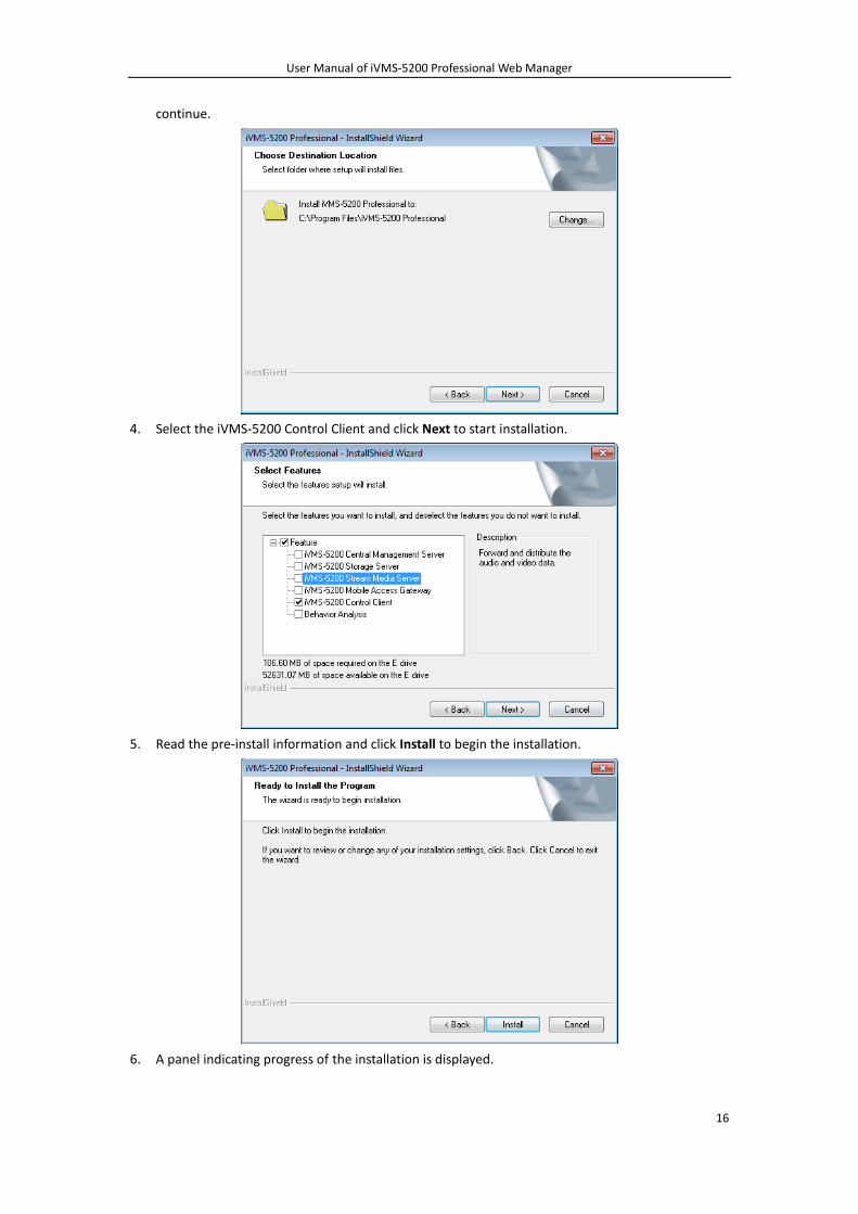
2. On the next panel, you are prompted to select a setup type to install. Select Custom radio button
and click Next to continue.
3. Click Change and select a proper directory as desired to install the Control Client. Click Next to
User Manual of iVMS-5200 Professional Web Manager
16
continue.
4. Select the iVMS-5200 Control Client and click Next to start installation.
5. Read the pre-install information and click Install to begin the installation.
6. A panel indicating progress of the installation is displayed.
User Manual of iVMS-5200 Professional Web Manager
17
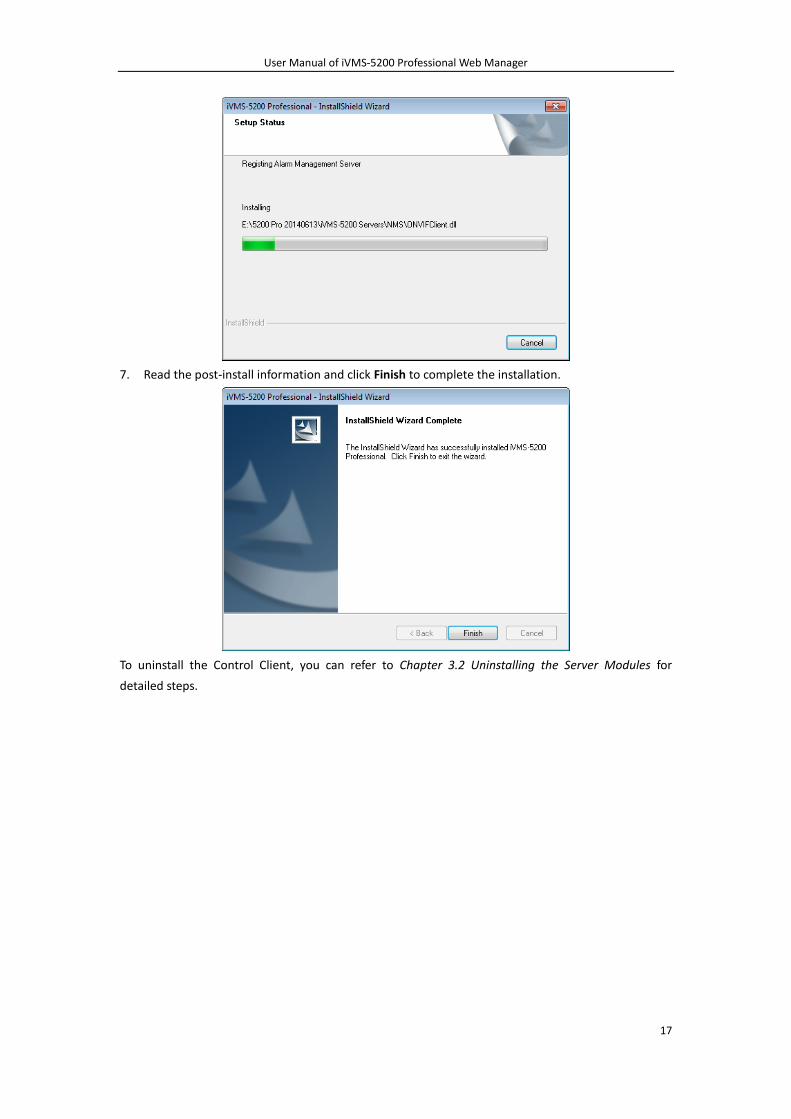
7. Read the post-install information and click Finish to complete the installation.
To uninstall the Control Client, you can refer to Chapter 3.2 Uninstalling the Server Modules for
detailed steps.
User Manual of iVMS-5200 Professional Web Manager
18
Chapter 4 Activating CMS
After you install the iVMS-5200P, you get a temporary License for certain number of connected
cameras within a certain time period. This is called the trial period. If trial period have expired and the
CMS has not been activated, the iVMS-5200P will stop working.
To ensure the proper use of the iVMS-5200P, you should activate the CMS before the trial period ends.
Notes:
1) If you do not want to activate the CMS now, you can skip this chapter and perform this operation
according to actual needs.
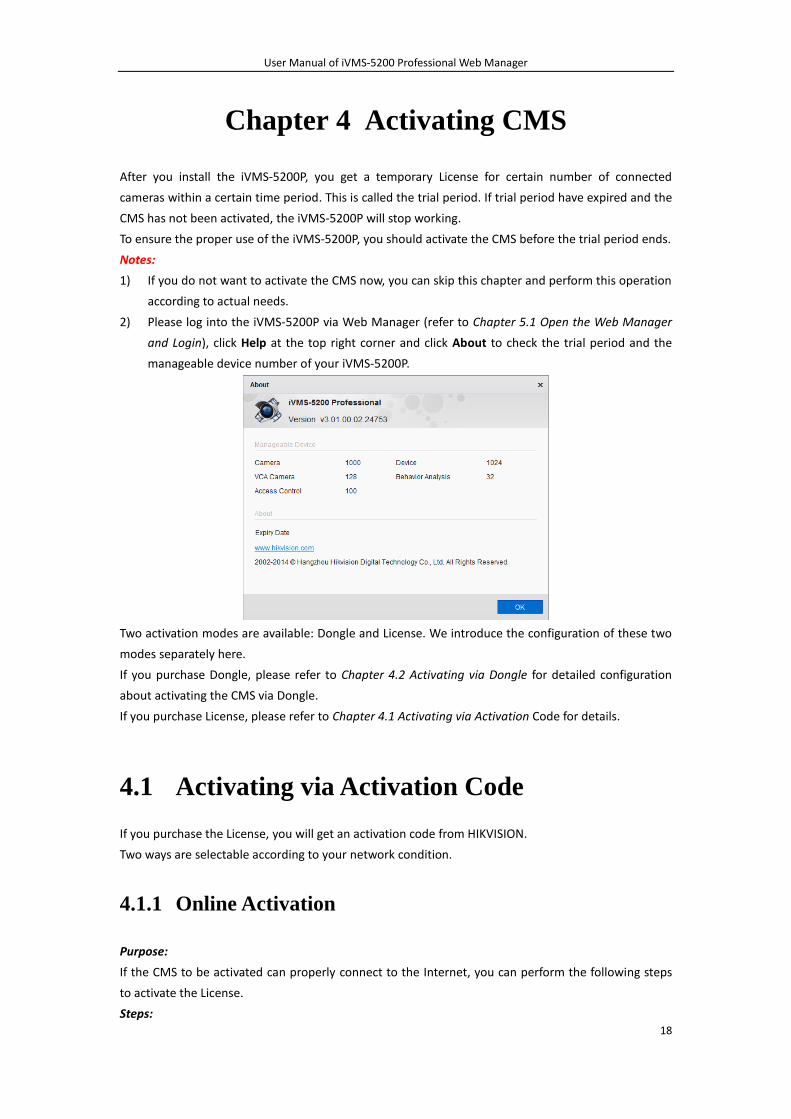
2) Please log into the iVMS-5200P via Web Manager (refer to Chapter 5.1 Open the Web Manager
and Login), click Help at the top right corner and click About to check the trial period and the
manageable device number of your iVMS-5200P.
Two activation modes are available: Dongle and License. We introduce the configuration of these two
modes separately here.
If you purchase Dongle, please refer to Chapter 4.2 Activating via Dongle for detailed configuration
about activating the CMS via Dongle.
If you purchase License, please refer to Chapter 4.1 Activating via Activation Code for details.
4.1 Activating via Activation Code
If you purchase the License, you will get an activation code from HIKVISION.
Two ways are selectable according to your network condition.
4.1.1 Online Activation
Purpose:
If the CMS to be activated can properly connect to the Internet, you can perform the following steps
to activate the License.
Steps:
User Manual of iVMS-5200 Professional Web Manager
19
1. Log into the iVMS-5200P via Web Manager. Please refer to Chapter 5.1 Open the Web Manager
and Login.
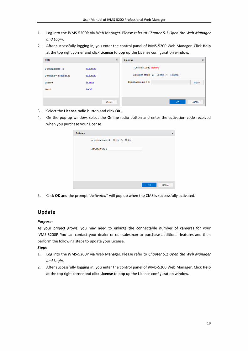
2. After successfully logging in, you enter the control panel of iVMS-5200 Web Manager. Click Help
at the top right corner and click License to pop up the License configuration window.
3. Select the License radio button and click OK.
4. On the pop-up window, select the Online radio button and enter the activation code received
when you purchase your License.
5. Click OK and the prompt “Activated” will pop up when the CMS is successfully activated.
Update
Purpose:
As your project grows, you may need to enlarge the connectable number of cameras for your
iVMS-5200P. You can contact your dealer or our salesman to purchase additional features and then
perform the following steps to update your License.
Steps
1. Log into the iVMS-5200P via Web Manager. Please refer to Chapter 5.1 Open the Web Manager
and Login.
2. After successfully logging in, you enter the control panel of iVMS-5200 Web Manager. Click Help
at the top right corner and click License to pop up the License configuration window.
User Manual of iVMS-5200 Professional Web Manager
20
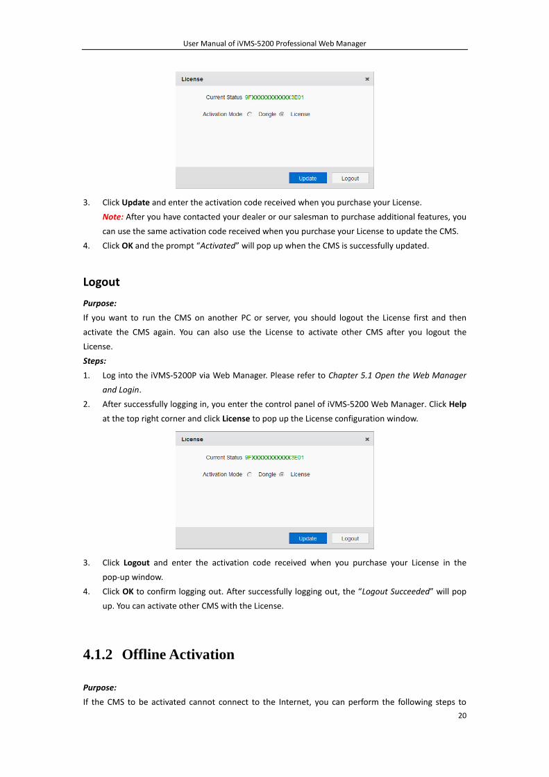
3. Click Update and enter the activation code received when you purchase your License.
Note: After you have contacted your dealer or our salesman to purchase additional features, you
can use the same activation code received when you purchase your License to update the CMS.
4. Click OK and the prompt “Activated” will pop up when the CMS is successfully updated.
Logout
Purpose:
If you want to run the CMS on another PC or server, you should logout the License first and then
activate the CMS again. You can also use the License to activate other CMS after you logout the
License.
Steps:
1. Log into the iVMS-5200P via Web Manager. Please refer to Chapter 5.1 Open the Web Manager
and Login.
2. After successfully logging in, you enter the control panel of iVMS-5200 Web Manager. Click Help
at the top right corner and click License to pop up the License configuration window.
3. Click Logout and enter the activation code received when you purchase your License in the
pop-up window.
4. Click OK to confirm logging out. After successfully logging out, the “Logout Succeeded” will pop
up. You can activate other CMS with the License.
4.1.2 Offline Activation
Purpose:
If the CMS to be activated cannot connect to the Internet, you can perform the following steps to
User Manual of iVMS-5200 Professional Web Manager
21
activate the License.
Note: Offline License Activation Utility will also be provided by HIKVISION for offline activation.
Steps:
1. Log into the iVMS-5200P via Web Manager. Please refer to Chapter 5.1 Open the Web Manager
and Login.
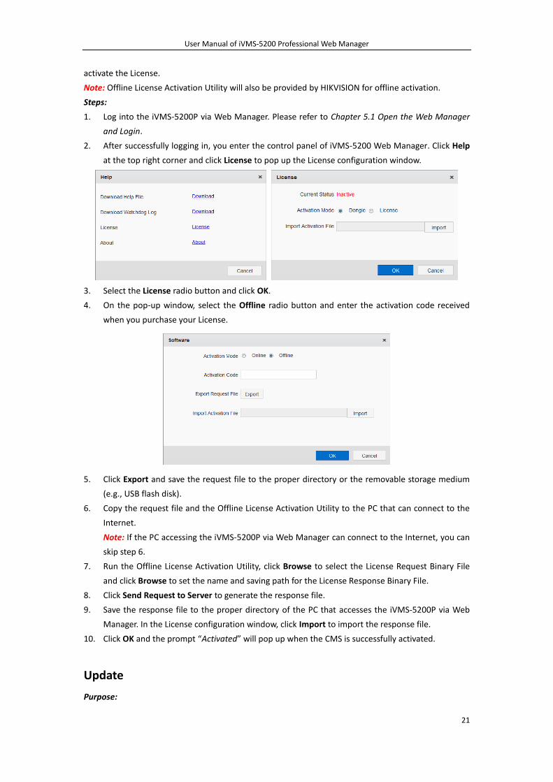
2. After successfully logging in, you enter the control panel of iVMS-5200 Web Manager. Click Help
at the top right corner and click License to pop up the License configuration window.
3. Select the License radio button and click OK.
4. On the pop-up window, select the Offline radio button and enter the activation code received
when you purchase your License.
5. Click Export and save the request file to the proper directory or the removable storage medium
(e.g., USB flash disk).
6. Copy the request file and the Offline License Activation Utility to the PC that can connect to the
Internet.
Note: If the PC accessing the iVMS-5200P via Web Manager can connect to the Internet, you can
skip step 6.
7. Run the Offline License Activation Utility, click Browse to select the License Request Binary File
and click Browse to set the name and saving path for the License Response Binary File.
8. Click Send Request to Server to generate the response file.
9. Save the response file to the proper directory of the PC that accesses the iVMS-5200P via Web
Manager. In the License configuration window, click Import to import the response file.
10. Click OK and the prompt “Activated” will pop up when the CMS is successfully activated.
Update
Purpose:
User Manual of iVMS-5200 Professional Web Manager
22
As your project grows, you may need to enlarge the connectable number of cameras for your
iVMS-5200P. You can contact your dealer or our salesman to purchase additional features and then
perform the following steps to update your License.
Steps
1. Log into the iVMS-5200P via Web Manager. Please refer to Chapter 5.1 Open the Web Manager
and Login.
2. After successfully logging in, you enter the control panel of iVMS-5200 Web Manager. Click Help
at the top right corner and click License to pop up the License configuration window.
3. Click Update and enter the activation code received when you purchase your License.
Note: After you contact your dealer or our salesman to purchase additional features, you can use
the activation code received when you purchase your License to update the CMS.
4. Click Export and save the request file to the proper directory or the removable storage medium
(e.g., USB flash disk).
5. Copy the request file and the Offline License Activation Utility to the PC that can connect to the
Internet.
Note: If the PC accessing the iVMS-5200P via Web Manager can connect to the Internet, you can
skip step 5.
6. Run the Offline License Activation Utility, click Browse to select the License Request Binary File
and click Browse to set the name and saving path for the License Response Binary File.
7. Click Send Request to Server to generate the response file.
8. Save the response file to the proper directory of the PC that accesses the iVMS-5200P via Web
Manager. In the License configuration window, click Import to import the response file.
9. Click OK and the prompt “Activated” will pop up when the CMS is successfully updated.
Logout
Purpose:
If you want to run the CMS on another PC or server, you should logout the License first and then
activate the CMS again. You can also use the License to activate other CMS after you logout the
License.
Steps:
1. Log into the iVMS-5200P via Web Manager. Please refer to Chapter 5.1 Open the Web Manager
and Login.
2. After successfully logging in, you enter the control panel of iVMS-5200 Web Manager. Click Help
at the top right corner and click License to pop up the License configuration window.
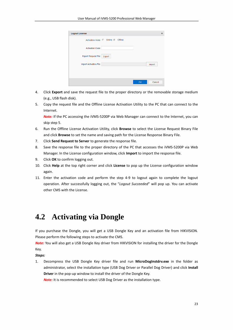
3. Click Logout and on the pop-up window, select the Offline radio button and enter the activation
code received when you purchase your License.
User Manual of iVMS-5200 Professional Web Manager
23
4. Click Export and save the request file to the proper directory or the removable storage medium
(e.g., USB flash disk).
5. Copy the request file and the Offline License Activation Utility to the PC that can connect to the
Internet.
Note: If the PC accessing the iVMS-5200P via Web Manager can connect to the Internet, you can
skip step 5.
6. Run the Offline License Activation Utility, click Browse to select the License Request Binary File
and click Browse to set the name and saving path for the License Response Binary File.
7. Click Send Request to Server to generate the response file.
8. Save the response file to the proper directory of the PC that accesses the iVMS-5200P via Web
Manager. In the License configuration window, click Import to import the response file.
9. Click OK to confirm logging out.
10. Click Help at the top right corner and click License to pop up the License configuration window
again.
11. Enter the activation code and perform the step 4-9 to logout again to complete the logout
operation. After successfully logging out, the “Logout Succeeded” will pop up. You can activate
other CMS with the License.
4.2 Activating via Dongle
If you purchase the Dongle, you will get a USB Dongle Key and an activation file from HIKVISION.
Please perform the following steps to activate the CMS.
Note: You will also get a USB Dongle Key driver from HIKVISION for installing the driver for the Dongle
Key.
Steps:
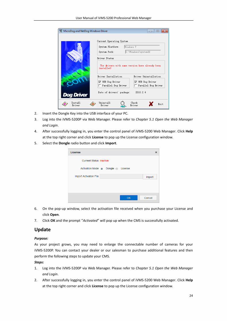
1. Decompress the USB Dongle Key driver file and run MicroDogInstdrv.exe in the folder as
administrator, select the installation type (USB Dog Driver or Parallel Dog Driver) and click Install
Driver in the pop-up window to install the driver of the Dongle Key.
Note: It is recommended to select USB Dog Driver as the installation type.
User Manual of iVMS-5200 Professional Web Manager
24
2. Insert the Dongle Key into the USB interface of your PC.
3. Log into the iVMS-5200P via Web Manager. Please refer to Chapter 5.1 Open the Web Manager
and Login.
4. After successfully logging in, you enter the control panel of iVMS-5200 Web Manager. Click Help
at the top right corner and click License to pop up the License configuration window.
5. Select the Dongle radio button and click Import.
6. On the pop-up window, select the activation file received when you purchase your License and
click Open.
7. Click OK and the prompt “Activated” will pop up when the CMS is successfully activated.
Update
Purpose:
As your project grows, you may need to enlarge the connectable number of cameras for your
iVMS-5200P. You can contact your dealer or our salesman to purchase additional features and then
perform the following steps to update your CMS.
Steps:
1. Log into the iVMS-5200P via Web Manager. Please refer to Chapter 5.1 Open the Web Manager
and Login.
2. After successfully logging in, you enter the control panel of iVMS-5200 Web Manager. Click Help
at the top right corner and click License to pop up the License configuration window.
User Manual of iVMS-5200 Professional Web Manager
25
3. Click Import and on the pop-up window, select the new activation file received after you
purchase additional features and click Open.
4. Click OK and the prompt “Activated” will pop up when the CMS is successfully updated.
Logout
Purpose:
If you want to run the CMS on another PC or server, you should logout the License first and then
activate the CMS again. You can also use the License to activate other CMS after you logout the
License.
Steps:
1. Log into the iVMS-5200P via Web Manager. Please refer to Chapter 5.1 Open the Web Manager
and Login.
2. After successfully logging in, you enter the control panel of iVMS-5200 Web Manager. Click Help
at the top right corner and click License to pop up the License configuration window.
3. Click Logout. After successfully logging out, the “Logout Succeeded” will pop up. You can activate
other CMS with the License.
User Manual of iVMS-5200 Professional Web Manager
26
Chapter 5 Accessing the iVMS-5200P
5.1 Open the Web Manager and Login
Running Environment
Operating System: Microsoft Windows 7 / Windows 8 / Windows 8.1 (32 / 64-bit)
CPU: Intel Pentium IV 3.0 GHz or above
Memory: 1G or above
Video Card: RADEON X700 Series
Web Browser: IE 8/9/10/11, Chrome 34/35, Firefox 28/29
Steps:
1. In the address bar of the web browser, input the address of the CMS (Central Management Server)
and press the Enter key. A login window will pop up.
Note: The address is in the format of http://IP address of CMS/manager.
Example: If the IP address of CMS is 172.6.21.96, and you should enter
http://172.6.21.96/manager in the address bar.
2. For the first time to login, you should install the plug-in before you can access the functions.
1) Click Download Plug-in, save the plug-in file and then close the web browser.
2) Install the plug-in according to the prompt.
3) After the installation, re-open the web browser and log into the iVMS-5200P (step 1).
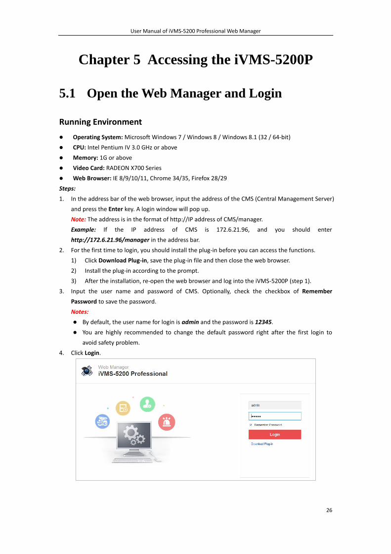
3. Input the user name and password of CMS. Optionally, check the checkbox of Remember
Password to save the password.
Notes:
By default, the user name for login is admin and the password is 12345.
You are highly recommended to change the default password right after the first login to
avoid safety problem.
4. Click Login.
User Manual of iVMS-5200 Professional Web Manager
27
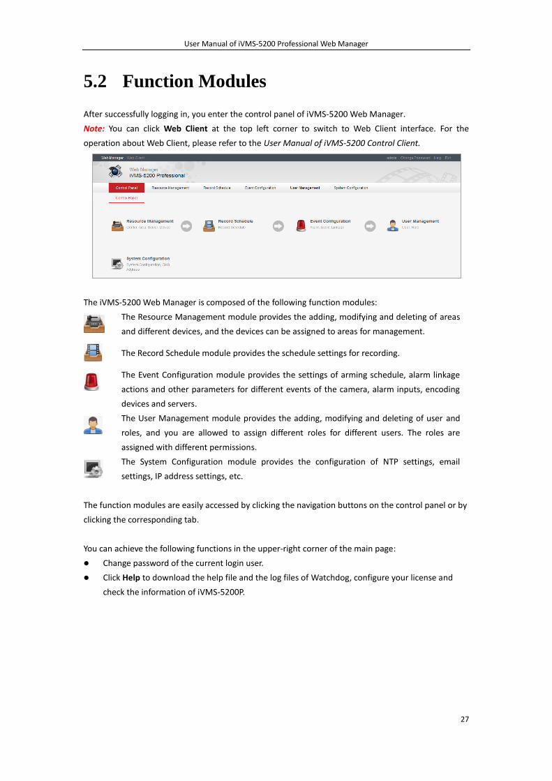
5.2 Function Modules
After successfully logging in, you enter the control panel of iVMS-5200 Web Manager.
Note: You can click Web Client at the top left corner to switch to Web Client interface. For the
operation about Web Client, please refer to the User Manual of iVMS-5200 Control Client.
The iVMS-5200 Web Manager is composed of the following function modules:
The Resource Management module provides the adding, modifying and deleting of areas
and different devices, and the devices can be assigned to areas for management.
The Record Schedule module provides the schedule settings for recording.
The Event Configuration module provides the settings of arming schedule, alarm linkage
actions and other parameters for different events of the camera, alarm inputs, encoding
devices and servers.
The User Management module provides the adding, modifying and deleting of user and
roles, and you are allowed to assign different roles for different users. The roles are
assigned with different permissions.
The System Configuration module provides the configuration of NTP settings, email
settings, IP address settings, etc.
The function modules are easily accessed by clicking the navigation buttons on the control panel or by
clicking the corresponding tab.
You can achieve the following functions in the upper-right corner of the main page:
Change password of the current login user.
Click Help to download the help file and the log files of Watchdog, configure your license and
check the information of iVMS-5200P.
User Manual of iVMS-5200 Professional Web Manager
28
Chapter 6 Resource Management
6.1 Adding the Encoding Device
Purpose:
Before you can live view, play back via the Control Client or set recording schedule, event
configuration via Web Manager, you need to add devices to the iVMS-5200P and manage them by
areas.
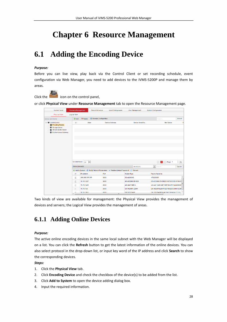
Click the icon on the control panel,
or click Physical View under Resource Management tab to open the Resource Management page.
Two kinds of view are available for management: the Physical View provides the management of
devices and servers; the Logical View provides the management of areas.
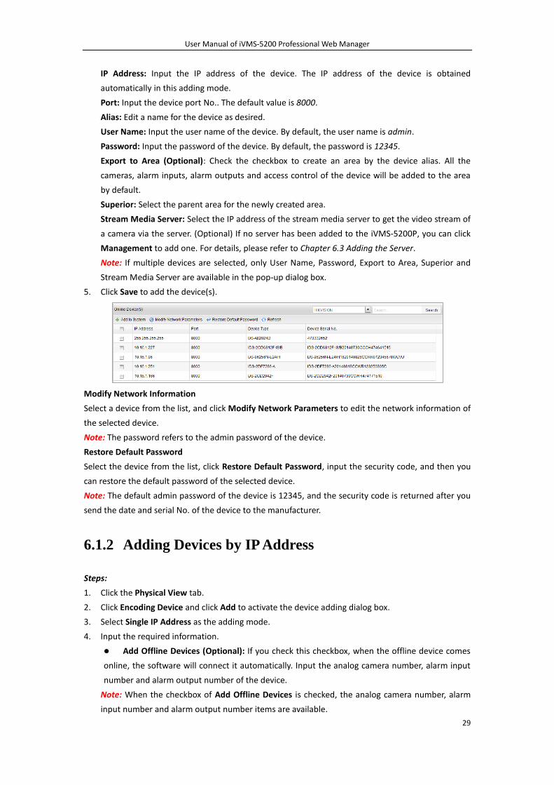
6.1.1 Adding Online Devices
Purpose:
The active online encoding devices in the same local subnet with the Web Manager will be displayed
on a list. You can click the Refresh button to get the latest information of the online devices. You can
also select protocol in the drop-down list, or input key word of the IP address and click Search to show
the corresponding devices.
Steps:
1. Click the Physical View tab.
2. Click Encoding Device and check the checkbox of the device(s) to be added from the list.
3. Click Add to System to open the device adding dialog box.
4. Input the required information.
User Manual of iVMS-5200 Professional Web Manager
29
IP Address: Input the IP address of the device. The IP address of the device is obtained
automatically in this adding mode.
Port: Input the device port No.. The default value is 8000.
Alias: Edit a name for the device as desired.
User Name: Input the user name of the device. By default, the user name is admin.
Password: Input the password of the device. By default, the password is 12345.
Export to Area (Optional): Check the checkbox to create an area by the device alias. All the
cameras, alarm inputs, alarm outputs and access control of the device will be added to the area
by default.
Superior: Select the parent area for the newly created area.
Stream Media Server: Select the IP address of the stream media server to get the video stream of
a camera via the server. (Optional) If no server has been added to the iVMS-5200P, you can click
Management to add one. For details, please refer to Chapter 6.3 Adding the Server.
Note: If multiple devices are selected, only User Name, Password, Export to Area, Superior and
Stream Media Server are available in the pop-up dialog box.
5. Click Save to add the device(s).
Modify Network Information
Select a device from the list, and click Modify Network Parameters to edit the network information of
the selected device.
Note: The password refers to the admin password of the device.
Restore Default Password
Select the device from the list, click Restore Default Password, input the security code, and then you
can restore the default password of the selected device.
Note: The default admin password of the device is 12345, and the security code is returned after you
send the date and serial No. of the device to the manufacturer.
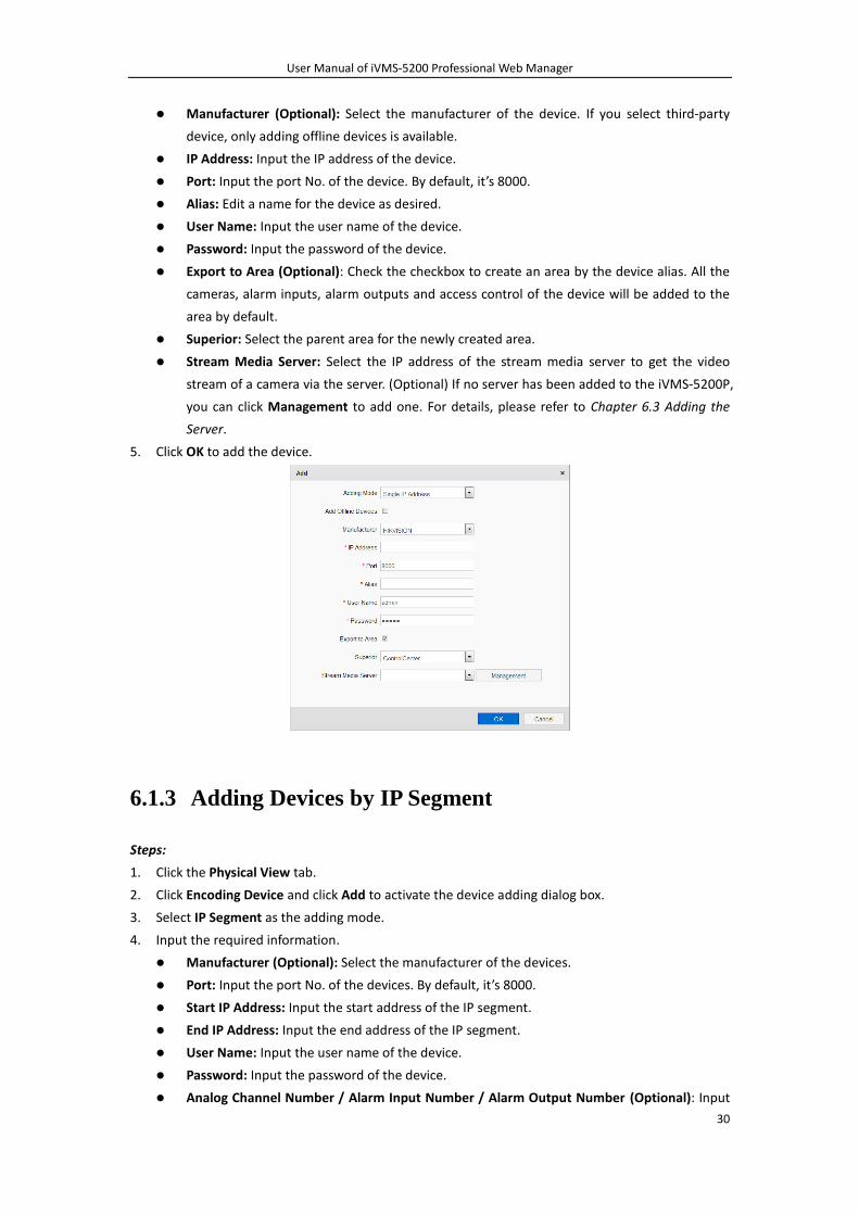
6.1.2 Adding Devices by IP Address
Steps:
1. Click the Physical View tab.
2. Click Encoding Device and click Add to activate the device adding dialog box.
3. Select Single IP Address as the adding mode.
4. Input the required information.
Add Offline Devices (Optional): If you check this checkbox, when the offline device comes
online, the software will connect it automatically. Input the analog camera number, alarm input
number and alarm output number of the device.
Note: When the checkbox of Add Offline Devices is checked, the analog camera number, alarm
input number and alarm output number items are available.
User Manual of iVMS-5200 Professional Web Manager
30
Manufacturer (Optional): Select the manufacturer of the device. If you select third-party
device, only adding offline devices is available.
IP Address: Input the IP address of the device.
Port: Input the port No. of the device. By default, it’s 8000.
Alias: Edit a name for the device as desired.
User Name: Input the user name of the device.
Password: Input the password of the device.
Export to Area (Optional): Check the checkbox to create an area by the device alias. All the
cameras, alarm inputs, alarm outputs and access control of the device will be added to the
area by default.
Superior: Select the parent area for the newly created area.
Stream Media Server: Select the IP address of the stream media server to get the video
stream of a camera via the server. (Optional) If no server has been added to the iVMS-5200P,
you can click Management to add one. For details, please refer to Chapter 6.3 Adding the
Server.
5. Click OK to add the device.
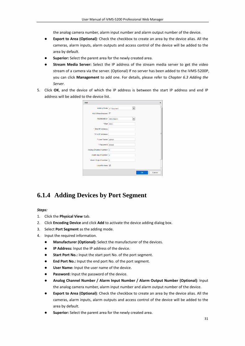
6.1.3 Adding Devices by IP Segment
Steps:
1. Click the Physical View tab.
2. Click Encoding Device and click Add to activate the device adding dialog box.
3. Select IP Segment as the adding mode.
4. Input the required information.
Manufacturer (Optional): Select the manufacturer of the devices.
Port: Input the port No. of the devices. By default, it’s 8000.
Start IP Address: Input the start address of the IP segment.
End IP Address: Input the end address of the IP segment.
User Name: Input the user name of the device.
Password: Input the password of the device.
Analog Channel Number / Alarm Input Number / Alarm Output Number (Optional): Input
User Manual of iVMS-5200 Professional Web Manager
31
the analog camera number, alarm input number and alarm output number of the device.
Export to Area (Optional): Check the checkbox to create an area by the device alias. All the
cameras, alarm inputs, alarm outputs and access control of the device will be added to the
area by default.
Superior: Select the parent area for the newly created area.
Stream Media Server: Select the IP address of the stream media server to get the video
stream of a camera via the server. (Optional) If no server has been added to the iVMS-5200P,
you can click Management to add one. For details, please refer to Chapter 6.3 Adding the
Server.
5. Click OK, and the device of which the IP address is between the start IP address and end IP
address will be added to the device list.
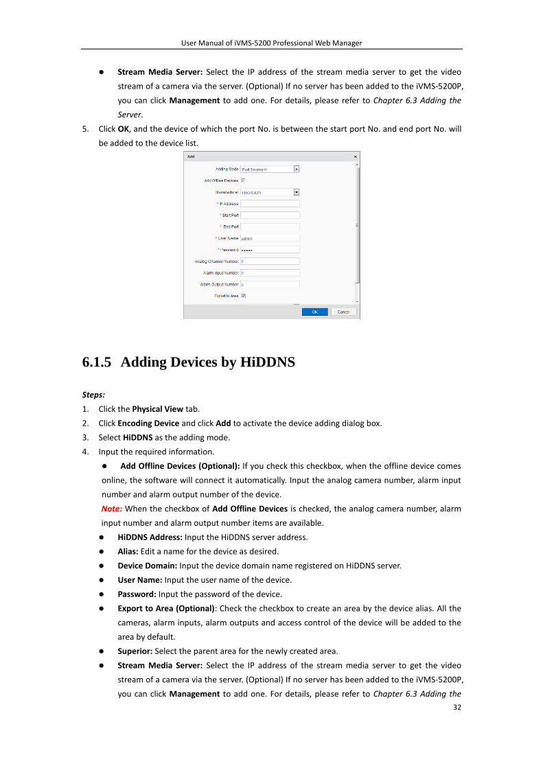
6.1.4 Adding Devices by Port Segment
Steps:
1. Click the Physical View tab.
2. Click Encoding Device and click Add to activate the device adding dialog box.
3. Select Port Segment as the adding mode.
4. Input the required information.
Manufacturer (Optional): Select the manufacturer of the devices.
IP Address: Input the IP address of the device.
Start Port No.: Input the start port No. of the port segment.
End Port No.: Input the end port No. of the port segment.
User Name: Input the user name of the device.
Password: Input the password of the device.
Analog Channel Number / Alarm Input Number / Alarm Output Number (Optional): Input
the analog camera number, alarm input number and alarm output number of the device.
Export to Area (Optional): Check the checkbox to create an area by the device alias. All the
cameras, alarm inputs, alarm outputs and access control of the device will be added to the
area by default.
Superior: Select the parent area for the newly created area.
User Manual of iVMS-5200 Professional Web Manager
32
Stream Media Server: Select the IP address of the stream media server to get the video
stream of a camera via the server. (Optional) If no server has been added to the iVMS-5200P,
you can click Management to add one. For details, please refer to Chapter 6.3 Adding the
Server.
5. Click OK, and the device of which the port No. is between the start port No. and end port No. will
be added to the device list.
6.1.5 Adding Devices by HiDDNS
Steps:
1. Click the Physical View tab.
2. Click Encoding Device and click Add to activate the device adding dialog box.
3. Select HiDDNS as the adding mode.
4. Input the required information.
Add Offline Devices (Optional): If you check this checkbox, when the offline device comes
online, the software will connect it automatically. Input the analog camera number, alarm input
number and alarm output number of the device.
Note: When the checkbox of Add Offline Devices is checked, the analog camera number, alarm
input number and alarm output number items are available.
HiDDNS Address: Input the HiDDNS server address.
Alias: Edit a name for the device as desired.
Device Domain: Input the device domain name registered on HiDDNS server.
User Name: Input the user name of the device.
Password: Input the password of the device.
Export to Area (Optional): Check the checkbox to create an area by the device alias. All the
cameras, alarm inputs, alarm outputs and access control of the device will be added to the
area by default.
Superior: Select the parent area for the newly created area.
Stream Media Server: Select the IP address of the stream media server to get the video
stream of a camera via the server. (Optional) If no server has been added to the iVMS-5200P,
you can click Management to add one. For details, please refer to Chapter 6.3 Adding the
User Manual of iVMS-5200 Professional Web Manager
33
Server.
5. Click OK to add the device.
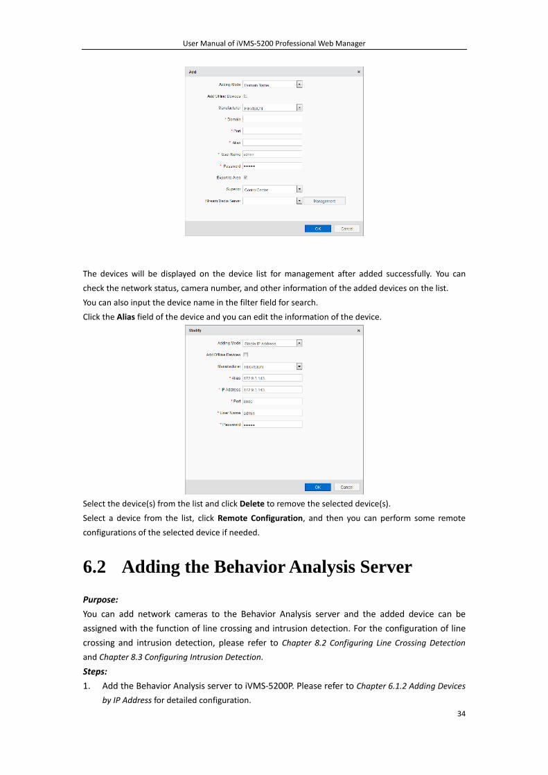
6.1.6 Adding Devices by Domain Name
Steps:
1. Click the Physical View tab.
2. Click Encoding Device and click Add to activate the device adding dialog box.
3. Select Single IP Address as the adding mode.
4. Input the required information.
Add Offline Devices (Optional): If you check this checkbox, when the offline device comes
online, the software will connect it automatically. Input the analog camera number, alarm
input number and alarm output number of the device.
Note: When the checkbox of Add Offline Devices is checked, the analog camera number,
alarm input number and alarm output number items are available.
Manufacturer (Optional): Select the manufacturer of the device. If you select third-party
device, only adding offline devices is available.
Domain: Input the domain name of the device.
Port: Input the port No. of the device. By default, it’s 8000.
Alias: Edit a name for the device as desired.
User Name: Input the user name of the device.
Password: Input the password of the device.
Export to Area (Optional): Check the checkbox to create an area by the device alias. All the
cameras, alarm inputs, alarm outputs and access control of the device will be added to the
area by default.
Superior: Select the parent area for the newly created area.
Stream Media Server: Select the IP address of the stream media server to get the video
stream of a camera via the server. (Optional) If no server has been added to the iVMS-5200P,
you can click Management to add one. For details, please refer to Chapter 6.3 Adding the
Server.
5. Click OK to add the device.
User Manual of iVMS-5200 Professional Web Manager
34
The devices will be displayed on the device list for management after added successfully. You can
check the network status, camera number, and other information of the added devices on the list.
You can also input the device name in the filter field for search.
Click the Alias field of the device and you can edit the information of the device.
Select the device(s) from the list and click Delete to remove the selected device(s).
Select a device from the list, click Remote Configuration, and then you can perform some remote
configurations of the selected device if needed.
6.2 Adding the Behavior Analysis Server
Purpose:
You can add network cameras to the Behavior Analysis server and the added device can be
assigned with the function of line crossing and intrusion detection. For the configuration of line
crossing and intrusion detection, please refer to Chapter 8.2 Configuring Line Crossing Detection
and Chapter 8.3 Configuring Intrusion Detection.
Steps:
1. Add the Behavior Analysis server to iVMS-5200P. Please refer to Chapter 6.1.2 Adding Devices
by IP Address for detailed configuration.
User Manual of iVMS-5200 Professional Web Manager
35
Note: The IP address of Behavior Analysis server refers to the IP address of the PC or server
that installs the Behavior Analysis module.
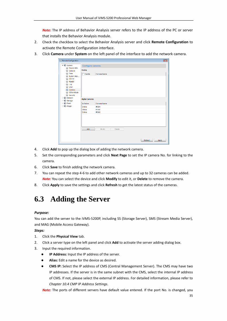
2. Check the checkbox to select the Behavior Analysis server and click Remote Configuration to
activate the Remote Configuration interface.
3. Click Camera under System on the left panel of the interface to add the network camera.
4. Click Add to pop up the dialog box of adding the network camera.
5. Set the corresponding parameters and click Next Page to set the IP camera No. for linking to the
camera.
6. Click Save to finish adding the network camera.
7. You can repeat the step 4-6 to add other network cameras and up to 32 cameras can be added.
Note: You can select the device and click Modify to edit it, or Delete to remove the camera.
8. Click Apply to save the settings and click Refresh to get the latest status of the cameras.
6.3 Adding the Server
Purpose:
You can add the server to the iVMS-5200P, including SS (Storage Server), SMS (Stream Media Server),
and MAG (Mobile Access Gateway).
Steps:
1. Click the Physical View tab.
2. Click a server type on the left panel and click Add to activate the server adding dialog box.
3. Input the required information.
IP Address: Input the IP address of the server.
Alias: Edit a name for the device as desired.
CMS IP: Select the IP address of CMS (Central Management Server). The CMS may have two
IP addresses. If the server is in the same subnet with the CMS, select the internal IP address
of CMS. If not, please select the external IP address. For detailed information, please refer to
Chapter 10.4 CMP IP Address Settings.
Note: The ports of different servers have default value entered. If the port No. is changed, you
User Manual of iVMS-5200 Professional Web Manager
36
can enter the new value.
4. Click OK to add the server.
The servers will be displayed on the server list for management after added successfully. You can
check the related information of the added servers on the list.
You can also input the server name in the filter field for search.
Click the Alias field of the server and you can edit the information of the server.
Select the server(s) from the list, and click Delete to remove the selected server(s).
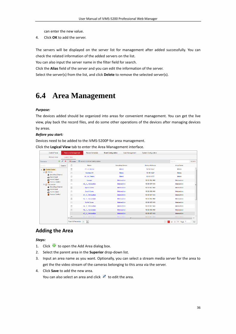
6.4 Area Management
Purpose:
The devices added should be organized into areas for convenient management. You can get the live
view, play back the record files, and do some other operations of the devices after managing devices
by areas.
Before you start:
Devices need to be added to the iVMS-5200P for area management.
Click the Logical View tab to enter the Area Management interface.
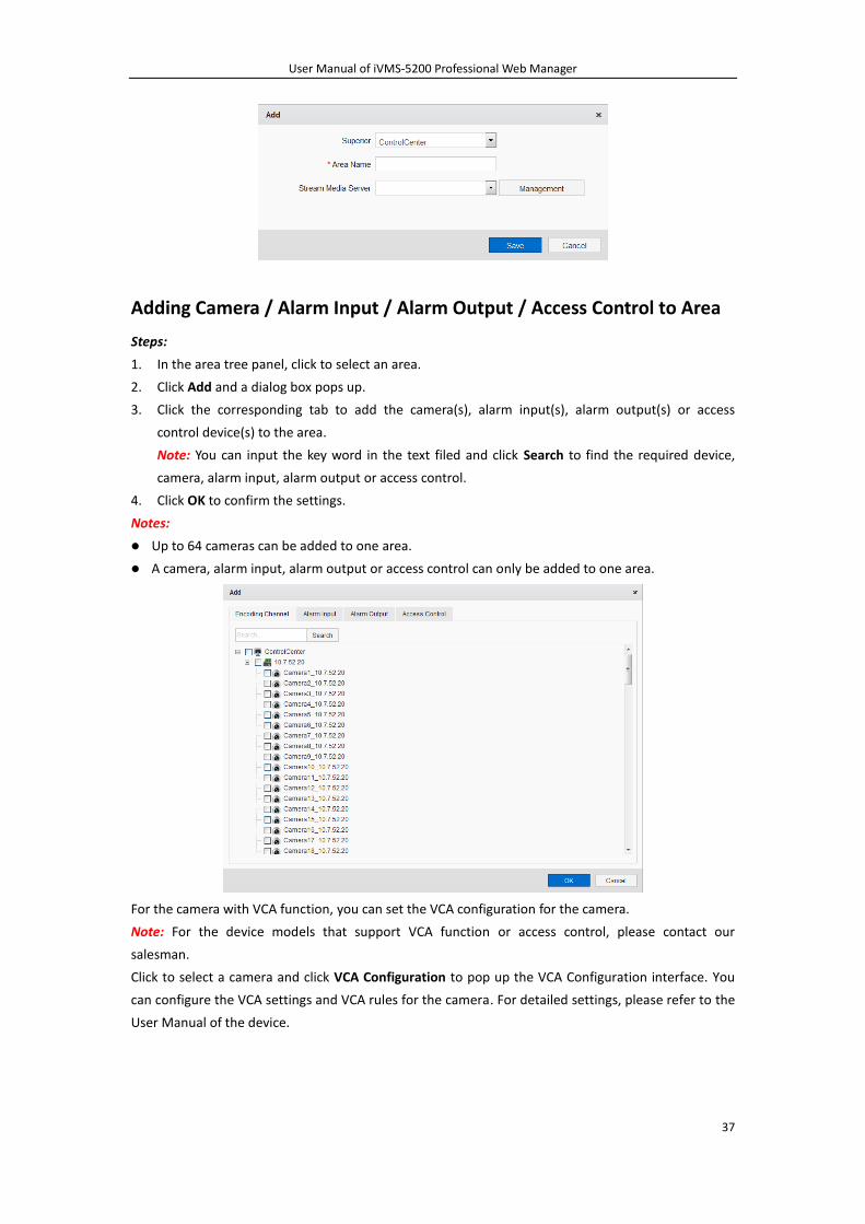
Adding the Area
Steps:
1. Click to open the Add Area dialog box.
2. Select the parent area in the Superior drop-down list.
3. Input an area name as you want. Optionally, you can select a stream media server for the area to
get the the video stream of the cameras belonging to this area via the server.
4. Click Save to add the new area.
You can also select an area and click to edit the area.
User Manual of iVMS-5200 Professional Web Manager
37
Adding Camera / Alarm Input / Alarm Output / Access Control to Area
Steps:
1. In the area tree panel, click to select an area.
2. Click Add and a dialog box pops up.
3. Click the corresponding tab to add the camera(s), alarm input(s), alarm output(s) or access
control device(s) to the area.
Note: You can input the key word in the text filed and click Search to find the required device,
camera, alarm input, alarm output or access control.
4. Click OK to confirm the settings.
Notes:
Up to 64 cameras can be added to one area.
A camera, alarm input, alarm output or access control can only be added to one area.
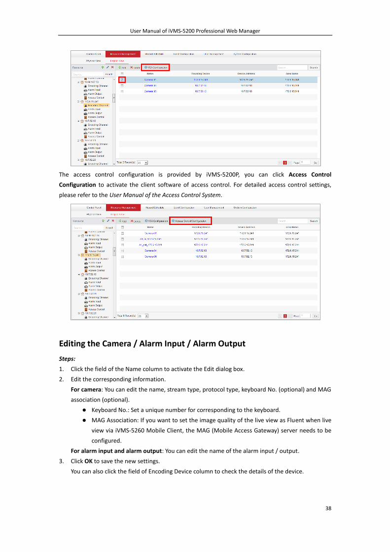
For the camera with VCA function, you can set the VCA configuration for the camera.
Note: For the device models that support VCA function or access control, please contact our
salesman.
Click to select a camera and click VCA Configuration to pop up the VCA Configuration interface. You
can configure the VCA settings and VCA rules for the camera. For detailed settings, please refer to the
User Manual of the device.
User Manual of iVMS-5200 Professional Web Manager
38
The access control configuration is provided by iVMS-5200P, you can click Access Control
Configuration to activate the client software of access control. For detailed access control settings,
please refer to the User Manual of the Access Control System.
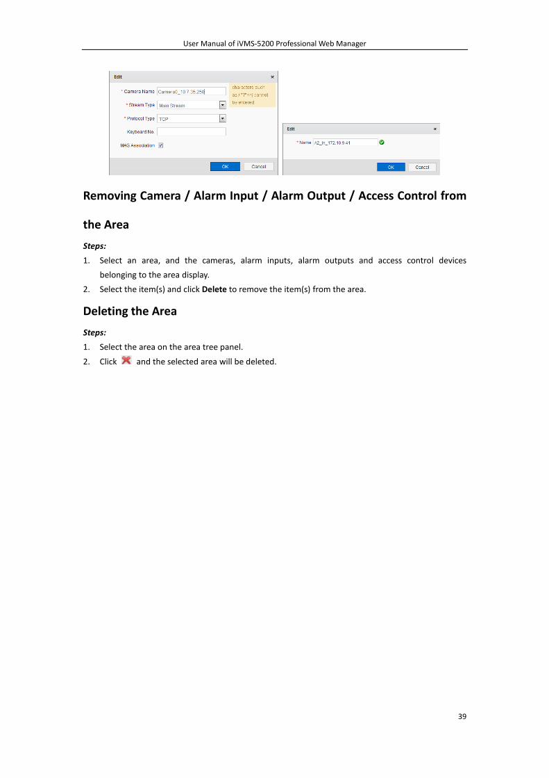
Editing the Camera / Alarm Input / Alarm Output
Steps:
1. Click the field of the Name column to activate the Edit dialog box.
2. Edit the corresponding information.
For camera: You can edit the name, stream type, protocol type, keyboard No. (optional) and MAG
association (optional).
Keyboard No.: Set a unique number for corresponding to the keyboard.
MAG Association: If you want to set the image quality of the live view as Fluent when live
view via iVMS-5260 Mobile Client, the MAG (Mobile Access Gateway) server needs to be
configured.
For alarm input and alarm output: You can edit the name of the alarm input / output.
3. Click OK to save the new settings.
You can also click the field of Encoding Device column to check the details of the device.
User Manual of iVMS-5200 Professional Web Manager
39
Removing Camera / Alarm Input / Alarm Output / Access Control from
the Area
Steps:
1. Select an area, and the cameras, alarm inputs, alarm outputs and access control devices
belonging to the area display.
2. Select the item(s) and click Delete to remove the item(s) from the area.
Deleting the Area
Steps:
1. Select the area on the area tree panel.
2. Click and the selected area will be deleted.
User Manual of iVMS-5200 Professional Web Manager
40
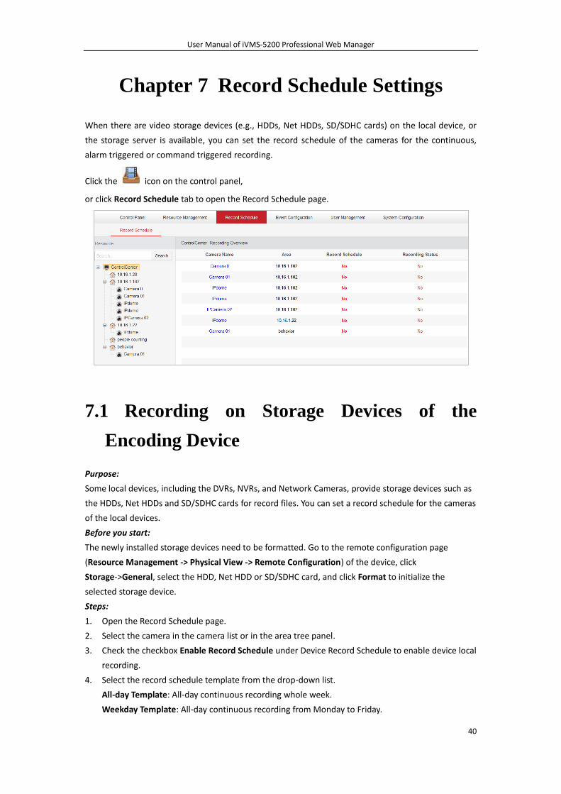
Chapter 7 Record Schedule Settings
When there are video storage devices (e.g., HDDs, Net HDDs, SD/SDHC cards) on the local device, or
the storage server is available, you can set the record schedule of the cameras for the continuous,
alarm triggered or command triggered recording.
Click the icon on the control panel,
or click Record Schedule tab to open the Record Schedule page.
7.1 Recording on Storage Devices of the
Encoding Device
Purpose:
Some local devices, including the DVRs, NVRs, and Network Cameras, provide storage devices such as
the HDDs, Net HDDs and SD/SDHC cards for record files. You can set a record schedule for the cameras
of the local devices.
Before you start:
The newly installed storage devices need to be formatted. Go to the remote configuration page
(Resource Management -> Physical View -> Remote Configuration) of the device, click
Storage->General, select the HDD, Net HDD or SD/SDHC card, and click Format to initialize the
selected storage device.
Steps:
1. Open the Record Schedule page.
2. Select the camera in the camera list or in the area tree panel.
3. Check the checkbox Enable Record Schedule under Device Record Schedule to enable device local
recording.
4. Select the record schedule template from the drop-down list.
All-day Template: All-day continuous recording whole week.
Weekday Template: All-day continuous recording from Monday to Friday.
User Manual of iVMS-5200 Professional Web Manager
41
Weekend Template: All-day continuous recording from Saturday to Sunday.
Recording Template 01-08: You can edit the templates as desired.
If you need to edit or customize the template, see Chapter 7.1.1 Configuring Record Schedule
Template.
5. Optionally, click Copy to to copy the record schedule settings to other cameras.
6. Click Save to save the settings.
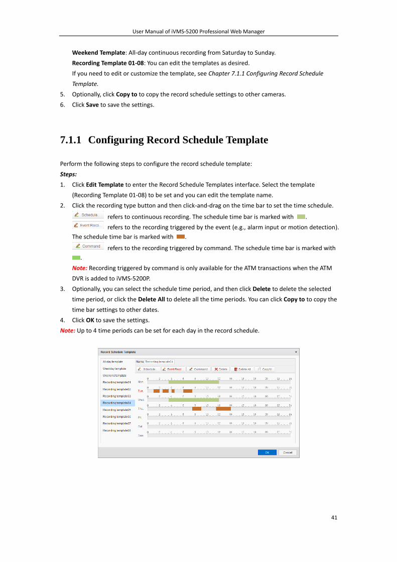
7.1.1 Configuring Record Schedule Template
Perform the following steps to configure the record schedule template:
Steps:
1. Click Edit Template to enter the Record Schedule Templates interface. Select the template
(Recording Template 01-08) to be set and you can edit the template name.
2. Click the recording type button and then click-and-drag on the time bar to set the time schedule.
refers to continuous recording. The schedule time bar is marked with .
refers to the recording triggered by the event (e.g., alarm input or motion detection).
The schedule time bar is marked with .
refers to the recording triggered by command. The schedule time bar is marked with
.
Note: Recording triggered by command is only available for the ATM transactions when the ATM
DVR is added to iVMS-5200P.
3. Optionally, you can select the schedule time period, and then click Delete to delete the selected
time period, or click the Delete All to delete all the time periods. You can click Copy to to copy the
time bar settings to other dates.
4. Click OK to save the settings.
Note: Up to 4 time periods can be set for each day in the record schedule.
User Manual of iVMS-5200 Professional Web Manager
42
7.2 Recording on Storage Server
Purpose:
The storage server performs as a NVR installed on the server. The record files and captured pictures
can be stored in the storage server.
Before you start:
At least one available storage server has been added to the iVMS-5200P. When installing the
iVMS-5200P, check the checkbox Storage Server to enable the installation of Storage Server.
For adding the Storage Server, please refer to Chapter 6.3 Adding the Server.
Steps:
1. Open the Record Schedule page.
2. Select the camera in the camera list or in the area tree panel.
3. Check the checkbox Enable Record Schedule under Storage Server Record Schedule to enable
recording on storage server.
4. Select the record schedule template from the drop-down list.
If you need to edit the template, see Chapter 7.1.1 Configuring Record Schedule Template.
5. Select the storage server from the drop-down list. If you want to add / delete the storage server,
click Management. For detailed configuration, please refer to Chapter 6.3 Adding the Server.
6. Select the stream type for recording from the drop-down list.
Note: For configuration of Storage Server, please refer to Chapter 11.3 How to Allocate Storage
Space for Storage Server.
7. Optionally, you can check the checkbox Obtain Video Stream via Stream Media Server to get the
video stream of the camera via stream media server for recording.
Note: A SMS should be added properly. Please refer to Chapter 6.3 Adding the Server for adding
the SMS.
8. Check the checkbox Enable under Picture Storage to enable uploading the alarm pictures to SS.
Note: The function of uploading alarm pictures to SS should be supported by the device. Please
contact your dealer or our salesman to get the list of the supported devices. The following
configuration should be done to enable this function
1) Set the event configuration via the Web Manager. Please refer to Chapter 8.1 Configuring
Camera Exception Alarm. The Notify Surveillance Center for the VCA picture and Notify
Surveillance Center for the event should be enabled when configuring the alarm settings to
enable uploading the alarm pictures to SS.
2) View the alarm pictures. Please enter the Alarm Center interface of the Control Client to
check the alarm pictures that are uploaded to the SS. For details, please refer to the User
Manual of iVMS-5200 Control Client.
9. Select the storage server from the drop-down list.
10. Optionally, click Copy to to copy the record schedule settings to other cameras.
11. Click Save to save the settings.
User Manual of iVMS-5200 Professional Web Manager
43
Chapter 8 Event Configuration
Purpose:
In iVMS-5200 Web Manager, you can assign linkage actions to the event by setting up a rule. For
example, when motion is detected, an audible warning appears or other linkage actions happen.
The alarm information of the events can be received by the iVMS-5200 Control Client. For detailed
information about checking the alarm information, please refer to the User Manual of iVMS-5200
Control Client.
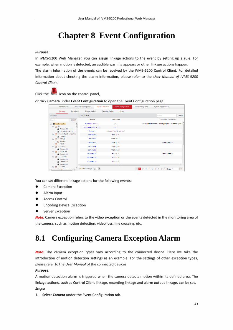
Click the icon on the control panel,
or click Camera under Event Configuration to open the Event Configuration page.
You can set different linkage actions for the following events:
Camera Exception
Alarm Input
Access Control
Encoding Device Exception
Server Exception
Note: Camera exception refers to the video exception or the events detected in the monitoring area of
the camera, such as motion detection, video loss, line crossing, etc.
8.1 Configuring Camera Exception Alarm
Note: The camera exception types vary according to the connected device. Here we take the
introduction of motion detection settings as an example. For the settings of other exception types,
please refer to the User Manual of the connected devices.
Purpose:
A motion detection alarm is triggered when the camera detects motion within its defined area. The
linkage actions, such as Control Client linkage, recording linkage and alarm output linkage, can be set.
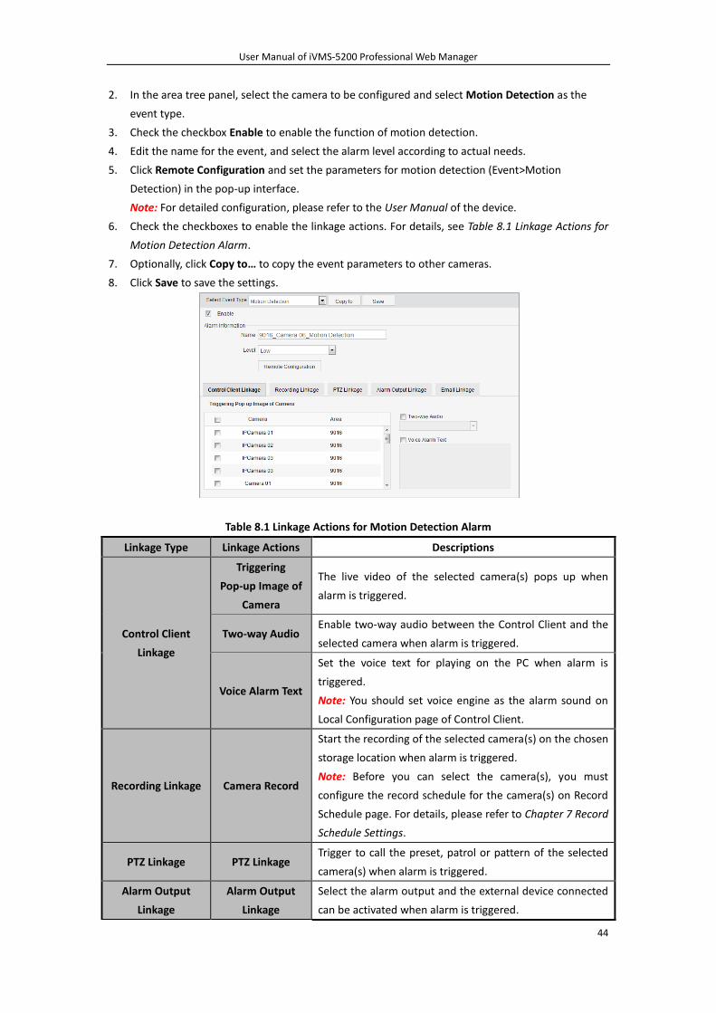
Steps:
1. Select Camera under the Event Configuration tab.
User Manual of iVMS-5200 Professional Web Manager
44
2. In the area tree panel, select the camera to be configured and select Motion Detection as the
event type.
3. Check the checkbox Enable to enable the function of motion detection.
4. Edit the name for the event, and select the alarm level according to actual needs.
5. Click Remote Configuration and set the parameters for motion detection (Event>Motion
Detection) in the pop-up interface.
Note: For detailed configuration, please refer to the User Manual of the device.
6. Check the checkboxes to enable the linkage actions. For details, see Table 8.1 Linkage Actions for
Motion Detection Alarm.
7. Optionally, click Copy to… to copy the event parameters to other cameras.
8. Click Save to save the settings.
Table 8.1 Linkage Actions for Motion Detection Alarm
Linkage Type Linkage Actions Descriptions
Control Client
Linkage
Triggering
Pop-up Image of
Camera
The live video of the selected camera(s) pops up when
alarm is triggered.
Two-way Audio Enable two-way audio between the Control Client and the
selected camera when alarm is triggered.
Voice Alarm Text
Set the voice text for playing on the PC when alarm is
triggered.
Note: You should set voice engine as the alarm sound on
Local Configuration page of Control Client.
Recording Linkage Camera Record
Start the recording of the selected camera(s) on the chosen
storage location when alarm is triggered.
Note: Before you can select the camera(s), you must
configure the record schedule for the camera(s) on Record
Schedule page. For details, please refer to Chapter 7 Record
Schedule Settings.
PTZ Linkage PTZ Linkage Trigger to call the preset, patrol or pattern of the selected
camera(s) when alarm is triggered.
Alarm Output
Linkage
Alarm Output
Linkage
Select the alarm output and the external device connected
can be activated when alarm is triggered.
User Manual of iVMS-5200 Professional Web Manager
45
Email Linkage Email Linkage
Send an Email notification of the alarm information to one
or more receivers.
Notes:
Only the users that are configured with email are
available in the pop-up window when you click
Receiver. For configuring users, please refer to
Chapter 9.2 User Management.
You should configure the email settings for the system
in System Configuration page. For details, please refer
to Chapter 10.3 Email Settings.
8.2 Configuring Line Crossing Detection
Note: This chapter is only available for the cameras of Behavior Analysis server. For adding the
Behavior Analysis server, please refer to Chapter 6.2 Adding the Behavior Analysis Server.
Purpose:
This function can be used for detecting people, vehicles and objects crossing a pre-defined area.
The line crossing direction can be set as bidirectional, from left to right or from right to left. And
a series of linkage method will be triggered if any object is detected.
Steps:
1. Select Camera under the Event Configuration tab.
2. In the area tree panel, select the camera of Behavior Analysis server to be configured and select
Line Crossing Detection as the event type.
3. Check the checkbox Enable to enable the function of motion detection.
4. Edit the name for the event, and select the alarm level according to actual needs.
5. Click Remote Configuration and set the parameters for line crossing detection (Event>Line
Crossing Detection) in the pop-up interface.
1) Check the Enable Line Crossing Detection checkbox.
2) Select the virtual line ID and up to 4 lines can be configured.
3) And you can select the directions as A<->B, A ->B, and B->A.
A<->B: Only the arrow on the B side shows; when an object going across the plane
with both direction can be detected and alarms are triggered.
A->B: Only the object crossing the configured line from the A side to the B side can be
detected.
B->A: Only the object crossing the configured line from the B side to the A side can be
detected.
4) Click and then draw a line on the preview image. You can click and then drag
the configured line to adjust its position. You can also click or to delete the line.
5) You can repeat step 2)-4) to set other virtual lines.
6) Set the sensitivity [1~100].
User Manual of iVMS-5200 Professional Web Manager
46
7) Set the arming schedule and linkage method (notify surveillance center and trigger
camera).
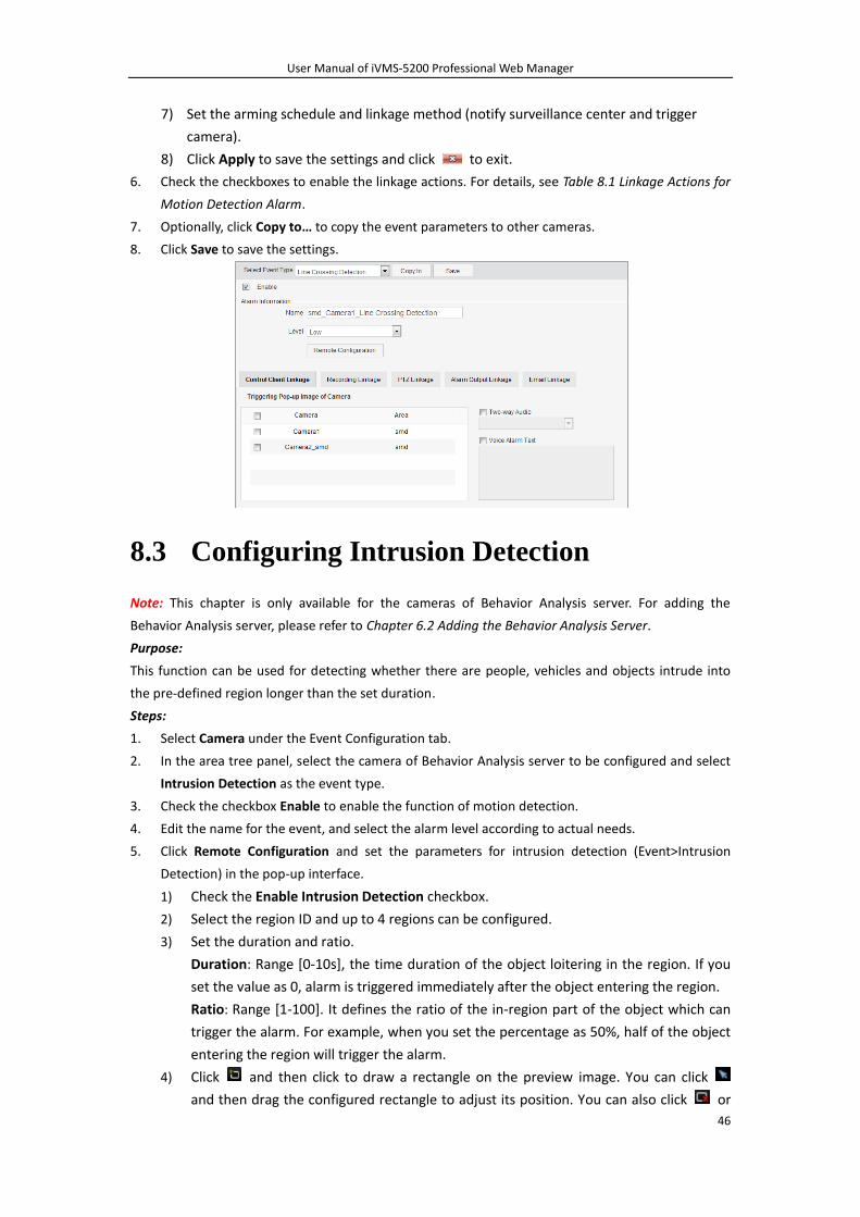
8) Click Apply to save the settings and click to exit.
6. Check the checkboxes to enable the linkage actions. For details, see Table 8.1 Linkage Actions for
Motion Detection Alarm.
7. Optionally, click Copy to… to copy the event parameters to other cameras.
8. Click Save to save the settings.
8.3 Configuring Intrusion Detection
Note: This chapter is only available for the cameras of Behavior Analysis server. For adding the
Behavior Analysis server, please refer to Chapter 6.2 Adding the Behavior Analysis Server.
Purpose:
This function can be used for detecting whether there are people, vehicles and objects intrude into
the pre-defined region longer than the set duration.
Steps:
1. Select Camera under the Event Configuration tab.
2. In the area tree panel, select the camera of Behavior Analysis server to be configured and select
Intrusion Detection as the event type.
3. Check the checkbox Enable to enable the function of motion detection.
4. Edit the name for the event, and select the alarm level according to actual needs.
5. Click Remote Configuration and set the parameters for intrusion detection (Event>Intrusion
Detection) in the pop-up interface.
1) Check the Enable Intrusion Detection checkbox.
2) Select the region ID and up to 4 regions can be configured.
3) Set the duration and ratio.
Duration: Range [0-10s], the time duration of the object loitering in the region. If you
set the value as 0, alarm is triggered immediately after the object entering the region.
Ratio: Range [1-100]. It defines the ratio of the in-region part of the object which can
trigger the alarm. For example, when you set the percentage as 50%, half of the object
entering the region will trigger the alarm.
4) Click and then click to draw a rectangle on the preview image. You can click
and then drag the configured rectangle to adjust its position. You can also click or
User Manual of iVMS-5200 Professional Web Manager
47
to delete the rectangle.
5) You can repeat step 2)-4) to set other regions.
6) Set the sensitivity [1~100].
7) Set the arming schedule and linkage method (notify surveillance center and trigger
camera).
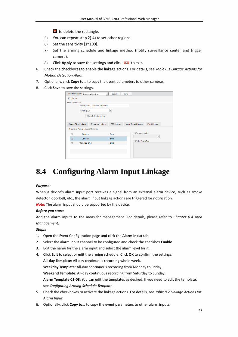
8) Click Apply to save the settings and click to exit.
6. Check the checkboxes to enable the linkage actions. For details, see Table 8.1 Linkage Actions for
Motion Detection Alarm.
7. Optionally, click Copy to… to copy the event parameters to other cameras.
8. Click Save to save the settings.
8.4 Configuring Alarm Input Linkage
Purpose:
When a device's alarm input port receives a signal from an external alarm device, such as smoke
detector, doorbell, etc., the alarm input linkage actions are triggered for notification.
Note: The alarm input should be supported by the device.
Before you start:
Add the alarm inputs to the areas for management. For details, please refer to Chapter 6.4 Area
Management.
Steps:
1. Open the Event Configuration page and click the Alarm Input tab.
2. Select the alarm input channel to be configured and check the checkbox Enable.
3. Edit the name for the alarm input and select the alarm level for it.
4. Click Edit to select or edit the arming schedule. Click OK to confirm the settings.
All-day Template: All-day continuous recording whole week.
Weekday Template: All-day continuous recording from Monday to Friday.
Weekend Template: All-day continuous recording from Saturday to Sunday.
Alarm Template 01-08: You can edit the templates as desired. If you need to edit the template,
see Configuring Arming Schedule Template.
5. Check the checkboxes to activate the linkage actions. For details, see Table 8.2 Linkage Actions for
Alarm Input.
6. Optionally, click Copy to… to copy the event parameters to other alarm inputs.
User Manual of iVMS-5200 Professional Web Manager
48
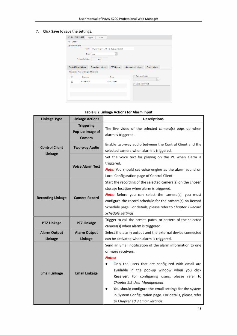
7. Click Save to save the settings.
Table 8.2 Linkage Actions for Alarm Input
Linkage Type Linkage Actions Descriptions
Control Client
Linkage
Triggering
Pop-up Image of
Camera
The live video of the selected camera(s) pops up when
alarm is triggered.
Two-way Audio Enable two-way audio between the Control Client and the
selected camera when alarm is triggered.
Voice Alarm Text
Set the voice text for playing on the PC when alarm is
triggered.
Note: You should set voice engine as the alarm sound on
Local Configuration page of Control Client.
Recording Linkage Camera Record
Start the recording of the selected camera(s) on the chosen
storage location when alarm is triggered.
Note: Before you can select the camera(s), you must
configure the record schedule for the camera(s) on Record
Schedule page. For details, please refer to Chapter 7 Record
Schedule Settings.
PTZ Linkage PTZ Linkage Trigger to call the preset, patrol or pattern of the selected
camera(s) when alarm is triggered.
Alarm Output
Linkage
Alarm Output
Linkage
Select the alarm output and the external device connected
can be activated when alarm is triggered.
Email Linkage Email Linkage
Send an Email notification of the alarm information to one
or more receivers.
Notes:
Only the users that are configured with email are
available in the pop-up window when you click
Receiver. For configuring users, please refer to
Chapter 9.2 User Management.
You should configure the email settings for the system
in System Configuration page. For details, please refer
to Chapter 10.3 Email Settings.
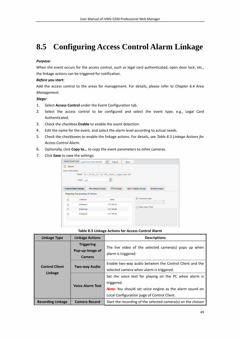
User Manual of iVMS-5200 Professional Web Manager
49
8.5 Configuring Access Control Alarm Linkage
Purpose:
When the event occurs for the access control, such as legal card authenticated, open door lock, etc.,
the linkage actions can be triggered for notification.
Before you start:
Add the access control to the areas for management. For details, please refer to Chapter 6.4 Area
Management.
Steps:
1. Select Access Control under the Event Configuration tab.
2. Select the access control to be configured and select the event type, e.g., Legal Card
Authenticated.
3. Check the checkbox Enable to enable the event detection.
4. Edit the name for the event, and select the alarm level according to actual needs.
5. Check the checkboxes to enable the linkage actions. For details, see Table 8.3 Linkage Actions for
Access Control Alarm.
6. Optionally, click Copy to… to copy the event parameters to other cameras.
7. Click Save to save the settings.
Table 8.3 Linkage Actions for Access Control Alarm
Linkage Type Linkage Actions Descriptions
Control Client
Linkage
Triggering
Pop-up Image of
Camera
The live video of the selected camera(s) pops up when
alarm is triggered.
Two-way Audio Enable two-way audio between the Control Client and the
selected camera when alarm is triggered.
Voice Alarm Text
Set the voice text for playing on the PC when alarm is
triggered.
Note: You should set voice engine as the alarm sound on
Local Configuration page of Control Client.
Recording Linkage Camera Record Start the recording of the selected camera(s) on the chosen
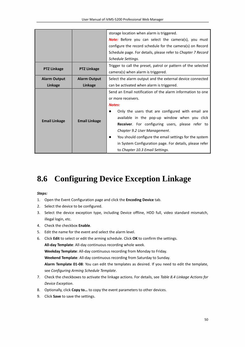
User Manual of iVMS-5200 Professional Web Manager
50
storage location when alarm is triggered.
Note: Before you can select the camera(s), you must
configure the record schedule for the camera(s) on Record
Schedule page. For details, please refer to Chapter 7 Record
Schedule Settings.
PTZ Linkage PTZ Linkage Trigger to call the preset, patrol or pattern of the selected
camera(s) when alarm is triggered.
Alarm Output
Linkage
Alarm Output
Linkage
Select the alarm output and the external device connected
can be activated when alarm is triggered.
Email Linkage Email Linkage
Send an Email notification of the alarm information to one
or more receivers.
Notes:
Only the users that are configured with email are
available in the pop-up window when you click
Receiver. For configuring users, please refer to
Chapter 9.2 User Management.
You should configure the email settings for the system
in System Configuration page. For details, please refer
to Chapter 10.3 Email Settings.
8.6 Configuring Device Exception Linkage
Steps:
1. Open the Event Configuration page and click the Encoding Device tab.
2. Select the device to be configured.
3. Select the device exception type, including Device offline, HDD full, video standard mismatch,
illegal login, etc.
4. Check the checkbox Enable.
5. Edit the name for the event and select the alarm level.
6. Click Edit to select or edit the arming schedule. Click OK to confirm the settings.
All-day Template: All-day continuous recording whole week.
Weekday Template: All-day continuous recording from Monday to Friday.
Weekend Template: All-day continuous recording from Saturday to Sunday.
Alarm Template 01-08: You can edit the templates as desired. If you need to edit the template,
see Configuring Arming Schedule Template.
7. Check the checkboxes to activate the linkage actions. For details, see Table 8.4 Linkage Actions for
Device Exception.
8. Optionally, click Copy to… to copy the event parameters to other devices.
9. Click Save to save the settings.
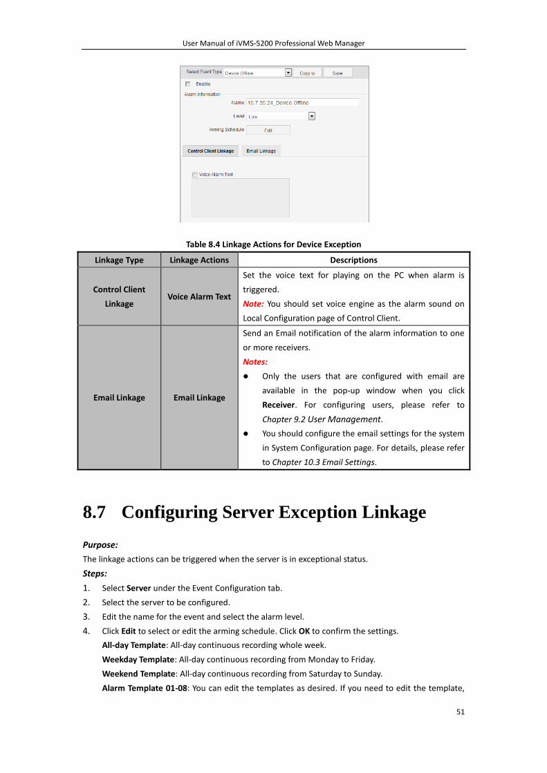
User Manual of iVMS-5200 Professional Web Manager
51
Table 8.4 Linkage Actions for Device Exception
Linkage Type Linkage Actions Descriptions
Control Client
Linkage Voice Alarm Text
Set the voice text for playing on the PC when alarm is
triggered.
Note: You should set voice engine as the alarm sound on
Local Configuration page of Control Client.
Email Linkage Email Linkage
Send an Email notification of the alarm information to one
or more receivers.
Notes:
Only the users that are configured with email are
available in the pop-up window when you click
Receiver. For configuring users, please refer to
Chapter 9.2 User Management.
You should configure the email settings for the system
in System Configuration page. For details, please refer
to Chapter 10.3 Email Settings.
8.7 Configuring Server Exception Linkage
Purpose:
The linkage actions can be triggered when the server is in exceptional status.
Steps:
1. Select Server under the Event Configuration tab.
2. Select the server to be configured.
3. Edit the name for the event and select the alarm level.
4. Click Edit to select or edit the arming schedule. Click OK to confirm the settings.
All-day Template: All-day continuous recording whole week.
Weekday Template: All-day continuous recording from Monday to Friday.
Weekend Template: All-day continuous recording from Saturday to Sunday.
Alarm Template 01-08: You can edit the templates as desired. If you need to edit the template,
User Manual of iVMS-5200 Professional Web Manager
52
see Configuring Arming Schedule Template.
5. Check the checkboxes to activate the linkage actions. For details, see Table 8.5 Linkage Actions
for Device Exception.
6. Optionally, click Copy to… to copy the event parameters to other servers.
7. Click Save to save the settings.
Table 8.5 Linkage Actions for Server Exception
Linkage Type Linkage Actions Descriptions
Control Client
Linkage Voice Alarm Text
Set the voice text for playing on the PC when alarm is
triggered.
Note: You should set voice engine as the alarm sound on
Local Configuration page of Control Client.
Email Linkage Email Linkage
Send an Email notification of the alarm information to one
or more receivers.
Notes:
Only the users that are configured with email are
available in the pop-up window when you click
Receiver. For configuring users, please refer to
Chapter 9.2 User Management.
You should configure the email settings for the system
in System Configuration page. For details, please refer
to Chapter 10.3 Email Settings.
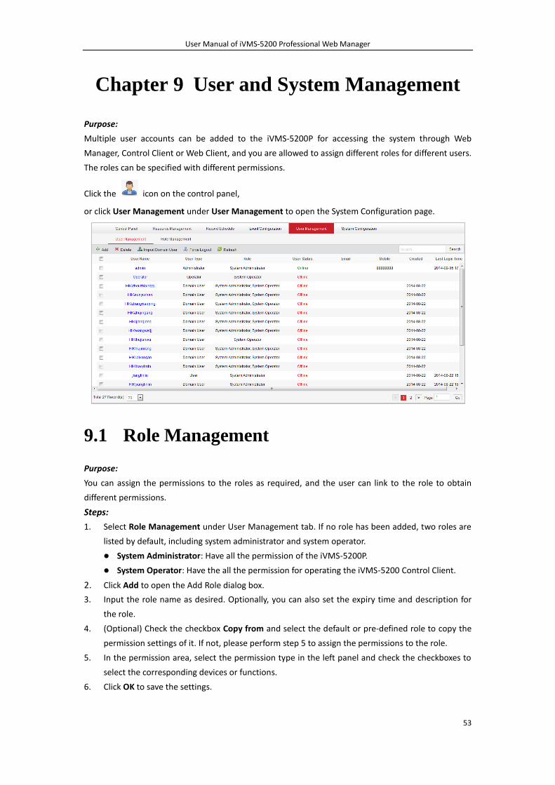
User Manual of iVMS-5200 Professional Web Manager
53
Chapter 9 User and System Management
Purpose:
Multiple user accounts can be added to the iVMS-5200P for accessing the system through Web
Manager, Control Client or Web Client, and you are allowed to assign different roles for different users.
The roles can be specified with different permissions.
Click the icon on the control panel,
or click User Management under User Management to open the System Configuration page.
9.1 Role Management
Purpose:
You can assign the permissions to the roles as required, and the user can link to the role to obtain
different permissions.
Steps:
1. Select Role Management under User Management tab. If no role has been added, two roles are
listed by default, including system administrator and system operator.
System Administrator: Have all the permission of the iVMS-5200P.
System Operator: Have the all the permission for operating the iVMS-5200 Control Client.
2. Click Add to open the Add Role dialog box.
3. Input the role name as desired. Optionally, you can also set the expiry time and description for
the role.
4. (Optional) Check the checkbox Copy from and select the default or pre-defined role to copy the
permission settings of it. If not, please perform step 5 to assign the permissions to the role.
5. In the permission area, select the permission type in the left panel and check the checkboxes to
select the corresponding devices or functions.
6. Click OK to save the settings.
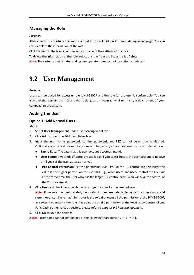
User Manual of iVMS-5200 Professional Web Manager
54
Managing the Role
Purpose:
After created successfully, the role is added to the role list on the Role Management page. You can
edit or delete the information of the roles.
Click the field in the Name column and you can edit the settings of the role.
To delete the information of the role, select the role from the list, and click Delete.
Note: The system administrator and system operator roles cannot be edited or deleted.
9.2 User Management
Purpose:
Users can be added for accessing the iVMS-5200P and the role for the user is configurable. You can
also add the domain users (users that belong to an organizational unit, e.g., a department of your
company) to the system.
Adding the User
Option 1: Add Normal Users Steps:
1. Select User Management under User Management tab.
2. Click Add to open the Add User dialog box.
3. Input the user name, password, confirm password, and PTZ control permission as desired.
Optionally, you can set the mobile phone number, email, expiry date, user status and description.
Expiry Date: The date that this user account becomes invalid.
User Status: Two kinds of status are available. If you select freeze, the user account is inactive
until you set the user status as normal.
PTZ Control Permission: Set the permission level (1~100) for PTZ control and the larger the
value is, the higher permission the user has. E.g., when user1 and user2 control the PTZ unit
at the same time, the user who has the larger PTZ control permission will take the control of
the PTZ movement.
4. Click Next and check the checkboxes to assign the roles for the created user.
Note: If no role has been added, two default roles are selectable: system administrator and
system operator. System administrator is the role that owns all the permission of the iVMS-5200P,
and system operator is the role that owns the all the permission of the iVMS-5200 Control Client.
For creating other roles as desired, please refer to Chapter 9.1 Role Management.
5. Click OK to save the settings.
Note: A user name cannot contain any of the following characters: / \ : * ? “ < > |.
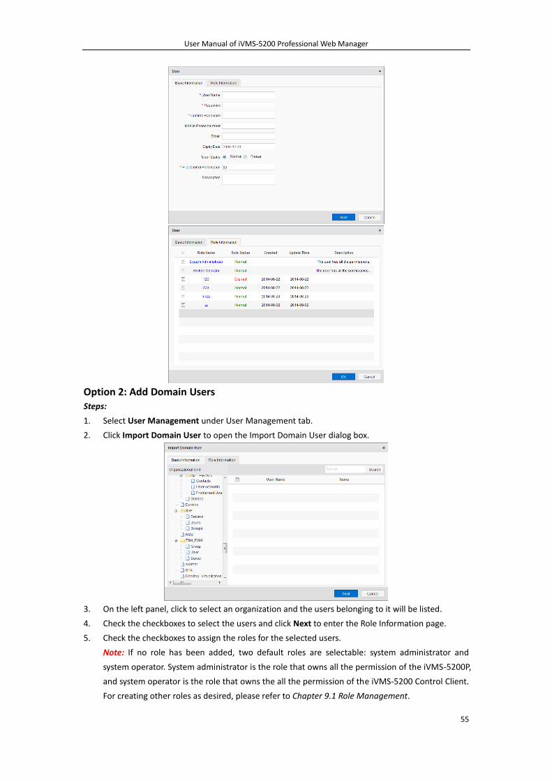
User Manual of iVMS-5200 Professional Web Manager
55
Option 2: Add Domain Users Steps:
1. Select User Management under User Management tab.
2. Click Import Domain User to open the Import Domain User dialog box.
3. On the left panel, click to select an organization and the users belonging to it will be listed.
4. Check the checkboxes to select the users and click Next to enter the Role Information page.
5. Check the checkboxes to assign the roles for the selected users.
Note: If no role has been added, two default roles are selectable: system administrator and
system operator. System administrator is the role that owns all the permission of the iVMS-5200P,
and system operator is the role that owns the all the permission of the iVMS-5200 Control Client.
For creating other roles as desired, please refer to Chapter 9.1 Role Management.
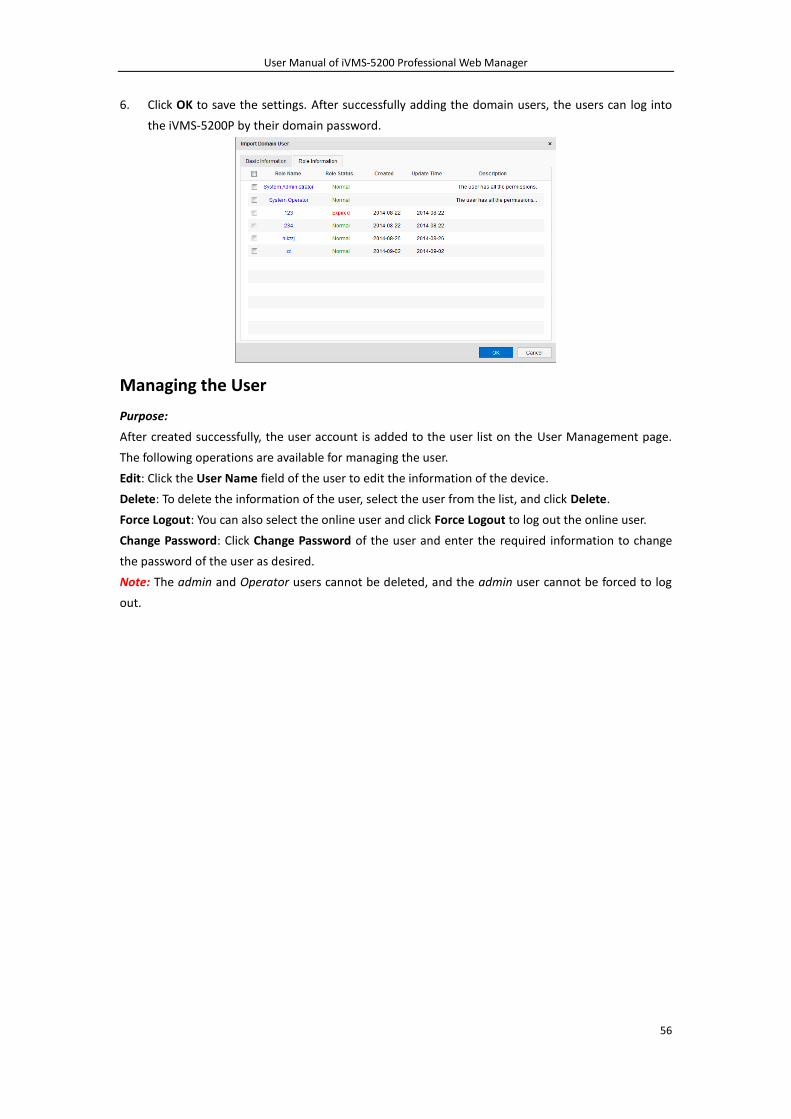
User Manual of iVMS-5200 Professional Web Manager
56
6. Click OK to save the settings. After successfully adding the domain users, the users can log into
the iVMS-5200P by their domain password.
Managing the User
Purpose:
After created successfully, the user account is added to the user list on the User Management page.
The following operations are available for managing the user.
Edit: Click the User Name field of the user to edit the information of the device.
Delete: To delete the information of the user, select the user from the list, and click Delete.
Force Logout: You can also select the online user and click Force Logout to log out the online user.
Change Password: Click Change Password of the user and enter the required information to change
the password of the user as desired.
Note: The admin and Operator users cannot be deleted, and the admin user cannot be forced to log
out.
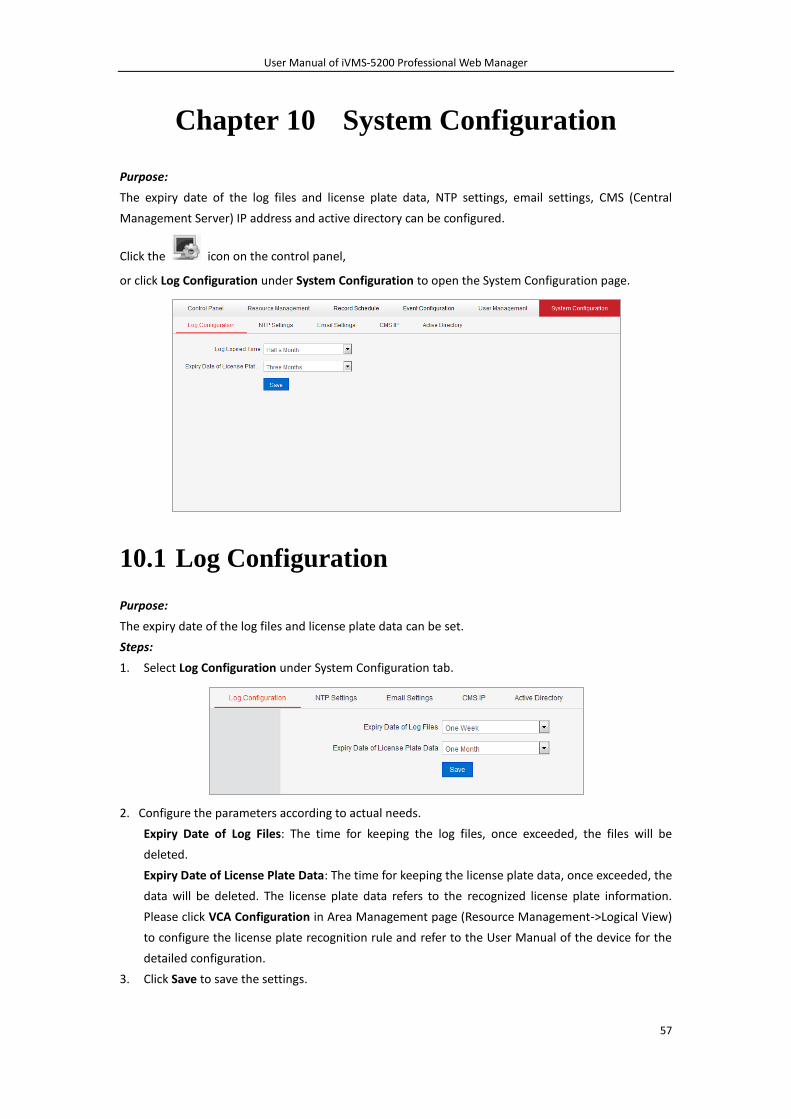
User Manual of iVMS-5200 Professional Web Manager
57
Chapter 10 System Configuration
Purpose:
The expiry date of the log files and license plate data, NTP settings, email settings, CMS (Central
Management Server) IP address and active directory can be configured.
Click the icon on the control panel,
or click Log Configuration under System Configuration to open the System Configuration page.
10.1 Log Configuration
Purpose:
The expiry date of the log files and license plate data can be set.
Steps:
1. Select Log Configuration under System Configuration tab.
2. Configure the parameters according to actual needs.
Expiry Date of Log Files: The time for keeping the log files, once exceeded, the files will be
deleted.
Expiry Date of License Plate Data: The time for keeping the license plate data, once exceeded, the
data will be deleted. The license plate data refers to the recognized license plate information.
Please click VCA Configuration in Area Management page (Resource Management->Logical View)
to configure the license plate recognition rule and refer to the User Manual of the device for the
detailed configuration.
3. Click Save to save the settings.
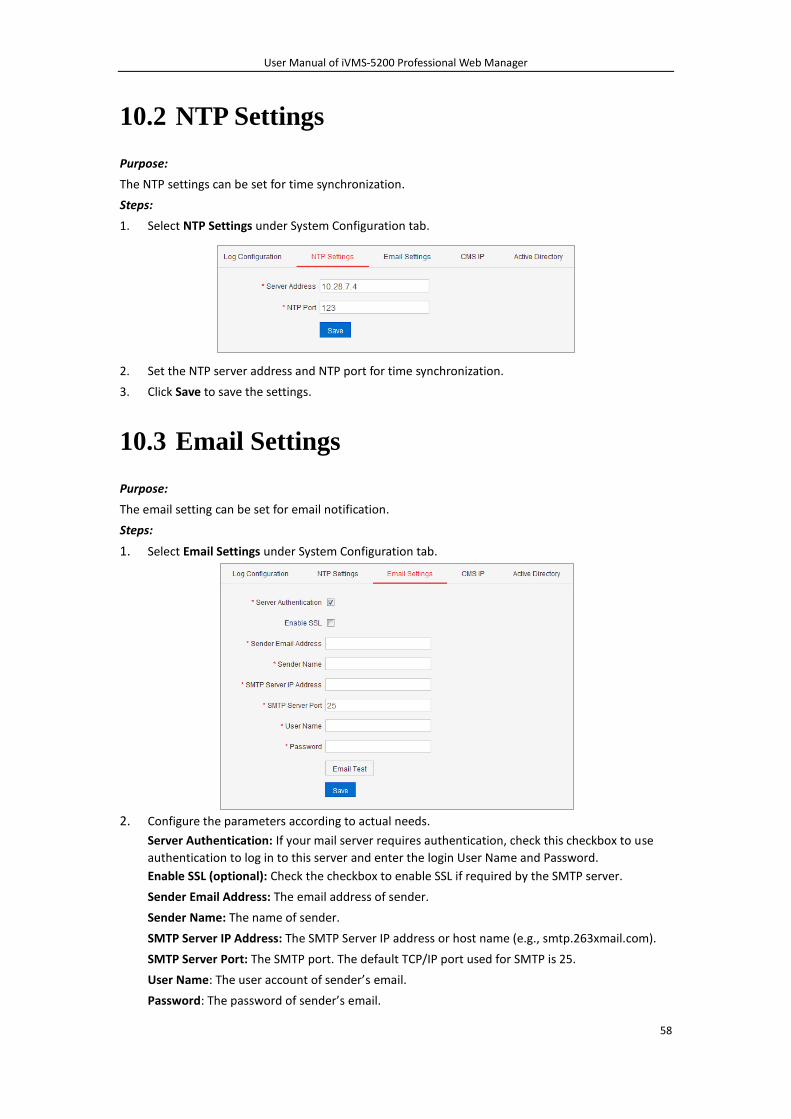
User Manual of iVMS-5200 Professional Web Manager
58
10.2 NTP Settings
Purpose:
The NTP settings can be set for time synchronization.
Steps:
1. Select NTP Settings under System Configuration tab.
2. Set the NTP server address and NTP port for time synchronization.
3. Click Save to save the settings.
10.3 Email Settings
Purpose:
The email setting can be set for email notification.
Steps:
1. Select Email Settings under System Configuration tab.
2. Configure the parameters according to actual needs.
Server Authentication: If your mail server requires authentication, check this checkbox to use
authentication to log in to this server and enter the login User Name and Password.
Enable SSL (optional): Check the checkbox to enable SSL if required by the SMTP server.
Sender Email Address: The email address of sender.
Sender Name: The name of sender.
SMTP Server IP Address: The SMTP Server IP address or host name (e.g., smtp.263xmail.com).
SMTP Server Port: The SMTP port. The default TCP/IP port used for SMTP is 25.
User Name: The user account of sender’s email.
Password: The password of sender’s email.
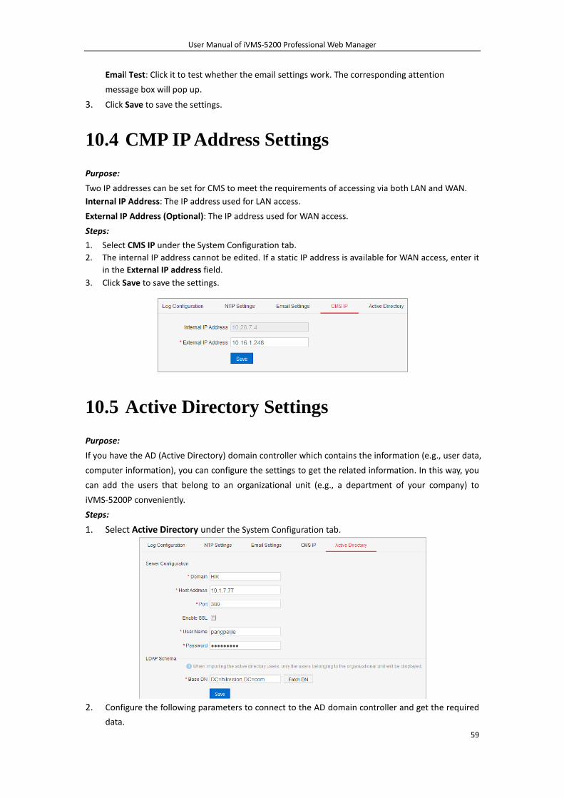
User Manual of iVMS-5200 Professional Web Manager
59
Email Test: Click it to test whether the email settings work. The corresponding attention
message box will pop up.
3. Click Save to save the settings.
10.4 CMP IP Address Settings
Purpose:
Two IP addresses can be set for CMS to meet the requirements of accessing via both LAN and WAN.
Internal IP Address: The IP address used for LAN access.
External IP Address (Optional): The IP address used for WAN access.
Steps:
1. Select CMS IP under the System Configuration tab.
2. The internal IP address cannot be edited. If a static IP address is available for WAN access, enter it
in the External IP address field.
3. Click Save to save the settings.
10.5 Active Directory Settings
Purpose:
If you have the AD (Active Directory) domain controller which contains the information (e.g., user data,
computer information), you can configure the settings to get the related information. In this way, you
can add the users that belong to an organizational unit (e.g., a department of your company) to
iVMS-5200P conveniently.
Steps:
1. Select Active Directory under the System Configuration tab.
2. Configure the following parameters to connect to the AD domain controller and get the required
data.
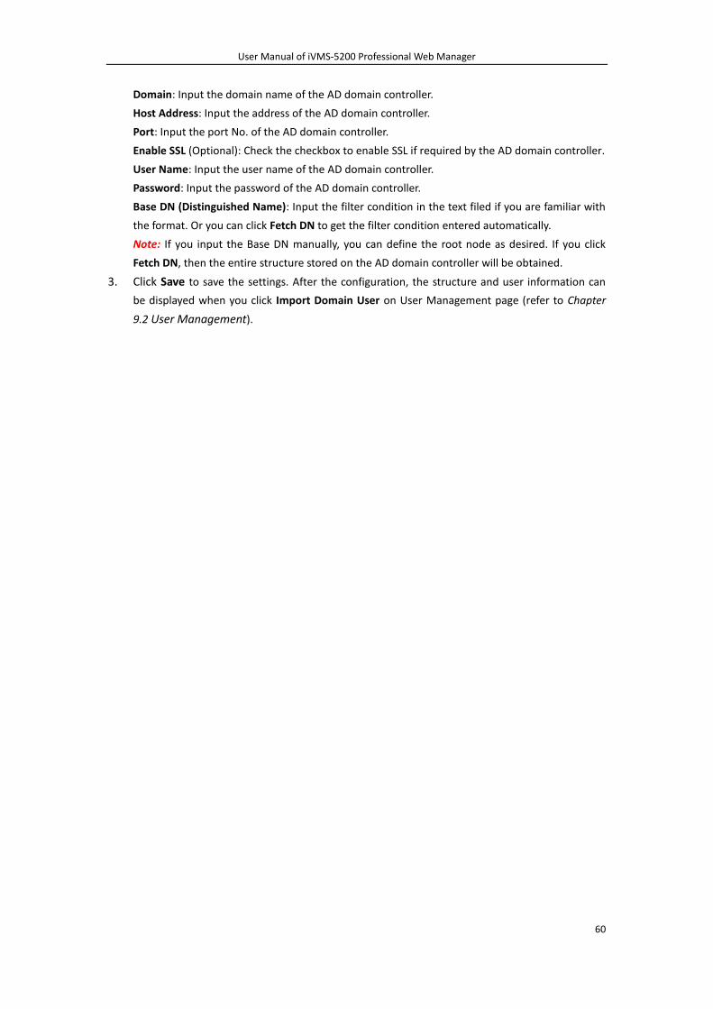
User Manual of iVMS-5200 Professional Web Manager
60
Domain: Input the domain name of the AD domain controller.
Host Address: Input the address of the AD domain controller.
Port: Input the port No. of the AD domain controller.
Enable SSL (Optional): Check the checkbox to enable SSL if required by the AD domain controller.
User Name: Input the user name of the AD domain controller.
Password: Input the password of the AD domain controller.
Base DN (Distinguished Name): Input the filter condition in the text filed if you are familiar with
the format. Or you can click Fetch DN to get the filter condition entered automatically.
Note: If you input the Base DN manually, you can define the root node as desired. If you click
Fetch DN, then the entire structure stored on the AD domain controller will be obtained.
3. Click Save to save the settings. After the configuration, the structure and user information can
be displayed when you click Import Domain User on User Management page (refer to Chapter
9.2 User Management).
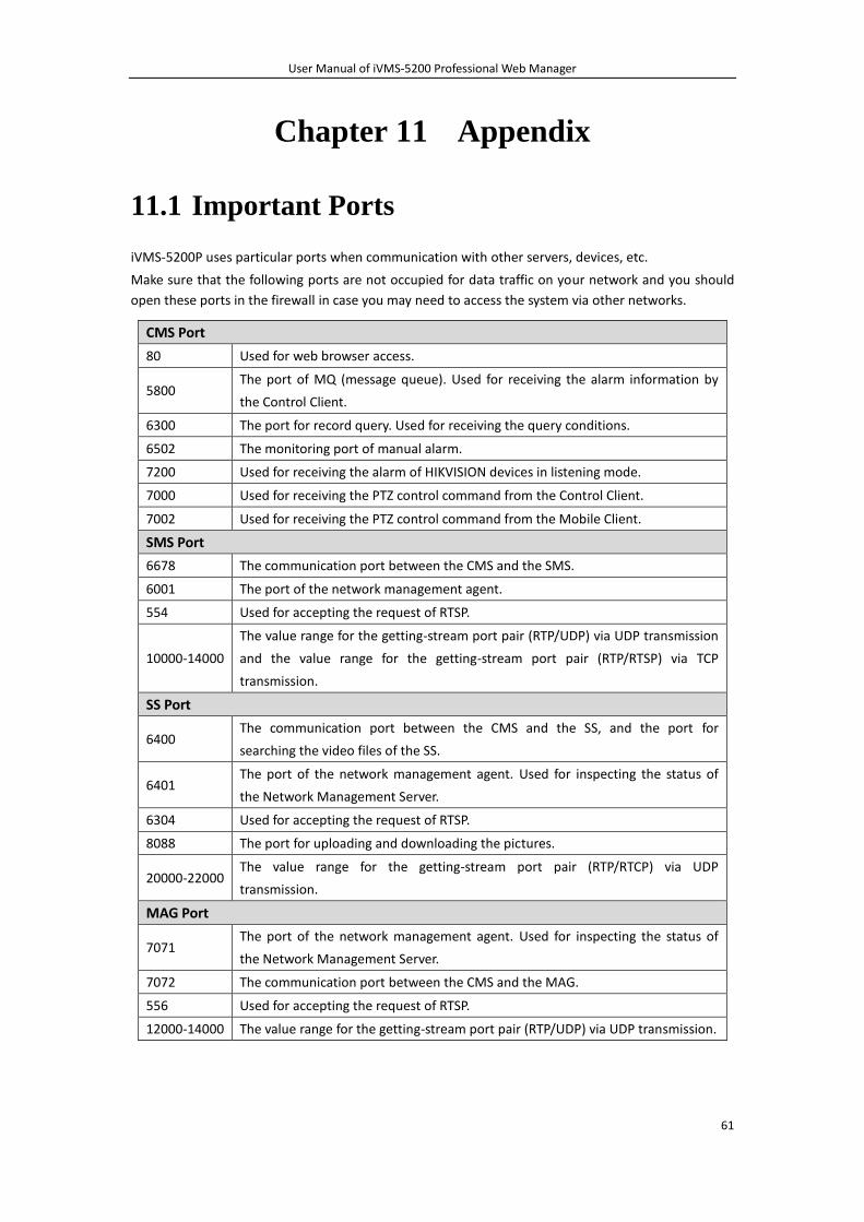
User Manual of iVMS-5200 Professional Web Manager
61
Chapter 11 Appendix
11.1 Important Ports
iVMS-5200P uses particular ports when communication with other servers, devices, etc.
Make sure that the following ports are not occupied for data traffic on your network and you should
open these ports in the firewall in case you may need to access the system via other networks.
CMS Port
80 Used for web browser access.
5800 The port of MQ (message queue). Used for receiving the alarm information by
the Control Client.
6300 The port for record query. Used for receiving the query conditions.
6502 The monitoring port of manual alarm.
7200 Used for receiving the alarm of HIKVISION devices in listening mode.
7000 Used for receiving the PTZ control command from the Control Client.
7002 Used for receiving the PTZ control command from the Mobile Client.
SMS Port
6678 The communication port between the CMS and the SMS.
6001 The port of the network management agent.
554 Used for accepting the request of RTSP.
10000-14000
The value range for the getting-stream port pair (RTP/UDP) via UDP transmission
and the value range for the getting-stream port pair (RTP/RTSP) via TCP
transmission.
SS Port
6400 The communication port between the CMS and the SS, and the port for
searching the video files of the SS.
6401 The port of the network management agent. Used for inspecting the status of
the Network Management Server.
6304 Used for accepting the request of RTSP.
8088 The port for uploading and downloading the pictures.
20000-22000 The value range for the getting-stream port pair (RTP/RTCP) via UDP
transmission.
MAG Port
7071 The port of the network management agent. Used for inspecting the status of
the Network Management Server.
7072 The communication port between the CMS and the MAG.
556 Used for accepting the request of RTSP.
12000-14000 The value range for the getting-stream port pair (RTP/UDP) via UDP transmission.
User Manual of iVMS-5200 Professional Web Manager
62
11.2 FAQ
Q: Why does the CMS fail to start?
A: a) The memory of your PC or server may be insufficient for running the CMS properly. Please
perform the steps below:
Steps:
1. Please make sure that the running environment of the PC or server meets the
recommended configuration (refer to Chapter 3.1 Installing the Server Modules) and close
other services before running the CMS.
2. Then run the Watchdog as administrator and check the status of CMS. The status changes
to Running which means the CMS is working properly.
3. Then you can log into the iVMS-5200P via Web Manager by inputting http://IP address of
CMS /manager in the address bar of your web browser.
Example: Input http://172.6.21.55/manager in the address bar to access the iVMS-5200P.
b) The port 80 of your PC or server installing the CMS may be occupied by other service. Please
check whether the port 80 (you can input netstat -ano|findstr "80" in the console) is available. If
it is occupied:
Please change the port of the service to other value since the port 80 should be used when
running the CMS. Please consult your IT system administrator if in doubt about how to
changing the port No..
Or please perform the following steps to change the port of CMS to other available value.
Steps:
1. Shut down all iVMS-5200P modules and exit the iVMS-5200 Service Watchdog.
2. Go to the installation directory of the CMS, and open the server.xml file (by default, the
directory is: C:\Program Files\iVMS-5200 Professional\iVMS-5200
CMS\webserver\Tomcat\conf).
3. Find the content Connector port="80" protocol="HTTP/1.1" in the file and change the 80
to other value (e.g., 85) that is not occupied by other service.
4. Run the Watchdog as administrator and check the status of CMS. The status changes to
Running which means the CMS is working properly.
5. Then you can log into the iVMS-5200P via Web Manager by inputting http://IP address of
CMS:new port in the address bar of your web browser.
Example: Input http://172.6.21.55:85 in the address bar to access the iVMS-5200P.
Q: Why does the status of the Storage Server on the Watchdog show as Unusable
after successfully allocating the storage space for the Storage Server? A: The Storage Server should be installed on the 64-bit PC or server. Please make sure that the PC or
server that running the Storage Server is 64-bit operating system.
Q: Why does the downloading of the Watchdog log files fail? A: The port used for downloading the Watchdog log files may be occupied by other service. Please
follow the steps below.
Steps:
1. Click Setting on the Watchdog interface.
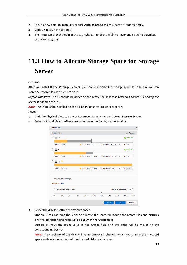
User Manual of iVMS-5200 Professional Web Manager
63
2. Input a new port No. manually or click Auto-assign to assign a port No. automatically.
3. Click OK to save the settings.
4. Then you can click the Help at the top right corner of the Web Manager and select to download
the Watchdog Log.
11.3 How to Allocate Storage Space for Storage
Server
Purpose:
After you install the SS (Storage Server), you should allocate the storage space for it before you can
store the record files and pictures on it.
Before you start: The SS should be added to the iVMS-5200P. Please refer to Chapter 6.3 Adding the
Server for adding the SS.
Note: The SS must be installed on the 64-bit PC or server to work properly.
Steps:
1. Click the Physical View tab under Resource Management and select Storage Server.
2. Select a SS and click Configuration to activate the Configuration window.
3. Select the disk for setting the storage space.
Option 1: You can drag the slider to allocate the space for storing the record files and pictures
and the corresponding value will be shown in the Quota field.
Option 2: Input the space value in the Quota field and the slider will be moved to the
corresponding position.
Note: The checkbox of the disk will be automatically checked when you change the allocated
space and only the settings of the checked disks can be saved.

User Manual of iVMS-5200 Professional Web Manager
64
4. Drag the slider to set the storage percentage of video files and pictures according to actual
requirements.
5. Click Apply to save the settings and click OK to confirm the settings and exit.
Note: After successfully allocating the space, the status of the disk changes to Initialized.
0301001040918

User Manual of iVMS-5200 Professional Web Manager
65