Embed Size (px)
Citation preview

REV 01/20 - 3 - ppd/ehs/ fire sprinkler design.pdf
UD FIRE PROTECTION SPRINKLER DESIGN
UNIVERSITY CONTACT: Environmental Health & Safety
(302) 831-8475
GENERAL INFORMATION:
1. The sprinkler system is to be designed as per State of Delaware Fire Prevention
Regulation with applicable NFPA Codes/Standards applied, and approved by local
jurisdiction. Per Factory Mutual Global Standards, the following requirements must be
met beyond the applicable code. These requirements will be reviewed case by case per
each project and instruct the Consultant as required by Facilities Planning and Project
Delivery (PPD). The sprinkler vendor shall be licensed by the DE State Fire Marshal’s
Office and approved by the UD Fire Marshal.
2. All fire protection equipment/materials shall be U.L. listed and approved by Factory
Mutual Research Corporation. Exceptions to be submitted for review to UD Fire
Marshal with (EHS).
3. The Sprinkler design to be reviewed by Factory Mutual Engineer and UD Fire Marshal
at preliminary and final design stages.
4. A minimum of one (2) copy of sprinkler shop drawings, associated hydraulic calculations,
and equipment cut sheets should be submitted a minimum of 2 weeks in advance of the
start of any work to PPD, with copy of transmittal memo to the University Risk
Management Office.
PPD will disseminate the copies to:
Environmental Health & Safety FM Global Engineering
University of Delaware 2100 Reston Parkway, Suite 600
222 S. Chapel Street Reston, VA 20191
(General Services Building)
Newark, DE 19716 (703) 262-6219
(302) 831-8475
5. The University of Delaware Electric Shop must be notified at (302) 831-2621 to
coordinate ALL sprinkler valve closures a minimum of 24 hours in advance for
proper approval. This advance notice is required for the Electrical shop to survey
the job and implement the use of the Factory Mutual Red Tag Permit System. 6. All sprinkler system designs should include a 10 psi safety factor.
7. Install 2 color plastic engraved plate showing hydraulic design information on riser
8. Use of Post Indicator Valve is required in lieu of curb box valve
9. All sprinkler system design shall be based on isothermal median temperature of zero
degrees F. Provisions to prevent sprinkler freeze-up to include but not limited to supplemental
heating, insulation of pipe, and use of dry pipe sprinklers and dry pendant and sidewall
sprinklers.
REV 01/20 - 4 - ppd/ehs/ fire sprinkler design.pdf
10. Installation Anti-freeze loops are not permitted unless approved by
the UD FireMarshal.
11. Drum Drip Valve locations must be in spaces heated to at least 40 degrees F.
Stairwell Sectional control valves and inspector’s test valves shall be installed at
a height that can be reached by a 5’ stepladder.
12. Sprinkler risers serving more than one floor will have a sectional control
valve serving each floor to allow for draining of a single floor without draining
down other floors. 13. Low point drain locations will be verified during hydrostatic testing and be
installed in accordance with NFPA 13. 14. All drains serving sprinkler main drain (2”) valves shall be piped to the
outside or provided with a drain with sufficient capacity to accommodate flow
without flooding. 15. All steel pipe used shall be no less that Schedule 40.
16. All dry sprinkler and preaction sprinkler types must have supervisory pressure via
Nitrogen Generator or other means approved by UD Fire Marshal.
APPROVED MANUFACTURERS: FM Global Approved and UL Listed
SPECIFICATIONS
PART 1 GENERAL
1.1 DESIGN INFORMATION
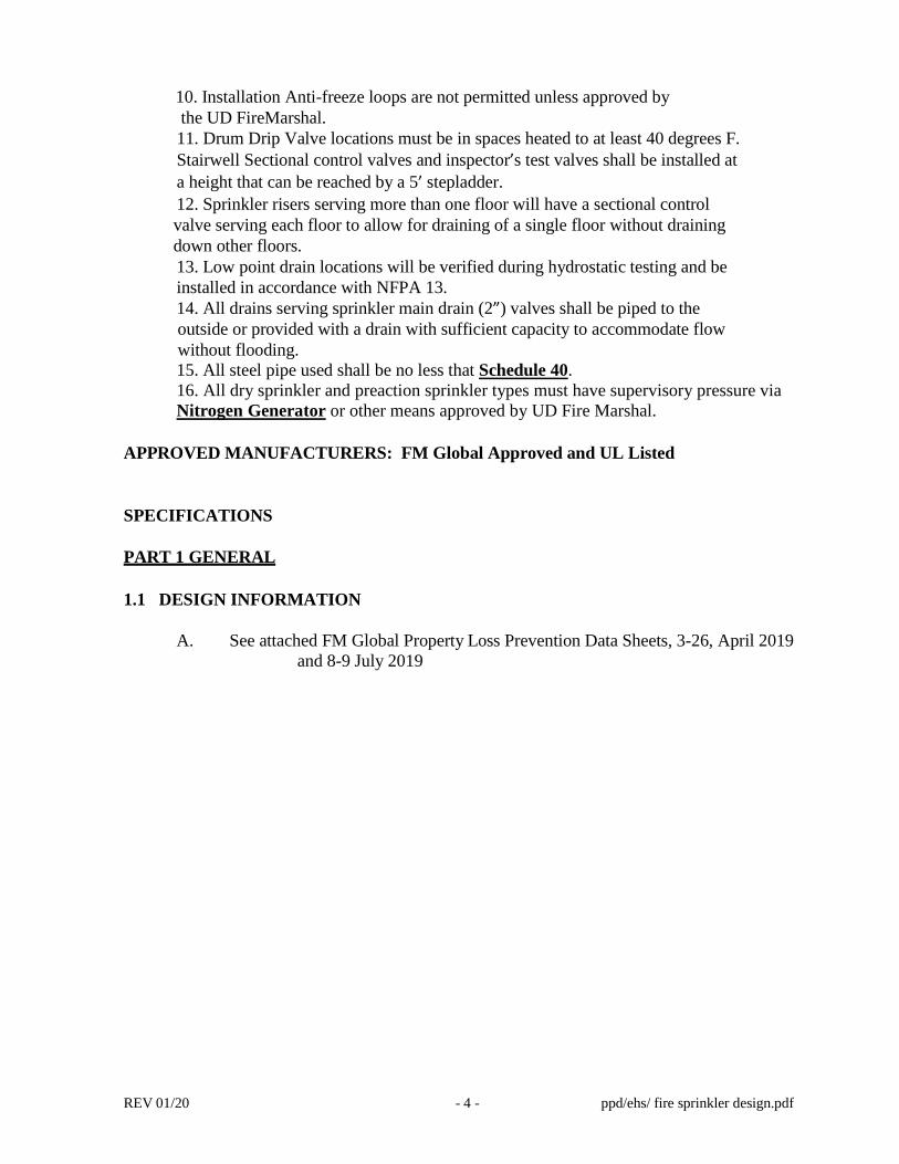
A. See attached FM Global Property Loss Prevention Data Sheets, 3-26, April 2019
and 8-9 July 2019

REV 01/20 - 5 - ppd/ehs/ fire sprinkler design.pdf
B. All other occupancies not specifically listed above will be handled on a
case by case basis. The department of Facilities Planning &
Construction should be contacted to obtain design information.
C. Fire Pumps shall be in accordance with NFPA 20 (current edition); Aurora
Fire Pumps with Patterson Fire Pump Controller is the UD Specification
1. The power supply for electric fire pumps shall be connected before the
building's main electrical disconnect. Power supply protection devises
(fuses or circuit breakers) shall not be installed in the power supply
circuits ahead of the fire pump feeder circuits. The power supply to the
controller shall be run in such a way as to ensure that it would not be
exposed to fire in the building.
2. All electrical plans for fire pumps and controllers shall be
submitted for review and approval by First State Electric
Inspection Agency. Prior to fire pump start-up, a final electrical
inspection by First State Electric Agency shall be performed
and approval provided.
3. A fire pump room shall be provided and shall be constructed of
noncombustible materials having a fire rating of at least 1 hour.
The fire pump room should be accessible to the outdoors.
4. UD utilizes Stephen Brown and Associates (Wilmington, DE) for
fire all pump installations.
1.2 REFERENCE STANDARDS
A. DE State Fire Prevention Regulation (current edition)
B. City of Newark DE Ordinance (Main Campus)
C. National Fire Protection Association (NFPA) standards.
D. FM Global Sprinkler Design Guides (current edition)
E. Underwriters' Laboratories, Inc. (UL) listing
-- END OF SECTION –

April 2019Page 1 of 19
FIRE PROTECTION FOR NONSTORAGE OCCUPANCIES
Table of ContentsPage
1.0 SCOPE ..................................................................................................................................................... 21.1 Changes ............................................................................................................................................ 21.2 Hazard .............................................................................................................................................. 21.3 Superseded Information .................................................................................................................... 2
2.0 LOSS PREVENTION RECOMMENDATIONS ........................................................................................ 22.1 Introduction ........................................................................................................................................ 22.2 Occupancy ......................................................................................................................................... 32.3 Protection ........................................................................................................................................... 4
2.3.1 General ................................................................................................................................... 42.3.2 Incidental Storage ................................................................................................................... 62.3.3 Low-Piled Storage ................................................................................................................... 62.3.4 Storage .................................................................................................................................... 82.3.5 Water Mist Systems ................................................................................................................ 8
3.0 SUPPORT FOR RECOMMENDATIONS ................................................................................................ 93.1 General .............................................................................................................................................. 9
3.1.1 Hazard Categories .................................................................................................................. 93.2 Nonstorage Occupancy Fire Protection ............................................................................................ 9
4.0 REFERENCES ........................................................................................................................................ 94.1 FM Global ......................................................................................................................................... 9
APPENDIX A GLOSSARY OF TERMS ........................................................................................................ 9APPENDIX B DOCUMENT REVISION HISTORY ...................................................................................... 11APPENDIX C HAZARD CATEGORY EXAMPLES ...................................................................................... 13
List of FiguresFig. 1. Flowchart for determining appropriate use of Data Sheet 3-26 ........................................................ 3
List of TablesTable 1. Hazard Categories Based on Predominant Occupancy ................................................................... 4Table 2. Sprinkler Design Demands for Hazard Categories .......................................................................... 5Table 3. Sprinkler Protection Guidelines for Low-Piled Storage .................................................................... 7Table 4. Nonstorage, Non-Manufacturing Occupancies and their Associated Fire Hazard Categories ..... 14Table 4. Nonstorage, Non-Manufacturing Occupancies and their Associated Fire Hazard Categories
(cont’d) ............................................................................................................................................ 15Table 5. Manufacturing Occupancies and Their Associated Fire Hazard Categories .................................. 16Table 5. Manufacturing Occupancies and Their Associated Fire Hazard Categories (cont’d) .................... 17
FM GlobalProperty Loss Prevention Data Sheets 3-26
©2019 Factory Mutual Insurance Company. All rights reserved. No part of this document may be reproduced,stored in a retrieval system, or transmitted, in whole or in part, in any form or by any means, electronic, mechanical,photocopying, recording, or otherwise, without written permission of Factory Mutual Insurance Company.

1.0 SCOPE
This data sheet provides recommendations for fire protection in nonstorage occupancies. A nonstorageoccupancy is an area or building consisting of equipment, processes, and/or materials that are not maintainedin a storage arrangement. These materials may be combustible or noncombustible. The occupancy maycontain industrial or manufacturing processes as well as non-manufacturing operations such as offices, orretail or residential spaces.
1.1 Changes
April 2019. This document has undergone a complete revision. Significant changes include the following:
A. Changed the title of the data sheet from Fire Protection Water Demand for Nonstorage SprinkleredProperties to Fire Protection for Nonstorage Occupancies.
B. Incorporated Engineering Bulletin 04-12, New Protection Guidance for Extended Coverage Sprinklersfor Nonstorage Applications.
C. Moved hazard category examples from Table 1 to Appendix C and expanded them.
D. Added hazard category guidance in Appendix C for recycling, waste processing, and energy from wastefacilities (and the treating of incoming waste material).
E. Added a new flowchart (Figure 1) detailing the proper application of Data Sheet 3-26, including whereother data sheets should be used, and how to treat incidental and low-piled storage.
F. Added protection recommendations for the manufacture and assembly of large, contiguous componentsthat present the hazard of a shielded fire (Section 2.3.1.14).
G. Changed recommended system durations to 60 minutes for all hazard categories (Section 2.3.1.13).
H. Changed recommendations on work-in-process storage. Added new guidance based on testing oflow-piled storage to Table 3. This guidance is engineered toward the levels of storage common tononstorage occupancies. The area limitations for up to Class 3 commodities remain 200 ft2 (20 m2). Thearea limitation for plastic-containing commodities has been reduced from 200 ft2 (20 m2) to 64 ft2 (6 m2,equivalent to four pallet loads).
1.2 Hazard
Refer to the following Understanding the Hazard (UTH) publications for detailed information on the hazardsassociated with this data sheet:
• Combustible Concealed Construction (P0114)
• Fire and Explosion Exposure (P0251)
• Inadequate Automatic Fire Detection (P0247)
• Lack of Automatic Sprinklers (P0037)
• Lack of Emergency Response (P0034)
• Lack of Pre-Incident Planning (P0033)
• Lint (P0315)
1.3 Superseded Information
This document supersedes Engineering Bulletin EB 04-12, New Protection Guidance for Extended CoverageSprinklers for Nonstorage Applications, which has been incorporated into the data sheet.
2.0 LOSS PREVENTION RECOMMENDATIONS
2.1 Introduction
2.1.1 Use FM Approved equipment, materials, and services whenever they are applicable and available.For a list of products and services that are FM Approved, see the Approval Guide, an online resource of FMApprovals.
3-26 Fire Protection for Nonstorage OccupanciesPage 2 FM Global Property Loss Prevention Data Sheets
©2019 Factory Mutual Insurance Company. All rights reserved.
2.2 Occupancy
2.2.1 There may be guidance and recommendations in other data sheets that supersede those within DataSheet 3-26. Use Figure 1 below to determine the appropriate data sheet to use.
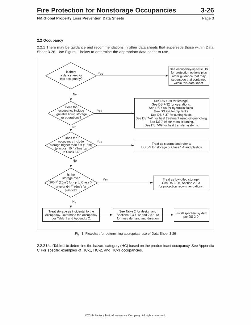
2.2.2 Use Table 1 to determine the hazard category (HC) based on the predominant occupancy. See AppendixC For specific examples of HC-1, HC-2, and HC-3 occupancies.
Fig. 1. Flowchart for determining appropriate use of Data Sheet 3-26
Fire Protection for Nonstorage Occupancies 3-26FM Global Property Loss Prevention Data Sheets Page 3
©2019 Factory Mutual Insurance Company. All rights reserved.
Table 1. Hazard Categories Based on Predominant Occupancy
HazardCategory Predominant Occupancy
HC-1 Areas with light overall combustible loading with limited combustibles used in processes, oroperations of low hazard. This includes combustible furnishings that are typically noncontinuous inwell-subdivided areas. This hazard category does not include any incidental storage of plastics, orplastics used in the construction of walls and/or ceilings.
Examples include residential, offices, noncombustible manufacturing, and hospitals.HC-2 Areas with moderate continuous combustible loading with combustibles in processes, or operations
of moderate hazard due to limited quantities of plastics or ignitable liquids.
Examples include manufacturing, such as machine shops, woodworking, and electronic assembly,as well as retail, theatres, and food production.
HC-3 Areas with generally continuous heavier combustible loading with limited quantities of ignitableliquids and/or heavier amounts of plastics.
Examples include plastic manufacturing, vehicle manufacturing and assembly, and printing plants.
2.2.3 Classify buildings that are of wood construction but otherwise contain no combustible materials as HC-1occupancies.
2.2.4 Identify spaces concealed from ceiling sprinklers that have combustible construction features or containcombustible material and provide sprinkler protection in those spaces. Concealed spaces can includeequipment with combustible material; areas obstructed by ductwork, light fixtures, or hoods; and hiddencombustible construction.
2.2.4.1 Protect combustible concealed spaces as HC-1 in accordance with FM Global Data Sheet 1-12,Ceilings and Concealed Spaces.
2.2.4.2 Protect other shielded areas, including machine covers, spray booths, ovens, printing presses,combustible ductwork, plastic tanks, and conveyors, as follows:
A. Where a data sheet relevant to these hazards or occupancies exists, adhere to the recommendationsin that data sheet.
B. Otherwise, protect underneath the shielded area with sprinklers providing the same density as the ceilingsystem and in accordance with Data Sheet 2-0, Installation Guidelines for Automatic Sprinklers.
2.2.5 For locations with mixed occupancy hazards that are not separated by fire partitions, protect for thegreatest hazard or see Data Sheet 2-0 for other protection options.
2.2.6 Establish and implement a housekeeping program to minimize accumulations of lint, dust, and othercombustible materials.
2.3 Protection
2.3.1 General
2.3.1.1 See Data Sheet 1-57, Plastics in Construction, for protection guidance when building constructioncontains plastic.
2.3.1.2 Install sprinklers in accordance with Data Sheet 2-0, Installation Guidelines for Automatic Sprinklers.
2.3.1.3 In addition to the recommendations in this data sheet, refer to Data Sheet 2-8, Earthquake Protectionfor Water-Based Fire Protection Systems, for facilities located in earthquake-prone regions.
2.3.1.4 Install a wet pipe, dry pipe, pre-action, or antifreeze sprinkler system to protect nonstorageoccupancies. An FM Approved water mist system may also be used to protect HC-1 occupancies (see Section2.3.5).
2.3.1.5 Use wet-pipe sprinkler systems unless the protected area is refrigerated or unheated, and thetemperature can fall below 40°F (4°C). See Data Sheet 2-0, Section 2.4, for further information. For wet-pipesprinkler systems, use the following sprinklers:
• Sidewall (HC-1 and HC-2 occupancies only), pendent, upright, or dry-pendent.
3-26 Fire Protection for Nonstorage OccupanciesPage 4 FM Global Property Loss Prevention Data Sheets
©2019 Factory Mutual Insurance Company. All rights reserved.

• Nominal 160°F (70°C) temperature rating. Only use sprinklers with a nominal temperature rating of 212°F(100°C) where the ambient temperature is in excess of 100°F (38°C).
• Standard coverage or extended coverage.
• Standard response or quick response. Do not use standard response sprinklers when ceiling heights aregreater than 60 ft (18 m).
2.3.1.6.1 Use the following sprinklers for dry-pipe sprinkler systems:
• Upright or dry-pendent. Dry sidewall can be used under certain conditions; see Data Sheet 2-0.
• Nominal 280°F (140°C) temperature rating. Nominal 165°F (70°C) sprinklers are acceptable for HC-1 andHC-2 occupancies.
• Standard coverage.
• Standard response. Quick-response sprinklers are acceptable for HC-1 and HC-2 occupancies.
2.3.1.6.2 For dry-pipe and equivalent sprinkler systems, if a maximum water delivery time is not specifiedin an occupancy-specific data sheet, us one of the following water delivery times:
• 60 seconds with the operation of the single most remote sprinkler
• 40 seconds with the operation of the most remote four sprinklers (two sprinklers on two lines)
2.3.1.7 Treat single-interlocked preaction sprinkler systems as either wet-pipe or dry-pipe systems. Treatnon-interlocked or double-interlocked preaction sprinkler systems as dry-pipe systems. See Data Sheet 5-48for additional guidance on preaction systems, including detector spacing.
2.3.1.8 Treat anti-freeze sprinkler systems as wet-pipe systems. See Data Sheet 2-0, Installation Guidelinesfor Automatic Sprinklers, for additional guidance antifreeze solution sprinkler systems.
2.3.1.9 Use minimum sprinkler K-factors in accordance with FM Global Data Sheet 2-0, Installation Guidelinesfor Automatic Sprinklers.
2.3.1.10 Design the sprinkler system in accordance with Table 2, based on the applicable hazard category.
Table 2. Sprinkler Design Demands for Hazard Categories
HazardCategory
Ceiling Height up to 30 ft(9 m)Note 2
Ceiling Height 30-45 ft(9-13.5 m)
Ceiling Height 45-60 ft(13.5-18 m)
Ceiling Height 60-100 ft(18-30 m)
(gpm/ft2)/ft2 [(mm/min)/m2]Wet Dry Wet Dry Wet Dry Wet Dry
HC-1 0.1/1500(4/140)
Note 10.1/1500(4/140)
0.2/2500(8/230)
0.2/3500(8/330)
0.2/2500(8/230)
0.2/3500(8/330)
0.6/1200(24/110)
Designguidancecurrently
unavailable.HC-2 0.2/2500
(8/230)0.2/3500(8/330)
0.2/2500(8/230)
0.2/3500(8/330)
0.2/2500(8/230)
0.2/3500(8/330)
0.6/1200(24/110)
HC-3 0.3/2500(12/230)
0.3/3500(12/330)
0.3/3600(12/340)
0.3/4600(12/430)
0.5/3000(20/280)
0.5/4000(20/370)
0.6/1200(24/110)
Note 1. The demand area for dormitories, residential, and dwelling type areas may be based on the largest room area, but not less thanfour sprinklers provided fire compartmentation with a minimum one hour fire rating is present. Treat corridors as rooms in making thisdetermination.
Note 2. For HC-2 and HC-3 occupancies with ceiling heights up to 30 ft (9 m) where K11.2EC or K14.0EC upright 160°F (70°C) ratedsprinklers are used, the design can be reduced to the following:
• K11.2EC: 0.30 gpm/ft2 over 1500 ft2 (12mm/min over 140 m2). Ensure a minimum of 6 sprinklers in the design• K14.0EC 0.30 gpm/ft2 over 1000 ft2 (12mm/min over 90 m2). Ensure a minimum of 4 sprinklers in the design
2.3.1.11 Regardless of the design demands in Table 2, provide a minimum design pressure at the most remotesprinkler per the sprinkler’s FM Approval listing.
2.3.1.12 Provide a hose stream allowance of 250 gpm (950 L/min) for HC-1 and HC-2 occupancies, and ahose stream allowance of 500 gpm (1900 L/min) for HC-3 occupancies.
Fire Protection for Nonstorage Occupancies 3-26FM Global Property Loss Prevention Data Sheets Page 5
©2019 Factory Mutual Insurance Company. All rights reserved.

2.3.1.13 Ensure a water supply capable of providing the design sprinkler discharge flow rate plus hose streamfor 60 minutes for all hazard categories.
2.3.1.14 Manufacturing and assembly of large, contiguous components, such as large aircraft, boats, andwind turbine blades, create the potential for shielded fires. The presence of these operations represents anincreased fire hazard beyond typical HC-2 or HC-3 occupancies. For ceilings below 60 ft (18 m) use Table2. For ceilings above 60 ft (18 m) protect these areas with K25.2 (K360) sprinklers using a design of 12sprinklers at 50 psi (2.5 bar).
2.3.2 Incidental Storage
2.3.2.1 Treat storage of Class 1-3 commodities up to 10 ft (3 m) high and no more than 200 ft2 (20 m2) inarea as incidental to the occupancy. Provide protection using Table 2.
2.3.2.2 In HC-2 and HC-3 occupancies, treat storage of plastic commodities up to 6 ft (1.8 m) high and nomore than 64 ft2 (6 m2) in area (approximately four pallets) as incidental to the occupancy. Provide protectionusing Table 2.
2.3.2.3. Multiple areas of storage within the limits listed in Sections 2.3.2.1 and 2.3.2.2 may still be consideredas incidental to the occupancy if separated by aisles not less than 8 ft (2.4 m) wide.
2.3.3 Low-Piled Storage
2.3.3.1 Where storage exceeds the area limitations in Section 2.3.2.1 and 2.3.2.2 but not the height limitations,treat it as low-piled storage and provide protection in accordance with Table 3.
3-26 Fire Protection for Nonstorage OccupanciesPage 6 FM Global Property Loss Prevention Data Sheets
©2019 Factory Mutual Insurance Company. All rights reserved.

Table 3. Sprinkler Protection Guidelines for Low-Piled Storage
Wet System, Pendent Sprinklers, 160°F (70°C), Number of AS @ psi (bar)Commodity Max. Ceiling
Height, ft (m)Quick-Response Standard-Response
K11.2 (K160) K14.0 (K200) K16.8 (K240) K22.4 (K320) K25.2 (K360) K25.2EC(K360EC)
K11.2 (K160) K14.0 (K200) K19.6 (K280) K25.2 (K360)
Up to CEPNote 1
30 (9) 25 @ 7 (0.5) 25 @ 7 (0.5) 25 @ 7 (0.5) 25 @ 15 (1) 25 @ 15 (1) 6 @ 52 (3.5) 25 @ 7 (0.5) 25 @ 7 (0.5) 25 @ 16 (1) 25 @ 15 (1)45 (14) 25 @ 16 (1) 25 @ 10 (0.7) 25 @ 7 (0.5) 25 @ 15 (1) 25 @ 15 (1) 6 @ 52 (3.5)60 (18) 25 @ 16 (1) 25 @ 10 (0.7) 25 @ 7 (0.5) 25 @ 15 (1) 25 @ 15 (1) 6 @ 52 3.5)
UUP 30 (9) 25 @ 50 (3.4) 10 @ 62 (4.3) 10 @ 43 (3) 14 @ 24 (1.7) 14 @ 19 (1.3) 25 @ 50 (3.4) 25 @ 15 (1)45 (14) 10 @ 62 (4.3) 10 @ 43 (3) 14 @ 24 (1.7) 14 @ 19 (1.3)60 (18) 10 @ 50 (3.4) 10 @ 40 (2.8)
Wet System, Upright Sprinklers, 160°F (70°C), Number of AS @ psi (bar)Commodity Max. Ceiling
Height, ft (m)Quick-Response Standard-Response
K11.2 (K160) K14.0 (K200) K14.0EC(K200 EC)
K16.8 (K240) K25.2EC(K360EC)
K11.2 (K160) K16.8 (K240) K25.2 (K360)
Up to CEPNote 1
30 (9) 25 @ 7 (0.5) 25 @ 7 (0.5) 6 @ 73 (5) 25 @ 7 (0.5) 6 @ 52 (3.5) 25 @ 7 (0.5) 25 @ 7 (0.5) 25 @ 7 (0.5)45 (14) ) 25 @ 16 (1) 25 @ 10 (0.7) 25 @ 7 (0.5) 6 @ 52 (3.5)60 (18) 25 @ 16 (1) 25 @ 10 (0.7) 25 @ 7 (0.5) 6 @ 52 (3.5)
UUP 30 (9) 25 @ 50 (3.4) 10 @ 62 (4.3) 10 @ 43 (3) 25 @ 50 (3.4) 25 @ 22 (1.5) 25 @ 15 (1)45 (14) 10 @ 62 (4.3) 10 @ 43 (3)60 (18)
1 Protect Class 1-3 commodities stored up to 10 ft (3 m) high using the guidelines for CEP commodities stored under a 30 ft (9 m) ceiling.
Fire
Pro
tection
for
No
nsto
rage
Occu
pan
cies3-26
FM
Glo
bal
Pro
perty
Lo
ssP
reventio
nD
ataS
heets
Page
7
©2019
Factory
MutualInsurance
Com
pany.Allrights
reserved.
2.3.4 Storage
2.3.4.1 Where the storage height limitations in Section 2.3.2.1 and 2.3.2.2 are exceeded, protect the storagearea in accordance with Data Sheet 8-9, Storage of Class 1, 2, 3, and 4 and Plastic Commodities.
2.3.5 Water Mist Systems
2.3.5.1 Water mist systems with FM Approval for light hazard occupancies may be used to provide soleprotection for HC-1 Occupancies (i.e., in lieu of automatic sprinkler protection) when all of therecommendations in this section are met. Do not use water mist systems to protect HC-2 or HC-3occupancies.
2.3.5.2 Install water mist systems in accordance with the recommendations in this section, the system’s FMApproval Guide listing, and the manufacturer’s FM Approved design, installation, operation and maintenancemanual. Refer to Data Sheet 4-2, Water Mist Systems, for additional installation recommendations.
2.3.5.3 Limit the use of water mist systems to wet pipe distribution systems.
2.3.5.4 Limit the use of water mist systems to areas with the following types of smooth, flat ceilings and withceiling slopes not exceeding 1 in./ft (83 mm/m):
• Flat slab, reinforced concrete
• Smooth, monolithic ceilings attached to the underside of wood joists, wood trusses and bar joists
• Suspended ceilings
2.3.5.5 Determine the design area based on the following:
A. For systems FM Approved for an unrestricted enclosure area, design the water mist system to supplywhichever of the following is greater:
1. The hydraulically most remote nine (9) automatic nozzles
2. All automatic nozzles within a 1500 ft2 (140 m2) demand area
B. For systems FM Approved with a specified maximum enclosure area, design the water mist system tosupply all automatic nozzles within the compartment.
C. For systems in corridors that can be protected by one row of nozzles, design the water mist system tosupply whichever of the following is less:
1. A maximum of five (5) automatic nozzles for the demand area.
2. In an unrestricted enclosure area, all automatic nozzles within a 1500 ft2 (140 m2) demand area.3. For corridors smaller than 1500 ft2 (140 m2) all automatic nozzles in the area.
2.3.5.6 Install automatic nozzles using the following as specified in the system’s FM Approval Guide listingand FM Approved design, installation, operation and maintenance manual:
• Minimum linear spacing
• Maximum linear spacing, but not to exceed 16 ft (4.9 m)
• Maximum distance from the wall
• Maximum ceiling height
• Maximum clearance between ceiling and nozzle
• Obstructions
• Minimum operating pressure (for each nozzle within the design area)
• Minimum fire resistance of enclosure 30 minutes
2.3.5.7 Provide a water supply capable of supplying the maximum water mist system demand for the designarea, plus 250 gpm (950 L/min) for hose streams, for a duration of 60 minutes.
3-26 Fire Protection for Nonstorage OccupanciesPage 8 FM Global Property Loss Prevention Data Sheets
©2019 Factory Mutual Insurance Company. All rights reserved.
3.0 SUPPORT FOR RECOMMENDATIONS
3.1 General
3.1.1 Hazard Categories
This data sheet recommends sprinkler protection based on the expected fire hazard of a building or area.The fire hazard depends on the occupancy, exposure, and combustible loading. This data sheet approximatesan area’s fire hazard by assigning a hazard category (HC) to the area, where HC-1, HC-2, and HC-3represent an increasing hazard level with the potential for a more severe fire event.
A nonstorage occupancy is an area or building consisting of equipment, processes, and/or materials thatare not maintained in a storage arrangement. These materials may be combustible or noncombustible. Theoperation may include industrial or manufacturing processes, as well as nonmanufacturing locations suchas offices or residential spaces. Other codes and standards may refer to these areas as “light hazard” or“ordinary hazard” occupancies.
3.2 Nonstorage Occupancy Fire Protection
Automatic sprinkler protection is the best defense against a fire. Sprinklers have proven to be the mostpractical and reliable means of controlling a fire in business and industry. Sprinkler protection minimizes notonly fire damage, but also nonthermal damage, and allows for quick resumption of normal operations.Sprinklers are needed wherever the building construction or occupancy is combustible.
The majority of fires in nonstorage occupancies in buildings with lower ceiling heights are controlled orextinguished as long as a sufficient sprinkler density is provided over a reasonable operating area. Variationsin attributes such as temperature rating, RTI, orientation, and orifice size, among others, have had a limitedeffect on sprinkler performance in nonstorage occupancy fires, provided no critical deficiencies exist (e.g.,obstruction to sprinkler discharge, a lack of sprinklers underneath obstructions or within concealed spaces).
Where the fire hazard exceeds that of a typical nonstorage occupancy, enhanced sprinkler protection maybe needed, and the sprinkler system’s performance may become more sensitive to specific automatic sprinklerattributes. Examples of these increased fire hazards include the following:
• The presence of storage
• The presence of combustible deposits such as dust, lint, oil, or other residues
• The presence of ignitable liquids
4.0 REFERENCES
4.1 FM Global
Data Sheet 2-0, Installation Guidelines for Automatic SprinklersData Sheet 5-12, Electric AC GeneratorsData Sheet 5-14, TelecommunicationsData Sheet 5-23, Emergency and Standby Power SystemsData Sheet 7-4, Paper Machines and Pulp DryersData Sheet 7-29, Ignitable Liquid Storage in Portable ContainersData Sheet 7-32, Ignitable Liquid OperationsData Sheet 7-64/13-28, Aluminum IndustryData Sheet 7-93N, Aircraft HangarsData Sheet 7-96, Printing PlantsData Sheet 7-98, Hydraulic FluidsData Sheet 8-3, Rubber Tire StorageData Sheet 8-9, Storage of Class 1, 2, 3, 4 and Plastic CommoditiesData Sheet 8-21, Roll Paper Storage
APPENDIX A GLOSSARY OF TERMS
Approval Guide: An online resource of FM Approvals that provides a guide to equipment, materials, andservices that have been FM Approved for property conservation.
Fire Protection for Nonstorage Occupancies 3-26FM Global Property Loss Prevention Data Sheets Page 9
©2019 Factory Mutual Insurance Company. All rights reserved.
Combustible occupancy: An occupancy that contains sufficient combustible materials to allow horizontalfire spread throughout a given area in the absence of sprinkler protection; or an occupancy that contains asufficient concentration of combustibles to cause significant damage to a building.
Commodity: A combination of material, external packaging (e.g., container), and material handling aids (e.g.,pallets). The purpose of assigning a commodity classification is to determine the proper level of fire protection.A commodity classification is dependent on how the commodity burns and how the burning commodityresponds to the application of sprinkler discharge. Refer to Data Sheet 8-1, Commodity Classification, forfurther information on specific commodities.
Demand area: The expected area of sprinkler operation, based on the hazard being protected, used forhydraulic design purposes. In English units it is expressed in ft2; in metric units, m2 (1 ft2 = 0.093 m2).
Dry-pipe sprinkler system: A sprinkler system that is located downstream of a dry-pipe valve. It is filledwith a pressurized gaseous medium (typically air or an inert gas such as nitrogen) for the purpose ofmaintaining the dry-pipe valve closed. Upon sprinkler actuation, the pressure within the sprinkler systembegins to drop until the pressure becomes too low to keep the dry-pipe valve closed. At this time the dry-pipevalve opens (trips) allowing water to fill the sprinkler system and discharge through any sprinklers that havebeen actuated. A dry-pipe sprinkler system is typically used in areas where the presence of water withinthe sprinkler system is not suitable.
Density: The amount of water applied by sprinklers over a given area in a certain amount of time. In Englishunits, it is expressed in gpm/ft2; in metric units, in mm/min (1 gpm/ft2 = 40.74 mm/min).
Duration or system duration: Water supply system duration is a defined time period between when a fireinitially activates a sprinkler system and when the fire is extinguished. Fire extinguishment usually isaccomplished by the manual firefighting efforts of public fire service personnel, facility fire service personnel,or facility emergency response team personnel. Duration takes into consideration the commodity hazard’sexpected fire size in the presence of the system’s specific sprinklers and bases the design, as well as manualextinguishment by either one or two applied hose streams.
Extended-coverage sprinklers: The physical characteristics of extended-coverage (EC) sprinklers aresimilar to those of sprinklers for use with standard spacing. However, the deflector designs are enhancedto ensure proper uniformity and effectiveness of water distribution for the spacing and design pressures forwhich they are FM Approved.
FM Approved: Products and services that meet the requirements for FM Approval. See the Approval Guidefor a list of products and services that are FM Approved.
Hose demand: The water flow required for hoses (common sizes are 2-1/2 in. and 1-1/2 in.). In Englishunits it is expressed in gpm; in metric units, L/min.
Incidental storage: Storage that is normal for an occupancy (e.g., small amounts of packaging, raw materials,or the products being made). This is likely to be at the start or end of a production line and should not exceedthe height and area limitations detailed in Section 2.3.2.1 and 2.3.2.2.
Library stack rooms: Rooms that house typical library bookshelves of approximately 8 ft (2.4 m) in height,containing books stored vertically on end, held in place in close association with each other, with aisles widerthan 30 in. (762 mm).
Low-piled storage: Storage that is in excess of the area limitations detailed in Section 2.3.2.1 and 2.3.2.2so cannot be considered incidental storage but does not exceed the height limitations and therefore canbe protected in accordance with Table 3 and does not need to be evaluated per Data Sheet 8-9.
Nonstorage automatic sprinkler: A sprinkler that has been categorized by FM Global as acceptable forprotecting nonstorage occupancies and/or any other low to moderate heat-release-rate fires as recommendedin an applicable occupancy-specific data sheet.
Nonstorage occupancy: An occupancy consisting of combustible or noncombustible materials that are notmaintained in a storage arrangement. May contain incidental storage or low-piled storage.
Quick-response (QR) sprinklers: QR sprinklers are similar to standard-response sprinklers, except theyuse a fast-response, heat-actuated element.
Sprinkler demand: The amount of water flow required for sprinkler protection. In English units it is expressedin gpm; in metric units, L/min (1 gpm = 3.79 L/min).
3-26 Fire Protection for Nonstorage OccupanciesPage 10 FM Global Property Loss Prevention Data Sheets
©2019 Factory Mutual Insurance Company. All rights reserved.
Waterflow alarm: A device that is installed on a sprinkler system and arranged to provide an alarm whenone or more sprinklers operate.
Total water demand: The water flow required for both sprinklers and hoses (i.e., total water demand is equalto sprinkler demand plus hose demand). Hose demand is not always provided by the sprinkler system. InEnglish units it is expressed in gpm; in metric units, L/min.
APPENDIX B DOCUMENT REVISION HISTORY
April 2019. This document has undergone a complete revision. Significant changes include the following:
A. Changed the title of the data sheet from Fire Protection Water Demand for Nonstorage SprinkleredProperties to Fire Protection for Nonstorage Occupancies.
B. Incorporated Engineering Bulletin 04-12, New Protection Guidance for Extended Coverage Sprinklersfor Nonstorage Applications.
C. Moved hazard category examples from Table 1 to Appendix C and expanded them.
D. Added hazard category guidance in Appendix C for recycling, waste processing, and energy from wastefacilities (and the treating of incoming waste material).
E. Added a new flowchart (Figure 1) detailing the proper application of Data Sheet 3-26, including whereother data sheets should be used, and how to treat incidental and low-piled storage.
F. Added protection recommendations for the manufacture and assembly of large, contiguous componentsthat present the hazard of a shielded fire (Section 2.3.1.14).
G. Changed recommended system durations to 60 minutes for all hazard categories (Section 2.3.1.13).
H. Changed recommendations on work-in-process storage. Added new guidance based on testing oflow-piled storage to Table 3. This guidance is engineered toward the levels of storage common tononstorage occupancies. The area limitations for up to Class 3 commodities remain 200 ft2 (20 m2). Thearea limitation for plastic-containing commodities has been reduced from 200 ft2 (20 m2) to 64 ft2 (6 m2,equivalent to four pallet loads).
April 2014. Table 2a, Sprinkler Design Demands for Hazard Categories with Ceiling Heights up to 100 ft(30 m): The design listed for the K25.2EC (K360EC) sprinkler has been revised to provide the same designdensity as listed for the K25.2 (K360) design. Additionally, Table 2a has been revised include both uprightand pendent sprinkler applications.
July 2011. Minor editorail changes and clarifications to Recommendations 2.1.1.1 and 2.1.1.10.1 were madefor this revision.
January 2011. This document has been updated. The following is a list of the changes:
• Realigned atriums, school & university classrooms, gymnasiums, metalworking and fabrication shops withnon-hydraulic operations, and mineral operations to a more suited hazard category of HC-1 based on theirlight loading occupancy description.
• Re-evaluated Extended Coverage sprinkler design guidelines based on full scale fire test results.
• Added Extended Coverage Sprinklers K11.2EC (K160) and K14.0EC (K200EC) with a temperature ratingof 160°F (70°C) as options for new installations in HC-2 & HC-3 occupancies with ceiling heights up to30 ft (9 m).
• Deleted design requirement to supply the hydraulically most remote 9 sprinklers when using EC sprinklersfor HC-1 and HC-2 occupancies.
• Reduced the wet and dry sprinkler design demand areas for HC-3 occupancies with ceilings up to 30 ft(9 m).
• Reduced the minimum water demand duration to 60 minutes for HC-2 occupancies.
• Removed any and all references to HC-4 categories due to vague occupancy description not fitting anycomparable manufacturing sites.
Fire Protection for Nonstorage Occupancies 3-26FM Global Property Loss Prevention Data Sheets Page 11
©2019 Factory Mutual Insurance Company. All rights reserved.
• Reduced the minimum sprinkler K-Factors for new installations to K8.0 (K115) for HC-2 occupancies withceiling heights up to 60 ft (18 m).
• Added protection option for HC-3 occupancies over 60 ft (18m) and up to 100 ft (30 m).
• Added guidelines covering acceptability for using storage sprinklers in mixed storage and Nonstorageoccupancies.
• Added protection guidelines for use of water mist systems.
March 2010. This document has been completely rewritten. The following is a list of major changes:
• Added a table of hazard categories based on occupancy.
• Added a table of sprinkler design demands based on ceiling height and type of sprinkler system for eachhazard category.
• Added design information on extended-coverage sprinklers for light- and ordinary-hazard occupancies.
• Added sprinkler protection design criteria for nonstorage and nonmanufacturing facilities with ceilingshigher than 60 ft (20 m) and up to 100 ft (30 m).
• Added sprinkler protection design criteria for manufacturing facilities with ceilings up to 60 ft (20 m) high.
• Revised loss history.
• Updated Appendix A, Glossary of Terms.
July 2008. References to FM Global Loss Prevention Data Sheet 7-96, Printing Plants, were added to Table 1.
May 2008. Clarifications were made to the recommendations 2.1.1.1 and 2.1.2.1.2.
January 2008. The following changes were made:
1. Combined Tables 2 through 10 to simplify the recommendations for sprinkler system water demand.
2. Replaced Table 1, which described temperature ratings for sprinklers, with a recommendation to use 160°F(70°C) and 280°F (140°C) temperature-rated sprinklers for wet and for dry systems respectively.
3. Added sprinkler system water demand information for assembly facilities manufacturing fiberglass boats.
January 2006. Clarification was made to the recommendation 2.1.2.3.1 and Table 11.
January 2005. Protection criteria has been provided for light, moderately and heavily loaded nonstorageareas with floor to ceiling clearances up to 60 ft (18.3 m). Storage type, storage and building height andcorresponding protection criteria are provided in Table 11.
January 2001. The protection requirements for the spray application of flammable liquids, including catalyticspraying have been removed from this data sheet and are included in Data Sheet 7-27, Spray Applicationof Flammable and Combustible Materials.
The protection requirements for hydraulic equipment using hydraulic fluids have been removed from thisdata sheet. The protection requirements are in Data Sheet 7-98, Hydraulic Fluids.
September 2000. This revision of the document was reorganized to provide a consistent format.
October 1992. The following changes were made for this revision:
1. Flammable Liquids
Water demand criteria for flammable liquids in open and closed tanks are not contained in this revision ofData Sheet 3-26. In the previous revision of this data sheet, the occupancies were titled Flammable LiquidsIn Open Tanks and Containers and Flooding Systems and Flammable Liquids in Closed Containers, ExceptDrum Storage. Water demand criteria for these occupancies are incorporated with the flammable liquid datasheets.
2. Woodworking Occupancy
Water demand criteria for the general occupancy, Woodworking, are not in this revision of Data Sheet 3-26.Data Sheet 7-10, Wood Processing and Woodworking Facilities, has been revised (June 1991). Waterdemand information is now included in Data Sheet 7-10.
3-26 Fire Protection for Nonstorage OccupanciesPage 12 FM Global Property Loss Prevention Data Sheets
©2019 Factory Mutual Insurance Company. All rights reserved.
3. Textile Occupancy
Water demand criteria for the textile occupancy are not in this revision of Data Sheet 3-26. Data Sheet 7-1,Fire Protection for Textile Mills, has been revised. Water demand information is now included in Data Sheet7-1.
4. Miscellaneous Occupancies
The section titled ″Miscellaneous Occupancies″ is included to provide guidelines for occupancies that arenot found within the specific occupancies.
5. Miscellaneous Nonmanufacturing
The title ″Miscellaneous Nonmanufacturing″ is used in place of ″Light Hazard Occupancy.″ The new titlebetter defines the various occupancies involved.
6. Office Occupancies
Guidelines in Data Sheet 3-26 for office occupancy are in Table 2, within the section titled MiscellaneousNonmanufacturing. Loss data (see Support for Recommendations) and fire test data indicate that a watersupply capable of providing a density of 0.10 gpm/ft2 (4 mm/min) over an area of 1500 ft2 (140 m2) will provideadequate protection for an office occupancy.
7. Electronic-Electrical Manufacturing and Assembly
A separate occupancy category for electronic and electrical manufacturing and assembly occupancies hasbeen added.
8. Plastics Processing
Recent fire tests indicate that ordinary, intermediate or high temperature rated sprinklers over 2500 ft2
(230 m2) (dry system: 3500 ft2 ) will provide adequate protection over this occupancy.
9. Quick Response Automatic Sprinklers (QRAS)
This data sheet includes guidance on the use of QRAS. The recommendations are based on the results offire tests comparing QRAS and conventional response automatic sprinklers.
10. Title Change
The title change to include ″Nonstorage″ better describes the occupancies included within this data sheet.
11. International and National Fire Protection Association Standards
APPENDIX C HAZARD CATEGORY EXAMPLES
Table 1 of this data sheet provides a description of what a typical HC-1, HC-2, and HC-3 occupancy mayinclude, but this table should not be viewed as an all inclusive list. Judgment is needed when determining anoccupancy’s hazard category.
Tables 4 and 5 provide specific examples of different occupancies and their associated hazard category,as well as any further guidance that may be applicable.
It should be noted that although a location may have a predominant occupancy of HC-1 or HC-2, considerationshould be given to areas that owing to a higher hazard process or presence of higher hazard materials (suchas plastics) may need to be afforded a greater level of protection such as HC-2 or HC-3 respectively. Forexample, a HC-2 metal manufacturing facility may have plating operations that would necessitate an HC-3level of protection in those areas.
Fire Protection for Nonstorage Occupancies 3-26FM Global Property Loss Prevention Data Sheets Page 13
©2019 Factory Mutual Insurance Company. All rights reserved.
Table 4. Nonstorage, Non-Manufacturing Occupancies and their Associated Fire Hazard Categories
Occupancy DescriptionHazard
Category ConsiderationsHealthcareFacilities
- Hospitals and Hospital Laboratories- Nursing or Convalescent Homes- Kitchens- Care Homes- Penal Institutions (Jailhouses, etc.)
HC-1 Data sheets to consider:- 1-3, High Riser Buildings- 1-12, Ceilings and Concealed Spaces- 1-24, Protection Against Liquid Damage- 5-23, Emergency and Standby Power
Systems- 6-4, Oil or Gas Fired Single-Burner
Boilers- 6-5, Oil or Gas Fired Multiple Burner
Boilers- 7-15, Garages- 7-52, Oxygen
- Hospital Utility Plants HC-2- Storage Room/Pharmacies with Storage HC-3
BusinessFacilities &Apartments
- Offices- Hotels- Flats / Apartments
HC-1 Data sheets to consider:- 1-3, High Rise Buildings- 1-12, Ceilings and Concealed Spaces- 1-24, Protection Against Liquid Damage- 7-15, Garages
- Utility Rooms HC-2
EducationalFacilities
- Universities- Schools- Kindergartens- Colleges- Dormitories and Residence Halls- Prisons- Detention centers
HC-1 Data sheets to consider:- 1-3, High Riser Buildings- 1-12, Ceilings and Concealed Spaces- 1-24, Protection Against Liquid Damage- 5-23, Emergency and Standby Power
Systems- 7-15, Garages
- Utility Rooms HC-2Transport &Logistic
- Airport Terminal- Bus Stations- Train Stations- Ferry Port- Cruise Terminal- Bicycle Parks
HC-1 Data sheets to consider:- 7-11, Conveyors- 7-15, Garages- 7-29, Ignitable Liquid Storage in Portable
Containers- 7-32, Ignitable Liquid Operations- 7-93, Aircraft Hangars, Aircraft
Manufacturing and AssemblyFacilities, and Protection of AircraftInteriors During Assembly
- 8-3, Rubber Tire Storage- 8-9, Storage of Class 1, 2, 3, 4 and
Plastic Commodities
- Parking Garage- Car Parks
HC-2
- Car-Sized Vehicle Repair Garages andAssembly Operations Where UnfueledVehicles are Repaired, Tested orAssembled
- Truck Loading Docks - loading andunloading canopies
- Package Delivery/Distribution Hubs- Cross docking areas- Aircraft Hangar,- Zeppelin Hangar
HC-3
Energy ServiceProviders
- Gas and Oil Stations/Service Provider- Battery Stations- Solar Plant- Wind Turbines- Photo Voltaic Farms
HC-3 Data sheets to consider:- 3-10, Wind Turbines
3-26 Fire Protection for Nonstorage OccupanciesPage 14 FM Global Property Loss Prevention Data Sheets
©2019 Factory Mutual Insurance Company. All rights reserved.
Table 4. Nonstorage, Non-Manufacturing Occupancies and their Associated Fire Hazard Categories (cont’d)
Occupancy DescriptionHazard
Category ConsiderationsLeisure Facilities& PublicAssembly
- Museums and Monuments- Restaurants (Seating Areas)- Gyms- Places of Worship- Ski Lift Station- Zoo / Aquarium- Auditoriums- Aquatic Center (Swimming Pool/ Spa)- Theatres- Cinemas- Convention Centers- Theme Parks- Libraries
HC-1 - Theaters, auditoriums, and casinos maysometimes qualify as HC-1 occupancieswhen ordinary combustibles loading isminimal, or the construction of thebuilding is noncombustible. For example,casino areas with ceilings under 30 ft (9m) high and only lined with slot machineswould qualify as HC-1. Auditoriums ortheaters, including staging practicallyempty of ordinary combustibles, wouldalso qualify. Consider backstage andbelow stage areas without storage to beHC-2.
- Large convention centers have thepotential to display products that havehigh amounts of plastic and/or haveconcealed spaces.
- Sport Arena- Theaters- Casinos- Night Clubs
HC-2
- Exhibition Halls- Theatre: Backstage and Below Stage
Areas.- Convention Centers
HC-3
MercantileFacilities
- Department Stores - front of house- Shopping Malls- Retail and Mercantile Areas- Supermarkets
HC-2 - In general storage at these locations isretail items on display to less than 6 ft(1.8 m) (or as high as can be reachedwithout equipment).
- Back of house and bulk storage areas,wholesale/big-box stores, should beanalyzed in line with Data Sheet 8-9,Storage of Class 1, 2, 3, 4 and PlasticCommodities.
Incoming WasteMaterial atRecycling/WasteProcessing/Energy fromWaste Facilities
- Mixed household/business waste orrecyclables including metal, glass,cellulosic materials and small amounts ofplastics
HC-2 - The storage of incoming waste materialshould not be considered low-piledstorage per Table 3; the sprinkler designshould be based on either an HC-2 or anHC-3 occupancy per the adjacentdescription. The fire scenario is arelatively small fire spreading across thesurface of the waste pile rather thaninvolving the entire pile depth at onetime. Therefore, basing protection on theheight and/or size of the waste pile wouldbe inappropriate.
- For baled waste paper storage see DataSheet 8-22.
- For other baled commodities like plastics,see Data Sheet 8-9.
- For energy from waste facilities, refer toData Sheet 6-13.
- Pre-sorted and/or shredded household/business waste or recyclables includingmetal, glass, cellulosic materials and alsoplastic material.
HC-3
Fire Protection for Nonstorage Occupancies 3-26FM Global Property Loss Prevention Data Sheets Page 15
©2019 Factory Mutual Insurance Company. All rights reserved.

Table 4. Nonstorage, Non-Manufacturing Occupancies and their Associated Fire Hazard Categories (cont’d)
Occupancy DescriptionHazard
Category ConsiderationsTelecommunication,Film Studios, andResearch Centers
- Laboratories- Control Rooms for monitoring
operations or network operationscenter, broad cast facilities,telecommunication
HC-1 Data sheets to consider:- 1-56, Cleanrooms- 1-57, Plastics in Construction- 5-14, Telecommunications- 5-18, Protection of Electrical Equipment- 5-19, Switchgear and Circuit Breakers- 5-23, Emergency and Standby Power
Systems- 5-32, Data Centers and Relating
Facilities
- IT Facilities- I/O Distribution Room- Control Rooms- Electrical Rooms
HC-2
- Film and TV Studios HC-3
Table 5. Manufacturing Occupancies and Their Associated Fire Hazard Categories
Occupancy DescriptionHazard
Category ConsiderationsMechanicalEngineering orAssembly Plants
- Sheet Metal Product Factories- Metal-Working- Electric and Electronics Equipment
Factories- White Goods Factories (Washing
Machine, Dishwashing Machine,Refrigerator, Oven and Similar)
- Circuit Board Manufacturing- Car Workshops- Mobile Phone Production- Electrical and Electronic Testing Areas
HC-2 Data sheets to consider:- 7-6 Heated Plastic and Plastic Lined
Tanks- 7-21, Rolling Mills- 7-29, Ignitable Liquid Storage in
Portable Containers- 7-32, Ignitable Liquid Operations- 7-37, Cutting Fluids- 7-41, Oil Quenching and Molten Salt
Baths- 7-73, Dust Collectors and Collection
Systems- 7-64, Aluminum Industry- 7-76, Prevention and Mitigation of
Combustible Dust Explosions andFire
- 7-93, Aircraft Hangers, AircraftManufacturing and AssemblyFacilities, and Protection ofAircraft Interiors During Assembly
- 7-97, Metal Cleaning- 7-98, Hydraulic Fluids- 7-104, Metal Treatment Process- 7-108, Silane
- Aluminum Manufacturing- Injection-Molding Machines (Plastics)
for PP/PE/PS or Similar- Electric and Electronics Equipment
Factories with Large Amounts of PlasticBoxes
- Manufacturing/Assembly of WindTurbines
- Manufacturing/Assembly of Aircraft- Manufacturing/Assembly of Boats,
Highway Trailers, Trucks, Boxcars,Mobile Homes, or Similar
- Mixed Manufacturing Buildings with NoDominate Occupancy
- Battery Manufacturing with and withoutplastic
- Plating/etching/Anodizing with plastictanks
HC-3
Textiles andClothing
- Leather Goods Factories- Carpet Factories (Excluding Rubber
and Foam Plastics)- Cloth and Clothing Factories Fiber-
Board Factories, Footwear Factories(Excluding Plastics and Rubber)
- Knitting Factories, Linen Factories- Mattress Factories (Excluding Foam
Plastics)- Sewing Factories, Weaving Mills- Woolen and Worsted Mills- Rope Factories
HC-2 Data sheets to consider:- 7-1, Fire Protection for Textile Mills- 7-29, Ignitable Liquid Storage in
Portable Containers- 7-32, Ignitable Liquid Operations- 7-73, Dust Collectors and Collection
Systems- 7-76, Prevention and Mitigation of
Combustible Dust Explosions andFire
- 7-98, Hydraulic Fluids- 8-7, Baled Fiber Storage- 8-23, Rolled Nonwoven Fabric Storage- Washing, Bleaching, Dyeing, Printing
and Fabric Chemical Treatment- Mattress Factories (Excluding Foam
Plastics)
HC-3
3-26 Fire Protection for Nonstorage OccupanciesPage 16 FM Global Property Loss Prevention Data Sheets
©2019 Factory Mutual Insurance Company. All rights reserved.
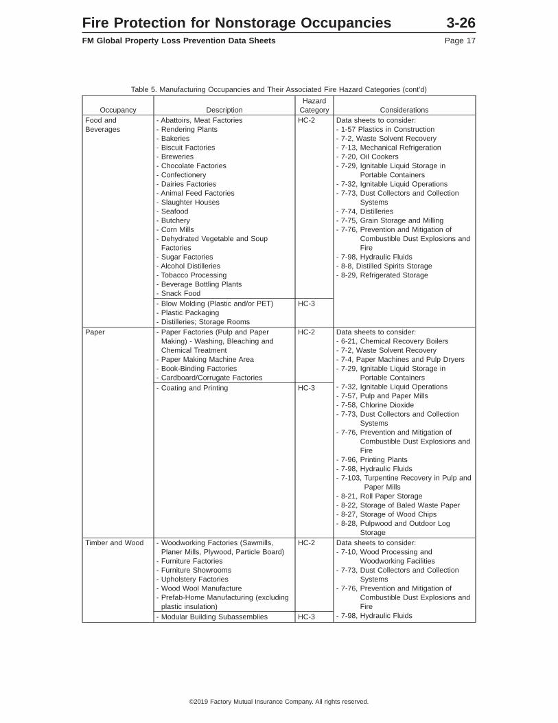
Table 5. Manufacturing Occupancies and Their Associated Fire Hazard Categories (cont’d)
Occupancy DescriptionHazard
Category ConsiderationsFood andBeverages
- Abattoirs, Meat Factories- Rendering Plants- Bakeries- Biscuit Factories- Breweries- Chocolate Factories- Confectionery- Dairies Factories- Animal Feed Factories- Slaughter Houses- Seafood- Butchery- Corn Mills- Dehydrated Vegetable and Soup
Factories- Sugar Factories- Alcohol Distilleries- Tobacco Processing- Beverage Bottling Plants- Snack Food
HC-2 Data sheets to consider:- 1-57 Plastics in Construction- 7-2, Waste Solvent Recovery- 7-13, Mechanical Refrigeration- 7-20, Oil Cookers- 7-29, Ignitable Liquid Storage in
Portable Containers- 7-32, Ignitable Liquid Operations- 7-73, Dust Collectors and Collection
Systems- 7-74, Distilleries- 7-75, Grain Storage and Milling- 7-76, Prevention and Mitigation of
Combustible Dust Explosions andFire
- 7-98, Hydraulic Fluids- 8-8, Distilled Spirits Storage- 8-29, Refrigerated Storage
- Blow Molding (Plastic and/or PET)- Plastic Packaging- Distilleries; Storage Rooms
HC-3
Paper - Paper Factories (Pulp and PaperMaking) - Washing, Bleaching andChemical Treatment
- Paper Making Machine Area- Book-Binding Factories- Cardboard/Corrugate Factories
HC-2 Data sheets to consider:- 6-21, Chemical Recovery Boilers- 7-2, Waste Solvent Recovery- 7-4, Paper Machines and Pulp Dryers- 7-29, Ignitable Liquid Storage in
Portable Containers- 7-32, Ignitable Liquid Operations- 7-57, Pulp and Paper Mills- 7-58, Chlorine Dioxide- 7-73, Dust Collectors and Collection
Systems- 7-76, Prevention and Mitigation of
Combustible Dust Explosions andFire
- 7-96, Printing Plants- 7-98, Hydraulic Fluids- 7-103, Turpentine Recovery in Pulp and
Paper Mills- 8-21, Roll Paper Storage- 8-22, Storage of Baled Waste Paper- 8-27, Storage of Wood Chips- 8-28, Pulpwood and Outdoor Log
Storage
- Coating and Printing HC-3
Timber and Wood - Woodworking Factories (Sawmills,Planer Mills, Plywood, Particle Board)
- Furniture Factories- Furniture Showrooms- Upholstery Factories- Wood Wool Manufacture- Prefab-Home Manufacturing (excluding
plastic insulation)
HC-2 Data sheets to consider:- 7-10, Wood Processing and
Woodworking Facilities- 7-73, Dust Collectors and Collection
Systems- 7-76, Prevention and Mitigation of
Combustible Dust Explosions andFire
- 7-98, Hydraulic Fluids- Modular Building Subassemblies HC-3
Fire Protection for Nonstorage Occupancies 3-26FM Global Property Loss Prevention Data Sheets Page 17
©2019 Factory Mutual Insurance Company. All rights reserved.
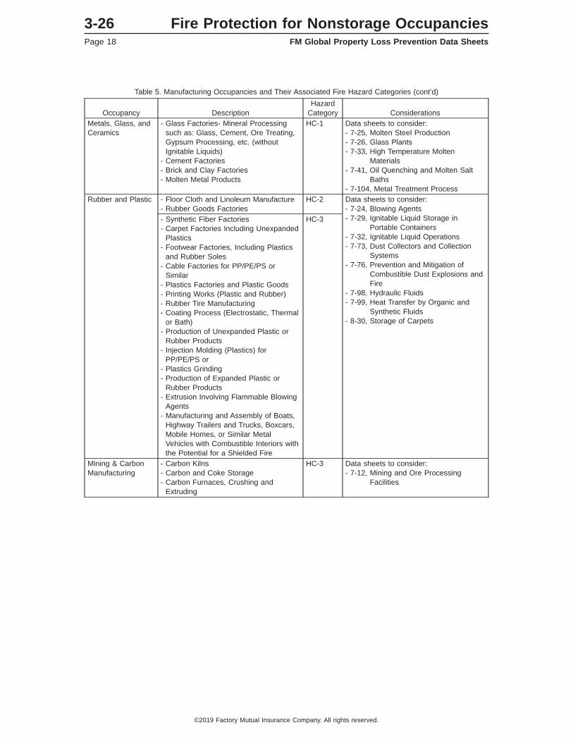
Table 5. Manufacturing Occupancies and Their Associated Fire Hazard Categories (cont’d)
Occupancy DescriptionHazard
Category ConsiderationsMetals, Glass, andCeramics
- Glass Factories- Mineral Processingsuch as: Glass, Cement, Ore Treating,Gypsum Processing, etc. (withoutIgnitable Liquids)
- Cement Factories- Brick and Clay Factories- Molten Metal Products
HC-1 Data sheets to consider:- 7-25, Molten Steel Production- 7-26, Glass Plants- 7-33, High Temperature Molten
Materials- 7-41, Oil Quenching and Molten Salt
Baths- 7-104, Metal Treatment Process
Rubber and Plastic - Floor Cloth and Linoleum Manufacture- Rubber Goods Factories
HC-2 Data sheets to consider:- 7-24, Blowing Agents- 7-29, Ignitable Liquid Storage in
Portable Containers- 7-32, Ignitable Liquid Operations- 7-73, Dust Collectors and Collection
Systems- 7-76, Prevention and Mitigation of
Combustible Dust Explosions andFire
- 7-98, Hydraulic Fluids- 7-99, Heat Transfer by Organic and
Synthetic Fluids- 8-30, Storage of Carpets
- Synthetic Fiber Factories- Carpet Factories Including Unexpanded
Plastics- Footwear Factories, Including Plastics
and Rubber Soles- Cable Factories for PP/PE/PS or
Similar- Plastics Factories and Plastic Goods- Printing Works (Plastic and Rubber)- Rubber Tire Manufacturing- Coating Process (Electrostatic, Thermal
or Bath)- Production of Unexpanded Plastic or
Rubber Products- Injection Molding (Plastics) for
PP/PE/PS or- Plastics Grinding- Production of Expanded Plastic or
Rubber Products- Extrusion Involving Flammable Blowing
Agents- Manufacturing and Assembly of Boats,
Highway Trailers and Trucks, Boxcars,Mobile Homes, or Similar MetalVehicles with Combustible Interiors withthe Potential for a Shielded Fire
HC-3
Mining & CarbonManufacturing
- Carbon Kilns- Carbon and Coke Storage- Carbon Furnaces, Crushing and
Extruding
HC-3 Data sheets to consider:- 7-12, Mining and Ore Processing
Facilities
3-26 Fire Protection for Nonstorage OccupanciesPage 18 FM Global Property Loss Prevention Data Sheets
©2019 Factory Mutual Insurance Company. All rights reserved.
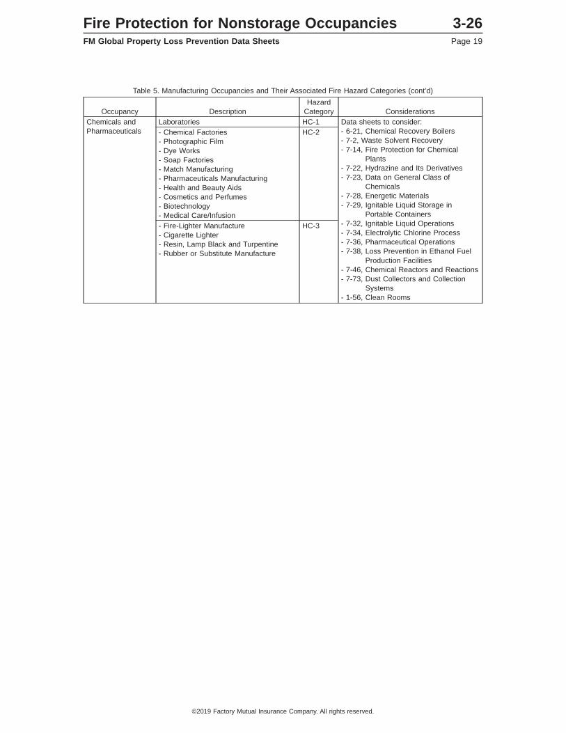
Table 5. Manufacturing Occupancies and Their Associated Fire Hazard Categories (cont’d)
Occupancy DescriptionHazard
Category ConsiderationsChemicals andPharmaceuticals
Laboratories HC-1 Data sheets to consider:- 6-21, Chemical Recovery Boilers- 7-2, Waste Solvent Recovery- 7-14, Fire Protection for Chemical
Plants- 7-22, Hydrazine and Its Derivatives- 7-23, Data on General Class of
Chemicals- 7-28, Energetic Materials- 7-29, Ignitable Liquid Storage in
Portable Containers- 7-32, Ignitable Liquid Operations- 7-34, Electrolytic Chlorine Process- 7-36, Pharmaceutical Operations- 7-38, Loss Prevention in Ethanol Fuel
Production Facilities- 7-46, Chemical Reactors and Reactions- 7-73, Dust Collectors and Collection
Systems- 1-56, Clean Rooms
- Chemical Factories- Photographic Film- Dye Works- Soap Factories- Match Manufacturing- Pharmaceuticals Manufacturing- Health and Beauty Aids- Cosmetics and Perfumes- Biotechnology- Medical Care/Infusion
HC-2
- Fire-Lighter Manufacture- Cigarette Lighter- Resin, Lamp Black and Turpentine- Rubber or Substitute Manufacture
HC-3
Fire Protection for Nonstorage Occupancies 3-26FM Global Property Loss Prevention Data Sheets Page 19
©2019 Factory Mutual Insurance Company. All rights reserved.
March 2010Interim Revision July 2019
Page 1 of 89
STORAGE OF CLASS 1, 2, 3, 4 AND PLASTIC COMMODITIES
Table of ContentsPage
1.0 SCOPE ................................................................................................................................................... 51.1 Changes ............................................................................................................................................ 51.2 Superseded Information .................................................................................................................... 51.3 How to Use This Data Sheet ........................................................................................................... 6
2.0 LOSS PREVENTION RECOMMENDATIONS ....................................................................................... 92.1 Construction and Location ............................................................................................................... 9
2.1.1 General .................................................................................................................................. 92.1.2 Steel Column Protection ....................................................................................................... 92.1.3 Heat and Smoke Venting and Draft Curtains ....................................................................... 9
2.1.3.1 Heat and Smoke Venting .......................................................................................... 92.1.3.2 Draft Curtains ............................................................................................................. 9
2.2 Occupancy ....................................................................................................................................... 92.2.1 General .................................................................................................................................. 92.2.2 Commodity Hazard .............................................................................................................. 102.2.3 Flue Spaces ........................................................................................................................ 10
2.2.3.1 Flue Spaces for Rack Storage Protected by Ceiling-Level Sprinklers Only ........... 102.2.3.2 Flue Spaces for Rack Storage Protected by both Ceiling-Level and In-RackSprinklers .............................................................................................................................. 10
2.2.3.3 Solid-Piled, Palletized, Shelf, and Bin-Box Storage ......................................................... 112.2.4 Pallets .................................................................................................................................. 112.2.5 Special Storage Considerations .......................................................................................... 11
2.2.5.1 Open-Top Containers Maintained in Storage Racks ............................................... 112.2.5.2 Portable Racks ........................................................................................................ 122.2.5.3 Movable Racks ........................................................................................................ 13
2.2.6 Clearance Between Top of Storage and Ceiling-Level Sprinkler Deflector ........................ 132.3 Protection ....................................................................................................................................... 13
2.3.1 General ................................................................................................................................ 132.3.2 Sprinkler System Types ....................................................................................................... 132.3.3 Ceiling-Level Storage Sprinklers ......................................................................................... 14
2.3.3.1 General ..................................................................................................................... 142.3.3.2 K-Factors, Nominal Temperature Rating, RTI Rating, and the Orientation of
Ceiling-Level Storage Sprinklers ............................................................................. 142.3.3.3 Spacing of Ceiling-Level Storage Sprinklers ........................................................... 152.3.3.4 Minimum Recommended Pressures for Ceiling-Level Storage Sprinklers ............. 152.3.3.5 Extension of Hydraulic Design ................................................................................ 152.3.3.6 Mixing Different Ceiling-Level Storage Sprinklers Within the Same Protected Area . 152.3.3.7 Ceiling-Level Sprinkler System Design Criteria ...................................................... 16
2.3.4 In-Rack Sprinklers (IRAS) ................................................................................................... 282.3.4.1 General ..................................................................................................................... 282.3.4.2 When In-Rack Sprinklers are Needed ..................................................................... 292.3.4.3 K-Factors, Nominal Temperature Rating, and RTI Rating of In-Rack Storage
Sprinklers ................................................................................................................. 312.3.4.4 In-Rack Sprinkler System Types ............................................................................. 312.3.4.5 General Guidelines for Positioning of In-Rack Sprinklers ....................................... 312.3.4.6 Horizontal Lay-Outs of In-Rack Sprinklers .............................................................. 312.3.4.7 Vertical Increments of In-Rack Sprinklers ............................................................... 44
FM GlobalProperty Loss Prevention Data Sheets 8-9
©2010-2019 Factory Mutual Insurance Company. All rights reserved. No part of this document may be reproduced,stored in a retrieval system, or transmitted, in whole or in part, in any form or by any means, electronic, mechanical,photocopying, recording, or otherwise, without written permission of Factory Mutual Insurance Company.

2.3.4.8 Design Guidelines for Ceiling-Level and In-Rack Sprinklers .................................. 462.3.4.9 Design Guidelines for Fire Protection Scheme 8-9A .............................................. 47
2.3.5 Hose Demands, Hose Connections, and System Duration ................................................ 522.3.5.1 Hose Demand and System Duration ...................................................................... 522.3.5.2 Hose Connections ................................................................................................... 53
2.3.6 Special Applications ............................................................................................................ 532.3.6.1 Ceiling-Only Sprinkler Protection for Class 1, 2 and 3 Commodities Protected by
Dry-Pipe and Similar Sprinkler Systems for Ceiling Heights Over 30 ft (9.0 m) ..... 532.3.6.2 Retail/Big-Box Warehouse Occupancies ................................................................. 562.3.6.3 Protection of Class 1, 2, 3, 4 and Cartoned Plastics in Open-Frame Single and
Double-Row Racks Using In-Rack Sprinklers Only in the Longitudinal Flue Space . 562.3.6.4 Protection of Class 1, 2, 3, 4, Cartoned Plastics and Uncartoned Unexpanded
Plastics in Single and Double-Row Racks Using a Combination of LongitudinalIn-Rack Sprinklers and Horizontal Barriers ............................................................... 57
2.3.6.5 Protection of Class 1, 2, 3, 4 and Unexpanded Plastics in Open-Frame StorageRacksUnder Ceilings up to 45 ft (13.5 m) High Using K14.0 (K200) and Larger,Quick-Response, Pendent Ceiling-level Sprinklers ................................................... 58
2.3.6.6 Alternative In-Rack Sprinkler Designs ....................................................................... 582.3.6.7 Retrofit In-Rack Sprinkler Protection Solution for Uncartoned Plastics Currently
Protected by In-Rack Sprinklers Only in the Longitudinal Flue Space Only ............ 622.3.6.8 K25.2EC (K360EC) Pendent In-Rack Sprinkler Protection of Class 1, 2, 3, 4 and
Cartoned Unexpanded Plastics in Open-Frame Racks in Combination withHorizontal Barriers ..................................................................................................... 65
2.3.6.9 Ceiling-Only Sprinkler Protection Recommendations for Ceiling Heights Over 45 ft(13.5 m) High ............................................................................................................. 68
3.0 SUPPORT FOR RECOMMENDATIONS ............................................................................................. 703.1 General .......................................................................................................................................... 703.2 Loss History ................................................................................................................................... 703.3 Illustrative Losses .......................................................................................................................... 71
3.3.1 Roll Cloth in Racks Obstruct Flue Spaces, Resulting in Extensive Fire and Water Damage . 713.3.2 Many Loss Prevention Principles Compromised in Warehouse Fire ................................. 713.3.3 Inadequate Sprinkler Protection Unable to Control Fire Involving Aisle Storage and
Racks with Solid Shelves .................................................................................................... 713.3.4 Fire in High Rack-Storage Controlled by In-Rack Sprinklers ............................................. 713.3.5 Lack of In-Rack Sprinklers for Racks With Solid Shelves Results in Extensive Fire
Damage ............................................................................................................................... 713.3.6 Open-Top Containers in Racks Interfere with Sprinkler Water Penetration
Resulting in Uncontrolled Fire ............................................................................................. 713.3.7 Poor Housekeeping Leads to Excessive Fire Spread ........................................................ 723.3.8 Strong Water Supply Overcomes Plugged Sprinklers ........................................................ 72
4.0 REFERENCES ..................................................................................................................................... 724.1 FM Global ....................................................................................................................................... 72
APPENDIX A GLOSSARY OF TERMS ..................................................................................................... 72APPENDIX B DOCUMENT REVISION HISTORY ...................................................................................... 83
List of FiguresFig. 1. Flowchart for determining the protection options for solid-piled, palletized, shelf, and bin-box
storage arrangements ........................................................................................................................ 7Fig. 2. Flowchart for determining the protection options available for rack storage arrangements ............. 8Fig. 3. Flowchart for evaluating the need for in-rack sprinklers .................................................................. 30Fig. 4. Recommended horizontal in-rack sprinkler arrangements for single-row racks .............................. 33Fig. 5. Recommended horizontal in-rack sprinkler arrangements for double-row racks ............................ 34Fig. 6. Recommended horizontal IRAS(E) in-rack sprinkler arrangements for double-row racks .............. 35Fig. 7. Recommended horizontal in-rack sprinkler arrangements for multiple-row racks ........................... 36Fig. 8. Plan view of IRAS(EO) in-rack sprinkler arrangement for single-row racks .................................... 37Fig. 9. Plan view of IRAS(EO) in-rack sprinkler arrangement for double-row racks .................................. 38Fig. 10. Plan view of IRAS(EO) in-rack sprinkler arrangement for multiple-row racks ............................... 39
8-9 Storage of Class 1, 2, 3, 4 and Plastic CommoditiesPage 2 FM Global Property Loss Prevention Data Sheets
©2010-2019 Factory Mutual Insurance Company. All rights reserved.
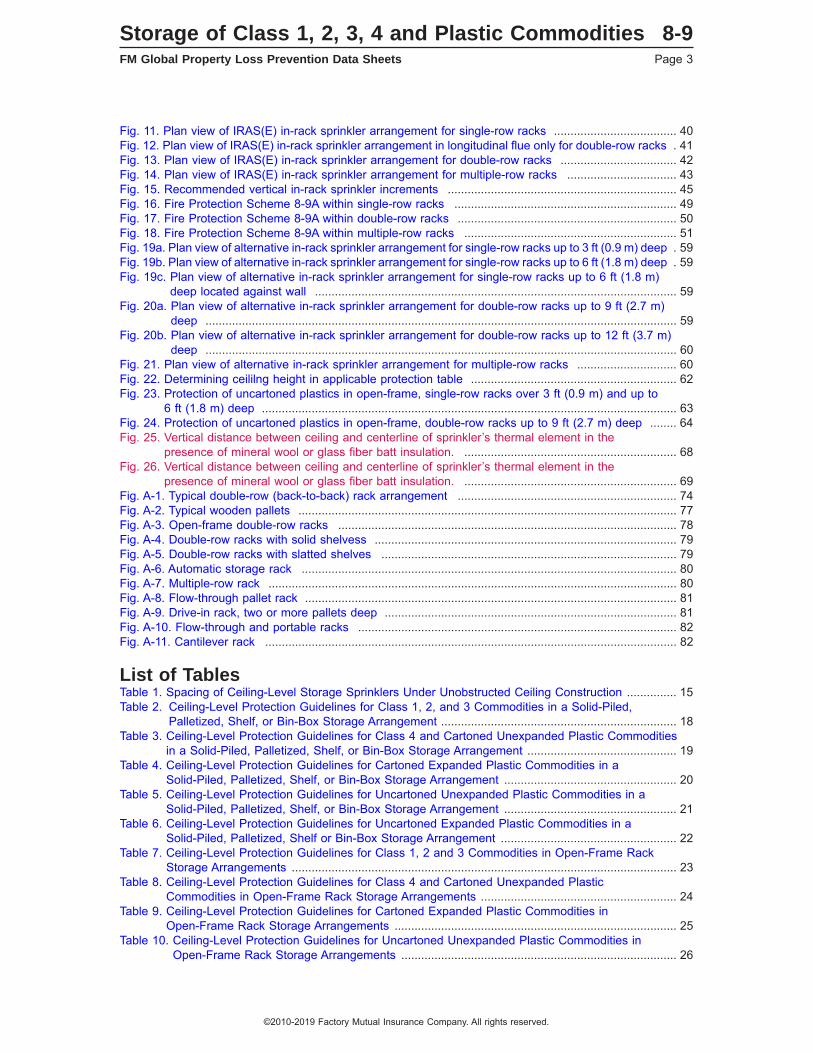
Fig. 11. Plan view of IRAS(E) in-rack sprinkler arrangement for single-row racks ..................................... 40Fig. 12. Plan view of IRAS(E) in-rack sprinkler arrangement in longitudinal flue only for double-row racks . 41Fig. 13. Plan view of IRAS(E) in-rack sprinkler arrangement for double-row racks ................................... 42Fig. 14. Plan view of IRAS(E) in-rack sprinkler arrangement for multiple-row racks ................................. 43Fig. 15. Recommended vertical in-rack sprinkler increments ..................................................................... 45Fig. 16. Fire Protection Scheme 8-9A within single-row racks ................................................................... 49Fig. 17. Fire Protection Scheme 8-9A within double-row racks .................................................................. 50Fig. 18. Fire Protection Scheme 8-9A within multiple-row racks ................................................................ 51Fig. 19a. Plan view of alternative in-rack sprinkler arrangement for single-row racks up to 3 ft (0.9 m) deep . 59Fig. 19b. Plan view of alternative in-rack sprinkler arrangement for single-row racks up to 6 ft (1.8 m) deep . 59Fig. 19c. Plan view of alternative in-rack sprinkler arrangement for single-row racks up to 6 ft (1.8 m)
deep located against wall ............................................................................................................. 59Fig. 20a. Plan view of alternative in-rack sprinkler arrangement for double-row racks up to 9 ft (2.7 m)
deep .............................................................................................................................................. 59Fig. 20b. Plan view of alternative in-rack sprinkler arrangement for double-row racks up to 12 ft (3.7 m)
deep .............................................................................................................................................. 60Fig. 21. Plan view of alternative in-rack sprinkler arrangement for multiple-row racks .............................. 60Fig. 22. Determining ceililng height in applicable protection table .............................................................. 62Fig. 23. Protection of uncartoned plastics in open-frame, single-row racks over 3 ft (0.9 m) and up to
6 ft (1.8 m) deep ............................................................................................................................. 63Fig. 24. Protection of uncartoned plastics in open-frame, double-row racks up to 9 ft (2.7 m) deep ........ 64Fig. 25. Vertical distance between ceiling and centerline of sprinkler’s thermal element in the
presence of mineral wool or glass fiber batt insulation. ................................................................ 68Fig. 26. Vertical distance between ceiling and centerline of sprinkler’s thermal element in the
presence of mineral wool or glass fiber batt insulation. ................................................................ 69Fig. A-1. Typical double-row (back-to-back) rack arrangement .................................................................. 74Fig. A-2. Typical wooden pallets .................................................................................................................. 77Fig. A-3. Open-frame double-row racks ...................................................................................................... 78Fig. A-4. Double-row racks with solid shelvess ........................................................................................... 79Fig. A-5. Double-row racks with slatted shelves ......................................................................................... 79Fig. A-6. Automatic storage rack ................................................................................................................. 80Fig. A-7. Multiple-row rack ........................................................................................................................... 80Fig. A-8. Flow-through pallet rack ................................................................................................................ 81Fig. A-9. Drive-in rack, two or more pallets deep ........................................................................................ 81Fig. A-10. Flow-through and portable racks ................................................................................................ 82Fig. A-11. Cantilever rack ............................................................................................................................ 82
List of TablesTable 1. Spacing of Ceiling-Level Storage Sprinklers Under Unobstructed Ceiling Construction ............... 15Table 2. Ceiling-Level Protection Guidelines for Class 1, 2, and 3 Commodities in a Solid-Piled,
Palletized, Shelf, or Bin-Box Storage Arrangement ....................................................................... 18Table 3. Ceiling-Level Protection Guidelines for Class 4 and Cartoned Unexpanded Plastic Commodities
in a Solid-Piled, Palletized, Shelf, or Bin-Box Storage Arrangement ............................................. 19Table 4. Ceiling-Level Protection Guidelines for Cartoned Expanded Plastic Commodities in a
Solid-Piled, Palletized, Shelf, or Bin-Box Storage Arrangement .................................................... 20Table 5. Ceiling-Level Protection Guidelines for Uncartoned Unexpanded Plastic Commodities in a
Solid-Piled, Palletized, Shelf, or Bin-Box Storage Arrangement .................................................... 21Table 6. Ceiling-Level Protection Guidelines for Uncartoned Expanded Plastic Commodities in a
Solid-Piled, Palletized, Shelf or Bin-Box Storage Arrangement ..................................................... 22Table 7. Ceiling-Level Protection Guidelines for Class 1, 2 and 3 Commodities in Open-Frame Rack
Storage Arrangements .................................................................................................................... 23Table 8. Ceiling-Level Protection Guidelines for Class 4 and Cartoned Unexpanded Plastic
Commodities in Open-Frame Rack Storage Arrangements ........................................................... 24Table 9. Ceiling-Level Protection Guidelines for Cartoned Expanded Plastic Commodities in
Open-Frame Rack Storage Arrangements ..................................................................................... 25Table 10. Ceiling-Level Protection Guidelines for Uncartoned Unexpanded Plastic Commodities in
Open-Frame Rack Storage Arrangements ................................................................................... 26
Storage of Class 1, 2, 3, 4 and Plastic Commodities 8-9FM Global Property Loss Prevention Data Sheets Page 3
©2010-2019 Factory Mutual Insurance Company. All rights reserved.

Table 11. Ceiling-Level Protection Guidelines for Uncartoned Expanded Plastic Commodities inOpen-Frame Rack Storage Arrangements ................................................................................... 27
Table 12. Hydraulic Design for In-Rack Sprinkler Systems ........................................................................ 46Table 13. Hydraulic Design for Ceiling-Level Sprinkler Systems Supplemented with In-Rack Sprinklers .. 47Table 14. Hose Demand and Water Supply Duration Design Guidelines .................................................... 53Table 14a. Ceiling-Level Sprinkler System Designs for Class 1 and 2 Commodities Protected by
Dry-Pipe and Similar Sprinkler Systems ..................................................................................... 54Table 14b. Ceiling-Level Sprinkler System Designs for Class 3 Commodities Protected by Dry-Pipe
and Similar Sprinkler Systems .................................................................................................... 55Table 15. Number of Sprinklers in the In-Rack Design ................................................................................ 61Table 16. Minimum Flow in the In-Rack Design .......................................................................................... 61Table 17. Number of Face In-Rack Sprinklers in the Retrofit In-Rack Design ............................................ 65Table 17a. Minimum Number of K25.2EC (K360EC) Pendent In-Rack Sprinklers Included in the
In-Rack Sprinkler Design ............................................................................................................ 67Table 17b. Ceiling-Only Sprinkler Designs for Ceiling Heights up to 50 ft (15.0 m) .................................... 69Table 18. Relationship Between the Number of Sprinklers that Operate During a Storage Fire and Fire
Control ........................................................................................................................................... 70
8-9 Storage of Class 1, 2, 3, 4 and Plastic CommoditiesPage 4 FM Global Property Loss Prevention Data Sheets
©2010-2019 Factory Mutual Insurance Company. All rights reserved.

1.0 SCOPE
This property loss prevention data sheet provides fire protection recommendations for the storage of Class1, 2, 3, 4, and plastic commodities maintained in rack, solid-piled, palletized, shelf, or bin-box storagearrangements. Apply this data sheet when (1) Class 1, 2 or 3 commodities are stored higher than 10 ft(3.0 m), (2) Class 4 or plastic commodities are stored higher than 5 ft (1.5 m), or (3) storage of any heightoccupies an area, as defined by minimum 8 ft (2.4 m) wide aisles, greater than 200 ft2 (20 m2). Use theapplicable occupancy-specific data sheet (see Appendix A) when storage consists of commodity hazardsother than Class 1, 2, 3, 4 or plastics.
See Data Sheet 8-1, Commodity Classification, for guidelines on how to classify individual commodities;see Section 2.2.2 for information on how to determine an overall commodity rating for a given storage area.
Refer to FM Global Data Sheet 2-0, Installation Guidelines for Automatic Sprinklers, for installation guidelinesfor the sprinklers listed in this data sheet, as well as their compatibility with the facility’s construction features.
The recommendations in Data Sheet 8-9 are intended for the design of new automatic sprinkler systems, orexisting systems that are to be modified. To evaluate existing automatic sprinkler systems, or to determinewhether new protection options based on recently FM Approved products and/or fire testing are a viable optionto help lower their risk of loss, clients of FM Global can contact their local FM Global servicing office.
The fire protection recommendations in this data sheet are based on the results of full-scale fire testing, lossexperience, and/or engineering judgment. Not every storage arrangement or protection option has beentested, nor has every potential solution been identified. If FM Global data sheets exist that address the specificoccupancy, refer to those data sheets for further guidance.
Refer to the applicable occupancy-specific data sheet (see Appendix A for definition) for loss preventionrecommendations related to the following subjects, which are not covered in this data sheet:
• Special hazards, such as the storage of flammable gases, flammable liquids, and flammable solids (usuallyfound in 7-series data sheets)
• Commodities such as rubber tires, baled fiber, hanging garments, roll paper, baled waste paper, rollednon-woven fabrics, pallets, and carpets (usually found in 8-series data sheets)
• Storage arrangements, such as carousel storage or automatic storage storage and retrieval systems,containing high-value equipment (usually found 8-series data sheets)
Before selecting one of the protection options in this data sheet for either a new building or a building beingretrofitted with a new protection system, consider possible future changes in storage arrangements, availablewater supplies, and/or commodity hazards. Also consider the susceptibility of the occupancy to nonthermaldamage. If ceiling-only protection options are available, consider protecting to the highest commodity hazardthat the ceiling height and the available water supply will allow in order to provide as much flexibility aspossible for future changes in occupancy or water supply.
Note that the metric (SI) equivalent values in this data sheet are not based on strict mathematical conversion,but on design-desired values.
1.1 Changes
July 2019. Interim revision. A new Section 2.3.6.9 has been created to address the installation and designguidelines for ceiling-only protection options involving ceiling heights of 50 ft (15 m) and 55 ft (16.5 m).
1.2 Superseded Information
This data sheet incorporates and supersedes the following engineering bulletins:
• 06-11, Tyco Model TY9128, K25.2EC (K360EC), Upright Storage Sprinkler under Ceiling over 30 ft (9.0m) and up to 35 ft (10.5 m) High
• 07-12, Viking Model VK502, Quick-Response, K14.0 (K200), Dry-Pendent Sprinkler
Storage of Class 1, 2, 3, 4 and Plastic Commodities 8-9FM Global Property Loss Prevention Data Sheets Page 5
©2010-2019 Factory Mutual Insurance Company. All rights reserved.
1.3 How to Use This Data Sheet
As with any FM Global data sheet, a complete and comprehensive understanding of the information in thisdocument can only be achieved by a thorough review of its content. To assist with the proper use of thisdata sheet, however, two flowcharts have been created. The first flowchart (Figure 1) represents the processfor determining the proper design of an automatic sprinkler system that is intended to protect solid-piled,palletized, shelf, or bin-box storage arrangements. The second flowchart (Figure 2) represents the processfor determining the proper design of an automatic sprinkler system that is intended to protect rack storage.
Use these two flowcharts in combination with the text of this data sheet to determine all possible protectionoptions.
8-9 Storage of Class 1, 2, 3, 4 and Plastic CommoditiesPage 6 FM Global Property Loss Prevention Data Sheets
©2010-2019 Factory Mutual Insurance Company. All rights reserved.
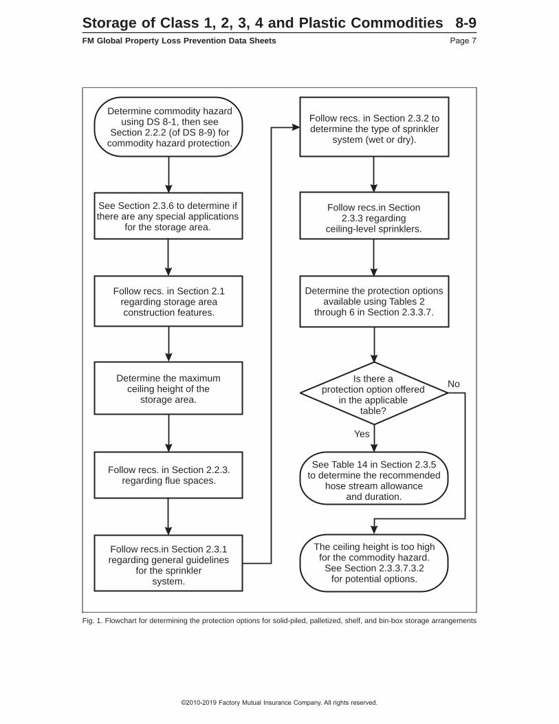
Fig. 1. Flowchart for determining the protection options for solid-piled, palletized, shelf, and bin-box storage arrangements
Determine commodity hazardusing DS 8-1, then see
Section 2.2.2 (of DS 8-9) forcommodity hazard protection.
See Section 2.3.6 to determine ifthere are any special applications
for the storage area.
Follow recs.in Section2.3.3 regarding
ceiling-level sprinklers.
Follow recs. in Section 2.3.2 todetermine the type of sprinkler
system (wet or dry).
Determine the protection optionsavailable using Tables 2
through 6 in Section 2.3.3.7.
Is there aprotection option offered
in the applicabletable?
No
Yes
See Table 14 in Section 2.3.5to determine the recommended
hose stream allowanceand duration.
The ceiling height is too highfor the commodity hazard.
See Section 2.3.3.7.3.2for potential options.
Follow recs. in Section 2.1regarding storage areaconstruction features.
Follow recs. in Section 2.2.3.regarding flue spaces.
Follow recs.in Section 2.3.1regarding general guidelines
for the sprinklersystem.
Determine the maximumceiling height of the
storage area.
Storage of Class 1, 2, 3, 4 and Plastic Commodities 8-9FM Global Property Loss Prevention Data Sheets Page 7
©2010-2019 Factory Mutual Insurance Company. All rights reserved.
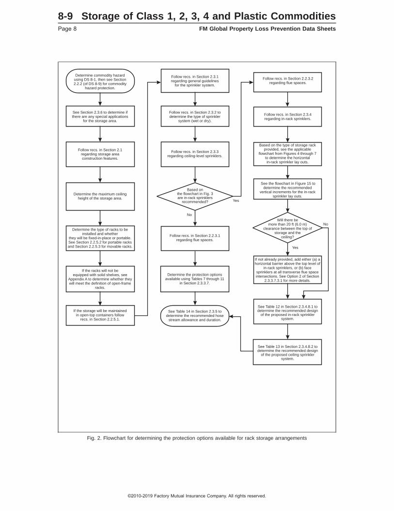
Fig. 2. Flowchart for determining the protection options available for rack storage arrangements
Determine commodity hazardusing DS 8-1, then see Section2.2.2 (of DS 8-9) for commodity
hazard protection.
See Section 2.3.6 to determine ifthere are any special applications
for the storage area.
Follow recs. in Section 2.3.3regarding ceiling-level sprinklers.
Follow recs. in Section 2.2.3.1regarding flue spaces.
If not already provided, add either (a) ahorizontal barrier above the top level of
in-rack sprinklers, or (b) facesprinklers at all transverse flue spaceintersections. See Option 2 of Section
2.3.3.7.3.1 for more details.
Follow recs. in Section 2.3.1regarding general guidelines
for the sprinkler system.
Follow recs. in Section 2.3.2 todetermine the type of sprinkler
system (wet or dry).
Based on the type of storage rackprovided, see the applicable
flowchart from Figures 4 through 7to determine the horizontalin-rack sprinkler lay outs.
See the flowchart in Figure 15 todetermine the recommended
vertical increments for the in-racksprinkler lay outs.
Will there bemore than 20 ft (6.0 m)
clearance between the top ofstorage and the
ceiling?
Based onthe flowchart in Fig. 3are in-rack sprinklers
recommended?
See Table 12 in Section 2.3.4.8.1 todetermine the recommended design
of the proposed in-rack sprinklersystem.
See Table 13 in Section 2.3.4.8.2 todetermine the recommended design
of the proposed ceiling sprinklersystem.
Determine the protection optionsavailable using Tables 7 through 11
in Section 2.3.3.7.
No
No
Yes
Yes
See Table 14 in Section 2.3.5 todetermine the recommended hose
stream allowance and duration.
Follow recs. in Section 2.3.4regarding in-rack sprinklers.
Follow recs. in Section 2.2.3.2regarding flue spaces.
Follow recs. in Section 2.1regarding storage areaconstruction features.
Determine the type of racks to beinstalled and whether
they will be fixed-in-place or portable.See Section 2.2.5.2 for portable racksand Section 2.2.5.3 for movable racks.
If the racks will not beequipped with solid shelves, see
Appendix A to determine whether theywill meet the definition of open-frame
racks.
If the storage will be maintainedin open-top containers follow
recs. in Section 2.2.5.1.
Determine the maximum ceilingheight of the storage area.
8-9 Storage of Class 1, 2, 3, 4 and Plastic CommoditiesPage 8 FM Global Property Loss Prevention Data Sheets
©2010-2019 Factory Mutual Insurance Company. All rights reserved.
2.0 LOSS PREVENTION RECOMMENDATIONS
2.1 Construction and Location
2.1.1 General
2.1.1.1 Construct storage facilities in accordance with the relevant FM Global property loss prevention datasheets. See the 1-series data sheets for guidelines relevant to the construction features of most storagefacilities.
2.1.1.2 Adhere to the recommendations in the relevant data sheet to ensure the construction features ofthe facility are compatible with the Storage sprinkler being used.
2.1.1.3 Properly anchor all rack storage structures to prevent them from falling over and, in turn, causingnearby racks to fall over (i.e., creating a “domino” effect). Take into consideration the effects of rack loads,the additional load created by the collection or absorption of fire protection water by the stored commodity, theweight of water-filled, in-rack sprinkler piping (if provided), and any seismic conditions (see Data Sheet 1-2,Earthquakes).
2.1.1.4 Design rack-supported structures taking into consideration the effects of weather (wind, snow, rain,hail, etc.), rack loads, seismic conditions (see Data Sheet 1-2, Earthquakes), and the additional load createdby the collection or absorption of fire protection water by the stored commodity, the weight of water-filledsprinkler piping (from ceiling or in-rack sprinklers), and any other loads to which the rack or structure maybe exposed. Account for additional weight created by the absorption of sprinkler water by corrugatedcontainers. Assume a value of 0.012 lb (5.44 g) per 1 ft3 (0.028 m3) and apply this value to the overall volumeof the pallet load. If open-top containers are present, assume roughly one-third of the containers storedvertically will be filled with water, but the other two-thirds of containers will be completely consumed duringa fire event.
2.1.2 Steel Column Protection
Adhering to the design guidelines in this data sheet eliminates the need for both building column and overheadsteel protection.
2.1.3 Heat and Smoke Venting and Draft Curtains
2.1.3.1 Heat and Smoke Venting
See Data Sheet 2-0, Installation Guidelines for Automatic Sprinklers, for recommendations related to theuse of heat and smoke venting in the presence of Storage sprinklers.
2.1.3.2 Draft Curtains
See Data Sheet 2-0, Installation Guidelines for Automatic Sprinklers, for recommendations related to theuse of draft curtains in the presence of Storage sprinklers.
2.2 Occupancy
2.2.1 General
Storage arrangements vary among locations. In general, most storage arrangements can be classified assolid-piled, palletized, shelf, bin-box, or single-row, double-row, or multiple-row racks for the purpose ofdetermining fire protection requirements. Within this data sheet the design guidelines for solid-piled, palletized,shelf, or bin-box storage arrangements are consolidated into the same table for a given commodity hazard.Similarly, the design guidelines for single-row, double-row, and multiple-row storage racks are consolidatedinto the same table for a given commodity hazard.
2.2.1.1 For storage that will be maintained directly on the floor, refer to Data Sheet 1-24, Protection AgainstLiquid Damage, to minimize the exposure from sprinkler water discharge or other potential liquid releases.
Storage of Class 1, 2, 3, 4 and Plastic Commodities 8-9FM Global Property Loss Prevention Data Sheets Page 9
©2010-2019 Factory Mutual Insurance Company. All rights reserved.

2.2.2 Commodity Hazard
2.2.2.1 Use Data Sheet 8-1, Commodity Classification, to determine the types of commodity hazards locatedwithin a given storage area.
2.2.2.2 Base the protection for the storage area on the most severe commodity hazard present anywherewithin that storage area. The commodity hazards for this data sheet are generally ranked from lowest hazard(Class 1) to highest hazard (uncartoned expanded plastic) as follows:
Class 1Class 2Class 3Class 4Cartoned Unexpanded PlasticCartoned Expanded PlasticUncartoned Unexpanded PlasticUncartoned Expanded Plastic
The ranking above applies for rack storage because the stability of storage that is provided by the rackstructure. The ranking outlined above may be somewhat different when maintained in a solid-piled orpalletized arrangement as storage instability can impact the protection required.
2.2.2.3 See Section 2.3.4.9 regarding Scheme 8-9A if the most severe commodity hazard exists in relativelysmall amounts throughout the storage area and protecting it creates a challenge.
2.2.3 Flue Spaces
Flue spaces within storage configurations that are arranged as outlined in this data sheet will promptly ventheat from a fire vertically. This allows for (1) the sprinklers to operate as quickly as possible, and (2) reducedhorizontal fire spread within the storage array. Flue spaces arranged as outlined in this data sheet will alsoallow sprinkler water penetration down through the storage arrangement. Without sufficient water penetrationto burning commodities throughout the storage array, fire control may not be achieved.
2.2.3.1 Flue Spaces for Rack Storage Protected by Ceiling-Level Sprinklers Only
2.2.3.1.1 Maintain all transverse flue spaces at a minimum net width of 3 in. (75 mm) throughout the verticalheight of the rack. Provide transverse flue spaces a maximum of every 4-1⁄2 ft (1.4 m) horizontally when theirnet width is less than 6 in. (150 mm) or when their vertical alignment cannot be maintained. The maximumhorizontal distance between well-maintained, vertically aligned transverse flue spaces can be increased to 9ft (2.7 m) when their net width is 6 in. (150 mm) or greater.
2.2.3.1.2 Longitudinal flue spaces are not required in double-row racks; however, if they are provided, maintaina minimum net width of 3 in. (75 mm) throughout the vertical height of the rack. Provide net 6 in. (150 mm)wide longitudinal flue spaces within multiple-row racks a maximum of every 16 ft (4.8 m) horizontally.
2.2.3.1.3 Ensure rolled or similar types of commodities stored in racks are arranged so they cannot bulgeinto or encroach over flue spaces. If adequate flue spaces are difficult to maintain (e.g., loading of racksbecomes haphazard during peak production), provide wire mesh and/or other physical means to ensureadequate flue spaces are always maintained.
2.2.3.1.4 Treat storage racks not having flue spaces as described in Sections 2.2.3.1.1 through 2.2.3.1.3as racks with solid shelves. Base the size of the shelf area on the presence of well-maintained, verticallyaligned flue spaces having a minimum net width of 3 in. (75 mm). If well-maintained, vertically aligned fluespaces having a minimum net width of 3 in. (75 mm) cannot be provided, protect the racks based on thepresence of solid shelves greater than 64 ft2 (6.0 m2) in area.
2.2.3.2 Flue Spaces for Rack Storage Protected by both Ceiling-Level and In-Rack Sprinklers
2.2.3.2.1 Maintain all transverse flue spaces at a minimum net width of 3 in. (75 mm) throughout the verticalheight of the rack. However, transverse flue spaces are not required (1) for the storage tier located directlyabove in-rack sprinklers, or (2) when in-rack sprinklers are provided at every tier level.
8-9 Storage of Class 1, 2, 3, 4 and Plastic CommoditiesPage 10 FM Global Property Loss Prevention Data Sheets
©2010-2019 Factory Mutual Insurance Company. All rights reserved.
2.2.3.2.2 Longitudinal flue spaces are not required in double-row racks; however, if they are provided, maintaina minimum net width of 3 in. (75 mm) throughout the vertical height of the rack. Longitudinal flue spacesare not required (1) for the storage tier located directly above in-rack sprinklers, or (2) when in-rack sprinklersare provided at every tier level.
2.2.3.2.3 Arrange rolled or similar types of commodities stored in racks so they cannot bulge into or encroachover flue spaces located directly below in-rack sprinklers. The exception to this is storage located directlyabove a level of in-rack sprinklers. If adequate flue spaces are difficult to maintain (e.g., loading of racksbecomes haphazard during peak production), provide wire mesh and/or other physical means to ensureadequate flue spaces are always maintained.
2.2.3.2.4 Treat storage racks not having flue spaces as described above in Sections 2.2.3.2.1 through2.2.3.2.3 as racks with solid shelves greater than 64 ft2 (6.0 m2) in area.
2.2.3.3 Solid-Piled, Palletized, Shelf, and Bin-Box Storage
There are no recommendations regarding the minimum size and horizontal distance between flue spacesfor this type of storage; however, arrange storage such that flue spaces that are provided are not blocked fromwater penetration.
2.2.4 Pallets
2.2.4.1 Use noncombustible or metal pallets whenever possible.
2.2.4.2 Include the combustibility of pallets in the overall commodity classification. Refer to Data Sheet 8-1,Commodity Classification, for a description of how this can be accomplished.
2.2.4.3 Protect the storage of idle pallets in accordance with the recommendations in Data Sheet 8-24, IdlePallet Storage.
2.2.5 Special Storage Considerations
2.2.5.1 Open-Top Containers Maintained in Storage Racks
Open-top containers will collect sprinkler water, keeping it from running across the top of storage and downthe flues. This will prevent water penetration to the fire in the lower levels where it is needed thus resultingin inadequate fire protection. Rack collapse may also occur if too much water is collected See Section2.2.5.1.1 when open-top noncombustible containers are present within rack storage, or Section 2.2.5.1.2when open-top combustible containers are present within rack storage.
2.2.5.1.1 Protect storage racks containing open-top noncombustible containers per Sections 2.2.5.1.3 or2.2.5.1.4 unless one of the following exceptions is met:
1) All of the storage located below the open-top noncombustible containers is either noncombustible orin noncombustible containers.
2) All of the open-top noncombustible containers are located on the bottom tier of the storage rack.
3) The open-top containers are designed to vent water into the transverse flue space, or uniformly aroundthe container, with minimal water collection (maximum ½ in. [13 mm]) within the container. This cantypically be accomplished by providing a minimum 30 percent venting area along the perimeter of thecontainer. For this option to apply, storage within the container cannot be water absorbent nor be capableof blocking water from discharging through the container’s vented area.
2.2.5.1.2 Protect storage racks containing open-top combustible containers per Sections 2.2.5.1.3 or 2.2.5.1.4unless one of the following exceptions is met:
1) All of the open-top combustible containers are located on the bottom tier of the storage rack. Note, ifthe open-top containers are a higher commodity hazard than the storage located in the tier levels abovethem, then this option is only applicable if the sprinkler protection is capable of adequately protecting thesecontainers as if they were closed-top and stored throughout the entire height of the rack.
2) The open-top containers are designed to vent water into the transverse flue space, or uniformly aroundthe container, with minimal water collection (maximum ½ in. [13 mm]) within the container. This cantypically be accomplished by providing a minimum 30 percent venting area along the perimeter of the
Storage of Class 1, 2, 3, 4 and Plastic Commodities 8-9FM Global Property Loss Prevention Data Sheets Page 11
©2010-2019 Factory Mutual Insurance Company. All rights reserved.
container. For this option to apply, storage within the container cannot be water absorbent nor be capableof blocking water from discharging through the container’s vented area.
2.2.5.1.3 When the open-top container hazard is not addressed in accordance with Sections 2.2.5.1.1 or2.2.5.1.2 and the storage racks are either open-frame or have solid shelves up to 64 ft2 (6.0 m2) in area,provide sprinkler protection for the racks as though 20 to 64 ft2 (2.0 to 6.0 m2) solid shelves are present. Inaddition, at least one level of in-rack sprinklers is needed for any storage in excess of 10 ft (3.0 m) high.Install in-rack sprinklers in accordance with Figure 11 for single-row racks, Figure 13 for double-row racks,or Figure 14 for multiple-row racks at the vertical tier heights where in-rack sprinklers are recommended perSection 2.3.4.7.
2.2.5.1.3.1 For double-row racks, the horizontal distance between face sprinklers can be increased to 10 ft(3.0 m) when (1) there is only a single transverse flue space between face sprinklers, and (2) all transverseflue spaces are vertically aligned.
2.2.5.1.3.2 For multiple-row racks, the horizontal in-rack sprinkler arrangement can be in accordance withFigure 10 when (1) there is only a single flue space between in-rack sprinklers, and (2) all flue spaces arevertically aligned.
2.2.5.1.4 When the open-top container hazard is not addressed in accordance with Sections 2.2.5.1.1 or2.2.5.1.2 and the storage racks have solid shelves greater than 64 ft2 (6.0 m2) in area, protect the rack storagebased on presence of solid shelves greater than 64 ft2 (6.0 m2) in area and install in-rack sprinklers inaccordance with Figure 11 for single-row racks, Figure 13 for double-row racks, or Figure 14 for multiple-rowracks.
2.2.5.1.4.1 For double-row racks, the horizontal distance between face sprinklers can be increased to 10 ft(3.0 m) when (1) there is only a single transverse flue space between the face sprinklers, and (2) solidshelves greater than 64 ft2 (6.0 m2) in area are at all tier levels, or all of the tier levels without solid shelvesthat are located below the tier level with solid shelves have transverse flue spaces that are vertically aligned.
2.2.5.1.4.2 For multiple-row racks, the horizontal in-rack sprinkler arrangement can be in accordance withFigure 10 when (1) there is only a single transverse flue space between in-rack sprinklers, and (2) solidshelves greater than 64 ft2 (6.0 m2) in area are at all tier levels, or all of the tier levels without solid shelvesthat are located below the tier level with solid shelves have flue spaces that are vertically aligned.
2.2.5.2 Portable Racks
Portable racks are designed to be transported with fork-lift trucks. They are typically found to have wire meshsiding with solid bottoms; however, they can be arranged in various configurations of solid or non-solid sidesand bottoms. Commodity stored in portable racks burn differently than cartoned commodities maintainedin storage racks, as the initial fire within a portable rack does not involve a surface fire on the outside of acardboard box, but rather the actual commodity stored inside the portable rack. This generally results in amore challenging fire when compared to fires in open-frame storage racks.
If the portable racks are not provided with proper flue spaces between them (or with another means of allowingheat from a fire to vent vertically while at the same time water from sprinklers to penetrate down throughthem), fire control will not be possible.
2.2.5.2.1 Portable racks with bottoms at least 70% open: Treat as open-frame rack storage as long as thestorage within the portable rack (1) allows heat from a fire to vent vertically up through the portable rack, and(2) allows water to penetrate down through the portable rack, and (3) does not absorb water. Otherwise,treat the portable rack as having a solid bottom.
2.2.5.2.2 Portable racks with solid bottoms or bottoms less than 70% open: Limit the footprint size of a portablerack to a maximum of 20 ft2 (2.0 m2) and provide minimum 3 in. (75 mm) wide flue spaces around all sidesof the portable rack. Protect such a portable rack arrangement in accordance with the guidelines foropen-frame rack storage as outlined in Section 2.3.3.7. As an alternative, limit the footprint size of a portablerack to a maximum of 40 ft2 (4.0 m2) and equip the portable rack with three full-height, fixed-in-place, solidwooden or noncombustible sides that will inhibit horizontal fire spread. Protect such a portable rackarrangement in accordance with the guidelines for solid-piled storage as outlined in Section 2.3.3.7.
2.2.5.2.3 Treat portable racks that do not meet the guidelines in Sections 2.2.5.2.1 or 2.2.5.2.2 as rack storagehaving solid shelves. Size the shelf area using the guidelines for rack storage.
8-9 Storage of Class 1, 2, 3, 4 and Plastic CommoditiesPage 12 FM Global Property Loss Prevention Data Sheets
©2010-2019 Factory Mutual Insurance Company. All rights reserved.

2.2.5.2.4 If ceiling-only protection options are not available from the applicable protection table, then limitthe storage area of the portable racks to a maximum of 100 ft2 (9.3 m2), as defined by a minimum 8 ft (2.4m) wide clear space on all sides of the storage area, and limit the storage height to a maximum of 10 ft (3.0m) for cartoned commodities or 5 ft (1.5 m) if the commodity hazard is uncartoned plastics. Base the automaticsprinkler system design requirements on the occupancy surrounding the portable storage instead of theportable storage itself.
2.2.5.3 Movable Racks
Movable racks are designed to use as much of the available storage space as possible. Usually, racks areon tracks and are butted against one another in the aisle-face direction. Loading and unloading takes placein the aisle that is open. Loaded racks are located on one or both sides of the aisles, and empty racks maybe located anywhere.
2.2.5.3.1 Protect rack storage in movable racks as multiple-row rack storage. Supply in-rack sprinklers (whenrequired) via flexible in-rack sprinkler system connections, or other arrangements that provide sufficient waterto the in-rack sprinklers.
2.2.6 Clearance Between Top of Storage and Ceiling-Level Sprinkler Deflector
Maintain a minimum 3 ft (0.9 m) clearance between the top of the storage and the ceiling-level sprinklerdeflectors.
2.3 Protection
2.3.1 General
2.3.1.1 When determining the fire protection options for a storage facility, consider all the protection optionsthe water supply can support. This approach will help maximize operational flexibility when consideringpotential future commodity changes and/or storage arrangements.
2.3.1.2 Regardless of the sprinkler system protection option chosen, it is imperative to coordinate a facility’sconstruction, occupancy, and protection details in the planning stages so they are all compatible. It is criticalthat no objects between the top of storage and the ceiling-level sprinklers interfere with the sprinkler’s properdischarge pattern. See Data Sheet 2-0, Installation Guidelines for Automatic Sprinklers, for guidelines relatedto obstructions of Storage sprinklers.
2.3.1.3 In addition to the recommendations in this data sheet, follow the sprinkler installation guidelinesindicated for Storage sprinklers in Data Sheet 2-0, Installation Guidelines for Automatic Sprinklers.
2.3.1.4 Also, for facilities located in earthquake-prone regions, refer to FM Global Data Sheet 2-8, EarthquakeProtection for Water-Based Fire Protection Systems.
2.3.2 Sprinkler System Types
Depending on the ambient temperature of the area being protected, sprinkler systems can be wet-pipe,dry-pipe, antifreeze solution, preaction, deluge, or refrigerated area. Note, however, that grid-type pipingconfigurations are only recommended for wet-pipe and antifreeze solution sprinkler systems.
2.3.2.1 See Data Sheet 2-0, Installation Guidelines for Automatic Sprinklers, for additional guidelines relatedto the installation rules for all sprinkler system types; see Data Sheet 8-29, Refrigerated Storage, foradditional guidelines related to the installation rules for refrigerated area sprinkler systems.
2.3.2.2 See Data Sheet 5-48, Automatic Fire Detection, for guidelines related to the installation of detectiondevices for pre-action and deluge type sprinkler systems.
2.3.2.3 Unless indicated otherwise in this data sheet, base water demands for antifreeze solution sprinklersystems on wet-pipe systems.
2.3.2.4 Base water demands for single-interlocked preaction sprinkler systems on either wet-pipe or dry-pipesystems, depending on the spacing of the heat detection devices located at the ceiling. See Data Sheet5-48, Automatic Fire Detection, to determine the system type based on detector spacing. Base the designfor all other preaction sprinkler system types on the designs indicated for dry-pipe systems.
Storage of Class 1, 2, 3, 4 and Plastic Commodities 8-9FM Global Property Loss Prevention Data Sheets Page 13
©2010-2019 Factory Mutual Insurance Company. All rights reserved.
2.3.2.5 Unless indicated otherwise in this data sheet, the maximum water delivery time for all dry-pipe andsimilar sprinkler systems is 40 seconds. For unobstructed ceiling construction, this maximum water deliverytime is based on the operation of the most remote 4 sprinklers (2 sprinklers on 2 lines); for obstructed ceilingconstruction, it is based on the most remote 2 sprinklers (2 sprinklers on 1 line). For cut-off areas protectedby a single sprinkler, the maximum water delivery time is 60 seconds.
2.3.3 Ceiling-Level Storage Sprinklers
2.3.3.1 General
FM Approved sprinklers for storage occupancy hazards and other similar high heat-release type fires arelisted in the Approval Guide, an online resource of FM Approvals, under the heading of Storage Sprinklers(Ceiling-Level) or Storage Sprinklers (In-Racks). This section will discuss recommendations for FM Approvedceiling-level Storage sprinklers.
2.3.3.1.1 See Section 2.3.3.7 for the protection design guidelines of ceiling-level Storage sprinklers. Tables2 through 6 provide design guidelines for solid-piled, palletized, shelf, and bin-box storage arrangements.The design guidelines for open-frame rack storage arrangements are provided in Tables 7 through 11. SeeSection 2.3.4.2.2 or 2.3.4.2.3 if storage racks have, or must be protected as if they have, solid shelves.
2.3.3.1.2 In addition to the guidelines outlined in Section 2.3.3.1.1, see Section 2.3.6 for any specialapplications that might be applicable for the commodity hazard and storage arrangement to be protected.
2.3.3.1.3 Follow the guidelines in Data Sheet 2-0, Installation Guidelines for Automatic Sprinklers, for theinstallation of ceiling-level Storage sprinklers.
2.3.3.2 K-Factors, Nominal Temperature Rating, RTI Rating, and the Orientation of Ceiling-LevelStorage Sprinklers
2.3.3.2.1 Use only FM Approved sprinklers listed in the Approval Guide under the heading of StorageSprinklers (Ceiling-Level) for any ceiling-level sprinkler options in this data sheet.
Currently, FM Approved ceiling-level Storage sprinklers have K-factor values ranging from 11.2 (160) to33.6 (480). See Appendix A for a definition of K-factor as well as the units used for its indicated value.
Note that the following sprinklers are not FM Approved as ceiling-level Storage sprinklers:
• K8.0 (K115) and smaller
• On-Off type sprinklers
• ECLH type sprinklers
• ECOH type sprinklers
2.3.3.2.2 Unless indicated otherwise in this data sheet, use 160°F (70°C) nominal temperature rated,ceiling-level sprinklers in sprinkler systems that can be treated as wet-pipe. Use 212°F (100°C) nominaltemperature rated ceiling-level sprinklers when the ambient temperature will exceed 100°F (38°C). When212°F (100°C) rated sprinklers are required due to ambient temperature conditions, treat their presence thesame as 160°F (70°C) rated sprinklers for design purposes. See Appendix A for a definition of nominaltemperature rating as well as the temperature ranges each nominal value represents.
2.3.3.2.3 Unless indicated otherwise in this data sheet, use 280°F (140°C) nominal temperature ratedceiling-level sprinklers in dry-pipe, refrigerated area, or equivalent type systems.
2.3.3.2.4 Use ceiling-level sprinklers equipped with a quick-response thermal sensing element only in wet-pipeand antifreeze solution sprinkler systems unless recommended otherwise for specific applications in thisdata sheet.
2.3.3.2.5 Ceiling-level sprinklers equipped with standard-response thermal sensing elements can be usedfor wet-pipe, dry-pipe, antifreeze solution, preaction, and refrigerated area sprinkler systems unless indicatedotherwise in this data sheet.
2.3.3.2.6 Use pendent ceiling-level sprinklers in wet-pipe or antifreeze solution systems only. Uprightceiling-level sprinklers can be used for wet-pipe, dry-pipe, antifreeze solution, preaction, and refrigerated areasystems unless indicated otherwise in this data sheet.
8-9 Storage of Class 1, 2, 3, 4 and Plastic CommoditiesPage 14 FM Global Property Loss Prevention Data Sheets
©2010-2019 Factory Mutual Insurance Company. All rights reserved.

2.3.3.2.7 Use dry-pendent ceiling-level sprinklers in wet-pipe or anti-freeze solution systems only. Designand installation requirements for dry-pendent sprinklers are based on those for a wet system usingceiling-level sprinklers having the same K-factor, RTI rating, sprinkler spacing coverage and temperaturerating as the dry-pendent sprinkler.
2.3.3.3 Spacing of Ceiling-Level Storage Sprinklers
2.3.3.3.1 Install ceiling-level Storage sprinklers under unobstructed ceiling construction in accordance withthe linear and area spacing guidelines in Table 1, unless indicated otherwise in this data sheet. See DataSheet 2-0, Installation Guidelines for Automatic Sprinklers, for ceiling-level sprinkler spacing guidelines underobstructed ceiling construction.
Table 1. Spacing of Ceiling-Level Storage Sprinklers Under Unobstructed Ceiling Construction
CeilingHeight,ft (m)
SprinklerK-Factor
SprinklerOrientation
SprinklerResponse
Sprinkler Linear Spacing,ft (m)
Sprinkler Area Spacing,ft2 (m2)
Min. Max. Min. Max.Up to 30
(9.0)11.2 (160) Pendent or
UprightQuick orStandard
8 (2.4) 12 (3.6) 80 (7.5) 100 (9.0)
14.0 (200),16.8 (240),19.6 (280),22.4 (320),25.2 (360),33.6 (480)
Pendent Quick orStandard
8 (2.4) 12 (3.6) 64 (6.0) 100 (9.0)
Upright Quick 8 (2.4) 12 (3.6) 64 (6.0) 100 (9.0)Standard 8 (2.4) 12 (3.6) 80 (7.5) 100 (9.0)
25.2EC(360EC)
Pendent orUpright
Quick 10 (3.0) 14 (4.2) 100 (9.0) 196 (18.0)
Over 30(9.0)
11.2 (160) Pendent orUpright
Quick orStandard
8 (2.4) 10 (3.0) 80 (7.5) 100 (9.0)
14.0 (200),16.8 (240),19.6 (280),22.4 (320),25.2 (360),33.6 (480)
Pendent orUpright
Quick 8 (2.4) 10 (3.0) 64 (6.0) 100 (9.0)Standard 8 (2.4) 10 (3.0) 80 (7.5) 100 (9.0)
25.2EC(360EC)
Pendent orUpright
Quick 10 (3.0) 14 (4.2) 100 (9.0) 196 (18.0)
2.3.3.4 Minimum Recommended Pressures for Ceiling-Level Storage Sprinklers
The sprinkler system designs in this data sheet for ceiling-level sprinklers are based on an indicated minimumoperating pressure for a given sprinkler K-factor. As a result, base the minimum required ceiling-level sprinklerpressure on the value indicated in the applicable protection table for the commodity hazard, storagearrangement, and ceiling height involved.
2.3.3.5 Extension of Hydraulic Design
Extend the hydraulic design for storage occupancies at least 15 ft (4.5 m) beyond all edges of the storage,or to a wall, whenever there is mixed-use occupancy. Whenever two adjacent storage occupancies areprotected differently, extend the design for the higher hazard 15 ft (4.5 m) into the lower hazard area.
2.3.3.6 Mixing Different Ceiling-Level Storage Sprinklers Within the Same Protected Area
2.3.3.6.1 For a sprinkler system protecting a storage occupancy, install ceiling-level Storage sprinklers havingthe same K-factor, orientation, response time index (RTI) rating, and temperature rating throughout thesprinkler system, whenever possible.
2.3.3.6.2 Do not mix different types of sprinklers (e.g., Storage and Non-Storage sprinklers) on the sameceiling-level sprinkler system within the same protected area unless indicated otherwise by this data sheet.
2.3.3.6.3 Do not mix sprinklers having different K-factors on the same ceiling-level sprinkler system withinthe same protected area unless indicated otherwise by this data sheet.
Storage of Class 1, 2, 3, 4 and Plastic Commodities 8-9FM Global Property Loss Prevention Data Sheets Page 15
©2010-2019 Factory Mutual Insurance Company. All rights reserved.

2.3.3.6.4 Do not mix sprinklers having different orientations (i.e., pendent and upright) on the sameceiling-level sprinkler system within the same protected area unless indicated otherwise by this data sheet.See Data Sheet 2-0, Installation Guidelines for Automatic Sprinklers, for recommendations regarding themixing of pendent and upright sprinklers on the same ceiling-level sprinkler system for the purpose ofeliminating obstruction to sprinkler discharge.
2.3.3.6.5 Do not mix sprinklers having different response time index (RTI) ratings (i.e., quick-response andstandard-response) on the same ceiling-level sprinkler system within the same protected area unless a cleardelineation between the area protected by quick-response sprinklers and the area protected by standard-response sprinklers can be provided. When mixing quick-response and standard-response sprinklers atceiling-level cannot be avoided, a draft curtain is needed:
• When the roofs over the two areas are at the same elevation, or
• When the quick-response ceiling-level sprinklers are at a higher elevation than the standard-responseceiling-level sprinklers
See the guidelines in Data Sheet 1-10, Smoke and Heat Venting in One-story Sprinklered Buildings, regardingthe installation guidelines of a draft curtain and the minimum clear space recommended below it.
2.3.3.6.6 Do not mix sprinklers having different nominal temperature ratings (i.e., 160°F [70°C] and 280°F[140°C]) on the same ceiling-level sprinkler system within the same protected area unless indicated otherwisewithin this data sheet. Note that mixing sprinklers having different nominal temperature ratings on the sameceiling-level sprinkler system is acceptable when ambient conditions, such as the immediate area aroundunit heaters, require a higher temperature-rated sprinkler to avoid the potential for premature operation.
2.3.3.7 Ceiling-Level Sprinkler System Design Criteria
2.3.3.7.1 General
The ceiling-level protection options in this data sheet are provided in Tables 2 through 11 as follows:
• Table 2. Ceiling-Level Protection Guidelines for Class 1, 2 and 3 Commodities in a Solid-Piled, Palletized,Shelf, or Bin-Box Storage Arrangement
• Table 3. Ceiling-Level Protection Guidelines for Class 4 and Cartoned Unexpanded Plastic Commoditiesin a Solid-Piled, Palletized, Shelf, or Bin-Box Storage Arrangement
• Table 4: Ceiling-Level Protection Guidelines for Cartoned Expanded Plastic Commodities in a Solid-Piled,Palletized, Shelf, or Bin-Box Storage Arrangement
• Table 5: Ceiling-Level Protection Guidelines for Uncartoned Unexpanded Plastic Commodities in aSolid-Piled, Palletized, Shelf, or Bin-Box Storage Arrangement
• Table 6: Ceiling-Level Protection Guidelines for Uncartoned Expanded Plastic Commodities in a Solid-Piled,Palletized, Shelf, or Bin-Box Storage Arrangement
• Table 7: Ceiling-Level Protection Guidelines for Class 1, 2 and 3 Commodities in Open-Frame Rack StorageArrangements
• Table 8: Ceiling-Level Protection Guidelines for Class 4 and Cartoned Unexpanded Plastic Commoditiesin Open-Frame Rack Storage Arrangements
• Table 9: Ceiling-Level Protection Guidelines for Cartoned Expanded Plastic Commodities in Open-FrameRack Storage Arrangements
• Table 10: Ceiling-Level Protection Guidelines for Uncartoned Unexpanded Plastic Commodities in Open-Frame Rack Storage Arrangements
• Table 11: Ceiling-Level Protection Guidelines for Uncartoned Expanded Plastic Commodities in Open-Frame Rack Storage Arrangements
The ceiling-level designs listed within these tables are provided to either (1) achieve suppression likeperformance, or (2) when suppression like performance is not available offer the lowest allowable pressurefor design purposes. If a design listed for a higher ceiling height hydraulically offers a better option than forthe design indicated for the ceiling height of the storage area, the design for the higher ceiling height can beutilized.
8-9 Storage of Class 1, 2, 3, 4 and Plastic CommoditiesPage 16 FM Global Property Loss Prevention Data Sheets
©2010-2019 Factory Mutual Insurance Company. All rights reserved.

In each table, the ceiling-level protection options highlighted in green represent those for which the hosestream demand is 250 gpm (950 L/min) and the duration is 1 hour. These highlighted options have thepotential result in less fire, smoke, and water damage than other acceptable options and thus may, from asustainability standpoint, be preferable.
See Section 2.3.2.5 regarding the water delivery time requirements for the protection options offered in Tables2 through 11 for dry-pipe type systems.
The design guidelines for ceiling-level Storage sprinklers are based on five main attributes assigned to asprinkler. They are:
• K-Factor (orifice size)
• Orientation (pendent or upright)
• Response time index rating (quick-response or standard-response)
• Nominal temperature rating
• Sprinkler spacing (standard or extended-coverage)
Once the commodity hazard, storage arrangement, and peak ceiling height for the protected area is known,the protection design options for the sprinkler system can be determined using the appropriate protectiontable in combination with the five sprinkler attributes.
2.3.3.7.1.1 See Section 2.3.4.2.2 or 2.3.4.2.3 for the protection options recommended for storage racksprovided with solid shelves.
2.3.3.7.1.2 See Section 2.3.3.7.3.2 when ceiling heights exceed those indicated in Tables 2 through 6.
2.3.3.7.1.3 See Section 2.3.3.7.3.1 when ceiling heights exceed those indicated in Tables 7 through 11.
2.3.3.7.1.4 If a ceiling-only protection option is available and is chosen for installation, see Section 2.3.5 todetermine the hose demand and the duration needed for the sprinkler system design.
2.3.3.7.1.5 If a combination ceiling and in-rack sprinkler system is chosen for installation, see Section 2.3.4.8to determine the requirements for the combined in-rack and ceiling-level sprinkler system.
2.3.3.7.2 Ceiling-Level Design Guidelines
The ceiling-level protection design guidelines listed in the following tables use a design format based onan indicated number of operating sprinklers at a given minimum sprinkler operating pressure. Do notinterpolate or make adjustments to the values listed in these tables.
2.3.3.7.2.1 To determine the protection options available, find the appropriate protection table based oncommodity hazard and storage arrangement. If the storage arrangement is racks with solid shelves or racksthat must be protected as if they have solid shelves, see Section 2.3.4.2.2 or 2.3.4.2.3 to determine theprotection options available.
2.3.3.7.2.2 Once the appropriate table has been chosen, the available protection options can be determinedbased on the maximum ceiling height of the protected area and the type of sprinkler system (wet or dry)to be installed. The ceiling-level sprinkler system design can be based on any ceiling height from the protectiontable that is equal to or higher than the maximum ceiling height of the protected area.
2.3.3.7.2.3 The minimum design area (i.e. the number of sprinklers in the design multiplied by the spacingof the sprinklers) is 768 ft2 (71 m2), except when sprinklers are required in every channel created by obstructedconstruction. When the design area is less than 768 ft2 (71 m2) and sprinklers are not required in everychannel, increase the number of sprinklers in the ceiling design, as needed, to meet this minimum designarea. Note that the hose demand and water supply duration requirements from Table 14 are not based on thenumber of sprinklers required per this section, but rather are based on the number of sprinklers indicatedin the design obtained from the applicable protection table.
2.3.3.7.2.4 The units for K-factor values given in Tables 2 through 11 are gpm/psi0.5 ([L/min]/bar0.5).
2.3.3.7.2.5 For a given storage arrangement, commodity hazard and ceiling height, ceiling-level protectionoptions for pendent sprinklers can also be based on those listed for upright sprinklers having the sameK-factor, RTI rating, nominal temperature rating and linear/area spacing requirements.
Storage of Class 1, 2, 3, 4 and Plastic Commodities 8-9FM Global Property Loss Prevention Data Sheets Page 17
©2010-2019 Factory Mutual Insurance Company. All rights reserved.

Table 2. Ceiling-Level Protection Guidelines for Class 1, 2, and 3 Commodities in a Solid-Piled, Palletized, Shelf, or Bin-Box Storage Arrangement
Protection of Class 1, 2 and 3 Commodities in Solid-Piled, Palletized, Shelf, and Bin-Box Arrangements; No. of AS @ psi (bar)Max.
CeilingHeight,ft (m)
Wet System, Pendent Sprinklers, 160°F (70°C)a Wet System, Upright Sprinklers, 160°F (70°C) Dry System, Upright Sprinklers, 280°F(140°C)
Quick Response Standard Response Quick Response Standard Response Standard ResponseK11.2(K160)
K14.0(K200)
K16.8(K240)
K22.4(K320)
K25.2(K360)
K25.2EC(K360EC)
K11.2(K160)
K14.0(K200)
K19.6(K280)
K25.2(K360)
K11.2(K160)
K14.0(K200)
K16.8(K240)
K25.2EC(K360EC)
K11.2(K160)
K16.8(K240)
K25.2(K360)
K11.2(K160)
K16.8(K240)
K19.6(K280)
K25.2(K360)
20 (6.0) 20 @ 7(0.5)
12 @50 (3.5)
12 @35 (2.4)
12 @20 (1.4)
12 @20 (1.4)
6 @ 20(1.4)
20 @ 7(0.5)
20 @ 7(0.5)
12 @16 (1.1)
12 @ 7(0.5)
20 @ 7(0.5)
12 @50 (3.5)
12 @35 (2.4)
6 @ 20(1.4)
20 @ 7(0.5)
20 @ 7(0.5)
12 @20 (1.4)
25 @ 7(0.5)
25 @ 7(0.5)
20 @30 (2.1)
20 @ 7(0.5)
25 (7.5) 20 @ 7(0.5)
12 @50 (3.5)
12 @35 (2.4)
12 @20 (1.4)
12 @20 (1.4)
6 @ 20(1.4)
20 @ 7(0.5)
20 @ 7(0.5)
12 @16 (1.1)
12 @10 (0.7)
20 @ 7(0.5)
12 @50 (3.5)
12 @35 (2.4)
6 @ 20(1.4)
20 @ 7(0.5)
20 @ 7(0.5)
12 @20 (1.4)
25 @ 7(0.5)
25 @ 7(0.5)
20 @30 (2.1)
20 @ 7(0.5)
30 (9.0) 20 @ 7(0.5)
12 @50 (3.5)
12 @35 (2.4)
12 @20 (1.4)
12 @20 (1.4)
6 @ 25(1.7)
20 @ 7(0.5)
20 @ 7(0.5)
12 @16 (1.1)
12 @10 (0.7)
20 @ 7(0.5)
12 @50 (3.5)
12 @35 (2.4)
6 @ 25(1.7)
20 @ 7(0.5)
20 @ 7(0.5)
12 @20 (1.4)
25 @ 7(0.5)
25 @ 7(0.5)
20 @30 (2.1)
20 @ 7(0.5)
35(10.5)
15 @25 (1.7)
12 @75 (5.2)
12 @50 (3.5)
12 @30 (2.1)
12 @30 (2.1)
6 @ 60(4.1)b
15 @25 (1.7)
15 @15 (1.0)
15 @16 (1.1)
12 @15 (1.0)
15 @25 (1.7)
12 @75 (5.2)
12 @50 (3.5)
8 @ 40(2.8)c
15 @25 (1.7)
15 @10 (0.7)
15 @ 7(0.5)
See Section 2.3.6.140(12.0)
12 @75 (5.2)
12 @50 (3.5)
12 @40 (2.8)
12 @40 (2.8)
12 @30 (2.1)
45(13.5)
12 @90 (6.2)
12 @65 (4.5)
12 @50 (3.5)
12 @50 (3.5)
a The protection options indicated in the protection table for upright sprinklers can also be used as an alternative option for pendent sprinklers having the same K-factor, RTI rating, nominal temperature ratingand spacing requirements as the upright sprinkler.b An acceptable alternative design is 8 @ 40 (2.8) when a 12 ft (3.6 m) maximum linear spacing is used.c An acceptable alternative design is 10 @ 10 (0.7).
8-9S
torag
eo
fC
lass1,
2,3,
4an
dP
lasticC
om
mo
dities
Page
18F
MG
lob
alP
rop
ertyL
oss
Preven
tion
Data
Sh
eets
©2010-2019
FactoryM
utualInsuranceC
ompany.A
llrightsreserved.
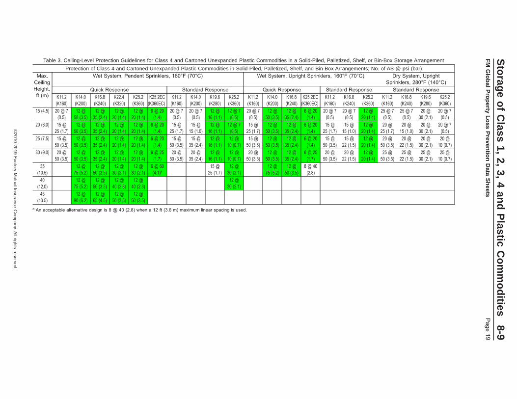
Table 3. Ceiling-Level Protection Guidelines for Class 4 and Cartoned Unexpanded Plastic Commodities in a Solid-Piled, Palletized, Shelf, or Bin-Box Storage Arrangement
Protection of Class 4 and Cartoned Unexpanded Plastic Commodities in Solid-Piled, Palletized, Shelf, and Bin-Box Arrangements; No. of AS @ psi (bar)Max.
CeilingHeight,ft (m)
Wet System, Pendent Sprinklers, 160°F (70°C) Wet System, Upright Sprinklers, 160°F (70°C) Dry System, UprightSprinklers, 280°F (140°C)
Quick Response Standard Response Quick Response Standard Response Standard ResponseK11.2(K160)
K14.0(K200)
K16.8(K240)
K22.4(K320)
K25.2(K360)
K25.2EC(K360EC)
K11.2(K160)
K14.0(K200)
K19.6(K280)
K25.2(K360)
K11.2(K160)
K14.0(K200)
K16.8(K240)
K25.2EC(K360EC)
K11.2(K160)
K16.8(K240)
K25.2(K360)
K11.2(K160)
K16.8(K240)
K19.6(K280)
K25.2(K360)
15 (4.5) 20 @ 7(0.5)
12 @50 (3.5)
12 @35 (2.4)
12 @20 (1.4)
12 @20 (1.4)
6 @ 20(1.4)
20 @ 7(0.5)
20 @ 7(0.5)
12 @16 (1.1)
12 @ 7(0.5)
20 @ 7(0.5)
12 @50 (3.5)
12 @35 (2.4)
6 @ 20(1.4)
20 @ 7(0.5)
20 @ 7(0.5)
12 @20 (1.4)
25 @ 7(0.5)
25 @ 7(0.5)
20 @30 (2.1)
20 @ 7(0.5)
20 (6.0) 15 @25 (1.7)
12 @50 (3.5)
12 @35 (2.4)
12 @20 (1.4)
12 @20 (1.4)
6 @ 20(1.4)
15 @25 (1.7)
15 @15 (1.0)
12 @16 (1.1)
12 @ 7(0.5)
15 @25 (1.7)
12 @50 (3.5)
12 @35 (2.4)
6 @ 20(1.4)
15 @25 (1.7)
15 @15 (1.0)
12 @20 (1.4)
20 @25 (1.7)
20 @15 (1.0)
20 @30 (2.1)
20 @ 7(0.5)
25 (7.5) 15 @50 (3.5)
12 @50 (3.5)
12 @35 (2.4)
12 @20 (1.4)
12 @20 (1.4)
6 @ 20(1.4)
15 @50 (3.5)
15 @35 (2.4)
12 @16 (1.1)
12 @10 (0.7)
15 @50 (3.5)
12 @50 (3.5)
12 @35 (2.4)
6 @ 20(1.4)
15 @50 (3.5)
15 @22 (1.5)
12 @20 (1.4)
20 @50 (3.5)
20 @22 (1.5)
20 @30 (2.1)
20 @10 (0.7)
30 (9.0) 20 @50 (3.5)
12 @50 (3.5)
12 @35 (2.4)
12 @20 (1.4)
12 @20 (1.4)
6 @ 25(1.7)
20 @50 (3.5)
20 @35 (2.4)
12 @16 (1.1)
12 @10 (0.7)
20 @50 (3.5)
12 @50 (3.5)
12 @35 (2.4)
6 @ 25(1.7)
20 @50 (3.5)
20 @22 (1.5)
12 @20 (1.4)
25 @50 (3.5)
25 @22 (1.5)
25 @30 (2.1)
25 @10 (0.7)
35(10.5)
12 @75 (5.2)
12 @50 (3.5)
12 @30 (2.1)
12 @30 (2.1)
6 @ 60(4.1)a
15 @25 (1.7)
12 @30 (2.1)
12 @75 (5.2)
12 @50 (3.5)
8 @ 40(2.8)
40(12.0)
12 @75 (5.2)
12 @50 (3.5)
12 @40 (2.8)
12 @40 (2.8)
12 @30 (2.1)
45(13.5)
12 @90 (6.2)
12 @65 (4.5)
12 @50 (3.5)
12 @50 (3.5)
a An acceptable alternative design is 8 @ 40 (2.8) when a 12 ft (3.6 m) maximum linear spacing is used.
Sto
rage
of
Class
1,2,
3,4
and
Plastic
Co
mm
od
ities8-9
FM
Glo
bal
Pro
perty
Lo
ssP
reventio
nD
ataS
heets
Page
19
©2010-2019
FactoryM
utualInsuranceC
ompany.A
llrightsreserved.

Table 4. Ceiling-Level Protection Guidelines for Cartoned Expanded Plastic Commodities in a Solid-Piled, Palletized, Shelf, or Bin-Box Storage Arrangement
Protection of Cartoned Expanded Plastic Commodities in Solid-Piled, Palletized, Shelf, and Bin-Box Arrangements; No. of AS @ psi (bar)Max.
CeilingHeight,ft (m)
Wet System, Pendent Sprinklers, 160°F (70°C) Wet System, Upright Sprinklers, 160°F (70°C) Dry System, UprightSprinklers, 280°F (140°C)
Quick Response Standard Response Quick Response Standard Response Standard ResponseK11.2(K160)
K14.0(K200)
K16.8(K240)
K22.4(K320)
K25.2(K360)
K25.2EC(K360EC)
K11.2(K160)
K14.0(K200)
K19.6(K280)
K25.2(K360)
K11.2(K160)
K14.0(K200)
K16.8(K240)
K25.2EC(K360EC)
K11.2(K160)
K16.8(K240)
K25.2(K360)
K11.2(K160)
K16.8(K240)
K19.6(K280)
K25.2(K360)
10 (3.0) 20 @ 7(0.5)
12 @50 (3.5)
12 @35 (2.4)
12 @20 (1.4)
12 @ 20(1.4)
6 @ 20(1.4)
20 @ 7(0.5)
20 @ 7(0.5)
15 @16 (1.1)
15 @ 7(0.5)
20 @ 7(0.5)
12 @50 (3.5)
12 @35 (2.4)
6 @ 20(1.4)
20 @ 7(0.5)
20 @ 7(0.5)
15 @ 7(0.5)
25 @ 7(0.5)
25 @ 7(0.5)
20 @30 (2.1)
20 @ 7(0.5)
15 (4.5) 20 @ 7(0.5)
12 @50 (3.5)
12 @35 (2.4)
12 @20 (1.4)
12 @ 20(1.4)
6 @ 20(1.4)
20 @ 7(0.5)
20 @ 7(0.5)
15 @16 (1.1)
15 @ 7(0.5)
20 @ 7(0.5)
12 @50 (3.5)
12 @35 (2.4)
6 @ 20(1.4)
20 @ 7(0.5)
20 @ 7(0.5)
15 @ 7(0.5)
25 @ 7(0.5)
25 @ 7(0.5)
20 @30 (2.1)
20 @ 7(0.5)
20 (6.0) 15 @25 (1.7)
12 @50 (3.5)
12 @35 (2.4)
12 @20 (1.4)
12 @ 20(1.4)
6 @ 20(1.4)
15 @25 (1.7)
15 @15 (1.0)
15 @16 (1.1)
15 @ 7(0.5)
15 @25 (1.7)
12 @50 (3.5)
12 @35 (2.4)
6 @ 20(1.4)
15 @25 (1.7)
15 @15 (1.0)
15 @ 7(0.5)
20 @25 (1.7)
20 @15 (1.0)
20 @30 (2.1)
20 @ 7(0.5)
25 (7.5) 15 @50 (3.5)
12 @50 (3.5)
12 @35 (2.4)
12 @20 (1.4)
12 @ 20(1.4)
6 @ 20(1.4)
15 @50 (3.5)
15 @35 (2.4)
15 @20 (1.4)
15 @10 (0.7)
15 @50 (3.5)
12 @50 (3.5)
12 @35 (2.4)
6 @ 20(1.4)
15 @50 (3.5)
15 @22 (1.5)
15 @10 (0.7)
20 @50 (3.5)
20 @22 (1.5)
20 @30 (2.1)
20 @10 (0.7)
30 (9.0) 20 @50 (3.5)
12 @50 (3.5)
12 @35 (2.4)
12 @20 (1.4)
12 @ 20(1.4)
10 @40 (2.8)
20 @50 (3.5)
20 @35 (2.4)
20 @20 (1.4)
20 @10 (0.7)
20 @50 (3.5)
12 @50 (3.5)
12 @35 (2.4)
10 @40 (2.8)
20 @50 (3.5)
20 @22 (1.5)
20 @10 (0.7)
25 @50 (3.5)
25 @22 (1.5)
25 @30 (2.1)
25 @10 (0.7)
35(10.5)
12 @ 60(4.1)
40(12.0)
12 @ 60(4.1)
8-9S
torag
eo
fC
lass1,
2,3,
4an
dP
lasticC
om
mo
dities
Page
20F
MG
lob
alP
rop
ertyL
oss
Preven
tion
Data
Sh
eets
©2010-2019
FactoryM
utualInsuranceC
ompany.A
llrightsreserved.
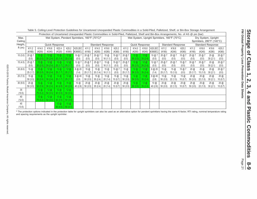
Table 5. Ceiling-Level Protection Guidelines for Uncartoned Unexpanded Plastic Commodities in a Solid-Piled, Palletized, Shelf, or Bin-Box Storage Arrangement
Protection of Uncartoned Unexpanded Plastic Commodities in Solid-Piled, Palletized, Shelf and Bin-Box Arrangements; No. of AS @ psi (bar)Max.
CeilingHeight,ft (m)
Wet System, Pendent Sprinklers, 160°F (70°C)a Wet System, Upright Sprinklers, 160°F (70°C) Dry System, UprightSprinklers, 280°F (140°C)
Quick Response Standard Response Quick Response Standard Response Standard ResponseK11.2(K160)
K14.0(K200)
K16.8(K240)
K22.4(K320)
K25.2(K360)
K25.2EC(K360EC)
K11.2(K160)
K14.0(K200)
K19.6(K280)
K25.2(K360)
K11.2(K160)
K14.0(K200)
K16.8(K240)
K25.2EC(K360EC)
K11.2(K160)
K16.8(K240)
K25.2(K360)
K11.2(K160)
K16.8(K240)
K19.6(K280)
K25.2(K360)
10 (3.0) 20 @ 7(0.5)
12 @50 (3.5)
12 @35 (2.4)
12 @20 (1.4)
12 @20 (1.4)
10 @ 7(0.5)
20 @ 7(0.5)
20 @ 7(0.5)
15 @16 (1.1)
15 @ 7(0.5)
20 @ 7(0.5)
12 @50 (3.5)
12 @35 (2.4)
10 @ 7(0.5)
20 @ 7(0.5)
20 @ 7(0.5)
15 @ 7(0.5)
25 @ 7(0.5)
25 @ 7(0.5)
20 @30 (2.1)
20 @ 7(0.5)
15 (4.5) 25 @ 7(0.5)
12 @50 (3.5)
12 @35 (2.4)
12 @25 (1.7)
12 @25 (1.7)
12 @ 7(0.5)
25 @ 7(0.5)
25 @ 7(0.5)
15 @16 (1.1)
15 @ 7(0.5)
25 @ 7(0.5)
12 @50 (3.5)
12 @35 (2.4)
12 @ 7(0.5)
25 @ 7(0.5)
25 @ 7(0.5)
15 @ 7(0.5)
35 @ 7(0.5)
35 @ 7(0.5)
20 @30 (2.1)
20 @ 7(0.5)
20 (6.0) 15 @25 (1.7)
12 @50 (3.5)
12 @35 (2.4)
12 @25 (1.7)
12 @25 (1.7)
8 @ 20(1.4)
15 @25 (1.7)
15 @20 (1.4)
15 @16 (1.1)
15 @ 7(0.5)
15 @25 (1.7)
12 @50 (3.5)
12 @35 (2.4)
8 @ 20(1.4)
15 @25 (1.7)
15 @15 (1.0)
15 @ 7(0.5)
20 @25 (1.7)
20 @15 (1.0)
20 @30 (2.1)
20 @ 7(0.5)
25 (7.5) 15 @50 (3.5)
12 @50 (3.5)
12 @35 (2.4)
12 @25 (1.7)
12 @25 (1.7)
8 @ 40(2.8)
15 @50 (3.5)
15 @35 (2.4)
15 @20 (1.4)
15 @10 (0.7)
15 @50 (3.5)
12 @50 (3.5)
12 @35 (2.4)
8 @ 40(2.8)
15 @50 (3.5)
15 @22 (1.5)
15 @10 (0.7)
20 @50 (3.5)
20 @22 (1.5)
20 @30 (2.1)
20 @10 (0.7)
30 (9.0) 20 @50 (3.5)
12 @50 (3.5)
12 @35 (2.4)
10 @40 (2.8)
10 @40 (2.8)
10 @40 (2.8)
20 @50 (3.5)
20 @35 (2.4)
20 @20 (1.4)
20 @10 (0.7)
20 @50 (3.5)
12 @50 (3.5)
12 @35 (2.4)
10 @40 (2.8)
20 @50 (3.5)
20 @22 (1.5)
20 @10 (0.7)
25 @50 (3.5)
25 @22 (1.5)
25 @30 (2.1)
25 @10 (0.7)
35(10.5)
12 @75 (5.2)
12 @50 (3.5)
12 @50 (3.5)
12 @50 (3.5)
40(12.0)
12 @75 (5.2)
12 @50 (3.5)
12 @50 (3.5)
12 @50 (3.5)
45(13.5)
12 @65 (4.5)
12 @60 (4.1)
a The protection options indicated in the protection table for upright sprinklers can also be used as an alternative option for pendent sprinklers having the same K-factor, RTI rating, nominal temperature ratingand spacing requirements as the upright sprinkler.
Sto
rage
of
Class
1,2,
3,4
and
Plastic
Co
mm
od
ities8-9
FM
Glo
bal
Pro
perty
Lo
ssP
reventio
nD
ataS
heets
Page
21
©2010-2019
FactoryM
utualInsuranceC
ompany.A
llrightsreserved.
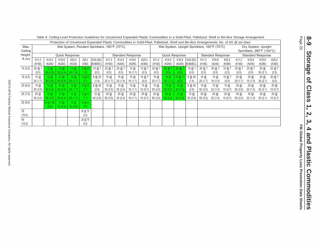
Table 6. Ceiling-Level Protection Guidelines for Uncartoned Expanded Plastic Commodities in a Solid-Piled, Palletized, Shelf or Bin-Box Storage Arrangement
Protection of Uncartoned Expanded Plastic Commodities in Solid-Piled, Palletized, Shelf and Bin-Box Arrangements; No. of AS @ psi (bar)Max.
CeilingHeight,ft (m)
Wet System, Pendent Sprinklers, 160°F (70°C) Wet System, Upright Sprinklers, 160°F (70°C) Dry System, UprightSprinklers, 280°F (140°C)
Quick Response Standard Response Quick Response Standard Response Standard ResponseK11.2(K160)
K14.0(K200)
K16.8(K240)
K22.4(K320)
K25.2(K360)
K25.2EC(K360EC)
K11.2(K160)
K14.0(K200)
K19.6(K280)
K25.2(K360)
K11.2(K160)
K14.0(K200)
K16.8(K240)
K25.2EC(K360EC)
K11.2(K160)
K16.8(K240)
K25.2(K360)
K11.2(K160)
K16.8(K240)
K19.6(K280)
K25.2(K360)
10 (3.0) 20 @ 7(0.5)
12 @50 (3.5)
12 @35 (2.4)
12 @20 (1.4)
12 @ 20(1.4)
10 @ 7(0.5)
20 @ 7(0.5)
20 @ 7(0.5)
15 @16 (1.1)
15 @ 7(0.5)
20 @ 7(0.5)
20 @ 7(0.5)
20 @ 7(0.5)
10 @ 7(0.5)
20 @ 7(0.5)
20 @ 7(0.5)
15 @ 7(0.5)
25 @ 7(0.5)
25 @ 7(0.5)
20 @30 (2.1)
20 @ 7(0.5)
15 (4.5) 15 @25 (1.7)
12 @50 (3.5)
12 @35 (2.4)
12 @25 (1.7)
12 @ 25(1.7)
8 @ 20(1.4)
15 @25 (1.7)
15 @20 (1.4)
15 @16 (1.1)
15 @ 7(0.5)
15 @25 (1.7)
15 @16 (1.1)
15 @ 11(0.8)
8 @ 20(1.4)
15 @25 (1.7)
15 @15 (1.0)
15 @ 7(0.5)
20 @25 (1.7)
20 @15 (1.0)
20 @30 (2.1)
20 @ 7(0.5)
20 (6.0) 15 @50 (3.5)
12 @50 (3.5)
12 @35 (2.4)
12 @25 (1.7)
12 @ 25(1.7)
8 @ 40(2.8)
15 @50 (3.5)
15 @35 (2.4)
15 @16 (1.1)
15 @10 (0.7)
15 @50 (3.5)
15 @32 (2.2)
15 @22 (1.5)
8 @ 40(2.8)
15 @50 (3.5)
15 @22 (1.5)
15 @10 (0.7)
20 @50 (3.5)
20 @22 (1.5)
20 @30 (2.1)
20 @10 (0.7)
25 (7.5) 25 @50 (3.5)
12 @50 (3.5)
12 @35 (2.4)
12 @25 (1.7)
12 @ 25(1.7)
12 @40 (2.8)
25 @50 (3.5)
25 @35 (2.4)
25 @16 (1.1)
25 @10 (0.7)
25 @50 (3.5)
25 @32 (2.2)
25 @22 (1.5)
12 @40 (2.8)
25 @50 (3.5)
25 @22 (1.5)
25 @10 (0.7)
35 @50 (3.5)
35 @22 (1.5)
35 @30 (2.1)
35 @10 (0.7)
30 (9.0) 12 @ 100(6.9)
12 @70 (4.8)
10 @40 (2.8)
10 @ 40(2.8)
35(10.5)
20 @ 75(5.2)
40(12.0)
20 @ 75(5.2)
8-9S
torag
eo
fC
lass1,
2,3,
4an
dP
lasticC
om
mo
dities
Page
22F
MG
lob
alP
rop
ertyL
oss
Preven
tion
Data
Sh
eets
©2010-2019
FactoryM
utualInsuranceC
ompany.A
llrightsreserved.
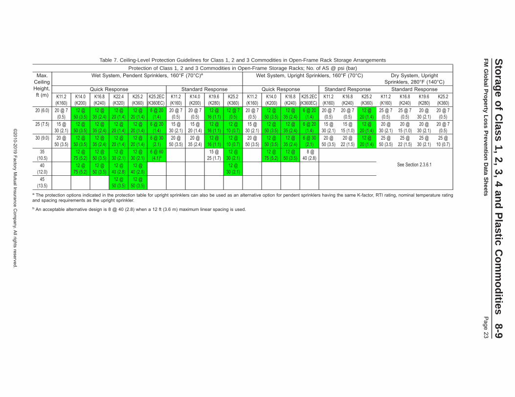
Table 7. Ceiling-Level Protection Guidelines for Class 1, 2 and 3 Commodities in Open-Frame Rack Storage Arrangements
Protection of Class 1, 2 and 3 Commodities in Open-Frame Storage Racks; No. of AS @ psi (bar)Max.
CeilingHeight,ft (m)
Wet System, Pendent Sprinklers, 160°F (70°C)a Wet System, Upright Sprinklers, 160°F (70°C) Dry System, UprightSprinklers, 280°F (140°C)
Quick Response Standard Response Quick Response Standard Response Standard ResponseK11.2(K160)
K14.0(K200)
K16.8(K240)
K22.4(K320)
K25.2(K360)
K25.2EC(K360EC)
K11.2(K160)
K14.0(K200)
K19.6(K280)
K25.2(K360)
K11.2(K160)
K14.0(K200)
K16.8(K240)
K25.2EC(K360EC)
K11.2(K160)
K16.8(K240)
K25.2(K360)
K11.2(K160)
K16.8(K240)
K19.6(K280)
K25.2(K360)
20 (6.0) 20 @ 7(0.5)
12 @50 (3.5)
12 @35 (2.4)
12 @20 (1.4)
12 @20 (1.4)
6 @ 20(1.4)
20 @ 7(0.5)
20 @ 7(0.5)
12 @16 (1.1)
12 @ 7(0.5)
20 @ 7(0.5)
12 @50 (3.5)
12 @35 (2.4)
6 @ 20(1.4)
20 @ 7(0.5)
20 @ 7(0.5)
12 @20 (1.4)
25 @ 7(0.5)
25 @ 7(0.5)
20 @30 (2.1)
20 @ 7(0.5)
25 (7.5) 15 @30 (2.1)
12 @50 (3.5)
12 @35 (2.4)
12 @20 (1.4)
12 @20 (1.4)
6 @ 20(1.4)
15 @30 (2.1)
15 @20 (1.4)
12 @16 (1.1)
12 @10 (0.7)
15 @30 (2.1)
12 @50 (3.5)
12 @35 (2.4)
6 @ 20(1.4)
15 @30 (2.1)
15 @15 (1.0)
12 @20 (1.4)
20 @30 (2.1)
20 @15 (1.0)
20 @30 (2.1)
20 @ 7(0.5)
30 (9.0) 20 @50 (3.5)
12 @50 (3.5)
12 @35 (2.4)
12 @20 (1.4)
12 @20 (1.4)
6 @ 30(2.1)
20 @50 (3.5)
20 @35 (2.4)
12 @16 (1.1)
12 @10 (0.7)
20 @50 (3.5)
12 @50 (3.5)
12 @35 (2.4)
6 @ 30(2.1)
20 @50 (3.5)
20 @22 (1.5)
12 @20 (1.4)
25 @50 (3.5)
25 @22 (1.5)
25 @30 (2.1)
25 @10 (0.7)
35(10.5)
12 @75 (5.2)
12 @50 (3.5)
12 @30 (2.1)
12 @30 (2.1)
6 @ 60(4.1)b
15 @25 (1.7)
12 @30 (2.1)
12 @75 (5.2)
12 @50 (3.5)
8 @40 (2.8)
See Section 2.3.6.140(12.0)
12 @75 (5.2)
12 @50 (3.5)
12 @40 (2.8)
12 @40 (2.8)
12 @30 (2.1)
45(13.5)
12 @50 (3.5)
12 @50 (3.5)
a The protection options indicated in the protection table for upright sprinklers can also be used as an alternative option for pendent sprinklers having the same K-factor, RTI rating, nominal temperature ratingand spacing requirements as the upright sprinkler.b An acceptable alternative design is 8 @ 40 (2.8) when a 12 ft (3.6 m) maximum linear spacing is used.
Sto
rage
of
Class
1,2,
3,4
and
Plastic
Co
mm
od
ities8-9
FM
Glo
bal
Pro
perty
Lo
ssP
reventio
nD
ataS
heets
Page
23
©2010-2019
FactoryM
utualInsuranceC
ompany.A
llrightsreserved.
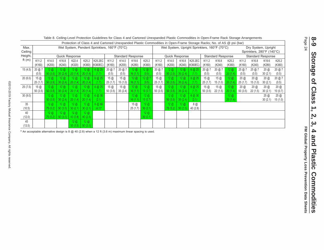
Table 8. Ceiling-Level Protection Guidelines for Class 4 and Cartoned Unexpanded Plastic Commodities in Open-Frame Rack Storage Arrangements
Protection of Class 4 and Cartoned Unexpanded Plastic Commodities in Open-Frame Storage Racks; No. of AS @ psi (bar)Max.
CeilingHeight,ft (m)
Wet System, Pendent Sprinklers, 160°F (70°C) Wet System, Upright Sprinklers, 160°F (70°C) Dry System, UprightSprinklers, 280°F (140°C)
Quick Response Standard Response Quick Response Standard Response Standard ResponseK11.2(K160)
K14.0(K200)
K16.8(K240)
K22.4(K320)
K25.2(K360)
K25.2EC(K360EC)
K11.2(K160)
K14.0(K200)
K19.6(K280)
K25.2(K360)
K11.2(K160)
K14.0(K200)
K16.8(K240)
K25.2EC(K360EC)
K11.2(K160)
K16.8(K240)
K25.2(K360)
K11.2(K160)
K16.8(K240)
K19.6(K280)
K25.2(K360)
15 (4.5) 20 @ 7(0.5)
12 @50 (3.5)
12 @35 (2.4)
12 @20 (1.4)
12 @20 (1.4)
6 @ 25(1.7)
20 @ 7(0.5)
20 @ 7(0.5)
12 @16 (1.1)
12 @ 7(0.5)
20 @ 7(0.5)
12 @50 (3.5)
12 @35 (2.4)
6 @ 25(1.7)
20 @ 7(0.5)
20 @ 7(0.5)
12 @20 (1.4)
25 @ 7(0.5)
25 @ 7(0.5)
20 @30 (2.1)
20 @ 7(0.5)
20 (6.0) 15 @25 (1.7)
12 @50 (3.5)
12 @35 (2.4)
12 @20 (1.4)
12 @20 (1.4)
6 @ 25(1.7)
15 @25 (1.7)
15 @15 (1.0)
12 @16 (1.1)
12 @ 7(0.5)
15 @25 (1.7)
12 @50 (3.5)
12 @35 (2.4)
6 @ 25(1.7)
15 @25 (1.7)
15 @15 (1.0)
12 @20 (1.4)
20 @25 (1.7)
20 @15 (1.0)
20 @30 (2.1)
20 @ 7(0.5)
25 (7.5) 15 @50 (3.5)
12 @50 (3.5)
12 @35 (2.4)
12 @20 (1.4)
12 @20 (1.4)
6 @ 25(1.7)
15 @50 (3.5)
15 @35 (2.4)
12 @16 (1.1)
12 @10 (0.7)
15 @50 (3.5)
12 @50 (3.5)
12 @35 (2.4)
6 @ 25(1.7)
15 @50 (3.5)
15 @22 (1.5)
12 @20 (1.4)
20 @50 (3.5)
20 @22 (1.5)
20 @30 (2.1)
20 @10 (0.7)
30 (9.0) 12 @50 (3.5)
12 @35 (2.4)
12 @20 (1.4)
12 @20 (1.4)
6 @ 30(2.1)
12 @16 (1.1)
12 @10 (0.7)
12 @50 (3.5)
12 @35 (2.4)
6 @ 30(2.1)
12 @20 (1.4)
25 @30 (2.1)
25 @15 (1.0)
35(10.5)
12 @75 (5.2)
12 @50 (3.5)
12 @30 (2.1)
12 @30 (2.1)
6 @ 60(4.1)a
15 @25 (1.7)
12 @30 (2.1)
12 @75 (5.2)
12 @50 (3.5)
8 @40 (2.8)
40(12.0)
12 @75 (5.2)
12 @50 (3.5)
12 @40 (2.8)
12 @40 (2.8)
12 @30 (2.1)
45(13.5)
12 @50 (3.5)
12 @50 (3.5)
a An acceptable alternative design is 8 @ 40 (2.8) when a 12 ft (3.6 m) maximum linear spacing is used.
8-9S
torag
eo
fC
lass1,
2,3,
4an
dP
lasticC
om
mo
dities
Page
24F
MG
lob
alP
rop
ertyL
oss
Preven
tion
Data
Sh
eets
©2010-2019
FactoryM
utualInsuranceC
ompany.A
llrightsreserved.
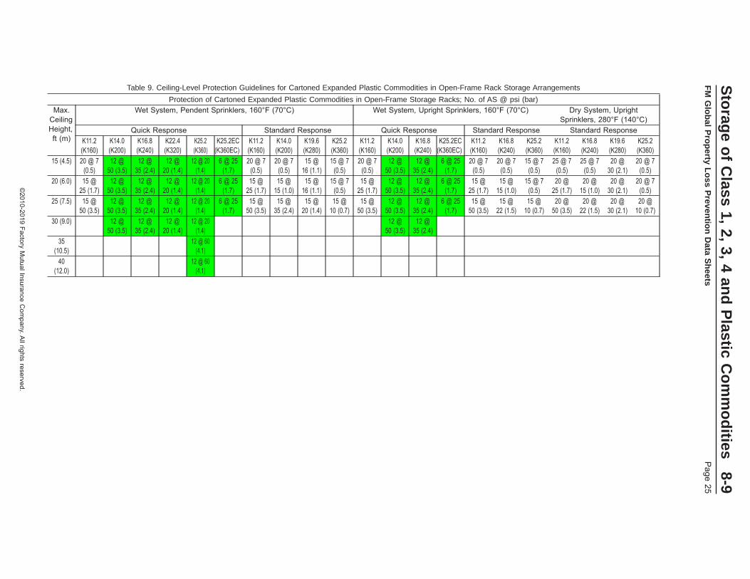
Table 9. Ceiling-Level Protection Guidelines for Cartoned Expanded Plastic Commodities in Open-Frame Rack Storage Arrangements
Protection of Cartoned Expanded Plastic Commodities in Open-Frame Storage Racks; No. of AS @ psi (bar)Max.
CeilingHeight,ft (m)
Wet System, Pendent Sprinklers, 160°F (70°C) Wet System, Upright Sprinklers, 160°F (70°C) Dry System, UprightSprinklers, 280°F (140°C)
Quick Response Standard Response Quick Response Standard Response Standard ResponseK11.2(K160)
K14.0(K200)
K16.8(K240)
K22.4(K320)
K25.2(K360)
K25.2EC(K360EC)
K11.2(K160)
K14.0(K200)
K19.6(K280)
K25.2(K360)
K11.2(K160)
K14.0(K200)
K16.8(K240)
K25.2EC(K360EC)
K11.2(K160)
K16.8(K240)
K25.2(K360)
K11.2(K160)
K16.8(K240)
K19.6(K280)
K25.2(K360)
15 (4.5) 20 @ 7(0.5)
12 @50 (3.5)
12 @35 (2.4)
12 @20 (1.4)
12 @ 20(1.4)
6 @ 25(1.7)
20 @ 7(0.5)
20 @ 7(0.5)
15 @16 (1.1)
15 @ 7(0.5)
20 @ 7(0.5)
12 @50 (3.5)
12 @35 (2.4)
6 @ 25(1.7)
20 @ 7(0.5)
20 @ 7(0.5)
15 @ 7(0.5)
25 @ 7(0.5)
25 @ 7(0.5)
20 @30 (2.1)
20 @ 7(0.5)
20 (6.0) 15 @25 (1.7)
12 @50 (3.5)
12 @35 (2.4)
12 @20 (1.4)
12 @ 20(1.4)
6 @ 25(1.7)
15 @25 (1.7)
15 @15 (1.0)
15 @16 (1.1)
15 @ 7(0.5)
15 @25 (1.7)
12 @50 (3.5)
12 @35 (2.4)
6 @ 25(1.7)
15 @25 (1.7)
15 @15 (1.0)
15 @ 7(0.5)
20 @25 (1.7)
20 @15 (1.0)
20 @30 (2.1)
20 @ 7(0.5)
25 (7.5) 15 @50 (3.5)
12 @50 (3.5)
12 @35 (2.4)
12 @20 (1.4)
12 @ 20(1.4)
6 @ 25(1.7)
15 @50 (3.5)
15 @35 (2.4)
15 @20 (1.4)
15 @10 (0.7)
15 @50 (3.5)
12 @50 (3.5)
12 @35 (2.4)
6 @ 25(1.7)
15 @50 (3.5)
15 @22 (1.5)
15 @10 (0.7)
20 @50 (3.5)
20 @22 (1.5)
20 @30 (2.1)
20 @10 (0.7)
30 (9.0) 12 @50 (3.5)
12 @35 (2.4)
12 @20 (1.4)
12 @ 20(1.4)
12 @50 (3.5)
12 @35 (2.4)
35(10.5)
12 @ 60(4.1)
40(12.0)
12 @ 60(4.1)
Sto
rage
of
Class
1,2,
3,4
and
Plastic
Co
mm
od
ities8-9
FM
Glo
bal
Pro
perty
Lo
ssP
reventio
nD
ataS
heets
Page
25
©2010-2019
FactoryM
utualInsuranceC
ompany.A
llrightsreserved.

Table 10. Ceiling-Level Protection Guidelines for Uncartoned Unexpanded Plastic Commodities in Open-Frame Rack Storage Arrangements
Protection of Uncartoned Unexpanded Plastic Commodities in Open-Frame Storage Racks; No. of AS @ psi (bar)Max.
CeilingHeight,ft (m)
Wet System, Pendent Sprinklers, 160°F (70°C)a Wet System, Upright Sprinklers, 160°F (70°C) Dry System, UprightSprinklers, 280°F (140°C)
Quick Response Standard Response Quick Response Standard Response Standard ResponseK11.2(K160)
K14.0(K200)
K16.8(K240)
K22.4(K320)
K25.2(K360)
K25.2EC(K360EC)
K11.2(K160)
K14.0(K200)
K19.6(K280)
K25.2(K360)
K11.2(K160)
K14.0(K200)
K16.8(K240)
K25.2EC(K360EC)
K11.2(K160)
K16.8(K240)
K25.2(K360)
K11.2(K160)
K16.8(K240)
K19.6(K280)
K25.2(K360)
5 (1.5) 20 @ 7(0.5)
12 @50 (3.5)
12 @35 (2.4)
12 @20 (1.4)
12 @20 (1.4)
10 @ 7(0.5)
20 @ 7(0.5)
20 @ 7(0.5)
20 @16 (1.1)
20 @ 7(0.5)
20 @ 7(0.5)
20 @ 7(0.5)
20 @ 7(0.5)
10 @ 7(0.5)
20 @ 7(0.5)
20 @ 7(0.5)
20 @ 7(0.5)
25 @ 7(0.5)
25 @ 7(0.5)
25 @30 (2.1)
25 @ 7(0.5)
8 (2.4) 20 @16 (1.1)
12 @50 (3.5)
12 @35 (2.4)
12 @20 (1.4)
12 @20 (1.4)
10 @12 (0.8)
20 @16 (1.1)
20 @10 (0.7)
20 @16 (1.1)
20 @ 7(0.5)
20 @16 (1.1)
20 @10 (0.7)
20 @ 7(0.5)
10 @12 (0.8)
20 @16 (1.1)
20 @ 7(0.5)
20 @ 7(0.5)
25 @16 (1.1)
25 @ 7(0.5)
25 @30 (2.1)
25 @ 7(0.5)
10 (3.0) 20 @30 (2.1)
12 @50 (3.5)
12 @35 (2.4)
12 @20 (1.4)
12 @20 (1.4)
10 @22 (1.5)
20 @30 (2.1)
20 @20 (1.4)
20 @16 (1.1)
20 @ 7(0.5)
20 @30 (2.1)
20 @20 (1.4)
20 @13 (0.9)
10 @22 (1.5)
20 @30 (2.1)
20 @13 (0.9)
20 @ 7(0.5)
25 @30 (2.1)
25 @13 (0.9)
25 @30 (2.1)
25 @ 7(0.5)
12 (3.6) 20 @50 (3.5)
12 @50 (3.5)
12 @35 (2.4)
12 @25 (1.7)
12 @25 (1.7)
10 @40 (2.8)
20 @50 (3.5)
20 @35 (2.4)
20 @16 (1.1)
20 @10 (0.7)
20 @50 (3.5)
20 @35 (2.4)
20 @25 (1.7)
10 @40 (2.8)
20 @50 (3.5)
20 @22 (1.5)
20 @10 (0.7)
25 @50 (3.5)
25 @22 (1.5)
25 @30 (2.1)
25 @10 (0.7)
15 (4.5) 25 @50 (3.5)
12 @50 (3.5)
12 @35 (2.4)
12 @25 (1.7)
12 @25 (1.7)
12 @40 (2.8)
25 @50 (3.5)
25 @35 (2.4)
25 @16 (1.1)
25 @10 (0.7)
25 @50 (3.5)
25 @35 (2.4)
25 @25 (1.7)
12 @40 (2.8)
25 @50 (3.5)
25 @22 (1.5)
25 @10 (0.7)
30 @50 (3.5)
30 @22 (1.5)
30 @30 (2.1)
30 @10 (0.7)
20 (6.0) 12 @50 (3.5)
12 @35 (2.4)
12 @25 (1.7)
12 @25 (1.7)
6 @ 90(6.2)
12 @75 (5.2)
12 @40 (2.8)
12 @25 (1.7)
25 (7.5) 12 @50 (3.5)
12 @35 (2.4)
12 @30 (2.1)
12 @30 (2.1)
30 (9.0) 12 @75 (5.2)
12 @50 (3.5)
10 @40 (2.8)
10 @40 (2.8)
35(10.5)
12 @60 (4.1)
40(12.0)
12 @60 (4.1)
a The protection options indicated in the protection table for upright sprinklers can also be used as an alternative option for pendent sprinklers having the same K-factor, RTI rating, nominal temperature ratingand spacing requirements as the upright sprinkler.
8-9S
torag
eo
fC
lass1,
2,3,
4an
dP
lasticC
om
mo
dities
Page
26F
MG
lob
alP
rop
ertyL
oss
Preven
tion
Data
Sh
eets
©2010-2019
FactoryM
utualInsuranceC
ompany.A
llrightsreserved.
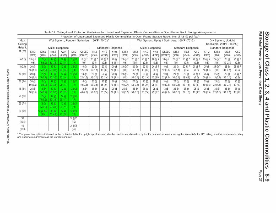
Table 11. Ceiling-Level Protection Guidelines for Uncartoned Expanded Plastic Commodities in Open-Frame Rack Storage Arrangements
Protection of Uncartoned Expanded Plastic Commodities in Open-Frame Storage Racks; No. of AS @ psi (bar)Max.
CeilingHeight,ft (m)
Wet System, Pendent Sprinklers, 160°F (70°C)a Wet System, Upright Sprinklers, 160°F (70°C) Dry System, UprightSprinklers, 280°F (140°C)
Quick Response Standard Response Quick Response Standard Response Standard ResponseK11.2(K160)
K14.0(K200)
K16.8(K240)
K22.4(K320)
K25.2(K360)
K25.2EC(K360EC)
K11.2(K160)
K14.0(K200)
K19.6(K280)
K25.2(K360)
K11.2(K160)
K14.0(K200)
K16.8(K240)
K25.2EC(K360EC)
K11.2(K160)
K16.8(K240)
K25.2(K360)
K11.2(K160)
K16.8(K240)
K19.6(K280)
K25.2(K360)
5 (1.5) 20 @ 7(0.5)
12 @75 (5.2)
12 @50 (3.5)
12 @20 (1.4)
12 @ 20(1.4)
10 @ 7(0.5)
20 @ 7(0.5)
20 @ 7(0.5)
20 @16 (1.1)
20 @ 7(0.5)
20 @ 7(0.5)
20 @ 7(0.5)
20 @ 7(0.5)
10 @ 7(0.5)
20 @ 7(0.5)
20 @ 7(0.5)
20 @ 7(0.5)
25 @ 7(0.5)
25 @ 7(0.5)
25 @30 (2.1)
25 @ 7(0.5)
8 (2.4) 20 @16 (1.1)
12 @75 (5.2)
12 @50 (3.5)
12 @20 (1.4)
12 @ 20(1.4)
10 @12 (0.8)
20 @16 (1.1)
20 @10 (0.7)
20 @16 (1.1)
20 @ 7(0.5)
20 @16 (1.1)
20 @10 (0.7)
20 @ 7(0.5)
10 @12 (0.8)
20 @16 (1.1)
20 @ 7(0.5)
20 @ 7(0.5)
25 @16 (1.1)
25 @ 7(0.5)
25 @30 (2.1)
25 @ 7(0.5)
10 (3.0) 20 @30 (2.1)
12 @75 (5.2)
12 @50 (3.5)
12 @20 (1.4)
12 @ 20(1.4)
10 @22 (1.5)
20 @30 (2.1)
20 @20 (1.4)
20 @16 (1.1)
20 @ 7(0.5)
20 @30 (2.1)
20 @20 (1.4)
20 @13 (0.9)
10 @22 (1.5)
20 @30 (2.1)
20 @13 (0.9)
20 @ 7(0.5)
25 @30 (2.1)
25 @13 (0.9)
25 @30 (2.1)
25 @ 7(0.5)
12 (3.6) 20 @50 (3.5)
12 @75 (5.2)
12 @50 (3.5)
12 @25 (1.7)
12 @ 25(1.7)
10 @40 (2.8)
20 @50 (3.5)
20 @35 (2.4)
20 @16 (1.1)
20 @10 (0.7)
20 @50 (3.5)
20 @35 (2.4)
20 @25 (1.7)
10 @40 (2.8)
20 @50 (3.5)
20 @22 (1.5)
20 @10 (0.7)
25 @50 (3.5)
25 @22 (1.5)
25 @30 (2.1)
25 @10 (0.7)
15 (4.5) 25 @50 (3.5)
12 @75 (5.2)
12 @50 (3.5)
12 @25 (1.7)
12 @ 25(1.7)
12 @40 (2.8)
25 @50 (3.5)
25 @35 (2.4)
25 @16 (1.1)
25 @10 (0.7)
25 @50 (3.5)
25 @35 (2.4)
25 @25 (1.7)
12 @40 (2.8)
25 @50 (3.5)
25 @22 (1.5)
25 @10 (0.7)
35 @50 (3.5)
35 @22 (1.5)
35 @30 (2.1)
35 @10 (0.7)
20 (6.0) 12 @75 (5.2)
12 @50 (3.5)
12 @25 (1.7)
12 @ 25(1.7)
25 (7.5) 12 @75 (5.2)
12 @50 (3.5)
12 @30 (2.1)
12 @ 30(2.1)
30 (9.0) 12 @ 100(6.9)
12 @70 (4.8)
12 @40 (2.8)
12 @ 40(2.8)
35(10.5)
20 @ 75(5.2)
40(12.0)
20 @ 75(5.2)
a The protection options indicated in the protection table for upright sprinklers can also be used as an alternative option for pendent sprinklers having the same K-factor, RTI rating, nominal temperature ratingand spacing requirements as the upright sprinkler.
Sto
rage
of
Class
1,2,
3,4
and
Plastic
Co
mm
od
ities8-9
FM
Glo
bal
Pro
perty
Lo
ssP
reventio
nD
ataS
heets
Page
27
©2010-2019
FactoryM
utualInsuranceC
ompany.A
llrightsreserved.

2.3.3.7.3 Ceiling Heights in Excess of Those Indicated in Protection Tables for Ceiling-Level StorageSprinklers
When ceiling heights at storage facilities are in excess of those indicated in the applicable protection tablefrom Section 2.3.3.7.2, see the guidelines in Section 2.3.3.7.3.1 for storage arrangements involving racks, orSection 2.3.3.7.3.2 for solid-piled, palletized, shelf, and bin-box storage arrangements.
2.3.3.7.3.1 Ceiling Heights in Excess of Those Indicated in Protection Tables for Ceiling-Level StorageSprinklers Protecting Rack Storage
When ceiling heights at storage facilities are in excess of what is indicated in the applicable protection tablein Section 2.3.3.7.2 for the commodity being protected, a ceiling-only sprinkler system is not an option.
Implement one of the two options listed below when ceiling-only options are not available.
2.3.3.7.3.1.1. Option 1: Installation of a False Ceiling
Install a noncombustible false ceiling directly over and at least 15 ft (4.5 m) beyond the storage area. Designthe false ceiling in accordance with Data Sheet 1-12, Ceilings and Concealed Spaces. Provide sprinklersunder the false ceiling and design them based on the guidelines indicated in the applicable protection tablefor the height above the floor over which the false ceiling has been installed. If, however, in-racks are stillneeded, even in the presence of a false ceiling, design the sprinklers under the false ceiling in accordancewith Table 13 as described in Section 2.3.4.8.2.
2.3.3.7.3.1.2. Option 2: Installation of In-Rack Sprinklers
Follow the guidelines In Section 2.3.4.6 to determine the acceptable horizontal layout of the in-rack sprinklers,and Section 2.3.4.7 for the vertical increments in which the in-rack sprinklers can be installed.
If there is more than 20 ft (6.0 m) of vertical clearance between the top of storage and the ceiling above,supplement the existing in-rack sprinkler arrangement obtained from Sections 2.3.4.6 and 2.3.4.7 by installingin-rack sprinklers at the top tier level of the storage rack. Use an in-rack arrangement in accordance withFigures 11, 13, and 14, depending on the rack type. If a horizontal barrier is provided above this top level ofin-rack sprinklers, Figure 12 can be used as an alternative for double-row racks, and Figure 10 can be usedas an alternative for multiple-row racks. Design the ceiling-level sprinklers in accordance with Table 13(Section 2.3.4.8.2) based on an IRAS(E) in-rack sprinkler arrangement and ceiling clearance of 20 ft (6.0m). Limit the storage on the top tier to a maximum of 5 ft (1.5 m).
2.3.3.7.3.2 Ceiling Heights in Excess of Those Indicated in Protection Tables for Ceiling-Level StorageSprinklers Protecting Solid-Piled, Palletized, Shelf, or Bin-Box Storage Arrangements
When ceiling heights at storage facilities are in excess of what is indicated in the applicable protection tablein Section 2.3.3.7.2 for the commodity being protected, a ceiling-only sprinkler system is not an option.
Implement one of the two options listed below when ceiling-only options are not available.
2.3.3.7.3.2.1 Option 1: Installation of a False Ceiling
Install a noncombustible false ceiling directly over and at least 15 ft (4.5 m) beyond the storage area. Designthe false ceiling in accordance with Data Sheet 1-12, Ceilings and Concealed Spaces. Provide sprinklersunder the false ceiling and design them based on the guidelines indicated in the applicable protection tablefor the height above the floor over which the false ceiling has been installed.
2.3.3.7.3.2.2 Option 2: Installation of In-Rack Sprinklers
If a false ceiling as indicated in Option 1 cannot be installed, the storage arrangement will need to be convertedto a rack storage arrangement protected with in-rack sprinklers. Follow the guidelines in Section 2.3.3.7.3.1.2for the installation of in-rack sprinklers within these storage racks.
2.3.4 In-Rack Sprinklers (IRAS)
2.3.4.1 General
Protection options for rack storage arrangements are based on ceiling-only sprinkler systems, or acombination of ceiling-level and in-rack sprinkler systems. When in-rack sprinklers are needed, they canbe used in combination with any of the ceiling sprinklers listed in Tables 7 through 11.
8-9 Storage of Class 1, 2, 3, 4 and Plastic CommoditiesPage 28 FM Global Property Loss Prevention Data Sheets
©2010-2019 Factory Mutual Insurance Company. All rights reserved.
2.3.4.1.1 When in-rack sprinklers are needed as a supplement to ceiling-level sprinklers, as outlined in Section2.3.4.2, use FM Approved in-rack sprinklers listed in the Approval Guide, an online resource of FM Approvals,under the heading of Storage Sprinklers (In-Racks).
2.3.4.1.2 If in-rack sprinklers are recommended in Section 2.3.4.2 for the rack storage arrangement andcommodity hazard involved, use the following procedure to determine the recommended protection for boththe ceiling and in-rack sprinkler systems:
1. Determine the available horizontal in-rack sprinkler arrangements per Section 2.3.4.6
2. Determine the available vertical increments between in-rack sprinkler levels per Section 2.3.4.7
3. Determine the in-rack sprinkler system design guidelines per Section 2.3.4.8.1
4. Determine the ceiling-level sprinkler system design guidelines when supplemented with in-racksprinklers per Section 2.3.4.8.2
5. Determine the hose demand and duration for the combined ceiling-level and in-rack sprinkler systemper Section 2.3.5.
2.3.4.1.3 See Sections 2.3.6.3 through 2.3.6.7 for additional in-rack sprinkler protection recommendationsthat supplement the recommendations obtained from this section.
2.3.4.2 When In-Rack Sprinklers are Needed
The need for in-rack sprinklers is dependent on several parameters, including commodity hazard, ceilingheight, available water supply, the presence of solid shelves, and the width and location of flue spaces. SeeAppendix A for an explanation of how the width and location of flue spaces affects the classification ofopen-frame racking. The following guidelines indicate when in-rack sprinklers are needed. Also see Figure3 for a flowchart summarizing when in-rack sprinklers are recommended. In-rack sprinklers may also beneeded if open-top containers are present; see Section 2.2.5.1 for guidance.
2.3.4.2.1 Open-Frame Racks
The ceiling-level protection tables in Section 2.3.3.7 are based on storage racks, fixed-in-place or portable,that meet the definition of open-frame. In-rack sprinklers are needed when the ceiling-level protection tablesdo not offer a design option for a given ceiling height.
In-rack sprinklers are also needed if the available water supply cannot provide the required flow and pressurefor any ceiling-only protection option.
2.3.4.2.2 Racks With Solid Shelves 20 to 64 ft2 (2.0 to 6.0 m2) in Area
In-rack sprinklers are needed within storage racks having solid shelves 20 to 64 ft2 (2.0 to 6.0 m2) in surfacearea under the following conditions:
1. Class 1 through 4 and cartoned plastics are stored higher than 15 ft (4.5 m) under a ceiling up to 30ft (9.0 m) high, or
2. Uncartoned plastics are stored higher than 10 ft (3.0 m) under a ceiling up to 30 ft (9.0 m) high, or
3. The ceiling height exceeds 30 ft (9.0 m), or
4. The available water supply cannot provide the flow and pressure needed for any ceiling-only protectionoption that is acceptable in the presence of solid shelves 20 to 64 ft2 (2.0 to 6.0 m2) in surface area.
2.3.4.2.3 Racks With Solid Shelves Greater than 64 ft2 (6.0 m2) in Area
In-rack sprinklers are needed within storage racks at all tier levels equipped with solid shelves greater than64 ft2 (6.0 m2) in area.
Storage of Class 1, 2, 3, 4 and Plastic Commodities 8-9FM Global Property Loss Prevention Data Sheets Page 29
©2010-2019 Factory Mutual Insurance Company. All rights reserved.

Fig. 3. Flowchart for evaluating the need for in-rack sprinklers
Will the storage racksmeet the requirements
to be open-frame?*
In-rack sprinklers are not needed.
In-rack sprinklers will be needed.
In-rack sprinklers will be needed.
In-rack sprinklers will be needed.
In-rack sprinklers are not needed.
In-rack sprinklers will be needed.
In-rack sprinklers will be needed.
In-rack sprinklers will be needed.
Will the available water
supply be able to meetthe flow and pressuredemand of a ceiling-
only protection option?
Will the storage
be maintained in open-top containers?
Will the commodity
hazard be Class 1 - 4 or cartoned
plastics?
Will the available water
supply be able to meet the flow and pressure demand of a ceiling-
only protection option?
Will the available water
supply be able to meet the flow and pressure demand of a ceiling-
only protection option?
Will the storage height
be greater than 15 ft(4.5 m)?
Will the storage height
be greater than 10 ft(3.0 m)?
*See the definition for open-frame rack in Appendix A. See guidelines regarding open-top containers if they are present.
No
No
No
No
NoNo
No No No
No
No
Yes
Yes
Yes
Yes
Yes
Yes
Yes
Yes
Yes
Yes
Yes
Are there any ceiling-
only options from the applicable ceiling-level rack
storage protectiontable?
Will the storage
racks have solid shelves
greater than 64 ft2
(6.0 m2) in area?
Will the maximum
ceiling height be over30 ft (9.0 m)?
8-9S
torag
eo
fC
lass1,
2,3,
4an
dP
lasticC
om
mo
dities
Page
30F
MG
lob
alP
rop
ertyL
oss
Preven
tion
Data
Sh
eets
©2010-2019
FactoryM
utualInsuranceC
ompany.A
llrightsreserved.

2.3.4.3 K-Factors, Nominal Temperature Rating, and RTI Rating of In-Rack Storage Sprinklers
2.3.4.3.1 Use nominally rated 160°F (70°C) FM Approved in-rack sprinklers for all in-rack sprinklerinstallations.
2.3.4.3.2 Use in-rack sprinklers listed as quick-response when installing K14.0 (K200) or smaller sprinklers.In-rack sprinklers with larger K-factor values can be either quick-response or standard-response.
2.3.4.3.3 Use a minimum K8.0 (K115) for in-rack sprinkler design flows greater than 30 gpm (115 L/min).
2.3.4.4 In-Rack Sprinkler System Types
In-rack sprinkler systems can be wet-pipe, dry-pipe, preaction, or refrigerated area. Note, however, thatgrid-type piping configurations are only recommended for wet-pipe sprinkler systems.
2.3.4.5 General Guidelines for Positioning of In-Rack Sprinklers
2.3.4.5.1 Locate all in-rack sprinklers within the rack storage structure. In-rack sprinklers may be locatedoutside the rack storage structure of a single-row rack that is located within 12 in. (300 mm) horizontally ofa wall. The in-rack sprinklers must be no more than 6 in. (150 mm) horizontally away from the rack structureas well as no more than 3 in. (75 mm) offset from the transverse flue space intersection they are intended toprotect.
2.3.4.5.2 For in-rack sprinkler arrangements per Figures 9 and 12, or for in-rack sprinklers located outsidethe rack storage structure as outlined in Section 2.3.4.5.1, position the in-rack sprinklers so they are notdirectly behind rack uprights and are not more than 3 in. (75 mm) offset horizontally from the transverseflue space intersection they are intending to protect.
2.3.4.5.3 At each tier level where in-rack sprinklers are needed, position the in-rack sprinkler deflector at orjust below the bottom of the rack’s horizontal support member when it is under full load conditions.
2.3.4.5.4 Arrange sprinkler piping and in-rack sprinklers to avoid mechanical damage, but ensure properdistribution from the in-rack sprinkler can be achieved. Prior to installing in-rack sprinklers, check the proposedin-rack sprinkler locations to ensure both adequate protection against mechanical damage and propersprinkler discharge are provided.
2.3.4.6 Horizontal Lay-Outs of In-Rack Sprinklers
There are two basic horizontal layouts for in-rack sprinklers. They are as follows:
• IRAS(EO), which represents in-rack sprinklers spaced horizontally at every other transverse fluespace intersection between pallet loads
• IRAS(E), which represents in-rack sprinklers spaced horizontally at every transverse flue spaceintersection between pallet loads
The type of horizontal in-rack sprinkler layout acceptable for installation will be dependent on:
• the type of rack (single-row, double-row, or multiple-row) being protected,
• the commodity being protected,
• whether open-top containers are present,
• the maximum ceiling height of the storage area,
• whether a minimum 6 in. (150 mm) vertical clearance is provided between the top of storage andthe in-rack sprinkler deflector, and
• whether horizontal barriers are to be installed.
This data sheet provides figures showing plan views for both IRAS(EO) and IRAS(E) arrangements to assistin the proper location and spacing of the in-rack sprinklers. Figures are provided for (1) single-row, (2)double-row, and (3) multiple-row storage racks and are described in the following sections. These figuresuse squares to represent nominal 20 ft2 (2.0 m2) pallet loads and the flue spaces between them. See Sections2.3.4.6.1 and 2.3.4.6.2 for the minimum and maximum recommended distances between in-rack sprinklers.
Storage of Class 1, 2, 3, 4 and Plastic Commodities 8-9FM Global Property Loss Prevention Data Sheets Page 31
©2010-2019 Factory Mutual Insurance Company. All rights reserved.
When solid shelves are present and in-rack sprinklers are needed using horizontal lay-outs per Sections2.3.4.6.1 and 2.3.4.6.2, position the in-rack sprinklers as close to the shelf openings as possible.
See the following figures for flowcharts that summarize the specific horizontal in-rack sprinkler arrangementsthat are recommended for the indicated rack storage type:
Figure 4: Single-Row Racks
Figure 5: Double-Row Racks
Figure 6: Double-Row Racks That Need an IRAS(E) In-Rack Sprinkler Arrangement
Figure 7: Multiple-Row Racks
See Section 2.3.4.9 for guidelines on the in-rack sprinkler layout for Scheme 8-9A.
8-9 Storage of Class 1, 2, 3, 4 and Plastic CommoditiesPage 32 FM Global Property Loss Prevention Data Sheets
©2010-2019 Factory Mutual Insurance Company. All rights reserved.
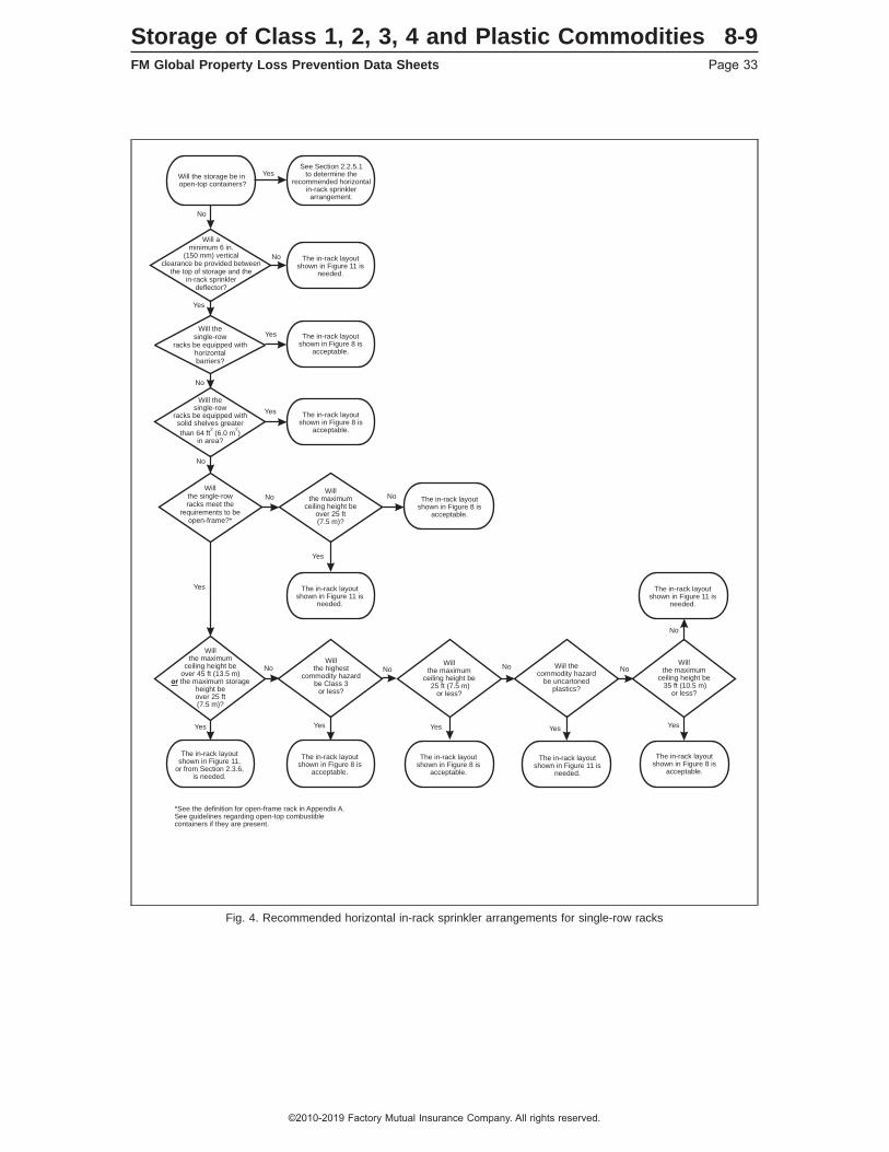
Fig. 4. Recommended horizontal in-rack sprinkler arrangements for single-row racks
Will aminimum 6 in.
(150 mm) verticalclearance be provided between
the top of storage and thein-rack sprinkler
deflector?
*See the definition for open-frame rack in Appendix A.See guidelines regarding open-top combustiblecontainers if they are present.
No
No
No
No
No No NoNo
No
No
No
Yes
Yes
Yes
Yes
Yes
Yes Yes YesYesYes
YesWill the
single-rowracks be equipped with
horizontalbarriers?
Willthe single-rowracks meet the
requirements to beopen-frame?*
Willthe maximum
ceiling height beover 45 ft (13.5 m)the maximum storage
height beover 25 ft(7.5 m)?
or
Willthe highest
commodity hazardbe Class 3
or less?
Willthe maximum
ceiling height beover 25 ft(7.5 m)?
Willthe maximum
ceiling height be25 ft (7.5 m)
or less?
Willthe maximum
ceiling height be35 ft (10.5 m)
or less?
Wiil thecommodity hazard
be uncartonedplastics?
Will thesingle-row
racks be equipped withsolid shelves greater
than 64 ft (6.0 m )in area?
2 2
Will the storage be inopen-top containers?
See Section 2.2.5.1to determine the
recommended horizontalin-rack sprinklerarrangement.
The in-rack layoutshown in Figure 11 is
needed.
The in-rack layoutshown in Figure 11,
or from Section 2.3.6,is needed.
The in-rack layoutshown in Figure 11 is
needed.
The in-rack layoutshown in Figure 11 is
needed.
The in-rack layoutshown in Figure 11 is
needed.
The in-rack layoutshown in Figure 8 is
acceptable.
The in-rack layoutshown in Figure 8 is
acceptable.
The in-rack layoutshown in Figure 8 is
acceptable.
The in-rack layoutshown in Figure 8 is
acceptable.
The in-rack layoutshown in Figure 8 is
acceptable.
The in-rack layoutshown in Figure 8 is
acceptable.
Storage of Class 1, 2, 3, 4 and Plastic Commodities 8-9FM Global Property Loss Prevention Data Sheets Page 33
©2010-2019 Factory Mutual Insurance Company. All rights reserved.
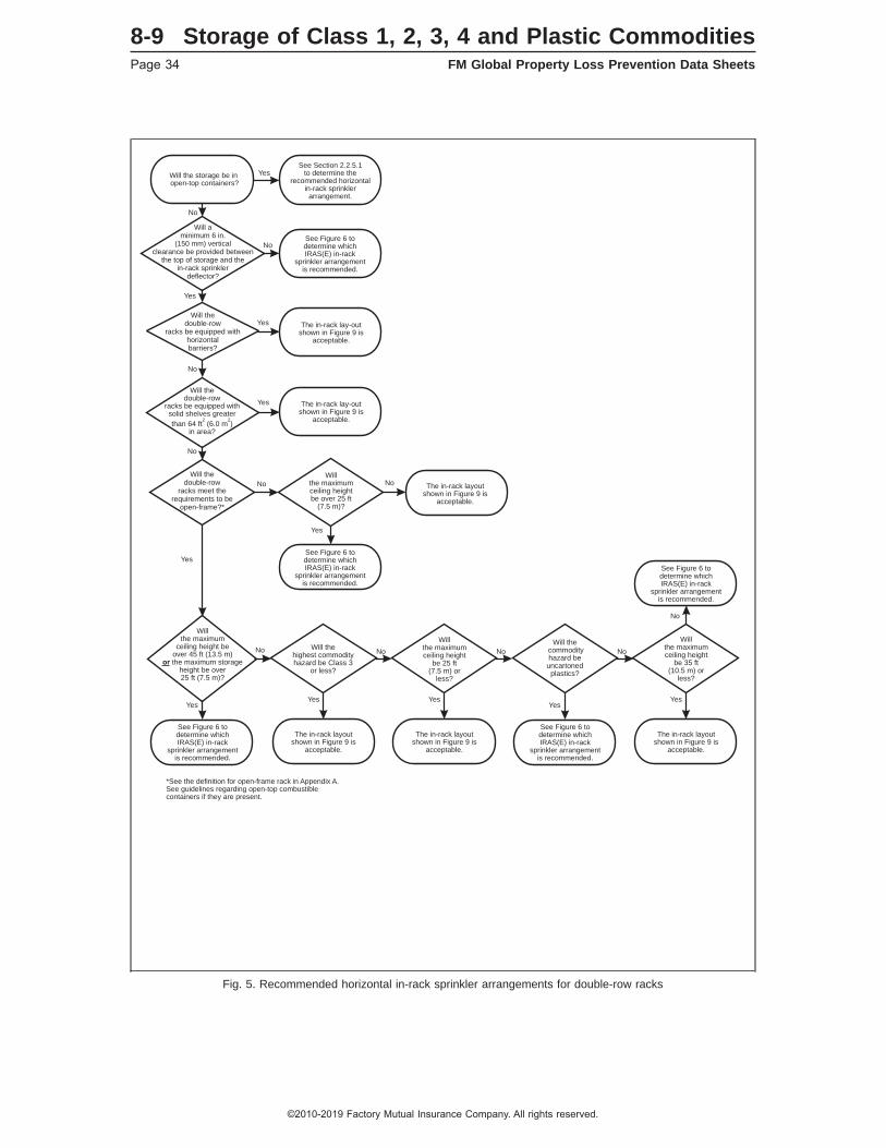
Fig. 5. Recommended horizontal in-rack sprinkler arrangements for double-row racks
*See the definition for open-frame rack in Appendix A.See guidelines regarding open-top combustiblecontainers if they are present.
No
No
No
No No No No
No
No
Yes
Yes
Yes YesYes Yes Yes
Yes
YesWill the
double-rowracks be equipped with
horizontalbarriers?
Will thedouble-row
racks meet therequirements to be
open-frame?*
Will thecommodityhazard beuncartoned
plastics?
Will thehighest commodityhazard be Class 3
or less?
Willthe maximumceiling heightbe over 25 ft
(7.5 m)?
Willthe maximumceiling height
be 25 ft(7.5 m) or
less?
Willthe maximumceiling height
be 35 ft(10.5 m) or
less?
Willthe maximum
ceiling height beover 45 ft (13.5 m)the maximum storage
height be over25 ft (7.5 m)?
or
Will thedouble-row
racks be equipped withsolid shelves greater
than 64 ft (6.0 m )in area?
2 2
See Figure 6 todetermine whichIRAS(E) in-rack
sprinkler arrangementis recommended.
See Figure 6 todetermine whichIRAS(E) in-rack
sprinkler arrangementis recommended.
See Figure 6 todetermine whichIRAS(E) in-rack
sprinkler arrangementis recommended.
See Figure 6 todetermine whichIRAS(E) in-rack
sprinkler arrangementis recommended.
See Figure 6 todetermine whichIRAS(E) in-rack
sprinkler arrangementis recommended.
The in-rack lay-outshown in Figure 9 is
acceptable.
The in-rack lay-outshown in Figure 9 is
acceptable.
The in-rack layoutshown in Figure 9 is
acceptable.
The in-rack layoutshown in Figure 9 is
acceptable.
The in-rack layoutshown in Figure 9 is
acceptable.
The in-rack layoutshown in Figure 9 is
acceptable.
Will aminimum 6 in.
(150 mm) verticalclearance be provided between
the top of storage and thein-rack sprinkler
deflector?
No
No
Yes
Yes
Will the storage be inopen-top containers?
See Section 2.2.5.1to determine the
recommended horizontalin-rack sprinklerarrangement.
8-9 Storage of Class 1, 2, 3, 4 and Plastic CommoditiesPage 34 FM Global Property Loss Prevention Data Sheets
©2010-2019 Factory Mutual Insurance Company. All rights reserved.

Fig. 6. Recommended horizontal IRAS(E) in-rack sprinkler arrangements for double-row racks
No
No
No
Yes
Yes
Yes
Will thedouble-row
racks be equipped withhorizontalbarriers?
Will themaximum ceiling
height be less thanor equal to 30 ft
(9.0 m)?
Will the double-rowracks be equipped withsolid shelves greater
than 64 ft (6.0 m )in area?
2 2
The in-rack layoutshown in Figure 12 is
acceptable.
The in-rack layoutshown in Figure 12 is
acceptable.
The in-rack layoutshown in Figure 12 is
acceptable.
The in-rack layoutshown in Figure 13,
or from Section 2.3.6,is needed.
Storage of Class 1, 2, 3, 4 and Plastic Commodities 8-9FM Global Property Loss Prevention Data Sheets Page 35
©2010-2019 Factory Mutual Insurance Company. All rights reserved.
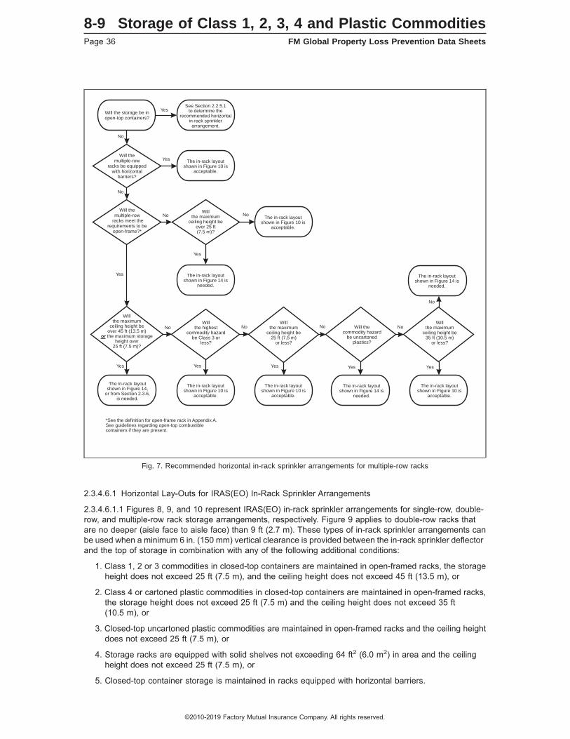
2.3.4.6.1 Horizontal Lay-Outs for IRAS(EO) In-Rack Sprinkler Arrangements
2.3.4.6.1.1 Figures 8, 9, and 10 represent IRAS(EO) in-rack sprinkler arrangements for single-row, double-row, and multiple-row rack storage arrangements, respectively. Figure 9 applies to double-row racks thatare no deeper (aisle face to aisle face) than 9 ft (2.7 m). These types of in-rack sprinkler arrangements canbe used when a minimum 6 in. (150 mm) vertical clearance is provided between the in-rack sprinkler deflectorand the top of storage in combination with any of the following additional conditions:
1. Class 1, 2 or 3 commodities in closed-top containers are maintained in open-framed racks, the storageheight does not exceed 25 ft (7.5 m), and the ceiling height does not exceed 45 ft (13.5 m), or
2. Class 4 or cartoned plastic commodities in closed-top containers are maintained in open-framed racks,the storage height does not exceed 25 ft (7.5 m) and the ceiling height does not exceed 35 ft(10.5 m), or
3. Closed-top uncartoned plastic commodities are maintained in open-framed racks and the ceiling heightdoes not exceed 25 ft (7.5 m), or
4. Storage racks are equipped with solid shelves not exceeding 64 ft2 (6.0 m2) in area and the ceilingheight does not exceed 25 ft (7.5 m), or
5. Closed-top container storage is maintained in racks equipped with horizontal barriers.
Fig. 7. Recommended horizontal in-rack sprinkler arrangements for multiple-row racks
*See the definition for open-frame rack in Appendix A.See guidelines regarding open-top combustiblecontainers if they are present.
No
No
No
No No No
No
No
No
Yes
Yes
Yes
Yes Yes YesYesYes
Yes
Will themultiple-row
racks be equippedwith horizontal
barriers?
Will the storage be inopen-top containers?
Will themultiple-row
racks meet therequirements to be
open-frame?*
Willthe maximum
ceiling height beover 45 ft (13.5 m)the maximum storage
height over25 ft (7.5 m)?
or
Willthe highest
commodity hazardbe Class 3 or
less?
Will thecommodity hazard
be uncartonedplastics?
Willthe maximum
ceiling height beover 25 ft(7.5 m)?
Willthe maximum
ceiling height be25 ft (7.5 m)
or less?
Willthe maximum
ceiling height be35 ft (10.5 m)
or less?
The in-rack layoutshown in Figure 14 is
needed.
The in-rack layoutshown in Figure 14 is
needed.
The in-rack layoutshown in Figure 14 is
needed.
The in-rack layoutshown in Figure 10 is
acceptable.
See Section 2.2.5.1to determine the
recommended horizontalin-rack sprinklerarrangement.
The in-rack layoutshown in Figure 10 is
acceptable.
The in-rack layoutshown in Figure 10 is
acceptable.
The in-rack layoutshown in Figure 10 is
acceptable.
The in-rack layoutshown in Figure 10 is
acceptable.
The in-rack layoutshown in Figure 14,
or from Section 2.3.6,is needed.
8-9 Storage of Class 1, 2, 3, 4 and Plastic CommoditiesPage 36 FM Global Property Loss Prevention Data Sheets
©2010-2019 Factory Mutual Insurance Company. All rights reserved.
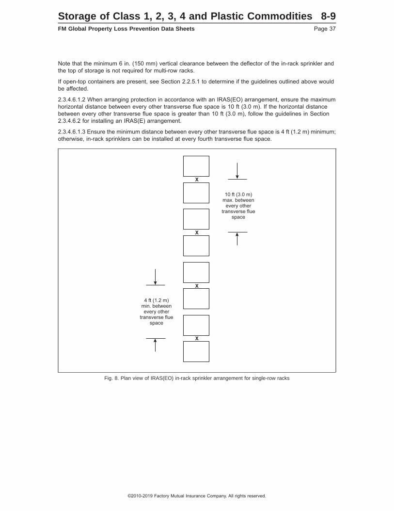
Note that the minimum 6 in. (150 mm) vertical clearance between the deflector of the in-rack sprinkler andthe top of storage is not required for multi-row racks.
If open-top containers are present, see Section 2.2.5.1 to determine if the guidelines outlined above wouldbe affected.
2.3.4.6.1.2 When arranging protection in accordance with an IRAS(EO) arrangement, ensure the maximumhorizontal distance between every other transverse flue space is 10 ft (3.0 m). If the horizontal distancebetween every other transverse flue space is greater than 10 ft (3.0 m), follow the guidelines in Section2.3.4.6.2 for installing an IRAS(E) arrangement.
2.3.4.6.1.3 Ensure the minimum distance between every other transverse flue space is 4 ft (1.2 m) minimum;otherwise, in-rack sprinklers can be installed at every fourth transverse flue space.
Fig. 8. Plan view of IRAS(EO) in-rack sprinkler arrangement for single-row racks
Storage of Class 1, 2, 3, 4 and Plastic Commodities 8-9FM Global Property Loss Prevention Data Sheets Page 37
©2010-2019 Factory Mutual Insurance Company. All rights reserved.

Fig. 9. Plan view of IRAS(EO) in-rack sprinkler arrangement for double-row racks
8-9 Storage of Class 1, 2, 3, 4 and Plastic CommoditiesPage 38 FM Global Property Loss Prevention Data Sheets
©2010-2019 Factory Mutual Insurance Company. All rights reserved.

Fig. 10. Plan view of IRAS(EO) in-rack sprinkler arrangement for multiple-row racks
4 ft (1.2 m)min. betweenevery other
transverse fluespace
10 ft (3.0 m)max. between
every othertransverse flue
space
LoadingAisle
LoadingAisle
X X X
X X X
X X X
X
X
X
X
X
X
X
X
X
X
X
X
X
X
X
X
X
X
X
X
X X X
Storage of Class 1, 2, 3, 4 and Plastic Commodities 8-9FM Global Property Loss Prevention Data Sheets Page 39
©2010-2019 Factory Mutual Insurance Company. All rights reserved.
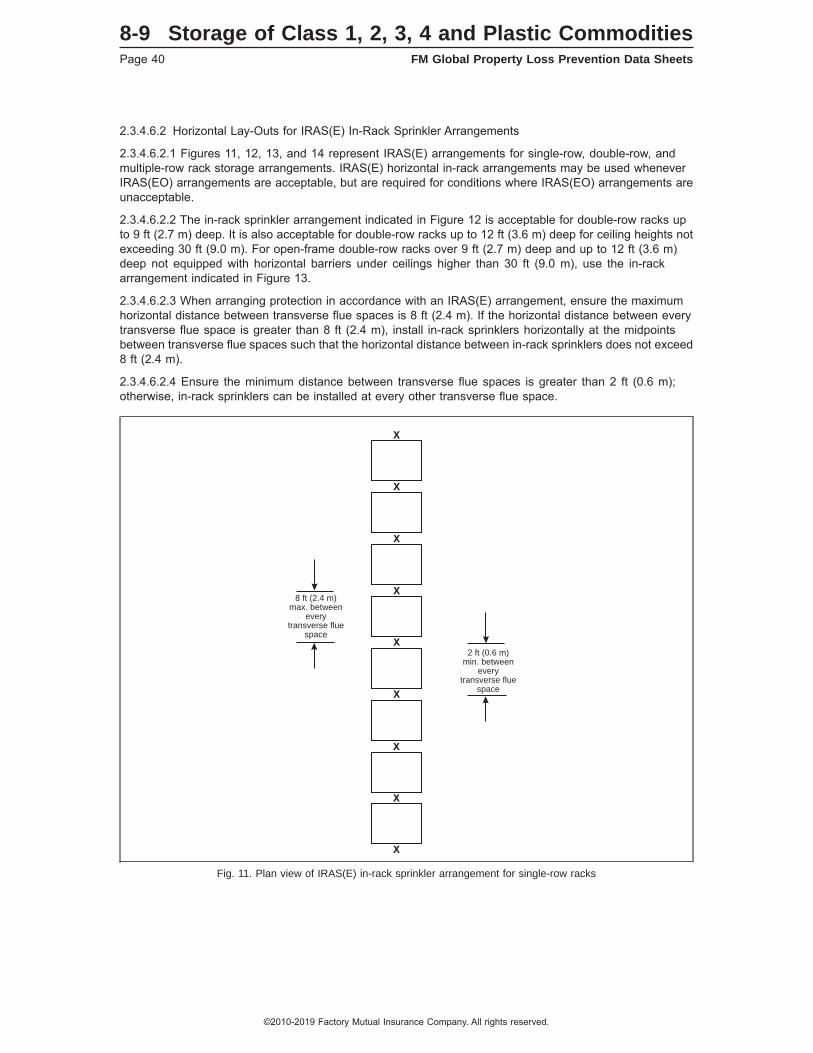
2.3.4.6.2 Horizontal Lay-Outs for IRAS(E) In-Rack Sprinkler Arrangements
2.3.4.6.2.1 Figures 11, 12, 13, and 14 represent IRAS(E) arrangements for single-row, double-row, andmultiple-row rack storage arrangements. IRAS(E) horizontal in-rack arrangements may be used wheneverIRAS(EO) arrangements are acceptable, but are required for conditions where IRAS(EO) arrangements areunacceptable.
2.3.4.6.2.2 The in-rack sprinkler arrangement indicated in Figure 12 is acceptable for double-row racks upto 9 ft (2.7 m) deep. It is also acceptable for double-row racks up to 12 ft (3.6 m) deep for ceiling heights notexceeding 30 ft (9.0 m). For open-frame double-row racks over 9 ft (2.7 m) deep and up to 12 ft (3.6 m)deep not equipped with horizontal barriers under ceilings higher than 30 ft (9.0 m), use the in-rackarrangement indicated in Figure 13.
2.3.4.6.2.3 When arranging protection in accordance with an IRAS(E) arrangement, ensure the maximumhorizontal distance between transverse flue spaces is 8 ft (2.4 m). If the horizontal distance between everytransverse flue space is greater than 8 ft (2.4 m), install in-rack sprinklers horizontally at the midpointsbetween transverse flue spaces such that the horizontal distance between in-rack sprinklers does not exceed8 ft (2.4 m).
2.3.4.6.2.4 Ensure the minimum distance between transverse flue spaces is greater than 2 ft (0.6 m);otherwise, in-rack sprinklers can be installed at every other transverse flue space.
Fig. 11. Plan view of IRAS(E) in-rack sprinkler arrangement for single-row racks
2 ft (0.6 m)min. between
everytransverse flue
space
8 ft (2.4 m)max. between
everytransverse flue
space
X
X
X
X
X
X
X
X
X
8-9 Storage of Class 1, 2, 3, 4 and Plastic CommoditiesPage 40 FM Global Property Loss Prevention Data Sheets
©2010-2019 Factory Mutual Insurance Company. All rights reserved.
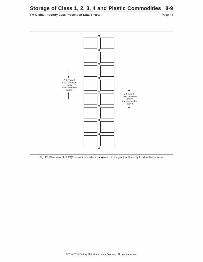
Fig. 12. Plan view of IRAS(E) in-rack sprinkler arrangement in longitudinal flue only for double-row racks
8 ft (2.4 m)max. between
everytransverse flue
space
2 ft (0.6 m)min. between
everytransverse flue
space
X
X
X
X
X
X
X
X
X
Storage of Class 1, 2, 3, 4 and Plastic Commodities 8-9FM Global Property Loss Prevention Data Sheets Page 41
©2010-2019 Factory Mutual Insurance Company. All rights reserved.
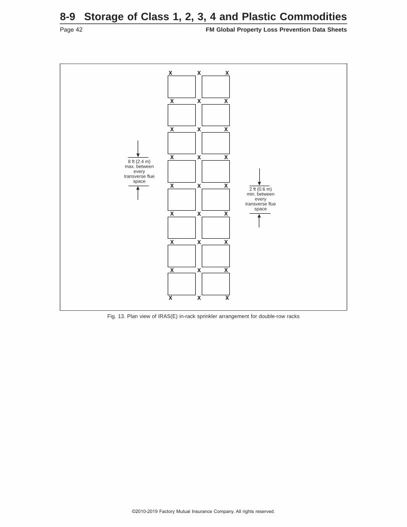
Fig. 13. Plan view of IRAS(E) in-rack sprinkler arrangement for double-row racks
8 ft (2.4 m)max. between
everytransverse flue
space
2 ft (0.6 m)min. between
everytransverse flue
space
X
X
X
X
X
X
X
X
X
X
X
X
X
X
X
X
X
X
X
X
X
X
X
X
X
X
X
8-9 Storage of Class 1, 2, 3, 4 and Plastic CommoditiesPage 42 FM Global Property Loss Prevention Data Sheets
©2010-2019 Factory Mutual Insurance Company. All rights reserved.
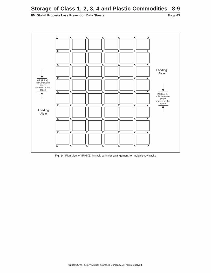
Fig. 14. Plan view of IRAS(E) in-rack sprinkler arrangement for multiple-row racks
2 ft (0.6 m)min. between
everytransverse flue
space
8 ft (2.4 m)max. between
everytransverse flue
space
X
X
X
X
X
X
X
X
X
X
X
X
X
X
X X X XXXX
X X X XXXX
X X X XXXX
X X X XXXX
X X X XXXX
XXX XXX
X XX X X X
X
X
LoadingAisle
LoadingAisle
Storage of Class 1, 2, 3, 4 and Plastic Commodities 8-9FM Global Property Loss Prevention Data Sheets Page 43
©2010-2019 Factory Mutual Insurance Company. All rights reserved.

2.3.4.6.3 Horizontal Lay-Outs for In-Rack Sprinklers in Combination With Horizontal Barriers
The use of a horizontal barrier generally reduces the number of in-rack sprinklers required per level; however,it does not reduce the number of in-rack levels required.
2.3.4.6.3.1 Use the following figures when installing horizontal barriers in combination with in-rack sprinklers:
• Figure 8: Single-row racks that (1) contain storage in closed-top containers, and (2) have a minimum6 in. (150 mm) vertical clearance between the deflector of the in-rack sprinkler and the top of storage.
• Figure 9: Double-row racks that (1) contain storage in closed-top containers, and (2) have a minimum6 in. (150 mm) vertical clearance between the deflector of the in-rack sprinkler and the top of storage.
• Figure 10: All multiple-row racks arrangements except as restricted per Section 2.2.5.1 for open-topcontainers..
• Figure 11: Single-row racks that (1) contain open-top combustible containers or (2) do not have a minimum6 in. (150 mm) vertical clearance between the deflector of the in-rack sprinkler and the top of storage.Note that for these two given conditions, there is no difference in the horizontal in-rack sprinklerarrangement between racks equipped with horizontal barriers and those that are not.
• Figure 12: Double-row racks that do not have a minimum 6 in. (150 mm) vertical clearance between thedeflector of the in-rack sprinkler and the top of closed-top container storage.
• Figure 13: Double-row racks that contain open-top combustible containers, except as modified per Section2.2.5.1. Note that for this given condition, there is no difference in the horizontal in-rack sprinklerarrangement between racks equipped with horizontal barriers and those that are not.
• Figure 14: Multiple-row racks that contain open-top combustible containers, except as modified per Section2.2.5.1. Note that for this given condition, there is no difference in the horizontal in-rack sprinklerarrangement between racks equipped with horizontal barriers and those that are not.
2.3.4.6.3.2 When installed in combination with a horizontal barrier, in-rack sprinklers do not have to bepositioned relative to the proximity of the transverse flue spaces unless (1) there is less than 6 in. (150 mm)clearance between the top of storage and deflector of the in-rack sprinkler, or (2) the hazard of open-topcontainers is present within the storage rack.
2.3.4.6.3.3 If open-top noncombustible containers are present in either single-row or double-row racks, andthey meet one of the conditions outlined in Section 2.2.5.1.1, the in-rack sprinkler arrangement shown ineither Figure 8 or 9 can be used as long as a minimum 6 in. (150 mm) vertical clearance is provided betweenthe in-rack sprinkler deflector and the top of storage. Otherwise, the in-rack arrangement in either Figure11 or 12 is needed when open-top noncombustible containers are present.
2.3.4.7 Vertical Increments of In-Rack Sprinklers
The maximum vertical increments at which in-rack sprinklers can be installed are dependent mainly oncommodity hazard and, if present, the size of solid shelves.
Note that in addition to the maximum vertical increments described below, the storage height above the toplevel of in-rack sprinklers must be limited to a maximum of 10 ft (3.0 m) unless indicated otherwise in thisdata sheet.
See Figure 15 for a flowchart summarizing the recommended vertical increments for in-rack sprinklers.
8-9 Storage of Class 1, 2, 3, 4 and Plastic CommoditiesPage 44 FM Global Property Loss Prevention Data Sheets
©2010-2019 Factory Mutual Insurance Company. All rights reserved.
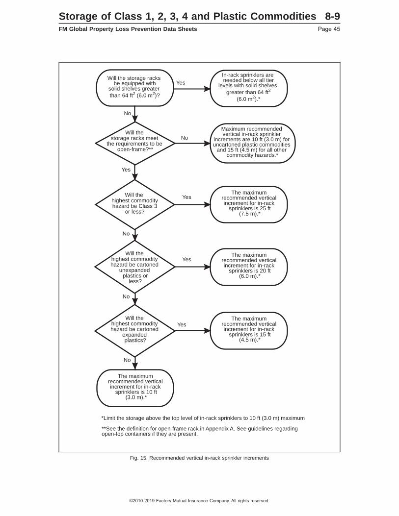
Fig. 15. Recommended vertical in-rack sprinkler increments
**See the definition for open-frame rack in Appendix A. See guidelines regarding open-top containers if they are present.
*Limit the storage above the top level of in-rack sprinklers to 10 ft (3.0 m) maximum
Yes
Yes
Yes
No
Yes
No
No
No
No
Yes
Will the storage racks meet
the requirements to be open-frame?**
Will the highest commodityhazard be Class 3
or less?
Will the highest commodity hazard be cartoned
unexpanded plastics or
less?
Will the highest commodity hazard be cartoned
expanded plastics?
The maximum recommended vertical increment for in-rack
sprinklers is 10 ft(3.0 m).*
The maximum recommended vertical increment for in-rack
sprinklers is 25 ft(7.5 m).*
The maximum recommended vertical increment for in-rack
sprinklers is 20 ft(6.0 m).*
The maximum recommended vertical increment for in-rack
sprinklers is 15 ft(4.5 m).*
Will the storage racks be equipped with
solid shelves greater
than 64 ft2 (6.0 m2)?
In-rack sprinklers are needed below all tier
levels with solid shelves
greater than 64 ft2
(6.0 m2).*
Maximum recommended vertical in-rack sprinkler
increments are 10 ft (3.0 m) for uncartoned plastic commodities
and 15 ft (4.5 m) for all other commodity hazards.*
Storage of Class 1, 2, 3, 4 and Plastic Commodities 8-9FM Global Property Loss Prevention Data Sheets Page 45
©2010-2019 Factory Mutual Insurance Company. All rights reserved.
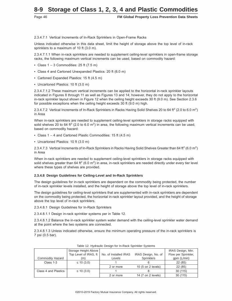
2.3.4.7.1 Vertical Increments of In-Rack Sprinklers in Open-Frame Racks
Unless indicated otherwise in this data sheet, limit the height of storage above the top level of in-racksprinklers to a maximum of 10 ft (3.0 m).
2.3.4.7.1.1 When in-rack sprinklers are needed to supplement ceiling-level sprinklers in open-frame storageracks, the following maximum vertical increments can be used, based on commodity hazard:
• Class 1 – 3 Commodities: 25 ft (7.5 m)
• Class 4 and Cartoned Unexpanded Plastics: 20 ft (6.0 m)
• Cartoned Expanded Plastics: 15 ft (4.5 m)
• Uncartoned Plastics: 10 ft (3.0 m)
2.3.4.7.1.2 These maximum vertical increments can be applied to the horizontal in-rack sprinkler layoutsindicated in Figures 8 through 11 as well as Figures 13 and 14; however, they do not apply to the horizontalin-rack sprinkler layout shown in Figure 12 when the ceiling height exceeds 30 ft (9.0 m). See Section 2.3.6for possible exceptions when the ceiling height exceeds 30 ft (9.0 m) high.
2.3.4.7.2 Vertical Increments of In-Rack Sprinklers in Racks Having Solid Shelves 20 to 64 ft2 (2.0 to 6.0 m2)in Area
When in-rack sprinklers are needed to supplement ceiling-level sprinklers in storage racks equipped withsolid shelves 20 to 64 ft2 (2.0 to 6.0 m2) in area, the following maximum vertical increments can be used,based on commodity hazard:
• Class 1 – 4 and Cartoned Plastic Commodities: 15 ft (4.5 m)
• Uncartoned Plastics: 10 ft (3.0 m)
2.3.4.7.3 Vertical Increments of In-Rack Sprinklers in Racks Having Solid Shelves Greater than 64 ft2 (6.0 m2)in Area
When in-rack sprinklers are needed to supplement ceiling-level sprinklers in storage racks equipped withsolid shelves greater than 64 ft2 (6.0 m2) in area, in-rack sprinklers are needed directly under every tier levelwhere these types of shelves are provided.
2.3.4.8 Design Guidelines for Ceiling-Level and In-Rack Sprinklers
The design guidelines for in-rack sprinklers are dependent on the commodity being protected, the numberof in-rack sprinkler levels installed, and the height of storage above the top level of in-rack sprinklers.
The design guidelines for ceiling-level sprinklers that are supplemented with in-rack sprinklers are dependenton the commodity being protected, the horizontal in-rack sprinkler layout provided, and the height of storageabove the top level of in-rack sprinklers.
2.3.4.8.1 Design Guidelines for In-Rack Sprinklers
2.3.4.8.1.1 Design in-rack sprinkler systems per in Table 12.
2.3.4.8.1.2 Balance the in-rack sprinkler system water demand with the ceiling-level sprinkler water demandat the point where the two systems are connected.
2.3.4.8.1.3 Unless indicated otherwise, ensure the minimum operating pressure of the in-rack sprinklers is7 psi (0.5 bar).
Table 12. Hydraulic Design for In-Rack Sprinkler Systems
Commodity Hazard
Storage Height AboveTop Level of IRAS, ft
(m)No. of Installed IRAS
LevelsIRAS Design, No. of
Sprinklers
IRAS Design, Min.Flow per Sprinkler,
gpm (L/min)Class 1-3 ≤ 10 (3.0) 1 6 22 (85)
2 or more 10 (5 on 2 levels) 22 (85)Class 4 and Plastics ≤ 10 (3.0) 1 8 30 (115)
2 or more 14 (7 on 2 levels) 30 (115)
8-9 Storage of Class 1, 2, 3, 4 and Plastic CommoditiesPage 46 FM Global Property Loss Prevention Data Sheets
©2010-2019 Factory Mutual Insurance Company. All rights reserved.

2.3.4.8.1.4 Unless indicated otherwise in this data sheet, the maximum water delivery time for any dry-typein-rack sprinkler system is 60 seconds and is based on the operation of the hydraulically most remote in-racksprinkler.
2.3.4.8.2 Design Guidelines for Ceiling-Level Sprinklers in Combination with In-Rack Sprinklers
2.3.4.8.2.1 Design ceiling-level sprinkler systems that are supplemented with in-rack sprinklers perTable 13. The last column of this table indicates the ceiling height to be used from the protection table (i.e.,Tables 7-11) that is applicable to the commodity hazard being protected and the in-rack sprinkler arrangementthat is being installed.
Table 13. Hydraulic Design for Ceiling-Level Sprinkler Systems Supplemented with In-Rack Sprinklers
Commodity HazardIRAS
Arrangement
Storage HeightAbove Top IRAS
Level, ft (m)Clearance Between Top of
Storage and Ceiling*
Ceiling Height forApplicable Protection
Table, ft (m)*Class 1 - 3 IRAS(EO) Up to 10 (3.0) Up to 20 (6.0) 20 (6.0)
IRAS(E) Up to 10 (3.0) Up to 20 (6.0) 20 (6.0)Class 4, Cartoned
Unexpanded Plasticand Cartoned
Expanded Plastic
IRAS(EO),IRAS(E)
Up to 5 (1.5) Up to 20 (6.0) 15 (4.5)Over 5 (1.5) up to 10
(3.0)Up to 5 (1.5) 15 (4.5)
Over 5 (1.5) up to 10 (3.0) 20 (6.0)Over 10 (3.0) up to 20 (6.0) 25 (7.5)
UncartonedUnexpanded Plastic
IRAS(EO) Up to 5 (1.5) Up to 5 (1.5) 5 (1.5)Over 5 (1.5) up to 10 (3.0) 8 (2.4)
Over 10 (3.0) up to 20 (6.0) 10 (3.0)Over 5 (1.5) up to 10
(3.0)Up to 5 (1.5) 10 (3.0)
Over 5 (1.5) up to 10 (3.0) 12 (3.6)Over 10 (3.0) up to 20 (6.0) 15 (4.5)
IRAS(E) Up to 5 (1.5) Up to 10 (3.0) 5 (1.5)Over 10 (3.0) up to 20 (6.0) 8 (2.4)
Over 5 (1.5) up to 10(3.0)
Up to 5 (1.5) 8 (2.4)Over 5 (1.5) up to 10 (3.0) 10 (3.0)
Over 10 (3.0) up to 20 (6.0) 15 (4.5)Uncartoned
Expanded PlasticIRAS(EO) Up to 5 (1.5) Up to 5 (1.5) 5 (1.5)
Over 5 (1.5) up to 10 (3.0) 8 (2.4)Over 10 (3.0) up to 20 (6.0) 10 (3.0)
Over 5(1.5) up to 10(3.0)
Up to 5 (1.5) 10 (3.0)Over 5 (1.5) up to 10 (3.0) 12 (3.6)
Over 10 (3.0) up to 20 (6.0) 20 (6.0)IRAS(E) Up to 5 (1.5) Up to 10 (3.0) 5 (1.5)
Over 10 (3.0) up to 20 (6.0) 8 (2.4)Over 5 (1.5) up to 10
(3.0)Up to 5 (1.5) 10 (3.0)
Over 5 (1.5) up to 10 (3.0) 12 (3.6)Over 10 (3.0) up to 20 (6.0) 15 (4.5)
* When this distance is greater than 20 ft (6.0 m), see Section 2.3.3.7.3 for guidance.
2.3.4.8.2.2 Use the ceiling height indicated for an IRAS(E) arrangement when in-rack sprinklers are usedin combination with horizontal barriers or when in-rack sprinklers are installed under solid shelves.
2.3.4.8.2.3 Balance the ceiling-level sprinkler system water demand with the in-rack sprinkler system waterdemand at the point where the two systems are connected.
2.3.4.9 Design Guidelines for Fire Protection Scheme 8-9A
See Appendix A, Fire Protection Scheme 8-9A, for a description of the intent of this protection arrangementas well as an example of its use.
Storage of Class 1, 2, 3, 4 and Plastic Commodities 8-9FM Global Property Loss Prevention Data Sheets Page 47
©2010-2019 Factory Mutual Insurance Company. All rights reserved.
2.3.4.9.1 Dedicated Storage Rack
Establish a dedicated storage rack (or racks) where all of the high-challenge commodities will be maintained.If this storage rack will not be solely dedicated to the storage of high-challenge commodities then either (1)extend the Fire Protection Scheme 8-9A (i.e. Scheme 8-9A) protection horizontally one pallet load in alldirections beyond the designated high-challenge commodities storage area, or (2) install a vertical barrierto segregate the high-challenge commodities from any adjacent commodities.
Commodities that can be protected by the ceiling-level sprinkler system can be stored vertically above aswell as horizontally adjacent to the portions of the storage rack equipped with Scheme 8-9A protection.
2.3.4.9.2 Horizontal Barriers
Install horizontal barriers (see Appendix A for a definition of horizontal barriers) at every tier level of thededicated storage rack if the rack is equipped with solid shelves. If the dedicated storage rack is open-frame(see Appendix A for a definition of open-frame rack storage) install horizontal barriers at vertical incrementsnot exceeding 12 ft (3.6 m). Span the barriers horizontally so that all flue spaces within the rack bay arecovered. A maximum 3 in. (75 mm) wide gap is acceptable at rack uprights.
2.3.4.9.3 In-Rack Sprinklers
Install minimum K8.0 (K115) FM Approved, quick-response sprinklers (ceiling-level or in-rack) beneath eachhorizontal barrier. Locate the deflector of the sprinkler as close to the underside of the horizontal barrier aspossible.
For single-row racks, install sprinklers at each rack upright as well as at each rack mid-bay as shown in Figure16. The maximum linear spacing between sprinklers is 5 ft (1.5 m).
For double-row racks, install sprinklers at each rack upright within the longitudinal flue space as well as atthe face of the rack. In addition, install sprinklers at the mid-bay face of each rack bay as shown in Figure 17.The maximum linear spacing between sprinklers is 5 ft (1.5 m) at the rack face and 10 ft (3.0 m) within thelongitudinal flue space.
For multiple-row racks, install an alternating IRAS(E)/IRAS(EO) sprinkler arrangement within adjacenttransverse flue spaces as shown in Figure 18. Note that sprinklers are needed at the face of each flue space.The maximum linear spacing between sprinklers using an IRAS(E) sprinkler arrangement is 5 ft (1.5 m) and10 ft (3.0 m) between sprinklers using an IRAS(EO) sprinkler arrangement.
Base the design the in-rack sprinkler system on a minimum flow of 60 gpm (230 L/min) from the most remote6 sprinklers for single-row racks or the most remote 8 sprinklers for both double-row and multiple-row racks.Include a hose demand allowance of 250 gpm (950 L/min) for manual intervention. Provide the combinedwater demand (in-rack and hose demand) for at least one hour. Note that the in-rack sprinkler demand (1)does not have to be hydraulically balanced with the ceiling-level sprinkler system, and (2) does not have tobe accounted for operating simultaneously with the ceiling-level sprinkler system.
2.3.4.9.4 Ceiling Sprinkler System
Design the ceiling-level sprinkler system as outlined in this data sheet based on the highest commodity hazardnot protected by the Scheme 8-9A protection. The sprinkler demand for Scheme 8-9A does not have to behydraulically balanced with the ceiling-level sprinkler system nor does it have to be considered operatingsimultaneously with it either.
8-9 Storage of Class 1, 2, 3, 4 and Plastic CommoditiesPage 48 FM Global Property Loss Prevention Data Sheets
©2010-2019 Factory Mutual Insurance Company. All rights reserved.

Fig. 16. Fire Protection Scheme 8-9A within single-row racks
Storage of Class 1, 2, 3, 4 and Plastic Commodities 8-9FM Global Property Loss Prevention Data Sheets Page 49
©2010-2019 Factory Mutual Insurance Company. All rights reserved.

Fig. 17. Fire Protection Scheme 8-9A within double-row racks
8-9 Storage of Class 1, 2, 3, 4 and Plastic CommoditiesPage 50 FM Global Property Loss Prevention Data Sheets
©2010-2019 Factory Mutual Insurance Company. All rights reserved.
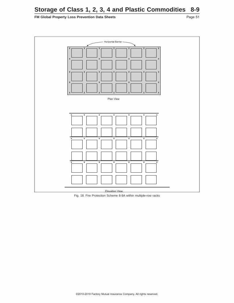
Fig. 18. Fire Protection Scheme 8-9A within multiple-row racks
Storage of Class 1, 2, 3, 4 and Plastic Commodities 8-9FM Global Property Loss Prevention Data Sheets Page 51
©2010-2019 Factory Mutual Insurance Company. All rights reserved.

2.3.5 Hose Demands, Hose Connections, and System Duration
2.3.5.1 Hose Demand and System Duration
2.3.5.1.1 See Table 14 to determine the recommended hose demand for system design purposes that accountfor potential manual intervention. Allow at least 100 gpm (380 L/min) for inside hose stream usage, whenprovided, and add the balance of the hose demand to the overall sprinkler demand at the point of connection.
2.3.5.1.2 In addition, ensure the water supplies are capable of providing the combined sprinkler system(ceiling and, if provided, in-rack) and hose demands at adequate pressure per the duration guidelines in Table14.
8-9 Storage of Class 1, 2, 3, 4 and Plastic CommoditiesPage 52 FM Global Property Loss Prevention Data Sheets
©2010-2019 Factory Mutual Insurance Company. All rights reserved.
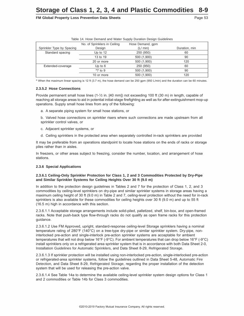
Table 14. Hose Demand and Water Supply Duration Design Guidelines
Sprinkler Type by SpacingNo. of Sprinklers in Ceiling
DesignHose Demand, gpm
(L/ min) Duration, minStandard spacing Up to 12 250 (950) 60
13 to 19 500 (1,900) 9020 or more 500 (1,900) 120
Extended-coverage Up to 6 250 (950) 60a7 to 9 500 (1,900) 90
10 or more 500 (1,900) 120a When the maximum linear spacing is 12 ft (3.7 m), the hose demand can be 250 gpm (950 L/min) and the duration can be 60 minutes.
2.3.5.2 Hose Connections
Provide permanent small hose lines (1-1⁄2 in. [40 mm]) not exceeding 100 ft (30 m) in length, capable ofreaching all storage areas to aid in potential initial-stage firefighting as well as for after-extinguishment mop-upoperations. Supply small hose lines from any of the following:
a. A separate piping system for small hose stations, or
b. Valved hose connections on sprinkler risers where such connections are made upstream from allsprinkler control valves, or
c. Adjacent sprinkler systems, or
d. Ceiling sprinklers in the protected area when separately controlled in-rack sprinklers are provided
It may be preferable from an operations standpoint to locate hose stations on the ends of racks or storagepiles rather than in aisles.
In freezers, or other areas subject to freezing, consider the number, location, and arrangement of hosestations.
2.3.6 Special Applications
2.3.6.1 Ceiling-Only Sprinkler Protection for Class 1, 2 and 3 Commodities Protected by Dry-Pipeand Similar Sprinkler Systems for Ceiling Heights Over 30 ft (9.0 m)
In addition to the protection design guidelines in Tables 2 and 7 for the protection of Class 1, 2, and 3commodities by ceiling-level sprinklers on dry-pipe and similar sprinkler systems in storage areas having amaximum ceiling height of 30 ft (9.0 m) in Table 2 and 7, ceiling-level protection without the need for in-racksprinklers is also available for these commodities for ceiling heights over 30 ft (9.0 m) and up to 55 ft(16.5 m) high in accordance with this section.
2.3.6.1.1 Acceptable storage arrangements include solid-piled, palletized, shelf, bin-box, and open-framedracks. Note that push-back type flow-through racks do not qualify as open frame racks for this protectionguidance.
2.3.6.1.2 Use FM Approved, upright, standard-response ceiling-level Storage sprinklers having a nominaltemperature rating of 280°F (140°C) on a tree-type dry-pipe or similar sprinkler system. Dry-pipe, non-interlocked pre-action and single-interlock pre-action sprinkler systems are acceptable for ambienttemperatures that will not drop below 16°F (-9°C). For ambient temperatures that can drop below 16°F (-9°C)install sprinklers only on a refrigerated area sprinkler system that is in accordance with both Data Sheet 2-0,Installation Guidelines for Automatic Sprinklers, and Data Sheet 8-29, Refrigerated Storage.
2.3.6.1.3 If sprinkler protection will be installed using non-interlocked pre-action, single-interlocked pre-actionor refrigerated-area sprinkler systems, follow the guidelines outlined in Data Sheet 5-48, Automatic FireDetection, and Data Sheet 8-29, Refrigerated Storage, regarding the proper installation of the detectionsystem that will be used for releasing the pre-action valve.
2.3.6.1.4 See Table 14a to determine the available ceiling-level sprinkler system design options for Class 1and 2 commodities or Table 14b for Class 3 commodities.
Storage of Class 1, 2, 3, 4 and Plastic Commodities 8-9FM Global Property Loss Prevention Data Sheets Page 53
©2010-2019 Factory Mutual Insurance Company. All rights reserved.

Table 14a. Ceiling-Level Sprinkler System Designs for Class 1 and 2 Commodities Protected by Dry-Pipe and SimilarSprinkler Systems
Max.Ceiling
Height, ft(m)
StorageArrangement
Ceiling-Level
Sprinkler
Min. RackAisle Width,
ft (m)
SprinklerSystem Design,
No. of AS @Min. Pressure,
psi (bar)
Max. WaterDelivery
Time
HoseDemand,
gpm (L/min)
SystemDuration,minutes
35 (10.5) Solid Piled,Palletized, Shelf,
Bin-Box
K11.2(K160)
DNA 20 @ 25 (1.7) 40 500 (1900) 120
K16.8(K240)
DNA 20 @ 10 (0.7)
K25.2(K360)
DNA 20 @ 7 (0.5)
K33.6(K480)
DNA 20 @ 50 (3.5)
40 (12.0) Solid Piled,Palletized, Shelf,
Bin-Box andOpen-Frame
Racks
K11.2(K160)
8 (2.4) 36 @ 55 (3.8) 30 500 (1900) 120
K16.8(K240)
8 (2.4) 36 @ 22 (1.5) 30 500 (1900) 120
K25.2(K360)
4 (1.2) 24 @ 15 (1.0) 25 500 (1900) 1206 (1.8) 12 @ 50 (3.5) 20 500 (1900) 90
K33.6(K480)
6 (1.8) 12 @ 50 (3.5) 20 500 (1900) 90
45 (13.5) Solid Piled,Palletized, Shelf,
Bin-Box andOpen-Frame
Racks
K25.2(K360)
6 (1.8) 12 @ 50 (3.5) 20 500 (1900) 90
K33.6(K480)
6 (1.8) 12 @ 50 (3.5) 20 500 (1900) 90
50 (15.0) Solid Piled,Palletized, Shelf,
Bin-Box andOpen-Frame
Racks
K33.6(K480)
8 (2.4) 15 @ 50 (3.5) 20 500 (1900) 90
55 (16.5) Solid Piled,Palletized, Shelf,
Bin-Box andOpen-Frame
Racks
K33.6(K480)
8 (2.4) 16 @ 50 (3.5) 20 500 (1900) 120
8-9 Storage of Class 1, 2, 3, 4 and Plastic CommoditiesPage 54 FM Global Property Loss Prevention Data Sheets
©2010-2019 Factory Mutual Insurance Company. All rights reserved.
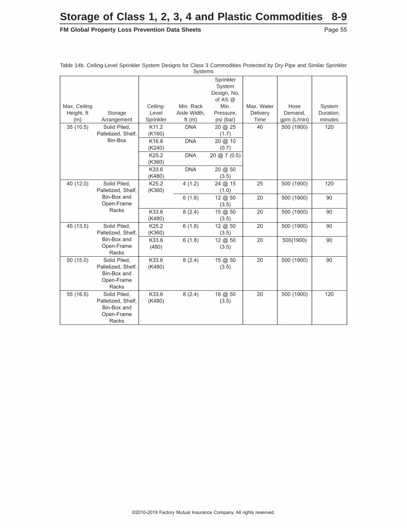
Table 14b. Ceiling-Level Sprinkler System Designs for Class 3 Commodities Protected by Dry-Pipe and Similar SprinklerSystems
Max. CeilingHeight, ft
(m)Storage
Arrangement
Ceiling-Level
Sprinkler
Min. RackAisle Width,
ft (m)
SprinklerSystem
Design, No.of AS @
Min.Pressure,psi (bar)
Max. WaterDelivery
Time
HoseDemand,
gpm (L/min)
SystemDuration,minutes
35 (10.5) Solid Piled,Palletized, Shelf,
Bin-Box
K11.2(K160)
DNA 20 @ 25(1.7)
40 500 (1900) 120
K16.8(K240)
DNA 20 @ 10(0.7)
K25.2(K360)
DNA 20 @ 7 (0.5)
K33.6(K480)
DNA 20 @ 50(3.5)
40 (12.0) Solid Piled,Palletized, Shelf,
Bin-Box andOpen-Frame
Racks
K25.2(K360)
4 (1.2) 24 @ 15(1.0)
25 500 (1900) 120
6 (1.8) 12 @ 50(3.5)
20 500 (1900) 90
K33.6(K480)
8 (2.4) 15 @ 50(3.5)
20 500 (1900) 90
45 (13.5) Solid Piled,Palletized, Shelf,
Bin-Box andOpen-Frame
Racks
K25.2(K360)
6 (1.8) 12 @ 50(3.5)
20 500 (1900) 90
K33.6(480)
6 (1.8) 12 @ 50(3.5)
20 500(1900) 90
50 (15.0) Solid Piled,Palletized, Shelf,
Bin-Box andOpen-Frame
Racks
K33.6(K480)
8 (2.4) 15 @ 50(3.5)
20 500 (1900) 90
55 (16.5) Solid Piled,Palletized, Shelf,
Bin-Box andOpen-Frame
Racks
K33.6(K480)
8 (2.4) 16 @ 50(3.5)
20 500 (1900) 120
Storage of Class 1, 2, 3, 4 and Plastic Commodities 8-9FM Global Property Loss Prevention Data Sheets Page 55
©2010-2019 Factory Mutual Insurance Company. All rights reserved.
See Section 2.3.2.5 to determine how many open remote ceiling-level sprinklers to use for the purpose ofcalculating the maximum water delivery time.
2.3.6.1.5 To achieve the maximum water delivery time indicated above in Tables 14a and 14b, experienceto date has demonstrated that the size of the sprinkler system will need to be limited to approximately 12,000ft2 (1,110 m2). Validate the maximum water delivery time before the start of any work by submitting copiesof all plans, calculations, water supply details, and equipment details to the local FM Global service office forcomputer analysis. Specific details needed for this evaluation include:
a) Manufacturer and model designation for the dry-pipe or pre-action valve
b) Manufacturer and model designation for the dry-pilot actuator, as well as response characteristics,including performance criteria that relates actuation time to air pressure setting and static water pressure
c) Air pressure to be maintained within the sprinkler piping
Note that all FM Approved pre-action and refrigerated-area sprinkler systems must be provided with all trimand accessories included as part of the Approval package. Contact the local FM Global service office beforesending the information.
2.3.6.1.6 Handle all other plan review details through normal procedures as described in Data Sheet 2-0,Installation Guidelines for Automatic Sprinklers.
2.3.6.2 Retail/Big-Box Warehouse Occupancies
Retail/big-box warehouse occupancies typically have full or partial pallet loads in the top tiers of the racks.These pallet loads are broken down as needed to replenish individual stock items in the lower tiers. Lower tiershave slatted or solid shelving, while upper tiers may have slatted, wire mesh, or open shelving. Rackarrangements with certain combinations of slatted, wire mesh, or open shelves that do not qualify as rackstorage with open shelves as described in Appendix A can nevertheless be protected as rack storage withopen shelves if they meet the conditions described in Sections 2.3.6.2.1 and 2.3.6.2.2.
2.3.6.2.1. Protect rack storage up to 20 ft (6.0 m) high as rack storage with open shelves when all of thefollowing conditions are met:
a) Slatted shelves are provided, they are fixed-in-place and provide a minimum 3 in. (75 mm) widetransverse flue space, and
b) There are no solid shelf levels above the 12 ft (3.6 m) height in the rack (although there may be otheropen shelf or wire mesh shelf levels above), and
c) Transverse flue spaces at least 3 in. (75 mm) wide are provided at least every 10 ft (3.0 m) horizontally,and
d) The storage commodity does not consist of uncartoned plastics.
2.3.6.2.2. Provide longitudinal flue spaces if slatted shelf openings and transverse flue spaces do not runcompletely through the racks.
2.3.6.2.3. If the stored commodities include aerosols or flammable or combustible liquids, adhere to therecommendations in the relevant occupancy-related data sheet.
2.3.6.3 Protection of Class 1, 2, 3, 4 and Cartoned Plastics in Open-Frame Single and Double-RowRacks Using In-Rack Sprinklers Only in the Longitudinal Flue Space
2.3.6.3.1 Class 1, 2, 3, 4 and cartoned plastic commodities maintained in single-row and double-row rackscan be protected by in-rack sprinklers in only the longitudinal flue space under the following conditions:
• The ceiling and in-rack sprinkler systems are wet-pipe only, and
• The storage racks meet the definition of open-frame, and
• The depth (aisle-to-aisle) of the double-racks does not exceed 9 ft (2.7 m), and
• The in-racks sprinklers are in accordance with Sections 2.3.4.1.1, 2.3.4.3, 2.3.4.4, and 2.3.4.5, and
• The in-rack sprinklers are installed horizontally at every transverse flue space intersection as outlined inFigure 11 for single-row racks and Figure 12 for double-row racks, and
8-9 Storage of Class 1, 2, 3, 4 and Plastic CommoditiesPage 56 FM Global Property Loss Prevention Data Sheets
©2010-2019 Factory Mutual Insurance Company. All rights reserved.
• The in-rack sprinklers are installed on vertical increments not exceeding 12 ft (3.6 m), and
• The storage height above the top in-rack sprinkler level does not exceed 10 ft (3.0 m), and
• The in-rack design is based on Table 12, and
• The ceiling design is based on Table 13, and
• The hose stream allowance and system duration are based on Table 14.
2.3.6.3.2 As an alternative to the protection outlined in Section 2.3.6.3.1, Class 1, 2, 3, 4 and cartoned plasticcommodities maintained in single-row and double-row racks can also be protected by in-rack sprinklers inonly the longitudinal flue space under the following conditions:
• The ceiling and in-rack sprinkler systems are wet-pipe only, and
• The storage racks meet the definition of open-frame, and
• The depth (aisle-to-aisle) of the double-row racks does not exceed 9 ft (2.7 m), and
• The in-rack sprinklers are quick-response and in accordance with Sections 2.3.4.1.1, 2.3.4.3, 2.3.4.4, and2.3.4.5, and
• The in-rack sprinklers are installed horizontally at every other transverse flue space intersection, as outlinedin Figure 8 for single-row racks and Figure 9 for double-row racks, and staggered vertically, and
• The in-rack sprinklers are installed on vertical increments not exceeding 12 ft (3.6 m), and
• All transverse/longitudinal flue space intersections are protected with in-rack sprinklers at verticalincrements not exceeding 24 ft (7.2 m), and
• The storage height above the top in-rack sprinkler level does not exceed 10 ft (3.0 m), and
• The in-rack design is based on Table 12, and
• The ceiling design is based on Table 13, and
• The hose stream allowance and system duration are based on Table 14.
2.3.6.4 Protection of Class 1, 2, 3, 4, Cartoned Plastics and Uncartoned Unexpanded Plastics inSingle and Double-Row Racks Using a Combination of Longitudinal In-Rack Sprinklers andHorizontal Barriers
Class 1, 2, 3, 4, cartoned plastic and uncartoned unexpanded plastic commodities maintained in single-rowand double-row racks can be protected by in-rack sprinklers in only the longitudinal flue space under thefollowing conditions:
• The storage racks are not physically equipped with solid shelves, and
• A minimum gross 3 in. (75 mm) wide space is provided between stored product, and
• A minimum net 3 in. (75 mm) wide space is provided horizontally at least every 10 ft (3.0 m), and
• The depth (aisle-to-aisle) of the double-row racks does not exceed 9 ft (2.7 m), and
• The in-rack sprinklers are quick-response and in accordance with Sections 2.3.4.1.1, 2.3.4.3, 2.3.4.4, and2.3.4.5, and
• The longitudinal in-rack sprinklers are installed horizontally on a maximum linear spacing of 5 ft (1.5 m),and
• The in-rack sprinklers are installed on vertical increments not exceeding 12 ft (3.6 m), and
• The horizontal barriers are installed above the lowest in-rack sprinkler level as well as vertically at everyother in-rack sprinkler level (i.e., first in-rack level, third in-rack level, etc.), and
• The storage height above the top in-rack sprinkler level does not exceed 10 ft (3.0 m), and
• The in-rack design is based on Table12, and
• The ceiling design is based on Table 13, and
Storage of Class 1, 2, 3, 4 and Plastic Commodities 8-9FM Global Property Loss Prevention Data Sheets Page 57
©2010-2019 Factory Mutual Insurance Company. All rights reserved.
• The hose stream allowance and system duration are based on Table 14.
2.3.6.5 Protection of Class 1, 2, 3, 4 and Unexpanded Plastics in Open-Frame Storage Racks UnderCeilings up to 45 ft (13.5 m) High Using K14.0 (K200) and Larger, Quick-Response, Pendent Ceiling-level Sprinklers
Class 1, 2, 3, 4, and unexpanded plastics (cartoned and uncartoned) can be protected by a single level ofin-rack sprinklers under the following conditions:
• The ceiling-level sprinklers are of the quick-response type, pendent orientation, standard spacing (doesnot apply to extended-coverage sprinklers) and have minimum K-factor of 14.0 (K200), and
• The storage racks meet the definition of open-frame, and
• The in-rack sprinklers are in accordance with Sections 2.3.4.1.1, 2.3.4.3, 2.3.4.4, and 2.3.4.5, and
• The in-rack sprinklers are installed horizontally at every transverse flue space intersection as outlined inFigure 11 for single-row racks, Figure 12 for double-row racks and Figure 14 for multiple-row racks (facesprinklers not required in Figure 14), and
• The in-rack sprinklers are installed vertically at a tier height that is located within the range of one-half totwo-thirds of the overall storage height, and
• The in-rack design is based on a minimum flow of 60 gpm (230 L/min) from the most remote 8 in-racksprinklers, and
• The ceiling design is obtained from the protection table for the commodity hazard being protected usinga ceiling height of 40 ft (12.0 m), and
• The hose stream allowance and system duration are based on Table 14.
2.3.6.6 Alternative In-Rack Sprinkler Designs
2.3.6.6.1 General
The in-rack sprinkler designs provided in this section are alternatives to the in-rack sprinkler designsrecommended in Section 2.3.4 of this data sheet.
2.3.6.6.2 Occupancy
The designs in this section can be used to protect all commodities addressed in this data sheet.
Do not use the in-rack sprinkler designs in this section to protect open-top containers, unless they are locatedon the bottom tier level.
Storage racks must be considered “open-frame” as defined in Appendix A.
2.3.6.6.3 Protection
2.3.6.6.3.1 In-Rack Sprinkler System
The alternative in-rack sprinkler designs in this section are for wet-pipe systems only.
2.3.6.6.3.2 In-Rack Sprinklers
Use FM Approved Storage (ceiling) sprinklers that are standard-coverage, quick-response, pendent, andhave a nominal temperature rating of 160°F (70°C). Use minimum K22.4 (K320) sprinklers; however, minimum14.0 (K200) sprinklers can be used when the required flow for the commodity being protected is 100 gpm(380 L/min) or less.
2.3.6.6.3.3 Horizontal Location of In-Rack Sprinklers
See Figures 19a, 19b, 19c, 20a, 20b and 21 for the recommended horizontal location of in-rack sprinklers,depending on the type of storage rack being protected. The minimum and maximum horizontal distancesbetween in-rack sprinklers is 27 in. (700 mm) and 4.5 ft (1.4 m), respectively, except as shown in the applicablefigures. The maximum horizontal distance between face sprinklers and either (1) the face of the storage rack,or (2) the outer edge of the pallet load if it protrudes into the aisle, is 18 in. (450 mm). Locate all in-racksprinklers within the footprint of the rack structure they are intended to protect. In-rack sprinklers protecting
8-9 Storage of Class 1, 2, 3, 4 and Plastic CommoditiesPage 58 FM Global Property Loss Prevention Data Sheets
©2010-2019 Factory Mutual Insurance Company. All rights reserved.

the flue space created between a single-row rack structure and a wall located within 12 in. (300 mm)horizontally of the rack structure can be positioned outside the footprint of the single-row rack structure asshown in Figure 19c.
Arrange sprinkler piping and in-rack sprinklers to avoid mechanical damage, but ensure proper distributionfrom the in-rack sprinkler can be achieved. Prior to installing in-rack sprinklers, check the proposed in-racksprinkler locations to ensure both adequate protection against mechanical damage and proper sprinklerdischarge are provided.
Fig. 19a. Plan view of alternative in-rack sprinkler arrangement for single-row racks up to 3 ft (0.9 m) deep
Max. 4.5 ft (1.4 m)
3 ft (0.9 m)max.
X X X XX X X
Fig. 19b. Plan view of alternative in-rack sprinkler arrangement for single-row racks up to 6 ft (1.8 m) deep
Max. 8.5 ft (2.6 m)
6 ft (1.8 m)max.
X X X X
XX X X
Fig. 19c. Plan view of alternative in-rack sprinkler arrangement for single-row racks up to 6 ft (1.8 m) deep located againstwall
Max. 8.5 ft (2.6 m)
Wall
6 ft (1.8 m)max.
1 ft (0.3 m)max.
X X X X
X X X
Fig. 20a. Plan view of alternative in-rack sprinkler arrangement for double-row racks up to 9 ft (2.7 m) deep
Max. 8.5 ft (2.6 m)
Max.9 ft (2.7 m)
X X X X
X X X X
X X X X
X X X
Storage of Class 1, 2, 3, 4 and Plastic Commodities 8-9FM Global Property Loss Prevention Data Sheets Page 59
©2010-2019 Factory Mutual Insurance Company. All rights reserved.
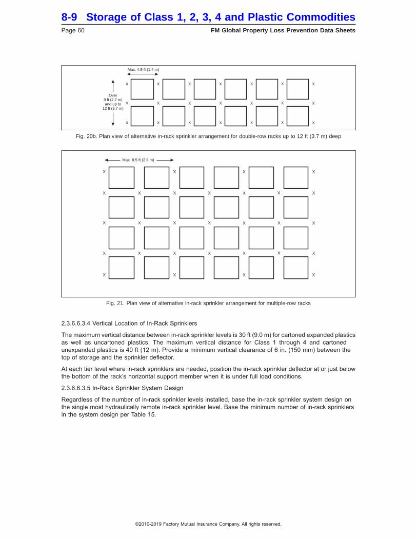
2.3.6.6.3.4 Vertical Location of In-Rack Sprinklers
The maximum vertical distance between in-rack sprinkler levels is 30 ft (9.0 m) for cartoned expanded plasticsas well as uncartoned plastics. The maximum vertical distance for Class 1 through 4 and cartonedunexpanded plastics is 40 ft (12 m). Provide a minimum vertical clearance of 6 in. (150 mm) between thetop of storage and the sprinkler deflector.
At each tier level where in-rack sprinklers are needed, position the in-rack sprinkler deflector at or just belowthe bottom of the rack’s horizontal support member when it is under full load conditions.
2.3.6.6.3.5 In-Rack Sprinkler System Design
Regardless of the number of in-rack sprinkler levels installed, base the in-rack sprinkler system design onthe single most hydraulically remote in-rack sprinkler level. Base the minimum number of in-rack sprinklersin the system design per Table 15.
Fig. 20b. Plan view of alternative in-rack sprinkler arrangement for double-row racks up to 12 ft (3.7 m) deep
Max. 4.5 ft (1.4 m)
Over9 ft (2.7 m)and up to
12 ft (3.7 m)
X X X X
X
X
X
X
X
X
X
X
X
X
X
X
X
X
X
X
X
Fig. 21. Plan view of alternative in-rack sprinkler arrangement for multiple-row racks
Max. 8.5 ft (2.6 m)
X
X
X
X
X
X
X
X
X
X
X
X
X
X
X
X
X
X
X
X X
X
X
X
X
X
X
X
X
8-9 Storage of Class 1, 2, 3, 4 and Plastic CommoditiesPage 60 FM Global Property Loss Prevention Data Sheets
©2010-2019 Factory Mutual Insurance Company. All rights reserved.
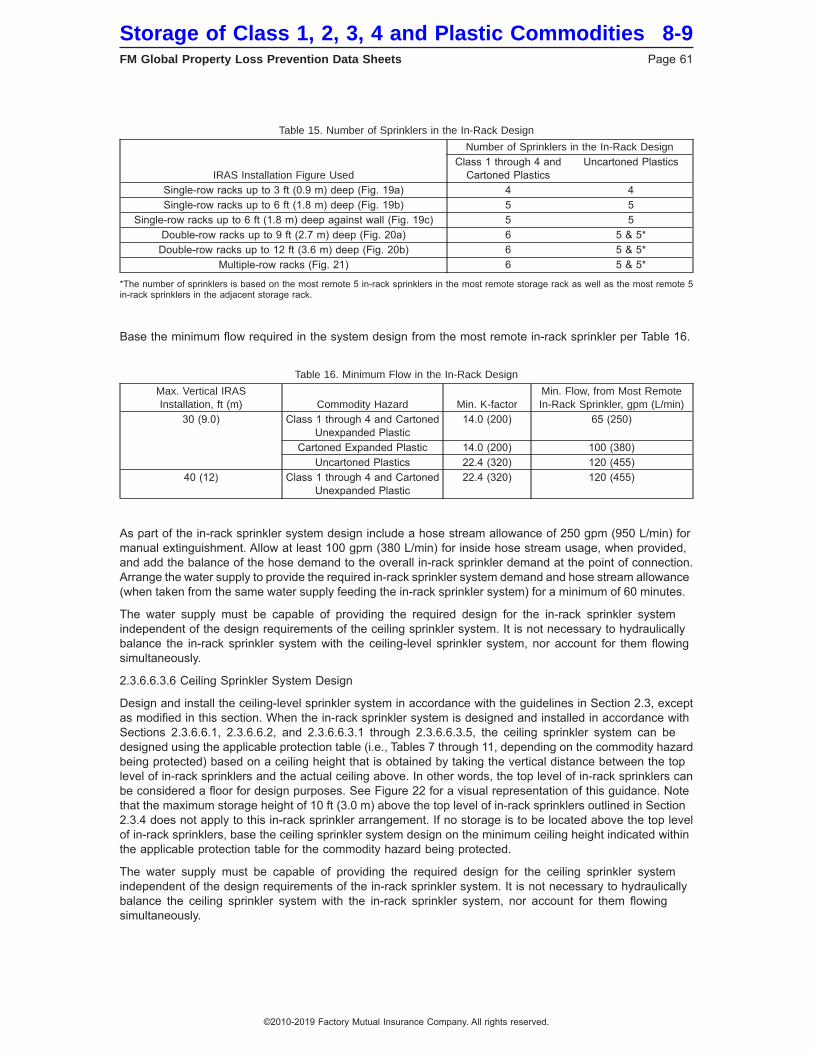
Table 15. Number of Sprinklers in the In-Rack Design
IRAS Installation Figure Used
Number of Sprinklers in the In-Rack DesignClass 1 through 4 and
Cartoned PlasticsUncartoned Plastics
Single-row racks up to 3 ft (0.9 m) deep (Fig. 19a) 4 4Single-row racks up to 6 ft (1.8 m) deep (Fig. 19b) 5 5
Single-row racks up to 6 ft (1.8 m) deep against wall (Fig. 19c) 5 5Double-row racks up to 9 ft (2.7 m) deep (Fig. 20a) 6 5 & 5*Double-row racks up to 12 ft (3.6 m) deep (Fig. 20b) 6 5 & 5*
Multiple-row racks (Fig. 21) 6 5 & 5*
*The number of sprinklers is based on the most remote 5 in-rack sprinklers in the most remote storage rack as well as the most remote 5in-rack sprinklers in the adjacent storage rack.
Base the minimum flow required in the system design from the most remote in-rack sprinkler per Table 16.
Table 16. Minimum Flow in the In-Rack Design
Max. Vertical IRASInstallation, ft (m) Commodity Hazard Min. K-factor
Min. Flow, from Most RemoteIn-Rack Sprinkler, gpm (L/min)
30 (9.0) Class 1 through 4 and CartonedUnexpanded Plastic
14.0 (200) 65 (250)
Cartoned Expanded Plastic 14.0 (200) 100 (380)Uncartoned Plastics 22.4 (320) 120 (455)
40 (12) Class 1 through 4 and CartonedUnexpanded Plastic
22.4 (320) 120 (455)
As part of the in-rack sprinkler system design include a hose stream allowance of 250 gpm (950 L/min) formanual extinguishment. Allow at least 100 gpm (380 L/min) for inside hose stream usage, when provided,and add the balance of the hose demand to the overall in-rack sprinkler demand at the point of connection.Arrange the water supply to provide the required in-rack sprinkler system demand and hose stream allowance(when taken from the same water supply feeding the in-rack sprinkler system) for a minimum of 60 minutes.
The water supply must be capable of providing the required design for the in-rack sprinkler systemindependent of the design requirements of the ceiling sprinkler system. It is not necessary to hydraulicallybalance the in-rack sprinkler system with the ceiling-level sprinkler system, nor account for them flowingsimultaneously.
2.3.6.6.3.6 Ceiling Sprinkler System Design
Design and install the ceiling-level sprinkler system in accordance with the guidelines in Section 2.3, exceptas modified in this section. When the in-rack sprinkler system is designed and installed in accordance withSections 2.3.6.6.1, 2.3.6.6.2, and 2.3.6.6.3.1 through 2.3.6.6.3.5, the ceiling sprinkler system can bedesigned using the applicable protection table (i.e., Tables 7 through 11, depending on the commodity hazardbeing protected) based on a ceiling height that is obtained by taking the vertical distance between the toplevel of in-rack sprinklers and the actual ceiling above. In other words, the top level of in-rack sprinklers canbe considered a floor for design purposes. See Figure 22 for a visual representation of this guidance. Notethat the maximum storage height of 10 ft (3.0 m) above the top level of in-rack sprinklers outlined in Section2.3.4 does not apply to this in-rack sprinkler arrangement. If no storage is to be located above the top levelof in-rack sprinklers, base the ceiling sprinkler system design on the minimum ceiling height indicated withinthe applicable protection table for the commodity hazard being protected.
The water supply must be capable of providing the required design for the ceiling sprinkler systemindependent of the design requirements of the in-rack sprinkler system. It is not necessary to hydraulicallybalance the ceiling sprinkler system with the in-rack sprinkler system, nor account for them flowingsimultaneously.
Storage of Class 1, 2, 3, 4 and Plastic Commodities 8-9FM Global Property Loss Prevention Data Sheets Page 61
©2010-2019 Factory Mutual Insurance Company. All rights reserved.
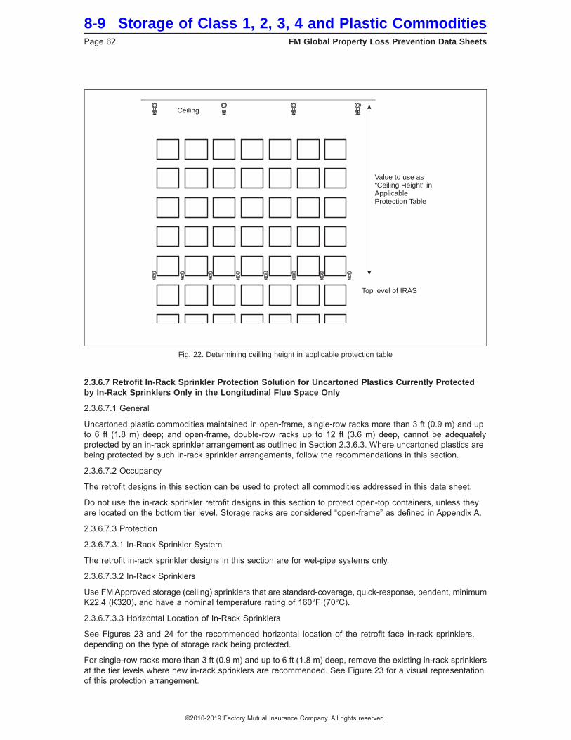
2.3.6.7 Retrofit In-Rack Sprinkler Protection Solution for Uncartoned Plastics Currently Protectedby In-Rack Sprinklers Only in the Longitudinal Flue Space Only
2.3.6.7.1 General
Uncartoned plastic commodities maintained in open-frame, single-row racks more than 3 ft (0.9 m) and upto 6 ft (1.8 m) deep; and open-frame, double-row racks up to 12 ft (3.6 m) deep, cannot be adequatelyprotected by an in-rack sprinkler arrangement as outlined in Section 2.3.6.3. Where uncartoned plastics arebeing protected by such in-rack sprinkler arrangements, follow the recommendations in this section.
2.3.6.7.2 Occupancy
The retrofit designs in this section can be used to protect all commodities addressed in this data sheet.
Do not use the in-rack sprinkler retrofit designs in this section to protect open-top containers, unless theyare located on the bottom tier level. Storage racks are considered “open-frame” as defined in Appendix A.
2.3.6.7.3 Protection
2.3.6.7.3.1 In-Rack Sprinkler System
The retrofit in-rack sprinkler designs in this section are for wet-pipe systems only.
2.3.6.7.3.2 In-Rack Sprinklers
Use FM Approved storage (ceiling) sprinklers that are standard-coverage, quick-response, pendent, minimumK22.4 (K320), and have a nominal temperature rating of 160°F (70°C).
2.3.6.7.3.3 Horizontal Location of In-Rack Sprinklers
See Figures 23 and 24 for the recommended horizontal location of the retrofit face in-rack sprinklers,depending on the type of storage rack being protected.
For single-row racks more than 3 ft (0.9 m) and up to 6 ft (1.8 m) deep, remove the existing in-rack sprinklersat the tier levels where new in-rack sprinklers are recommended. See Figure 23 for a visual representationof this protection arrangement.
Fig. 22. Determining ceililng height in applicable protection table
Ceiling
Value to use as“Ceiling Height” inApplicableProtection Table
Top level of IRAS
8-9 Storage of Class 1, 2, 3, 4 and Plastic CommoditiesPage 62 FM Global Property Loss Prevention Data Sheets
©2010-2019 Factory Mutual Insurance Company. All rights reserved.
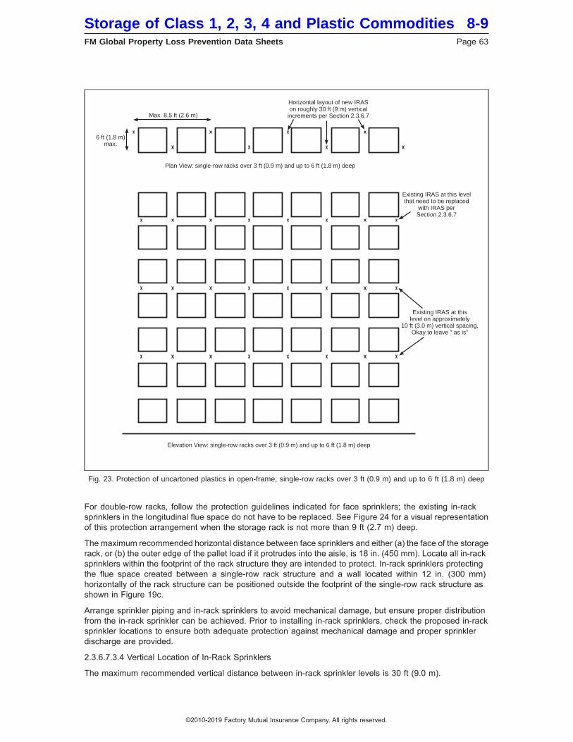
For double-row racks, follow the protection guidelines indicated for face sprinklers; the existing in-racksprinklers in the longitudinal flue space do not have to be replaced. See Figure 24 for a visual representationof this protection arrangement when the storage rack is not more than 9 ft (2.7 m) deep.
The maximum recommended horizontal distance between face sprinklers and either (a) the face of the storagerack, or (b) the outer edge of the pallet load if it protrudes into the aisle, is 18 in. (450 mm). Locate all in-racksprinklers within the footprint of the rack structure they are intended to protect. In-rack sprinklers protectingthe flue space created between a single-row rack structure and a wall located within 12 in. (300 mm)horizontally of the rack structure can be positioned outside the footprint of the single-row rack structure asshown in Figure 19c.
Arrange sprinkler piping and in-rack sprinklers to avoid mechanical damage, but ensure proper distributionfrom the in-rack sprinkler can be achieved. Prior to installing in-rack sprinklers, check the proposed in-racksprinkler locations to ensure both adequate protection against mechanical damage and proper sprinklerdischarge are provided.
2.3.6.7.3.4 Vertical Location of In-Rack Sprinklers
The maximum recommended vertical distance between in-rack sprinkler levels is 30 ft (9.0 m).
Fig. 23. Protection of uncartoned plastics in open-frame, single-row racks over 3 ft (0.9 m) and up to 6 ft (1.8 m) deep
6 ft (1.8 m)max.
Max. 8.5 ft (2.6 m)
Plan View: single-row racks over 3 ft (0.9 m) and up to 6 ft (1.8 m) deep
Elevation View: single-row racks over 3 ft (0.9 m) and up to 6 ft (1.8 m) deep
Horizontal layout of new IRASon roughly 30 ft (9 m) vertical
increments per Section 2.3.6.7
Existing IRAS at thislevel on approximately
10 ft (3.0 m) vertical spacing,Okay to leave “ as is”
Existing IRAS at this levelthat need to be replaced
with IRAS perSection 2.3.6.7
Storage of Class 1, 2, 3, 4 and Plastic Commodities 8-9FM Global Property Loss Prevention Data Sheets Page 63
©2010-2019 Factory Mutual Insurance Company. All rights reserved.
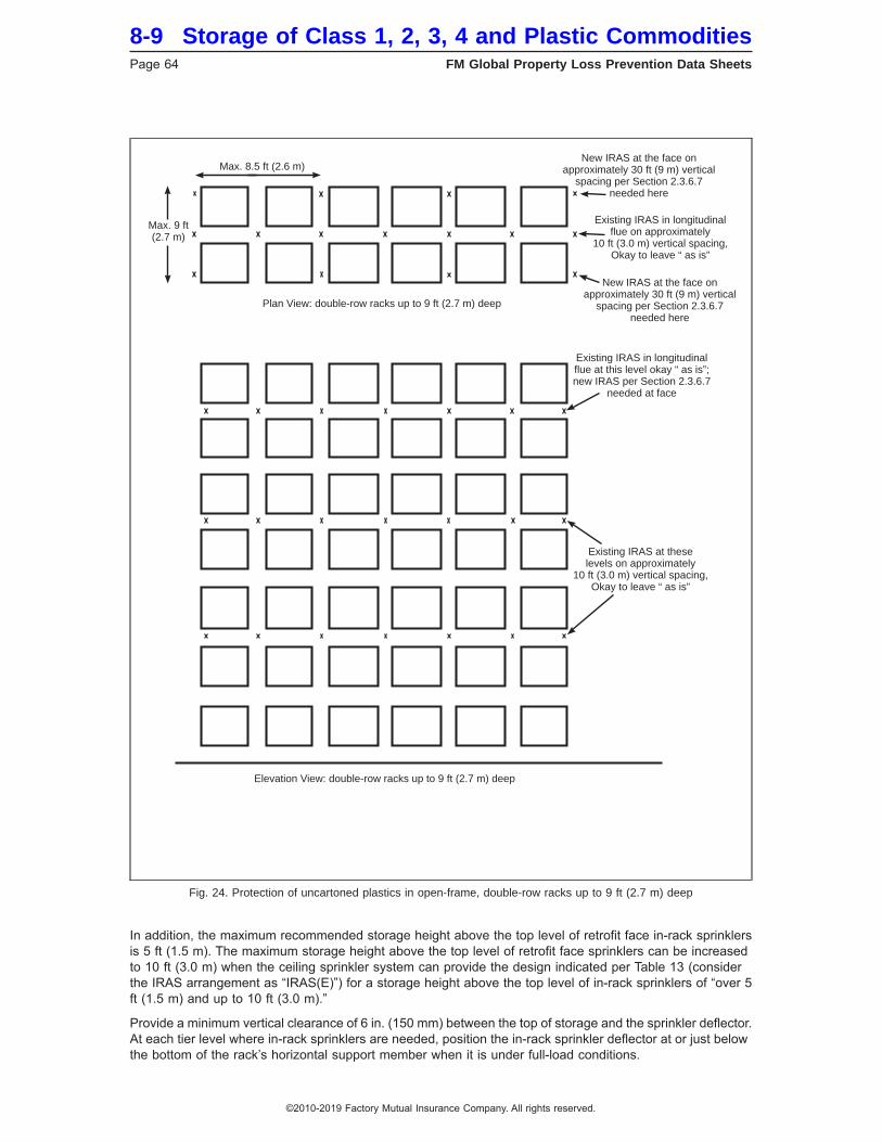
In addition, the maximum recommended storage height above the top level of retrofit face in-rack sprinklersis 5 ft (1.5 m). The maximum storage height above the top level of retrofit face sprinklers can be increasedto 10 ft (3.0 m) when the ceiling sprinkler system can provide the design indicated per Table 13 (considerthe IRAS arrangement as “IRAS(E)”) for a storage height above the top level of in-rack sprinklers of “over 5ft (1.5 m) and up to 10 ft (3.0 m).”
Provide a minimum vertical clearance of 6 in. (150 mm) between the top of storage and the sprinkler deflector.At each tier level where in-rack sprinklers are needed, position the in-rack sprinkler deflector at or just belowthe bottom of the rack’s horizontal support member when it is under full-load conditions.
Fig. 24. Protection of uncartoned plastics in open-frame, double-row racks up to 9 ft (2.7 m) deep
Max. 9 ft(2.7 m)
Max. 8.5 ft (2.6 m)
Plan View: double-row racks up to 9 ft (2.7 m) deep
Elevation View: double-row racks up to 9 ft (2.7 m) deep
New IRAS at the face onapproximately 30 ft (9 m) vertical
spacing per Section 2.3.6.7needed here
New IRAS at the face onapproximately 30 ft (9 m) vertical
spacing per Section 2.3.6.7needed here
Existing IRAS in longitudinalflue on approximately
10 ft (3.0 m) vertical spacing,Okay to leave “ as is”
Existing IRAS in longitudinalflue at this level okay “ as is”;new IRAS per Section 2.3.6.7
needed at face
Existing IRAS at theselevels on approximately
10 ft (3.0 m) vertical spacing,Okay to leave “ as is”
8-9 Storage of Class 1, 2, 3, 4 and Plastic CommoditiesPage 64 FM Global Property Loss Prevention Data Sheets
©2010-2019 Factory Mutual Insurance Company. All rights reserved.

2.3.6.7.3.5 In-Rack Sprinkler System Design
Regardless of the number of in-rack sprinkler levels installed, base the in-rack sprinkler system design onthe single most hydraulically remote in-rack sprinkler level. Base the minimum number of retrofit face in-racksprinklers in the system design per Table 17.
Base the minimum flow required from the most remote face in-rack sprinkler on a flow of 120 gpm (455 L/min).
The retrofit in-rack sprinkler design does not need to account for any existing in-rack sprinklers flowing nordoes it have to be hydraulically balanced with the existing overhead ceiling sprinkler system.
As part of the retrofit in-rack sprinkler system design, include a hose stream allowance of 250 gpm (950L/min) for manual extinguishment. Allow at least 100 gpm (380 L/min) for inside hose stream usage, whenprovided, and add the balance of the hose demand to the overall retrofit in-rack sprinkler demand at the pointof connection.
Arrange the water supply to provide the required retrofit in-rack sprinkler system demand and hose streamallowance (when taken from the same water supply feeding the in-rack sprinkler system) for a minimum of60 minutes.
2.3.6.7.3.6 Ceiling Sprinkler System Design
Determine the ceiling-level sprinkler system’s recommended design per Table 13 using an in-rack sprinklerarrangement (IRAS arrangement) of “IRAS(E).” If the existing ceiling-level sprinklers are K5.6 (K80) or K8.0(K115), or if the existing ceiling-level sprinkler system is not capable of providing the indicated ceiling designfor (a) a storage height of up to 5 ft (1.5 m), or (b) a storage height of over 5 ft (1.5 m) and up to 10 ft (3.0m), then install the recommended retrofit face sprinklers above the top of storage.
Table 17. Number of Face In-Rack Sprinklers in the Retrofit In-Rack Design
IRAS Installation Figure Used
Number of Face In-Rack Sprinklers in the RetrofitIn-Rack Design
Class 1 through 4Cartoned Plastics and
UncartonedUnexpanded Plastics
Uncartoned ExpandedPlastics
Single-row racks over 3 ft (0.9 m) and up to 6 ft (1.8 m) deep (Fig.19b)
3 4
Single-row rack over 3 ft (0.9 m) and up to 6 ft (1.8 m) deepagainst wall (Fig. 19c)
3 4
Double-row rack up to 9 ft (2.7 m) deep (Fig. 20a) 4 3 & 3 (6 total)*Double-row rack over 9 ft (2.7 m) and up to 12 ft (3.6 m) deep
(Fig. 20b)5 4 & 4 (8 total)*
*The number of sprinklers indicated is based on the most remote in-rack sprinklers in both the most remote storage rack as well as themost remote adjacent sprinkler rack.
2.3.6.8 K25.2EC (K360EC) Pendent In-Rack Sprinkler Protection of Class 1, 2, 3, 4 and CartonedUnexpanded Plastics in Open-Frame Racks in Combination with Horizontal Barriers
2.3.6.8.1 Commodity
2.3.6.8.1.1 This in-rack sprinkler protection option applies to Class 1 through 4 and cartoned unexpandedplastics only. It does not apply to cartoned expanded plastics nor any uncartoned plastics.
2.3.6.8.1.2 All storage containers must be closed top.
2.3.6.8.2 Storage Racks
2.3.6.8.2.1 Storage racks must meet the definition of open-frame rack storage (see the definition in AppendixA).
2.3.6.8.2.2 Arrange the storage racks so that any material overhang into the aisles is limited to a maximumof 3 in. (75 mm). If this overhang will exceed 3 in. (75 mm), see Sections 2.3.6.8.6.5 and 2.3.6.8.7.4 regardingthe design requirements for both the in-rack and ceiling-level sprinkler systems.
Storage of Class 1, 2, 3, 4 and Plastic Commodities 8-9FM Global Property Loss Prevention Data Sheets Page 65
©2010-2019 Factory Mutual Insurance Company. All rights reserved.
2.3.6.8.2.3 Install horizontal barriers at every level where in-rack sprinklers are provided. The horizontal barriermust span the entire storage bay between uprights, including across the longitudinal flue space, if one exists.The horizontal barrier does not need to extend into the transverse flue space created by the rack uprights.
2.3.6.8.3 In-Rack Sprinkler System
The in-rack sprinkler system must be wet-pipe.
2.3.6.8.4 In-Rack Sprinklers
Install FM Approved quick-response, K25.2EC (K360EC) pendent Storage (Ceiling) sprinklers having anominal temperature rating of either 160ºF (70ºC) or 212ºF (100ºC) under each horizontal barrier.
2.3.6.8.5 In-Rack Sprinkler Spacing and Location
2.3.6.8.5.1 Horizontal In-Rack Sprinkler Spacing and Location
2.3.6.8.5.1.1 The minimum and maximum allowable horizontal linear spacing for the in-rack sprinklers is 7ft (2.1 m) and 8 ft 3 in. (2.5 m), respectively.
2.3.6.8.5.1.2 The minimum and maximum allowable horizontal area spacing for the in-rack sprinklers is 49ft2 (4.6 m2) and 68 ft2 (6.3 m2), respectively.
2.3.6.8.5.1.3 The allowable horizontal linear spacing can be 4 ft 2 in. (1.3 m) or less when the area spacingof the in-rack sprinklers is 17.5 ft2 (1.6 m2) or less.
2.3.6.8.5.1.4 Do not locate in-rack sprinklers closer than 1 ft (0.3 m) horizontally from rack uprights withinsingle-row racks, or within double-row racks up to 9 ft (2.7 m) wide.
Exception: In-rack sprinklers can be located less than 1 ft (0.3 m) horizontally from rack uprights in eithersingle-row racks or double-row racks up to 9 ft (2.7 m) wide when the maximum horizontal linear spacing ofthe in-rack sprinklers is 4 ft 2 in. (1.3 m) and the maximum area spacing is 17.5 ft2 (1.6 m2).
2.3.6.8.5.1.5 Locate all in-rack sprinklers under the footprint of the horizontal barrier.
2.3.6.8.5.1.6 For single-row racks, the in-rack sprinklers may be located outside the footprint of the storagerack when all the following conditions are satisfied:
(1) The in-rack sprinklers are located within 6 in. (150 mm) horizontally of the rack structure, and
(2) The horizontal barrier extends outside the footprint of the rack a minimum 1 in. (25 mm) beyond thein-rack sprinklers, and
(3) The horizontal location of the in-rack sprinklers is in accordance with Sections 2.3.6.8.5.1.1 through2.3.6.8.5.1.3, and
(4) The vertical location of the in-rack sprinklers is in accordance with Sections 2.3.6.8.5.2.2 and2.3.6.8.5.2.3
2.3.6.8.5.1.7 For double-row racks, arrange the in-rack sprinklers horizontally as follows:
(1) For a maximum rack depth of 9 ft (2.7 m), install one line of sprinklers down the center of the rack.
(2) For a rack depth over 9 ft (2.7 m) and up to 12 ft (3.6 m), install two lines of face sprinklers, each within18 in. (450 mm) of the rack face. Stagger the sprinklers horizontally, as needed, to meet the minimumin-rack sprinkler spacing requirements outlined in Section 2.3.6.8.5.1.1. The in-rack sprinklers do not needto be staggered if the linear spacing is in accordance with Section 2.3.6.8.5.1.3.
2.3.6.8.5.1.8 For multiple-row racks, in addition to the spacing requirements outlined in Sections 2.3.6.8.5.1.1through 2.3.6.8.5.1.3, locate in-rack sprinklers within 18 in. (450 mm) horizontally from the face of the storagerack.
2.3.6.8.5.2 Vertical In-Rack Sprinkler Spacing and Location
2.3.6.8.5.2.1 The maximum vertical distance between in-rack sprinklers is 30 ft (9.0 m).
2.3.6.8.5.2.2 Position the in-rack sprinkler deflectors below the underside of each horizontal barrier at avertical distance not exceeding 7 in. (175 mm).
8-9 Storage of Class 1, 2, 3, 4 and Plastic CommoditiesPage 66 FM Global Property Loss Prevention Data Sheets
©2010-2019 Factory Mutual Insurance Company. All rights reserved.
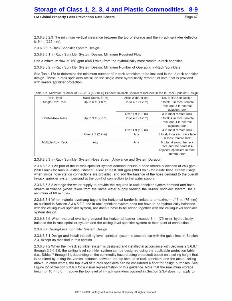
2.3.6.8.5.2.3 The minimum vertical clearance between the top of storage and the in-rack sprinkler deflectoris 9 in. (225 mm).
2.3.6.8.6 In-Rack Sprinkler System Design
2.3.6.8.6.1 In-Rack Sprinkler System Design: Minimum Required Flow
Use a minimum flow of 160 gpm (605 L/min) from the hydraulically most remote in-rack sprinkler.
2.3.6.8.6.2 In-Rack Sprinkler System Design: Minimum Number of Operating In-Rack Sprinklers
See Table 17a to determine the minimum number of in-rack sprinklers to be included in the in-rack sprinklerdesign. These in-rack sprinklers are all on the single most hydraulically remote tier level that is providedwith in-rack sprinkler protection.
Table 17a. Minimum Number of K25.2EC (K360EC) Pendent In-Rack Sprinklers Included in the In-Rack Sprinkler Design
Rack Type Rack Depth, ft (m) Aisle Width, ft (m) No. of IRAS in DesignSingle-Row Rack Up to 6 ft (1.8 m) Up to 4 ft (1.2 m) 6 total; 3 in most remote
rack and 3 in nearestadjacent rack
Over 4 ft (1.2 m) 3 in most remote rackDouble-Row Rack Up to 9 ft (2.7 m) Up to 4 ft (1.2 m) 8 total; 4 in most remote
rack and 4 in nearestadjacent rack
Over 4 ft (1.2 m) 4 in most remote rackOver 9 ft (2.7 m) Any 8 total; 4 on each rack face
in most remote rackMultiple-Row Rack Any Any 8 total; 4 along the rack
face and the nearest 4adjacent sprinklers in most
remote rack
2.3.6.8.6.3 In-Rack Sprinkler System Hose Stream Allowance and System Duration
2.3.6.8.6.3.1 As part of the in-rack sprinkler system demand include a hose stream allowance of 250 gpm(950 L/min) for manual extinguishment. Allow at least 100 gpm (380 L/min) for inside hose stream usage,when inside hose station connections are provided, and add the balance of the hose demand to the overallin-rack sprinkler system demand at the point of connection to the water supply.
2.3.6.8.6.3.2 Arrange the water supply to provide the required in-rack sprinkler system demand and hosestream allowance (when taken from the same water supply feeding the in-rack sprinkler system) for aminimum of 60 minutes.
2.3.6.8.6.4 When material overhang beyond the horizontal barrier is limited to a maximum of 3 in. (75 mm)as outlined in Section 2.3.6.8.2.2, the in-rack sprinkler system does not have to be hydraulically balancedwith the ceiling-level sprinkler system, nor does it have to be added together with the ceiling-level sprinklersystem design.
2.3.6.8.6.5 When material overhang beyond the horizontal barrier exceeds 3 in. (75 mm), hydraulicallybalance the in-rack sprinkler system and the ceiling-level sprinkler system at their point of connection.
2.3.6.8.7 Ceiling-Level Sprinkler System Design
2.3.6.8.7.1 Design and install the ceiling-level sprinkler system in accordance with the guidelines in Section2.3, except as modified in this section.
2.3.6.8.7.2 When the in-rack sprinkler system is designed and installed in accordance with Sections 2.3.6.8.1through 2.3.6.8.6, the ceiling-level sprinkler system can be designed using the applicable protection table(i.e., Tables 7 through 11, depending on the commodity hazard being protected) based on a ceiling height thatis obtained by taking the vertical distance between the top level of in-rack sprinklers and the actual ceilingabove. In other words, the top level of in-rack sprinklers can be considered a floor for design purposes. SeeFigure 22 of Section 2.3.6.6 for a visual representation of this guidance. Note that the maximum storageheight of 10 ft (3.0 m) above the top level of in-rack sprinklers outlined in Section 2.3.4 does not apply to
Storage of Class 1, 2, 3, 4 and Plastic Commodities 8-9FM Global Property Loss Prevention Data Sheets Page 67
©2010-2019 Factory Mutual Insurance Company. All rights reserved.
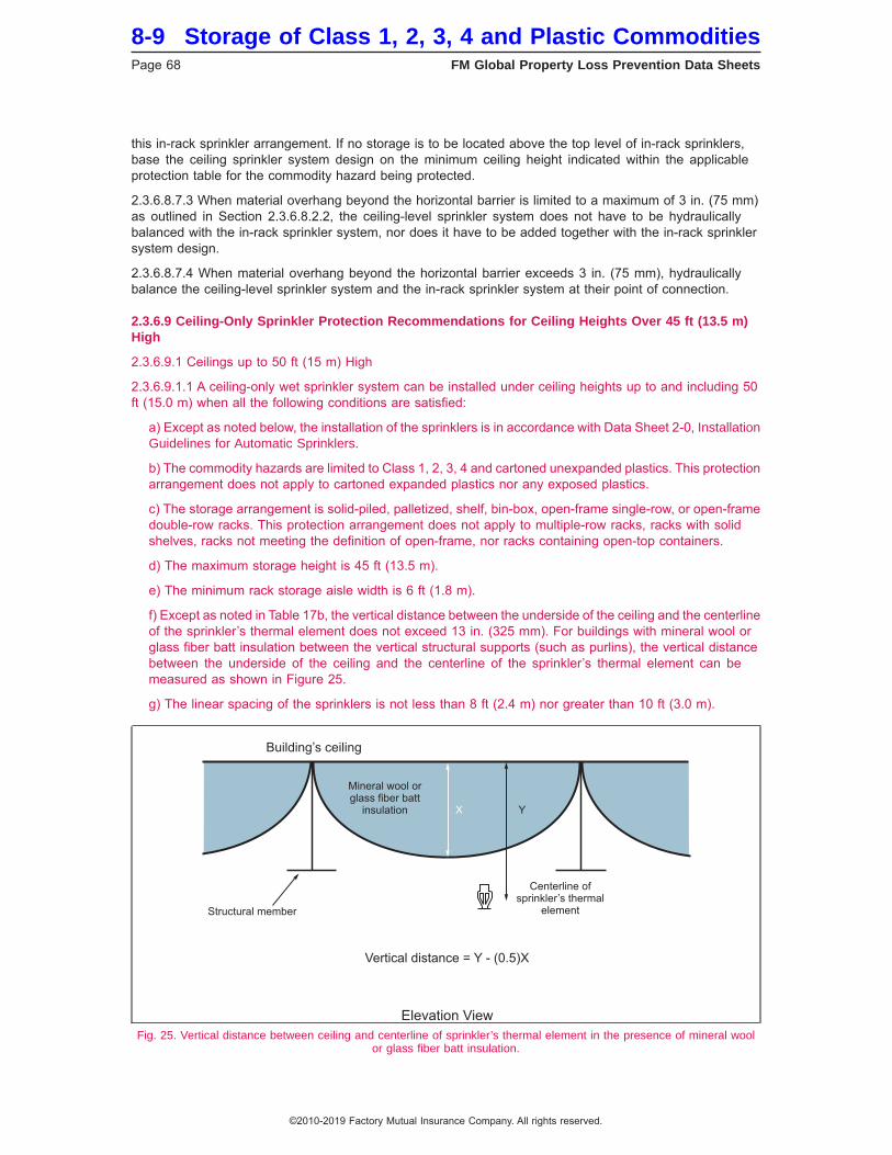
this in-rack sprinkler arrangement. If no storage is to be located above the top level of in-rack sprinklers,base the ceiling sprinkler system design on the minimum ceiling height indicated within the applicableprotection table for the commodity hazard being protected.
2.3.6.8.7.3 When material overhang beyond the horizontal barrier is limited to a maximum of 3 in. (75 mm)as outlined in Section 2.3.6.8.2.2, the ceiling-level sprinkler system does not have to be hydraulicallybalanced with the in-rack sprinkler system, nor does it have to be added together with the in-rack sprinklersystem design.
2.3.6.8.7.4 When material overhang beyond the horizontal barrier exceeds 3 in. (75 mm), hydraulicallybalance the ceiling-level sprinkler system and the in-rack sprinkler system at their point of connection.
2.3.6.9 Ceiling-Only Sprinkler Protection Recommendations for Ceiling Heights Over 45 ft (13.5 m)High
2.3.6.9.1 Ceilings up to 50 ft (15 m) High
2.3.6.9.1.1 A ceiling-only wet sprinkler system can be installed under ceiling heights up to and including 50ft (15.0 m) when all the following conditions are satisfied:
a) Except as noted below, the installation of the sprinklers is in accordance with Data Sheet 2-0, InstallationGuidelines for Automatic Sprinklers.
b) The commodity hazards are limited to Class 1, 2, 3, 4 and cartoned unexpanded plastics. This protectionarrangement does not apply to cartoned expanded plastics nor any exposed plastics.
c) The storage arrangement is solid-piled, palletized, shelf, bin-box, open-frame single-row, or open-framedouble-row racks. This protection arrangement does not apply to multiple-row racks, racks with solidshelves, racks not meeting the definition of open-frame, nor racks containing open-top containers.
d) The maximum storage height is 45 ft (13.5 m).
e) The minimum rack storage aisle width is 6 ft (1.8 m).
f) Except as noted in Table 17b, the vertical distance between the underside of the ceiling and the centerlineof the sprinkler’s thermal element does not exceed 13 in. (325 mm). For buildings with mineral wool orglass fiber batt insulation between the vertical structural supports (such as purlins), the vertical distancebetween the underside of the ceiling and the centerline of the sprinkler’s thermal element can bemeasured as shown in Figure 25.
g) The linear spacing of the sprinklers is not less than 8 ft (2.4 m) nor greater than 10 ft (3.0 m).
Fig. 25. Vertical distance between ceiling and centerline of sprinkler’s thermal element in the presence of mineral woolor glass fiber batt insulation.
8-9 Storage of Class 1, 2, 3, 4 and Plastic CommoditiesPage 68 FM Global Property Loss Prevention Data Sheets
©2010-2019 Factory Mutual Insurance Company. All rights reserved.
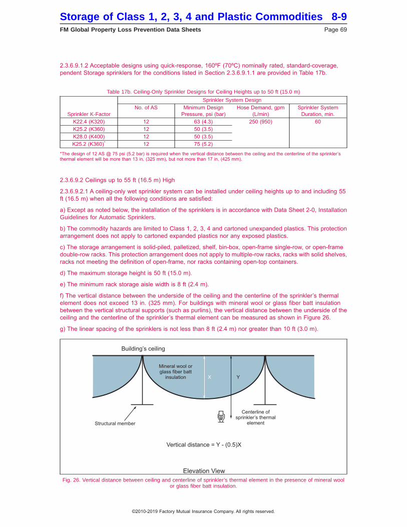
2.3.6.9.1.2 Acceptable designs using quick-response, 160ºF (70ºC) nominally rated, standard-coverage,pendent Storage sprinklers for the conditions listed in Section 2.3.6.9.1.1 are provided in Table 17b.
Table 17b. Ceiling-Only Sprinkler Designs for Ceiling Heights up to 50 ft (15.0 m)
Sprinkler K-Factor
Sprinkler System DesignNo. of AS Minimum Design
Pressure, psi (bar)Hose Demand, gpm
(L/min)Sprinkler System
Duration, min.K22.4 (K320) 12 63 (4.3) 250 (950) 60K25.2 (K360) 12 50 (3.5)K28.0 (K400) 12 50 (3.5)K25.2 (K360)* 12 75 (5.2)
*The design of 12 AS @ 75 psi (5.2 bar) is required when the vertical distance between the ceiling and the centerline of the sprinkler’sthermal element will be more than 13 in. (325 mm), but not more than 17 in. (425 mm).
2.3.6.9.2 Ceilings up to 55 ft (16.5 m) High
2.3.6.9.2.1 A ceiling-only wet sprinkler system can be installed under ceiling heights up to and including 55ft (16.5 m) when all the following conditions are satisfied:
a) Except as noted below, the installation of the sprinklers is in accordance with Data Sheet 2-0, InstallationGuidelines for Automatic Sprinklers.
b) The commodity hazards are limited to Class 1, 2, 3, 4 and cartoned unexpanded plastics. This protectionarrangement does not apply to cartoned expanded plastics nor any exposed plastics.
c) The storage arrangement is solid-piled, palletized, shelf, bin-box, open-frame single-row, or open-framedouble-row racks. This protection arrangement does not apply to multiple-row racks, racks with solid shelves,racks not meeting the definition of open-frame, nor racks containing open-top containers.
d) The maximum storage height is 50 ft (15.0 m).
e) The minimum rack storage aisle width is 8 ft (2.4 m).
f) The vertical distance between the underside of the ceiling and the centerline of the sprinkler’s thermalelement does not exceed 13 in. (325 mm). For buildings with mineral wool or glass fiber batt insulationbetween the vertical structural supports (such as purlins), the vertical distance between the underside of theceiling and the centerline of the sprinkler’s thermal element can be measured as shown in Figure 26.
g) The linear spacing of the sprinklers is not less than 8 ft (2.4 m) nor greater than 10 ft (3.0 m).
Fig. 26. Vertical distance between ceiling and centerline of sprinkler’s thermal element in the presence of mineral woolor glass fiber batt insulation.
Storage of Class 1, 2, 3, 4 and Plastic Commodities 8-9FM Global Property Loss Prevention Data Sheets Page 69
©2010-2019 Factory Mutual Insurance Company. All rights reserved.
2.3.6.9.2.2 The acceptable design for this arrangement is based on standard-coverage, quick-response,160ºF (70ºC) nominally rated K28.0 (K400) pendent Storage sprinklers providing a minimum pressure of 80psi (5.5 bar) from the most remote 9 sprinklers (3 sprinklers on the most remote 3 branch lines) accountingfor a 250 gpm (950 L/min) hose stream allowance and a system duration of 60 minutes.
3.0 SUPPORT FOR RECOMMENDATIONS
3.1 General
The fire protection recommendations in this data sheet are based on testing, loss experience, and engineeringjudgment. Not every situation has been tested, nor has every potential solution been identified. Carefullyconsider all the variables involved when exploring options that differ from those recommended in this datasheet.
3.2 Loss History
Loss experience has shown that when there are no major automatic sprinkler system deficiencies, fires instorage occupancies are controlled by the existing sprinkler system protection arrangement. Major protectiondeficiencies include inadequate water supplies, closed or partially closed valves, obstructed sprinkler piping,missing sprinklers, and flammable liquid or aerosol protection deficiencies. Protection deficiencies wereidentified in all storage losses where the fire was uncontrolled.
Note that storage loss experience to date has involved primarily standard-response K5.6 (K80) or K8.0 (K115)sprinklers. Experience with K11.2 (K160) and larger sprinklers is limited due to their relatively recentdevelopment.
Some general deductions can be made from a study of rack storage losses (solid-piled/palletized losseshave not been studied in similar detail) that occurred in a recent 18-year period, and in which no protectiondeficiencies were identified. These losses involve standard-response K5.6 (K80) and K8.0 (K115) sprinklersexclusively. The basic findings are as follows:
1. In-rack sprinklers, used in conjunction with ceiling-level sprinklers, are overwhelmingly successful.
2. Both the amount of damage and the number of sprinklers that open during a fire increase with higherstorage / building heights.
The percentage of rack storage fires controlled by a given number of sprinklers is shown in the Table 18:
Table 18. Relationship Between the Number of Sprinklers that Operate During a Storage Fire and Fire Control
Number of Sprinklers that Operate During a Fire Percentage of Fires Controlled1 14%
2 or fewer 32%3 or fewer 41%4 or fewer 49%5 or fewer 54%10 or fewer 77%25 or fewer 98%
For sprinkler systems consisting of ceiling-level sprinklers only, the average number of sprinklers that openedduring a storage fire was eight. For sprinkler systems consisting of the combination of ceiling-level and in-racksprinklers, the average number of sprinklers that opened during a storage fire was three ceiling-levelsprinklers and three in-rack sprinklers.
The use of hoses use was identified in 87% of the incidents that operated ten or fewer sprinklers and, whenhoses were used, they were applied either before sprinklers operated or before fire control was achievedin a little more than 50% of the cases. This strong correlation suggests early application of hose streams hasa significant effect on the average number of sprinklers that operate in rack storage fires (it would followthat this is also true for solid-piled / palletized storage fires), and that provision of small hose stations is akey element in the overall protection scheme. It is impossible to say how many catastrophic fires may havebeen prevented by early intervention using hoses.
8-9 Storage of Class 1, 2, 3, 4 and Plastic CommoditiesPage 70 FM Global Property Loss Prevention Data Sheets
©2010-2019 Factory Mutual Insurance Company. All rights reserved.
3.3 Illustrative Losses
3.3.1 Roll Cloth in Racks Obstruct Flue Spaces, Resulting in Extensive Fire and Water Damage
At a large textile facility, 8 to 9 ft (2.4 to 2.7 m) long, encapsulated, finished roll cloth was stored in open-framedouble-row racks up to 12 ft (3.7 m) high on the third floor of a warehouse.
The rolls were only one high per tier, and were packed tightly due to high production demands. This abutmentof the rolls obstructed water from penetrating into the racks and only left about a 1 in. (25 mm) flue at mostof the 10 ft (3.0 m) uprights. A fire started on the bottom tier and traveled down the length of the rack for30 ft (9.0 m) in each direction before the sprinkler system achieved enough penetration to gain control of thefire. During the fire, 91 sprinklers operated, but the facility had a strong water supply with an unlimited watersource. Approximately 200 rolls of cloth were damaged by fire, and all other rolls of cloth and finished goodsin the area were damaged by smoke and water to various degrees. There was extensive water damage tofinished goods stored in a basement area in an adjoining building with wooden intermediate floors.
3.3.2 Many Loss Prevention Principles Compromised in Warehouse Fire
Temporary aisle storage of palletized plastic automobile consoles, portable racked steel core steering wheelswith polyurethane foam padding and PVC skin, and palletized motor oil were introduced into an automotiveparts and accessories warehouse. In most areas of the warehouse, portable racks were stacked six highto a total height of about 20 ft (6.0 m). Permanent racks were 10 ft (3.0 m) high and usually had another 10ft (3.0 m) of baskets stacked on top. The ceiling-level sprinkler system was only capable of protecting thesecommodities in the indicated storage arrangements to a maximum height of 5 ft (1.5 m) based on theavailable water supply.
A fire, probably caused by smoking, resulted in the largest loss FM Global had investigated up to that time.The storage was too high, the sprinkler water application was too low, sprinkler orifice sizes and temperatureratings were incorrect, temporary storage blocked the aisles, and there were no flue spaces.
3.3.3 Inadequate Sprinkler Protection Unable to Control Fire Involving Aisle Storage and Rackswith Solid Shelves
Clothing and shoes were stored in single-row racks from 22 to 26 ft (6.6 to 7.9 m) high. Idle pallets up to12 ft (3.7 m) high were stored in 6 ft (1.8 m) wide aisles between racks. Solid shelves were present in thelower two tiers to form picking bins. In-rack sprinklers were not provided. A fire starting in this area overtaxedthe ceiling-level sprinkler system. Roof collapse occurred within 20 minutes of fire discovery. Approximately200,000 ft2 (18,500 m2) of this building was destroyed.
3.3.4 Fire in High Rack-Storage Controlled by In-Rack Sprinklers
Fire in clothing stored in cartons on 16-tier, 39 ft (11.9 m) high racks was well controlled by four in-racksprinklers and one ceiling-level sprinkler. In-rack sprinklers were provided at four levels. Completeextinguishment was provided via two small hoses.
3.3.5 Lack of In-Rack Sprinklers for Racks With Solid Shelves Results in Extensive Fire Damage
Upholstered furniture was stored on cantilever racks to 15 ft (4.5 m) high. Racks were 8 ft (2.4 m) deep andequipped with 56 ft2 (5.2 m2) solid plywood shelves. In-rack sprinklers were not provided. A fire starting inthe rack storage quickly overtaxed ceiling-level sprinklers, with initial roof collapse occurring within 20 minutesof fire discovery. Approximately half of the 202 by 405 ft (60 by 120 m) building’s roof collapsed and storageburned. Roof collapse remote from the point of fire origin apparently hindered further horizontal fire spreadby blocking flames from reaching uninvolved areas.
3.3.6 Open-Top Containers in Racks Interfere with Sprinkler Water Penetration Resulting inUncontrolled Fire
Synthetic fiber socks were stored in open-top cardboard ‘‘tote boxes’’ in racks 16 ft (4.8 m) high. There wereeight levels of boxes supported on metal angles in each rack. A fire started in or near the racks and waterfrom ceiling-level sprinklers collected in boxes on the top tier levels, preventing adequate sprinkler water frompenetrating through the racks to control the fire. A 390 by 530 ft (120 by 160 m) portion of the facility wasdestroyed. In-rack sprinklers were provided when the facility was rebuilt.
Storage of Class 1, 2, 3, 4 and Plastic Commodities 8-9FM Global Property Loss Prevention Data Sheets Page 71
©2010-2019 Factory Mutual Insurance Company. All rights reserved.

3.3.7 Poor Housekeeping Leads to Excessive Fire Spread
Solid-pile storage of 10 ft (3.0 m) high rolled and baled synthetic greige goods in burlap wrapping (a ClassIV commodity) was located in a one-story, 6800 ft2 (630 m2) section of a warehouse. There was 4 ft (1.2m) clearance to ceiling sprinklers. Protection was by a dry-pipe sprinkler system with 100 ft2 (9.0 m2) spacingusing K5.6 (K80), 160°F (70°F) nominally rated ceiling-level sprinklers. The system was supplied by publicwater and a manually started fire pump rated at 1000 gpm (3800 L/min) at 100 psi (6.9 bar), capable ofdelivering a minimum pressure of 8 psi (0.6 bar) to the most remote 30 sprinklers, without supplying milluse or hose streams.
The plant engineer noted a rapidly spreading fire in lint accumulations in the corner of the warehouse neara baling machine. The emergency response team (ERT) and public fire service responded within tenminutes. The fire was controlled by 68 operating sprinklers and extinguished within one hour when ceiling-levelsprinklers were supplemented by one large and three small hose streams. Approximately 150 bales and200 rolls of greige goods were wet by the sprinkler system. Wood building walls and roof were scorched andcharred.
Weak water supplies (water supplies to sprinklers were depleted by mill use and hose streams) and lintaccumulations combined to permit excessive fire development. The manual fire pump was not started forfear of contaminating mill-use water supplies.
3.3.8 Strong Water Supply Overcomes Plugged Sprinklers
Palletized storage of 12 ft (3.7 m) high, cartoned paperboard flats (a Class 3 commodity) with 4 ft (1.2 m)clearance to ceiling-level sprinklers was in a one-story warehouse. Protection was provided by a dry-pipesprinkler system with 64 ft2 (6.0 m2) spacing with K5.6 (K80), 280°F (140°C) nominally rated ceiling-levelsprinklers. The system was supplied by an automatic fire pump rated at 1500 gpm (5700 L/min) at 100 psi(6.9 bar) and capable of providing a minimum pressure of 93 psi (6.4 bar) over the most remote 38 sprinklerson 64 ft2 (6.0 m2) spacing.
The public fire service was notified of the storage fire 30 minutes after the alarm and achieved extinguishmentwithin one hour, using three small hoses. A total of 20 ceiling-level sprinklers opened and controlled limitingthe damage to 30 pallet loads of cartoned paperboard flats and 250 ft2 (23 m2) of charred ceiling.
An investigation of the 20 sprinklers that opened during the fire indicated that 10 of them were plugged withstones. The remaining 10 operating sprinklers were able to limit the fire spread in large part because theexisting water supplies were able to provide well in excess of the normal recommended water application forthe array and product.
4.0 REFERENCES
4.1 FM Global
Data Sheet 1-2, EarthquakesData Sheet 1-10, Smoke and Heat Venting in One-story Sprinklered BuildingsData Sheet 1-12, Ceilings and Concealed SpacesData Sheet 1-24, Protection Against Liquid DamageData Sheet 2-0, Installation Guidelines for Automatic SprinklersData Sheet 2-8, Earthquake Protection for Water-Based Fire Protection SystemsData Sheet 5-48 Automatic Fire DetectionData Sheet 7-29, Ignitable Liquid Storage in Portable ContainersData Sheet 8-1, Commodity ClassificationData Sheet 8-24, Idle Pallet StorageData Sheet 8-29, Refrigerated Storage
APPENDIX A GLOSSARY OF TERMS
Aisle: An aisle is a clear space of greater than 2 ft (0.6 m) normally maintained between commodities storedeither in racks or on the floor. The aisle allows for the transfer of commodities to or from the rack or the on-floorstorage area.
Approval Guide: An online resource of FM Approvals that provides a guide to equipment, materials, andservices that have been FM Approved for property conservation.
8-9 Storage of Class 1, 2, 3, 4 and Plastic CommoditiesPage 72 FM Global Property Loss Prevention Data Sheets
©2010-2019 Factory Mutual Insurance Company. All rights reserved.
Bin-Box Storage: A storage arrangement that typically consists of solid shelves vertically located no morethan 3 ft (0.9 m) apart in combination with solid full-height wooden or metal vertical barriers that arehorizontally located no more than 4 ft (1.2 m) apart. There is usually a solid backing for each bin-box storageunit, but this is not always the case. While this type of storage arrangement typically shields direct waterapplication to the burning commodity maintained within each bin-box storage unit, the relatively low tier heightbetween solid shelves coupled with the full-height vertical barriers help to reduce the heat release rate ofthe fire as well as severely delay its potential for horizontal fire growth.
Clearance: The clear space maintained between the top of storage and the deflector of the sprinkler (ceilingor in-rack) located above it. For all ceiling-level sprinklers, a minimum clearance of 3 ft (0.9 m) is required.For all in-rack sprinklers installed in an IRAS(EO) arrangement, the deflector must be located a minimum of6 in. (150 mm) above the top of storage.
Commodity: A commodity is the combination of product, packaging material, container, and material handlingaids (e.g., pallets). Data Sheet 8-1, Commodity Classification, contains commodity classification guidelinesthat are applicable to this data sheet. The purpose of assigning a commodity classification is to allowspecification of the proper level of fire protection. A commodity classification is dependent on how the productburns and how the burning product responds to the application of sprinkler discharge. Protection specificationsin this data sheet are based on the following categories of commodity:
• Class 1, Class 2, and Class 3 commodity hazards
• Class 4 commodity hazards and Cartoned Unexpanded Plastics
• Uncartoned Unexpanded Plastics
• Cartoned Expanded Plastics
• Uncartoned Expanded Plastics
Duration or System Duration: Water supply system duration is a defined time period between when a fireinitially activates a sprinkler system and when the fire is extinguished. Fire extinguishment usually isaccomplished by the manual firefighting efforts of public fire service personnel, facility fire service personnel,or facility emergency response team personnel applying hose streams directly onto the surfaces of theburning commodity. Duration takes into consideration the commodity hazard’s expected fire size in thepresence of the system’s specific sprinklers, as well as manual fire extinguishment by either one or two appliedhose streams.
Encapsulation: A method of packaging consisting of a plastic sheet completely enclosing the sides andtop of a pallet load containing a combustible commodity or a group of combustible commodities or combustiblepackages. Totally noncombustible commodities on wood pallets enclosed only by a plastic sheet as describedabove are not considered to be encapsulated. The term ‘‘encapsulation’’ also applies to individual cartonsthat are enclosed on the top and sides in plastic, and to cartons waterproofed by coatings on the exteriorsurfaces.
The term ‘‘encapsulation’’ does not apply to individual plastic enclosed items inside a larger non-plasticenclosed or non-waterproofed container. If holes or voids in the plastic or waterproof cover on the top of thecarton exceed more than half the area of the top, the term ‘‘encapsulation’’ does not apply.
The protection design guidelines provided in this data sheet account for the presence of encapsulation anddo not need to be adjusted.
Fire Protection Scheme 8-9A: A specific fire protection scheme that uses both horizontal barriers andquick-response in-rack sprinklers to protect high-challenge commodities that would otherwise (1) require asignificantly higher ceiling-level design and/or water supply to protect it, or (2) require in-rack sprinklerswhereas a ceiling-only option is available for the other commodity hazards maintained within the storagearea, or (3) require a higher number of in-rack sprinkler tier levels when compared to the number of tier levelsrequired for the other commodity hazards maintained within the storage area.
By segregating the high-challenge commodities into a designated storage rack (or racks) that is equippedwith Fire Protection Scheme 8-9A (i.e., Scheme 8-9A) protection, the sprinkler design for the storage area canthen be based on the requirements for the highest commodity hazard not being protected by Scheme 8-9Aprotection. This protection scheme in essence treats the high-challenge commodities as if they have beenremoved from the storage area.
Storage of Class 1, 2, 3, 4 and Plastic Commodities 8-9FM Global Property Loss Prevention Data Sheets Page 73
©2010-2019 Factory Mutual Insurance Company. All rights reserved.
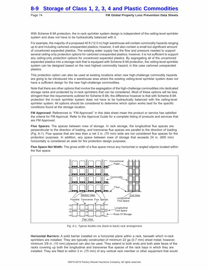
With Scheme 8-9A protection, the in-rack sprinkler system design is independent of the ceiling-level sprinklersystem and does not have to be hydraulically balanced with it.
For example, the majority of a proposed 40 ft (12.0 m) high warehouse will contain commodity hazards rangingup to and including cartoned unexpanded plastics; however, it will also contain a small but significant amountof uncartoned expanded plastics. The existing water supply has the flow and pressure needed to supportseveral ceiling-only protection options for cartoned unexpanded plastics; however, it is not sufficient to supportany ceiling-only protection options for uncartoned expanded plastics. By segregating all of the uncartonedexpanded plastics into a storage rack that is equipped with Scheme 8-9A protection, the ceiling-level sprinklersystem can be designed based on the next highest commodity hazard; in this case cartoned unexpandedplastics.
This protection option can also be used at existing locations when new high-challenge commodity hazardsare going to be introduced into a warehouse area where the existing ceiling-level sprinkler system does nothave a sufficient design for the new high-challenge commodities.
Note that there are other options that involve the segregation of the high-challenge commodities into dedicatedstorage racks and protected by in-rack sprinklers that can be considered. Most of these options will be lessstringent than the requirements outlined for Scheme 8-9A; the difference however is that with Scheme 8-9Aprotection the in-rack sprinkler system does not have to be hydraulically balanced with the ceiling-levelsprinkler system. All options should be considered to determine which option works best for the specificconditions found at the storage location.
FM Approved: References to ‘‘FM Approved’’ in this data sheet mean the product or service has satisfiedthe criteria for FM Approval. Refer to the Approval Guide for a complete listing of products and services thatare FM Approved.
Flue Spaces: The spaces between rows of storage. In rack storage, the longitudinal flue spaces areperpendicular to the direction of loading, and transverse flue spaces are parallel to the direction of loading(Fig. A-1). Flue spaces that are less than a net 3 in. (75 mm) wide are not considered flue spaces for fireprotection purposes. In addition, any space between rows of storage that exceeds 24 in. (600 mm)horizontally is considered an aisle for fire protection design purposes.
Flue Space Net Width: The gross width of a flue space minus any horizontal or angled objects located withinthe flue space.
Horizontal Barriers: A solid barrier installed on a horizontal plane within a rack, beneath which in-racksprinklers are installed. They are typically constructed of minimum 22 ga (0.7 mm) sheet metal; however,minimum 3/8 in. (10 mm) plywood can also be used. They extend to both ends and both aisle faces of theracks covering up both the longitudinal and transverse flue spaces of the rack bays in which they areinstalled. They are fitted to within 3 in. (75 mm) of any vertical rack member or other equipment that would
Fig. A-1. Typical double-row (back-to-back) rack arrangement
8-9 Storage of Class 1, 2, 3, 4 and Plastic CommoditiesPage 74 FM Global Property Loss Prevention Data Sheets
©2010-2019 Factory Mutual Insurance Company. All rights reserved.
create an opening, such as vertical in-rack sprinkler pipe drops. Their purpose is to impede vertical fire spreadby blocking off normally open flue spaces, while also helping to achieve prompt in-rack sprinkler operationby banking heat down to the in-rack sprinklers that must be installed under each barrier.
In-Rack Sprinklers: These sprinklers are typically K5.6 (K80), K8.0 (K115) or K11.2 (K160) Nonstoragesprinklers equipped with an attached water shield over the top of the thermal sensing element. The watershield prevents wetting of the thermal sensing element by water from sprinklers at a higher elevation in therack or at ceiling level. Note that the water shield is not a heat collector and has virtually no effect on howfast the in-rack sprinkler will operate.
In-rack sprinklers are classified as either longitudinal in-rack sprinklers or face in-rack sprinklers. Both typesof sprinklers are meant to be located within the transverse flue spaces of the storage array and positionedso that water can be delivered into the flue spaces they are intended to protect. If in-rack sprinklers are notlocated at every transverse flue space intersection, then the in-rack sprinklers must also be positioned suchthat they can discharge water across the top of any storage at the level the in-rack sprinklers are provided.Longitudinal in-rack sprinklers are located within the longitudinal flue spaces of a double-row or multiple-rowrack, or down the middle of a single-row rack. Face in-rack sprinklers are located within the rack storagearray at transverse flue spaces no more than 18 in. (450 mm) horizontally from the face of the rack. Bothlongitudinal and face in-rack sprinklers need to be positioned within 3 in. (75 mm) horizontally of theirdesignated transverse flue space intersection. When in-rack sprinklers are required per the protectionguidelines, refer to the appropriate in-rack sprinkler figure to determine the proper horizontal location of thein-rack sprinklers.
Longitudinal in-rack sprinklers help prevent horizontal fire spread down the length of the rack. Face in-racksprinklers help prevent horizontal fire spread down the length of the rack as well as provide a water curtainbetween two adjacent racks to hinder fire jump across the aisle.
K-factor: Also known as the discharge coefficient, it is a numerical value representing the orifice size of thesprinkler in combination with the expected flow through the sprinkler orifice at a given pressure value. It iscalculated using the following equation:
K = Q√P
Where: Q is the flow through the sprinkler orifice in gpm (L/min).P is the pressure at the sprinkler orifice in psi (bar).The units for K are gpm/psi0.5 ([L/min]/bar0.5).
See Table 1 for K-factor values of Storage sprinklers that are currently FM Approved.
Movable Racks: Movable racks are on fixed rails or guides. They can be moved in one direction only in ahorizontal two-dimensional plane. A moving aisle is created as abutting racks are loaded or unloaded, thenmoved across the aisle to abut other racks. Movable rack arrangements generally result in the same protectionneeds as those for multiple-row racks.
Nominal Temperature Rating: An indicated temperature rating that represents a given range applicablefor the conditions the sprinkler is to be used for. This data sheet recommends sprinklers having nominaltemperature ratings of 1600F (700C), 2120F (100 0C) or 2800F (1400C). The following indicates the rangesthese nominal temperature ratings represent:
Nominal Temperature Rating, °F (°C) Actual Temperature Range,°F (°C)160 (70) 155 (68) - 165 (74)
212 (100) 200 (93) - 220 (104)280 (140) 280 (138) - 286 (141)
Occupancy-Specific Data Sheet: An FM Global property loss prevention data sheet that addresses a specificoccupancy hazard. Individual data sheets belong to a numbered ″series″ representing the following subjects:
Storage of Class 1, 2, 3, 4 and Plastic Commodities 8-9FM Global Property Loss Prevention Data Sheets Page 75
©2010-2019 Factory Mutual Insurance Company. All rights reserved.
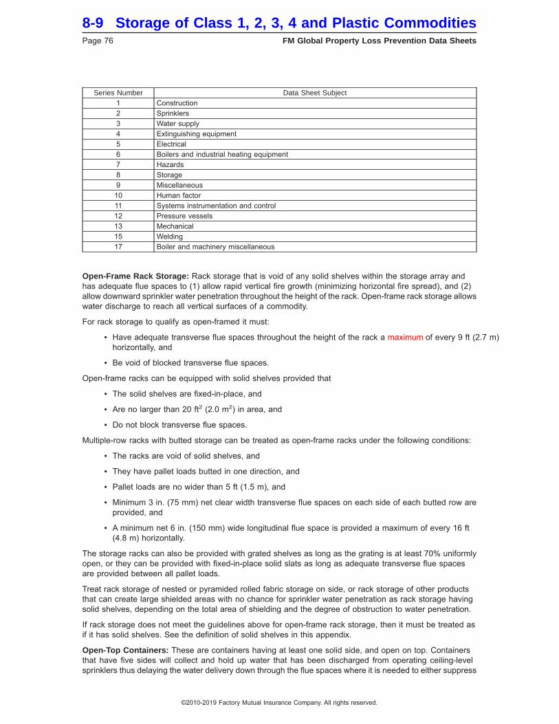
Series Number Data Sheet Subject1 Construction2 Sprinklers3 Water supply4 Extinguishing equipment5 Electrical6 Boilers and industrial heating equipment7 Hazards8 Storage9 Miscellaneous10 Human factor11 Systems instrumentation and control12 Pressure vessels13 Mechanical15 Welding17 Boiler and machinery miscellaneous
Open-Frame Rack Storage: Rack storage that is void of any solid shelves within the storage array andhas adequate flue spaces to (1) allow rapid vertical fire growth (minimizing horizontal fire spread), and (2)allow downward sprinkler water penetration throughout the height of the rack. Open-frame rack storage allowswater discharge to reach all vertical surfaces of a commodity.
For rack storage to qualify as open-framed it must:
• Have adequate transverse flue spaces throughout the height of the rack a maximum of every 9 ft (2.7 m)horizontally, and
• Be void of blocked transverse flue spaces.
Open-frame racks can be equipped with solid shelves provided that
• The solid shelves are fixed-in-place, and
• Are no larger than 20 ft2 (2.0 m2) in area, and
• Do not block transverse flue spaces.
Multiple-row racks with butted storage can be treated as open-frame racks under the following conditions:
• The racks are void of solid shelves, and
• They have pallet loads butted in one direction, and
• Pallet loads are no wider than 5 ft (1.5 m), and
• Minimum 3 in. (75 mm) net clear width transverse flue spaces on each side of each butted row areprovided, and
• A minimum net 6 in. (150 mm) wide longitudinal flue space is provided a maximum of every 16 ft(4.8 m) horizontally.
The storage racks can also be provided with grated shelves as long as the grating is at least 70% uniformlyopen, or they can be provided with fixed-in-place solid slats as long as adequate transverse flue spacesare provided between all pallet loads.
Treat rack storage of nested or pyramided rolled fabric storage on side, or rack storage of other productsthat can create large shielded areas with no chance for sprinkler water penetration as rack storage havingsolid shelves, depending on the total area of shielding and the degree of obstruction to water penetration.
If rack storage does not meet the guidelines above for open-frame rack storage, then it must be treated asif it has solid shelves. See the definition of solid shelves in this appendix.
Open-Top Containers: These are containers having at least one solid side, and open on top. Containersthat have five sides will collect and hold up water that has been discharged from operating ceiling-levelsprinklers thus delaying the water delivery down through the flue spaces where it is needed to either suppress
8-9 Storage of Class 1, 2, 3, 4 and Plastic CommoditiesPage 76 FM Global Property Loss Prevention Data Sheets
©2010-2019 Factory Mutual Insurance Company. All rights reserved.
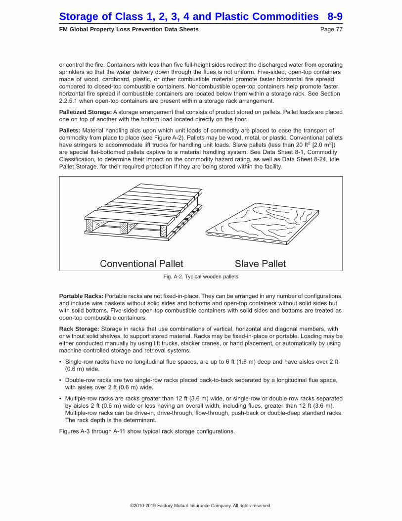
or control the fire. Containers with less than five full-height sides redirect the discharged water from operatingsprinklers so that the water delivery down through the flues is not uniform. Five-sided, open-top containersmade of wood, cardboard, plastic, or other combustible material promote faster horizontal fire spreadcompared to closed-top combustible containers. Noncombustible open-top containers help promote fasterhorizontal fire spread if combustible containers are located below them within a storage rack. See Section2.2.5.1 when open-top containers are present within a storage rack arrangement.
Palletized Storage: A storage arrangement that consists of product stored on pallets. Pallet loads are placedone on top of another with the bottom load located directly on the floor.
Pallets: Material handling aids upon which unit loads of commodity are placed to ease the transport ofcommodity from place to place (see Figure A-2). Pallets may be wood, metal, or plastic. Conventional palletshave stringers to accommodate lift trucks for handling unit loads. Slave pallets (less than 20 ft2 [2.0 m2])are special flat-bottomed pallets captive to a material handling system. See Data Sheet 8-1, CommodityClassification, to determine their impact on the commodity hazard rating, as well as Data Sheet 8-24, IdlePallet Storage, for their required protection if they are being stored within the facility.
Portable Racks: Portable racks are not fixed-in-place. They can be arranged in any number of configurations,and include wire baskets without solid sides and bottoms and open-top containers without solid sides butwith solid bottoms. Five-sided open-top combustible containers with solid sides and bottoms are treated asopen-top combustible containers.
Rack Storage: Storage in racks that use combinations of vertical, horizontal and diagonal members, withor without solid shelves, to support stored material. Racks may be fixed-in-place or portable. Loading may beeither conducted manually by using lift trucks, stacker cranes, or hand placement, or automatically by usingmachine-controlled storage and retrieval systems.
• Single-row racks have no longitudinal flue spaces, are up to 6 ft (1.8 m) deep and have aisles over 2 ft(0.6 m) wide.
• Double-row racks are two single-row racks placed back-to-back separated by a longitudinal flue space,with aisles over 2 ft (0.6 m) wide.
• Multiple-row racks are racks greater than 12 ft (3.6 m) wide, or single-row or double-row racks separatedby aisles 2 ft (0.6 m) wide or less having an overall width, including flues, greater than 12 ft (3.6 m).Multiple-row racks can be drive-in, drive-through, flow-through, push-back or double-deep standard racks.The rack depth is the determinant.
Figures A-3 through A-11 show typical rack storage configurations.
Fig. A-2. Typical wooden pallets
Storage of Class 1, 2, 3, 4 and Plastic Commodities 8-9FM Global Property Loss Prevention Data Sheets Page 77
©2010-2019 Factory Mutual Insurance Company. All rights reserved.
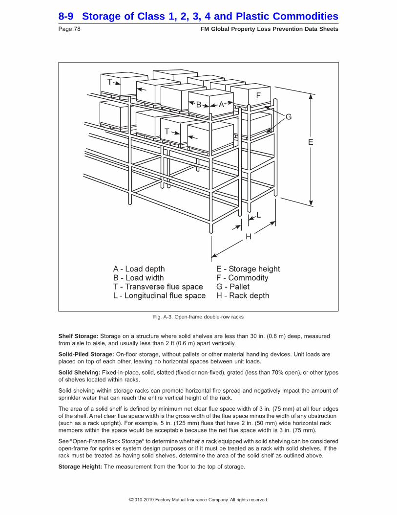
Shelf Storage: Storage on a structure where solid shelves are less than 30 in. (0.8 m) deep, measuredfrom aisle to aisle, and usually less than 2 ft (0.6 m) apart vertically.
Solid-Piled Storage: On-floor storage, without pallets or other material handling devices. Unit loads areplaced on top of each other, leaving no horizontal spaces between unit loads.
Solid Shelving: Fixed-in-place, solid, slatted (fixed or non-fixed), grated (less than 70% open), or other typesof shelves located within racks.
Solid shelving within storage racks can promote horizontal fire spread and negatively impact the amount ofsprinkler water that can reach the entire vertical height of the rack.
The area of a solid shelf is defined by minimum net clear flue space width of 3 in. (75 mm) at all four edgesof the shelf. A net clear flue space width is the gross width of the flue space minus the width of any obstruction(such as a rack upright). For example, 5 in. (125 mm) flues that have 2 in. (50 mm) wide horizontal rackmembers within the space would be acceptable because the net flue space width is 3 in. (75 mm).
See ″Open-Frame Rack Storage″ to determine whether a rack equipped with solid shelving can be consideredopen-frame for sprinkler system design purposes or if it must be treated as a rack with solid shelves. If therack must be treated as having solid shelves, determine the area of the solid shelf as outlined above.
Storage Height: The measurement from the floor to the top of storage.
Fig. A-3. Open-frame double-row racks
8-9 Storage of Class 1, 2, 3, 4 and Plastic CommoditiesPage 78 FM Global Property Loss Prevention Data Sheets
©2010-2019 Factory Mutual Insurance Company. All rights reserved.
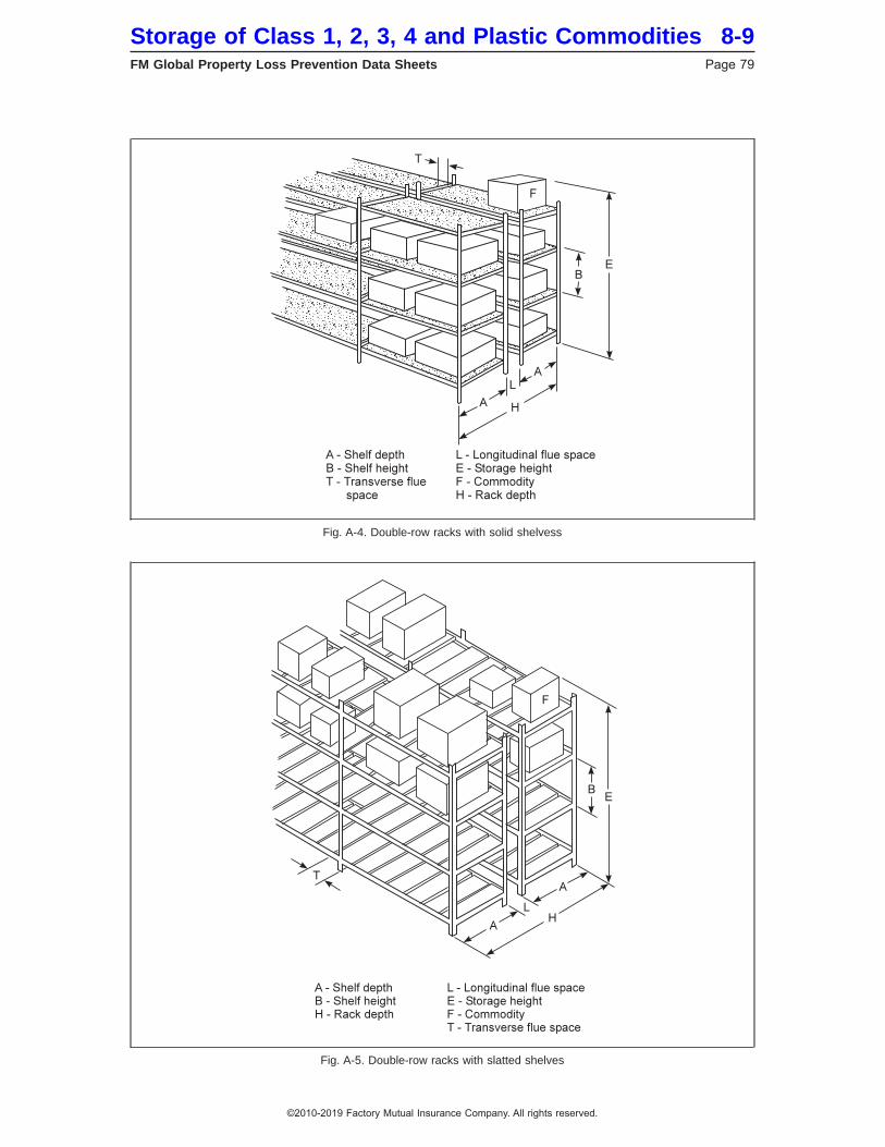
Fig. A-4. Double-row racks with solid shelvess
Fig. A-5. Double-row racks with slatted shelves
Storage of Class 1, 2, 3, 4 and Plastic Commodities 8-9FM Global Property Loss Prevention Data Sheets Page 79
©2010-2019 Factory Mutual Insurance Company. All rights reserved.
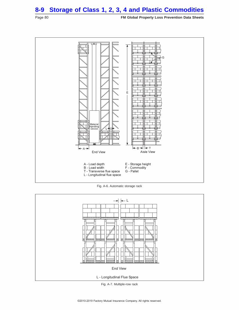
Fig. A-6. Automatic storage rack
Fig. A-7. Multiple-row rack
8-9 Storage of Class 1, 2, 3, 4 and Plastic CommoditiesPage 80 FM Global Property Loss Prevention Data Sheets
©2010-2019 Factory Mutual Insurance Company. All rights reserved.

Fig. A-8. Flow-through pallet rack
Fig. A-9. Drive-in rack, two or more pallets deep
Storage of Class 1, 2, 3, 4 and Plastic Commodities 8-9FM Global Property Loss Prevention Data Sheets Page 81
©2010-2019 Factory Mutual Insurance Company. All rights reserved.
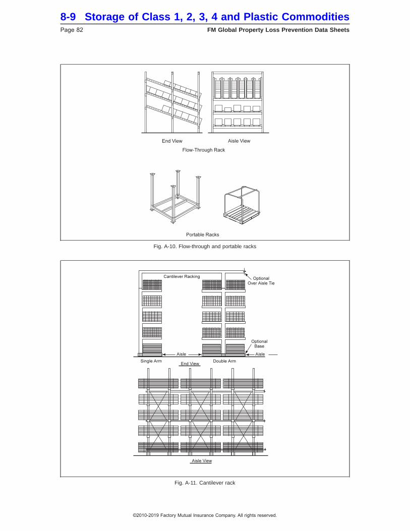
Fig. A-10. Flow-through and portable racks
Fig. A-11. Cantilever rack
8-9 Storage of Class 1, 2, 3, 4 and Plastic CommoditiesPage 82 FM Global Property Loss Prevention Data Sheets
©2010-2019 Factory Mutual Insurance Company. All rights reserved.

Tier: Each vertical segment of storage within a rack. The term “tier” is used only to define the vertical locationfor in-rack sprinklers when storage racks are equipped with solid shelves greater than 64 ft2 (6.0 m2) in area.
Water Delivery Time: The time interval, measured in seconds, of both the trip time and the water traveltime of a sprinkler system. It can also be defined as the time interval, in seconds, between the following twoevents:
(1) The point in time when the most hydraulically remote sprinkler on a dry-pipe, preaction, or similar typeof sprinkler system equipped with an automatic system valve opens.
(2) The point in time when pressure at the most remote sprinkler reaches or surpasses the design pressurefor the sprinkler system.
APPENDIX B DOCUMENT REVISION HISTORY
July 2019. Interim revision. A new Section 2.3.6.9 has been created to address the installation and designguidelines for ceiling-only protection options involving ceiling heights of 50 ft (15 m) and 55 ft (16.5 m).
July 2018. Interim revision. a new Section 2.3.6.8 has been created to address the installation and designguidelines for protection scheme using quick-response K25.2EC (K360EC) pendent sprinklers as in-racksprinklers in combination with horizontal barriers to protect open-frame rack storage of commodity hazardsup to and including cartoned unexpanded plastics when the in-rack sprinkler protection was installed 30 ft (9.0m) above floor level.
January 2018. Interim revision. The following changes were made:
A. Section 2.2.5.1 regarding open-top containers was revised to (1) remove the option where containerscould be mixed within storage if they did not extend into the transverse flue spaces, (2) remove the optionof placing a flat or domed-shaped fixed-in-place lid over the top tier of storage, and (3) clarify the in-racksprinkler arrangement needed in the presence of open-top combustible containers. Due to these changes,Section 2.3.4.6.3.1 was also modified.
B. Section 2.3.6.1 was modified to incorporate all of the ceiling-only protection design guidelines for Class1, 2 and 3 commodities under ceilings that are over 30 ft (9.0 m) protected by dry-pipe and similar sprinklersystems. Both Tables 2 and 7 were modified as part of this revision.
C. Protection guidelines for the newly FM Approved standard-response, standard-coverage, 280°F (140°C)nominally rated K33.6 (K480) upright sprinkler were incorporated into Section 2.3.6.1.
D. Figures 10 through 14 were modified to clarify where in-rack sprinklers are needed horizontally within astorage rack structure.
E. The footnotes in Tables 4, 6, 9, and 11 regarding the Tyco TY9226 sprinkler have been removed.
F. The guidelines in Table 6 for the quick-response, upright K14.0 (K200) and K16.8 (K240) sprinklers wererevised.
June 2015. Interim revision. The following changes were made:
• Added a new section (2.3.6.6) on in-rack sprinkler protection based on recent testing
• Added a new section (2.3.6.7) on a potential in-rack sprinkler retrofit protection option for uncartonedunexpanded plastics stored in open-frame double-row racks
• Incorporated Engineering Bulletins 06-11 and 07-12
• Modified the designs for K11.2 (K160) and standard-response K16.8 (K240) upright sprinklers so thepressure values represent the values that were tested
• Modified Tables 2, 3, 7 and 8 based on recent testing of the quick-response K22.4 (K320) pendent sprinkler
• Modified the dry system designs in Table 5 so they are consistent with Table 10
• Modified the protection options in Tables 5, 6, 10 and 11 for both the quick-response K22.4 (K320) pendentand quick-response K25.2 (K360) pendent sprinklers based on recent testing
• Modified the hose and duration requirements for Scheme 8-9A
• Clarified guidance in Sections 2.3.2.5, 2.3.3.7.2.3 and 2.3.3.7.3.1
Storage of Class 1, 2, 3, 4 and Plastic Commodities 8-9FM Global Property Loss Prevention Data Sheets Page 83
©2010-2019 Factory Mutual Insurance Company. All rights reserved.

January 2011. Clarifications were made in Section 2.3.3.7.2, Ceiling-Level Design Guidelines.
September 2010. This data sheet has been revised to incorporate the following changes:
• The footnote regarding the Tyco TY9226 sprinkler was inadvertently left out of the March 2010 versionof Data Sheet 8-9. It has been added back into this data sheet and is found at the bottom of Tables 4,6, 9 and 11.
• Table 1 was modified to show a reduced linear and area spacing for K25.2EC (K360EC) sprinklers whenthe ceiling height exceeds 30 ft (9.0 m) and the protection is based on ceiling-only designs
• The ceiling-level design for the K25.2EC (K360EC) pendent quick-response sprinkler for ceiling heightsup to 35 ft (10.5 m) was modified in Tables 2, 3, 7 and 8 from 6 sprinklers to 8 sprinklers.
• The ceiling-level design for the K25.2 (K360) pendent standard-response sprinkler for ceiling heights of25 ft (7.5 m) and 30 ft (9.0 m) was modified in Table 8 from a pressure of 15 psi (1.0 bar) to 10 psi(0.7 bar).
• The ceiling-level designs for the K25.2EC (K360EC) pendent and upright quick-response sprinkler forceiling heights up to 25 ft (7.5 m) were modified in Tables 2, 3, 4, 7, 8 and 9. In addition the ceiling-leveldesign for this sprinkler was also changed in Table 4 for a ceiling height of 30 ft (9.0 m).
March 2010. This data sheet has been revised to incorporate the following changes:
A. The protection tables have been reorganized into five categories based on the following commodities:
1. Class 1, Class 2, and Class 3 commodities2. Class 4 and Cartoned Unexpanded Plastic commodities3. Cartoned Expanded Plastic commodities4. Uncartoned Unexpanded Plastic commodities5. Uncartoned Expanded Plastic commodities
B. The terms “Control Mode Density Area (CMDA) sprinkler,” “Control Mode Specific Application (CMSA)sprinkler,” and “Suppression Mode sprinkler” have been replaced with the term “Storage sprinkler.” This newterminology allows for the following changes:
• Only sprinklers considered acceptable for the protection of the commodities addressed in this data sheet,either at ceiling level or within storage racks, are listed as protection options.
• All ceiling-level sprinkler protection options for a given commodity and storage arrangement are listed ina single protection table.
• All ceiling-level sprinkler protection options are based on a single design format (i.e., number of sprinklers@ minimum operating pressure).
C. The following parameters are no longer considered when determining protection options:
• Storage height
• Aisle width
• Favorable and Non-Favorable factors
D. Section 2.2.5.1 on open-top combustible containers has been modified and now also addresses whenopen-top noncombustible containers need special consideration.
E. The maximum recommended flow for a K5.6 (K80) in-rack sprinkler has been increased to 30 gpm (115L/min).
June 2009. Minor editorial changes were made for this revision.
January 2009. Corrections were made to Table 2.3.7.5(b). Also, corrections were made to the metric demandareas in Table 2.3.7.3(l), CMDA Sprinklers Installed on Dry System for Rack Storage up to 25 ft (7.5 m) ofUncartoned Expanded Plastic Commodities.
May 2008. Figure 2.3.4.2(d) was modified due to an editorial error.
January 2008. Combined the protection guidelines for Class 1 and 2 commodities protected by CMDAsprinklers into a single protection table.
8-9 Storage of Class 1, 2, 3, 4 and Plastic CommoditiesPage 84 FM Global Property Loss Prevention Data Sheets
©2010-2019 Factory Mutual Insurance Company. All rights reserved.
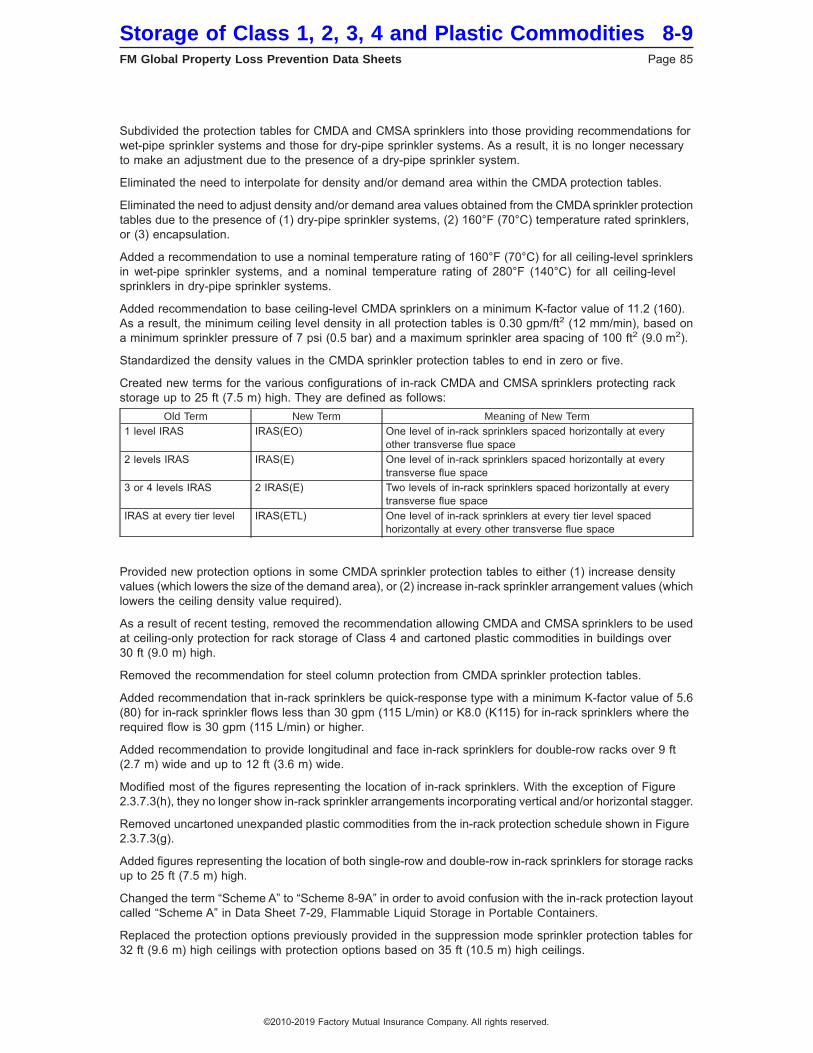
Subdivided the protection tables for CMDA and CMSA sprinklers into those providing recommendations forwet-pipe sprinkler systems and those for dry-pipe sprinkler systems. As a result, it is no longer necessaryto make an adjustment due to the presence of a dry-pipe sprinkler system.
Eliminated the need to interpolate for density and/or demand area within the CMDA protection tables.
Eliminated the need to adjust density and/or demand area values obtained from the CMDA sprinkler protectiontables due to the presence of (1) dry-pipe sprinkler systems, (2) 160°F (70°C) temperature rated sprinklers,or (3) encapsulation.
Added a recommendation to use a nominal temperature rating of 160°F (70°C) for all ceiling-level sprinklersin wet-pipe sprinkler systems, and a nominal temperature rating of 280°F (140°C) for all ceiling-levelsprinklers in dry-pipe sprinkler systems.
Added recommendation to base ceiling-level CMDA sprinklers on a minimum K-factor value of 11.2 (160).As a result, the minimum ceiling level density in all protection tables is 0.30 gpm/ft2 (12 mm/min), based ona minimum sprinkler pressure of 7 psi (0.5 bar) and a maximum sprinkler area spacing of 100 ft2 (9.0 m2).
Standardized the density values in the CMDA sprinkler protection tables to end in zero or five.
Created new terms for the various configurations of in-rack CMDA and CMSA sprinklers protecting rackstorage up to 25 ft (7.5 m) high. They are defined as follows:
Old Term New Term Meaning of New Term1 level IRAS IRAS(EO) One level of in-rack sprinklers spaced horizontally at every
other transverse flue space2 levels IRAS IRAS(E) One level of in-rack sprinklers spaced horizontally at every
transverse flue space3 or 4 levels IRAS 2 IRAS(E) Two levels of in-rack sprinklers spaced horizontally at every
transverse flue spaceIRAS at every tier level IRAS(ETL) One level of in-rack sprinklers at every tier level spaced
horizontally at every other transverse flue space
Provided new protection options in some CMDA sprinkler protection tables to either (1) increase densityvalues (which lowers the size of the demand area), or (2) increase in-rack sprinkler arrangement values (whichlowers the ceiling density value required).
As a result of recent testing, removed the recommendation allowing CMDA and CMSA sprinklers to be usedat ceiling-only protection for rack storage of Class 4 and cartoned plastic commodities in buildings over30 ft (9.0 m) high.
Removed the recommendation for steel column protection from CMDA sprinkler protection tables.
Added recommendation that in-rack sprinklers be quick-response type with a minimum K-factor value of 5.6(80) for in-rack sprinkler flows less than 30 gpm (115 L/min) or K8.0 (K115) for in-rack sprinklers where therequired flow is 30 gpm (115 L/min) or higher.
Added recommendation to provide longitudinal and face in-rack sprinklers for double-row racks over 9 ft(2.7 m) wide and up to 12 ft (3.6 m) wide.
Modified most of the figures representing the location of in-rack sprinklers. With the exception of Figure2.3.7.3(h), they no longer show in-rack sprinkler arrangements incorporating vertical and/or horizontal stagger.
Removed uncartoned unexpanded plastic commodities from the in-rack protection schedule shown in Figure2.3.7.3(g).
Added figures representing the location of both single-row and double-row in-rack sprinklers for storage racksup to 25 ft (7.5 m) high.
Changed the term “Scheme A” to “Scheme 8-9A” in order to avoid confusion with the in-rack protection layoutcalled “Scheme A” in Data Sheet 7-29, Flammable Liquid Storage in Portable Containers.
Replaced the protection options previously provided in the suppression mode sprinkler protection tables for32 ft (9.6 m) high ceilings with protection options based on 35 ft (10.5 m) high ceilings.
Storage of Class 1, 2, 3, 4 and Plastic Commodities 8-9FM Global Property Loss Prevention Data Sheets Page 85
©2010-2019 Factory Mutual Insurance Company. All rights reserved.
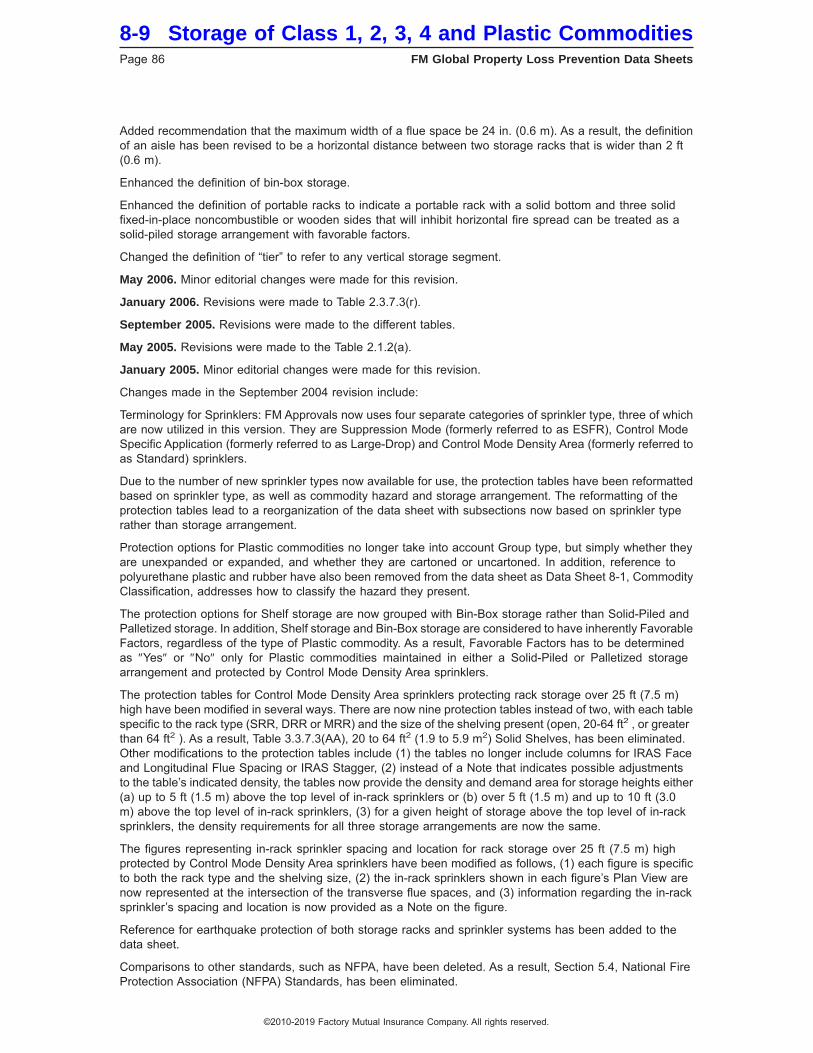
Added recommendation that the maximum width of a flue space be 24 in. (0.6 m). As a result, the definitionof an aisle has been revised to be a horizontal distance between two storage racks that is wider than 2 ft(0.6 m).
Enhanced the definition of bin-box storage.
Enhanced the definition of portable racks to indicate a portable rack with a solid bottom and three solidfixed-in-place noncombustible or wooden sides that will inhibit horizontal fire spread can be treated as asolid-piled storage arrangement with favorable factors.
Changed the definition of “tier” to refer to any vertical storage segment.
May 2006. Minor editorial changes were made for this revision.
January 2006. Revisions were made to Table 2.3.7.3(r).
September 2005. Revisions were made to the different tables.
May 2005. Revisions were made to the Table 2.1.2(a).
January 2005. Minor editorial changes were made for this revision.
Changes made in the September 2004 revision include:
Terminology for Sprinklers: FM Approvals now uses four separate categories of sprinkler type, three of whichare now utilized in this version. They are Suppression Mode (formerly referred to as ESFR), Control ModeSpecific Application (formerly referred to as Large-Drop) and Control Mode Density Area (formerly referred toas Standard) sprinklers.
Due to the number of new sprinkler types now available for use, the protection tables have been reformattedbased on sprinkler type, as well as commodity hazard and storage arrangement. The reformatting of theprotection tables lead to a reorganization of the data sheet with subsections now based on sprinkler typerather than storage arrangement.
Protection options for Plastic commodities no longer take into account Group type, but simply whether theyare unexpanded or expanded, and whether they are cartoned or uncartoned. In addition, reference topolyurethane plastic and rubber have also been removed from the data sheet as Data Sheet 8-1, CommodityClassification, addresses how to classify the hazard they present.
The protection options for Shelf storage are now grouped with Bin-Box storage rather than Solid-Piled andPalletized storage. In addition, Shelf storage and Bin-Box storage are considered to have inherently FavorableFactors, regardless of the type of Plastic commodity. As a result, Favorable Factors has to be determinedas ″Yes″ or ″No″ only for Plastic commodities maintained in either a Solid-Piled or Palletized storagearrangement and protected by Control Mode Density Area sprinklers.
The protection tables for Control Mode Density Area sprinklers protecting rack storage over 25 ft (7.5 m)high have been modified in several ways. There are now nine protection tables instead of two, with each tablespecific to the rack type (SRR, DRR or MRR) and the size of the shelving present (open, 20-64 ft2 , or greaterthan 64 ft2 ). As a result, Table 3.3.7.3(AA), 20 to 64 ft2 (1.9 to 5.9 m2) Solid Shelves, has been eliminated.Other modifications to the protection tables include (1) the tables no longer include columns for IRAS Faceand Longitudinal Flue Spacing or IRAS Stagger, (2) instead of a Note that indicates possible adjustmentsto the table’s indicated density, the tables now provide the density and demand area for storage heights either(a) up to 5 ft (1.5 m) above the top level of in-rack sprinklers or (b) over 5 ft (1.5 m) and up to 10 ft (3.0m) above the top level of in-rack sprinklers, (3) for a given height of storage above the top level of in-racksprinklers, the density requirements for all three storage arrangements are now the same.
The figures representing in-rack sprinkler spacing and location for rack storage over 25 ft (7.5 m) highprotected by Control Mode Density Area sprinklers have been modified as follows, (1) each figure is specificto both the rack type and the shelving size, (2) the in-rack sprinklers shown in each figure’s Plan View arenow represented at the intersection of the transverse flue spaces, and (3) information regarding the in-racksprinkler’s spacing and location is now provided as a Note on the figure.
Reference for earthquake protection of both storage racks and sprinkler systems has been added to thedata sheet.
Comparisons to other standards, such as NFPA, have been deleted. As a result, Section 5.4, National FireProtection Association (NFPA) Standards, has been eliminated.
8-9 Storage of Class 1, 2, 3, 4 and Plastic CommoditiesPage 86 FM Global Property Loss Prevention Data Sheets
©2010-2019 Factory Mutual Insurance Company. All rights reserved.
Metric values provided in this version of the data sheet have been modified, as needed, so they are nowbased on ″realistic″ and ″design desired″ values instead of strict mathematical conversion values.
New protection options have been provided within the protection tables for all storage arrangements involvingControl Mode Specific Application sprinklers to account for excessive clearance. In addition, new protectionoptions have been provided within the protection tables for solid-piled, palletized, shelf and bin-box storagearrangements protected by Control Mode Density Area sprinklers to account for excessive clearance.
In an effort to simplify the options available to the user, new supporting tables have been created for thehazard associated with Open-Top Combustible Containers (all sprinkler types) and Excessive Clearance(Control Mode Density Area). In addition, two new options have been added to the new Excessive Clearancetable to help account for excessive clearance involving Control Mode Density Area sprinklers.
A new supporting table has been created that provides the required density and demand area for ceiling-levelControl Mode Density Area sprinklers when extra levels of in-rack sprinklers are provided. This table replacesthe previous Table 3.3.7.2(AA), Ceiling Sprinkler Density Adjustments, which provided guidelines on howto adjust the density obtained from a protection table. As a result, an adjustment to the existing densityobtained from the protection tables is no longer necessary due to the presence of extra levels of in-racksprinklers.
The wording previously listed in Section 3.3.4, In-Rack Sprinklers (IRAS), has been amended to stress thecritical importance of locating the in-rack sprinklers at the intersection of flue spaces as well as providinga proper stagger for multiple in-rack sprinkler levels in the absence of horizontal barriers.
The protection option known as ″Scheme A″ from Data Sheet 7-29 has been incorporated into this versionof the data sheet as a means of isolating and protecting small amounts of high hazard commodities thatcannot be protected by the existing or proposed sprinkler systems. The design provided in Data Sheet 7-29has been modified for this data sheet as follows: (1) the number of in-rack sprinklers flowing is based on6 sprinklers if the rack to be protected with Scheme A protection is single-row, or 8 sprinklers if the protectedrack is double- or multiple-row; (2) the number of in-rack sprinklers in the design is not tied to a numberof sprinklers flowing on 2 lines; (3) the design is based on a minimum flow of 60 gpm (230 L/min) insteadof 50 psi (3.5 bar); and (4) the use of FM Approved K11.2 (K160) quick-response sprinklers are permitted inaddition to FM Approved K8.0 (K115) quick-response sprinklers.
The minimum operating pressure for all Control Mode Density Area sprinklers is now 7 psi (0.5 bar).
The horizontal and vertical spacing for in-rack sprinklers is now consistent throughout the data sheetregardless of storage height or aisle width.
The previous Section 3.3.7.2.3, Special Procedure for Evaluating Existing Systems Using Standard or ELOSprinklers to Protect Class 1-4 Commodities and Which Have Ceiling Sprinkler Design Areas Other than2000 ft2 (186 m2) for Wet Pipe Systems, or 2,600 ft2 (242 m2) for Dry-Pipe Systems (and Preaction SystemsTreated as Dry-Pipe Systems), has been eliminated.
Table 3.3.7.4(AA), Suppression Mode (ESFR) Automatic Sprinkler Protection for Plastic Commodities, hasbeen eliminated since the information it contained has been incorporated into the new protection tables.
Table 3.3.3.2, Extension Design Area for 286°F (141°C) Sprinklers, has been eliminated. The data sheet nowrecommends that the extension of the design and the sprinkler type protecting the area with the higher hazardbe the same.
Tables 3.3.7.2, Rack Storage Up Through 25 ft (7.6 m) High, and 3.3.7.4, Solid-Piled, Palletized, Shelf andBin-Box Storage, have been eliminated due to the reorganization of the data sheet.
Any information that is not specific to this data sheet and is covered in other FM Global data sheets hasbeen eliminated. As a result, information previously provided in Sections 3.1.2, Roof Construction, 3.1.3, RoofSlope, 3.3.4.6, In-Rack Sprinkler Piping, 3.3.4.7, In-Rack Sprinkler Control Valves, 3.3.4.8, In-Rack SprinklerSystem Size, 3.3.4.9, In-Rack Sprinkler System Waterflow Alarms and Test Connections, and Figure 3.3.4.7,Supply pipe arrangement to sprinklers at ceiling and in-racks, have been eliminated. In addition, the locationrequirements of heat detection for pre-action in-rack sprinkler systems has also been eliminated and replacedby the appropriate reference in other data sheets.
As a supplement to the two existing figures representing in-rack sprinkler protection for multiple-row rackstorage up to 25 ft (7.5 m) high, two new figures were added. They include (1) a second option of in-racksprinklers when the protection tables indicate that more than one level of in-rack sprinklers is required, and
Storage of Class 1, 2, 3, 4 and Plastic Commodities 8-9FM Global Property Loss Prevention Data Sheets Page 87
©2010-2019 Factory Mutual Insurance Company. All rights reserved.

(2) a representation of the in-rack sprinkler arrangement when solid shelves greater than 64 ft2 (6.0 m2) arepresent. In addition, Figure 2.3.4.2(b) has been modified so that all the ″X″ in-rack sprinklers are at the topof the second tier level and all of the ″triangle″ in-rack sprinklers are at the top of the fourth tier level, in orderto reduce the cost of the installation to a FM Global client while at the same time offering the same level ofin-rack sprinkler protection.
Former Figure 3.3.7.3(k), which is now Figure 2.3.7.3(l), has been clarified that it applies only to wet-pipesprinkler systems.
Section 2.1.1, General, has been enhanced to include a recommendation for proper anchorage of the storageracks.
Table 2.1.3.1, Acceptable Types of Heat and Smoke Vents, has been modified to account for a new FMApproved drop-out heat vent that is acceptable in the presence of Suppression Mode sprinklers. In addition,the recommendation to provide an additional sprinkler under the center of a vent that cannot be equippedwith a temperature link per Table 2.1.3.1 has been amended to say that the additional sprinkler should bequick-response.
The definition of ″Flue Spaces″ in Section 2.2.2 and Appendix A has been enhanced to include the minimumclear space needed in order to be considered acceptable for rack storage shelving purposes.
The requirement of longitudinal flue spaces for double-row racks over 25 ft (7.5 m) high has been eliminatedfrom Section 3.2.2, Flue Spaces, Pile Stability, Product Spillage and Product Form. However, this is onlypermissible as long as there are no longitudinal flue spaces for the entire vertical height of the rack.
Portable racks were added to former Section 3.2.4 (now Section 2.2.4), Special Storage Considerations,and provided with additional guidance to define when they can be treated and protected as open-frame(multiple-row) racks.
The term ″Single-Row Rack″ was eliminated from any reference for racks wider than 9 ft (2.7 m) in Section3.3.4.2.1, Open-Frame Racks with No Solid Shelves, since a single-row rack cannot be this wide.
Additional information has been provided in Section 2.3.7.3.4, Favorable vs. No Favorable Factors, to helpbetter clarify the term Favorable Factors.
Section 2.0, General, has been deleted and the definition of terms has been relocated to Appendix A.
The section on Interpolation for Control Mode Density Area sprinklers has been modified to include anequation for interpolation.
The definition for ″Aisle″ in Appendix A has been enhanced to include the minimum acceptable width of 4ft (1.2 m) so that it is consistent throughout the data sheet.
The definition for ″Clearance″ in Appendix A has been enhanced to include and define the term ″excessiveclearance″.
The definition of ″Rack Storage″ in Appendix A has been modified so that a minimum distance of 4 ft (1.2m) is now required to avoid single-row or double-row racks as being treated as multiple-row racks, thedefinition for portable racks has been enhanced to stress the need for acceptable flue spaces in order to betreated as open-frame (multiple-row) racks, grating must be a minimum of 70%to be considered open-frame,and slatted shelves that are not fixed-in-place automatically default to solid shelves.
The definition of ″Rack Storage Sprinklers″ in Appendix A has been enhanced to stress the importance oflocating the sprinklers at the intersection of flue spaces and providing, when required, vertical stagger.
The definition of ″Solid Shelving″ in Appendix A has been enhanced to stress the need for openings at thetransverse flue spaces in order to be considered open-frame racks.
Efforts were made to eliminate as many notes as possible from the protection tables.
May 2003. Minor editorial changes were made.
January 2003. Recommendation 3.3.3.5 Storage Clearance added.
September 2002. The following new sections have been added:
Section 3.3.8.5 was added to incorporate the guidelines for the K22.4 suppression mode sprinkler previouslycovered in Engineering Bulletin #06-01.
8-9 Storage of Class 1, 2, 3, 4 and Plastic CommoditiesPage 88 FM Global Property Loss Prevention Data Sheets
©2010-2019 Factory Mutual Insurance Company. All rights reserved.
Section 3.3.8.6 was added to incorporate the guidelines for the newly Approved TYCO Model TY7126 K16.8Upright Suppression Mode Sprinkler.
September 2001. In line with the changes described in Section 1.2, item 1, under ″Changes made in theMay 2001 Revision,″ the following changes are incorporated into the September 2001 version:
1. In Tables 3.3.7.2(a), (d), (g), and (j), in the ESFR column for all four storage heights and building heightof 45 ft (13.5 m), replaced “12 @ 90 psi (6.1 bar)” with “DNA.”
2. In Table 3.3.7.2(m), in the ESFR column for all four storage heights and building height of 45 ft (13.5 m),replaced “Note 13” with “DNA,” and also deleted Note 13 that follows that table.
Note: “12 @ 90 psi (6.1 bar)” entries in Table 3.3.7.4(a) through (d) for solid-piled/palletized storage to 35ft (10.5 m) in 45 ft (13.5 m) buildings remain valid as the change made in the May 2001 version applied onlyto rack storage.
May 2001. The following changes were made:
1. The guidelines in Section 3.3.7.3, item 1, part b for protecting storage of Class 1-4, and cartoned anduncartoned unexpanded plastic commodities in buildings over 40 ft (12.0 m) up to 45 ft (13.5 m) using K14.0(K200) pendent suppression mode sprinklers at the ceiling only, have been rescinded as a result of recenttesting. Item 1, part C has been renumbered as part b. Storage of Class 1-4 and cartoned unexpanded plasticcommodities in 45 ft (13.5 m) high buildings can be protected by K25.2 (K360) suppression mode sprinklersat the ceiling only as outlined in Section 3.3.8.1. There is no longer a method for protecting uncartonedunexpanded plastic storage in buildings higher than 40 ft (12.0 m) with suppression mode sprinklers at theceiling only.
2. A new Section 3.3.8.4 has been added to incorporate the guidelines for the K16.8 (K240) suppressionmode sprinkler previously covered in Engineering Bulletin #15-00.
3. A new Section 3.3.8.5 has been added to incorporate guidelines for the upright K14.0 (K200) suppressionmode sprinkler previously covered in Engineering Bulletin #14-00.
May 2000. The following changes were made:
1. New text is added in Section 2.2.2.1 to address flue spaces blocked by rolls of fabric, fiber or other materialsand that create a solid shelf effect.
2. Tables 3.3.7.2(i), (l), (o) and (r) are revised to recommend in-rack sprinklers for racks up to 10 ft (3.0 m)high that have solid shelves greater than 64 ft2 (6.0 m2) and are used to store Class 3, 4 and plasticcommodities.
3. New guidelines are added in Section 3.3.8.1 for K25.2 (K360) suppression mode sprinklers to protectuncartoned unexpanded plastic storage.
September 1999. The following changes were made:
1. Guidelines for K-factor 25.2 (360) suppression mode sprinklers and for K-factor 16.8 (240) CMSA sprinklershas been relocated to new Section 3.3.8.
2. Engineering Bulletin 5-99, ‘‘K-factor 25.2 Suppression Mode Sprinklers for Exposed Expanded Polystyreneand Polyurethane in Closed Array Palletized or Solid-Piled Storage,’’ dated June 7, 1999, has beenincorporated in Section 3.3.8.
March 1997. The following changes were made:
1. Guidelines for use of suppression mode sprinklers in buildings up to 45 ft (13.5 m) high have been added.Note the limits on storage height and commodity, and required design pressures as covered in the appropriatetables and text. Commodity is limited to cartoned and uncartoned unexpanded plastic or less, and storageheight is limited to 35 ft (10.5 m) for palletized / solid-piled storage and open-frame rack storage without in-racksprinklers, and to 40 ft (12.0 m) open-frame rack storage when one level of quick-response in-rack sprinklersare installed per data sheet guidelines.
2. Figure 3.3.7.3(k) and the associated Table 3.3.7.3(a) reference have been changed to allow 9 ft (2.7 m)wide racks to accommodate common non-North American rack designs and pallet dimensions.
Storage of Class 1, 2, 3, 4 and Plastic Commodities 8-9FM Global Property Loss Prevention Data Sheets Page 89
©2010-2019 Factory Mutual Insurance Company. All rights reserved.

![Fire Protection - SmartCockpit A319-320-321 [Fire Protection] Page 1. Airbus A319-320-321 [Fire Protection] ... [Fire Protection] Page 46. Airbus A319-320-321 [Fire Protection] Page](https://img.pdfslide.us/doc/110x75/5aaae6367f8b9a6c188ed0d4/fire-protection-a319-320-321-fire-protection-page-1-airbus-a319-320-321-fire.jpg)