Embed Size (px)
Citation preview

8/11/2019 UCSguru.com _ Every Cloud Has a Tin Lining
http://slidepdf.com/reader/full/ucsgurucom-every-cloud-has-a-tin-lining 1/24
9/25/2014 UCSguru.com | Every Cloud Has a Tin Lining.
http://ucsguru.com/ 1
Cisco UCS New M4 Additions!Posted on September 8, 2014
Following on from last weeks big announcements and the teaser on the new M4 line-up I am pleased to say I can
now post the details of that new line-up.
The new M4 servers, are based on the Intel Grantley-EP Platform, incorporating the latest Intel E5-2600 v3
(Haswell EP) processors. These new processors are availa ble with up to an incredible 18 Cores per socket and
support memory speeds up to a blistering 2133MHz.
Which in real terms means far denser virtualised environments and higher performing bare metal environments,
which equates to less compute nodes required for the same job, and all the other efficiencies having a reduced
footprint brings.
The new models being announced today are:
New M4 line-up
C220M4
The stand out details for me here, are that the two new members of the C-Series Rack Mount family now come
with a Modular LAN on Motherboard (mLOM) the VIC 1227 (SFP) and the VIC 1227T (10GBaseT). Which means
this frees up a valuable PCIe 3.0 slot.
The C220M4 has an additional 2 x PCIe 3.0 Slots which could be used for additional I/O like the VIC1285 40Gb
adapter or the new Gen 3 40Gb VIC1385 adapter. The PCIe slots also support Graphic Processing Units (GPU) for
graphics intensive VDI solutions as well as PCIe Flash based UCS Storage accelerators.
UCSguru.com

8/11/2019 UCSguru.com _ Every Cloud Has a Tin Lining
http://slidepdf.com/reader/full/ucsgurucom-every-cloud-has-a-tin-lining 2/24
9/25/2014 UCSguru.com | Every Cloud Has a Tin Lining.
http://ucsguru.com/ 2
C240M4
In addition to all the goodness you get with the C220 the C240 offers 6 PCIe 3.0 Slots, 4 of which are full height,
full length which should really open up the 3rd party card offerings.
Also worth noting that in addition to the standard Cisco Flexible Flash SD cards, the C240 M4 also has an optional
2 internal small form factor (SFF) SATA drives. Ideal if you want to keep a large foot printed operating system
physically separate from your front facing drives.
B200M4
And now for my favourite member of the Cisco UCS Server family, the trusty, versatile B200, great to see this
blade get “pimped” with all the M4 goodness, as well as some great additional innovation.

8/11/2019 UCSguru.com _ Every Cloud Has a Tin Lining
http://slidepdf.com/reader/full/ucsgurucom-every-cloud-has-a-tin-lining 3/24
9/25/2014 UCSguru.com | Every Cloud Has a Tin Lining.
http://ucsguru.com/ 3
So on top of the E5-2600v3 CPU’s supporting up to 18 Cores per socket, the ultra-fast 2133MHz DDR4 Memory,
as well as the new 40Gb ready VIC 1340 mLOM, what I quite like about the B200M4 is the new “FlexStorage”
Modular storage system.
Many of my clients love the statelessness aspects of Cisco UCS and to exploit this to the Max, most remote boot.
And while none of them have ever said, “Colin it’s a bit of a waste, I’m having to pay for, and power an embedded
RAID controller, when I’m not even using it”, well now they don’t have to, as the drives and storage controllers are
now modular and can be ordered separately if required, or omitted completely if not.
But if after re-mortgaging your house you still can’t afford the very pricey DDR4 Memory, worry ye not, as the M3
DDR3 Blades and Rack mounts certainly aren’t going anywhere, anytime soon.
Until next time.
Take care of that Data Center of yours!
Colin
Share this:
Twitter 18
Posted in Product Updates | 2 Comments
Cisco UCS: Major AnnouncementPosted on September 4, 2014
Hi All
It’s finally September the 4th which means only one thing, the biggest single day of Cisco UCS announcements
since the products launch 5 years ago.
The strapline of the launch is “Computing at every scale” And “Scale” both large and small is certainly the
Like
One blogger likes this.
8/11/2019 UCSguru.com _ Every Cloud Has a Tin Lining
http://slidepdf.com/reader/full/ucsgurucom-every-cloud-has-a-tin-lining 4/24
9/25/2014 UCSguru.com | Every Cloud Has a Tin Lining.
http://ucsguru.com/ 4
consistent messaging with all the new announcements.
UCS Mini
In a previous post (which can be found here) I did quite a comprehensive write up on the Cisco UCS 6324 Fabric
Interconnect and Next Gen UCS Chassis, so I won’t go into the technical details again, but today Cisco officially
unveil their vision for what they have now branded “UCS Mini”.
As mentioned the theme today is scale, and as we know, a significant percentage of servers in use today are
outside of the Data Center, these use cases may be large companies with branch offices, retail outlets, remote data
collection points or any use case where the Compute needs to be close to the demand.
And then there is another requirement where a smaller company simply wants a ready assembled and simplified
“All-in-One” solution. In either case a more “non Data Center” friendly platform is required.
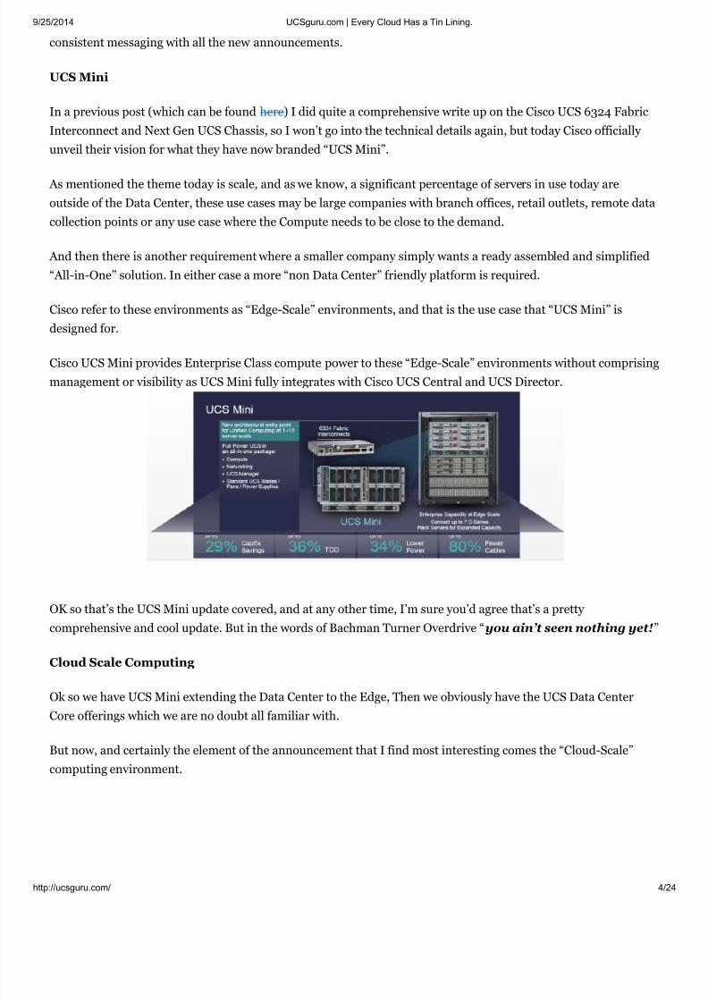
Cisco refer to these environments as “Edge-Scale” environments, and that is the use case that “UCS Mini” is
designed for.
Cisco UCS Mini provides Enterprise Class compute power to these “Edge-Scale” environments without comprising
management or visibility as UCS Mini fully integrates with Cisco UCS Central and UCS Director.
OK so that’s the UCS Mini update covered, and at any other time, I’m sure you’d agree that’s a pretty
comprehensive and cool update. But in the words of Bachman Turner Overdrive “you ain’t seen nothing yet!”
Cloud Scale Computing
Ok so we have UCS Mini extending the Data Center to the Edge, Then we obviously have the UCS Data CenterCore offerings which we are no doubt all familiar with.
But now, and certainly the element of the announcement that I find most interesting comes the “Cloud-Scale”
computing environment.

8/11/2019 UCSguru.com _ Every Cloud Has a Tin Lining
http://slidepdf.com/reader/full/ucsgurucom-every-cloud-has-a-tin-lining 5/24
9/25/2014 UCSguru.com | Every Cloud Has a Tin Lining.
http://ucsguru.com/ 5
In the Enterprise we traditionally see either a 1 to 1 relationship between a server and an application or in the case
of a Hypervisor a single physical server may host many applications.
In the world of “Cloud-Scale” Computing the reverse is true there is a single application utilising many servers.
Examples of these Cloud-Scale models are Analytics, E-Gaming, eCommerice to name but a few.
The key with these applications is to be able to scale the compute while at the same time adding minimal overhead
and things you don’t necessarily need, like fans, power supplies and peripherals etc… and even elements like
storage and I/O if they are not the points of constraint.
I don’t need to tell you how much of this potentially unnecessary “overhead” would be in a rack of 16 1U servers,
each with redundant NICs, Fans, Power supplies and so on.
True a Blade solution does alleviate this overhead to some degree, but is still isn’t designed specifically for the use
case.
So if both C-Series and B-Series are not perfectly aligned to the task what is?
The answer is the new M-Series Modular Servers.
A single M-Series M4308 Modular Chassis, can give you the same CPU density as the 16 x 1U Rack Mount servers
in the example above but with a fraction of the “overhead”, allowing for true Compute Cloud-Scaling and all
within a 2RU chassis.

8/11/2019 UCSguru.com _ Every Cloud Has a Tin Lining
http://slidepdf.com/reader/full/ucsgurucom-every-cloud-has-a-tin-lining 6/24
9/25/2014 UCSguru.com | Every Cloud Has a Tin Lining.
http://ucsguru.com/ 6
Each 2RU M-Series Chassis can contain up to 8 front loading UCS M142 “Compute Cartridges” and each Compute
Cartridge contains 2 independent Compute Nodes, each with a single Intel XEON 4Core E3 processor and 32GB
RAM (4 DIMM Slots), with no Network Adapters, No storage and no peripherals. Just raw Compute and Memory.
The Storage and I/O in the back of the Chassis is completely independent from the Compute Cartridges and acts
as a shared resource available to them all. This separation is made possible by a innovation called “Cisco System
Link Technology” This server “Disaggregation” negates the usual issues of sub-optimal CPU to Storage and IO
ratios and allows both to be independently scaled to the requirement.
A 3rd Generation Cisco VIC provides the internal fabric through which all components communicate as well as
providing the dual 40Gb external connectivity to the Fabric Interconnects.
The 4 SSD’s allow up to 6.4TB of local storage. which is configured in a RAID group and logically divided amongst
the Compute Nodes within the cartridges, which just see a locally attached SCSI LUN.
At FCS it will not be possible to mix current B and C Series UCS servers with the M-Series which will need a
dedicated pair of 6200 Fabric Interconnects.
A single UCS Domain can scale to 20 M-Series Chassis along with all the associated Cartridges and Compute
Nodes (Giving the grand total of 320 Supported Servers).
At first glance the M-Series may look a bit “Nutanixy” however Nutanix is a “Hyper-converged” architecture rather
than a “Disaggregated” Architecture, what’s the difference?
well that a fun post for another day.
NB) Earlier this month Cisco did announce a deal with Simplivity to address the “Hyper-converged” market
A better comparison to the Cisco UCS M-Series would be the HP Moonshot and Cisco are confident that the M-Series has many advantages over Moonshot.
C3000 Rack Storage Server
Lastly but certainly not least is the Cisco C3160, a Stand-a-lone Server completely optimised for storage. The
C3160 would be ideal to provide the complimentary storage capacity for the M-Series compute nodes, but could
equally provide storage to UCS B-Series Blades and UCS C-Series Rack mounts (up to 240TB per 4U Server at
FCS utilising 4TB drives, ).
Where the M-series provides the transactional front end, the C3160 provides the storage for context and content.
Typical use cases for the C3160 in conjunction with the M-Series servers would be a Big Data type application.
This combination is also well suited to an Open stack environment with the M-Series serving as the Compute
Nodes (Nova) and the C3160 would serve as the Storage node running Cephs.
The management for the C3160 is provided by a Cisco IMC, just like using a stand-a-lone C-Series today, and
while I don’t know, I would think UCS Manager integration would be a great and logical future update.
All storage within the C3160 is presented and owned locally by the server (Dual E5-2600v2, with up to 256GB

8/11/2019 UCSguru.com _ Every Cloud Has a Tin Lining
http://slidepdf.com/reader/full/ucsgurucom-every-cloud-has-a-tin-lining 7/24
9/25/2014 UCSguru.com | Every Cloud Has a Tin Lining.
http://ucsguru.com/ 7
DDR3 RAM at FCS), A mirrored pair of SFF SSD’s are available for an operating system which can then just farm
out the storage via the protocol of choice.
A great point about the C3160 is that it is not only 4RU high but at 31.8 inches deep will fit into a standard depth
rack.
Anyway, huge update this one, awesome job Cisco! and congratulations, and I for one am certainly looking
forward to having a good play with all these new products.
And as a Teaser to next weeks official announcements of the new M4 line-up, I can give you a sneak peek below,
but tune in on the 8th September, Same UCS Time, same UCS channel, when we’ll take a look under these covers
as there are a few surprises lurking beneath.
Until next time
And take care of that Data Center of yours!
Colin
Share this:
8/11/2019 UCSguru.com _ Every Cloud Has a Tin Lining
http://slidepdf.com/reader/full/ucsgurucom-every-cloud-has-a-tin-lining 8/24
9/25/2014 UCSguru.com | Every Cloud Has a Tin Lining.
http://ucsguru.com/ 8
Twitter 81
Posted in Product Updates | Tagged 6324, B200M4, C3160, Cisco, e5-2600v3, haswell, M Series, M4, UCS mini | 1 Comment
Unification Part 2: FCoE DemystifiedPosted on September 3, 2014
As promised here is the 2nd part of the Unified Fabric post, where we get under the covers with FCoE.
The first and most important thing to clarify is as its name suggests Fibre Channel over Ethernet (FCoE) still uses
the Fibre Channel protocol, and as such all the higher level processes that needed to happen in a Native Fibre
Channel environment FLOGI/PLOGI etc., still need to happen in an FCoE environment.
So having a good understanding of Native Fibre Channel operations is key. So let’s start with a quick Native Fibre
Channel recap:
For the IP Networker I have put some parentheses () and corresponding IP services that can be very loosely mapped to the Fibre Channel process to aid understanding.
Native Fibre Channel
Initiators/Targets contain Host Bus Adapters (HBA’s) which in Fibre Channel terms are referred to as Node ports
(N ports).
These N Ports are connected to Fabric Ports (F ports) on the Fibre Channel switches.
Fibre Channel switches are then in turn connected together via Expansion (E) Ports, or if both Switches are Cisco you have the option of also Trunking multiple Virtual SANs (VSANs) over the E ports in which case they become
Trunking Expansion Ports (TE Ports).
First the initiator (server) sends out a Fabric Login (FLOGI) to the well-known address FFFFFE, this FLOGI
registers the unique 64bit World Wide Port Name (WWPN) of the HBA (Think MAC Address) with the Fibre
Channel Name Server (FCNS).
The FCNS is a service that automatically runs on an elected “Principal switch” within the Fabric. By default the
switch with the lowest Domain ID in the Fabric is elected the Principal Switch.
The Principal Switch is also in charge of issuing the Domain ID’s to all the other switches in the Fabric.
The FCNS then sends the initiator back a unique 24bit routable Fibre Channel Identifier (FC_ID) also referred to
as an N_Port_ID (Think IP Address) the 24bit FC_ID is expressed as 6 Hexadecimal digits.
So the basic FLOGI conversation goes something like “Here’s my unique burned in address” send me my routable
address (think DHCP)
The 24bit FC_ID is made up of 3 parts:
Like
Be the first to like this.

8/11/2019 UCSguru.com _ Every Cloud Has a Tin Lining
http://slidepdf.com/reader/full/ucsgurucom-every-cloud-has-a-tin-lining 9/24
9/25/2014 UCSguru.com | Every Cloud Has a Tin Lining.
http://ucsguru.com/ 9
• The Domain ID, which is assigned by the Principal switch to the Fibre Channel switch, to which the host
connects.
• The Area ID, which actually is the port number of the switch the HBA is connected to.
• The Port ID which refers to the single port address on the actual host HBA.
The above format ensures FC_ID uniqueness within the fabric.
Figure 1 Fibre Channel Identifier
Once the initiator receives its FC_ID, it then sends a Port Login (PLOGI) to well-known address FFFFFC which
registers its WWPN and assigned FC_ID with the Fibre Channel Name Server (FCNS). (Think of the FCNS Server
like DNS). The FCNS then returns all the FCID’s of the Targets the initiator has been allowed to access via the
Zoning policy.
Once the PLOGI is completed, the initiator starts a discovery process, to find the Logical Unit Numbers (LUNs) it
has access to.
The FLOGI database is locally significant to the switch and only shows WWPN’s and FC_ID’s of directly attached
Initiators/Targets, the FCNS database on the other hand is distributed across all switches in the fabric, and shows
all reachable WWPN’s and FC_ID’s within the Fabric.

8/11/2019 UCSguru.com _ Every Cloud Has a Tin Lining
http://slidepdf.com/reader/full/ucsgurucom-every-cloud-has-a-tin-lining 10/24
9/25/2014 UCSguru.com | Every Cloud Has a Tin Lining.
http://ucsguru.com/ 10
Figure 2 Native Fibre Channel Topology.
OK History lesson over.
The Fibre Channel protocol has long proven to be the best choice for block based storage (storage that appears as
locally connected), and FCoE simply takes all that tried and tested Fibre Channel performance and stability, and
offers an alternative layer one physical transport in this case Ethernet.
But replacing the Fibre Channel transport, did come with its challenges, The Fibre Channel physical layer creates
a “lossless” medium by using buffer credits; think of a line of people passing boxes down the line, and if the next
person does not have empty hands (available buffer), they cannot receive the next box, so the flow is “paused”
until the box can again be passed.
Ethernet on the other hand expects drops and uses windowing by upper layer protocols in order to not over whelm the receiver, instead of a line of people passing a box from hand to hand, think of a conveyor belt with
someone just loading boxes on it, at an ever increasing speed, until they hear shouts from the other end that boxes
are falling off, at which point they slow their loading rate and gradually speed up again.
So the million dollar question was how to send a “lossless” payload over a “lossy” transport.
The answer to which, was several enhancements to the Ethernet Standard generally and collectively referred to as
Data Centre Bridging (DCB)

8/11/2019 UCSguru.com _ Every Cloud Has a Tin Lining
http://slidepdf.com/reader/full/ucsgurucom-every-cloud-has-a-tin-lining 11/24
9/25/2014 UCSguru.com | Every Cloud Has a Tin Lining.
http://ucsguru.com/ 11
Fibre Channel over Ethernet
OK so now we have had a quick refresher on Native Fibre Channel, let’s walk through the same process, in the
converged world.
First of all let’s get some terminology out of the way,
End Node (E-Node) the End host in an FCoE network, containing the Converged Network Adapter (CNA) this
could be a Server or FCoE attached Storage Array.
Fibre Channel Forwarder (FCF) Switches that understand both Ethernet and Fibre Channel protocol stacks.
NB) An FCF is required whenever FC encapsulation/de-encapsulation is required. But as an FCoE frame is a legal
tagged Ethernet frame it could be transparently forwarded over standard Ethernet switches.
The next thing to keep in mind is that Fibre Channel and Ethernet work very differently, Ethernet is an open
mulit-access medium, meaning that multiple devices can exist on the same segment and can all talk to each other
without any additional configuration.
Fibre Channel on the other hand is a closed point to point medium , meaning that there should only ever be point
to point links, and hosts by default cannot communicate with each other, without additional configuration called
Zoning (Think Access Control List).
So if you keep in mind that in an FCoE environment we are creating 2 separate logical point to point Fibre
Channel Fabrics (A&B) just like you have in a native Fibre Channel environment, you should be in pretty good
shape to understand what config is required.
So as explained in the Native Fibre Channel refresher above, an N Port in a Host, connects to an F port in a switchand then that switch connects to another Switch via an E port, similarly in the FCoE world we have a Virtual N
Port (VN_Port) which connects to a Vitrual F Port (VF_Port) in the FCF and then if two FCF’s need to be
connected together this is done with Virtual E (VE_Ports).
As can also be seen in the below figure, as the FCF is fully conversant in both Ethernet and Fibre Channel as long
as they have native FC ports configured they can quite happily have native FC initiators and Targets connected to
them.
Follow
Follow“UCSguru.com”
Get every new post delivered
to your Inbox.
Join 2,773 other followers
Enter your email address
Sign me up
Powered by WordPress.com

8/11/2019 UCSguru.com _ Every Cloud Has a Tin Lining
http://slidepdf.com/reader/full/ucsgurucom-every-cloud-has-a-tin-lining 12/24
9/25/2014 UCSguru.com | Every Cloud Has a Tin Lining.
http://ucsguru.com/ 12
Figure 3: Multi-Hop Fibre Channel over Ethernet Topology
So as can be seen above an FCoE Network is a collection of virtual Fibre Channel links, carried over and mapped
onto an Ethernet Transport, but what makes the logical links between the VN_Ports, VF_Ports and VE_Ports? Well a few control protocols are required, collectively known as FCoE Initialisation Protocol (FIP) and it is FIP
which enables the discovery and correct formation of these virtual FC links.
Under each physical FCoE Ethernet port of the FCF a virtual Fibre Channel Port (vfc) is created, and it is the
responsibility of FIP to identify and create the virtual FC link.
Each virtual FC link is identified by 3 values the MAC addresses at either end of the virtual circuit and the FCoE
VLAN ID which carries the encapsulated traffic.
Every FC encapsulated packet must use a VLAN ID dedicated and mapped to that particular VSAN. No IP datatraffic can co-exist on a VLAN designated on the Nexus switch as an FCoE VLAN. If multiple VSANs are in use, a
separate FCoE VLAN is required for each VSAN.
As we know Ethernet has no inherent loss prevention mechanisms, therefore an additional protocol was required
in order to prevent any loss of Fibre Channel packets traversing the Ethernet Links in the event of congestion. A
sub protocol of the Data Centre Bridging standard called Priority Flow Control (PFC) IEEE 802.1Qbb ensures zero
packet loss by providing a link level flow control mechanism that can be controlled independently for each frame
priority. Along with Enhanced Transmission Selection (ETS) IEEE 802.1Qaz which enables the consistent
8/11/2019 UCSguru.com _ Every Cloud Has a Tin Lining
http://slidepdf.com/reader/full/ucsgurucom-every-cloud-has-a-tin-lining 13/24
9/25/2014 UCSguru.com | Every Cloud Has a Tin Lining.
http://ucsguru.com/ 13
management of QoS at the network level by providing consistent scheduling.
Fibre Channel encapsulated frames are marked with an Ethertype of 0x8906 by the CNA and thus can be correctly
identified, queued and prioritised by PFC which places them in a prioritised queue with a Class of Service (CoS)
value of 3 which is the default for encapsulated FC packets. FIP is identified by the Ethertype of 0x8914.
Before the FIP negotiation can start, the physical link needs to come up, this is a job for the Data Centre Bridging
capabilities eXchange (DCBX) protocol, which makes use of the Link Layer Discovery Protocol (LLDP) in order to
configure the CNA with the settings (PFC & ETS) as specified on the switch to which the CNA is connected.
FIP can then establish the virtual FC links between VN_Ports and VF_Ports (ENode to FCF), as well as between
pairs of VE_Ports (FCF to FCF), since these are the only legal combinations supported by native Fibre Channel
fabrics.
Once FIP has established the virtual FC circuit, it identifies the FCoE VLAN in use by the FCF then prompts the
initialisation of FLOGI and Fabric Discovery.
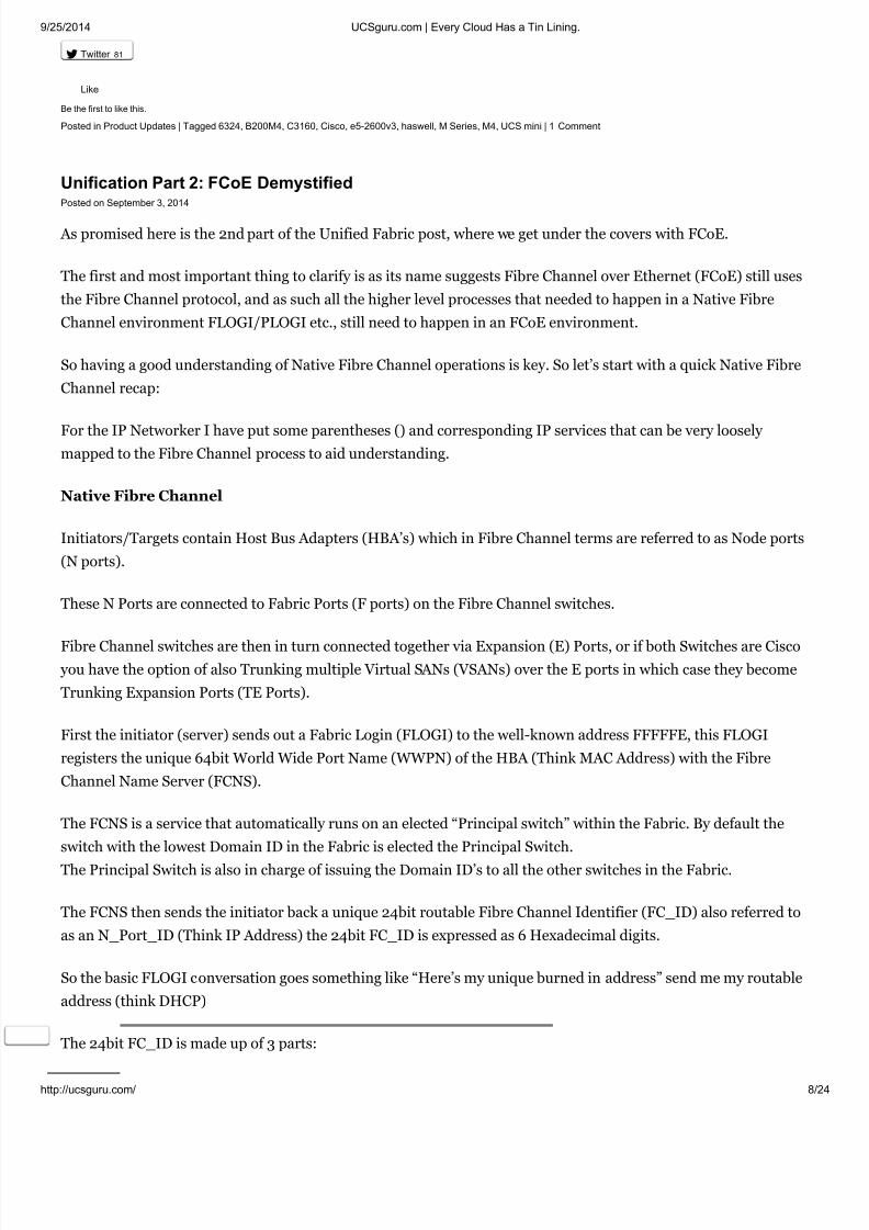
The diagram below shows the FIP initialisation process, the green section is FIP which will identified with theEthertype 0x8914 and the yellow section is FCoE identified with the Ethertype of 0x8906.
It is also worth noting that the E-Node uses different source MAC addresses for FIP and FCoE traffic, FIP traffic is
sourced using the burned in address (BIA) of the CNA whereas the FCoE traffic is sourced using a Fabric Provided
MAC Address (FPMA).
FPMAs are made up from the 24 bit Fibre Channel ID (FC_ID) assigned to the CNA during the FIP FLOGI
process, this 24 bit value is appended to another 24 bit value called the FCoE MAC address prefix (FC-MAP) of
which there are 256 predefined values, but as the FC_ID is unique within the fabric itself, Cisco apply a default
FC-MAP of 0E-FC-00.

8/11/2019 UCSguru.com _ Every Cloud Has a Tin Lining
http://slidepdf.com/reader/full/ucsgurucom-every-cloud-has-a-tin-lining 14/24
9/25/2014 UCSguru.com | Every Cloud Has a Tin Lining.
http://ucsguru.com/ 14
Figure 4 Make-up of the Fabric Provided MAC Address (FPMA)
The fact that FIP and FCoE make use of a tagged FCoE VLAN requires that each Ethernet port configured on the
FCF is configured as a Trunk port, carrying the FCoE VLAN. Along with any required Ethernet VLANs. If the
Server only requires a single VLAN, then this VLAN should be configured as the Native VLAN on the physical
Ethernet port to which the ENode connects.
Ok, it would only be right for me to include a bit on how Cisco UCS fits in to all this.
Well as we know the Cisco UCS Fabric Interconnect by default is in End Host Mode for the Ethernet side of things
and in N-Port Virtualisation (NPV) mode for the storage side of things.
This basically means the Fabric Interconnect appears to the servers as a LAN and SAN switch, but appears to the
upstream LAN and SAN switches as just a big server with lots of HBA’s and NICs inside.
There are many reasons why these are the default values, but the main reasons are around scale, simplicity and
safety. On the LAN side having the FI in EHM prevents the possibility of bridging loops forming between the FI
and upstream LAN switch, And in the case of the SAN, as each FI is pretending to be a Host, the FI does not need
a Fibre Channel Domain ID, neither does it need to participate in all the Fibre Channel Domain Services.
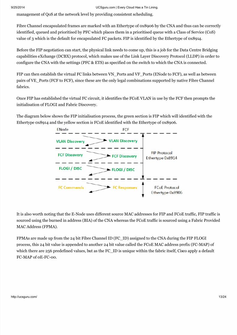
As can be seen from the below Figure in the default NPV mode the Cisco UCS Fabric Interconnect is basically just
a proxy. Its server facing ports are Proxy F ports and its Fabric facing (uplink) ports are Proxy N ports.
Again note no FC Domain ID is required on the Fabric Interconnects.
Also that as we are using Unified Uplinks from the FI to the Nexus (FCF), we cannot use Virtual Port-Channels
to carry the FCoE VLAN, as the FCoE VLAN and corresponding VSAN should only exist on a single Fabric. We
could of course create an Ethernet Only vPC and then have a separate Unified Uplink carrying the FCoE VLAN to
the local upstream Nexus, but if you’re going to do that, you may as well just have stuck with a vPC and Native
Fibre Channel combo.
As would be the case with any multi-VSAN host, the Cisco Nexus ports which are connected to the UCS FI are
configured as Trunking F (TF) ports.
8/11/2019 UCSguru.com _ Every Cloud Has a Tin Lining
http://slidepdf.com/reader/full/ucsgurucom-every-cloud-has-a-tin-lining 15/24
9/25/2014 UCSguru.com | Every Cloud Has a Tin Lining.
http://ucsguru.com/ 15
Figure 5 FCoE with Cisco UCS Unified Uplinks.
Well hope you found this post useful, I’ll certainly be back referencing it myself during the Storage elements of my
CCIE Data Center studies, as it is certainly useful having all elements of a multi-hop FCoE environment, along
with the Native Fibre Channel processes all in a single post.
Until next time.
Colin
Share this:
Twitter 12
Posted in CCIE DC | Tagged Cisco, DCB, DCBX, ETS, fcoe, FIP, FLOGI, Multi-Hop, PFC, PLOGI, UCS | 4 Comments
Unification Part 1: The Rise of the Data Centre Admin.Posted on September 2, 2014
This is the first of a 2-Part Post: Part one is a non-technical primer. Then in part two we have some fun sorting out
your LLDP from your DCBX with sprinkles of ETS, covered in a PFC sauce topped off with a nice FIP cherry.
Part-1
Like
Be the first to like this.
8/11/2019 UCSguru.com _ Every Cloud Has a Tin Lining
http://slidepdf.com/reader/full/ucsgurucom-every-cloud-has-a-tin-lining 16/24
9/25/2014 UCSguru.com | Every Cloud Has a Tin Lining.
http://ucsguru.com/ 16
In this new world of convergence and unification, I seem to spend a lot of my time either teaching “Traditional
Networkers” SAN principals and configuration, or on the other side of the coin teaching “Traditional Storage”
people Networking principals and configuration.
These historically siloed teams are increasingly having to work together in order to create a holistic
unified/converged network.
It is still quite common for me to get requests from clients to create separate “SAN Admin” and “LAN Admin”
accounts on the same Cisco Nexus switch and enforce the privileges of each account via Role Based Access Control
(RBAC), and there is by the way, absolutely, nothing wrong with that, especially if both the LAN and SAN are
complex environments.
However there is an ever increasing overlap and grey area between the roles of the LAN and SAN administrator,
and in a world which is ever focusing on increasing efficiency, simplicity and reduction in support costs, the Role
of “Data Centre Administrator” is on the rise.
I’m glad to say that I very rarely ever get dragged into debates about the validity of FCoE these days, as it has
undoubtedly proven to be a “no brainer” at the edge of the network, with the significant efficiencies in reducedcosts, HBA’s, switch port counts, and all the associated power and cooling reductions that go along with it.
And once the transition to FCoE on the edge is complete, you have to really ask yourself is there any real benefit
maintaining native FC links within the network core, or would it be simpler to just bring everything under the
Ethernet umbrella.
While the efficiencies and savings of a multi-hop FCoE network are not as much of a “no brainer” as it is at the
edge, in my book there’s a lot to be said for just having the same flavour SFP’s throughout the entire network,
along with no need to allocate native FC ports in your Nexus switches or Cisco UCS Fabric Interconnects, (unless
you have FC only Hosts/Arrays somewhere in the network)
In all my years in IT, this topic may well be the one which contains the most abbreviations, DCB, DCBX, LLDP,
PFC, ETS, FIP to name just a few, which I think has led to the perception of complexity, however while there is
certainly a lot of clever tech going on “under the hood” the actual configuration and business as usual tasks are
actually quite simple.
So with all of the above in mind, Part 2 of this post will cover much of the information you need to know as the
“Data Centre Admin” in order to survive in a unified Cisco Nexus Environment.
Share this:
Twitter 3
Posted in General | Tagged Cisco, DCB, DCBX, ETS, fcoe, FIP, Nexus, PFC, unified | Leave a comment
OTV doesn’t kill people, people kill people.
Like
Be the first to like this.

8/11/2019 UCSguru.com _ Every Cloud Has a Tin Lining
http://slidepdf.com/reader/full/ucsgurucom-every-cloud-has-a-tin-lining 17/24
9/25/2014 UCSguru.com | Every Cloud Has a Tin Lining.
http://ucsguru.com/ 17
Posted on July 28, 2014
I was designing a Datacentre migration for one of our clients, they have two DC’s 10km apart connected with some
dark fibre.
Both DC’s were in the south of England but the client needed to vacate the current buildings and move both
Datacentres up north (Circa 300 miles / 500km away) as ever this migration had to be done with minimal
disruption, and at no point should the client be without DR. Meaning we couldn’t simply turn 1 off, load it in a
truck and drive it up north, then repeat for the other one.
The client also had the requirement to maintain 75% service in the event of a single DC going offline. Their current
DC’s were active/active but could support 50% of the load of the other DC if required, meeting this 75% service
availability SLA.
Anyway cutting a long story short I proposed that we located a pair of Cisco ASR 1000’s in one of the southern
DC’s and a pair in each of the northern DC’s and use Cisco’s Overlay Transport Virtualisation (OTV) to extend the
necessary VLANs between all 4 locations for the period of the migration.
As would be expected at this distance, the latency across the MPLS cloud connecting the Southern and Northern
data centres (circa 20ms) was too great to vMotion the workloads, but the VMs could be powered off, cold
migrated and powered back up again in the north. And doing this intelligently DR could be maintained.
The major challenge was that there were dozens of applications and services within these DC’s some of which were
latently sensitive financial applications, along with all the internal fire walling and load balancing that comes
along with them.
The client being still pretty much being a Cisco Catalyst house were unfamiliar with newer concepts like Nexus
and OTV but immediately saw the benefit to this approach, as it allowed a staged migration and great flexibility,
while protecting them from a lot of the issues they were historically vulnerable to, as they had traditionally
extended layer 2 natively across the dark fibre between their two southern Data Centres.
Being a new technology to them, the client understandably had concerns about OTV, in particular around the
potential for suboptimal traffic flows, which could cause their latency sensitive traffic going on unnecessary “field
trips” up and down the country, during the migrationary time period that the North and South DC’s were
connected.

8/11/2019 UCSguru.com _ Every Cloud Has a Tin Lining
http://slidepdf.com/reader/full/ucsgurucom-every-cloud-has-a-tin-lining 18/24
9/25/2014 UCSguru.com | Every Cloud Has a Tin Lining.
http://ucsguru.com/ 18
I was repeatedly asked to re-assure the client about the maturity of OTV and lost count on how many times I had
to whiteboard out the intricacies around how it works, and topics like First Hop Redundancy Protocol isolation
and how broadcast and multi-Cast works over OTV.
My main message though being, “forget about OTV, it’s a means to an end. It’s does what it does, and it does it
very effectively, however it does not replace your brain, there are lots of other considerations to take into account,
all your concerns would be just as valid, if not more so, if I just ran a 500km length of fibre up the country and
extended L2 natively, as the client was already doing, already comfortable with, and had accepted the risksassociated with doing so.
This concept got the client thinking along the right lines, that while OTV certainly facilitated the migration
approach, careful consideration as to what, when, how and the order in which workloads and services were
migrated, would be the crucial factor, which actually had nothing to do with OTV at all.
The point being that an intelligent and responsible use of the technology was the critical factor, and not the
technology itself.
So just remember OTV doesn’t kill people, people kill people.
Stay safe out there.
Colin
Share this:
Twitter 4
Posted in CCIE DC | Tagged Datacenter, Datacentre, migration, OTV, overlay, transport, virtualisation, vMotion | Leave a comment
Cisco UCS has had a baby (Mother and Daughterboard doing well)Posted on July 22, 2014
As many of you know I am now in full CCIE Datacenter study mode, and as such, I never seem to have as much
time to blog and answer posted questions as I would like. However I felt compelled to take a break from my
studies to write a post on the new Cisco UCS generation 3 Fabric Interconnect.
I noticed the other day that Cisco have released the data sheet on the latest member of the Cisco UCS family, theCisco 6324 Fabric Interconnect, which is great because I can now finally blog about it.
http://www.cisco.com/c/en/us/products/collateral/servers-unified-computing/ucs-6300-series-fabric-
interconnects/datasheet-c78-732207.html
Having been waiting for this new FI for a long time, I immediately contacted our purchasing team to get a quote,
with the view to getting one in for our Lab so I can have a good play with it, and I was again pleased to see that the
6324 is listed on Cisco Commerce Workspace (CCW) all-be-it still on New Product Hold.
Like
One blogger likes this.

8/11/2019 UCSguru.com _ Every Cloud Has a Tin Lining
http://slidepdf.com/reader/full/ucsgurucom-every-cloud-has-a-tin-lining 19/24
9/25/2014 UCSguru.com | Every Cloud Has a Tin Lining.
http://ucsguru.com/ 19
The main reason I have been waiting for this product is that it meets a few use cases which historically UCS never
really addressed to the level I wanted with a “full-fat” B-Series deployment, but my customers needed. These use
cases were generally smaller requirements like DMZ or Remote/Branch offices.
Sure, I could use some stand-a-lone C-Series rack mounts, but I really want the power of UCS Manager and to
consolidate all these UCS Domains under UCS Central and integrate them with UCS Director.
And that is where the new Cisco 6324 Fabric Interconnect IO Module comes in, it brings all the power and
features of a full scale UCS Solution, but at the scale and price point that meets these smaller use cases. The best
of both worlds if you like.
So what does this new solution look like?
Well as can be seen from the above data sheet and the below figure, the Fabric Interconnects occupy the IO
Module slots in the Chassis.
5108 v2 Chassis with 6324 FI IOM
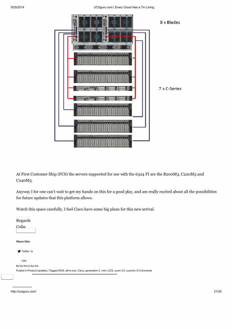
If we look at the new Fabric Interconnect a little closer we see there are 4 x 10G Unified ports and 1 x 40G QSFP+
Port, and as can be seen from the below image there are a number of connectivity options available including
direct attached storage and up to 7 directly attached C Series Rack mount servers, allowing a total of 15 Severs
within the system.

8/11/2019 UCSguru.com _ Every Cloud Has a Tin Lining
http://slidepdf.com/reader/full/ucsgurucom-every-cloud-has-a-tin-lining 20/24
9/25/2014 UCSguru.com | Every Cloud Has a Tin Lining.
http://ucsguru.com/ 20
Internally the 6324 Fabric Interconnect provides 2 x 10Gb Traces (KR Ports) to each half width blade slot (think
2204XP)
But I’m sure you are wondering what happened to the L1 and L2 cluster ports, which would allow two Fabric
Interconnects to cluster and form an HA pair.
Well that explains why there is also a new Chassis being released. This updated 5108 Chassis is fully backwards
compatible, and has hardware support for all past, present and foreseen Fabric Interconnects, IO Modules, Power
Supplies and Servers. Although remember it is actually the version of UCS Manager which determines supported
hardware.
This new chassis not only supports a new Dual Voltage power supply but also comes with a new backplane, and
part of that new back plane, yes you guessed it, are the required traces to support the 1Gbit cluster interconnect
and primary heartbeat between the 6324 Fabric Interconnects. (2104/2204/2208 if used are unaffected).
The secondary heartbeat still runs over the Chassis SEEPROM as per the traditional UCS method (See my
previous post on Cisco UCS HA)
So a new 6324 based solution could look like the following, which I’m sure you’ll agree is more than suitable for all
the use cases I mentioned above.
8/11/2019 UCSguru.com _ Every Cloud Has a Tin Lining
http://slidepdf.com/reader/full/ucsgurucom-every-cloud-has-a-tin-lining 21/24
9/25/2014 UCSguru.com | Every Cloud Has a Tin Lining.
http://ucsguru.com/ 21
At First Customer Ship (FCS) the servers supported for use with the 6324 FI are the B200M3, C220M3 and
C240M3.
Anyway I for one can’t wait to get my hands on this for a good play, and am really excited about all the possibilities
for future updates that this platform allows.
Watch this space carefully, I feel Cisco have some big plans for this new arrival.
Regards
Colin
Share this:
Twitter 36
Posted in Product Updates | Tagged 6324, all-in-one, Cisco, generation 3, mini, UCS, ucsm 3.0, ucsmini | 6 Comments
Like
Be the first to like this.

8/11/2019 UCSguru.com _ Every Cloud Has a Tin Lining
http://slidepdf.com/reader/full/ucsgurucom-every-cloud-has-a-tin-lining 22/24
9/25/2014 UCSguru.com | Every Cloud Has a Tin Lining.
http://ucsguru.com/ 22
The King is Dead, Long live the King!Posted on June 4, 2014
Huge congratulations to Cisco for achieving number 1 in the x86 blade server market in only 5 Years since launch.
Cisco No.1
According to the latest IDC worldwide quarterly Server Tracker (2014 Q1) Cisco UCS which turned 5 years old this
year has hit the number one spot for x86 Server market share in Americas and No.2 worldwide.
To go from zero to No.1 in only 5 years from a standing start is an awesome achievement, and a real credit to all
those involved.
In the 5 years that I have been SME for Cisco UCS, I have seen this traction first hand and still get a great buzz
from seeing the lights switch on when people “get it”
This latest news only gets me more excited about Cisco Application Centric Infrastructure (ACI) as many of the
same great minds that bought us Cisco UCS developed Cisco ACI.
Congrats!
Regards
Colin
Share this:
Twitter 33
Posted in General | Tagged Cisco, HP, IDC, Leader, Market, UCS, x86 | 1 Comment
#EngineersUnplugged ACI Edition with Colin Lynch and Hal Rottenburg
Like
One blogger likes this.
8/11/2019 UCSguru.com _ Every Cloud Has a Tin Lining
http://slidepdf.com/reader/full/ucsgurucom-every-cloud-has-a-tin-lining 23/24
Like
Be the first to like this.
00:00 00:00
Like
Be the first to like this.

8/11/2019 UCSguru.com _ Every Cloud Has a Tin Lining
http://slidepdf.com/reader/full/ucsgurucom-every-cloud-has-a-tin-lining 24/24
Like
Be the first to like this.
The Twenty Ten Theme. Create a free website or blog at WordPress.com.