Embed Size (px)
Citation preview
UCM-Based Generation of Test Goals
Daniel Amyot, University of Ottawa(with Michael Weiss and Luigi Logrippo)[email protected]
RDA Project (funded by NSERC)
Adapted by J-Pierre Corriveau from:
2
…
…
…
…[C1]
[C2]
[C3]
OR-Fork& GuardingConditions
…
…
…
…OR-Join
……
…… …
…
……
AND-JoinAND-Fork
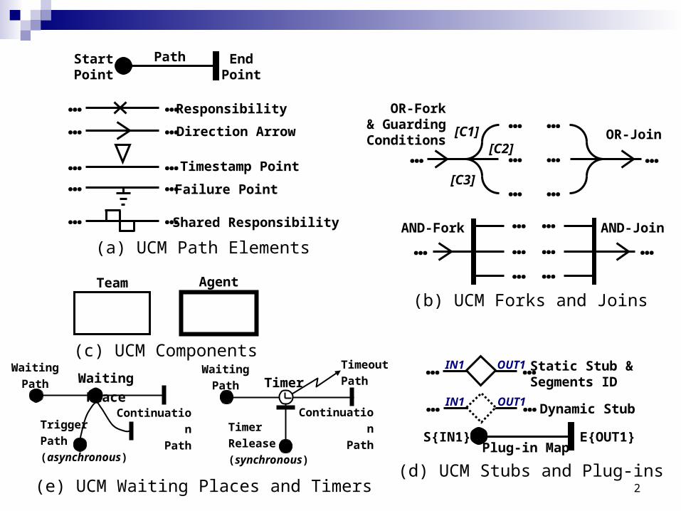
(b) UCM Forks and Joins
StartPoint
EndPoint
Path
… …… … Responsibility
Direction Arrow
… … Timestamp Point
Failure Point… …
Shared Responsibility… …(a) UCM Path Elements
Waiting Place
Trigger
Path
(asynchronous)
Waiting
Path
Continuation
Path
Timer
Timer
Release
(synchronous)
Waiting
Path
Continuation
Path
Timeout
Path
(e) UCM Waiting Places and Timers
… …IN1 OUT1 Static Stub & Segments ID
Dynamic StubIN1 OUT1… …
S{IN1} E{OUT1}
(d) UCM Stubs and Plug-ins
Plug-in Map
(c) UCM Components
Team Agent
3
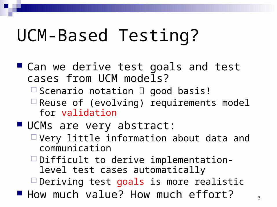
UCM-Based Testing?
Can we derive test goals and test cases from UCM models? Scenario notation good basis! Reuse of (evolving) requirements model for validation
UCMs are very abstract: Very little information about data and communication Difficult to derive implementation-level test cases
automatically Deriving test goals is more realistic
How much value? How much effort?
4
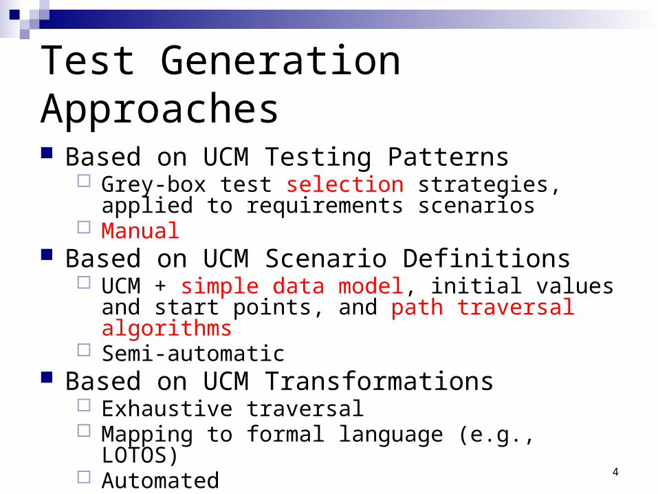
Test Generation Approaches
Based on UCM Testing Patterns Grey-box test selection strategies, applied to
requirements scenarios Manual
Based on UCM Scenario Definitions UCM + simple data model, initial values and start
points, and path traversal algorithms Semi-automatic
Based on UCM Transformations Exhaustive traversal Mapping to formal language (e.g., LOTOS) Automated

UCM Testing Patterns
6
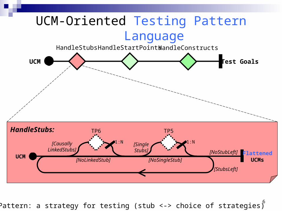
UCM Test Goals
HandleStubs HandleStartPoints HandleConstructs
HandleStubs:
[CausallyLinkedStubs]
UCMFlattened
UCMs
TP6
[SingleStubs]
TP5
1:N 1:N
[NoStubLeft]
[StubsLeft]
[NoLinkedStub] [NoSingleStub]
UCM-Oriented Testing Pattern Language
TP: Test Pattern: a strategy for testing (stub <-> choice of strategies)
7
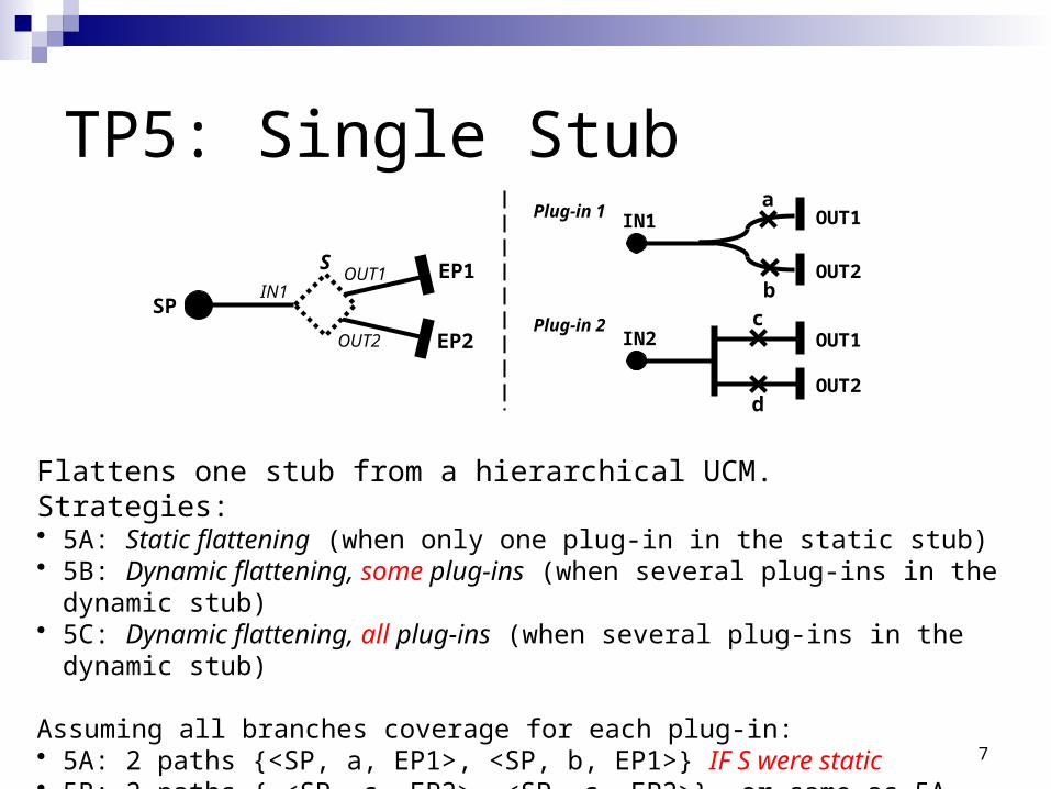
TP5: Single Stub
SP
SIN1
OUT1
OUT2
EP1
EP2 IN2 OUT1c
OUT2d
Plug-in 2
IN1 OUT1a
OUT2b
Plug-in 1
Flattens one stub from a hierarchical UCM.Strategies:• 5A: Static flattening (when only one plug-in in the static stub)• 5B: Dynamic flattening, some plug-ins (when several plug-ins in the dynamic stub)• 5C: Dynamic flattening, all plug-ins (when several plug-ins in the dynamic stub)
Assuming all branches coverage for each plug-in: • 5A: 2 paths {<SP, a, EP1>, <SP, b, EP1>} IF S were static• 5B: 2 paths { <SP, c, EP2>, <SP, c, EP2>} or same as 5A• 5C: 4 paths {<SP, a, EP1>, <SP, b, EP1>, <SP, c, EP2>, <SP, c, EP2>}
8
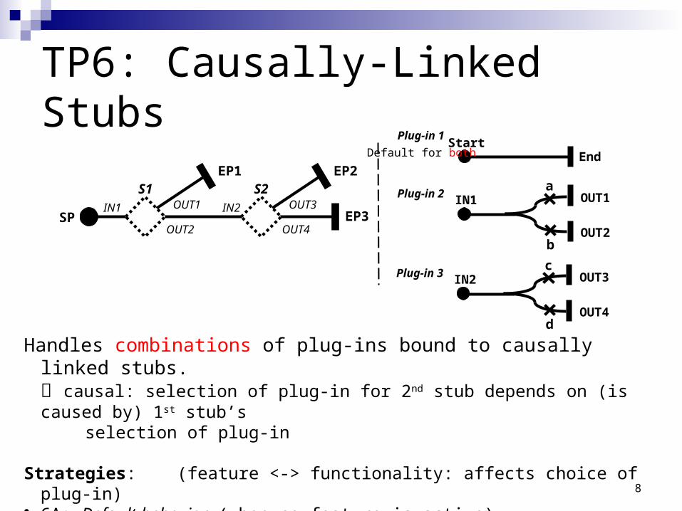
TP6: Causally-Linked Stubs
Handles combinations of plug-ins bound to causally linked stubs. causal: selection of plug-in for 2nd stub depends on (is caused by) 1st stub’s
selection of plug-in
Strategies: (feature <-> functionality: affects choice of plug-in)• 6A: Default behavior (when no feature is active)• 6B: Individual functionalities (when one feature is active at a time)• 6C: Functionality combinations (when several or all functionalities are active)
SP
S1IN1 OUT1
EP1
EP3IN1 OUT1
a
OUT2b
Plug-in 2
OUT2
S2IN2 OUT3
EP2
OUT4
IN2 OUT3c
OUT4d
Plug-in 3
StartEnd
Plug-in 1
Default for both
9
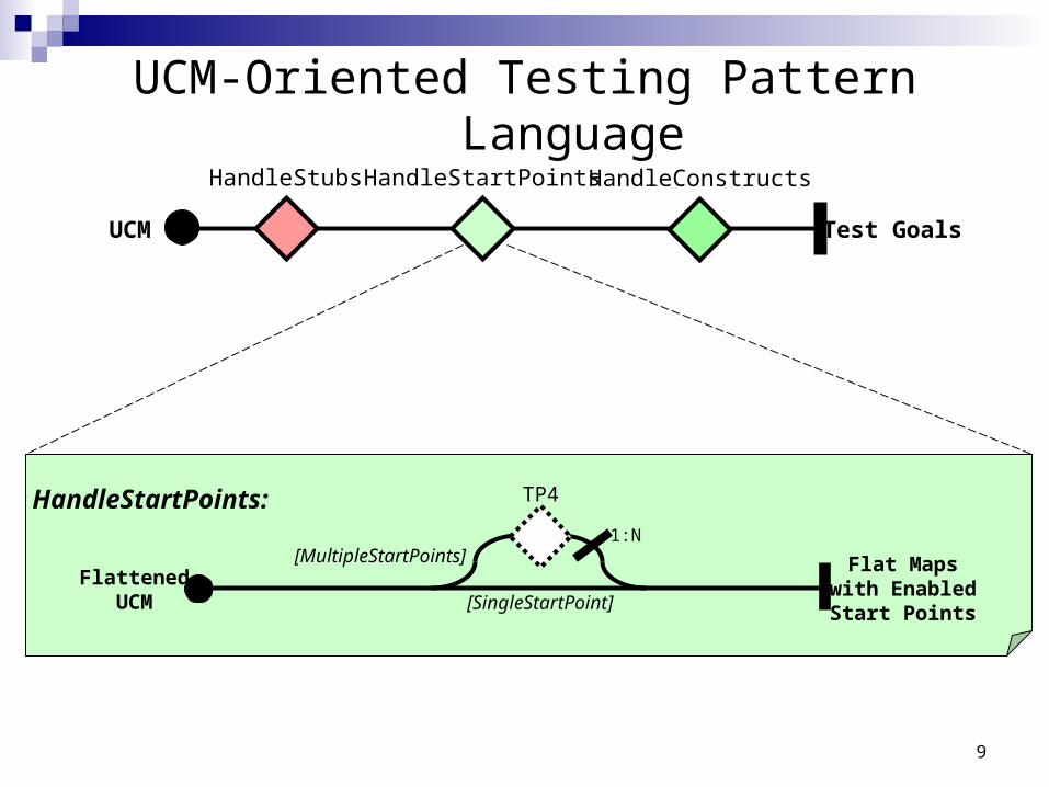
UCM Test Goals
HandleStubs HandleStartPoints HandleConstructs
HandleStartPoints:
[MultipleStartPoints]Flattened
UCM
Flat Mapswith EnabledStart Points
TP4
1:N
[SingleStartPoint]
UCM-Oriented Testing Pattern Language
10
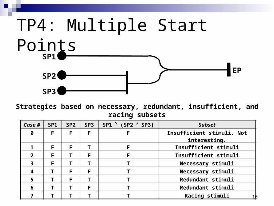
TP4: Multiple Start Points
Strategies based on necessary, redundant, insufficient, and racing subsets(8 strategies based on path sensitization)
SP3
EPSP2
SP1
Case # SP1 SP2 SP3 SP1 (SP2 SP3) Subset
0 F F F F Insufficient stimuli. Not interesting.
1 F F T F Insufficient stimuli
2 F T F F Insufficient stimuli
3 F T T T Necessary stimuli
4 T F F T Necessary stimuli
5 T F T T Redundant stimuli
6 T T F T Redundant stimuli
7 T T T T Racing stimuli
11
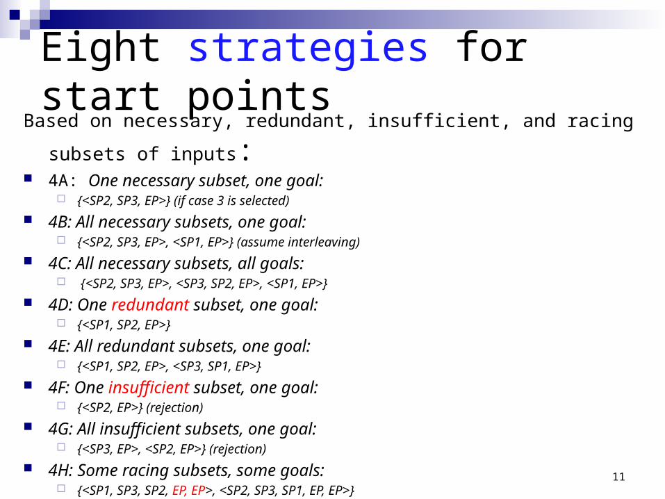
Eight strategies for start points Based on necessary, redundant, insufficient, and racing subsets of inputs: 4A: One necessary subset, one goal:
{<SP2, SP3, EP>} (if case 3 is selected)
4B: All necessary subsets, one goal: {<SP2, SP3, EP>, <SP1, EP>} (assume interleaving)
4C: All necessary subsets, all goals: {<SP2, SP3, EP>, <SP3, SP2, EP>, <SP1, EP>}
4D: One redundant subset, one goal: {<SP1, SP2, EP>}
4E: All redundant subsets, one goal: {<SP1, SP2, EP>, <SP3, SP1, EP>}
4F: One insufficient subset, one goal: {<SP2, EP>} (rejection)
4G: All insufficient subsets, one goal: {<SP3, EP>, <SP2, EP>} (rejection)
4H: Some racing subsets, some goals: {<SP1, SP3, SP2, EP, EP>, <SP2, SP3, SP1, EP, EP>}
12
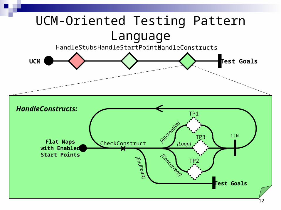
UCM-Oriented Testing Pattern Language
HandleConstructs:
Flat Mapswith EnabledStart Points
Test Goals
[Loop]
TP1
1:NTP3
TP2[A
ltern
ative
]
[Concurrent]
CheckConstruct[E
ndPoint]
UCM Test Goals
HandleStubs HandleStartPoints HandleConstructs
13
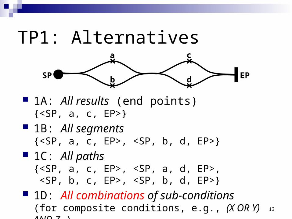
TP1: Alternativesa
SP EPb
c
d
1A: All results (end points){<SP, a, c, EP>}
1B: All segments{<SP, a, c, EP>, <SP, b, d, EP>}
1C: All paths{<SP, a, c, EP>, <SP, a, d, EP>, <SP, b, c, EP>, <SP, b, d, EP>}
1D: All combinations of sub-conditions (for composite conditions, e.g., (X OR Y) AND Z )
14
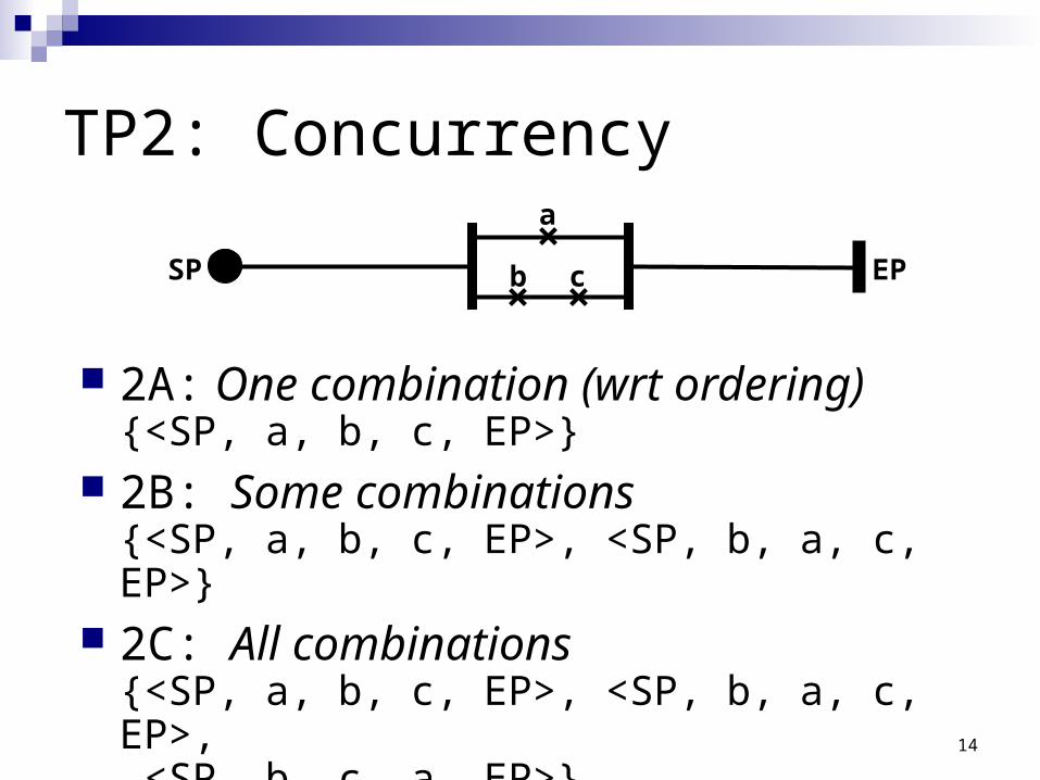
TP2: Concurrency
2A: One combination (wrt ordering){<SP, a, b, c, EP>}
2B: Some combinations{<SP, a, b, c, EP>, <SP, b, a, c, EP>}
2C: All combinations{<SP, a, b, c, EP>, <SP, b, a, c, EP>, <SP, b, c, a, EP>}
a
SP EPb c
15
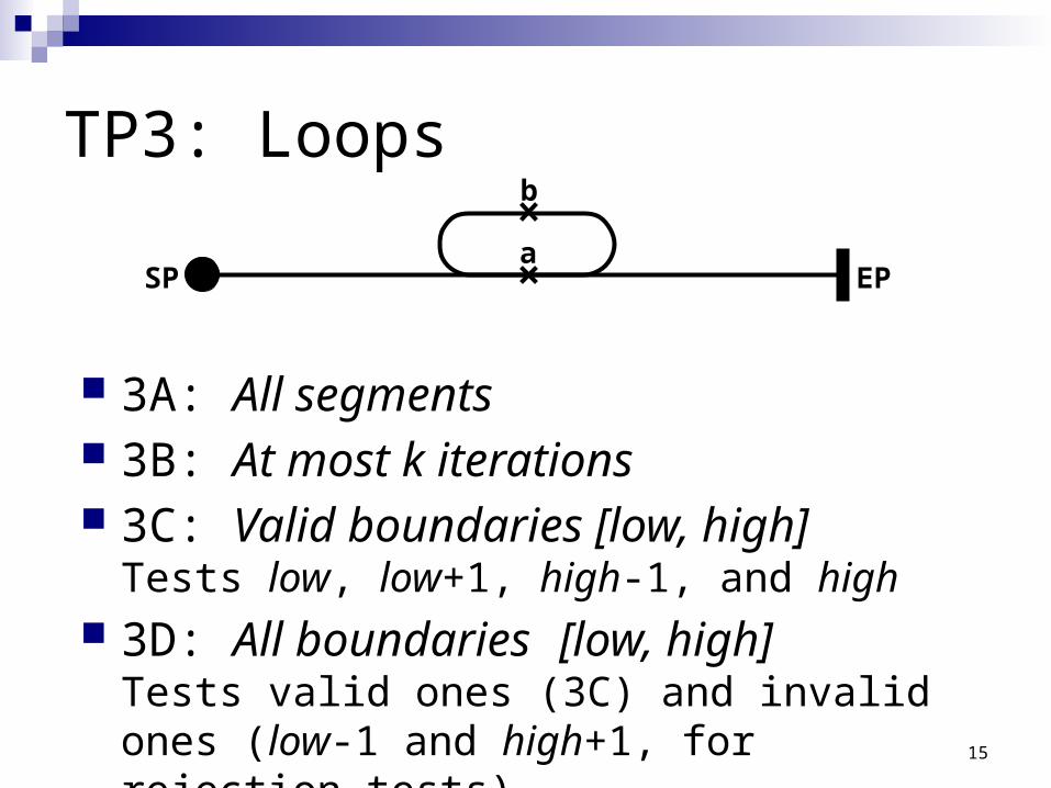
TP3: Loops
aSP EP
b
3A: All segments 3B: At most k iterations 3C: Valid boundaries [low, high]
Tests low, low+1, high-1, and high 3D: All boundaries [low, high]
Tests valid ones (3C) and invalid ones (low-1 and high+1, for rejection tests)
16
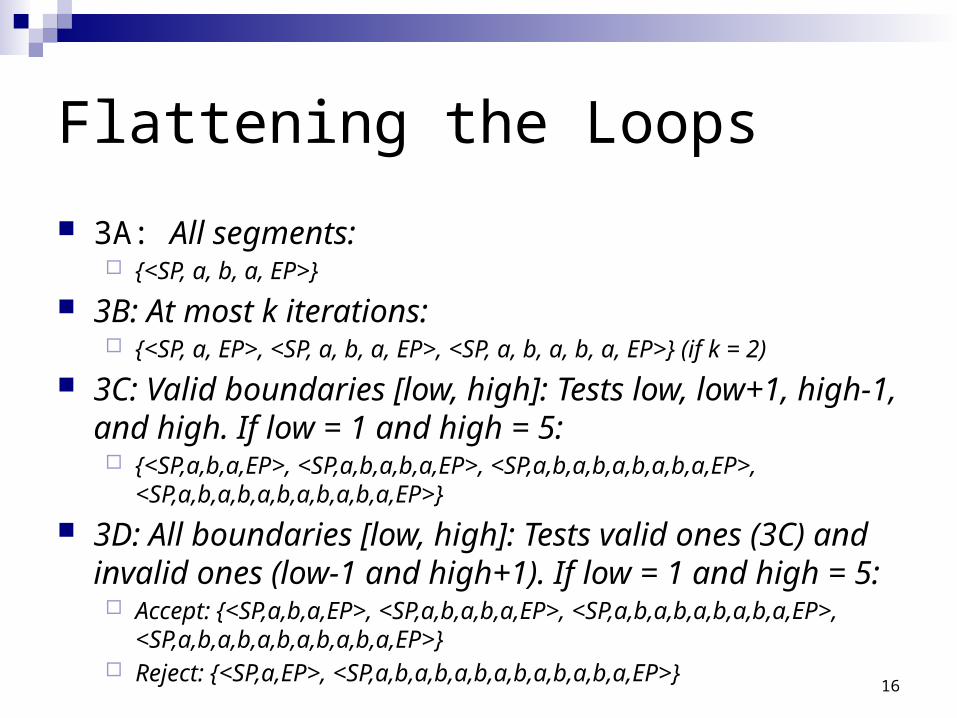
Flattening the Loops
3A: All segments: {<SP, a, b, a, EP>}
3B: At most k iterations: {<SP, a, EP>, <SP, a, b, a, EP>, <SP, a, b, a, b, a, EP>} (if k = 2)
3C: Valid boundaries [low, high]: Tests low, low+1, high-1, and high. If low = 1 and high = 5: {<SP,a,b,a,EP>, <SP,a,b,a,b,a,EP>, <SP,a,b,a,b,a,b,a,b,a,EP>,
<SP,a,b,a,b,a,b,a,b,a,b,a,EP>}
3D: All boundaries [low, high]: Tests valid ones (3C) and invalid ones (low-1 and high+1). If low = 1 and high = 5: Accept: {<SP,a,b,a,EP>, <SP,a,b,a,b,a,EP>, <SP,a,b,a,b,a,b,a,b,a,EP>,
<SP,a,b,a,b,a,b,a,b,a,b,a,EP>} Reject: {<SP,a,EP>, <SP,a,b,a,b,a,b,a,b,a,b,a,b,a,EP>}
17
Complementary Strategies
Strategies for value selectionEquivalence classes, boundary testing
These are typical approaches in traditional testing Strategies for rejection test cases
Forbidden scenariosTesting patterns Incomplete conditionsOff-by-one value
Meyer: Should we worry about invalid cases?

Appexdix 1: UCM Transformations
Delegating the testing of the whole model to some tool that can test the transformed model.
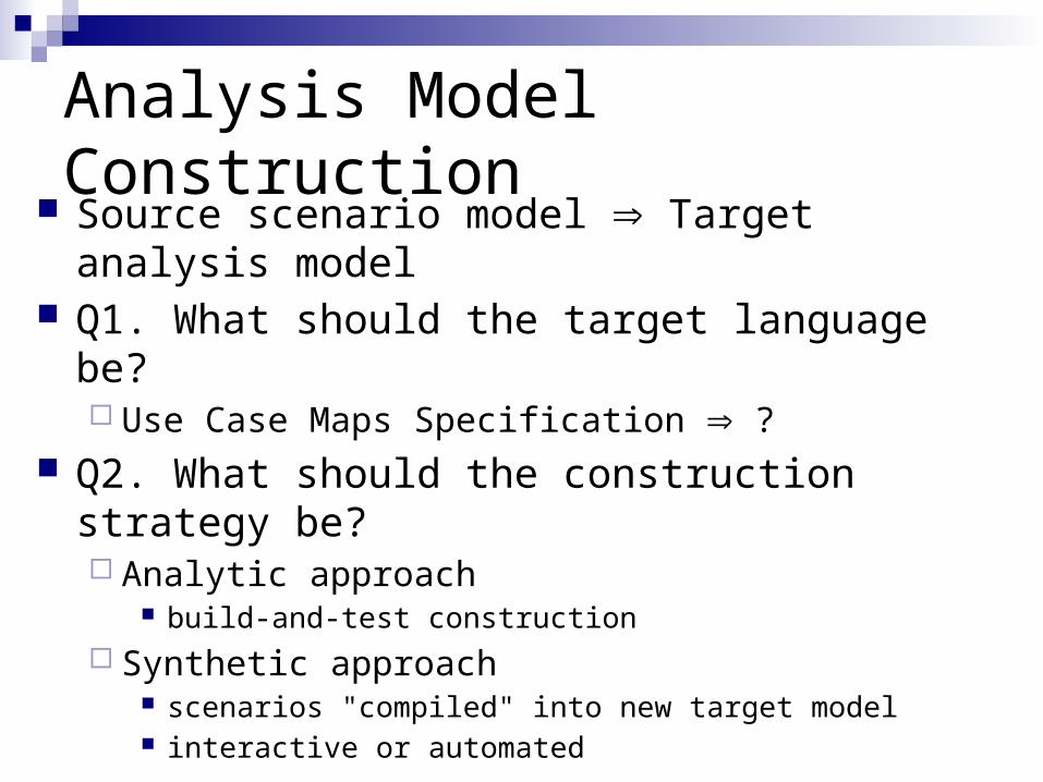
Analysis Model Construction Source scenario model Þ Target analysis model Q1. What should the target language be?
Use Case Maps Specification Þ ? Q2. What should the construction strategy be?
Analytic approach build-and-test construction
Synthetic approach scenarios "compiled" into new target model interactive or automated
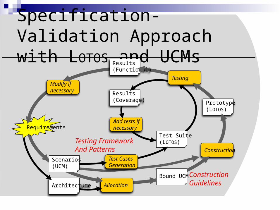
Specification-Validation Approach with LOTOS and UCMs
Results(Coverage)
Test Suite(LOTOS)
Add tests ifnecessary
Test CasesGeneration
Testing FrameworkAnd Patterns
Requirements
Bound UCM
Prototype(LOTOS)
Results(Functional)
Construction
Modify ifnecessary
Testing
Allocation
Scenarios(UCM)
Architecture
ConstructionGuidelines
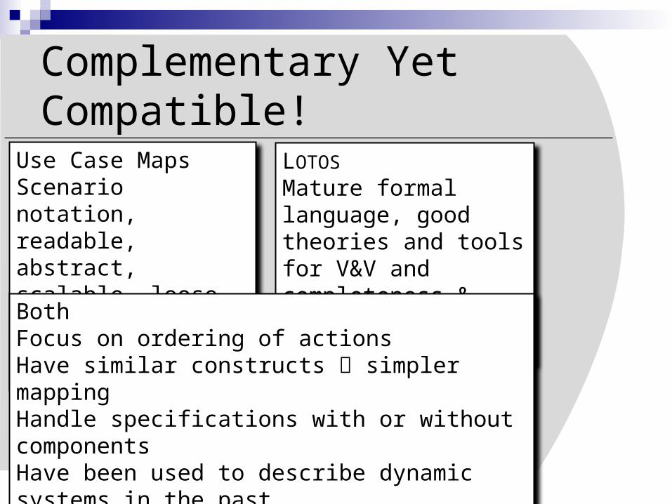
Complementary Yet Compatible!
Use Case MapsScenario notation, readable, abstract, scalable, loose, relatively effortless to learn
LOTOS
Mature formal language, good theories and tools for V&V and completeness &consistency checking.
BothFocus on ordering of actionsHave similar constructs simpler mappingHandle specifications with or without componentsHave been used to describe dynamic systems in the pastHave been used to detect feature interactions in the past
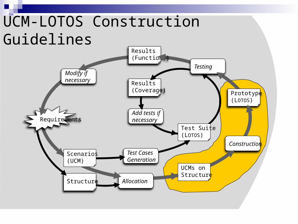
Requirements
Scenarios(UCM)
Structure
UCMs onStructure
Prototype(LOTOS)
Results(Functions)
Results(Coverage)
Test Suite(LOTOS)
Add tests ifnecessary
Test CasesGeneration
Construction
Modify ifnecessary
Testing
Allocation
UCM-LOTOS Construction Guidelines
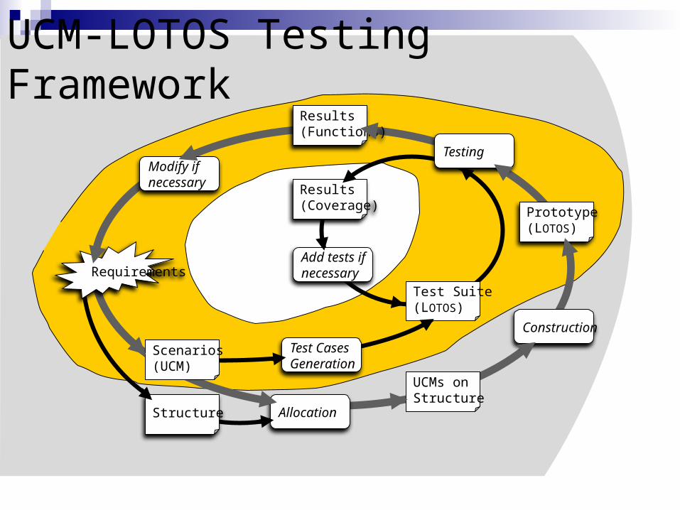
UCM-LOTOS Testing Framework
Requirements
Scenarios(UCM)
Structure
UCMs onStructure
Prototype(LOTOS)
Results(Functions)
Results(Coverage)
Test Suite(LOTOS)
Add tests ifnecessary
Test CasesGeneration
Construction
Modify ifnecessary
Testing
Allocation
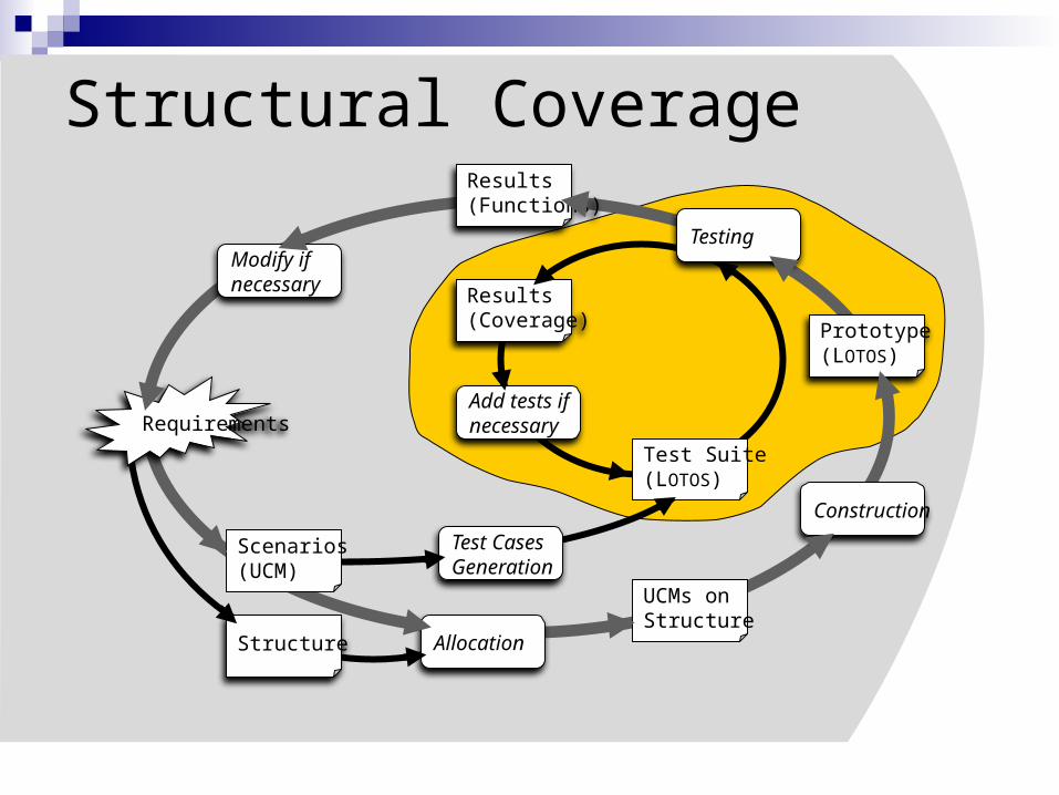
Structural Coverage
Requirements
Scenarios(UCM)
Structure
UCMs onStructure
Prototype(LOTOS)
Results(Functions)
Results(Coverage)
Test Suite(LOTOS)
Add tests ifnecessary
Test CasesGeneration
Construction
Modify ifnecessary
Testing
Allocation
25
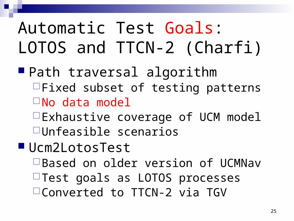
Automatic Test Goals:LOTOS and TTCN-2 (Charfi) Path traversal algorithm
Fixed subset of testing patternsNo data modelExhaustive coverage of UCM modelUnfeasible scenarios
Ucm2LotosTest Based on older version of UCMNavTest goals as LOTOS processesConverted to TTCN-2 via TGV
26
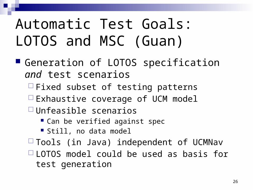
Automatic Test Goals:LOTOS and MSC (Guan) Generation of LOTOS specification and test
scenarios Fixed subset of testing patterns Exhaustive coverage of UCM model Unfeasible scenarios
Can be verified against spec Still, no data model
Tools (in Java) independent of UCMNav LOTOS model could be used as basis for test
generation
27
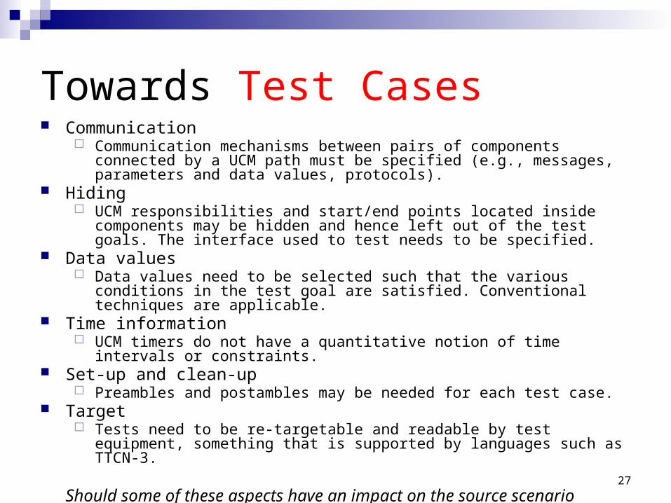
Towards Test Cases Communication
Communication mechanisms between pairs of components connected by a UCM path must be specified (e.g., messages, parameters and data values, protocols).
Hiding UCM responsibilities and start/end points located inside components may be
hidden and hence left out of the test goals. The interface used to test needs to be specified.
Data values Data values need to be selected such that the various conditions in the test goal
are satisfied. Conventional techniques are applicable. Time information
UCM timers do not have a quantitative notion of time intervals or constraints. Set-up and clean-up
Preambles and postambles may be needed for each test case. Target
Tests need to be re-targetable and readable by test equipment, something that is supported by languages such as TTCN-3.
Should some of these aspects have an impact on the source scenario language?
28
Tools UCMNav 2.2
http://www.usecasemaps.org/tools/ucmnav/
UCMExporterhttp://ucmexporter.sourceforge.net/
UCM2LOTOSAvailable from Daniel Amyot upon request
29
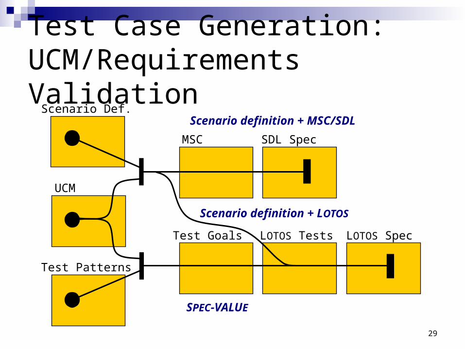
Test Case Generation:UCM/Requirements Validation
Scenario Def.
MSC SDL Spec
UCM
Test Goals
Test Patterns
LOTOS Tests LOTOS Spec
SPEC-VALUE
Scenario definition + MSC/SDL
Scenario definition + LOTOS
30
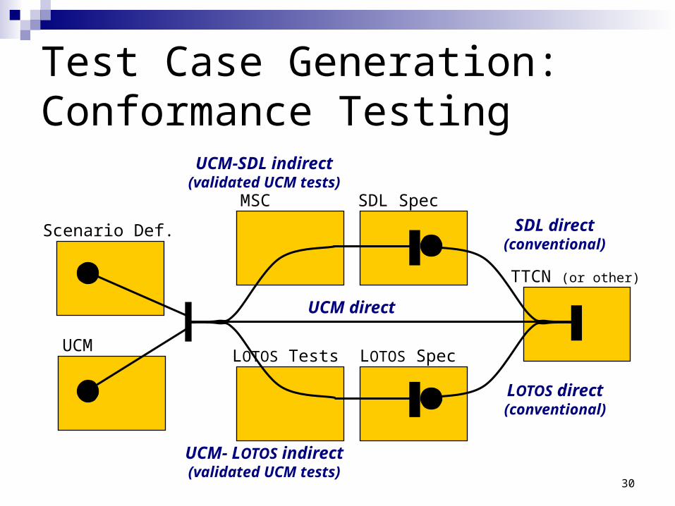
Test Case Generation:Conformance Testing
UCM direct
SDL direct(conventional)
SDL Spec
TTCN (or other)
LOTOS Spec
Scenario Def.
UCM
MSC
LOTOS Tests
LOTOS direct(conventional)
UCM-SDL indirect(validated UCM tests)
UCM- LOTOS indirect(validated UCM tests)
Appendix 2: Why UCMs?
Requirements Engineering Issues Early focus on low-level abstractions Requirements and high-level decisions
buried in the details Evolution of functionalities difficult to
handle (feature interactions, V&V, adaptability to legacy architectures...)
Delay introduction of new services
Software Engineering Issues
Requirements/analysis models need to support new types of dynamic systemsRun-time modification of system structureRun-time modification of behaviour
Need to go from a requirements/analysis model to design models in a seamless way
We propose Use Case Maps (UCMs)!
Use Case Maps (UCMs)
The Use Case Maps notation allows illustrating a scenario path relative to optional components involved in the scenario (gray box view of system)
UCMs are a scenario-based software engineering technique for describing causal relationships between responsibilities of one or more use cases
UCMs show related use cases in a map-like diagram
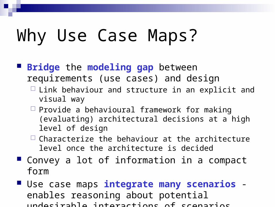
Why Use Case Maps?
Bridge the modeling gap between requirements (use cases) and design Link behaviour and structure in an explicit and visual way Provide a behavioural framework for making (evaluating)
architectural decisions at a high level of design Characterize the behaviour at the architecture level once the
architecture is decided Convey a lot of information in a compact form Use case maps integrate many scenarios - enables
reasoning about potential undesirable interactions of scenarios
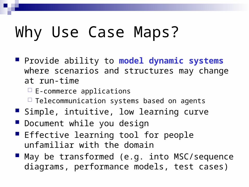
Why Use Case Maps?
Provide ability to model dynamic systems where scenarios and structures may change at run-time E-commerce applications Telecommunication systems based on agents
Simple, intuitive, low learning curve Document while you design Effective learning tool for people unfamiliar with the
domain May be transformed (e.g. into MSC/sequence diagrams,
performance models, test cases)