Embed Size (px)
Citation preview
Amirkabir Journal of Mechanical Engineering
Amirkabir J. Mech. Eng., 50(3) (2018) 181-184DOI: 10.22060/mej.2017.12721.5408
Buckling Analysis on Cylindrical Shell with Longitudinal and Circumferential Welds
P. Seyedmonir*, M. Shakeri, I. Sattarifar
Mechanical Engineering Department, Amirkabir University of Technology, Tehran, Iran
ABSTRACT: Near to a century, buckling on shells especially on cylindrical shells under axial compression is Bing survey. Buckling of shells carried out less than classical load and many years it was a puzzle for mechanical scientists and researchers. Exactly estimate of buckling critical load for optimum design and safety in mechanical structures like as pressure vessel, rockets, airplane body is very important because buckling is catastrophic. Imperfections consist of geometric defects, variation in thickness, material properties uniformity and boundary condition can be decrease buckling critical load. Geometric imperfections like as out of roundness and ovality is the result of manufacturing process. Plate roll forming and welding is a method for shell fabrication and unavoidable and welds are source of imperfections. Three cylindrical shells fabricated by roll forming and welding. Imperfections of shells measured by 3D scan camera and then tested under axial compression with press. Results show welds have created imperfections especially around the weld line and decrease critical buckling load. Shell with circumferential weld buckled lower than buckling load of shells with only longitudinal weld line. Measured imperfections introduce to nodes in finite element mesh modeling directly and results of finite element analysis compared to experimental load – displacement curves until the effects of welds on critical load compare to perfect shell buckling load.
Review History:
Received: 4 April 2016Revised: 30 May 2017Accepted: 2 July 2017Available Online: 24 July 2017
Keywords:
BucklingImperfectionsCylindrical shellAxial pressureWeld
181
1- IntroductionAxially compressed welded steel cylindrical shells have a wide application in engineering. Axial elastic or plastic buckling is the key point in their design .Many researchers have investigated the effect of different initial geometric imperfections on elastic or plastic buckling of cylindrical shells (Donnel [1], 1934; Koiter [2], 1963; Arbocz [3], 1990; Almorth, Bo and Brush [3], 1975). It was found that the extent to which the buckling critical load is decreased depends on the shape and the amplitude of the initial geometric imperfections, and the worst initial geometric imperfection to a newly built cylindrical shell structure depends on the manufacturing process. Welded steel cylindrical shells in engineering are usually constructed by many curved steel panels. Circumferential welds rather than longitudinal welds between these curved panels are regarded as one of the worst initial geometric imperfections to axial elastic or plastic buckling of welded steel cylindrical shells. In this paper, the effect of circumferential and longitudinal welds on the axial buckling of welded steel cylindrical shells is studied experimentally and numerically. Three types of cylindrical shell specimens with the same ratio of radius to wall thickness and material but different weld direction are manufactured. Their initial geometric imperfections and experimental axial buckling critical loads are obtained through a self-made buckling platform. Nonlinear buckling analysis is carried out through finite element analysis. The relationship between weld direction and buckling critical load is explored.
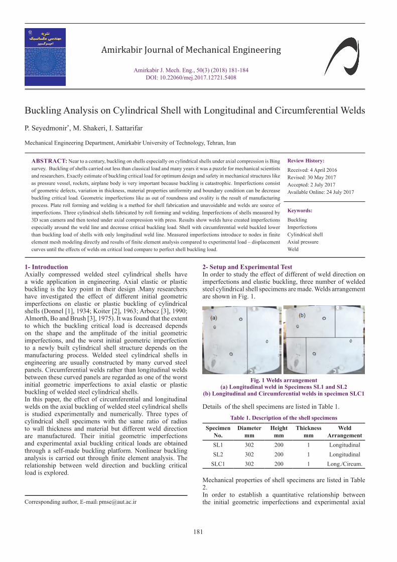
2- Setup and Experimental TestIn order to study the effect of different of weld direction on imperfections and elastic buckling, three number of welded steel cylindrical shell specimens are made. Welds arrangement are shown in Fig. 1.
Details of the shell specimens are listed in Table 1.
Mechanical properties of shell specimens are listed in Table 2.In order to establish a quantitative relationship between the initial geometric imperfections and experimental axial Corresponding author, E-mail: [email protected]
Fig. 1 Welds arrangement(a) Longitudinal weld in Specimens SL1 and SL2
(b) Longitudinal and Circumferential welds in specimen SLC1
Specimen No.
Diameter mm
Height mm
Thickness mm
Weld Arrangement
SL1 302 200 1 LongitudinalSL2 302 200 1 Longitudinal
SLC1 302 200 1 Long./Circum.
Table 1. Description of the shell specimens

P. Seyedmonir et al., Amirkabir J. Mech. Eng., 50(3) (2018) 181-184, DOI: 10.22060/mej.2017.12721.5408
182
buckling critical load and to construct a finite element model that incorporates the real initial geometric imperfections of the shell specimens, imperfections are scanned by 3D Camera as shown in Fig.2, CATIA software is used to assign the measured data to the nodes of the finite element model.
The statistical information for the measured imperfections is shown in Table 3.
Buckling experimental platform with axial loading function by displacement control is made. The photo of the experimental platform is shown in Fig.3.
3- FEM AnalysisThe large commercial FEM software ABAQUS is used for the finite element analysis. The element type S4R5 with 5x5 dimensions is chosen [1, 2]. Both geometric and material nonlinearity are included. The material constitutive law is the true stress-strain relationship based on the tensile test
data. Mises yield criteria are used. The Static Riks method is adopted to calculate the buckling critical load.
4- Results and DiscussionExperimental buckling deformation of the specimens is shown in Fig.4. The experimental relationship between axial load and axial displacement of all specimens is shown in Fig. 5.
Contours plots of buckling deformation of all specimens obtained by FE analysis are shown in Fig. 6.
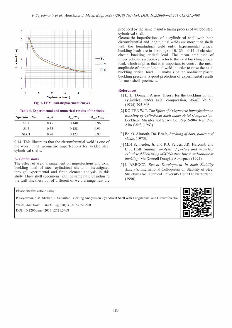
Fig. 7 shows a finite element analysis results of axial loads corresponding to axial displacement.The classical elastic buckling critical load is calculated as follows [3, 4]:
(1)3 10.605 0.605 189 10 759.5MPa150.5CL
hER
σ = = × × × =
Table 4 shows that the dimensionless mean amplitu-de of imperfections w0 /t is between 0.45 and 0.70 (the maximum value is adopted for the specimen with longitudinal and circumferential welds), and the dimensionless experimental axial buckling critical load σexp /σCL is between 0.123 and
Material Yield Stress MPa
Max. Stress MPa Strain
ST12 221.6 298 38.8%
Table 2. Mechanical properties of shell specimens
Fig. 2. 3D scanner camera
Specimen No.
Maximum mm
Minimum mm
Average mm
STD. Deviation
mmSL1 0.83 -1.55 0.41 0.495SL2 1.038 -2.66 0.56 0.628
SLC1 2.29 -2.37 0.63 0.739
Table 3. Statistical information of shells imperfections
Fig. 3. Experimental platform
Fig. 4. Buckling deformation of the shell specimens(a) SL1; (b) SL2; (c) SLC1
Fig. 5. Experimental load-displacement curves
Fig. 6. Buckling deformation contours(a) SL1; (b) SL2; (c) SLC1
P. Seyedmonir et al., Amirkabir J. Mech. Eng., 50(3) (2018) 181-184, DOI: 10.22060/mej.2017.12721.5408
183
0.14. This illustrates that the circumferential weld is one of the worst initial geometric imperfections for welded steel cylindrical shells.
5- ConclusionsThe effect of weld arrangement on imperfections and axial buckling load of steel cylindrical shells is investigated through experimental and finite element analysis in this study. Three shell specimens with the same ratio of radius to the wall thickness but of different of weld arrangement are
produced by the same manufacturing process of welded steel cylindrical shell. Geometric imperfections of a cylindrical shell with both circumferential and longitudinal welds are more than shells with the longitudinal weld only. Experimental critical buckling loads are in the range of 0.123 – 0.14 of classical elastic buckling critical load. The mean amplitude of imperfections is a decisive factor to the axial buckling critical load, which implies that it is important to control the mean amplitude of circumferential weld in order to raise the axial buckling critical load. FE analysis of the nonlinear plastic buckling presents a good prediction of experimental results for most shell specimens.
References[1] L. H. Donnell, A new Theory for the buckling of thin
cylindrical under axial compression, ASME Vol.56, (1934) 795-806.
[2] KOITER W. T. The Effect of Axisymetric Imperfection on Buckling of Cylindrical Shell under Axial Compression, Lockheed Missiles and Space Co. Rep. 6-90-63-86 Palo Alto Calif, (1963).
[3] Bo. O. Almroth, Do. Brush, Buckling of bars, plates and shells, (1975).
[4] M.H Schneider, Jr. and R.J. Feldes, J.R. Halcomb and C.C. Hoff. Stability analysis of perfect and imperfect cylindrical Shell using MSC/Nastran linear and nonlinear buckling. Mc Donnell Douglas Aerospace (1994).
[5] J. ARBOCZ. Recent Development In Shell Stability Analysis. International Colloquium on Stability of Steel Structure also Technical University Delft The Netherland, (1990).
Please cite this article using:
P. Seyedmonir, M. Shakeri, I. Sattarifar, Buckling Analysis on Cylindrical Shell with Longitudinal and Circumferential
Welds, Amirkabir J. Mech. Eng., 50(3) (2018) 551-560.DOI: 10.22060/mej.2017.12721.5408
Fig. 7. FEM load-displacement curves
Specimen No. w0 /t σexp /σCL σexp /σFEM
SL1 0.45 0.140 0.96SL2 0.55 0.128 0.91
SLC1 0.70 0.123 0.97
Table 4. Experimental and numerical results of the shells