Embed Size (px)
Citation preview
UC I : Na t u r a l S c i e n c e s Un i t 2
Tech Report 2: Electrical Existing Conditions + Building Load SummaryNovember 4, 2008
I r v i n e , C a l i f o r n i a
Grant W. Kight l ingerLighting/Electrical OptionAdvisor: Prof. Ted Dannerth
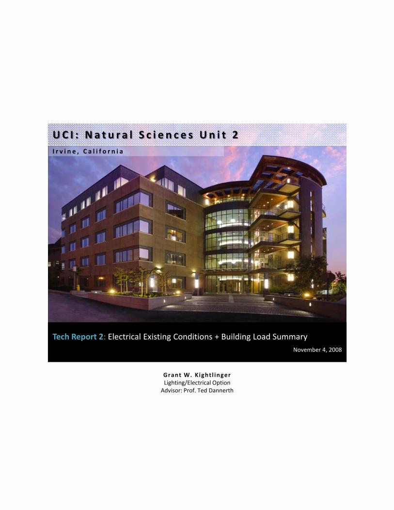
C o n t e n t s
Executive Summary ................................................................................................................................................................. 1
Single-Line Diagram Drawing List ............................................................................................................................................ 2
Single-Line Diagram ................................................................................................................................................................ 3
Feeder Schedule ...................................................................................................................................................................... 4
Summary Description of Distribution System ......................................................................................................................... 8
Utility Company Information .................................................................................................................................................. 8
Service Entrance ...................................................................................................................................................................... 8
Voltage Systems ...................................................................................................................................................................... 8
Emergency Power System ....................................................................................................................................................... 9
Locations of Switchgear ........................................................................................................................................................ 10
Over-current Devices ............................................................................................................................................................ 13
Transformers ......................................................................................................................................................................... 14
Special Equipment................................................................................................................................................................. 14
Lighting Loads ....................................................................................................................................................................... 15
Mechanical and Other Loads ................................................................................................................................................ 16
Service Entrance Size ............................................................................................................................................................ 17
Environmental Stewardship Design ...................................................................................................................................... 18
Design Issues ......................................................................................................................................................................... 18
Communication Systems ....................................................................................................................................................... 18
Appendix ............................................................................................................................................................................... 19
HID Lamp / Ballast Specifications
Single-Line Diagram
Existing Riser Diagrams
UCI Natural Sciences Unit 2 | Irvine, California Technical Report 2 - Kightlinger
P a g e | 1
Executive Summary
The following is an analysis of the existing electrical conditions for Natural Sciences Unit 2, located on the campus of the
University of California at Irvine. This five-story academic building is divided into two wings containing science
laboratories and graduate student/faculty offices. A recently completed addition to the modern UCI campus, the
building’s electrical system is designed to be simple and efficient, while still allowing for future growth.
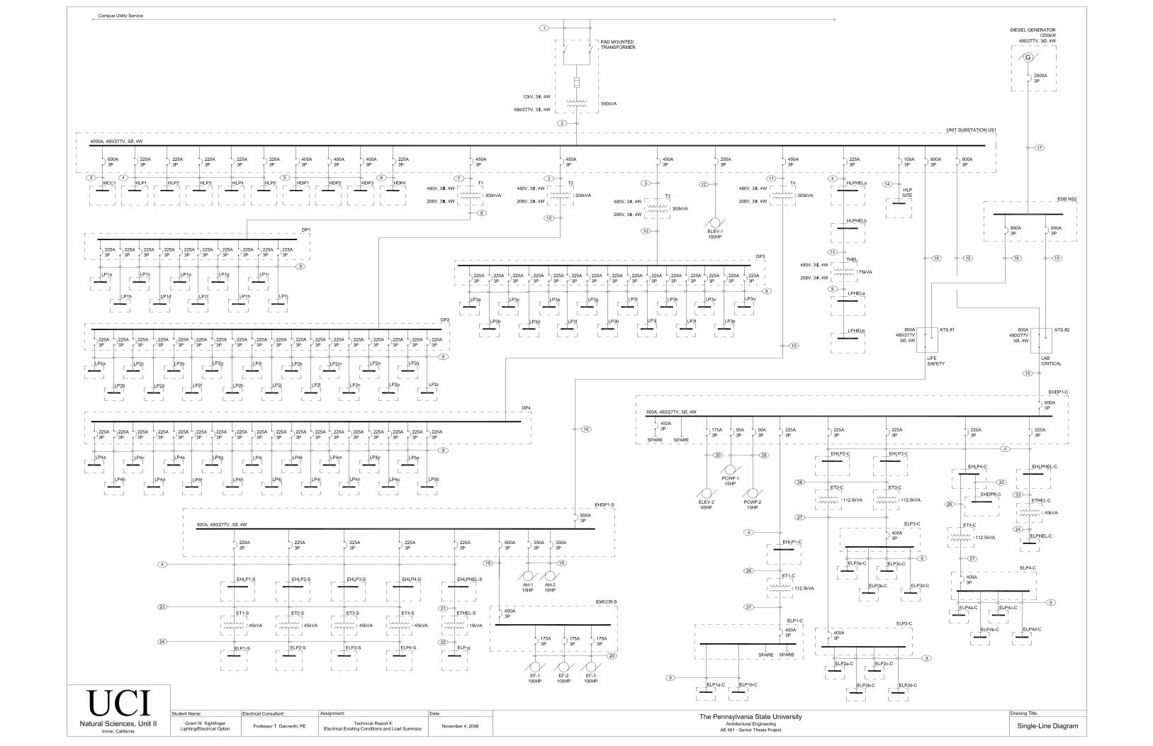
Contained in this report is a single-line diagram, illustrating the existing distribution of the entire electrical system for
the building. Feeder sizes and equipment specifications are also included in the body of the report, including all
emergency generation and distribution equipment. A detailed list of electrical loads has been compiled, and several
methods for calculating service entrance size have been illustrated. Other important design issues such as
environmental stewardship, communication systems, and special design complications have been addressed.
UCI Natural Sciences Unit 2 | Irvine, California Technical Report 2 - Kightlinger
P a g e | 2
Single-Line Diagram Drawing List
The following drawings were utilized to construct the single-line diagram for this building.
Drawing No. Drawing Title
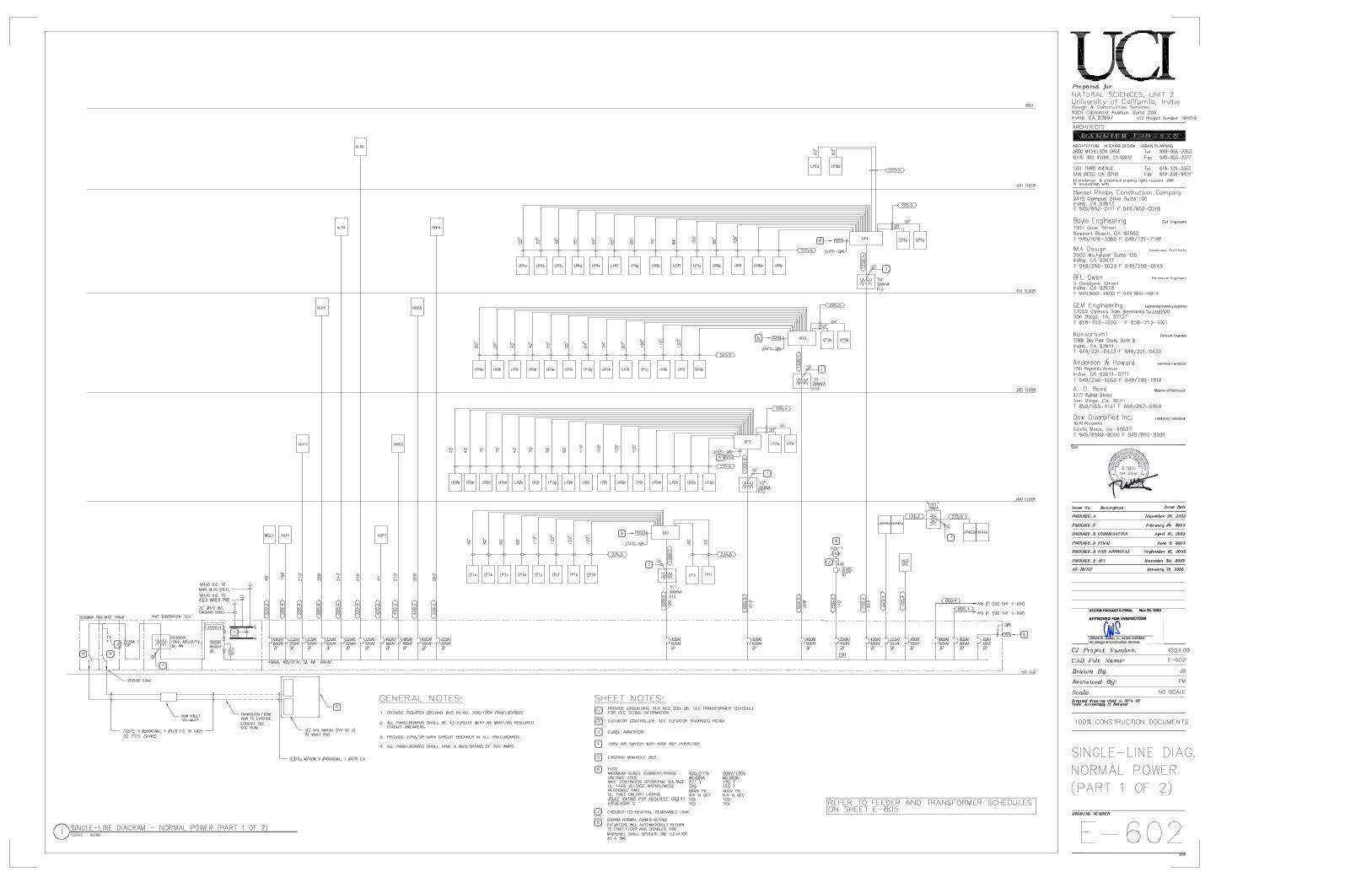
E-602 Single-Line Diagram, Normal Power (Part 1 of 2)
E-603 Single-Line Diagram, Normal Power (Part 2 of 2)
E-604 Electrical Single-Line, Emergency
E-605 Feeder & Transformer Schedules and Load Summary
UCI Natural Sciences Unit 2 | Irvine, California Technical Report 2 - Kightlinger
P a g e | 4
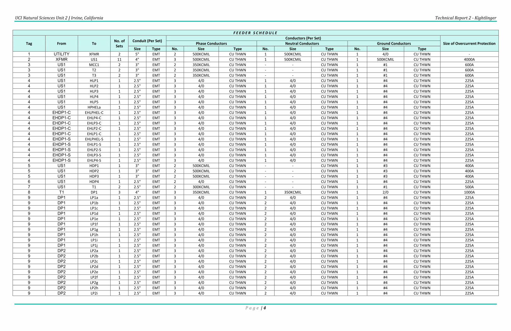
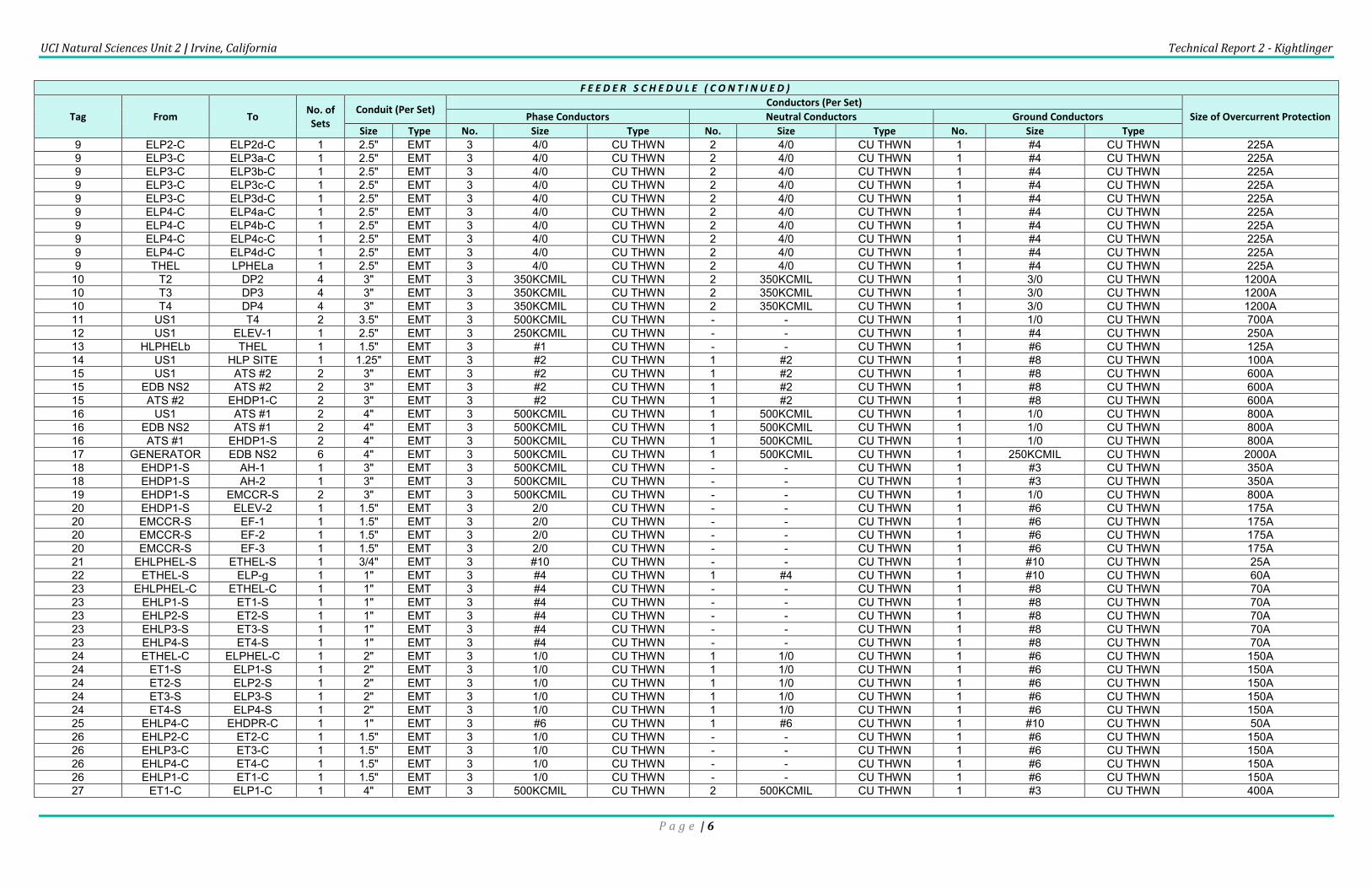
F E E D E R S C H E D U L E
Tag From To No. of Sets
Conduit (Per Set) Conductors (Per Set)
Size of Overcurrent Protection Phase Conductors Neutral Conductors Ground Conductors
Size Type No. Size Type No. Size Type No. Size Type
1 UTILITY XFMR 2 5" EMT 2 500KCMIL CU THWN 1 500KCMIL CU THWN 1 4/0 CU THWN -
2 XFMR US1 11 4" EMT 3 500KCMIL CU THWN 1 500KCMIL CU THWN 1 500KCMIL CU THWN 4000A
3 US1 MCC1 2 3" EMT 2 350KCMIL CU THWN - - CU THWN 1 #1 CU THWN 600A
3 US1 T2 2 3" EMT 2 350KCMIL CU THWN - - CU THWN 1 #1 CU THWN 600A
3 US1 T3 2 3" EMT 2 350KCMIL CU THWN - - CU THWN 1 #1 CU THWN 600A
4 US1 HLP1 1 2.5" EMT 3 4/0 CU THWN 1 4/0 CU THWN 1 #4 CU THWN 225A
4 US1 HLP2 1 2.5" EMT 3 4/0 CU THWN 1 4/0 CU THWN 1 #4 CU THWN 225A
4 US1 HLP3 1 2.5" EMT 3 4/0 CU THWN 1 4/0 CU THWN 1 #4 CU THWN 225A
4 US1 HLP4 1 2.5" EMT 3 4/0 CU THWN 1 4/0 CU THWN 1 #4 CU THWN 225A
4 US1 HLP5 1 2.5" EMT 3 4/0 CU THWN 1 4/0 CU THWN 1 #4 CU THWN 225A
4 US1 HPHELa 1 2.5" EMT 3 4/0 CU THWN 1 4/0 CU THWN 1 #4 CU THWN 225A
4 EHDP1-C EHLPHEL-C 1 2.5" EMT 3 4/0 CU THWN 1 4/0 CU THWN 1 #4 CU THWN 225A
4 EHDP1-C EHLP4-C 1 2.5" EMT 3 4/0 CU THWN 1 4/0 CU THWN 1 #4 CU THWN 225A
4 EHDP1-C EHLP3-C 1 2.5" EMT 3 4/0 CU THWN 1 4/0 CU THWN 1 #4 CU THWN 225A
4 EHDP1-C EHLP2-C 1 2.5" EMT 3 4/0 CU THWN 1 4/0 CU THWN 1 #4 CU THWN 225A
4 EHDP1-C EHLP1-C 1 2.5" EMT 3 4/0 CU THWN 1 4/0 CU THWN 1 #4 CU THWN 225A
4 EHDP1-S EHLPHEL-S 1 2.5" EMT 3 4/0 CU THWN 1 4/0 CU THWN 1 #4 CU THWN 225A
4 EHDP1-S EHLP1-S 1 2.5" EMT 3 4/0 CU THWN 1 4/0 CU THWN 1 #4 CU THWN 225A
4 EHDP1-S EHLP2-S 1 2.5" EMT 3 4/0 CU THWN 1 4/0 CU THWN 1 #4 CU THWN 225A
4 EHDP1-S EHLP3-S 1 2.5" EMT 3 4/0 CU THWN 1 4/0 CU THWN 1 #4 CU THWN 225A
4 EHDP1-S EHLP4-S 1 2.5" EMT 3 4/0 CU THWN 1 4/0 CU THWN 1 #4 CU THWN 225A
5 US1 HDP1 1 3" EMT 2 500KCMIL CU THWN - - CU THWN 1 #3 CU THWN 400A
5 US1 HDP2 1 3" EMT 2 500KCMIL CU THWN - - CU THWN 1 #3 CU THWN 400A
5 US1 HDP3 1 3" EMT 2 500KCMIL CU THWN - - CU THWN 1 #3 CU THWN 400A
6 US1 HDP4 1 2.5" EMT 2 4/0 CU THWN - - CU THWN 1 #4 CU THWN 225A
7 US1 T1 2 2.5" EMT 2 300KCMIL CU THWN - - CU THWN 1 #1 CU THWN 500A
8 T1 DP1 3 4" EMT 3 350KCMIL CU THWN 1 350KCMIL CU THWN 1 2/0 CU THWN 1000A
9 DP1 LP1a 1 2.5" EMT 3 4/0 CU THWN 2 4/0 CU THWN 1 #4 CU THWN 225A
9 DP1 LP1b 1 2.5" EMT 3 4/0 CU THWN 2 4/0 CU THWN 1 #4 CU THWN 225A
9 DP1 LP1c 1 2.5" EMT 3 4/0 CU THWN 2 4/0 CU THWN 1 #4 CU THWN 225A
9 DP1 LP1d 1 2.5" EMT 3 4/0 CU THWN 2 4/0 CU THWN 1 #4 CU THWN 225A
9 DP1 LP1e 1 2.5" EMT 3 4/0 CU THWN 2 4/0 CU THWN 1 #4 CU THWN 225A
9 DP1 LP1f 1 2.5" EMT 3 4/0 CU THWN 2 4/0 CU THWN 1 #4 CU THWN 225A
9 DP1 LP1g 1 2.5" EMT 3 4/0 CU THWN 2 4/0 CU THWN 1 #4 CU THWN 225A
9 DP1 LP1h 1 2.5" EMT 3 4/0 CU THWN 2 4/0 CU THWN 1 #4 CU THWN 225A
9 DP1 LP1i 1 2.5" EMT 3 4/0 CU THWN 2 4/0 CU THWN 1 #4 CU THWN 225A
9 DP1 LP1j 1 2.5" EMT 3 4/0 CU THWN 2 4/0 CU THWN 1 #4 CU THWN 225A
9 DP2 LP2a 1 2.5" EMT 3 4/0 CU THWN 2 4/0 CU THWN 1 #4 CU THWN 225A
9 DP2 LP2b 1 2.5" EMT 3 4/0 CU THWN 2 4/0 CU THWN 1 #4 CU THWN 225A
9 DP2 LP2c 1 2.5" EMT 3 4/0 CU THWN 2 4/0 CU THWN 1 #4 CU THWN 225A
9 DP2 LP2d 1 2.5" EMT 3 4/0 CU THWN 2 4/0 CU THWN 1 #4 CU THWN 225A
9 DP2 LP2e 1 2.5" EMT 3 4/0 CU THWN 2 4/0 CU THWN 1 #4 CU THWN 225A
9 DP2 LP2f 1 2.5" EMT 3 4/0 CU THWN 2 4/0 CU THWN 1 #4 CU THWN 225A
9 DP2 LP2g 1 2.5" EMT 3 4/0 CU THWN 2 4/0 CU THWN 1 #4 CU THWN 225A
9 DP2 LP2h 1 2.5" EMT 3 4/0 CU THWN 2 4/0 CU THWN 1 #4 CU THWN 225A
9 DP2 LP2i 1 2.5" EMT 3 4/0 CU THWN 2 4/0 CU THWN 1 #4 CU THWN 225A

UCI Natural Sciences Unit 2 | Irvine, California Technical Report 2 - Kightlinger
P a g e | 5
F E E D E R S C H E D U L E ( C O N T I N U E D )
Tag From To No. of Sets
Conduit (Per Set) Conductors (Per Set)
Size of Overcurrent Protection Phase Conductors Neutral Conductors Ground Conductors
Size Type No. Size Type No. Size Type No. Size Type
9 DP2 LP2j 1 2.5" EMT 3 4/0 CU THWN 2 4/0 CU THWN 1 #4 CU THWN 225A
9 DP2 LP2k 1 2.5" EMT 3 4/0 CU THWN 2 4/0 CU THWN 1 #4 CU THWN 225A
9 DP2 LP2l 1 2.5" EMT 3 4/0 CU THWN 2 4/0 CU THWN 1 #4 CU THWN 225A
9 DP2 LP2m 1 2.5" EMT 3 4/0 CU THWN 2 4/0 CU THWN 1 #4 CU THWN 225A
9 DP2 LP2n 1 2.5" EMT 3 4/0 CU THWN 2 4/0 CU THWN 1 #4 CU THWN 225A
9 DP2 LP2o 1 2.5" EMT 3 4/0 CU THWN 2 4/0 CU THWN 1 #4 CU THWN 225A
9 DP2 LP2p 1 2.5" EMT 3 4/0 CU THWN 2 4/0 CU THWN 1 #4 CU THWN 225A
9 DP2 LP2q 1 2.5" EMT 3 4/0 CU THWN 2 4/0 CU THWN 1 #4 CU THWN 225A
9 DP2 LP2r 1 2.5" EMT 3 4/0 CU THWN 2 4/0 CU THWN 1 #4 CU THWN 225A
9 DP3 LP3a 1 2.5" EMT 3 4/0 CU THWN 2 4/0 CU THWN 1 #4 CU THWN 225A
9 DP3 LP3b 1 2.5" EMT 3 4/0 CU THWN 2 4/0 CU THWN 1 #4 CU THWN 225A
9 DP3 LP3c 1 2.5" EMT 3 4/0 CU THWN 2 4/0 CU THWN 1 #4 CU THWN 225A
9 DP3 LP3d 1 2.5" EMT 3 4/0 CU THWN 2 4/0 CU THWN 1 #4 CU THWN 225A
9 DP3 LP3e 1 2.5" EMT 3 4/0 CU THWN 2 4/0 CU THWN 1 #4 CU THWN 225A
9 DP3 LP3f 1 2.5" EMT 3 4/0 CU THWN 2 4/0 CU THWN 1 #4 CU THWN 225A
9 DP3 LP3g 1 2.5" EMT 3 4/0 CU THWN 2 4/0 CU THWN 1 #4 CU THWN 225A
9 DP3 LP3h 1 2.5" EMT 3 4/0 CU THWN 2 4/0 CU THWN 1 #4 CU THWN 225A
9 DP3 LP3i 1 2.5" EMT 3 4/0 CU THWN 2 4/0 CU THWN 1 #4 CU THWN 225A
9 DP3 LP3j 1 2.5" EMT 3 4/0 CU THWN 2 4/0 CU THWN 1 #4 CU THWN 225A
9 DP3 LP3k 1 2.5" EMT 3 4/0 CU THWN 2 4/0 CU THWN 1 #4 CU THWN 225A
9 DP3 LP3l 1 2.5" EMT 3 4/0 CU THWN 2 4/0 CU THWN 1 #4 CU THWN 225A
9 DP3 LP3o 1 2.5" EMT 3 4/0 CU THWN 2 4/0 CU THWN 1 #4 CU THWN 225A
9 DP3 LP3p 1 2.5" EMT 3 4/0 CU THWN 2 4/0 CU THWN 1 #4 CU THWN 225A
9 DP3 LP3q 1 2.5" EMT 3 4/0 CU THWN 2 4/0 CU THWN 1 #4 CU THWN 225A
9 DP4 LP4a 1 2.5" EMT 3 4/0 CU THWN 2 4/0 CU THWN 1 #4 CU THWN 225A
9 DP4 LP4b 1 2.5" EMT 3 4/0 CU THWN 2 4/0 CU THWN 1 #4 CU THWN 225A
9 DP4 LP4c 1 2.5" EMT 3 4/0 CU THWN 2 4/0 CU THWN 1 #4 CU THWN 225A
9 DP4 LP4d 1 2.5" EMT 3 4/0 CU THWN 2 4/0 CU THWN 1 #4 CU THWN 225A
9 DP4 LP4e 1 2.5" EMT 3 4/0 CU THWN 2 4/0 CU THWN 1 #4 CU THWN 225A
9 DP4 LP4f 1 2.5" EMT 3 4/0 CU THWN 2 4/0 CU THWN 1 #4 CU THWN 225A
9 DP4 LP4g 1 2.5" EMT 3 4/0 CU THWN 2 4/0 CU THWN 1 #4 CU THWN 225A
9 DP4 LP4h 1 2.5" EMT 3 4/0 CU THWN 2 4/0 CU THWN 1 #4 CU THWN 225A
9 DP4 LP4i 1 2.5" EMT 3 4/0 CU THWN 2 4/0 CU THWN 1 #4 CU THWN 225A
9 DP4 LP4j 1 2.5" EMT 3 4/0 CU THWN 2 4/0 CU THWN 1 #4 CU THWN 225A
9 DP4 LP4k 1 2.5" EMT 3 4/0 CU THWN 2 4/0 CU THWN 1 #4 CU THWN 225A
9 DP4 LP4l 1 2.5" EMT 3 4/0 CU THWN 2 4/0 CU THWN 1 #4 CU THWN 225A
9 DP4 LP4m 1 2.5" EMT 3 4/0 CU THWN 2 4/0 CU THWN 1 #4 CU THWN 225A
9 DP4 LP4n 1 2.5" EMT 3 4/0 CU THWN 2 4/0 CU THWN 1 #4 CU THWN 225A
9 DP4 LP4p 1 2.5" EMT 3 4/0 CU THWN 2 4/0 CU THWN 1 #4 CU THWN 225A
9 DP4 LP4q 1 2.5" EMT 3 4/0 CU THWN 2 4/0 CU THWN 1 #4 CU THWN 225A
9 DP4 LP5a 1 2.5" EMT 3 4/0 CU THWN 2 4/0 CU THWN 1 #4 CU THWN 225A
9 DP4 LP5b 1 2.5" EMT 3 4/0 CU THWN 2 4/0 CU THWN 1 #4 CU THWN 225A
9 ELP1-C ELP1a-C 1 2.5" EMT 3 4/0 CU THWN 2 4/0 CU THWN 1 #4 CU THWN 225A 9 ELP1-C ELP1b-C 1 2.5" EMT 3 4/0 CU THWN 2 4/0 CU THWN 1 #4 CU THWN 225A 9 ELP2-C ELP2a-C 1 2.5" EMT 3 4/0 CU THWN 2 4/0 CU THWN 1 #4 CU THWN 225A 9 ELP2-C ELP2b-C 1 2.5" EMT 3 4/0 CU THWN 2 4/0 CU THWN 1 #4 CU THWN 225A 9 ELP2-C ELP2c-C 1 2.5" EMT 3 4/0 CU THWN 2 4/0 CU THWN 1 #4 CU THWN 225A
UCI Natural Sciences Unit 2 | Irvine, California Technical Report 2 - Kightlinger
P a g e | 6
F E E D E R S C H E D U L E ( C O N T I N U E D )
Tag From To No. of Sets
Conduit (Per Set) Conductors (Per Set)
Size of Overcurrent Protection Phase Conductors Neutral Conductors Ground Conductors
Size Type No. Size Type No. Size Type No. Size Type
9 ELP2-C ELP2d-C 1 2.5" EMT 3 4/0 CU THWN 2 4/0 CU THWN 1 #4 CU THWN 225A 9 ELP3-C ELP3a-C 1 2.5" EMT 3 4/0 CU THWN 2 4/0 CU THWN 1 #4 CU THWN 225A 9 ELP3-C ELP3b-C 1 2.5" EMT 3 4/0 CU THWN 2 4/0 CU THWN 1 #4 CU THWN 225A 9 ELP3-C ELP3c-C 1 2.5" EMT 3 4/0 CU THWN 2 4/0 CU THWN 1 #4 CU THWN 225A 9 ELP3-C ELP3d-C 1 2.5" EMT 3 4/0 CU THWN 2 4/0 CU THWN 1 #4 CU THWN 225A 9 ELP4-C ELP4a-C 1 2.5" EMT 3 4/0 CU THWN 2 4/0 CU THWN 1 #4 CU THWN 225A 9 ELP4-C ELP4b-C 1 2.5" EMT 3 4/0 CU THWN 2 4/0 CU THWN 1 #4 CU THWN 225A 9 ELP4-C ELP4c-C 1 2.5" EMT 3 4/0 CU THWN 2 4/0 CU THWN 1 #4 CU THWN 225A 9 ELP4-C ELP4d-C 1 2.5" EMT 3 4/0 CU THWN 2 4/0 CU THWN 1 #4 CU THWN 225A 9 THEL LPHELa 1 2.5" EMT 3 4/0 CU THWN 2 4/0 CU THWN 1 #4 CU THWN 225A
10 T2 DP2 4 3" EMT 3 350KCMIL CU THWN 2 350KCMIL CU THWN 1 3/0 CU THWN 1200A 10 T3 DP3 4 3" EMT 3 350KCMIL CU THWN 2 350KCMIL CU THWN 1 3/0 CU THWN 1200A 10 T4 DP4 4 3" EMT 3 350KCMIL CU THWN 2 350KCMIL CU THWN 1 3/0 CU THWN 1200A 11 US1 T4 2 3.5" EMT 3 500KCMIL CU THWN - - CU THWN 1 1/0 CU THWN 700A 12 US1 ELEV-1 1 2.5" EMT 3 250KCMIL CU THWN - - CU THWN 1 #4 CU THWN 250A 13 HLPHELb THEL 1 1.5" EMT 3 #1 CU THWN - - CU THWN 1 #6 CU THWN 125A 14 US1 HLP SITE 1 1.25" EMT 3 #2 CU THWN 1 #2 CU THWN 1 #8 CU THWN 100A 15 US1 ATS #2 2 3" EMT 3 #2 CU THWN 1 #2 CU THWN 1 #8 CU THWN 600A 15 EDB NS2 ATS #2 2 3" EMT 3 #2 CU THWN 1 #2 CU THWN 1 #8 CU THWN 600A 15 ATS #2 EHDP1-C 2 3" EMT 3 #2 CU THWN 1 #2 CU THWN 1 #8 CU THWN 600A 16 US1 ATS #1 2 4" EMT 3 500KCMIL CU THWN 1 500KCMIL CU THWN 1 1/0 CU THWN 800A 16 EDB NS2 ATS #1 2 4" EMT 3 500KCMIL CU THWN 1 500KCMIL CU THWN 1 1/0 CU THWN 800A 16 ATS #1 EHDP1-S 2 4" EMT 3 500KCMIL CU THWN 1 500KCMIL CU THWN 1 1/0 CU THWN 800A 17 GENERATOR EDB NS2 6 4" EMT 3 500KCMIL CU THWN 1 500KCMIL CU THWN 1 250KCMIL CU THWN 2000A 18 EHDP1-S AH-1 1 3" EMT 3 500KCMIL CU THWN - - CU THWN 1 #3 CU THWN 350A 18 EHDP1-S AH-2 1 3" EMT 3 500KCMIL CU THWN - - CU THWN 1 #3 CU THWN 350A 19 EHDP1-S EMCCR-S 2 3" EMT 3 500KCMIL CU THWN - - CU THWN 1 1/0 CU THWN 800A 20 EHDP1-S ELEV-2 1 1.5" EMT 3 2/0 CU THWN - - CU THWN 1 #6 CU THWN 175A 20 EMCCR-S EF-1 1 1.5" EMT 3 2/0 CU THWN - - CU THWN 1 #6 CU THWN 175A 20 EMCCR-S EF-2 1 1.5" EMT 3 2/0 CU THWN - - CU THWN 1 #6 CU THWN 175A 20 EMCCR-S EF-3 1 1.5" EMT 3 2/0 CU THWN - - CU THWN 1 #6 CU THWN 175A 21 EHLPHEL-S ETHEL-S 1 3/4" EMT 3 #10 CU THWN - - CU THWN 1 #10 CU THWN 25A 22 ETHEL-S ELP-g 1 1" EMT 3 #4 CU THWN 1 #4 CU THWN 1 #10 CU THWN 60A 23 EHLPHEL-C ETHEL-C 1 1" EMT 3 #4 CU THWN - - CU THWN 1 #8 CU THWN 70A 23 EHLP1-S ET1-S 1 1" EMT 3 #4 CU THWN - - CU THWN 1 #8 CU THWN 70A 23 EHLP2-S ET2-S 1 1" EMT 3 #4 CU THWN - - CU THWN 1 #8 CU THWN 70A 23 EHLP3-S ET3-S 1 1" EMT 3 #4 CU THWN - - CU THWN 1 #8 CU THWN 70A 23 EHLP4-S ET4-S 1 1" EMT 3 #4 CU THWN - - CU THWN 1 #8 CU THWN 70A 24 ETHEL-C ELPHEL-C 1 2" EMT 3 1/0 CU THWN 1 1/0 CU THWN 1 #6 CU THWN 150A 24 ET1-S ELP1-S 1 2" EMT 3 1/0 CU THWN 1 1/0 CU THWN 1 #6 CU THWN 150A 24 ET2-S ELP2-S 1 2" EMT 3 1/0 CU THWN 1 1/0 CU THWN 1 #6 CU THWN 150A 24 ET3-S ELP3-S 1 2" EMT 3 1/0 CU THWN 1 1/0 CU THWN 1 #6 CU THWN 150A 24 ET4-S ELP4-S 1 2" EMT 3 1/0 CU THWN 1 1/0 CU THWN 1 #6 CU THWN 150A 25 EHLP4-C EHDPR-C 1 1" EMT 3 #6 CU THWN 1 #6 CU THWN 1 #10 CU THWN 50A 26 EHLP2-C ET2-C 1 1.5" EMT 3 1/0 CU THWN - - CU THWN 1 #6 CU THWN 150A 26 EHLP3-C ET3-C 1 1.5" EMT 3 1/0 CU THWN - - CU THWN 1 #6 CU THWN 150A 26 EHLP4-C ET4-C 1 1.5" EMT 3 1/0 CU THWN - - CU THWN 1 #6 CU THWN 150A 26 EHLP1-C ET1-C 1 1.5" EMT 3 1/0 CU THWN - - CU THWN 1 #6 CU THWN 150A 27 ET1-C ELP1-C 1 4" EMT 3 500KCMIL CU THWN 2 500KCMIL CU THWN 1 #3 CU THWN 400A
UCI Natural Sciences Unit 2 | Irvine, California Technical Report 2 - Kightlinger
P a g e | 7
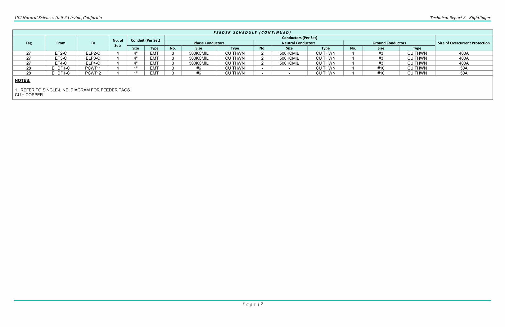
F E E D E R S C H E D U L E ( C O N T I N U E D )
Tag From To No. of Sets
Conduit (Per Set) Conductors (Per Set)
Size of Overcurrent Protection Phase Conductors Neutral Conductors Ground Conductors
Size Type No. Size Type No. Size Type No. Size Type
27 ET2-C ELP2-C 1 4" EMT 3 500KCMIL CU THWN 2 500KCMIL CU THWN 1 #3 CU THWN 400A 27 ET3-C ELP3-C 1 4" EMT 3 500KCMIL CU THWN 2 500KCMIL CU THWN 1 #3 CU THWN 400A 27 ET4-C ELP4-C 1 4" EMT 3 500KCMIL CU THWN 2 500KCMIL CU THWN 1 #3 CU THWN 400A 28 EHDP1-C PCWP 1 1 1" EMT 3 #6 CU THWN - - CU THWN 1 #10 CU THWN 50A 28 EHDP1-C PCWP 2 1 1" EMT 3 #6 CU THWN - - CU THWN 1 #10 CU THWN 50A
NOTES: 1. REFER TO SINGLE-LINE DIAGRAM FOR FEEDER TAGS CU = COPPER

UCI Natural Sciences Unit 2 | Irvine, California Technical Report 2 - Kightlinger
P a g e | 8
Summary Description of Distribution System
The electrical distribution system is a primary selective configuration with a service entrance to the electrical room at
the southeast corner of the main building. A 2500 KVA, 3Ø, 4W, pad-mounted transformer reduces the supply voltage
from 12kV to 480/277V. A 4000A main switchboard distributes power to subsequent panel boards throughout the
building. Emergency backup power is provided by a 1250 KW, 480/277V diesel generator located in the high energy lab
building. The emergency power system feeds life safety and lab critical distribution panels for the building. Additional
distribution information regarding loads can be found in the Voltage Systems section of this report.
Util ity Company Information
Natural Science Unit 2 is connected to the University of California Irvine utility distribution system. Underground utility
tunnels feed into the electrical room on the first floor of the building. The university system as a whole is served by:
Southern California Edison
P.O. Box 800
Rosemead, CA 91770
1-800-990-7788
http://www.sce.com/
The rate structure that applies to the UCI campus is referred to as “TOU-8” by the utility company, characterized by a
monthly registered demand of greater than 500kW. The time-of-use plan applies two separate rate schedules for
summer and winter seasons, with maximum energy rates charged between noon and 6:00pm from the month of June
through October. A detailed description of the schedule can be found on the Southern California Edison website.
Service Entrance
Electrical power enters the building at the unit substation in room 1160 on the first floor of the building. A 15kV air
switch and Kirk Key Interlock system is followed by a 2500kVA pad-mounted transformer to reduce the incoming
voltage. All transformer and service entrance equipment is maintained by the university.
Voltage Systems
Two 480/277V panel boards on each floor are fed directly from the main switchboard. One of these panels distributes
power predominantly to lighting systems on that floor, and the other to mechanical equipment. In addition, a step-down
transformer and 208/120V distribution panel is located on each floor. This panel feeds subsequent panels which operate
at the reduced voltage, typically occupied by receptacles and special equipment loads (window shades, refrigerators,
garbage disposals, etc.).
The emergency system is organized in a similar fashion, with some higher-voltage panels operating at 480Y/277V, and
some lower-voltage loads requiring a step-down transformer.
UCI Natural Sciences Unit 2 | Irvine, California Technical Report 2 - Kightlinger
P a g e | 9
Emergency Power System
The 1250 KW, 480/277V diesel generator located in the high energy lab building provides backup power for the entire
building. A 2000A 480/277V emergency distribution board then feeds two automatic transfer switches (ATS), one for life
safety and one for lab critical systems.
The life safety ATS is rated at 800A and connects to a distribution panel serving egress lighting, exit signs, fire alarm
systems, exhaust fans, and other life safety systems. The exhaust fans operate at 480V while the other systems require
step down transformers to provide 208Y/120V power.
Lab critical loads include fume hoods, lab benches, ventilation, and dedicated receptacles which would damage
equipment or cause major inconvenience if power was temporarily interrupted. The lab critical ATS is rated at 600A and
the panel organization is similar to that of the life safety branch.
For more information regarding the organization of the emergency power system, see the single-line and riser diagrams
included in this report.
UCI Natural Sciences Unit 2 | Irvine, California Technical Report 2 - Kightlinger
P a g e | 10
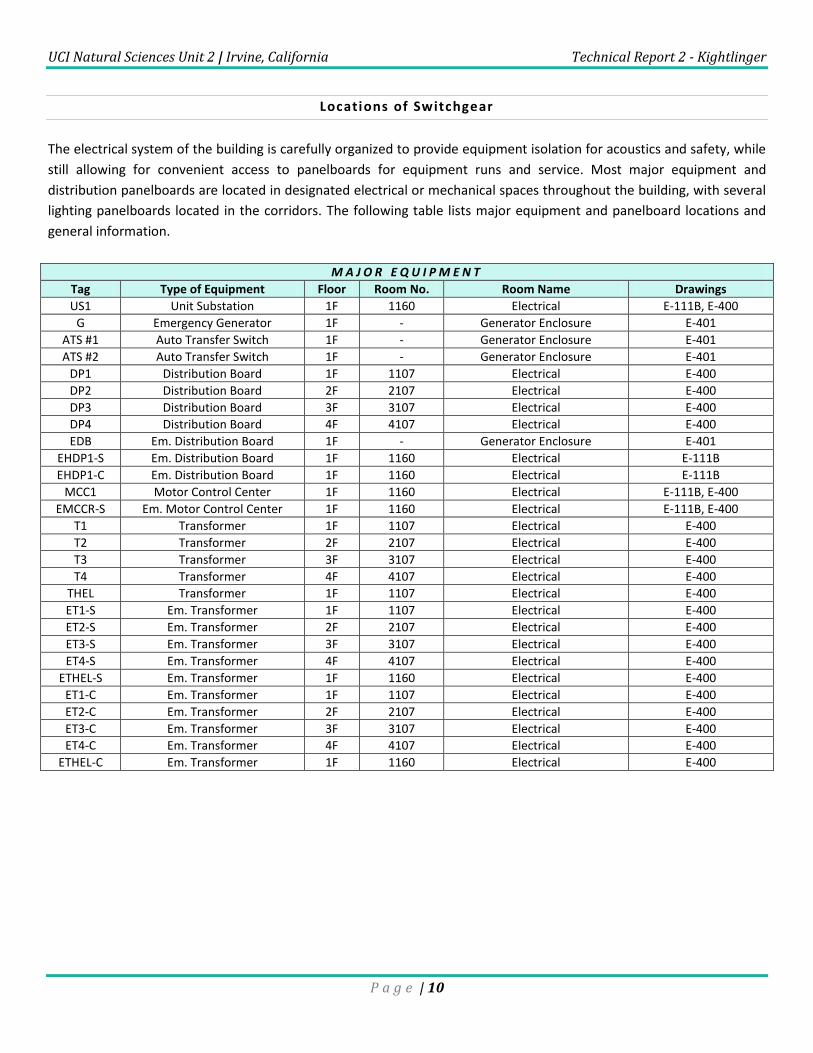
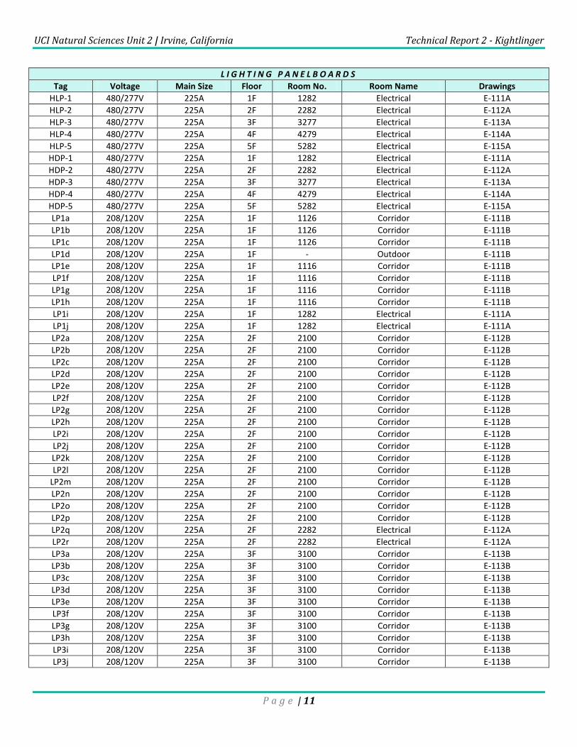
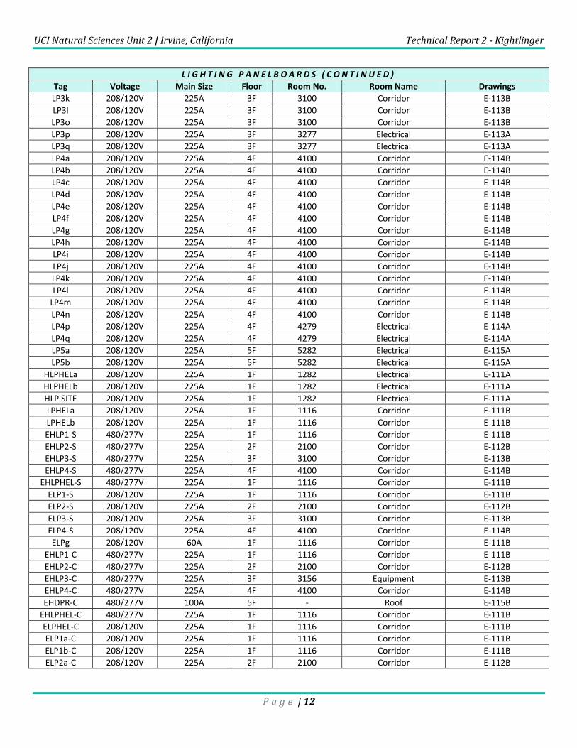
Locations of Switchgear
The electrical system of the building is carefully organized to provide equipment isolation for acoustics and safety, while
still allowing for convenient access to panelboards for equipment runs and service. Most major equipment and
distribution panelboards are located in designated electrical or mechanical spaces throughout the building, with several
lighting panelboards located in the corridors. The following table lists major equipment and panelboard locations and
general information.
M A J O R E Q U I P M E N T
Tag Type of Equipment Floor Room No. Room Name Drawings
US1 Unit Substation 1F 1160 Electrical E-111B, E-400
G Emergency Generator 1F - Generator Enclosure E-401
ATS #1 Auto Transfer Switch 1F - Generator Enclosure E-401
ATS #2 Auto Transfer Switch 1F - Generator Enclosure E-401
DP1 Distribution Board 1F 1107 Electrical E-400
DP2 Distribution Board 2F 2107 Electrical E-400
DP3 Distribution Board 3F 3107 Electrical E-400
DP4 Distribution Board 4F 4107 Electrical E-400
EDB Em. Distribution Board 1F - Generator Enclosure E-401
EHDP1-S Em. Distribution Board 1F 1160 Electrical E-111B
EHDP1-C Em. Distribution Board 1F 1160 Electrical E-111B
MCC1 Motor Control Center 1F 1160 Electrical E-111B, E-400
EMCCR-S Em. Motor Control Center 1F 1160 Electrical E-111B, E-400
T1 Transformer 1F 1107 Electrical E-400
T2 Transformer 2F 2107 Electrical E-400
T3 Transformer 3F 3107 Electrical E-400
T4 Transformer 4F 4107 Electrical E-400
THEL Transformer 1F 1107 Electrical E-400
ET1-S Em. Transformer 1F 1107 Electrical E-400
ET2-S Em. Transformer 2F 2107 Electrical E-400
ET3-S Em. Transformer 3F 3107 Electrical E-400
ET4-S Em. Transformer 4F 4107 Electrical E-400
ETHEL-S Em. Transformer 1F 1160 Electrical E-400
ET1-C Em. Transformer 1F 1107 Electrical E-400
ET2-C Em. Transformer 2F 2107 Electrical E-400
ET3-C Em. Transformer 3F 3107 Electrical E-400
ET4-C Em. Transformer 4F 4107 Electrical E-400
ETHEL-C Em. Transformer 1F 1160 Electrical E-400
UCI Natural Sciences Unit 2 | Irvine, California Technical Report 2 - Kightlinger
P a g e | 11
L I G H T I N G P A N E L B O A R D S
Tag Voltage Main Size Floor Room No. Room Name Drawings
HLP-1 480/277V 225A 1F 1282 Electrical E-111A
HLP-2 480/277V 225A 2F 2282 Electrical E-112A
HLP-3 480/277V 225A 3F 3277 Electrical E-113A
HLP-4 480/277V 225A 4F 4279 Electrical E-114A
HLP-5 480/277V 225A 5F 5282 Electrical E-115A
HDP-1 480/277V 225A 1F 1282 Electrical E-111A
HDP-2 480/277V 225A 2F 2282 Electrical E-112A
HDP-3 480/277V 225A 3F 3277 Electrical E-113A
HDP-4 480/277V 225A 4F 4279 Electrical E-114A
HDP-5 480/277V 225A 5F 5282 Electrical E-115A
LP1a 208/120V 225A 1F 1126 Corridor E-111B
LP1b 208/120V 225A 1F 1126 Corridor E-111B
LP1c 208/120V 225A 1F 1126 Corridor E-111B
LP1d 208/120V 225A 1F - Outdoor E-111B
LP1e 208/120V 225A 1F 1116 Corridor E-111B
LP1f 208/120V 225A 1F 1116 Corridor E-111B
LP1g 208/120V 225A 1F 1116 Corridor E-111B
LP1h 208/120V 225A 1F 1116 Corridor E-111B
LP1i 208/120V 225A 1F 1282 Electrical E-111A
LP1j 208/120V 225A 1F 1282 Electrical E-111A
LP2a 208/120V 225A 2F 2100 Corridor E-112B
LP2b 208/120V 225A 2F 2100 Corridor E-112B
LP2c 208/120V 225A 2F 2100 Corridor E-112B
LP2d 208/120V 225A 2F 2100 Corridor E-112B
LP2e 208/120V 225A 2F 2100 Corridor E-112B
LP2f 208/120V 225A 2F 2100 Corridor E-112B
LP2g 208/120V 225A 2F 2100 Corridor E-112B
LP2h 208/120V 225A 2F 2100 Corridor E-112B
LP2i 208/120V 225A 2F 2100 Corridor E-112B
LP2j 208/120V 225A 2F 2100 Corridor E-112B
LP2k 208/120V 225A 2F 2100 Corridor E-112B
LP2l 208/120V 225A 2F 2100 Corridor E-112B
LP2m 208/120V 225A 2F 2100 Corridor E-112B
LP2n 208/120V 225A 2F 2100 Corridor E-112B
LP2o 208/120V 225A 2F 2100 Corridor E-112B
LP2p 208/120V 225A 2F 2100 Corridor E-112B
LP2q 208/120V 225A 2F 2282 Electrical E-112A
LP2r 208/120V 225A 2F 2282 Electrical E-112A
LP3a 208/120V 225A 3F 3100 Corridor E-113B
LP3b 208/120V 225A 3F 3100 Corridor E-113B
LP3c 208/120V 225A 3F 3100 Corridor E-113B
LP3d 208/120V 225A 3F 3100 Corridor E-113B
LP3e 208/120V 225A 3F 3100 Corridor E-113B
LP3f 208/120V 225A 3F 3100 Corridor E-113B
LP3g 208/120V 225A 3F 3100 Corridor E-113B
LP3h 208/120V 225A 3F 3100 Corridor E-113B
LP3i 208/120V 225A 3F 3100 Corridor E-113B
LP3j 208/120V 225A 3F 3100 Corridor E-113B
UCI Natural Sciences Unit 2 | Irvine, California Technical Report 2 - Kightlinger
P a g e | 12
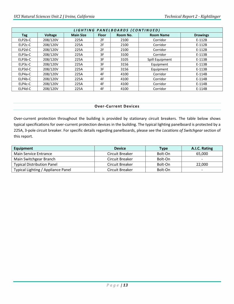
L I G H T I N G P A N E L B O A R D S ( C O N T I N U E D )
Tag Voltage Main Size Floor Room No. Room Name Drawings
LP3k 208/120V 225A 3F 3100 Corridor E-113B
LP3l 208/120V 225A 3F 3100 Corridor E-113B
LP3o 208/120V 225A 3F 3100 Corridor E-113B
LP3p 208/120V 225A 3F 3277 Electrical E-113A
LP3q 208/120V 225A 3F 3277 Electrical E-113A
LP4a 208/120V 225A 4F 4100 Corridor E-114B
LP4b 208/120V 225A 4F 4100 Corridor E-114B
LP4c 208/120V 225A 4F 4100 Corridor E-114B
LP4d 208/120V 225A 4F 4100 Corridor E-114B
LP4e 208/120V 225A 4F 4100 Corridor E-114B
LP4f 208/120V 225A 4F 4100 Corridor E-114B
LP4g 208/120V 225A 4F 4100 Corridor E-114B
LP4h 208/120V 225A 4F 4100 Corridor E-114B
LP4i 208/120V 225A 4F 4100 Corridor E-114B
LP4j 208/120V 225A 4F 4100 Corridor E-114B
LP4k 208/120V 225A 4F 4100 Corridor E-114B
LP4l 208/120V 225A 4F 4100 Corridor E-114B
LP4m 208/120V 225A 4F 4100 Corridor E-114B
LP4n 208/120V 225A 4F 4100 Corridor E-114B
LP4p 208/120V 225A 4F 4279 Electrical E-114A
LP4q 208/120V 225A 4F 4279 Electrical E-114A
LP5a 208/120V 225A 5F 5282 Electrical E-115A
LP5b 208/120V 225A 5F 5282 Electrical E-115A
HLPHELa 208/120V 225A 1F 1282 Electrical E-111A
HLPHELb 208/120V 225A 1F 1282 Electrical E-111A
HLP SITE 208/120V 225A 1F 1282 Electrical E-111A
LPHELa 208/120V 225A 1F 1116 Corridor E-111B
LPHELb 208/120V 225A 1F 1116 Corridor E-111B
EHLP1-S 480/277V 225A 1F 1116 Corridor E-111B
EHLP2-S 480/277V 225A 2F 2100 Corridor E-112B
EHLP3-S 480/277V 225A 3F 3100 Corridor E-113B
EHLP4-S 480/277V 225A 4F 4100 Corridor E-114B
EHLPHEL-S 480/277V 225A 1F 1116 Corridor E-111B
ELP1-S 208/120V 225A 1F 1116 Corridor E-111B
ELP2-S 208/120V 225A 2F 2100 Corridor E-112B
ELP3-S 208/120V 225A 3F 3100 Corridor E-113B
ELP4-S 208/120V 225A 4F 4100 Corridor E-114B
ELPg 208/120V 60A 1F 1116 Corridor E-111B
EHLP1-C 480/277V 225A 1F 1116 Corridor E-111B
EHLP2-C 480/277V 225A 2F 2100 Corridor E-112B
EHLP3-C 480/277V 225A 3F 3156 Equipment E-113B
EHLP4-C 480/277V 225A 4F 4100 Corridor E-114B
EHDPR-C 480/277V 100A 5F - Roof E-115B
EHLPHEL-C 480/277V 225A 1F 1116 Corridor E-111B
ELPHEL-C 208/120V 225A 1F 1116 Corridor E-111B
ELP1a-C 208/120V 225A 1F 1116 Corridor E-111B
ELP1b-C 208/120V 225A 1F 1116 Corridor E-111B
ELP2a-C 208/120V 225A 2F 2100 Corridor E-112B
UCI Natural Sciences Unit 2 | Irvine, California Technical Report 2 - Kightlinger
P a g e | 13
L I G H T I N G P A N E L B O A R D S ( C O N T I N U E D )
Tag Voltage Main Size Floor Room No. Room Name Drawings
ELP2b-C 208/120V 225A 2F 2100 Corridor E-112B
ELP2c-C 208/120V 225A 2F 2100 Corridor E-112B
ELP2d-C 208/120V 225A 2F 2100 Corridor E-112B
ELP3a-C 208/120V 225A 3F 3100 Corridor E-113B
ELP3b-C 208/120V 225A 3F 3105 Spill Equipment E-113B
ELP3c-C 208/120V 225A 3F 3156 Equipment E-113B
ELP3d-C 208/120V 225A 3F 3156 Equipment E-113B
ELP4a-C 208/120V 225A 4F 4100 Corridor E-114B
ELP4b-C 208/120V 225A 4F 4100 Corridor E-114B
ELP4c-C 208/120V 225A 4F 4100 Corridor E-114B
ELP4d-C 208/120V 225A 4F 4100 Corridor E-114B
Over-Current Devices
Over-current protection throughout the building is provided by stationary circuit breakers. The table below shows
typical specifications for over-current protection devices in the building. The typical lighting panelboard is protected by a
225A, 3-pole circuit breaker. For specific details regarding panelboards, please see the Locations of Switchgear section of
this report.
Equipment Device Type A.I.C. Rating
Main Service Entrance Circuit Breaker Bolt-On 65,000
Main Switchgear Branch Circuit Breaker Bolt-On -
Typical Distribution Panel Circuit Breaker Bolt-On 22,000
Typical Lighting / Appliance Panel Circuit Breaker Bolt-On -
UCI Natural Sciences Unit 2 | Irvine, California Technical Report 2 - Kightlinger
P a g e | 14
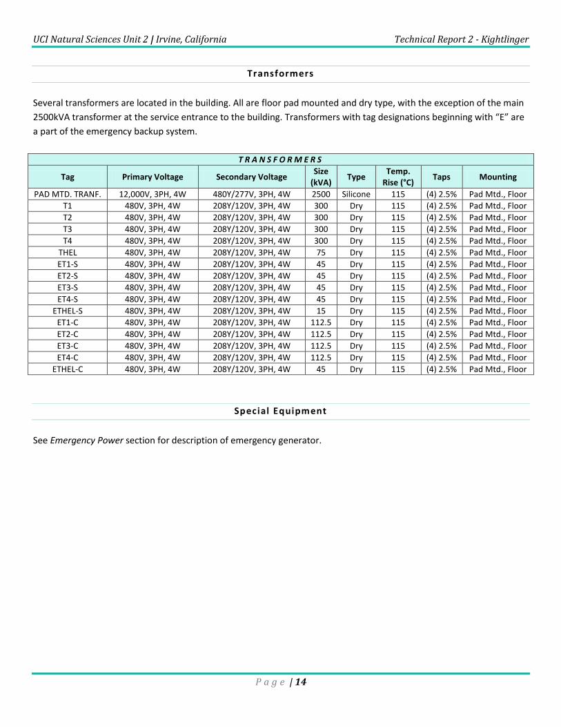
Transformers
Several transformers are located in the building. All are floor pad mounted and dry type, with the exception of the main
2500kVA transformer at the service entrance to the building. Transformers with tag designations beginning with “E” are
a part of the emergency backup system.
T R A N S F O R M E R S
Tag Primary Voltage Secondary Voltage Size
(kVA) Type
Temp. Rise (°C)
Taps Mounting
PAD MTD. TRANF. 12,000V, 3PH, 4W 480Y/277V, 3PH, 4W 2500 Silicone 115 (4) 2.5% Pad Mtd., Floor
T1 480V, 3PH, 4W 208Y/120V, 3PH, 4W 300 Dry 115 (4) 2.5% Pad Mtd., Floor
T2 480V, 3PH, 4W 208Y/120V, 3PH, 4W 300 Dry 115 (4) 2.5% Pad Mtd., Floor
T3 480V, 3PH, 4W 208Y/120V, 3PH, 4W 300 Dry 115 (4) 2.5% Pad Mtd., Floor
T4 480V, 3PH, 4W 208Y/120V, 3PH, 4W 300 Dry 115 (4) 2.5% Pad Mtd., Floor
THEL 480V, 3PH, 4W 208Y/120V, 3PH, 4W 75 Dry 115 (4) 2.5% Pad Mtd., Floor
ET1-S 480V, 3PH, 4W 208Y/120V, 3PH, 4W 45 Dry 115 (4) 2.5% Pad Mtd., Floor
ET2-S 480V, 3PH, 4W 208Y/120V, 3PH, 4W 45 Dry 115 (4) 2.5% Pad Mtd., Floor
ET3-S 480V, 3PH, 4W 208Y/120V, 3PH, 4W 45 Dry 115 (4) 2.5% Pad Mtd., Floor
ET4-S 480V, 3PH, 4W 208Y/120V, 3PH, 4W 45 Dry 115 (4) 2.5% Pad Mtd., Floor
ETHEL-S 480V, 3PH, 4W 208Y/120V, 3PH, 4W 15 Dry 115 (4) 2.5% Pad Mtd., Floor
ET1-C 480V, 3PH, 4W 208Y/120V, 3PH, 4W 112.5 Dry 115 (4) 2.5% Pad Mtd., Floor
ET2-C 480V, 3PH, 4W 208Y/120V, 3PH, 4W 112.5 Dry 115 (4) 2.5% Pad Mtd., Floor
ET3-C 480V, 3PH, 4W 208Y/120V, 3PH, 4W 112.5 Dry 115 (4) 2.5% Pad Mtd., Floor
ET4-C 480V, 3PH, 4W 208Y/120V, 3PH, 4W 112.5 Dry 115 (4) 2.5% Pad Mtd., Floor
ETHEL-C 480V, 3PH, 4W 208Y/120V, 3PH, 4W 45 Dry 115 (4) 2.5% Pad Mtd., Floor
Special Equipment
See Emergency Power section for description of emergency generator.
UCI Natural Sciences Unit 2 | Irvine, California Technical Report 2 - Kightlinger
P a g e | 15
Lighting Loads
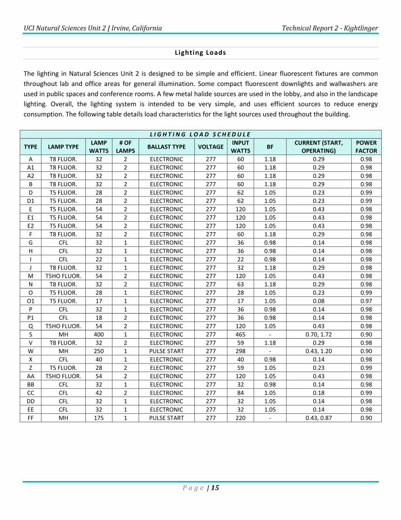
The lighting in Natural Sciences Unit 2 is designed to be simple and efficient. Linear fluorescent fixtures are common
throughout lab and office areas for general illumination. Some compact fluorescent downlights and wallwashers are
used in public spaces and conference rooms. A few metal halide sources are used in the lobby, and also in the landscape
lighting. Overall, the lighting system is intended to be very simple, and uses efficient sources to reduce energy
consumption. The following table details load characteristics for the light sources used throughout the building.
L I G H T I N G L O A D S C H E D U L E
TYPE LAMP TYPE LAMP
WATTS # OF
LAMPS BALLAST TYPE VOLTAGE
INPUT WATTS
BF CURRENT (START,
OPERATING) POWER FACTOR
A T8 FLUOR. 32 2 ELECTRONIC 277 60 1.18 0.29 0.98
A1 T8 FLUOR. 32 2 ELECTRONIC 277 60 1.18 0.29 0.98
A2 T8 FLUOR. 32 2 ELECTRONIC 277 60 1.18 0.29 0.98
B T8 FLUOR. 32 2 ELECTRONIC 277 60 1.18 0.29 0.98
D T5 FLUOR. 28 2 ELECTRONIC 277 62 1.05 0.23 0.99
D1 T5 FLUOR. 28 2 ELECTRONIC 277 62 1.05 0.23 0.99
E T5 FLUOR. 54 2 ELECTRONIC 277 120 1.05 0.43 0.98
E1 T5 FLUOR. 54 2 ELECTRONIC 277 120 1.05 0.43 0.98
E2 T5 FLUOR. 54 2 ELECTRONIC 277 120 1.05 0.43 0.98
F T8 FLUOR. 32 2 ELECTRONIC 277 60 1.18 0.29 0.98
G CFL 32 1 ELECTRONIC 277 36 0.98 0.14 0.98
H CFL 32 1 ELECTRONIC 277 36 0.98 0.14 0.98
I CFL 22 1 ELECTRONIC 277 22 0.98 0.14 0.98
J T8 FLUOR. 32 1 ELECTRONIC 277 32 1.18 0.29 0.98
M T5HO FLUOR. 54 2 ELECTRONIC 277 120 1.05 0.43 0.98
N T8 FLUOR. 32 2 ELECTRONIC 277 63 1.18 0.29 0.98
O T5 FLUOR. 28 1 ELECTRONIC 277 28 1.05 0.23 0.99
O1 T5 FLUOR. 17 1 ELECTRONIC 277 17 1.05 0.08 0.97
P CFL 32 1 ELECTRONIC 277 36 0.98 0.14 0.98
P1 CFL 18 2 ELECTRONIC 277 36 0.98 0.14 0.98
Q T5HO FLUOR. 54 2 ELECTRONIC 277 120 1.05 0.43 0.98
S MH 400 1 ELECTRONIC 277 465 - 0.70, 1.72 0.90
V T8 FLUOR. 32 2 ELECTRONIC 277 59 1.18 0.29 0.98
W MH 250 1 PULSE START 277 298 - 0.43, 1.20 0.90
X CFL 40 1 ELECTRONIC 277 40 0.98 0.14 0.98
Z T5 FLUOR. 28 2 ELECTRONIC 277 59 1.05 0.23 0.99
AA T5HO FLUOR. 54 2 ELECTRONIC 277 120 1.05 0.43 0.98
BB CFL 32 1 ELECTRONIC 277 32 0.98 0.14 0.98
CC CFL 42 2 ELECTRONIC 277 84 1.05 0.18 0.99
DD CFL 32 1 ELECTRONIC 277 32 1.05 0.14 0.98
EE CFL 32 1 ELECTRONIC 277 32 1.05 0.14 0.98
FF MH 175 1 PULSE START 277 220 - 0.43, 0.87 0.90
UCI Natural Sciences Unit 2 | Irvine, California Technical Report 2 - Kightlinger
P a g e | 16
Mechanical and Other Loads
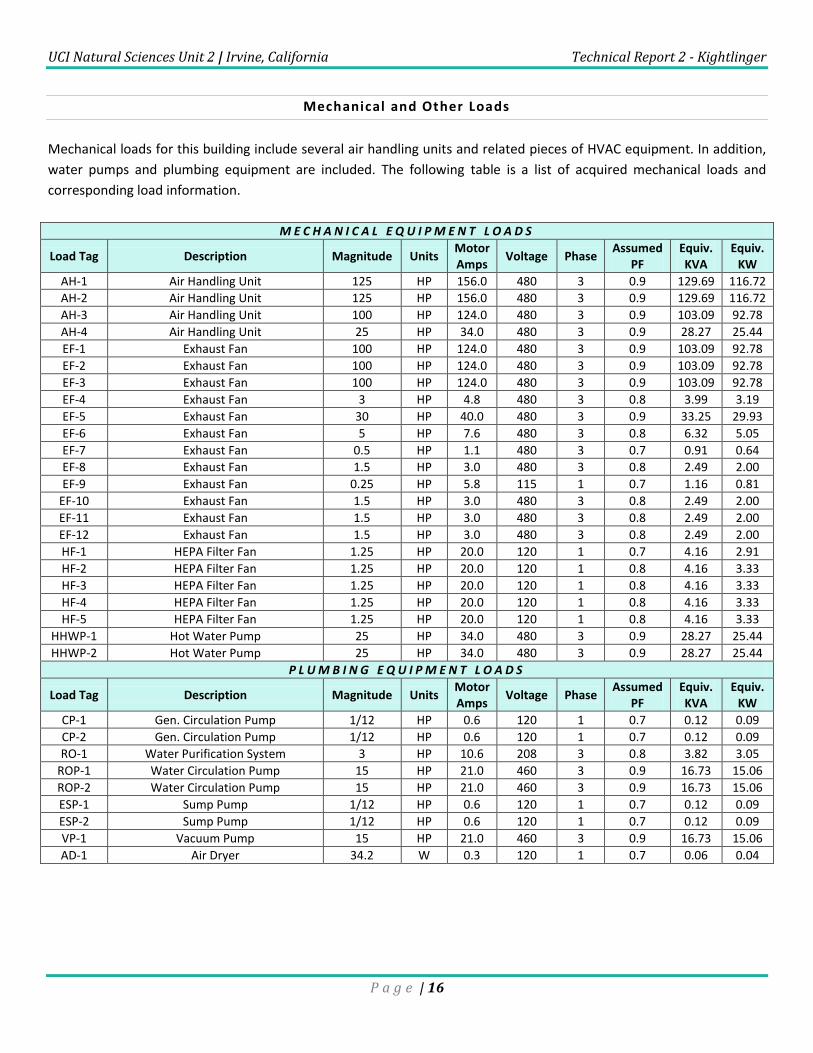
Mechanical loads for this building include several air handling units and related pieces of HVAC equipment. In addition,
water pumps and plumbing equipment are included. The following table is a list of acquired mechanical loads and
corresponding load information.
M E C H A N I C A L E Q U I P M E N T L O A D S
Load Tag Description Magnitude Units Motor Amps
Voltage Phase Assumed
PF Equiv. KVA
Equiv. KW
AH-1 Air Handling Unit 125 HP 156.0 480 3 0.9 129.69 116.72
AH-2 Air Handling Unit 125 HP 156.0 480 3 0.9 129.69 116.72
AH-3 Air Handling Unit 100 HP 124.0 480 3 0.9 103.09 92.78
AH-4 Air Handling Unit 25 HP 34.0 480 3 0.9 28.27 25.44
EF-1 Exhaust Fan 100 HP 124.0 480 3 0.9 103.09 92.78
EF-2 Exhaust Fan 100 HP 124.0 480 3 0.9 103.09 92.78
EF-3 Exhaust Fan 100 HP 124.0 480 3 0.9 103.09 92.78
EF-4 Exhaust Fan 3 HP 4.8 480 3 0.8 3.99 3.19
EF-5 Exhaust Fan 30 HP 40.0 480 3 0.9 33.25 29.93
EF-6 Exhaust Fan 5 HP 7.6 480 3 0.8 6.32 5.05
EF-7 Exhaust Fan 0.5 HP 1.1 480 3 0.7 0.91 0.64
EF-8 Exhaust Fan 1.5 HP 3.0 480 3 0.8 2.49 2.00
EF-9 Exhaust Fan 0.25 HP 5.8 115 1 0.7 1.16 0.81
EF-10 Exhaust Fan 1.5 HP 3.0 480 3 0.8 2.49 2.00
EF-11 Exhaust Fan 1.5 HP 3.0 480 3 0.8 2.49 2.00
EF-12 Exhaust Fan 1.5 HP 3.0 480 3 0.8 2.49 2.00
HF-1 HEPA Filter Fan 1.25 HP 20.0 120 1 0.7 4.16 2.91
HF-2 HEPA Filter Fan 1.25 HP 20.0 120 1 0.8 4.16 3.33
HF-3 HEPA Filter Fan 1.25 HP 20.0 120 1 0.8 4.16 3.33
HF-4 HEPA Filter Fan 1.25 HP 20.0 120 1 0.8 4.16 3.33
HF-5 HEPA Filter Fan 1.25 HP 20.0 120 1 0.8 4.16 3.33
HHWP-1 Hot Water Pump 25 HP 34.0 480 3 0.9 28.27 25.44
HHWP-2 Hot Water Pump 25 HP 34.0 480 3 0.9 28.27 25.44
P L U M B I N G E Q U I P M E N T L O A D S
Load Tag Description Magnitude Units Motor Amps
Voltage Phase Assumed
PF Equiv. KVA
Equiv. KW
CP-1 Gen. Circulation Pump 1/12 HP 0.6 120 1 0.7 0.12 0.09
CP-2 Gen. Circulation Pump 1/12 HP 0.6 120 1 0.7 0.12 0.09
RO-1 Water Purification System 3 HP 10.6 208 3 0.8 3.82 3.05
ROP-1 Water Circulation Pump 15 HP 21.0 460 3 0.9 16.73 15.06
ROP-2 Water Circulation Pump 15 HP 21.0 460 3 0.9 16.73 15.06
ESP-1 Sump Pump 1/12 HP 0.6 120 1 0.7 0.12 0.09
ESP-2 Sump Pump 1/12 HP 0.6 120 1 0.7 0.12 0.09
VP-1 Vacuum Pump 15 HP 21.0 460 3 0.9 16.73 15.06
AD-1 Air Dryer 34.2 W 0.3 120 1 0.7 0.06 0.04
UCI Natural Sciences Unit 2 | Irvine, California Technical Report 2 - Kightlinger
P a g e | 17
Service Entrance Size
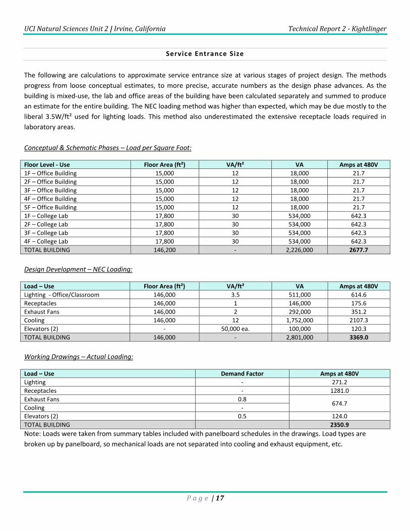
The following are calculations to approximate service entrance size at various stages of project design. The methods
progress from loose conceptual estimates, to more precise, accurate numbers as the design phase advances. As the
building is mixed-use, the lab and office areas of the building have been calculated separately and summed to produce
an estimate for the entire building. The NEC loading method was higher than expected, which may be due mostly to the
liberal 3.5W/ft² used for lighting loads. This method also underestimated the extensive receptacle loads required in
laboratory areas.
Conceptual & Schematic Phases – Load per Square Foot:
Floor Level - Use Floor Area (ft²) VA/ft² VA Amps at 480V
1F – Office Building 15,000 12 18,000 21.7
2F – Office Building 15,000 12 18,000 21.7
3F – Office Building 15,000 12 18,000 21.7
4F – Office Building 15,000 12 18,000 21.7
5F – Office Building 15,000 12 18,000 21.7
1F – College Lab 17,800 30 534,000 642.3
2F – College Lab 17,800 30 534,000 642.3
3F – College Lab 17,800 30 534,000 642.3
4F – College Lab 17,800 30 534,000 642.3
TOTAL BUILDING 146,200 - 2,226,000 2677.7
Design Development – NEC Loading:
Load – Use Floor Area (ft²) VA/ft² VA Amps at 480V
Lighting - Office/Classroom 146,000 3.5 511,000 614.6
Receptacles 146,000 1 146,000 175.6
Exhaust Fans 146,000 2 292,000 351.2
Cooling 146,000 12 1,752,000 2107.3
Elevators (2) - 50,000 ea. 100,000 120.3
TOTAL BUILDING 146,000 - 2,801,000 3369.0
Working Drawings – Actual Loading:
Load – Use Demand Factor Amps at 480V
Lighting - 271.2
Receptacles - 1281.0
Exhaust Fans 0.8 674.7
Cooling -
Elevators (2) 0.5 124.0
TOTAL BUILDING 2350.9
Note: Loads were taken from summary tables included with panelboard schedules in the drawings. Load types are
broken up by panelboard, so mechanical loads are not separated into cooling and exhaust equipment, etc.
UCI Natural Sciences Unit 2 | Irvine, California Technical Report 2 - Kightlinger
P a g e | 18
Summary Table:
Design Phase Calculated kVA Voltage System Amps at 480V
Conceptual / Schematic 2,226 480 2677.7
Design Development 2,801 480 3369.0
Working Drawings - 480 2350.9
Environmental Stewardship Design
Fluorescent and compact fluorescent lighting systems are used widely throughout the project. Stringent California
building codes ensure that the lighting design is highly efficient. A Power Monitoring, Analysis and Control (PMAC)
system has been installed to collect and diagnose data in order to optimize power and resource usage in the building. No
information on LEED rating is available at this time.
Design Issues
The design of the building required some special consideration due to its use. Since nearly half of the building consists of
college laboratory spaces, availability and placement of electrical outlets was important. The building systems are
chosen to meet stringent California code standards for energy use.
Communication Systems
Voice/Data:
The building’s main distribution frame in the first floor data room (rm. 1109) is connected to the campus utility tunnel
system through underground conduit. Vertically stacked data rooms are located on each floor and act as access points
for wiring and conduit. Combination voice/data outlets are located throughout the building.
Audio/Video:
Audiovisual systems are installed in the conference rooms on each floor. A projector is mounted on the ceiling with data
input terminals near the south wall of each room. An automatic projection screen is operated by a switch on the south
wall.
Fire Alarm:
The fire detection and suppression system features a central control center with interface panel. Fire sprinkler flow and
tamper switches, elevator status, smoke fire dampers and relays can be monitored and controlled through the interface
panel. Visible and audible cues are used to alert occupants in an emergency situation. The entire fire system is backed
up by a dedicated battery system.
Job:Type:
Notes:
DF7 - 7" DIAMETERDESIGNER FLOOD
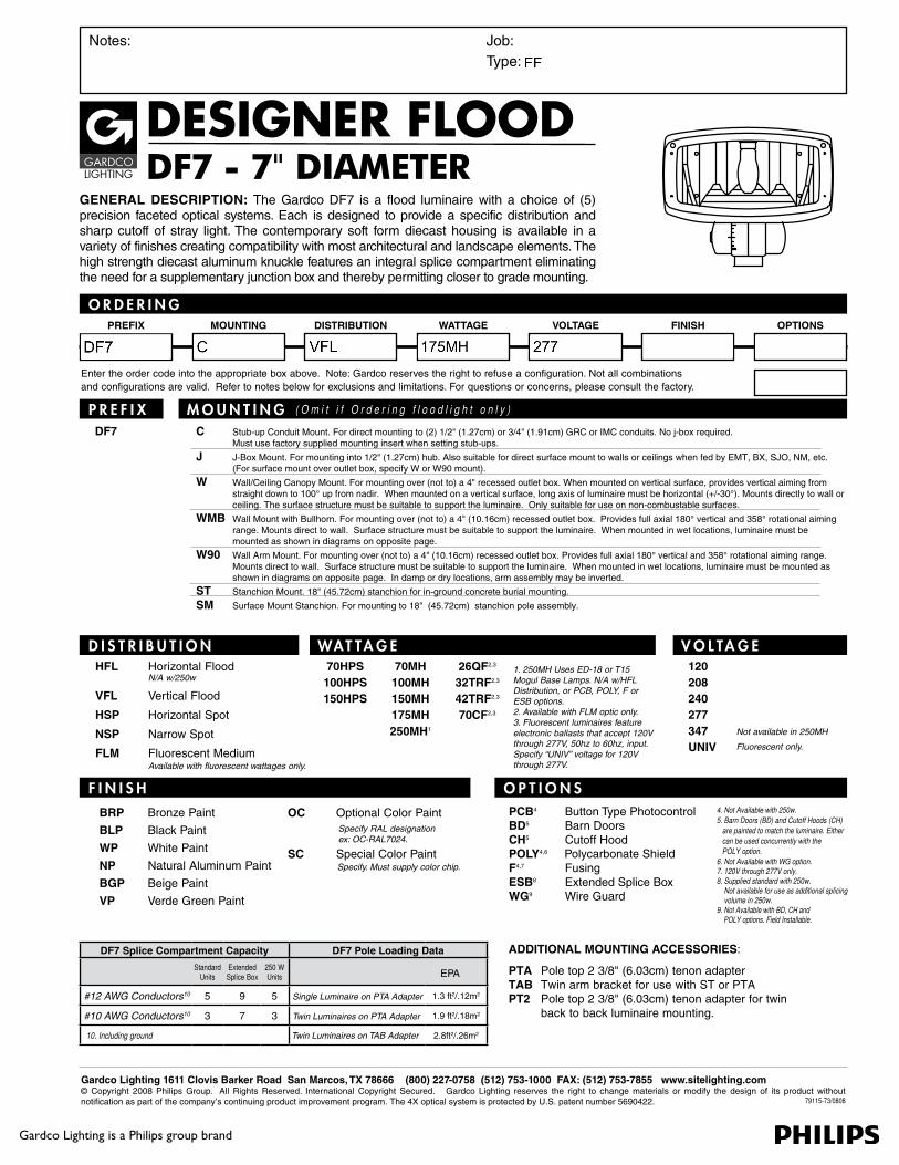
GENERAL DESCRIPTION: The Gardco DF7 is a flood luminaire with a choice of (5) precision faceted optical systems. Each is designed to provide a specific distribution and sharp cutoff of stray light. The contemporary soft form diecast housing is available in a variety of finishes creating compatibility with most architectural and landscape elements. The high strength diecast aluminum knuckle features an integral splice compartment eliminating the need for a supplementary junction box and thereby permitting closer to grade mounting.
O R D E R I N GPREFIX MOUNTING WATTAGEDISTRIBUTION VOLTAGE FINISH OPTIONS
Enter the order code into the appropriate box above. Note: Gardco reserves the right to refuse a configuration. Not all combinations and configurations are valid. Refer to notes below for exclusions and limitations. For questions or concerns, please consult the factory.
Gardco Lighting 1611 Clovis Barker Road San Marcos, TX 78666 (800) 227-0758 (512) 753-1000 FAX: (512) 753-7855 www.sitelighting.com© Copyright 2008 Philips Group. All Rights Reserved. International Copyright Secured. Gardco Lighting reserves the right to change materials or modify the design of its product without notification as part of the company’s continuing product improvement program. The 4X optical system is protected by U.S. patent number 5690422.
Gardco Lighting is a Philips group brand
79115-73/0808
C Stub-up Conduit Mount. For direct mounting to (2) 1/2" (1.27cm) or 3/4" (1.91cm) GRC or IMC conduits. No j-box required. Must use factory supplied mounting insert when setting stub-ups.
J J-Box Mount. For mounting into 1/2" (1.27cm) hub. Also suitable for direct surface mount to walls or ceilings when fed by EMT, BX, SJO, NM, etc. (For surface mount over outlet box, specify W or W90 mount).
W Wall/Ceiling Canopy Mount. For mounting over (not to) a 4" recessed outlet box. When mounted on vertical surface, provides vertical aiming from straight down to 100° up from nadir. When mounted on a vertical surface, long axis of luminaire must be horizontal (+/-30°). Mounts directly to wall or ceiling. The surface structure must be suitable to support the luminaire. Only suitable for use on non-combustable surfaces.
WMB Wall Mount with Bullhorn. For mounting over (not to) a 4" (10.16cm) recessed outlet box. Provides full axial 180° vertical and 358° rotational aiming range. Mounts direct to wall. Surface structure must be suitable to support the luminaire. When mounted in wet locations, luminaire must be mounted as shown in diagrams on opposite page.
W90 Wall Arm Mount. For mounting over (not to) a 4" (10.16cm) recessed outlet box. Provides full axial 180° vertical and 358° rotational aiming range. Mounts direct to wall. Surface structure must be suitable to support the luminaire. When mounted in wet locations, luminaire must be mounted as shown in diagrams on opposite page. In damp or dry locations, arm assembly may be inverted.
ST Stanchion Mount. 18" (45.72cm) stanchion for in-ground concrete burial mounting.
SM Surface Mount Stanchion. For mounting to 18" (45.72cm) stanchion pole assembly.
OC Optional Color Paint
SC Special Color Paint
DF7
P R E F I X
D I S T R I B U T I O N WAT TA G E V O L TA G E
F I N I S H O P T I O N S
M O U N T I N G ( O m i t i f O r d e r i n g f l o o d l i g h t o n l y )
BRP Bronze Paint
BLP Black Paint
WP White Paint
NP Natural Aluminum Paint
BGP Beige Paint
VP Verde Green Paint
Specify RAL designation ex: OC-RAL7024.
Specify. Must supply color chip.
HFL Horizontal Flood N/A w/250w
VFL Vertical Flood
HSP Horizontal Spot
NSP Narrow Spot
FLM Fluorescent Medium Available with fluorescent wattages only.
70HPS100HPS150HPS
70MH100MH150MH175MH250MH1
26QF2,3
32TRF2,3
42TRF2,3
70CF2,3
1. 250MH Uses ED-18 or T15 Mogul Base Lamps. N/A w/HFL Distribution, or PCB, POLY, F or ESB options.2. Available with FLM optic only.3. Fluorescent luminaires feature electronic ballasts that accept 120V through 277V, 50hz to 60hz, input. Specify “UNIV” voltage for 120V through 277V.
120208240277347UNIV
Not available in 250MH
Fluorescent only.
PCB4 Button Type Photocontrol BD5 Barn Doors CH5 Cutoff HoodPOLY4,6 Polycarbonate Shield F4,7 Fusing ESB8 Extended Splice Box WG9 Wire Guard
ADDITIONAL MOUNTING ACCESSORIES:
PTA Pole top 2 3/8" (6.03cm) tenon adapterTAB Twin arm bracket for use with ST or PTAPT2 Pole top 2 3/8" (6.03cm) tenon adapter for twin back to back luminaire mounting.
DF7 Splice Compartment Capacity DF7 Pole Loading Data
Standard Units
Extended Splice Box
250 W Units EPA
#12 AWG Conductors10 5 9 5 Single Luminaire on PTA Adapter 1.3 ft2/.12m2
#10 AWG Conductors10 3 7 3 Twin Luminaires on PTA Adapter 1.9 ft2/.18m2
10. Including ground Twin Luminaires on TAB Adapter 2.8ft2/.26m2
4. Not Available with 250w.5. Barn Doors (BD) and Cutoff Hoods (CH) are painted to match the luminaire. Either can be used concurrently with the POLY option.6. Not Available with WG option.7. 120V through 277V only.8. Supplied standard with 250w. Not available for use as additional splicing volume in 250w. 9. Not Available with BD, CH and POLY options. Field Installable.
Gardco Lighting is a Philips group brand
Gardco Lighting 1611 Clovis Barker Road San Marcos, TX 78666 (800) 227-0758 (512) 753-1000 FAX: (512) 753-7855 www.sitelighting.com© Copyright 2008 Philips Group. All Rights Reserved. International Copyright Secured. Gardco Lighting reserves the right to change materials or modify the design of its product without notification as part of the company’s continuing product improvement program. The 4X optical system is protected by U.S. patent number 5690422.
DF7- 7" DIAMETERDESIGNER FLOOD
S P E C I F I C AT I O N S
79115-73/0808
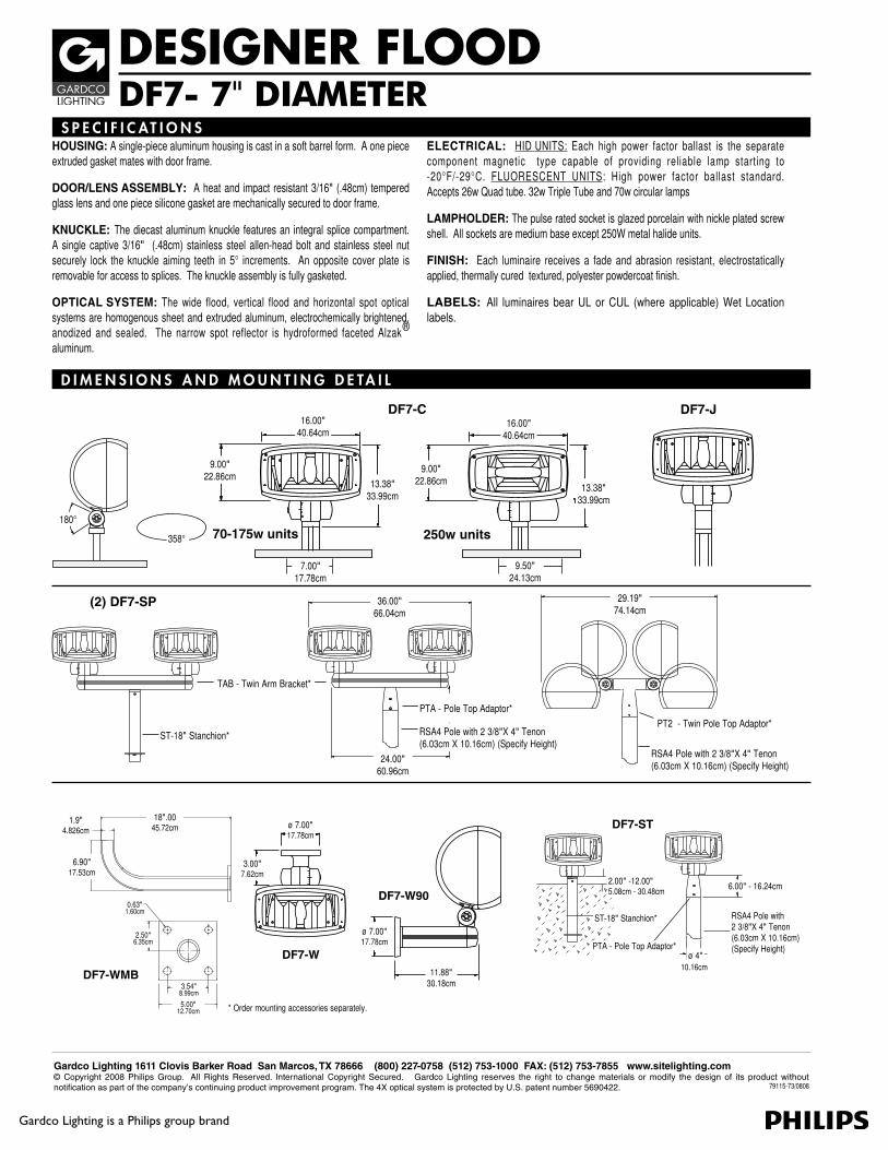
HOUSING: A single-piece aluminum housing is cast in a soft barrel form. A one piece extruded gasket mates with door frame.
DOOR/LENS ASSEMBLY: A heat and impact resistant 3/16" (.48cm) tempered glass lens and one piece silicone gasket are mechanically secured to door frame.
KNUCKLE: The diecast aluminum knuckle features an integral splice compartment. A single captive 3/16" (.48cm) stainless steel allen-head bolt and stainless steel nut securely lock the knuckle aiming teeth in 5° increments. An opposite cover plate is removable for access to splices. The knuckle assembly is fully gasketed.
OPTICAL SYSTEM: The wide flood, vertical flood and horizontal spot optical systems are homogenous sheet and extruded aluminum, electrochemically brightened, anodized and sealed. The narrow spot reflector is hydroformed faceted Alzak® aluminum.
ELECTRICAL: HID UNITS: Each high power factor ballast is the separate component magnetic type capable of providing reliable lamp starting to -20°F/-29°C. FLUORESCENT UNITS: High power factor ballast standard. Accepts 26w Quad tube. 32w Triple Tube and 70w circular lamps
LAMPHOLDER: The pulse rated socket is glazed porcelain with nickle plated screw shell. All sockets are medium base except 250W metal halide units.
FINISH: Each luminaire receives a fade and abrasion resistant, electrostatically applied, thermally cured textured, polyester powdercoat finish.
LABELS: All luminaires bear UL or CUL (where applicable) Wet Location labels.
180°
358°
16.00" 40.64cm
16.00" 40.64cm
9.00" 22.86cm
9.00" 22.86cm13.38"
33.99cm13.38"
33.99cm
DF7-C DF7-J
70-175w units 250w units
7.00" 17.78cm
(2) DF7-SP
TAB - Twin Arm Bracket*
ST-18" Stanchion*
PTA - Pole Top Adaptor*
RSA4 Pole with 2 3/8"X 4" Tenon (6.03cm X 10.16cm) (Specify Height)
36.00" 66.04cm
29.19" 74.14cm
PT2 - Twin Pole Top Adaptor*
RSA4 Pole with 2 3/8"X 4" Tenon (6.03cm X 10.16cm) (Specify Height)
24.00" 60.96cm
D I M E N S I O N S A N D M O U N T I N G D E TA I L
9.50" 24.13cm
* Order mounting accessories separately.
DF7-W
DF7-W90
ø 7.00" 17.78cm
ø 7.00" 17.78cm
3.00" 7.62cm
11.88" 30.18cm
DF7-ST
2.00" -12.00"5.08cm - 30.48cm
ST-18" Stanchion*
6.00" - 16.24cm
ø 4"10.16cm
PTA - Pole Top Adaptor*
DF7-WMB
18".00 45.72cm
6.90" 17.53cm
1.9"4.826cm
2.50"6.35cm
5.00" 12.70cm
3.54" 8.99cm
0.63"1.60cm RSA4 Pole with
2 3/8"X 4" Tenon (6.03cm X 10.16cm) (Specify Height)
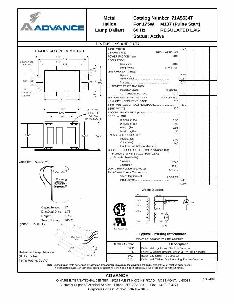
Metal
Halide
Lamp Ballast
Catalog Number 71A5534T
For 175W M137 (Pulse Start)
60 Hz REGULATED LAG
Status: Active
DIMENSIONS AND DATA
1.65"
7.75"
7.15"
B
MAX.
0.8"
0.25" WIDE
2 SLOTS
A
0.9"
1.75"
0.5"
2.8"
6.75"6.15"
0.312" X 0.531
4 SLOTS
5.75"
4 1/4 X 5 3/4 CORE - 3 COIL UNIT
3.90"
5.75"
5.40"
4.35"4.25"
8 HOLESCLEAREDFOR #10
THRU-BOLTS4.40"
Capacitor: 7C170P40
Capacitance: 17
Dia/Oval Dim: 1.75
Height: 3.75
Temp Rating: 105°C
1"
1/4" SLOT
43/4"
41/4"
25/32"3"
15/16"
Oval Ignitor
Case
Ballast to Lamp Distance
(BTL) = 2 feet
Temp Rating: 105°C
Ignitor: LI534-H5
Data is based upon tests performed by Advance Transformer in a controlled environment and representitive of relative performance.Actual performance can vary depending on operating conditions. Specifications are subject to change without notice.
ADVANCEO'HARE INTERNATIONAL CENTER · 10275 WEST HIGGINS ROAD · ROSEMONT, IL 60018
Customer Support/Technical Service: Phone: 800-372-3331 · Fax: 630-307-3071
Corporate Offices: Phone: 800-322-2086
INPUT VOLTS 277
CIRCUIT TYPE
POWER FACTOR (min)
REGULATION
Line Volts
Lamp Watts
LINE CURRENT (Amps)
Operating................................................... 0.87
Open Circuit............................................... 0.54
Starting...................................................... 0.43
UL TEMPERATURE RATINGS
Insulation Class
Coil Temperature Code A
MIN. AMBIENT STARTING TEMP.
NOM. OPEN CIRCUIT VOLTAGE
INPUT VOLTAGE AT LAMP DROPOUT........................... 195
INPUT WATTS
RECOMMENDED FUSE (Amps)..................................... 2
CORE and COIL
Dimension (A)
Dimension (B)
Weight (lbs.)
Lead Lengths
CAPACITOR REQUIREMENT
Microfarads
Volts (min.)
Fault Current Withstand (amps)
60 Hz TEST PROCEDURES (Refer to Advance Test
Procedure for HID Ballasts - Form 1270)
High Potential Test (Volts)
1 minute
2 seconds
Open Circuit Voltage Test (Volts)
Short-Circuit Current Test (Amps)
Secondary Current
Input Current.............................................. 0.17 - - - -
0.30
REGULATED LAG
90%
±10%
±+4%.-6%
H(180°C)
1029
-40°F or -40°C
310
220
1.70
3.50
12.5
12"
17.0
400
2000
2500
305-340
1.60-1.95
Wiring Diagram:
Fig. N
LAMP 1
CAP
LAMP
COM
LINE V
LINE V
LINE V
IGNITORX1X3
X2
LINE V
CAP
CAP
LAMP 2
Typical Ordering Information
(please call Advance for suffix availability)
Order Suffix Description 500D. Ballast With Ignitor and Dry Film Capacitor
510D. Ballast w/Welded Bracket, Ignitor, & Dry Film Capacitor
600. Ballast and Ignitor, No Capacitor
610. Ballast with Welded Bracket and Ignitor, No Capacitor
10/24/01
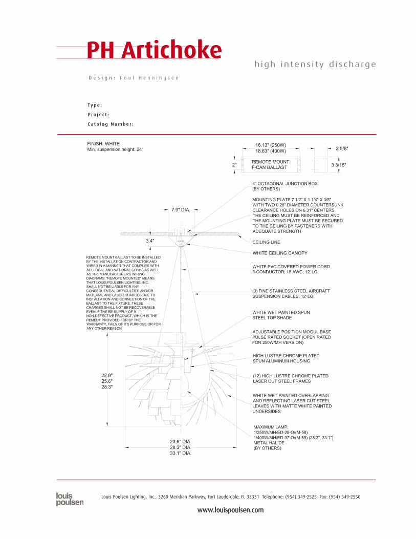
w w w . l o u i s p o u l s e n . c o m
Louis Poulsen Lighting, Inc., 3260 Meridian Parkway, Fort Lauderdale, FL 33331 Telephone: (954) 349-2525 Fax: (954) 349-2550
Ty p e :
P r o j e c t :
C a t a l o g N u m b e r :
D e s i g n : P o u l H e n n i n g s e n
PH Artichoke high intens i ty d ischarge
REMOTE MOUNT BALLAST TO BE INSTALLED BY THE INSTALLATION CONTRACTOR AND WIRED IN A MANNER THAT COMPLIES WITH ALL LOCAL AND NATIONAL CODES AS WELL AS THE MANUFACTURER'S WIRING DIAGRAMS. "REMOTE MOUNTED" MEANS THAT LOUIS POULSEN LIGHTING, INC. SHALL NOT BE LIABLE FOR ANY CONSEQUENTIAL DIFFICULTIES AND/OR MATERIAL AND LABOR CHARGES DUE TO INSTALLATION AND CONNECTION OF THE BALLAST TO THE FIXTURE. THESE CHARGES SHALL NOT BE RECOVERABLE EVEN IF THE RE-SUPPLY OF A NON-DEFECTIVE PRODUCT, WHICH IS THE REMEDY PROVIDED FOR BY THE WARRANTY, FAILS OF ITS PURPOSE OR FOR ANY OTHER REASON.
FINISH: WHITE Min. suspension height: 24"
WHITE WET PAINTED SPUN STEEL TOP SHADE
MAXIMUM LAMP: 1/250W/MH/ED-28-O/(M-58) 1/400W/MH/ED-37-O/(M-59) (28.3", 33.1")METAL HALIDE (BY OTHERS)
(12) HIGH LUSTRE CHROME PLATED LASER CUT STEEL FRAMES
HIGH LUSTRE CHROME PLATED SPUN ALUMINUM HOUSING
ADJUSTABLE POSITION MOGUL BASE PULSE RATED SOCKET (OPEN RATED FOR 250W/MH VERSION)
WHITE WET PAINTED OVERLAPPING AND REFLECTING LASER CUT STEEL LEAVES WITH MATTE WHITE PAINTED UNDERSIDES
MOUNTING PLATE 7 1/2" X 1 1/4" X 3/8" WITH TWO 0.28" DIAMETER COUNTERSUNK CLEARANCE HOLES ON 6.31" CENTERS. THE CEILING MUST BE REINFORCED AND THE MOUNTING PLATE MUST BE SECURED TO THE CEILING BY FASTENERS WITH ADEQUATE STRENGTH
WHITE PVC COVERED POWER CORD 3-CONDUCTOR; 18 AWG; 12' LG.
(3) FINE STAINLESS STEEL AI RCRAFT SUSPENSION CABLES; 12' LG.
4" OCTAGONAL JUNCTION BOX (BY OTHERS)
WHITE CEILING CANOPY
CEILING LINE
REMOTE MOUNT F-CAN BALLAST
22.8" 25.6" 28.3"
23.6" DIA. 28.3" DIA. 33.1" DIA.
7.9" DIA.
3.4"
16.13" (250W) 18.63" (400W)
2" 3 3/16"
2 5/8"
pendants
PH Artichoke
w w w . l o u i s p o u l s e n . c o m
Louis Poulsen Lighting, Inc., 3260 Meridian Parkway, Fort Lauderdale, FL 33331 Telephone: (954) 349-2525 Fax: (954) 349-2550
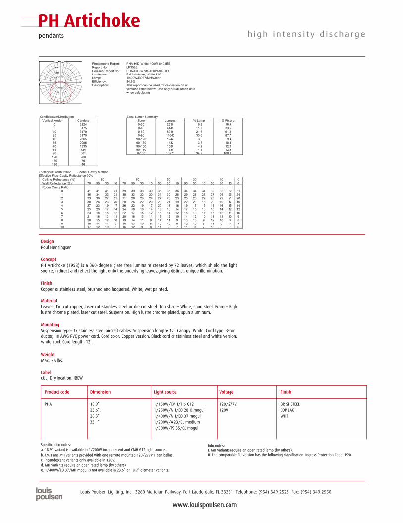
Photometric Report: PHA-HID-White-400W-840.IES Report No.: LP3583 Poulsen Report No.: PHA-HID-White-400W-840.IES Luminaire: PH Artichoke, White-840 Lamp: 1/400W/ED37/MH/Clear Efficiency: 34.9% Description: This report can be used for calculation on all
versions listed below. Use only actual lumen data when calculating
Candlepower Distribution Zonal Lumen Summary Vertical Angle Candela Zone Lumens % Lamp % Fixture
0 3224 0-30 2638 6.9 19.9 5 3175 0-40 4445 11.7 33.5 10 3179 0-60 8215 21.6 61.9 25 3170 0-90 11640 30.6 87.7 40 2665 90-120 1244 3.3 9.4 55 2095 90-130 1432 3.8 10.8 70 1335 90-150 1588 4.2 12.0 85 724 90-180 1638 4.3 12.3 90 581 0-180 13278 34.9 100.0 120 280 150 76 180 46
Coe�cients of Utilization - Zonal Cavity Method Effective Floor Cavity Reflectance 20%
Ceiling Reflectance (%) 80 70 50 30 10 0 Wall Reflectance (%) 70 50 30 10 70 50 30 10 50 30 10 50 30 10 50 30 10 0 Room Cavity Ratio
0 41 41 41 41 39 39 39 39 36 36 36 34 34 34 32 32 32 31 1 36 34 33 31 35 33 32 30 31 30 28 29 28 27 27 26 25 24 2 33 30 27 25 31 28 26 24 27 25 23 25 23 22 23 22 21 20 3 30 26 23 20 28 26 22 20 23 21 19 22 20 18 20 19 17 16 4 27 23 19 17 26 22 19 17 20 18 16 19 17 15 18 16 15 14 5 25 20 17 14 24 19 16 14 18 16 14 17 15 13 16 14 12 12 6 23 18 15 12 22 17 15 12 16 14 12 15 13 11 15 12 11 10 7 21 16 13 11 20 16 13 11 15 12 10 14 12 10 13 11 10 9 8 20 15 12 10 19 14 11 9 14 11 9 13 10 9 12 10 9 8 9 18 14 11 9 18 13 10 8 12 10 8 12 10 8 11 9 8 7 10 17 12 10 8 16 12 9 8 11 9 7 11 9 7 10 8 7 6
high intens i ty d ischarge
DesignPoul Henningsen
ConceptPH Artichoke (1958) is a 360-degree glare free luminaire created by 72 leaves, which shield the lightsource, redirect and reflect the light onto the underlying leaves,giving distinct, unique illumination.
FinishCopper or stainless steel, brushed and lacquered. White, wet painted.
MaterialLeaves: Die cut copper, laser cut stainless steel or die cut steel. Top shade: White, spun steel. Frame: Highlustre chrome plated, laser cut steel. Suspension: High lustre chrome plated, spun aluminum.
MountingSuspension type: 3x stainless steel aircraft cables. Suspension length: 12’. Canopy: White. Cord type: 3-conductor, 18 AWG PVC power cord. Cord color: Copper version: Black cord or stainless steel and white version:white cord. Cord length: 12’.
WeightMax. 55 lbs.
LabelcUL, Dry location. IBEW.
Product code Dimension Light source Voltage Finish
PHA 18.9” 1/150W/CMH/T-6 G12 120/277V BR ST STEEL 23.6”. 1/250W/MH/ED-28-O mogul 120V COP LAC 28.3” 1/400W/MH/ED-37 mogul WHT 33.1” 1/200W/A-23/CL medium
1/500W/PS-35/CL mogul
Info notes:I. MH variants require an open rated lamp (by others).II. The comparable EU version has the following classification: Ingress Protection Code: IP20.
a. 18.9” variant is available in 1/200W incandescent and CMH G12 light sources.b. CMH and MH variants provided with one remote mounted 120/277V F-can ballast.c. Incandescent variants only available in 120V.d. MH variants require an open rated lamp (by others)e. 1/400W/ED-37/MH mogul is not available in 23.6” or 18.9” diameter variants.
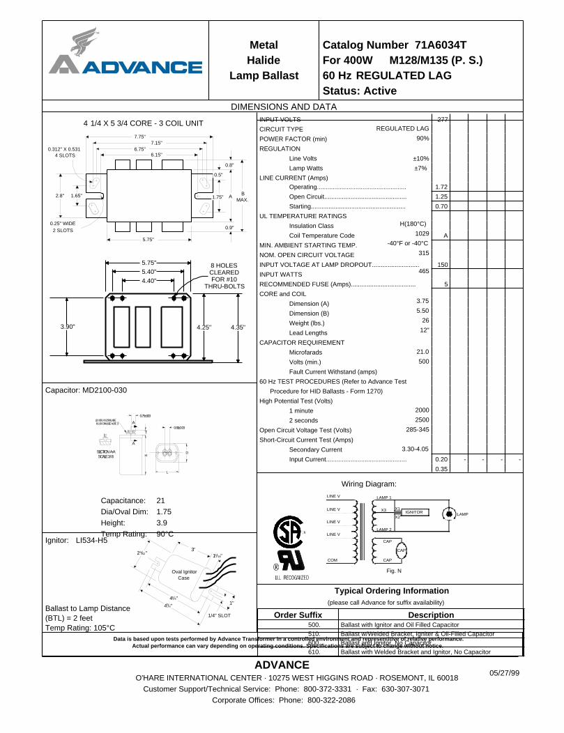
Metal
Halide
Lamp Ballast
Catalog Number 71A6034T
For 400W M128/M135 (P. S.)
60 Hz REGULATED LAG
Status: Active
DIMENSIONS AND DATA
1.65"
7.75"
7.15"
B
MAX.
0.8"
0.25" WIDE
2 SLOTS
A
0.9"
1.75"
0.5"
2.8"
6.75"6.15"
0.312" X 0.531
4 SLOTS
5.75"
4 1/4 X 5 3/4 CORE - 3 COIL UNIT
3.90"
5.75"
5.40"
4.35"4.25"
8 HOLESCLEAREDFOR #10
THRU-BOLTS4.40"
Capacitor: MD2100-030
A
A
T0.81±0.03
0.75±0.03
HD
L
SCALE3/8SECTIONA-A
(2) 0.031X0.250BLADE.PLUSFORK(SEENOTE7)
Capacitance: 21
Dia/Oval Dim: 1.75
Height: 3.9
Temp Rating: 90°C
1"
1/4" SLOT
43/4"
41/4"
25/32"3"
15/16"
Oval Ignitor
Case
Ballast to Lamp Distance
(BTL) = 2 feet
Temp Rating: 105°C
Ignitor: LI534-H5
Data is based upon tests performed by Advance Transformer in a controlled environment and representitive of relative performance.Actual performance can vary depending on operating conditions. Specifications are subject to change without notice.
ADVANCEO'HARE INTERNATIONAL CENTER · 10275 WEST HIGGINS ROAD · ROSEMONT, IL 60018
Customer Support/Technical Service: Phone: 800-372-3331 · Fax: 630-307-3071
Corporate Offices: Phone: 800-322-2086
INPUT VOLTS 277
CIRCUIT TYPE
POWER FACTOR (min)
REGULATION
Line Volts
Lamp Watts
LINE CURRENT (Amps)
Operating................................................... 1.72
Open Circuit............................................... 1.25
Starting...................................................... 0.70
UL TEMPERATURE RATINGS
Insulation Class
Coil Temperature Code A
MIN. AMBIENT STARTING TEMP.
NOM. OPEN CIRCUIT VOLTAGE
INPUT VOLTAGE AT LAMP DROPOUT........................... 150
INPUT WATTS
RECOMMENDED FUSE (Amps)..................................... 5
CORE and COIL
Dimension (A)
Dimension (B)
Weight (lbs.)
Lead Lengths
CAPACITOR REQUIREMENT
Microfarads
Volts (min.)
Fault Current Withstand (amps)
60 Hz TEST PROCEDURES (Refer to Advance Test
Procedure for HID Ballasts - Form 1270)
High Potential Test (Volts)
1 minute
2 seconds
Open Circuit Voltage Test (Volts)
Short-Circuit Current Test (Amps)
Secondary Current
Input Current.............................................. 0.20 - - - -
0.35
REGULATED LAG
90%
±10%
±7%
H(180°C)
1029
-40°F or -40°C
315
465
3.75
5.50
26
12"
21.0
500
2000
2500
285-345
3.30-4.05
Wiring Diagram:
Fig. N
LAMP 1
CAP
LAMP
COM
LINE V
LINE V
LINE V
IGNITORX1X3
X2
LINE V
CAP
CAP
LAMP 2
Typical Ordering Information
(please call Advance for suffix availability)
Order Suffix Description 500. Ballast with Ignitor and Oil Filled Capacitor
510. Ballast w/Welded Bracket, Igniter & Oil-Filled Capacitor
600. Ballast and Ignitor, No Capacitor
610. Ballast with Welded Bracket and Ignitor, No Capacitor
05/27/99
™
JOB NAME
TYPE
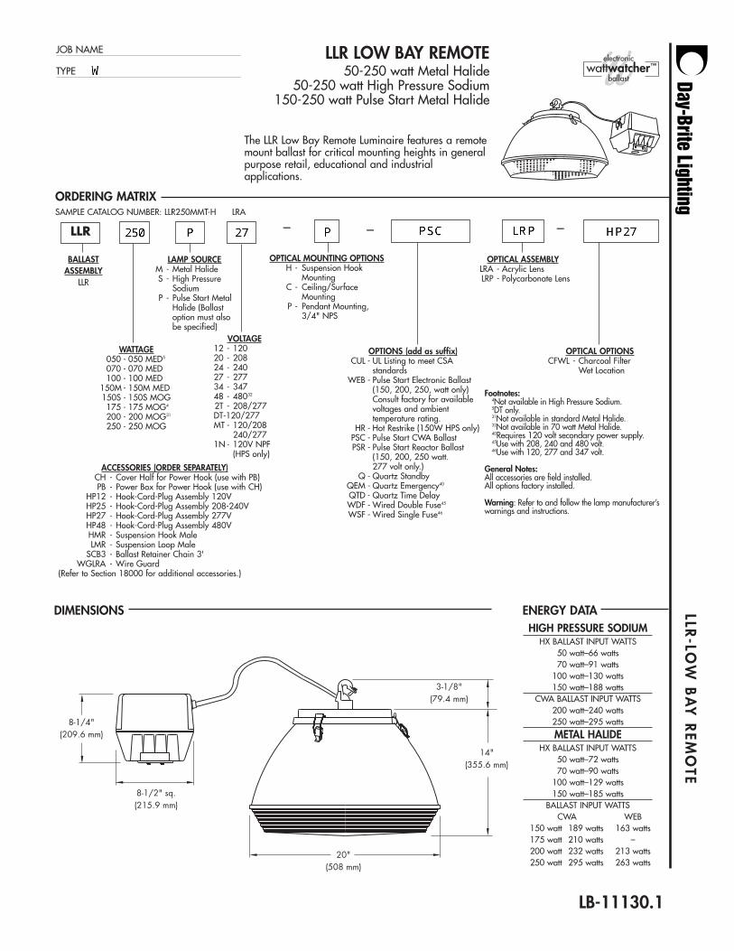
LLR LOW BAY REMOTE 50-250 watt Metal Halide
50-250 watt High Pressure Sodium150-250 watt Pulse Start Metal Halide
ORDERING MATRIX
BALLASTASSEMBLY
LLR
LAMP SOURCEM - Metal HalideS - High Pressure
SodiumP - Pulse Start Metal
Halide (Ballast option must also be specified)
– –
LLR-LO
W B
AY
REM
OTE
OPTICAL MOUNTING OPTIONSH - Suspension Hook
MountingC - Ceiling/Surface
MountingP - Pendant Mounting,
3/4" NPS
SAMPLE CATALOG NUMBER: LLR250MMT-H LRA
DIMENSIONS ENERGY DATA
The LLR Low Bay Remote Luminaire features a remotemount ballast for critical mounting heights in generalpurpose retail, educational and industrialapplications.
(508 mm)20"
8-1/2" sq.(215.9 mm)
8-1/4"(209.6 mm)
3-1/8"(79.4 mm)
14"(355.6 mm)
LLR
ACCESSORIES (ORDER SEPARATELY)CH - Cover Half for Power Hook (use with PB)PB - Power Box for Power Hook (use with CH)
HP12 - Hook-Cord-Plug Assembly 120VHP25 - Hook-Cord-Plug Assembly 208-240VHP27 - Hook-Cord-Plug Assembly 277VHP48 - Hook-Cord-Plug Assembly 480VHMR - Suspension Hook MaleLMR - Suspension Loop Male
SCB3 - Ballast Retainer Chain 3'WGLRA - Wire Guard
(Refer to Section 18000 for additional accessories.)
LB-11130.1
–
OPTICAL OPTIONSCFWL - Charcoal Filter
Wet Location
OPTICAL ASSEMBLYLRA - Acrylic LensLRP - Polycarbonate Lens
HIGH PRESSURE SODIUMHX BALLAST INPUT WATTS
50 watt–66 watts70 watt–91 watts
100 watt–130 watts150 watt–188 watts
CWA BALLAST INPUT WATTS200 watt–240 watts250 watt–295 watts
METAL HALIDEHX BALLAST INPUT WATTS
50 watt–72 watts70 watt–90 watts
100 watt–129 watts150 watt–185 watts
BALLAST INPUT WATTSCWA WEB
150 watt 189 watts 163 watts175 watt 210 watts –200 watt 232 watts 213 watts250 watt 295 watts 263 watts
WATTAGE050 - 050 MED5
070 - 070 MED100 - 100 MED
150M - 150M MED150S - 150S MOG175 - 175 MOG4
200 - 200 MOG31
250 - 250 MOG
VOLTAGE12 - 12020 - 20824 - 24027 - 27734 - 34748 - 48032
2T - 208/277DT-120/277MT - 120/208
240/2771N - 120V NPF
(HPS only)
OPTIONS (add as suffix)CUL - UL Listing to meet CSA
standardsWEB - Pulse Start Electronic Ballast
(150, 200, 250, watt only) Consult factory for available voltages and ambient temperature rating.
HR - Hot Restrike (150W HPS only)PSC - Pulse Start CWA BallastPSR - Pulse Start Reactor Ballast
(150, 200, 250 watt. 277 volt only.)
Q - Quartz StandbyQEM - Quartz Emergency40
QTD - Quartz Time DelayWDF - Wired Double Fuse45
WSF - Wired Single Fuse46
Footnotes:4Not available in High Pressure Sodium.5DT only.31Not available in standard Metal Halide.32Not available in 70 watt Metal Halide.40Requires 120 volt secondary power supply.45Use with 208, 240 and 480 volt.46Use with 120, 277 and 347 volt.
General Notes:All accessories are field installed.All options factory installed.
Warning: Refer to and follow the lamp manufacturer’swarnings and instructions.
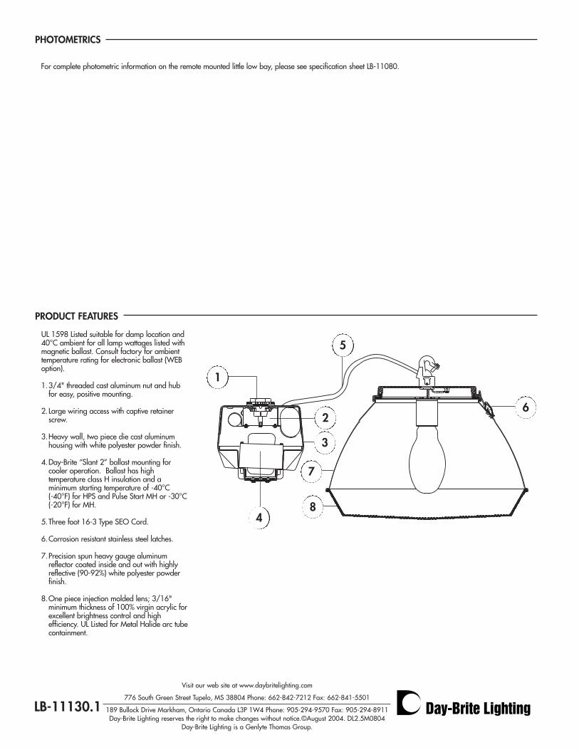
PHOTOMETRICS
LB-11130.1
PRODUCT FEATURES
UL 1598 Listed suitable for damp location and40°C ambient for all lamp wattages listed withmagnetic ballast. Consult factory for ambienttemperature rating for electronic ballast (WEBoption).
1.3/4" threaded cast aluminum nut and hub for easy, positive mounting.
2.Large wiring access with captive retainer screw.
3.Heavy wall, two piece die cast aluminum housing with white polyester powder finish.
4.Day-Brite “Slant 2” ballast mounting for cooler operation. Ballast has high temperature class H insulation and a minimum starting temperature of -40°C(-40°F) for HPS and Pulse Start MH or -30°C(-20°F) for MH.
5.Three foot 16-3 Type SEO Cord.
6.Corrosion resistant stainless steel latches.
7.Precision spun heavy gauge aluminum reflector coated inside and out with highly reflective (90-92%) white polyester powder finish.
8.One piece injection molded lens; 3/16" minimum thickness of 100% virgin acrylic forexcellent brightness control and high efficiency. UL Listed for Metal Halide arc tubecontainment.
1
26
3
7
5
4
Visit our web site at www.daybritelighting.com
776 South Green Street Tupelo, MS 38804 Phone: 662-842-7212 Fax: 662-841-5501
189 Bullock Drive Markham, Ontario Canada L3P 1W4 Phone: 905-294-9570 Fax: 905-294-8911Day-Brite Lighting reserves the right to make changes without notice.©August 2004. DL2.5M0804
Day-Brite Lighting is a Genlyte Thomas Group.
8
For complete photometric information on the remote mounted little low bay, please see specification sheet LB-11080.
Metal
Halide
Lamp Ballast
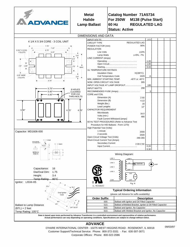
Catalog Number 71A5734
For 250W M138 (Pulse Start)
60 Hz REGULATED LAG
Status: Active
DIMENSIONS AND DATA
1.65"
7.75"
7.15"
B
MAX.
0.8"
0.25" WIDE
2 SLOTS
A
0.9"
1.75"
0.5"
2.8"
6.75"6.15"
0.312" X 0.531
4 SLOTS
5.75"
4 1/4 X 5 3/4 CORE - 3 COIL UNIT
3.90"
5.75"
5.40"
4.35"4.25"
8 HOLESCLEAREDFOR #10
THRU-BOLTS4.40"
Capacitor: MD1606-000
A
A
T0.81±0.03
0.75±0.03
HD
L
SCALE3/8SECTIONA-A
(2) 0.031X0.250BLADE.PLUSFORK(SEENOTE7)
Capacitance: 16
Dia/Oval Dim: 1.75
Height: 3.4
Temp Rating: 90°C
1"
1/4" SLOT
43/4"
41/4"
25/32"3"
15/16"
Oval Ignitor
Case
Ballast to Lamp Distance
(BTL) = 2 feet
Temp Rating: 105°C
Ignitor: LI534-H5
Data is based upon tests performed by Advance Transformer in a controlled environment and representitive of relative performance.Actual performance can vary depending on operating conditions. Specifications are subject to change without notice.
ADVANCEO'HARE INTERNATIONAL CENTER · 10275 WEST HIGGINS ROAD · ROSEMONT, IL 60018
Customer Support/Technical Service: Phone: 800-372-3331 · Fax: 630-307-3071
Corporate Offices: Phone: 800-322-2086
INPUT VOLTS 277
CIRCUIT TYPE
POWER FACTOR (min)
REGULATION
Line Volts
Lamp Watts
LINE CURRENT (Amps)
Operating................................................... 1.20
Open Circuit............................................... 1.00
Starting...................................................... 0.43
UL TEMPERATURE RATINGS
Insulation Class
Coil Temperature Code A
MIN. AMBIENT STARTING TEMP.
NOM. OPEN CIRCUIT VOLTAGE
INPUT VOLTAGE AT LAMP DROPOUT........................... 195
INPUT WATTS
RECOMMENDED FUSE (Amps)..................................... 3
CORE and COIL
Dimension (A)
Dimension (B)
Weight (lbs.)
Lead Lengths
CAPACITOR REQUIREMENT
Microfarads
Volts (min.)
Fault Current Withstand (amps)
60 Hz TEST PROCEDURES (Refer to Advance Test
Procedure for HID Ballasts - Form 1270)
High Potential Test (Volts)
1 minute
2 seconds
Open Circuit Voltage Test (Volts)
Short-Circuit Current Test (Amps)
Secondary Current
Input Current.............................................. 0.20 - - - -
0.30
REGULATED LAG
90%
±10%
±+5%, -7%
H(180°C)
1029
-40°F or -40°C
305
298
2.50
4.13
16
12"
16.0
480
2000
2500
290-355
2.00-2.50
Wiring Diagram:
Fig. N
LAMP 1
CAP
LAMP
COM
LINE V
LINE V
LINE V
IGNITORX1X3
X2
LINE V
CAP
CAP
LAMP 2
Typical Ordering Information
(please call Advance for suffix availability)
Order Suffix Description 500. Ballast with Ignitor and Oil Filled Capacitor
510. Ballast w/Welded Bracket, Igniter & Oil-Filled Capacitor
600. Ballast and Ignitor, No Capacitor
610. Ballast with Welded Bracket and Ignitor, No Capacitor
09/03/97


![2009 Natural and Agricultural Sciences] Part 1] Natural Sciences] … · 2016. 10. 21. · Faculty of Natural and Agricultural Sciences Year Book 2009 Part 1: Natural Sciences: Undergraduate](https://img.pdfslide.us/doc/110x75/60d6e037894e3569c43ddd1e/2009-natural-and-agricultural-sciences-part-1-natural-sciences-2016-10-21.jpg)