Embed Size (px)
Citation preview
UCGE Reports Number 20161
Department of Geomatics Engineering
A Java-Based Wireless Framework for Location-Based Services Applications
(URL: http://www.geomatics.ucalgary.ca/links/GradTheses.html)
by
Zhe Liu
June 2002
THE UNIVERSITY OF CALGARY
A Java-Based Wireless Framework for Location-Based Services Applications
by
Zhe Liu
A THESIS
SUBMITTED TO THE FACULTY OF GRADUATE STUDIES
IN PARTIAL FULFILLMENT OF THE REQUIREMENTS FOR THE
DEGREE OF MASTERS OF SCIENCE
DEPARTMENT OF GEOMATICS ENGINEERING
CALGARY, ALBERTA
June 30, 2002
© Zhe Liu 2002
ii
PREFACE
This is an unaltered version of the author�s Master of Science thesis of the same title.
This thesis was accepted by the Faculty of Graduate Studies in July, 2002.
The faculty supervisor for this work was Dr. Yang Gao of The University of Calgary.
Members of the examining committee were Dr. Yang Gao, Dr. Naser EI-Sheimy, and Dr.
Ron Wong all of The University of Calgary.
iv
ABSTRACT
Location Based Services (LBS) applications are a category of new emerging and fast
growing applications. Potential LBS applications are enormous including vehicle
navigation, fleet management, real estate, and travel services. Objected-Oriented (OO)
application framework technology is an efficient and easy-to-use tool for application
developers to promote software reuse. Moreover, OO application framework technology
has its unique advantage in support of the development of wireless communication
software. The framework can also enhance the maintenance, readability and modifiability
of the developed software. To facilitate the LBS application developers to take
advantages of the fast-evolving wireless communication technologies, a wireless
framework has been developed to host some of the most popular wireless technologies
available in the market. The wireless framework, based on an open structure, which
already supports wireless modems and wireless Internet, is easy and friendly to
incorporate new technologies into existing infrastructures. The wireless framework
employs a pure Java solution to increase the platform-independency and life span of the
software. The developed wireless framework has been applied to the development of two
different prototype systems, namely, a Wireless Internet-Based Real-Time Kinematic
GPS Positioning System and a Mobile Equipment Management System. The test results
have indicated that the developed wireless framework can support LBS applications with
critical real-time and security requirements.

v
ACKNOWLEDGMENT
I wish to acknowledge and thank all the individuals and groups who contributed to my
graduate work. Without their support, this thesis would not have been possible for me.
First and foremost, I would like to thank and express my sincere appreciation to my
graduate studies supervisor, Dr. Yang Gao for his continuous support and genuine
interest during my graduate studies. He has always shown faith in my abilities by sharing
responsibilities and opportunities with me.
I would also like to thank the many professors, students, and staff in the Department of
Geomatics Engineering who have made my time fruitful and enjoyable.
A special thanks to my dear wife, Nan, who supported me tremendously throughout my
career path and the completion of this thesis. Many thanks go to my parents and my sister
for their support, encouragement and patience.
vi
TABLE OF CONTENTS
THE UNIVERSITY OF CALGARY .............................................................................. I
PREFACE ................................................................................................................ II
APPROVAL PAGE........................................................................................................ III
ABSTRACT .................................................................................................................IV
ACKNOWLEDGMENT.................................................................................................. V
TABLE OF CONTENTS................................................................................................VI
LIST OF TABLES ..........................................................................................................IX
LIST OF FIGURES ......................................................................................................... X
NOTATION ............................................................................................................... XII
CHAPTER 1: INTRODUCTION.................................................................................... 1 1.1 BACKGROUND......................................................................................................... 1 1.2 OBJECTIVES ............................................................................................................ 8 1.3 THESIS OUTLINE ..................................................................................................... 9
CHAPTER 2: LOCATION BASED SERVICES......................................................... 11 2.1 CONCEPT OF LOCATION BASED SERVICES ............................................................ 11 2.2 LBS SYSTEM ARCHITECTURE............................................................................... 17
CHAPTER 3: WIRELESS COMMUNICATION ....................................................... 24 3.1 INTRODUCTION TO CURRENT WIRELESS COMMUNICATION TECHNOLOGIES.......... 25
3.1.1 Terrestrial Wireless Communication ............................................................ 25 3.1.2 Satellite Wireless Communication ................................................................ 29
3.2 WIRELESS COMMUNICATION METHODS FOR LBS APPLICATIONS ........................ 33 3.2.1 CDPD ............................................................................................................ 34 3.2.2 GSM .............................................................................................................. 37 3.2.3 Radio Modem in UHF Commercial Band..................................................... 40 3.2.4 Dedicated Mobile Data Network................................................................... 42
CHAPTER 4: OBJECT-ORIENTED APPLICATION FRAMEWORK ................. 45 4.1 CONCEPT OF OO APPLICATION FRAMEWORK....................................................... 46 4.2 STRENGTHS AND WEAKNESSES OF OO APPLICATION FRAMEWORKS.................... 49 4.3 OO TECHNOLOGY AND SOFTWARE REUSABILITY................................................. 53
4.3.1 Software Reusability ..................................................................................... 53 4.3.2 Object-Orientation Methodology .................................................................. 54
vii
4.3.3 Software Reusability and Object Orientation................................................ 57 4.3.4 Other Benefits of Object Orientation ............................................................ 61
4.4 OO APPLICATION FRAMEWORK AND SOFTWARE REUSABILITY ........................... 63 4.4.1 Frameworks and Components ....................................................................... 63 4.4.2 Frameworks and Templates .......................................................................... 65 4.4.3 Frameworks and Patterns .............................................................................. 65 4.4.4 Framework: Middle of Reuse........................................................................ 66
CHAPTER 5: DEVELOPMENT OF A WIRELESS FRAMEWORK FOR LBS APPLICATIONS............................................................................................................. 67
5.1 OBJECT-ORIENTED APPLICATION FRAMEWORK DESIGN AND METHODOLOGY..... 67 5.1.1 Basis of Framework Design: Abstract Class and Interface........................... 67 5.1.2 Framework Architecture ............................................................................... 69 5.1.3 Framework Design Methodology: Blackbox Design or Whitebox Design .. 70 5.1.4 Programming Tool for Framework: Java ...................................................... 72
5.2 OBJECTIFYING WIRELESS COMMUNICATION OF LBS............................................ 75 5.2.1 Object-Oriented technology and Wireless Communication.......................... 75 5.2.2 Breaking Wireless Communication of LBS into Objects and Their
Interaction...................................................................................................... 76 5.3 A FRAMEWORK FOR WIRELESS COMMUNICATION OF LBS................................... 81
5.3.1 Application Domain Analysis ....................................................................... 81 5.3.2 Wireless Framework Design: Internal Interfaces and Abstract Classes........ 83
5.4 THE STRUCTURE AND GRAPHICAL USER INTERFACES.................................................... 91 5.4.1 Structures Represented by Circuit Board ...................................................... 91 5.4.2 Graphical User Interfaces.............................................................................. 92
CHAPTER 6: APPLICATION AND TEST RESULTS: MOBILE EQUIPMENT MANAGEMENT........................................ 97
6.1 MOBILE EQUIPMENT MANAGEMENT..................................................................... 97 6.1.1 Concept of MEMS ........................................................................................ 98 6.1.2 A Prototype of MEMS ................................................................................ 101
6.2 IMPLEMENTATION OF WIRELESS FRAMEWORK FOR MEMS................................ 103 6.3 FIELD TEST AND RESULTS .................................................................................. 107
6.3.1 Test Details and Results of Radio-Based MEMS ....................................... 107 6.3.2 Test Details and Results of CDPD-Based MEMS ...................................... 109
CHAPTER 7: APPLICATION AND TEST RESULTS: WIRELESS INTERNET-BASED RTK GPS POSITIONING....... 112
7.1 CONCEPT OF WIRELESS INTERNET-BASED RTK GPS POSITIONING ................... 112 7.2 IMPLEMENTATION OF WIRELESS FRAMEWORK FOR INTERNET-BASED RTK....... 115 7.3 FIELD TESTS AND RESULTS................................................................................. 118
7.3.1 Field Test Results of Wireless Internet-based RTK GPS Positioning without RTCM Messages Compression...................................................... 118
7.3.2 Field Test Results of Wireless Internet-based RTK GPS Positioning with RTCM Messages Compression........................................................... 125
viii
CHAPTER 8: CONCLUSIONS AND RECOMMENDATIONS ............................. 128 8.1 CONCLUSIONS..................................................................................................... 128 8.2 RECOMMENDATIONS........................................................................................... 131
REFERENCES.............................................................................................................. 133
ix
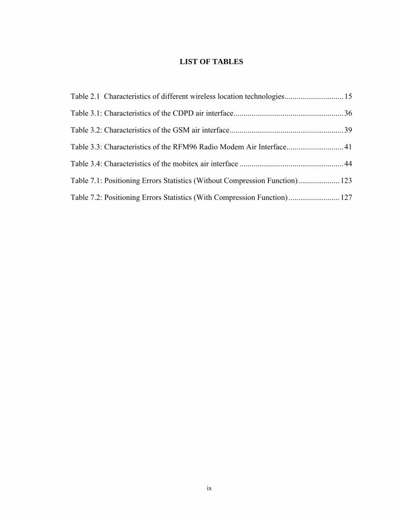
LIST OF TABLES
Table 2.1 Characteristics of different wireless location technologies.............................. 15
Table 3.1: Characteristics of the CDPD air interface........................................................ 36
Table 3.2: Characteristics of the GSM air interface.......................................................... 39
Table 3.3: Characteristics of the RFM96 Radio Modem Air Interface............................. 41
Table 3.4: Characteristics of the mobitex air interface ..................................................... 44
Table 7.1: Positioning Errors Statistics (Without Compression Function)..................... 123
Table 7.2: Positioning Errors Statistics (With Compression Function) .......................... 127
x
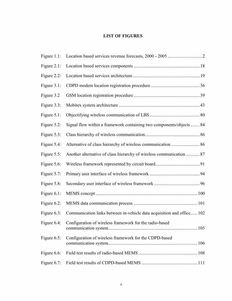
LIST OF FIGURES
Figure 1.1: Location based services revenue forecasts, 2000 - 2005 .............................. 2
Figure 2.1: Location based services components .......................................................... 18
Figure 2.2: Location based services architecture........................................................... 19
Figure 3.1: CDPD modem location registration procedure ........................................... 36
Figure 3.2 GSM location registration procedure .......................................................... 39
Figure 3.3: Mobitex system architecture ....................................................................... 43
Figure 5.1: Objectifying wireless communication of LBS............................................ 80
Figure 5.2: Signal flow within a framework containing two components/objects ........ 84
Figure 5.3: Class hierarchy of wireless communication................................................ 86
Figure 5.4: Alternative of class hierarchy of wireless communication ......................... 86
Figure 5.5: Another alternative of class hierarchy of wireless communication ............ 87
Figure 5.6: Wireless framework represented by circuit board....................................... 91
Figure 5.7: Primary user interface of wireless framework ............................................ 94
Figure 5.8: Secondary user interface of wireless framework ........................................ 96
Figure 6.1: MEMS concept ......................................................................................... 100
Figure 6.2: MEMS data communication process ........................................................ 101
Figure 6.3: Communication links between in-vehicle data acquisition and office...... 102
Figure 6.4: Configuration of wireless framework for the radio-based communication system.............................................................................. 105
Figure 6.5: Configuration of wireless framework for the CDPD-based communication system.............................................................................. 106
Figure 6.6: Field test results of radio-based MEMS.................................................... 108
Figure 6.7: Field test results of CDPD-based MEMS ................................................. 111
xi
Figure 7.1: Configuration of wireless framework for RTK with compression function ..................................................................................................... 117
Figure 7.2: Round trip time latency results ................................................................. 122
Figure 7.3: PDOP values and the number of satellites ................................................ 122
Figure 7.4: RTK results without compression function............................................... 123
Figure 7.5: RTK positioning status ............................................................................. 124
Figure 7.6: UDP packets received by the rover receiver ............................................. 124
Figure 7.7: Round trip time latency results ................................................................. 126
Figure 7.8: PDOP values and the number of satellites ................................................ 126
Figure 7.9: RTK results with compression function.................................................... 127
xii
NOTATION
1G The 1st Generation of telecommunication
2G The 2nd Generation of telecommunication
2.5G Technologies between the 2nd and 3rd Generations of telecommunication
3G The 3rd Generation of telecommunication
AGPS Assisted Global Positioning Satellite System
AMPS Advance Mobile Phone Service
AOA Angle Of Arrival
API Application Program Interface
CDMA Code Division Multiple Access
CDPD Cellular Digital Packet Data
COO Cell Of Origin
CORBA Common Object Request Broker Architecture
CPU Central Processing Unit
DBMS Database Management System
DCOM Distributed Common Object Model
DGPS Differential Global Positioning Satellite System
DOD Department of Defense
DOP Dilution Of Precision
DS-CDMA Direct-Sequence Code Division Multiple Access
E911 Enhanced 911 Services
EDGE Enhanced Data GSM Environment
xiii
E-OTD Enhanced Offset Time Division
FCC Federal Communication Commission
GEO Geostationary Earth Orbit
GIS Geographic Information System
GPRS General Packet Radio Services
GPS Global Positioning Satellite System
GSM Global System for Mobile
GUI Graphical User Interface
HLR Home Location Register
HSCSD High-Speed Circuit-Switched Data
HTML Hypertext Markup Language
HTTP Hypertext Transfer Protocol
IMT International Mobile Telephony
IN Intelligent Network
IPR Intellectual Property Right
ITU International Telecommunication Union
J2ME Java 2 Platform, Micro Edition
LAN Local Area Network
LBS Location Based Services
LEO Low Earth Orbit
LIF Location Inter-operability Forum
LOS Line Of Sight
MEMS Mobile Equipment Management System
xiv
MEO Medium Earth Orbit
MFC Microsoft Foundation Classes
MD-IS Mobile Data Intermediate System
MS Mobile Station
MSAT Mobile Satellite System
MVC Model/View/Controller
NMC Network Management Center
NMEA National Marine Electronics Association
OGC Open GIS Consortium
OLE Object Linking and Embedding
OMG Object Management Group
OO Object-Oriented
OOD Object-Oriented Design
OOP Object-Oriented Programming
OS Operating System
OSI Open Systems Interconnection
PC Personal Computer
PCS Personal Communications Services
PDA Personal Digital Assistant
PDOP Position Dilution of Precision
PSDN Public Switched Data Network
RMI Remote Method Invocation
RTCM Radio Technical Commission for Maritime Services
xv
RTK Real-Time Kinematic GPS Positioning
RTT Radio Transmission Technologies
SA Selective Availability
SIM Subscriber Identity Module
SMS Short Message Services
SOAP Simple Object Access Protocol
TCP/IP Transmission Control Protocol/Internet Protocol
TOA Time Of Arrival
UDP/IP User Datagram Protocol/Internet Protocol
UHF Ultra High Frequency
UMTS Universal Mobile Telephone System
VHF Very High Frequency
VLR Visiting Location Register
VLSI Very Large Scale Integration
WAP Wireless Application Protocol
WCDMA Wideband Code Division Multiple Access
1
1
Chapter 1
Introduction
1.1 Background
A category of applications, which is known variously as Location-Based Services (LBS),
Location Commerce (or L-commerce), mobile commerce, mobile location services,
wireless location, and similar terms, is now emerging rapidly in the Geospatial
Information marketplace. By any name, the purpose and character of LBS remains the
same: employing accurate real-time position information of users to connect them to
nearby points of interest (such as retail businesses, public facilities, or travel
destinations), to advise them of current conditions (such as traffic and weather), or to
provide routing and tracking services. For example, a person at shopping mall calls for
information on the nearest restaurant with an economy budget. He/She needs only names
and addresses of those restaurants that are within his reach, say within one square-
kilometer, out of the database of, say 2000 restaurants in the city spread over 1600 square
kilometers [Prasad, 2001]. At the intersection of Web, wireless communication and
Geographic Information System (GIS) technologies, Location Based Services are aimed
at giving everyone the ability to exploit location information anywhere, anytime, and on
any device. LBS are expected to create a new global market ─ in both business-to-
business and business-to-consumer services ─ with annual revenues well into double-
digit billions of dollars within a few years [Gibbons, 2001].
2
2
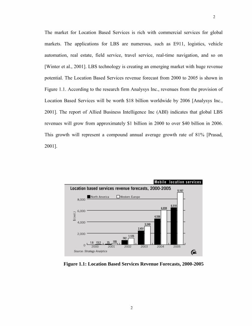
The market for Location Based Services is rich with commercial services for global
markets. The applications for LBS are numerous, such as E911, logistics, vehicle
automation, real estate, field service, travel service, real-time navigation, and so on
[Winter et al., 2001]. LBS technology is creating an emerging market with huge revenue
potential. The Location Based Services revenue forecast from 2000 to 2005 is shown in
Figure 1.1. According to the research firm Analysys Inc., revenues from the provision of
Location Based Services will be worth $18 billion worldwide by 2006 [Analysys Inc.,
2001]. The report of Allied Business Intelligence Inc (ABI) indicates that global LBS
revenues will grow from approximately $1 billion in 2000 to over $40 billion in 2006.
This growth will represent a compound annual average growth rate of 81% [Prasad,
2001].
Figure 1.1: Location Based Services Revenue Forecasts, 2000-2005
3
3
The explosion of LBS should be attributed to the revolutionary advancements in Global
Positioning Satellite System (GPS), distributed GIS, handheld client device, database,
wireless network, communication protocol and the Internet in recent years. With the
integration of these technologies, Location Based Services open the door to opportunities
in virtually every discipline of every industry [Autodesk, 2000]. Among all the foresaid
technologies, wireless communication is regarded as key for LBS, since the essential of
LBS is using location to deliver targeted applications to users, most of which are mobile,
at their moment of need [Autodesk, 2000].
The explosion of LBS results in fast increasing requirements for software. To take
wireless communication in LBS as an example, more than 200 terrestrial wireless service
providers compete to supply communications services to businesses and consumers in the
United States [Fall Creek Consultants, 1998]. The diversification of the market
significantly increases requirements for software. Moreover, wireless communication
technologies evolve so fast that the corresponding software has to be updated frequently
to catch up with the advancements. Furthermore, the fact that it is lack of semi-custom
solutions for wireless communication in the market forces the application developers to
develop their programs from scratch. As a result of continuously increasing software
requirements, the growth of LBS applications will result in a software crisis if no action
is taken. The outcomes of a software crisis, such as lack of Highly Qualified Personnel
(HQP), increased development costs and time, and degradation of software quality, will
make the LBS application developers incompetent to respond to the market requirements.
4
4
The best solution for the software crisis up to now is to increase software reusability,
which has been demonstrated successful by practice.
The LBS wireless communication software has lots of potential for software reuse. First,
although wireless communication technologies are quite diverse, those that dominate the
markets are relatively monotonous. For example, the commercial cellular telephone
system dominates the wireless communication market, and fortunately, it can provide a
relatively cheap service for both voice and data. It is not difficult to combine only a few
popular wireless communication technologies to serve almost every type of LBS
applications. Second, the different types of wireless communication available on the
market are highly complementary to each other, and this stimulates software developers
of LBS applications to support various communication methods in their programs. For
example, Cellular Digital Packet Data (CDPD) has a much greater effective transmission
range via the widespread commercial telephone system network than by wireless radio
modem, but you need not to pay for running the wireless radio modem except the capital
investment on the modems, while CDPD will charge you a monthly fee. Moreover, in
program developers� view, most of the wireless communication methods can be
abstracted into similar user interfaces. For example, CDPD and Global System for
Mobile (GSM) currently are the two most important methods for wireless Internet. They
are quite different from each other technically, but after installation both can provide the
same interface to program developers. Program designed for one can be used for the
other without any modification. Since LBS Wireless Communication software shares a
5
5
lot of common features and supports similar user interfaces, it makes itself a perfect
target for software reuse.
Software reuse is the process of creating software systems from existing software rather
than building them from scratch. Software reuse is still an emerging discipline. It appears
in many different forms from ad-hoc reuse to systematic reuse, and from white-box reuse
to black-box reuse [Sametinger, 1997]. Traditional software reuse paradigm supports
code reuse only, which is also called white-box reuse [AMCIS, 2002]. In order to achieve
code reuse, the programmers have to study the source codes of previous software and
grasp the details. The code reuse process takes time and is far from easy since the reused
codes are possible incompatible with other codes in the new software. Traditional
software reuse paradigm does not support other forms of software reuse, such as
components, design document, and patterns. Recent advances in Object Oriented (OO)
technology and Application Framework make it possible to take full advantages of
multiple forms of software reuse, and at the same time save the work to study source
codes. The main goal of this research is to develop a framework to promote software
reuse of LBS applications by using Object-Oriented Application Framework technology,
the product of recent advances in Object Oriented (OO) technology and Application
Framework.
Object Oriented (OO) technology is a unique way of thinking about problems and their
solutions. OO attempts to break a problem into its component parts instead of tackling the
problem in a top-down and linear fashion as in traditional approaches and can
6
6
significantly improve the efficiency of software development as well as the maintenance,
reusability and modifiability of the developed software [Goraj, 1999]. OO is suitable for
LBS wireless communication software development. Different types of wireless
communication such as Radio pair, CDPD, GSM, Internet, Compression, Encryption are
treated as objects; their attributes, like advantages and disadvantages, are treated as the
constant value of these objects; their potentials, like protocols support, are treated as
variables of the objects; their performances, like sending or receiving, can be treated as
methods.
Object-Oriented application framework, or framework for short, is a newly booming and
very important branch of Object-Oriented technology. According to Johnson and Foote
(1988), a framework is a reusable, semi-complete application that can be specialized to
produce custom applications. Frameworks are targeted for particular business units (such
as data processing or cellular communications) and application domains (such as user
interfaces or real-time avionics) [Johnson and Foote, 1988]. In contrast to earlier OO
(Object-Oriented) technology based on class libraries, framework describes not only the
component objects but also how these objects interact by describing the interface of each
object and the flow of control among them. This special character makes framework an
ideal candidate for the development of wireless communication software.
Object-Oriented Application Framework is on its way to become the industry standard
for LBS wireless communication software development. A North-American company,
ObjectVenture announced that it developed the first flexible wireless application
7
7
framework named RWF (Roaming Wireless Framework) in the world that supported
multiple wireless devices in December, 2001. Accoring to ObjectVenture�s report, RWF
can reduce wireless application development time by over 50% [ObjectVenture, 2001].
Almost at the same time, an European company, Ergon Informatik AG worked out
another wireless application framework, J2ME Wireless Application Framework, and
Abaco PR, Inc. also showed their solution: Varadero Wireless Framework. Considering
the activities about wireless framework on the Internet is getting more and more popular
recently, it is positive to say that much more wireless framework for LBS applications
will come out in the near future.
8
8
1.2 Objectives
The objective of this research is to investigate and develop an Object-Oriented
Application Framework to improve the software reusability of the wireless
communication software for Location Based Services applications. A wireless
communication framework for LBS applications, thereafter called wireless framework for
short, is developed to provide LBS application developers with an efficient, simple, and
reliable way to take advantage of the benefits of wireless communication technologies.
Listed below are the specific objectives for this research:
• Investigate the current wireless technology available to determine the best-
suited candidates for wireless objects.
• Investigate the Location Based Services applications to determine the class
structure of wireless objects and their interfaces.
• Develop independent wireless objects that can run in different Operating
Systems (OS) with Java language.
• Develop a wireless framework based on wireless objects.
• Apply the developed wireless framework to a Mobile Equipment Management
System.
• Apply the developed wireless framework to a wireless Internet-Based Real-
Time Kinematic GPS Positioning System.
• Test the developed wireless framework and assess its performance.
9
9
1.3 Thesis Outline
The thesis consists of seven chapters. Brief introductions of the remaining chapters are as
follows.
In Chapter 2, fundamental aspects of Location Based Services (LBS) are briefly
introduced. Then, the system architecture of LBS is described. LBS are composed of
three most important parts: Wireless Communication, Client, and Server. Wireless
Communication, Client, and Server are then compared according to their role definitions,
functions, and possible choices in the market. As a result, this chapter concludes that
Wireless Communication is the most suitable candidate of these three to improve
software reusability.
Chapter 3 concentrates on investigating and analyzing the current advance of Wireless
Communication technology. A discussion of how well these technologies can serve LBS
is given in terms of both their network factors and their handset factors. As a result, the
chapter recommends four candidates for current LBS applications.
In Chapter 4, the concept of Object-Oriented Application Framework, and its advantages
and disadvantages for software development, are first introduced. Then, the relationship
between Object-Oriented Technology and software reusability is explained, as well as
how an Object-Oriented Application Framework improves software reuse of the
programs.
10
10
Chapter 5 focuses on the development of a wireless framework to provide a neat solution
for LBS wireless communication software development to improve software reuse. The
principles of design and methodology for Object-Oriented Application Framework are
introduced first and are then applied to the development of a wireless framework for LBS
applications. Finally, the Structure and Graphical User Interfaces of the wireless
framework are shown to direct the user to use the wireless framework.
In Chapter 6, two Mobile Equipment Management Systems, one which adopts wireless
radio while the other adopts wireless Internet for communication, are developed based on
the developed wireless framework. Their field-test results are analyzed to examine the
validity of the developed wireless framework.
A wireless Internet-Based RTK GPS Positioning system, another application of the
developed wireless framework, is described in Chapter 7. Two cases, one with
compression function on the differential GPS data to reduce data traffic on the wireless
Internet and one without, are investigated. Their field-test results are analyzed to examine
the validity of wireless framework.
Conclusions and recommendations for further research are finally presented in Chapter 7.
11
11
Chapter 2
Location Based Services
2.1 Concept of Location Based Services
Location Based Services (LBS) use location to deliver targeted applications to users at
their moment of need [Autodesk, 2000]. The applications for LBS are numerous. They
include logistics, vehicle automation, real estate, field service, travel service, and E911.
Progressive industry leaders are building solid foundations today to support well-
conceived solutions for new location applications and value-added services.
The foundation of Location Based Services was laid by the FCC (Federal
Communications Commission) in the US. FCC required wireless network operators to
supply public emergency services with the caller�s location and callback phone number.
This generated the emergence of a new and dynamic field called LBS, where the service
was based on the geographical location of the calling device. Further, advances in the
field of Positioning Systems, Communications and GIS fueled the imagination of the
industry people with regards to LBS. This ability to provide the user with a customized
service depending upon his or her geographical location could be used in services such as
advertising, directory services, tracking, emergency services, billing, and
social/entertainment [Prasad, 2001].
12
12
The leading driver for LBS comes from wireless carriers and associated hardware and
software developers. These companies hope to build value-added, revenue-generating
services out of a Federal Communications Commission (FCC) mandate to provide the
location of wireless emergency callers automatically to public safety agencies. In their
wake come positioning technology providers (both GPS and non-GPS network-based
solutions), base map and geocoding product/service providers, portable device
manufacturers, LBS application service providers, LBS application software developers
for both server and client devices, and a multitude of on-line information services
[Gibbons, 2001].
Location Based Services have been seen as a key for differentiating between the mobile
and fixed Internet worlds since LBS capitalize on the nature of mobility by bringing
together the user and his or her immediate environment. A survey conducted by Mobile
Internet in April, 2000 revealed that 50% of operators thought LBS would be the killer
app for mobile Internet services, significantly ahead of all other categories [Mobile
Internet Content, 2000]. According to a report of Autodesk, 1.2 billion people around the
world are expected to use wireless technologies by 2005, and one third of who will use
Location-Based Services [Astroth, 1001].
Location Based Services will serve both consumers and network operators. For
consumers, they meet the demand for greater personal safety, more personalized features,
and increased communication convenience; for network operators, Location Based
Services help differentiate service portfolios, improve network efficiency and create
13
13
greater pricing flexibility to address discrete market segments. Although the market
potential is enormous, Location Based Services cannot begin with the most complex,
technically demanding and feature-rich offerings. Instead, network operators must use
today�s technology to gain market leadership and hone critical technical skills. With a
head start, they will be ready to create new services quickly when more accurate location
and wireless personal digital assistants arrive [McCabe, 1999].
The implementation of Location Based Services depends on two cutting-edge
technologies, Wireless Location and Mobile Internet. There are a number of technologies
currently available for locating mobile devices, which can be classified into handset
centric and network centric solutions. The former builds significant intelligence into the
handset to achieve location while the latter builds more intelligence into the mobile
network infrastructure [Prasad, 2001].
The most widely deployed technology in wireless networks today is cell of origin (COO)
information. This scheme is used to meet Phase I E911 emergency services requirements
in the USA, wireless office location specific billing applications and some location-
specific information request services. Positioning accuracy of COO generally depends
upon the size of the cell. It is possible to achieve accuracy within 150 meters in urban
areas with the deployment of pico-cell sites.
As more network-based location finding schemes are deployed and Global Positioning
System (GPS) capability is integrated into wireless devices, the improved accuracy of
14
14
location fixing will not only improve current services, but will also allow for the
introduction of new services. GPS is the most commonly discussed option in recent
years. GPS is a RF satellite-based navigation system that was developed by the United
States Department of Defense. After Selective Availability (SA) was switched off on
May 1, 2000, the accuracy of stand-alone GPS positioning is about a few tens of meters
for civilian users, even when the solar activity is high [Luo, 2001]. The positioning
accuracy can be further improved to centimeter level with Differential GPS (DGPS)
technology. Assisted GPS (AGPS) uses fixed GPS receivers that are placed at regular
intervals on a network to reduce the time needed for users' GPS receivers to calculate the
location. For locating mobile devices, the common alternatives available are Enhanced
Offset Time Division (E-OTD), Time Of Arrival (TOA), Angle Of Arrival (AOA) and
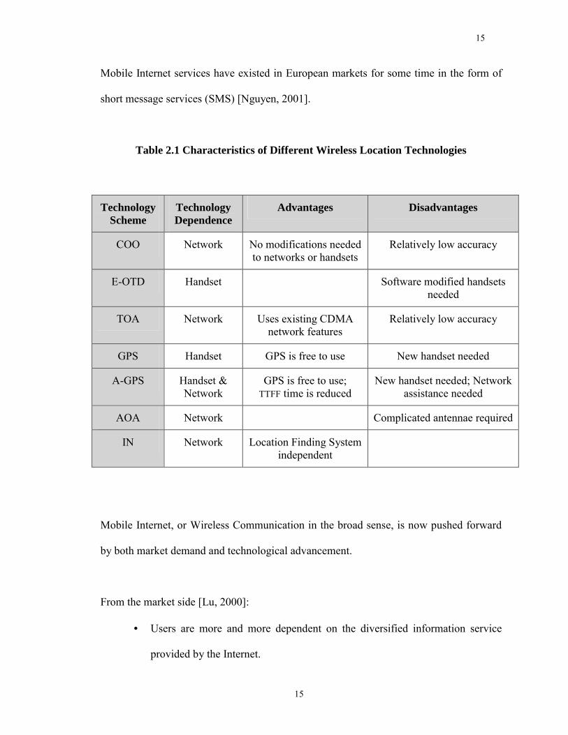
Intelligent Network (IN) solutions. These different types of technologies are summarized
and compared in Table 2.1 [Nguyen, 2001].
The world of Mobile Internet is not simply an advanced stage of Internet evolution, but
rather an entirely new world shaped by mobility. Fixed Internet and mobile telephony
have been deemed as two of the most influential technological developments in the past
five years. The convergence of fixed Internet and mobile telephony ultimately results in
the birth of Mobile Internet. European mobile operators today have a unique position in
deployment of the Mobile Internet infrastructure. Unlike in North America where new-
breed companies dominate the world of the fixed Internet, providing either access or
content, in Europe large telephony companies dominate the fixed Internet. In fact, simple
15
15
Mobile Internet services have existed in European markets for some time in the form of
short message services (SMS) [Nguyen, 2001].
Table 2.1 Characteristics of Different Wireless Location Technologies
Technology Scheme
Technology Dependence
Advantages Disadvantages
COO Network No modifications needed to networks or handsets
Relatively low accuracy
E-OTD Handset Software modified handsets needed
TOA Network Uses existing CDMA network features
Relatively low accuracy
GPS Handset GPS is free to use New handset needed
A-GPS Handset & Network
GPS is free to use; TTFF time is reduced
New handset needed; Network assistance needed
AOA Network Complicated antennae required
IN Network Location Finding System independent
Mobile Internet, or Wireless Communication in the broad sense, is now pushed forward
by both market demand and technological advancement.
From the market side [Lu, 2000]:
• Users are more and more dependent on the diversified information service
provided by the Internet.
16
16
• There is an economic development trend driven by "Mobility + Information".
• People are more and more mobile than ever before.
From the technological side:
• Network Technology keeps evolving. Compared to the wireline network, the
current wireless network is still far from being perfect in terms of bandwidth,
delay, error rate and connection stability. However, the growth and
application of 1G and 2G technologies like CDPD and GSM, 3G
technologies, and protocols like WAP, SOAP and GPRS, have laid a good
foundation for wireless Internet applications.
• Terminal equipment tends to be more diversified. Limitations in CPU
computation speed, storage capacity, display size, keyboard size and battery
life are being eased. A lot of new handheld equipment like PDA, Palm, and
smart phone is adequate for Mobile Internet services.
Some of the most powerful and influential companies in the world ─ Microsoft, Sun,
Motorola, 3Com, Hewlett-Packard, Ericsson, Oracle ─ are developing hardware,
software and networking equipment for the new category of smart devices to support
Location Based Services. Innovative smaller companies also are creating new platforms
and applications for Mobile Internet and Location Based Services. Although still a
nascent industry, Locations Based Services are expected to have a major impact on the
market.
17
17
2.2 LBS System Architecture
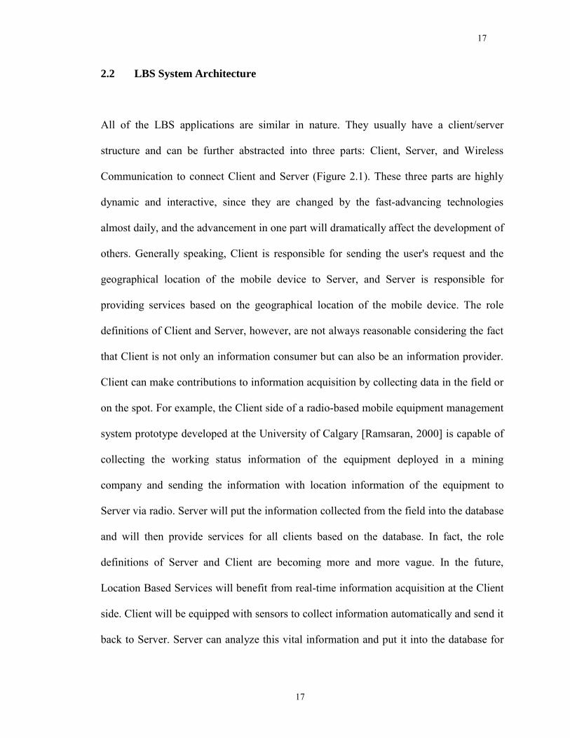
All of the LBS applications are similar in nature. They usually have a client/server
structure and can be further abstracted into three parts: Client, Server, and Wireless
Communication to connect Client and Server (Figure 2.1). These three parts are highly
dynamic and interactive, since they are changed by the fast-advancing technologies
almost daily, and the advancement in one part will dramatically affect the development of
others. Generally speaking, Client is responsible for sending the user's request and the
geographical location of the mobile device to Server, and Server is responsible for
providing services based on the geographical location of the mobile device. The role
definitions of Client and Server, however, are not always reasonable considering the fact
that Client is not only an information consumer but can also be an information provider.
Client can make contributions to information acquisition by collecting data in the field or
on the spot. For example, the Client side of a radio-based mobile equipment management
system prototype developed at the University of Calgary [Ramsaran, 2000] is capable of
collecting the working status information of the equipment deployed in a mining
company and sending the information with location information of the equipment to
Server via radio. Server will put the information collected from the field into the database
and will then provide services for all clients based on the database. In fact, the role
definitions of Server and Client are becoming more and more vague. In the future,
Location Based Services will benefit from real-time information acquisition at the Client
side. Client will be equipped with sensors to collect information automatically and send it
back to Server. Server can analyze this vital information and put it into the database for
18
18
service. The possible applications for information collecting at the Client side include
Equipment Management, Asset Track, Intelligent Distribution, Dynamic Working Plan,
Traffic Control, On-line Survey and so on. Although it is a trend for Location Based
Services to collect information at the Client side, there are still some problems caused by
wireless communication. Information acquisition at Client side is likely to be more
popular in the near future when 3G is fully implemented.
Figure 2.1: Location Based Services Components
Client, Server, and Wireless Communication of Location Based Services can be further
divided into an aggregation of functions. While some functions can be intrinsic and
indispensable for Location Based Services, the other functions might not. Although the
functions of each part are application-dependent, i.e. the functions of a part are fully
determined by the specific applications and the functions for one application might be
different from those for others, the collective functions of a part can still be generalized
and abstracted into a function set, or in other words a function pool. The functions for a
certain application will fall into a subset of the function pool. The architecture of
19
19
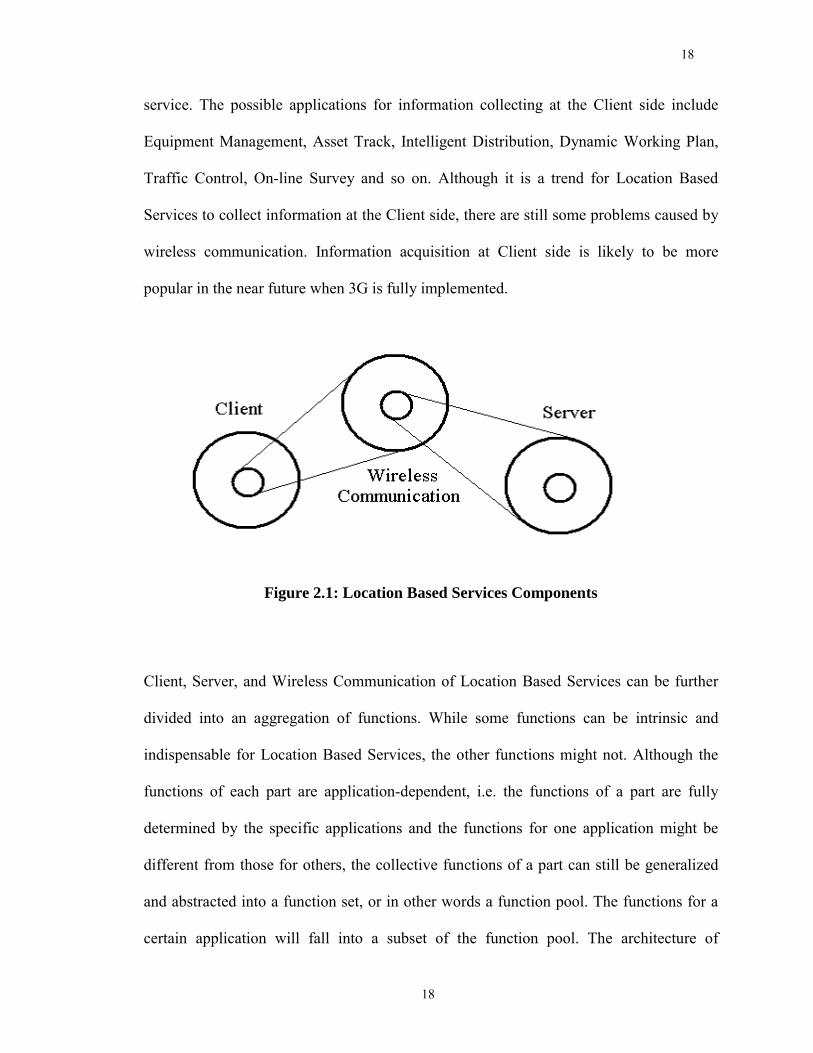
Location Based Services is shown in Figure 2.2, and the functions of each component are
described in the following.
Figure 2.2: Location Based Services Architecture
Client
The function pool of Client is as follows:
• Display Function: A display device, usually a screen, is used to display the
text or multimedia information to users.
• Information Collecting Function: The ability to collect information from
equipment like a GPS receiver or information input manually. In the second
case, the handheld device should provide a user-friendly interface.
• Peripheral Control Function: The ability to control peripheral equipment
connected to the handheld devices. The control information can be generated
by the local handheld device or received from remote control center.
20
20
• Computing Function: The ability to perform tasks such as mathematical
computation, multimedia compression, and information encryption etc.
• Wireless Connection Function: The ability to connect the server with wireless
communication.
• Save Function: The ability to save information for future use.
• Multimedia Function: The ability to display multimedia information like voice
and pictures.
Server
The function pool of Server is as follows:
• Network Function: The ability to transfer over multiple protocols, multiple
operating systems and web browsers on Internet and Intranet.
• Database Function: Server should have the ability to manage and utilize the
database to save the information and provide service for Client.
• Computing Function: The ability to perform tasks such as mathematical
computation, multimedia compression, and information encryption, etc.
• Multimedia Function: The ability to display multimedia information like voice
and pictures.
• Business Logic Function: The ability to provide business logic in a distributed
network for applications.
21
21
• Wireless Connection Function: The ability to support wireless
communication. It is useful when Server is moving and has no fixed Internet
access, or Client has no Internet access and has to communicate with Server
directly.
Wireless Communication
The function pool of Wireless Communication is as follows:
• Receive Function: Wireless Communication should have the ability to transfer
services information from Server to Client.
• Send Function: Wireless Communication should have the ability to transfer
the request and location information from Client to Server. The send function
is not always essential. For example, it is possible for the service provider to
detect the appearance of the mobile device via wireless network, and send the
information to the client even without request.
• Real-time Function: The ability to support real-time Location Based Services.
Not all Location Based Services need real-time communication, and not all
wireless communication technologies support real-time communication.
• Post Function: The ability to post data to the web.
• Read Function: The ability to read data on the web.
22
22
• Compression Function: The ability to compress information before sending
and to restore information after receiving. This function needs cooperation
from Client and Server.
• Encryption Function: The ability to encipher messages before sending and to
decipher messages after receiving. This function needs cooperation from
Client and Server.
• Information Security Function: The ability to ensure that the only authorized
users receive the information.
This function classification is the first step for Client, Server, and Wireless
Communication to pursue reusability. However, the methods and the procedures used to
realize reusability for each of them are different in each case. At the Client side,
hardware compatibility is the core problem for application developers to realize
reusability. There are so many products available now for Client, such as laptops,
handheld PCs, PDAs, pocket PCs, smart phones, GPS receivers, etc. Considering power
consumption, computation ability, size, hardware interface, and screen issues, there is not
a universal solution to meet the requirements of all users. At the Server side, the thorniest
problem lies in network compatibility. The program running on the Server side should
support multiple operating systems, web browsers, and protocols that are proliferating
rapidly on the Internet and Intranet. Compared to those for Client, the available choices
in the market for Wireless Communication are much less, especially in the market for
wide area mobile wireless communication. The most common and dominant method of
wireless communication available today is the commercial cellular telephone system.
23
23
Compared to Server, the protocols for Wireless Communication are much less, although
they are still various. Moreover, different types of wireless communication are highly
complementary and easily merged. As discussed in Chapter 1, Wireless Communication
has many potentials for software reuse. Comprehensively speaking, it is easier to build a
framework for Wireless Communication to support Location Based Services than it is to
build a framework for either Client or Server, this is the most important reason for us to
choose Wireless Communication as our first step toward the aim of software reuse for
LBS.
24
24
Chapter 3
Wireless Communication
Wireless communication is one of the most critical parts in the development of LBS
applications. In this chapter, different wireless communication technologies are
introduced and four of them are chosen and recommended as the best candidates to
improve software reusability for different LBS applications. To enable the LBS
application developers to take advantage of the wireless technologies and services, it is
possible to find some of the most popular wireless technologies available on the market
for software reuse. In combination, those wireless technologies that are chosen, not all the
wireless technologies available on the market since there are too many, should meet the
demands of different LBS applications as fully as possible. Programs can be developed
into reusable components and be fully tested to get high reliability and best performance.
Then, through a standard form known by both the component developers and the LBS
application developers, such as Object-Oriented technology, the LBS application
developers can use the components to develop applications, instead of developing their
own wireless communication software from scratch. Using components can improve the
reusability and quality of the software while avoiding conflicting implementations for
different applications. As a result, the reusability of the software will reduce development
costs and improve the stability of the LBS application systems to be developed.
25
25
3.1 Introduction to Current Wireless Technologies
Wireless Communication technology is usually divided into two main categories:
Terrestrial Wireless Communication, also called Ground-based Wireless Communication,
and Satellite Wireless Communication, also called Sky-based Wireless Communication.
Both Terrestrial Wireless Communication and Satellite Wireless Communication are
comprised of many wireless technologies. The technical aspects of each technology are
not included here since they are beyond the scope of this survey. For further information,
please consult the references listed at the end of this document.
3.1.1 Terrestrial Wireless Communication
I) Pre-3G Technologies
AMPS/CDPD
Advance Mobile Phone Service (AMPS) is a first-generation cellular telephone system
standard that was developed in the late 1970s. This analog-based system uses frequency
bands around 900 MHz with channel bandwidth of 30 kHz. Cellular Digital Packet Data
(CDPD) is a packet-switched data service that uses the existing AMPS network to
transmit data at a rate of 19.2 kbps. CDPD is a connectionless, multi-protocol network
service that provides a peer network extension to an existing data communications
26
26
network. It is designed to operate as a transparent overlay on the AMPS system [Ha,
2001; Lin, 2001; Wong, et al., 1995].
GSM
Global System for Mobile (GSM) is a second-generation cellular telephone system
standard that was developed to replace and unify the disparate first-generation European
cellular systems. It is now the world's most popular standard for new cellular radio and
personal communication equipment. The primary data service that GSM that offers
today is circuit-switched, providing data rates of 9.6 kbps. The new higher-speed
alternative is High-Speed Circuit-Switched Data (HSCSD), which offers download
speeds up to 56 kbps and upload speeds up to 14 kbps. This service will soon be
available from operators such as Orange in the United Kingdom, SingTel in Singapore
and Sonera Corp. in Finland, but most operators are not pursuing HSCSD and instead are
placing their bets on a 2.5G technology called General Packet Radio Service (GPRS)
[Ha, 2001; Lin, 2001; Wong, et al., 1995; Regis, 2000].
Dedicated Mobile Data Network
Unlike AMPS and GSM that can be used for both voice and data, the Dedicated Mobile
Data Network is dedicated to providing data-only services. Among the current Dedicated
Mobile Data Networks, the Mobitex system is the most popular one. Mobitex is a
wireless network architecture that specifies a framework to support all the wireless
27
27
terminals in a packet-switched, radio-based communication system. The three major
components of a Mobitex network are the radio base station, the MX switch, and the
network management center (NMC). Mobitex was developed in 1984 by Eritel, an
Ericsson subsidiary, for the Swedish Telecommunication Administration [Wong et al.,
1995; Virginia Tech., 2000; Mobile Info Website, 2001].
CDMA
Code Division Multiple Access (CDMA) is a second-generation cellular telephone
system that was first deployed around 1995. Today, CDMA networks based on the IS-
95A standard offer circuit-switched data service up to 14.4 kbps (with actual throughput
closer to 13 kbps). Operators in Japan and Korea have adopted an enhanced version of
the standard, IS-95B, which increases data rates to about 64 kbps and support packet
mode [Ha, 2001; Regis, 2000].
II) Impending Technologies (3G and beyond)
Since the launch of the third-generation project by the International Telecommunication
Union (ITU), a total of 15 proposals from around the world had been submitted as of as
of June 1998. Of the 10 radio transmission technologies (RTT) candidates put forth for
terrestrial mobile systems, eight were based on direct-sequence CDMA (DS-CDMA)
digital technology but with a number of different choices in key parameters and technical
details. Therefore, harmonization is essential in order to either maximize the
28
28
commonality between specifications of different RTT proposals or achieve a single
converged global 3G standard. As of today, the harmonization process yields two
distinct and irreconcilable 3G standards � WCDMA and cdma2000 [Ha, 2001].
WCDMA
The 3G solution for GSM is called WCDMA (Wideband CDMA) and is also known as
UMTS (Universal Mobile Telephone System). WCDMA will require a new radio
spectrum as it operates in ultra wide 5-MHz radio channels, which is completely different
from GSM's current 200 kHz channels. However, the data network for WCDMA will
likely be based on EDGE/GPRS infrastructure protocols. WCDMA meets the IMT-2000
requirements of 384 kbps outdoors and 2 Mbps indoors. The earliest initial deployment
will be by NTT DoCoMo in Japan in 2002, with other operators beginning in 2003 and
later [Ha, 2001; Lin, 2001].
cdma2000
Beyond IS-95B, CDMA evolves into 3G technology as a standard called cdma2000.
cdma2000 comes in two phases. The first, with a specification already completed, is
1XRTT, while the next phase is 3XRTT. The 1X and 3X refer to the number of 1.25
MHz wide radio carrier channels used. cdma2000 includes numerous improvements over
IS-95A, including more sophisticated power control, new modulation on the reverse
channels, and improved data encoding methods. The result is significantly higher
29
29
capacity for the same amount of spectrum, and indoor data rates up to 2Mbps that meet
the IMT-2000 requirements. The full-blown 3XRTT implementation of CDMA requires
a 5MHz spectrum commitment for both forward and reverse links. However, 1XRTT
can be used in existing CDMA channels since it uses the same 1.25 MHz bandwidth [Ha,
2001].
3.1.2 Satellite Wireless Communication
Recent technological advancements allow the deployment of satellite networks that
provide voice and data transfer capabilities to every isolated corner of the globe. Three
types of satellite networks exist or are under development: Geostationary Earth Orbit
(GEO), Low Earth Orbit (LEO), and Medium Earth Orbit (MEO) satellite networks.
GEO Satellite Networks
Geostationary satellites are deployed at an orbit of 36,000 km, and rotate at the same rate
and in the same direction as the earth, thus appearing stationary from the ground.
Because the satellite appears at the same position above the horizon all the time, the
antenna's position does not need to be changed. It is a great advantage for those
stationary systems that require a high-gain directional antenna to detect the extremely
weak signal from the far satellites, since there is no requirement for them to adjust the
direction of their antennae.
30
30
One problem with Geostationary satellites is the extreme path loss at the orbital distance
needed, which is typically 36,000 km. When the path loss is large enough that a high-
gain directional antenna will be required, and this is problematic for portable/mobile
operation. This large distance also causes a propagation delay of about 0.25 sec for a
round trip to a Geostationary satellite. This adds unnecessary annoyance to real-time
conversations and delays in data transmission whenever a protocol requires prompt
acknowledgement from the receiving station before the transmission can continue.
Despite their disadvantages, the relative simplicity of Geostationary systems has made
them attractive for the first generation of mobile systems. Global coverage can be
achieved with only three GEO satellites, and all of North and South America can be
covered with one. Immarsat established in 1979 [Ha, 2001; Inmarsat Webpage, 2001],
and MSAT in 1996 are pioneers in mobile wireless communication and they are still very
much in service today [Ha, 2001; TMI Homepage, 2001].
Low Earth Orbit Satellite Networks
Satellite networks with lower orbits (300 ~ 1500 km) can solve some of the problems
associated with Geostationary satellites. However, there are also problems specific to
such satellites. First, their position in space is not fixed with respect to a ground station.
This problem is less important than it might seem. Shorter range results in much less
propagation loss and removes the requirement for highly directional antennas. Secondly,
there is the annoying tendency of such satellites to disappear below the horizon. When
31
31
real-time communication is required, the only way to remedy this problem is to use a
constellation containing more than one satellite. This can make the system quite complex
and expensive. Third, it introduces the Doppler effect, which causes transmission
frequencies to change. To correct this, careful receiver designs for both satellite and
ground stations are required, so that the receiver can lock onto an incoming signal and
track its frequency changes.
LEO satellite systems are very attractive, especially for use with handheld portable
phones. The short propagation distance allows transmitter power and antenna gain
requirements to be less stringent. This permits the use of portable phones that are only
somewhat larger than a conventional cellular phone. However, LEO systems are the
most complex and expensive wireless communication systems yet devised. Good
examples of LEO satellite networks are Iridium, Globalstar, and Teledesic [Ha, 2001].
Medium Earth Orbit Satellite Networks
Satellites in medium earth orbit are a compromise between the LEO and GEO systems.
More satellites are needed than for GEO, but fewer than for LEO. The delay and
propagation loss are much less than for GEO, but greater than LEO. Portable phones are
possible with MEO systems, but they are likely to be heavier and bulkier than those for
LEO systems. At this moment no MEO systems are up and running, but some systems
under development appear likely to become operational in the near future.
32
32
Ellipso
With the world�s population and landmass both weighted heavily in the Northern
Hemisphere, Ellipso uses an interesting combination of elliptical and circular orbits to
match this distribution irregularity. A total of 17 MEO satellites will be deployed; 7 in a
circular orbit of 8,050 km around the equator and 10 in inclined elliptical orbits with
apogees of 7,605 kilometers and perigees of 633 kilometers. Ellipso uses CDMA at
uplink frequencies of 1610.0 - 1621.5 MHz and downlink frequencies of 2483.5 - 2500.0
MHz. Data rates support 28.8kbps and even higher speeds in asymmetric patterns.
Ellipso is also using a next generation air interface based on 3G (third generation)
wireless technology to reduce costs of terminals and to make it easier to offer the most
advanced wireless services available [Ellipso Homepage, 2001].
ICO
The ICO constellation of 10 MEO satellites will be arranged in two planes of 5 satellites
each, at approximately 10,390 km above the earth's surface. The configuration has been
designed to provide coverage of the entire surface of earth at all times. The transmission
frequencies are within the bands of 1985 � 2015 MHz for uplink and 2170 � 2200 MHz
for downlink. The ICO system can support medium data rates up to 144 kbps and will
begin offering its services worldwide in 2003 [ICO Homepage, 2001].
33
33
3.2 Wireless Communication Methods for LBS Applications
After carefully reviewing the currently available Terrestrial Wireless Communication
Systems, CDPD, GSM, Radio Modem in UHF commercial band, Dedicated Mobile Data
Network have been chosen as the best candidates for Location Based Services. The
Wireless Communication candidates to improve software reusability for Location Base
Services applications have been selected based on their popularity, compatibility, and
complementary ability. Popularity is determined by both the network factors and the
handset factors. Important network factors include service charges, data rates, coverages,
protocols supports, and roaming supports which determine the underlying functions of
Location Based Services. Important handset factors include size, weight, and battery life.
All these factors affect the application of Location Based Services. Compared to
Terrestrial Wireless Communication, Satellite Wireless Communication usually has a
better coverage, but needs more bulky and battery-consuming user equipment to
exchange signals with satellites. The successful Wireless Communication technology for
Location Based Services should be a mature technology to ensure the quality of
communication. Generally speaking, Satellite Wireless Communication is relatively
immature when compared to Terrestrial Wireless Communication. The services based on
Satellite Wireless Communication are more unreliable and expensive than those based on
Terrestrial Wireless Communication. Currently Satellite Wireless Communication is still
away from the mainstream for Location Based Services. Compatibility determines if
these different wireless technologies can support the same user interface, which forms the
basis of software reuse. The complementary ability helps the combination of these
34
34
wireless technologies to meet the requirements of different LBS applications as fully as
possible. As a result, more market place can be covered by the combination of these
wireless technologies that are chosen.
3.2.1 CDPD
CDPD is one of the most important mobile data networks in North American. In Canada,
CDPD service is now available in seven provinces. The CDPD is emerging into a
national wide network in both USA and CANADA [Ha, 2001; Lin, 2001; Wong et al.,
1995].
The service charge is relatively low with a flat monthly rate about a few tens of dollars in
Canada. Further, the CDPD service charge is based on the volume of data and there are
no roaming or long distance charges.
CDPD can be overlaid on AMPS and IS-136 systems and share its infrastructure
equipment without interference. It is easier for CDPD to merge into a global network
based on the existing global AMPS infrastructure. Although it can be assigned to a
dedicated RF channel, CDPD's distinctiveness is that it transmits packet data over idle
cellular voice channels, and automatically switches to another channel when the current
channel is about to be assigned for voice usage, thus greatly improving its efficiency and
reducing the costs for data transferring [Lin, 2001].
35
35
CDPD can serve as a wireless extension to the Internet or other data networks such as
Public Switched Data Network (PSDN). CDPD supports connectionless network services
where every packet is routed individually based on the destination address of the packet
and the knowledge of the current network topology. CDPD can support both the standard
OSI connectionless network and the Internet Protocol that means that CDPD can support
the popular protocols on the Internet such as TCP/IP and UDP/IP [Wong, 1995].
A CDPD modem has the potential to locate itself by identifying the address of the current
serving MD-IS (Mobile Data Intermediate System) from the channel stream. When the
CDPD modem moves from one serving area to another, it registers itself for the
upcoming serving MD-IS via the registration service. The home MD-IS that is currently
serving the CDPD modem will delete its link with the previous serving MD-IS and build
a new link with the upcoming serving MD-IS. The upcoming serving MD-IS will take
place of the current serving MD-IS to serve the CDPD modem. So at any time, the CDPD
modem will be served by only one MD-IS, the one closest to the CDPD modem. Because
the location of each MD-IS is known, so the location of CDPD modem can be confined
to a small area around the known MD-IS [Lin, 2001]. Although the positioning accuracy
is not as high as GPS, it is still a useful feature toward Location Based Services. The
location registration procedure is illustrated in Figure 3.1.
36
36
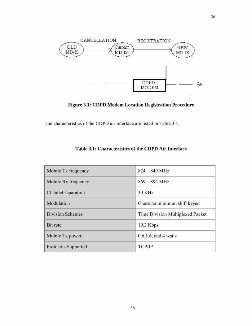
Figure 3.1: CDPD Modem Location Registration Procedure
The characteristics of the CDPD air interface are listed in Table 3.1.
Table 3.1: Characteristics of the CDPD Air Interface
Mobile Tx frequency 824 � 849 MHz
Mobile Rx frequency 869 � 894 MHz
Channel separation 30 KHz
Modulation Gaussian minimum shift keyed
Division Schemes Time Division Multiplexed Packet
Bit rate 19.2 Kbps
Mobile Tx power 0.6,1.6, and 4 watts
Protocols Supported TCP/IP
37
37
3.2.2 GSM
GSM is now the world's most popular standard for new cellular radio and personal
communications equipment. Announced by North American GSM Alliance in 2002
[GSM World, 2002], GSM became the world's leading and fastest growing mobile
standard, spanning over 174 countries, serving more than one in ten of the world's
population.
The service charge of GSM is based on the air time rather than the volume of data. This
charge scheme makes GSM less economical for short messages than CDPD. Short
Message Services (SMS), a standard being incorporated into GSM, is an ideal solution to
send short messages. According to GSM World [GSM World Website, 2001], the SMS
market in the European Union reached one billion short messages per month in April
1999. The market size thereby doubled in about six months. However, compared to
CDPD, SMS is not a good choice for applications that need highly real-time
communication.
The primary data service GSM offers today is circuit-switched that provides a data rate of
9.6 kbps. General Packet Radio Service (GPRS), reuses the existing GSM infrastructure
to provide higher data rate, easier access, and a more attractive service charge using
packet technology [Lin, 2001]. The relationship of GPRS and GSM is quite similar to
that of CDPD and AMPS. With GPRS, GSM resources can be shared dynamically
between speech and data services as a function of traffic load and operator preference.
38
38
Multiple time slots can be allocated to a user, or several active users can share a single
time slot, where the uplink and the downlink are allocated separately. Various radio
channel coding schemes are specified to allow bit rates from 9.6 kbps to more than 150
kbps per user.
The Mobile Station (MS) of GSM consists of two parts: the Subscriber Identity Module
(SIM) and the Mobile Equipment. Similar to CDPD, MS also has the potential of locating
itself by identifying the address of the Home Location Register (HLR) from the channel
stream. When the MS moves from one serving area to another, it registers itself for the
upcoming Visiting Location Register (VLR) via the registration service. The HLR that is
currently serving the MS will delete its link with the previously serving VLR and build a
new link with the upcoming serving VLR. The upcoming serving VLR will take place of
the currently serving HLR to serve the MS and become new HLR while the former HLR
becomes VLR with a link to new HLR. So at any time, the CDPD modem will be served
by only one HLR, the Location Register closest to the MS. Because the location of each
Location Register is known, the location of MS can be confined to a small area around
the HLR [Lin, 2001]. Although the positioning accuracy is not as high as GPS, it is still a
useful feature toward Location Based Services. Different from CDPD, the upcoming
VLR needs information from the previous VLR to find the HLR. The location
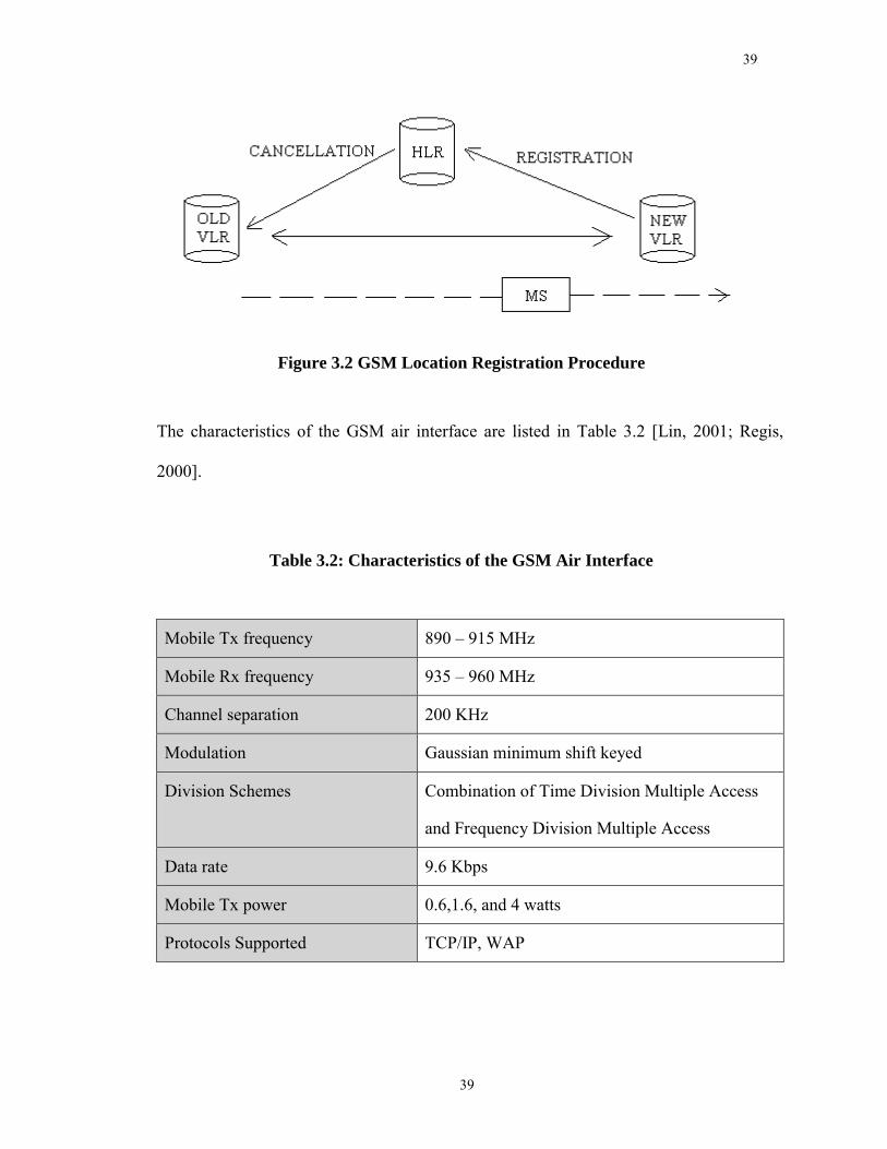
registration procedure is illustrated in Figure 3.2.
39
39
Figure 3.2 GSM Location Registration Procedure
The characteristics of the GSM air interface are listed in Table 3.2 [Lin, 2001; Regis,
2000].
Table 3.2: Characteristics of the GSM Air Interface
Mobile Tx frequency 890 � 915 MHz
Mobile Rx frequency 935 � 960 MHz
Channel separation 200 KHz
Modulation Gaussian minimum shift keyed
Division Schemes Combination of Time Division Multiple Access
and Frequency Division Multiple Access
Data rate 9.6 Kbps
Mobile Tx power 0.6,1.6, and 4 watts
Protocols Supported TCP/IP, WAP
40
40
3.2.3 Radio Modem in UHF Commercial Band
There is a commercial band whose frequency ranges from 450MHz to 470MHz within
UHF band [Pacific Crest, 2000]. Many radio manufactures produce radio at this band to
provide wireless data communication for mobile users. However, the radio waves in UHF
commercial band are crowded and noisy. Since the band is designed for public use and no
one can assume exclusive frequency coordination, cross-channel interferences become
inevitable. The channel separation in UHF commercial band is only 12.5 KHz that is
much smaller than in CDPD and GSM. This smaller channel separation results larger
cross-channel interferences. The interferences seriously deteriorate the communication
quality, and lead to an even smaller radio effective range than Line of Sight (LOS). In an
urban area, where the radio wave environment is bad, radio effective ranges are usually
limited to a few kilometers [Pacific Crest, 1998].
Despite the weakness of communication quality and effective range, the radio modem in
UHF commercial band is still an attractive candidate for Location Based Services. There
are some advantages for using radio frequencies in UHF commercial band: there is no
service charge and the deployment of radio systems is simple and flexible. Moreover,
most of the radios working in the UHF commercial band support packet mode. Packet
mode operation allows packet switching where data is sent to a specific modem in a
network of modems. Packet mode can help radio modems increase communication
quality in a bad radio wave environment. Using packet mode, the radio modem can
support both broadcast and point-to-point communication to increase security. Unlike
41
41
CDPD and GSM, radio modem does not have direct access to the Internet. Although the
mobile user can access the Internet via radio modem with the help of a server, the process
is more difficult and complicated compared to CDPD and GSM. For example, to retrieve
information from the Internet, the mobile user has to send a request via radio modem to
the server, and then the server responds to the user request, retrieves the information from
the Internet, and finally sends the service back to the user via radio modem. Radio
modem is an alternative for Location Based Services in the case where the service does
not require access to the Internet or where access to the Internet is not available.
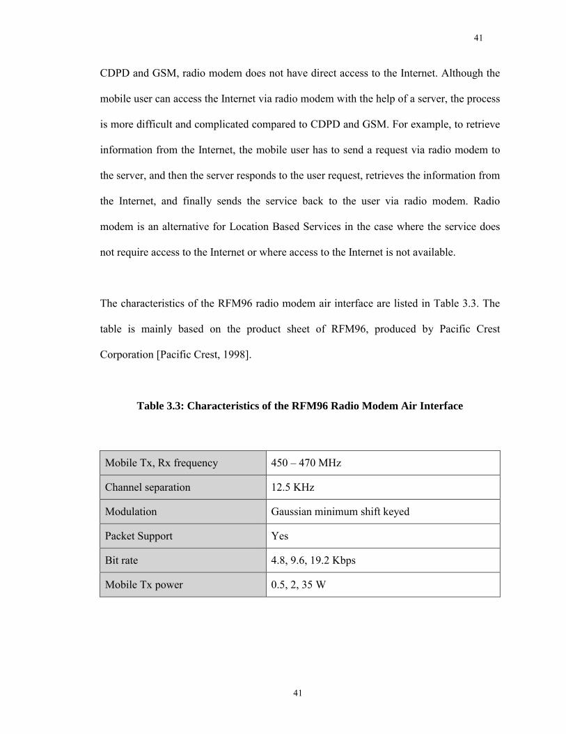
The characteristics of the RFM96 radio modem air interface are listed in Table 3.3. The
table is mainly based on the product sheet of RFM96, produced by Pacific Crest
Corporation [Pacific Crest, 1998].
Table 3.3: Characteristics of the RFM96 Radio Modem Air Interface
Mobile Tx, Rx frequency 450 � 470 MHz
Channel separation 12.5 KHz
Modulation Gaussian minimum shift keyed
Packet Support Yes
Bit rate 4.8, 9.6, 19.2 Kbps
Mobile Tx power 0.5, 2, 35 W
42
42
3.2.4 Dedicated Mobile Data Network
While AMPS and GSM can carry both voice and data, Dedicated Mobile Data Network
is dedicated to providing data-only services. Examples of Mobile Data Networks are
Paknet, Mobitex, Cognito, RD-LAP and its predecessor ARDIS [Wong, 1995]. In terms
of international acceptance, the Mobitex system is far ahead of its rivals. It does have the
advantage of being one of the first, as it evolved from an indirectly modulated system at
1,200 bps in the early 1980's and was adopted by Swedish Telecom. Mobitex networks
are operating in more than 20 countries and several more are planned. In the US, Mobitex
has covered 95% of the population [Virginia Tech., 2000], becoming one of the most
important mobile data networks in North America.
The success of Mobitex lies in the overall performance of the network, which includes all
services and facilities as well as a high level of transparency, which allows the use of
custom applications. The removal of any intellectual property right (IPR) claims and the
placing of the protocol in the public domain significantly helped in the early acceptance
of the system. The data rate of Mobitex is currently 8kbps, not as high as CDPD and
GSM. However, both its redundant architecture design and rugged modulation scheme
ensure that data transmission at Mobitex is highly reliable [Wong, 1995].
Similar to CDPD and GSM, Mobitex also has the potential of locating itself. The
architecture of the Mobitex system is shown in Figure 3.3.
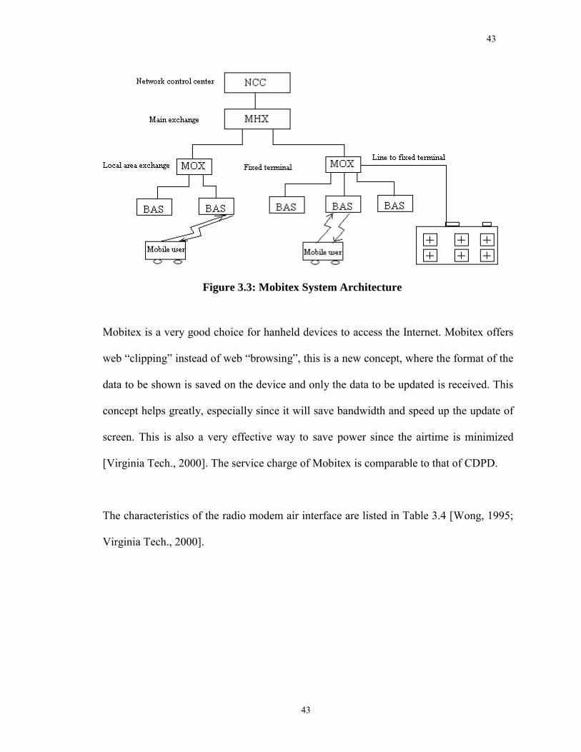
43
43
Figure 3.3: Mobitex System Architecture
Mobitex is a very good choice for hanheld devices to access the Internet. Mobitex offers
web �clipping� instead of web �browsing�, this is a new concept, where the format of the
data to be shown is saved on the device and only the data to be updated is received. This
concept helps greatly, especially since it will save bandwidth and speed up the update of
screen. This is also a very effective way to save power since the airtime is minimized
[Virginia Tech., 2000]. The service charge of Mobitex is comparable to that of CDPD.
The characteristics of the radio modem air interface are listed in Table 3.4 [Wong, 1995;
Virginia Tech., 2000].
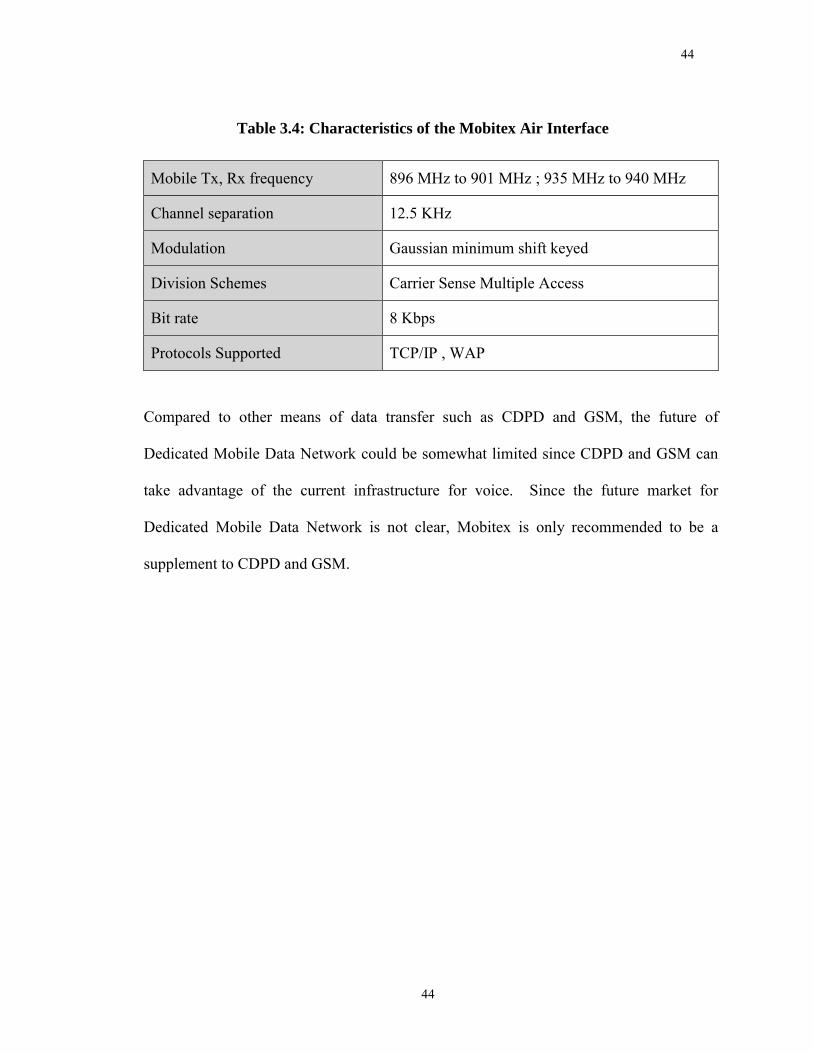
44
44
Table 3.4: Characteristics of the Mobitex Air Interface
Mobile Tx, Rx frequency 896 MHz to 901 MHz ; 935 MHz to 940 MHz
Channel separation 12.5 KHz
Modulation Gaussian minimum shift keyed
Division Schemes Carrier Sense Multiple Access
Bit rate 8 Kbps
Protocols Supported TCP/IP , WAP
Compared to other means of data transfer such as CDPD and GSM, the future of
Dedicated Mobile Data Network could be somewhat limited since CDPD and GSM can
take advantage of the current infrastructure for voice. Since the future market for
Dedicated Mobile Data Network is not clear, Mobitex is only recommended to be a
supplement to CDPD and GSM.
45
45
Chapter 4
Object-Oriented Application Framework
Object-Oriented (OO) Application Framework is one of the most dynamic technologies
in the software domain for improving the software reusability with Object-Oriented
technology. It is believed that Object-Oriented Application Framework will be at the core
of leading-edge software technology in the twenty-first century [Fayad, 1999]. This
chapter provides an overview of the application framework, its strength and weakness,
and an explanation of why and how it promotes software reuse.
Computing power and network bandwidth have increased dramatically over the past
decade. However, the design and implementation of complex software remains expensive
and error-prone. Much of the cost and effort stems from the continuous re-discovery and
re-invention of core concepts and components across the software industry. In particular,
the growing heterogeneity of hardware architectures and the diversity of operating
systems and communication platforms make it hard to build correct, portable, efficient,
and inexpensive applications from scratch [Fayad et al, 1997]. Among various solutions
for reducing software costs, increasing software reusability is the best one [Ellis, 1994].
Emerging in 1960's and getting fledged in 1980's, Object-orientation is a promising
technology for improving the reusability of software designs and implementations in
order to reduce the cost and improve the quality of software. Unlike other OO
technologies, Object-Oriented Application Framework is targeted to achieve maximum
software reusability for particular business units (such as data processing or cellular
46
46
communications) and application domains (such as user interfaces or real-time avionics)
[Fayad, 1999].
4.1 Concept of OO Application Framework
Object-Oriented Application Framework, or framework for short, is a very important
concept for the software industry as well as academia at this time when software systems
are becoming increasingly complex.
Object-Oriented Application Framework is a promising technology for applying proven
software designs and implementations in order to reduce the costs and improve the
quality of software [Fayad, 1999]. As one of the most dynamic technologies in the
software domain, the definition of framework varies. A frequently used definition is "a
framework is a reusable design of all or part of a system that is represented by a set of
abstract classes and the way their instances interact". Another common definition is "a
framework is the skeleton of an application that can be customized by an application
developer." These are not conflicting definitions; the first describes the structure of a
framework while the second describes its purpose [Johnson, 1997]. Nevertheless, they
point out the difficulty of defining frameworks clearly. In contrast to earlier OO reuse
techniques based on class libraries, frameworks are targeted for particular business units
(such as data processing or cellular communications) and application domains (such as
user interfaces or real-time avionics). Frameworks like Microsoft Foundation Classes
(MFCs), Microsoft's Distributed Common Object Model (DCOM), JavaSoft's Remote
47
47
Method Invocation (RMI), and implementations of the Object Management Group's
(OMG) Common Object Request Broker Architecture (CORBA) play an increasingly
important role in contemporary software development [Fayad, 1999].
The most important part of a framework is the way in which the system that it represents
is divided into components [Deutsch 1989]. Frameworks also reuse implementation, but
that is not so important as the reuse of the internal interfaces of a system and the way the
functions are divided among its components. This high-level design is the main
intellectual content of software, and frameworks are a way to reuse it [Fayad, 1999].
Frameworks are realized by Object-Oriented technology and take advantage of all three
of the distinguishing characteristics of Object-Oriented programming languages: data
abstraction, polymorphism, and inheritance. Like an abstract data type, an abstract class
represents an interface behind which implementations can change. Polymorphism is the
ability of a single variable or procedure parameter to take on values of several types.
Object-Oriented polymorphism lets a developer mix and match components, lets an
object change its collaborators at run-time, and makes it possible to build generic objects
that can work with a wide range of components. Inheritance makes it easy to make a new
component [Fayad, 1999].
A framework is essentially an application but one for a special purpose. According to
Johnson and Foote, a framework is a reusable, semi-complete application that can be
specialized to produce custom applications [Johnson-Foote 1988]. Sometimes framework
48
48
is an entire application; sometimes it is just a subsystem. The framework describes not
only the component objects but also how these objects interact by describing the interface
of each object and the flow of control between them. In other words, it describes how the
responsibilities of the system are mapped onto its objects [Johnson and Foote 1988;
Wirfs-Brock 1990].
49
49
4.2 Strengths and Weaknesses of OO Application Frameworks
Object-Oriented Application Framework can significantly increase software quality and
reduce development effort when used in conjunction with patterns, class libraries, and
components. The primary strengths of Object-Oriented Application Frameworks stem
from the modularity, reusability, extensibility, openness and inversion of control they
provide to developers. However, a number of challenges must be addressed in order to
employ frameworks effectively. Challenges such as development effort, learning curve,
integrality, maintainability, validation and defect removal, efficiency, and lack of
standards, have to be recognized and resolved fully. The main strengths and weakness are
described as follows [Fayad, 1999]:
Modularity: Frameworks enhance modularity by encapsulating volatile implementation
details behind stable interfaces. Framework modularity helps improve software quality by
localizing the impact of design and implementation changes. This localization reduces the
effort required to understand and maintain existing software.
Reusability: The stable interfaces provided by frameworks enhance reusability by
defining generic components that can be reapplied to create new applications. Framework
reusability leverages the domain knowledge and prior effort of experienced developers in
order to avoid recreating and revalidating common solutions to recurring application
requirements and software design challenges. Reuse of framework components can yield
substantial improvements in programmer productivity, as well as enhance the quality,
50
50
performance, reliability, and interoperability of software. Reuse of framework
components also decreases the time to market, which is extremely important in business.
A good framework can reduce by an order of magnitude the amount of effort needed to
develop customized applications [Fayad, 1999].
Extensibility: A framework enhances extensibility by providing explicit hook methods
that allow applications to extend its stable interfaces. Hook methods systematically
decouple the stable interfaces and behaviors of an application domain from the variations
required by instances of an application in a particular context. Framework extensibility is
essential to ensure timely customization of new application services and features [Pree
1995].
Open structure: Since the early 1980s, Object-Oriented Application Frameworks have
demonstrated that OO programmers can encapsulate reusable software architecture as a
collection of collaborating, extensible object classes. Such frameworks are particularly
important for developing open systems in which not only functionality but also
architecture is reused across a family of related applications [Demeyer and et al., 1997].
An open structure enables the users to easily mix and match components from different
vendors.
Inversion of control: The runtime architecture of a framework is characterized by an
inversion of control. This architecture enables canonical application processing to be
customized by event handler objects that are invoked via the framework's reactive
51
51
dispatching mechanism. When events occur, the framework's dispatcher reacts by
invoking hook methods on pre-registered handler objects, which perform application-
specific processing on the events. Inversion of control allows the framework rather than
each application to determine which set of application-specific methods to invoke in
response to external events (such as window messages arriving from end users or packets
arriving on communication ports) [Fayad, 1999].
Additional Protection: A framework can provide protection to avoid possible disaster in
applications due to the mistakes made by either application developers or users. For
example, an application developer may select a protocol by mistake, which is not
supported by the equipment of the system. The framework can help to solve this type of
problems by either providing the user an error report, or simply disabling that protocol so
the user cannot select it.
Development effort: While developing complex applications is hard enough, developing
high-quality, extensible, and reusable frameworks for complex application domains is
even harder. The software process and design principles associated with developing
Object-Oriented Application Frameworks are generally more complicated than those with
common applications. Development effort is a main weakness of Object-Oriented
Application Frameworks.
Learning curve: Learning to use an Object-Oriented Application Framework effectively
requires considerable investment of effort. For instance, it often takes 6 to 12 months to
52
52
become highly productive with a GUI framework like MFCs or MacApp, depending on
the experience of the developers. A relatively smaller and simpler Object-Oriented
Application Framework that targets a specific area may not take such a long time.
However, the training time is still significant compared to that of common applications.
Typically, hands-on mentoring and training courses are required to teach application
developers how to use the framework effectively.
Efficiency: Frameworks enhance extensibility by employing additional levels of
indirection. For instance, dynamic binding is commonly used to allow developers to
subclass and customize existing interfaces. However, the resulting generality and
flexibility often reduce efficiency. For instance, the use of dynamic binding needs more
system resources and slows the program's running speed. It is natural that people are
skeptical about using Object-Oriented Application Frameworks to support time-critical
applications. In fact, the efficiency of Object-Oriented Application Frameworks is not so
bad as it might seem. With the advance of computing devices and algorithms, Object-
Oriented Application Frameworks can support even the most time-critical applications.
For some extremely time-critical applications, Object-Oriented Application Frameworks
may provide support by trading flexibility and power for efficiency and simplicity.
53
53
4.3 OO Technology and Software Reusability
4.3.1 Software Reusability
Software reusability was not urgent for early computer programmers. In 1955, software
cost was merely about 20% of the system cost [Ellis, 1994]. Software was much more
treated as an attachment of hardware rather than as an equal partner. Early software was
much simpler and less expensive than the contemporary, and it was affordable to develop
specific programs for different applications. In a word, there was not enough demand to
motivate the development of software reusability. With the rapid development of
software applications, in the 1960's, people found the requirements for software to be
more than all available engineers could possibly develop [Ellis, 1994]. The relation
between software requirement and supply became worse and worse in the 1970's and
1980's. A new word came up to describe this phenomenon: "Software Crisis". Up to now,
the best method of dealing with the Software Crisis is to increase the software reusability
[Ellis, 1994].
Software reusability is about creating components that can be used in all relevant
contexts with the minimum of effort [Biddle et al, 1995]. The key terms here are
"relevant contexts" and "minimum of effort". A complete description of the effort
required to use the component must include the effort required to determine what
components are available, the effort required to confirm that a component is relevant to
the intended use, and the effort required to use that component properly. Although the
54
54
first two steps are important, it is the last that has the biggest impact on the reusability of
software ─ a component that requires a user to make it useful is not a very useful one
[Biddle et al, 1995].
Three important properties of code that make it more reusable are generality, flexibility,
and safety [Andreae, 1994]. Generality is about structuring the component so that its
behavior details can be customized. Flexibility is about minimizing the requirements of
the context on what components are appropriate. Safety is making sure that the features
for generality and flexibility do not result in the wrong components being used [Biddle et
al, 1995].
Although the term "Software Reusability" immediately conjures up the image of code
reuse, it is not limited to code reuse alone. To maximize the benefits of software
reusability, the development process must structure the design documentation and test
documentation and results to allow their direct reuse as well. These are far more costly
than the code itself [Ellis, 1994].
4.3.2 Object-Orientation Methodology
Since the late 1980s, there has been a great deal of excitement and interest in Object
Orientation in the information technology industry and in academia. While the concept of
object-orientation emerged as early as late 1960s when the SIMULA language was
55
55
invented in Norway, the systematic approach was formalized and developed in 1980s
[Graham, 1991].
Object Orientation, also called Object-Oriented methodologies and Object-Oriented
Programming (OOP), is a revolutionary concept that changed the rules in computer
program development. Object Orientation is organized around objects rather than
actions, data rather than logic. Historically, a program has been viewed as a logical
procedure that takes input data, processes it, and produces output data. The programming
challenge was seen as how to write the logic, not how to define the data. Object-oriented
programming takes the view that what we really care about are the objects we want to
manipulate rather than the logic required to manipulate them. Examples of objects range
from human beings (described by name, address, and so forth) to buildings and floors
(whose properties can be described and managed) down to the little widgets on your
computer desktop such as buttons and scroll bars [TechTarget, 2000].
Class may be considered a mold from which objects are extracted. Complete definitions
of Class and Object are as follows [Ellis, 1994]:
Object: a logical programming entity that encapsulates state or value in data fields and
predefined behavior in methods. Each object is an instance of a class, but has unique
identity distinct from all other objects. Fields and methods may either be defined by the
object's class or inherited from an ancestor classes.
56
56
Class: a common structure and behavior shared by a set of objects. Classes have an
interface segment, describing the visible characteristics of member objects, and an
implementation segment, defining the hidden implementation secrets of its behavior.
Three primary characteristics underlie the principles of Object-Orientation. Their
definitions are as follows [Ellis, 1994]:
Encapsulation: the mechanism of modularity by which the fields (data structures) and
methods (procedures and functions that define the object's behavior) of an object are
structured to allow only explicitly defined access to the object's structure and behavior
while hiding implementation details from the object's clients.
Inheritance: a relationship between objects wherein one object automatically acquires
fields and methods from one or more other objects. Hierarchy diagrams show
ancestor/descendent relationships in the same manner as a family tree illustrates
inheritance.
Polymorphism: the property by which objects in a hierarchy can share a single method
name, wherein each object implements the method in a manner dictated by its unique
requirements.
Two key ideas are implemented in Object Orientation to deal with complexity in
programming [Biddle et al, 1995]. The first idea is that programmers should design their
57
57
programs by analogy. That is, programmers should organize their programs using
structures like the structures in the application domain. The second idea is that most
application domains, like the real world, should be structured as entities and actions on
entities. In other words, the world can be seen as a world of things and doing. These two
key ideas can lead directly to high software reusability, easier software design, easier
software understanding, and easier software maintenance. The detail is explained in the
following two sectors: Software Reusability and Object Orientation, Other Benefits of
Object Orientation.
4.3.3 Software Reusability and Object Orientation
The most important merit of Object-Orientation is its positive effect on software
reusability [Ellis, 1994]. The benefits may be minimal for the first few applications. But
in this critical stage, proper use of Object Orientation technology can lead to a library of
reasonable components. Thereafter, programmers can reap direct benefits from the library
in reduced cost and development schedule.
Design by analogy, as mentioned before, leads directly to reusability. In the world of
entities and actions, it is typical that both entities and actions are involved in many
different contexts. The same entities are used for various purposes, and the same action
may be applied to various entities. Accordingly, when we design by analogy, we are
likely to use structures that either have already been needed and designed, or that will be
needed in the future [Biddle et al, 1995].
58
58
Object Orientation supports Software Reusability by its three primary characteristics:
Encapsulation, Inheritance, and Polymorphism.
Encapsulation and Reusability:
One of the key ideas from the technical foundation of Object Orientation was the idea of
encapsulation. This means that the object or class is a capsule, whereby the behavior and
state are bound together as a unit, with the only access being the designated operations.
There are strong reasons for reusability in this approach.
For the object or class to be reusable in different contexts (context is a term that
represents the place where the reusable objects or classes are used), it is necessary to
make certain that the behavior cannot be interfered with. For example, a queue class
cannot permit any particular context code to directly manipulate its implementation,
because it may compromise the integrity of the queue when used in other contexts.
Moreover, the reusability issue here can work both ways. If it might be useful to use the
context code together with a different implementation of the object or class, then the
reusability of the context code is of interest. Accordingly, it is important that the context
code cannot depend upon the implementation of the class or object at all. For example,
context code cannot be permitted even to access a queue implementation, because then it
becomes dependent on that particular implementation, and so limits its reusability.
59
59
Encapsulation therefore supports reusability by ensuring that neither modification nor any
access is permitted from context to object or class implementation. The reverse case is
also important ─ the context must be protected from the object ─ for the same reasons,
and encapsulation can also provide this protection. We regard the role of encapsulation
here as supporting reusability by providing safety: ensuring code will be usable in other
contexts [Biddle et al, 1995].
Inheritance, Polymorphism and Reusability:
One of the ways we deal with the real world is by organizing objects with similar
operations and behavior into classes. Simple classification cannot always adequately
represent the necessary complexities. One such situation occurs when there are objects
that do seem to belong in a class, except for some specialized operations and behavior. In
the real world this leads to taxonomical hierarchies, with a general category at the top of
which is then divided and sub-divided into increasingly specialized cases.
In Object Orientation, this kind of classification hierarchy is usually represented by
Inheritance and Polymorphism. While Inheritance means that objects of the specialized
class conform to the interface of the base class in a primitive way by ignoring any
specialized behavior, Polymorphism implies an extra step, where specialized objects
conform to the base class interface, but retain their specialized behavior. Inheritance and
Polymorphism seem to be the most celebrated mechanisms in Object Orientation
technology, but also the most misunderstood [Biddle et al, 1995].
60
60
The basic idea of Inheritance and Polymorphism is that an object of a more specialized
class inherits the operations and behavior of a more basic class. The usual claim is that
this is a big advantage because it involves reusing the operations and the behavior of the
base class. The real advantages of Inheritance and Polymorphism are gained because the
new class conforms to the interface of the base class. That is: any place an object of the
base class can be used, any object of the specialized class can too. Accordingly, any
context code that takes objects of the base class can also be used with objects of the
specialized class. For example, if a manager is regarded as a specialized form of
employee, any program that uses employees will also work with managers. These are the
real advantages of Inheritance and Polymorphism: They make the context code reusable.
Although Object Orientation has great potential to foster reusability, programmers and
designers need to understand it well enough to turn potential into results. Any assumption
that Object Orientation will automatically result in reusability certainly is not the truth
and will incur skepticism about Object Orientation technology. The relationship between
Object Orientation and software reusability has some important implications for Object-
Oriented Design (OOD). Most importantly, program designers hoping to achieve
reusability must understand how Object Orientation can help deliver it. The process of
Object-Oriented Design is largely one of class identification and class organization. At
any point in the design, it is reasonable to consider whether, and how well, reusability
caters for future reuse. Throughout the design process, understanding how Object
61
61
Orientation can deliver reusability will illuminate attractive options, and help lead to
success [Biddle et al, 1995].
4.3.4 Other Benefits of Object Orientation
Design by analogy can lead to easier program design, easier program understanding, and
can also benefit program maintenance. The design is easier because there is a guiding
philosophy: design the program like the domain itself. So if you understand the domain,
you can proceed with the design. And if, according to the same principles, someone has
written the program: design by analogy, the others who understands the domain have a
head start in understanding the program. The effect of Object Orientation on program
maintenance is more delicate ─ Object Orientation does not necessarily make
maintenance easy. However, because the program is structured like the domain, changes
in the domain will lead to similar changes in the program, and they will be of a similar
complexity. This last aspect can greatly improve relations between programmer and
client [Biddle et al, 1995].
It is believed that there is a very direct connection between Object Orientation and
enhanced interoperability [Berard, 2000]. Interoperability is the ability to exchange
functionality and interpretable data between two software entities [Mowbray, 1994].
Interoperability is very useful when dealing with a complicated system that is composed
of various hardware and/or software such as the Internet. Polymorphism, if properly used,
62
62
can significantly reduce the overall complexity of a system and thus enhance the
interoperability [Berard, 2000].
63
63
4.4 OO Application Framework and Software Reusability
Frameworks are just one of many software reuse technologies [Kreuger 1992]. Reuse
technologies range from the simple and inflexible to the complex and powerful. Code
reuse and design reuse are two bases of software reuse. While the code reuse represents
the concrete part of software reuse, like a component, design reuse represents the abstract
part of software reuse, like a textbook [Fayad, 1999].
In the beginning, commercial interest in object-oriented technology focused on code
reuse. More recently, pure design reuse has become popular [Bushmann 1996; Coplien
1996; Fowler 1997; Gamma 1995; Vlissides 1996]. Frameworks are an intermediate form
of software reuse, part code and part design reuse. Frameworks eliminate the need for a
new design notation by using an object-oriented programming language as the design
notation. Although programming languages suffer several defects as design notations, it
is not necessary to make specialized tools to use frameworks. Most programmers using a
framework have no tools other than their compilers. Object-Oriented Application
Frameworks are different from other software reuse technologies through distinct
implementation of code and design reuse.
4.4.1 Frameworks and Components
Frameworks are basically a type of component, but frameworks are much more
customizable than most components. The more customizable a component is, the more
64
64
likely it is to work in a particular situation, and the more work it takes to use and to learn.
As a consequence, using a framework takes work even when you are familiar with it, and
learning a new framework is time-consuming. In return, frameworks are powerful; they
can be used for just about any kind of application, and a good framework can reduce by
an order of magnitude the amount of effort needed to develop customized applications
[Fayad, 1999].
It is probably better to think of frameworks and components as different, but cooperating
technologies. First, frameworks provide a reusable context for components. Each
component makes assumptions about its environment. If components make different
assumptions, then it is hard to use them together [Berlin, 1990]. A framework will
provide a standard way for components to handle errors, to exchange data, and to invoke
operations on each other. The so-called component systems such as OLE, OpenDoc, and
Beans, are really frameworks that solve standard problems that arise in building
compound documents and other composite objects. But any kind of framework provides
the standards that enable existing components to be reused [Fayad, 1999]. A second way
in which frameworks and components work together is that frameworks make it easier to
develop new components. Applications seem infinitely variable, and no matter how good
a component library is, it will eventually need new components. Frameworks make it
possible to build new components (user interfaces) out of smaller components (widgets).
They also provide the specifications for new components and a template for their
implementation.
65
65
4.4.2 Frameworks and Templates
Frameworks are similar to other techniques for reusing high-level design, such as
templates [Spencer, 1988]. The main difference is that frameworks are expressed in a
programming language, but these other ways of reusing high-level design usually depend
on a special-purpose design notation and require special software tools. The fact that
frameworks are programs makes them easier for programmers to learn and to apply
[Fayad, 1999].
4.4.3 Frameworks and Patterns
Patterns have recently become a popular way to reuse design information in the Object-
Oriented community [Coplien, 1996; Gamma, 1995; Vlissiides, 1996]. A pattern is an
essay that describes a problem to be solved, a solution, and the context in which that
solution works. It names a technique and describes its costs and benefits. Developers who
share a set of patterns have a common vocabulary for describing their designs and also a
way of making design trade-offs explicit. Patterns are supposed to describe recurring
solutions that have stood the test of time.
Since some frameworks have been implemented several times, they represent a kind of
pattern, too. However, frameworks are different from patterns since frameworks are more
than just ideas ─ they are also code. This code provides a way of testing whether a
developer understands the framework, examples for learning it, and an oracle for
66
66
answering questions about it. In addition, code reuse often makes it possible to build a
simple application quickly, and that application can then grow into the final application
as the developer learns the framework. Generally speaking, patterns are more abstract
than frameworks, and patterns can be the architecture elements of frameworks [Fayad,
1999].
4.4.4 Framework: Middle of Reuse
Frameworks are firmly in the middle of reuse techniques. They are more abstract and
flexible (and harder to learn) than components, but more concrete and easier to reuse than
a raw design (but less flexible and less likely to be applicable). They are most comparable
to other reuse technologies such as templates that reuse both design and code. They can
be implemented by using any object-oriented programming environment.
67
67
Chapter 5
Development of a Wireless Framework for LBS Applications
In this chapter, an Object-Oriented Application Framework is developed to increase the
software reusability of the wireless communication part in LBS applications. The design
steps and methodology of the wireless framework are described. The blackbox design
approach has been adopted by the wireless framework to promote openness. Finally, a
design of the Graphical User Interface (GUI) for the wireless framework is described.
The GUI is one of the dynamic parts of the wireless framework to respond to the
requirements of the market.
5.1 Object-Oriented Application Framework Design and Methodology
5.1.1 Basis of Framework Design: Abstract Class and Interface
Typically, a framework is implemented with an Object-Oriented language like C++, Java,
Smalltalk, or Eiffel. The first widely used framework, developed in the late 1970s, was
the smalltalk-80 user interface framework called Model/View/Controller (MVC)
[Goldberg 1984; Krasner 1988; LaLonde 1991]. Each object in the framework is
described by an abstract class. An abstract class is a class with no instances, so it is used
only as a super-class [Wirds-Brock 1990]. An abstract class usually has at least one
unimplemented operation deferred to its subclasses. Since an abstract class has no
instances, it is used as a template for creating subclasses rather than as a template for
68
68
creating objects. Frameworks use the abstract classes as designs of their components
because they both define the interface of the components and provide a skeleton that can
be extended to implement the components [Fayad, 1999].
With Java becoming a mainstream vehicle for Object-Oriented software development and
deployment, there is an increasing trend to develop frameworks with Java. However, Java
differs from the Object-Oriented languages like C++, Smalltalk, or Eiffel by separating
interfaces from classes. A framework can be described in terms of interfaces in Java.
However, while the interface can only describe the static aspects of the framework, a
framework is also the collaborative model or pattern of object interaction. Consequently,
it is common for Java frameworks to have both the interface and an abstract class defined
for a component [Fayad, 1999]. In addition to providing an interface, an abstract class
provides part of the implementation of its subclasses. For example, a template method
defines the skeleton of an algorithm in an abstract class, deferring some of the steps to
subclasses [Gamma 1995]. Each step is defined as a separate method that can be
redefined by a subclass, so a subclass can redefine individual steps of the algorithm
without changing its structure. The abstract class can either leave the individual steps
unimplemented or provide a default implementation [Pree, 1995]. A concrete class must
implement all the unimplemented steps and may overwrite the implemented steps
inherited from its abstract super-class [Fayad, 1999].
The fact that the framework design is based on abstract classes and interfaces does not
mean that the applications of frameworks will be limited to user interfaces. In fact,
69
69
frameworks can be applied to any area of software design. They have been applied to
very large scale integration (VLSI) routing algorithms [Gossain, 1990], to hypermedia
systems [Meyrowitz, 1986], to structured drawing editors [Beck, 1994; Vlissides, 1989],
to network protocol software [Hueni, 1995], to manufacturing control [Schmid, 1995],
and to wireless communication that will be mentioned in this chapter.
5.1.2 Framework Architecture
A framework is usually composed of three parts: the reusable components (or component
library), the framework structure (also called component container or hot spot container),
and a script. The reusable components are used to realize different functions for
applications. The framework structure is the main body of a framework and logically
connects the components to realize the applications. The script indicates the components
and how they are connected in the framework structure. The framework structure is
usually the least dynamic part of a framework. Changes in the framework structure
usually require the source code of the framework. The reusable components (or
component library) are the dynamic part of a framework. No matter how well the
components are designed for current applications, they will become obsolete sooner or
later, and there is an ever-growing demand for new components to support and enhance
applications. So a successful framework will prolong its life cycle by recruiting new
components. The script is the most dynamic part of a framework. The framework will
allow application engineers to modify the script by providing a user-friendly interface.
70
70
The more dynamic the script can be, the more features a script has, and the more
powerful a framework is to support customization.
One thing that should be avoided in framework design is over-featuring. It is a state of art
for framework engineers to keep a balance between flexibility and efficiency. Framework
engineers usually tend to migrate more features to the framework kernel in order to
support more different applications. Migrating too many features to the framework can
result in over-featuring, so applications containing features not relevant for a particular
user are still part of the �standard package�. Over-featuring makes the framework more
expensive, more complicated, and less reusable for future customers. Great care must be
taken when deciding which features to add to the framework [Codenie et al., 1997].
5.1.3 Framework Design Methodology: Blackbox Design or Whitebox Design
In the view of application engineers, frameworks can be divided into two groups:
blackbox frameworks and whitebox frameworks. Correspondingly, there are two design
methodologies for frameworks: blackbox design and whitebox design. If application
engineers can use a framework by connecting components without having to look at their
implementation, then the framework is a blackbox one. Blackbox framework is the
easiest way to use a framework. It only connects existing components but makes no
modification of them. It allows the application engineers to reuse the framework�s
interfaces and rules for connecting components; it is like building a circuit board by
connecting integrated circuits or building a toy house with bricks. Application engineers
71
71
only have to know that objects of type A are connected to objects of type B; they do not
have to know the exact specification of A and B. If a framework is blackbox enough, it is
used just by instantiating objects from existing classes and connecting them. Many of the
frameworks designed for Graphical User Interface (GUI) applications adopt blackbox
methodology. The blackbox framework makes the framework even easier for use by
novices. The blackbox framework is also a good choice for open system design since it
greatly reduces the potential incompatibilities between the components and the
framework [Fayad, 1999].
Frameworks that rely on inheritance usually require more knowledge on the part of
developers and so are called whitebox frameworks. Whitebox frameworks allow the
application engineers to modify the framework by defining new concrete subclasses.
Subclasses are tightly coupled to their super-classes, so a whitebox framework requires
that the application developers know more about the inside of the framework. The
subclasses must meet the specification implied by the super-classes, so the application
engineers must understand the framework�s interfaces in detail. If a framework is
whitebox enough, it can allow the application engineers to extend it by changing the
abstract classes that form the core of the framework, usually by adding new operations or
variables to them. It is just like fleshing out a skeleton of an application. It usually
requires the source code of the framework. Although it is the hardest way to use a
framework, it is also the most powerful. On the other hand, changes to the abstract
classes can break existing concrete classes, and a whitebox framework does not work
well for applications with an open system [Fayad, 1999].
72
72
In this study, blackbox design methodology is adopted for the wireless framework since
the wireless framework is intended to help LBS applications improve openness.
Openness is the key for LBS applications to take advantage of new components and catch
the advance of wireless communication. Blackbox design can also reduce the risk of
wrongdoings on the framework and reduce the difficulties of using the framework by not
allowing application developers touch the kernel codes. Moreover, Blackbox design is
superior to whitebox design in the protection of Intellectual Property.
5.1.4 Programming Tool for Framework: Java
All three wireless frameworks that are currently available in the market, Roaming
Wireless Framework, J2ME Wireless Application Framework, and Varadero Wireless
Framework, have chosen Java as their programming tool. Although framework itself does
not require any special programming tool, Java has been widely considered by
application developers and programmers as a mainstream platform for the development
and deployment of frameworks and Object-Oriented software.
Java was introduced by Sun Microsystems in 1995. Almost all major operating system
developers (IBM, Microsoft, and others) have added Java compilers as part of their
product offerings [SearchSolaris, 2001]. As a result, Java became the first Operating
System (OS)-independent language. The software written by Java in one OS can be run
in another OS without any modification.
73
73
Java addresses the vast consumer space, which covers the range of extremely tiny
commodities such as smart cards or a pager all the way up to the set-top box, an
appliance almost as powerful as a computer [Sun Microsystems, 2002]. Java is set to
become pervasive on a wide variety of mobile devices, moving to more widespread
adoption. By 2004, Java is expected to become a dominant development platform for
handheld devices (0.7 probability) [M. Driver, 2002].
Java is also a programming language expressly designed for use in the distributed
environment of the Internet. Java can be used to create complete applications that may
run on a single computer or be distributed among servers and clients in a network. It can
also be used to build a small application module or applet for use as part of a Web page.
Applets make it possible for a Web page user to interact with the page [SearchSolaris,
2001].
The major characteristics of Java are:
Portability: Portability is a characteristic attributed to a computer program if it can be
used in an operating system other than the one in which it was created without requiring
major rework. Recently, the Java programming language and runtime environment has
made it possible to have programs that run on any operating system that supports the Java
standard (from Sun Microsystems) without any porting work [SearchSolaris, 2001].
74
74
Robust: Generally speaking, Robust means that the product can be one that does not
break easily [SearchSolaris, 2001]. Unlike programs written in C++ and perhaps some
other languages, the Java objects can contain no references to data external to themselves
or other known objects. This ensures that an instruction cannot contain the address of
data storage in another application or in the operating system itself, either of which would
cause the program and perhaps the operating system itself to terminate or "crash." The
Java virtual machine makes a number of checks on each object to ensure integrity
[SearchSolaris, 2001].
Fully Object-Oriented: Unlike C++, Java enforces an object-oriented programming
model. Java has improved on C++ in some important areas to promote fully Object-
Oriented. For one thing, it has no pointers: low-level programming constructs that make
for error-prone programs [Montlick T., 2002].
Software reuse: Because the Java language is object-oriented and platform-independent,
developer can migrate commonly used software modules, or even entire applications,
between products and across product lines [Sun Microsystems, 2002].
Longevity: Since the Java APIs (Application Program Interface) have been developed
with the involvement of many companies within the industry, the Java platform has
gained a level of maturity that promises a long lifespan. This will simplify support and
maintenance issues for device manufacturers concerned with long product life cycles
[Sun Microsystems, 2002].
75
75
5.2 Objectifying Wireless Communication of LBS
Objectifying Wireless Communication of LBS, or in another words, breaking Wireless
Communication of LBS into objects and their interaction, is the first and most important
step to apply Object-Oriented technology.
5.2.1 Object-Oriented Technology and Wireless Communication
When Object Orientation technology was first introduced to real-time system
programming, the system developers and programmers were skeptical of the possible
penalty associated with Object Orientation on execution efficiency. For example, in
sequential programming (a popular programming methodology before Object-Oriented
Programming) the programmer can load a global variable in memory and use it anywhere
in the program, but in Object-Oriented programming the programmer has to first declare
this variable as a public member of a object, then load the object, not just the variable,
into memory for reuse. The operation to load an object needs more resource and more
machine cycle compared to the operation to load a variable only. With recent
advancements in computer manufacturing technology, Object-Oriented programming
languages, and algorithm design, the execution efficiency of Object-Oriented
Programming has been highly improved and can successfully respond to the performance
requirement of real-time system [Ellis, 1994]. Recently Object Orientation technology
has been successfully applied in software radio design, a crucial element of wireless
76
76
communication, which cares very much about the system performance [Mitola, 2000].
This might indicate the direction for future wireless communication system design.
Object Orientation is suitable for Wireless Communication of LBS development. The
best wireless candidates for Location Based Services, CDPD, GSM, Radio Modem in
UHF commercial band, and Dedicated Mobile Data Network, share a lot of common
features. For example, as the vehicle of messages, each of them should have an interface
to communicate with users. The interfaces can be simplified to a black box with two
elements: one to receive users' input message for remote transmission, the other to output
the received remote messages to users. The black box interface will encapsulate the
implementation details of the wireless communication, such as how the message is sent
out and how it is received. The abundant common features shared in LBS wireless
communication lay a solid foundation for Object Orientation.
5.2.2 Breaking Wireless Communication of LBS into Objects and Their
Interaction
Object Orientation breaks the system into objects and their interaction. To enhance
reusability, the classification should be natural and easy to understand. Furthermore, the
classification should minimize the "environment requirements". The "environment
requirements" is a term used to represent the degree to which a program is dependent on
the underlying hardware and software platform. To enhance reusability, Wireless
77
77
Communication of LBS is divided into three objects: Wireless Equipment, Message
Processing, and Protocol Supports.
Wireless Equipment: the specific wireless hardware such as Radio modem and CDPD
modem used to send and receive the messages. Wireless Equipment can be implemented
as an abstract class, and the wireless candidates for LBS can be implemented as sub-
classes inherited from the abstract class.
Message Processing: the program to process the original messages for some purpose,
such as compression, encryption, packaging, etc. Message Processing can be
implemented as an abstract class, and the specific processing methods can be
implemented as sub-classes inherited from the abstract class.
Protocol Supports: the program to support different protocols on the Internet, such as
TCP/IP, HTML, HTTP, WAP, etc. Protocol Support can be implemented as an abstract
class, and the methods to support different protocols can be implemented as sub-classes
inherited from the abstract class.
The most important benefit of separating Message Processing and Protocol Support from
Wireless Equipment is the hardware independency. For example, the components (codes
and data) that are created initially for CDPD can be used for GSM in the future.
78
78
Message Processing, when identified as a separate object, can further help the system
minimize the "environment requirement". As mentioned before, Message Processing is
highly involved with computation. While some functions of Message Processing can only
be implemented on devices with powerful computation ability such as a laptop or
handheld PC, other functions can be implemented on devices with common computation
ability such as a PDA or smart cellular phone. When the programmers decide to develop
a program with the least hardware requirements, they have two choices: either do not use
the Message Processing object, or just use those functions of the Message Processing
object which can be supported by most devices.
Protocol Supports, when identified as a separate object, will increase software reusability.
The wireless candidates for Location Based Services currently support several protocols.
In the future they will support more protocols and provide more flexible services. For
example, CDPD can support TCP/IP, HTTP, and HTML now, and plans to support WAP
in the future. The protocols themselves are also emerging, evolving, and being replaced
fast. To survive, the system must have an open structure to admit new protocols. If the
Protocol Supports is written as methods in Wireless Equipment instead of a separate
object, the programmers have to rewrite the program for each wireless candidate in the
future when a new protocol comes.
Theoretically, Wireless Communication of LBS can support any combinations of these
three objects (Figure 5.1). Objectifying the structure of Wireless Communication will
simplify the program a great deal. For example, if a user wants the Wireless
79
79
Communication part of a LBS application to transfer some top-secret personal
information, like a credit card number, through the Internet by TCP/IP protocol with
CDPD modem, then he/she can first construct three concrete objects: a TCP/IP object
from TCP/IP class that is a sub class of Protocol Supports, a CDPD object from CDPD
class that is a sub class of Wireless Equipment, and a encryption object from a sub class,
or a sub-sub class of Messaging Processing. The rest of the work is just to combine these
three concrete objects into one bigger object. Assuming A, B, C are the three concrete
objects, the code to combine them can be as simple as "A+B+C". The implementation
will be described in the following sector: Implementation of Object Orientation in
Wireless Communication.
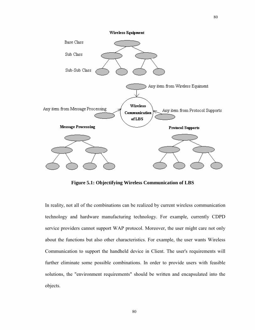
80
80
Figure 5.1: Objectifying Wireless Communication of LBS
In reality, not all of the combinations can be realized by current wireless communication
technology and hardware manufacturing technology. For example, currently CDPD
service providers cannot support WAP protocol. Moreover, the user might care not only
about the functions but also other characteristics. For example, the user wants Wireless
Communication to support the handheld device in Client. The user's requirements will
further eliminate some possible combinations. In order to provide users with feasible
solutions, the "environment requirements" should be written and encapsulated into the
objects.
81
81
5.3 A Framework for Wireless Communication of LBS
5.3.1 Application Domain Analysis
The design of framework must begin with the application domain analysis. A research
team at the University of Calgary has conducted research on the development of an
integrated GPS/GIS/Wireless technology to support Location-Based Services [Gao et al.,
2002; Ramsaran, 2000; Liu et al., 2001]. A number of software programs have been
developed to provide wireless communication solutions to different types of applications
which can be classified into two main application domains: DGPS application domain
and Mobile Equipment Management domain. For DGPS application domain, various data
links were implemented to support differential messages transmission between the base
and rover stations for both code-based and carrier phase-based differential GPS
positioning. For Mobile Equipment Management domain, various data links were
developed to support real-time information transmission for mobile information
management and operational decision-making.
During the development, it has been found that it becomes increasingly inefficient and
even impossible to continuously maintain and update so many applications with rapidly
evolving hardware, software, and protocols in wireless communication. These evolving
technologies require more malleable and open structure software. An Object-Oriented
Application Framework, wireless framework in our case, would offer a promising
solution for these problems. With framework technology, it becomes much more efficient
82
82
to develop software in support of different applications such as precise farming, E-911,
vehicle navigation, geodetic positioning, fleet management, and so on.
Real-time DGPS applications are highly time-critical. For code-based differential GPS
positioning, the latency of RTCM messages on the data link within the range of a few
minutes is required before Selective Availability (SA) was permanently turned off in
May, 2000 [CSI, 2000]. For Real-Time Kinematic GPS positioning, the latency of RTCM
messages on the data link must be within a few seconds [Ashtech, 1999]. Although the
restriction on the latency becomes a little looser after SA was turned off, the loss,
distortion, and delay of the RTCM messages will still seriously deteriorate the
positioning accuracy of GPS positioning. The data throughput of current wireless Internet
systems is still limited. For example, the CDPD service providers only support
approximately 11 Kbits data throughput, and GSM service providers only support 9.6
Kbits data throughput, and the real data throughput rates are not guaranteed. For example,
the data throughput of CDPD service is affected by the number of idle voice channels.
Considering the fact that RTK GPS Positioning requires at least 9.6 Kbits data throughput
to achieve its best performance [Ashtech, 1999], the compression on the correction
RTCM messages is required in order to improve the performance of data link.
Mobile equipment management applications are not so highly time-critical compared to
DGPS applications. But it requires a high reliability on the message transformation since
the field equipment status information is critical for operational decisions. Loss of
information may result in a wrong decision causing significant revenue loss [Ramsaran
83
83
and Gao, 2000]. Although mobile equipment management application domain has
different requirements for the wireless communication data link from DGPS application
domain, many common features can be extracted from them which are also valid for
many other applications. A wireless framework developed based on these features can be
used to support a wide range of Location-Based Services applications.
5.3.2 Wireless Framework Design: Internal Interfaces and Abstract Classes
The internal interfaces of the framework objects can be abstracted to a blackbox with four
elements: two user elements and two object elements. For those two user elements, one is
used to receive users' inputs for transmission to other objects, the other is used to output
the received messages from other objects to users. The blackbox interface will
encapsulate the implementation details of the wireless communication, like how the
message is sent out and how it is received. The two object elements are used to ease the
alliance and cooperation among objects, for example, to combine three objects into one
bigger object. While one is used to send messages to other objects, the other is used to
receive response messages from other objects. The object elements of one object can link
itself to the user elements of another object, so the two objects can merge into one bigger
object. For example, a CDPD object can be linked to one or more objects of Message
Processing, like a compression object and an encryption object. A CDPD object can't be
linked to a Radio object since they are incompatible. However, the objects are not
allowed to connect with each other directly. Instead, they are connected to each other by
the framework or, to be more specific, by the script. The object has to be first connected
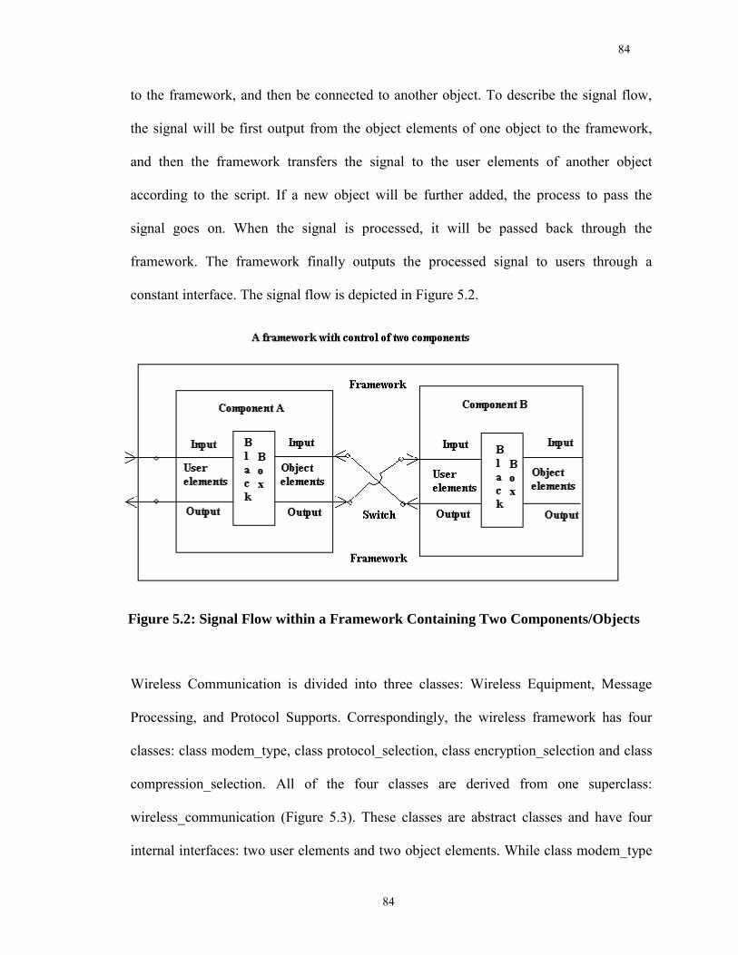
84
84
to the framework, and then be connected to another object. To describe the signal flow,
the signal will be first output from the object elements of one object to the framework,
and then the framework transfers the signal to the user elements of another object
according to the script. If a new object will be further added, the process to pass the
signal goes on. When the signal is processed, it will be passed back through the
framework. The framework finally outputs the processed signal to users through a
constant interface. The signal flow is depicted in Figure 5.2.
Figure 5.2: Signal Flow within a Framework Containing Two Components/Objects
Wireless Communication is divided into three classes: Wireless Equipment, Message
Processing, and Protocol Supports. Correspondingly, the wireless framework has four
classes: class modem_type, class protocol_selection, class encryption_selection and class
compression_selection. All of the four classes are derived from one superclass:
wireless_communication (Figure 5.3). These classes are abstract classes and have four
internal interfaces: two user elements and two object elements. While class modem_type
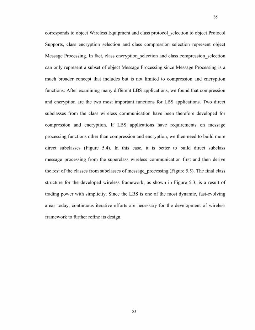
85
85
corresponds to object Wireless Equipment and class protocol_selection to object Protocol
Supports, class encryption_selection and class compression_selection represent object
Message Processing. In fact, class encryption_selection and class compression_selection
can only represent a subset of object Message Processing since Message Processing is a
much broader concept that includes but is not limited to compression and encryption
functions. After examining many different LBS applications, we found that compression
and encryption are the two most important functions for LBS applications. Two direct
subclasses from the class wireless_communication have been therefore developed for
compression and encryption. If LBS applications have requirements on message
processing functions other than compression and encryption, we then need to build more
direct subclasses (Figure 5.4). In this case, it is better to build direct subclass
message_processing from the superclass wireless_communication first and then derive
the rest of the classes from subclasses of message_processing (Figure 5.5). The final class
structure for the developed wireless framework, as shown in Figure 5.3, is a result of
trading power with simplicity. Since the LBS is one of the most dynamic, fast-evolving
areas today, continuous iterative efforts are necessary for the development of wireless
framework to further refine its design.
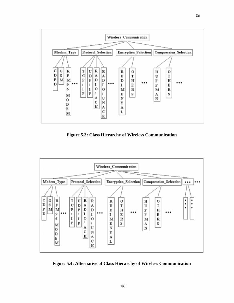
86
86
Figure 5.3: Class Hierarchy of Wireless Communication
Figure 5.4: Alternative of Class Hierarchy of Wireless Communication
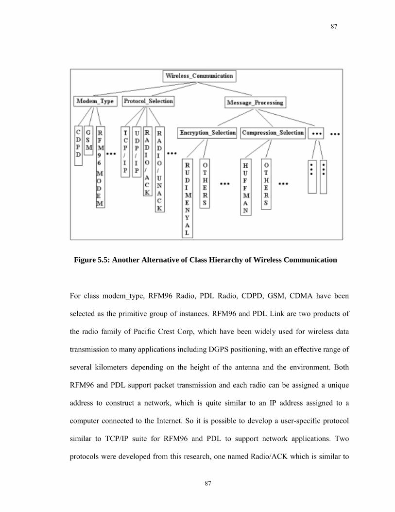
87
87
Figure 5.5: Another Alternative of Class Hierarchy of Wireless Communication
For class modem_type, RFM96 Radio, PDL Radio, CDPD, GSM, CDMA have been
selected as the primitive group of instances. RFM96 and PDL Link are two products of
the radio family of Pacific Crest Corp, which have been widely used for wireless data
transmission to many applications including DGPS positioning, with an effective range of
several kilometers depending on the height of the antenna and the environment. Both
RFM96 and PDL support packet transmission and each radio can be assigned a unique
address to construct a network, which is quite similar to an IP address assigned to a
computer connected to the Internet. So it is possible to develop a user-specific protocol
similar to TCP/IP suite for RFM96 and PDL to support network applications. Two
protocols were developed from this research, one named Radio/ACK which is similar to
88
88
TCP/IP, and the other named Radio/UNACK which is similar to UDP/IP. While
Radio/ACK provides a mechanism to acknowledge the user at the sending side if the
messages have been received by the user at the receiving side, Radio/UNACK does not
provide such a mechanism. The field test results demonstrated that Radio/ACK worked
well for applications with high security demand such as Mobile Equipment Management
System, and Radio/UNACK worked well for applications with highly time-sensitive
demand such as RTK positioning.
CDPD can support both TCP/IP and UDP/IP, and test results indicate CDPD can support
applications with high demand of security and time-sensitivity [Liu et al., 2001]. The
CDPD is well encapsulated by the underlying operating system, and the application
developers need not care about any implementation detail. Compared to fixed Internet,
CDPD has a much-limited data throughput. CDPD currently can only provide a data
throughput at about 11 Kbits per second and thus is not adequate to support multi-media
applications. Despite the bandwidth issue, there is no difference between the application
design for CDPD and that for fixed Internet, thus the programs designed for fixed
Internet can be used for CDPD without modification, and vice versa. In fact, after
encapsulation by the underlying operating system, the wireless Internet, such as CDPD,
GSM, and CDMA, will provide the same interface as the fixed Internet to the application
developers, and the programs designed for CDPD can be used by GSM, CDMA, and the
fixed Internet without modification or with only slight modification. However, although
CDPD, GSM and CDMA can provide a similar wireless Internet interface to the
application developers, there is still some difference among them. While CDPD is based
89
89
on AMPS, GSM and CDMA belong to 2G which is based on digital communication. For
example, GSM can support SMS (Short Message Service), which can be used to develop
cost-efficient applications. In the future, new features will be brought into the class GSM
and CDMA to support LBS applications better.
For class protocol_selection, TCP/IP, UDP/IP, Radio_ACK, Radio_UNACK, and WAP
were carefully chosen as the primitive group of instances. As mentioned before, TCP/IP
and UDP/IP are supported by CDPD, GSM and CDMA, while Radio_ACK,
Radio_UNACK are supported by RFM96 and PDL Radio. WAP (Wireless Application
Protocol) is a protocol specially designed for devices with low bandwidth and small
screen. Currently WAP is still at its early stage and has not gotten much popularity yet.
Although CDPD cannot support WAP at this moment, our CDPD provider has the
intention to support it in the near future. Considering WAP has the potential to get into
the mainstream of the protocols for LBS applications in the future, we leave WAP as a
potential choice for our framework but the implementation work will be done in the
future.
For class encryption_selection, we provide an instance named Rudimental encryption
method. For class compression_selection, we provide an instance named Huffman
compression method. The Rudimental encryption method can apply a key to the text
information so that the encrypted information cannot be recovered without the key.
Huffman compression can compress the volume of information to about 70 percent of its
original size. The available choices that the framework provides are not rich, and the
90
90
wireless framework is at its embryonic form, still on the way from an idea to a product.
The emergence of the wireless framework indicates the beginning of the work rather than
the end. Although the wireless framework is far from fledged at this stage, it has been
applied in two different types of application domains, and the results are inspiring.
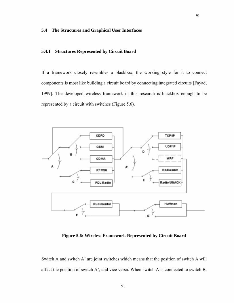
91
91
5.4 The Structures and Graphical User Interfaces
5.4.1 Structures Represented by Circuit Board
If a framework closely resembles a blackbox, the working style for it to connect
components is most like building a circuit board by connecting integrated circuits [Fayad,
1999]. The developed wireless framework in this research is blackbox enough to be
represented by a circuit with switches (Figure 5.6).
Figure 5.6: Wireless Framework Represented by Circuit Board
Switch A and switch A� are joint switches which means that the position of switch A will
affect the position of switch A�, and vice versa. When switch A is connected to switch B,
92
92
which means one of CDPD, GSM, and CDMA is chosen, switch A� has to be connected
to switch D, which means only TCP/IP, UDP/IP, and WAP can be chosen since they can
be supported by wireless Internet but Radio/ACK and Radio/UNACK cannot. When
switch A is connected to switch C, which means either RFM96 or PDL Radio is chosen,
switch A� has to be connected to switch E, which means only Radio/ACK or
Radio/UNACK can be chosen since these protocols are specially designed for wireless
radio but not for wireless Internet. The compression and encryption functions are
independent of the modems and protocols, so there is no need to apply joint switches for
compression and encryption components. Switch F and switch G allow application
developers to decide if to use compression or encryption function. The script is
determined by the status of the switches. Application developers can set the script with
the Graphical User Interface (GUI) provided by the wireless framework. The GUI also
provides an explicit indication for the status of the switches.
5.4.2 Graphical User Interfaces
Graphical User Interfaces are an important part that the wireless framework provides to
the application developers. With Graphical User Interfaces, the application developers
can set up the script easily by just clicking a few radio buttons (Figure 5.7). The GUI also
provides a graphical representation of the script to the application developers. The
application developers can choose to combine the GUI with the final interface provided
to the users, or choose to hide it by constructing a new GUI for the users. The new GUI
may provide a more customized interface than the framework GUI. However, the choices
93
93
from the users will be finally received by the wireless framework and represented by the
script.
The GUI of the wireless framework is composed of two parts: the primary interface and
the secondary interface. While the primary interface presents an explicit indication for the
status of the switches in the virtual circuit board of the wireless framework, the secondary
interface allows the application developers to configure some more advanced attributes of
the wireless data link, such as the IP addresses, port addresses, or radio addresses for both
local and remote machines. The configuration via the second interface will be written to
the script. The primary interface is shown in Figure 5.7. The primary interface is
composed of three parts: a Menu, four groups of radio buttons, and two command
buttons. The Menu allows application developers to configure the data link with default
values, and can provide version information and context helps on the wireless framework.
The four groups of radio buttons provide the application developers an intuitive way to
configure the data link. The radio buttons in each group are exclusive, which means only
one button can be selected in each group. For example, if CDPD is chosen in group
Modem Selection, the previous choice in this group will be cleared. Since we currently
have not tested GSM and CDMA for the wireless framework, GSM Modem and CDMA
Modem are disabled in the Modem Selection group. The same applies to WAP in the
Protocols Selection group. If either RFM96 Radio Modem or PDL Radio Modem is
chosen in group Modem Selection, there are only two choices, Radio/ACK and
Radio/UNACK, available in group Protocols Selection, with TCP/IP and UDP/IP
disabled. If CDPD Modem is chosen in group Modem Selection, there are also two
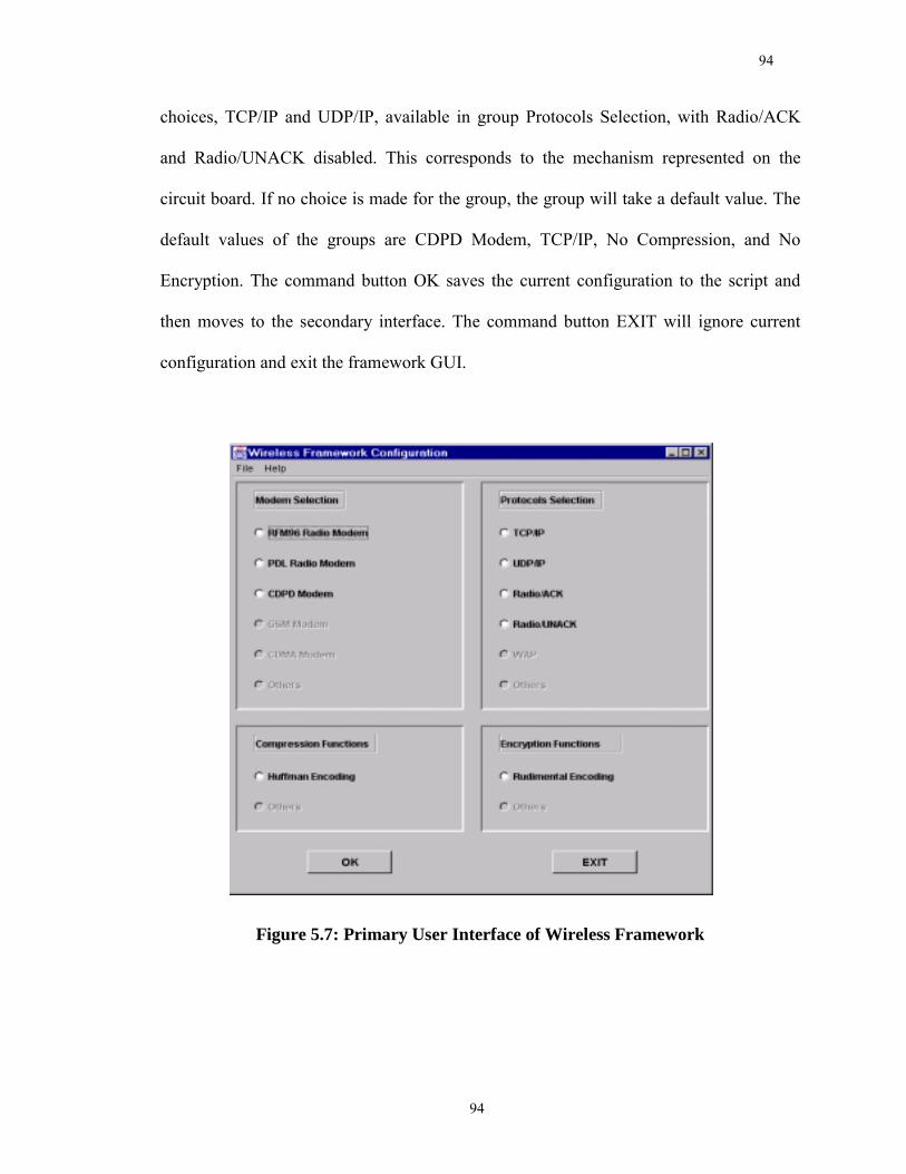
94
94
choices, TCP/IP and UDP/IP, available in group Protocols Selection, with Radio/ACK
and Radio/UNACK disabled. This corresponds to the mechanism represented on the
circuit board. If no choice is made for the group, the group will take a default value. The
default values of the groups are CDPD Modem, TCP/IP, No Compression, and No
Encryption. The command button OK saves the current configuration to the script and
then moves to the secondary interface. The command button EXIT will ignore current
configuration and exit the framework GUI.
Figure 5.7: Primary User Interface of Wireless Framework
95
95
The secondary interface is shown in Figure 5.8. The secondary interface is composed of
three parts: a Menu, two groups of labels, textfields, and comboboxes for configuration,
and two command buttons. The Menu functions are similar to those of the primary
interface. The group at the left side is designed to configure wireless Internet, while the
other at the right side to configure wireless radio. Application developers can choose one
of them depending on their choices at the primary interface. The upper part of group
wireless Internet contains two textfields to set IP addresses for both local and remote
machines. Sometimes the computer name can be used to replace the IP address for
convenience. The lower part of group wireless Internet contains two textfields to set Port
addresses for both local and remote machines. The socket program, which is used to
support communication between the local machine and remote machine, needs both the
IP and Port addresses of both local and the remote machines to build a connection. The
default values for IP and Port addresses are displayed in the text fields. It is the
responsibility of either the application developers or the users to find available port
addresses to avoid collision with other programs. Similar to the wireless Internet group,
the upper part of the Wireless Radio group is used to set the addresses for both local and
remote modems. The address can be set to any number from 1 to 254 since address 0 and
address 255 are used for special purpose. The lower part of group Wireless Radio is used
to adjust the modems to adapt their environment with noisy radio waves. When Low is
selected, the wireless radio has a longer effective range, but is prone to the noise and thus
the receiver modem can get wrong data. When High is selected, the ability for wireless
radio to resist noise is strengthened but the effective range of wireless radio is shortened.
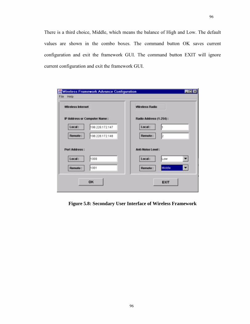
96
96
There is a third choice, Middle, which means the balance of High and Low. The default
values are shown in the combo boxes. The command button OK saves current
configuration and exit the framework GUI. The command button EXIT will ignore
current configuration and exit the framework GUI.
Figure 5.8: Secondary User Interface of Wireless Framework
97
97
Chapter 6
Application and Test Results: Mobile Equipment Management
The best way to evaluate the performance of a framework is to test the applications based
on the framework. In order to evaluate the wireless framework, the developed framework
has been applied to the development of two different LBS applications, namely, a Mobile
Equipment Management System (MEMS) and a Wireless Internet-Based Real-Time
Kinematic (RTK) GPS Positioning System. The concept, implementation, test methods,
and results of MEMS are described in this chapter.
6.1 Mobile Equipment Management
In the past few years, the combination of technologies and business opportunities has
created a rapidly emerging area known as Mobile Equipment Management System
(MEMS). MEMS applications are typical LBS applications with distinct Client, Server,
and Wireless Communication parts. The potential application of MEMS are numerous
and the followings are just a few examples: oil exploration, fleet management, public
utilities, transportation, emergency response, and other applications of remote asset
management and operation of unattended facilities [Webcom, 2001]. By protecting its
facilities, inventory and other physical assets, nearly any company in any industry, even a
private homeowner, can reap the benefits of a Mobile Equipment Management System.
98
98
Whether expressed in real dollars or the less-tangible peace of mind, MEMS helps affect
the bottom line significantly [DeFusco, 2001].
6.1.1 Concept of MEMS
A MEMS system is usually involved the use of several cutting-edge technologies today:
GPS (Global Positioning Satellite System), GIS (Geographical Information System),
Wireless Communication, Internet, DBMS (Database Management System), PDA
(Personal Computation Device Assistant) and others. Although MEMS is getting more
and more popular with those fast-evolving technologies and fast-growing application
fields foresaid, there is lack of a rigid definition of MEMS. MEMS is not a centralized
data collection system; rather it is an open integrated network of events that, when
followed, increase productivity [Ramsaran, 2000]. Generally speaking, MEMS is
comprised primarily of three main systems as shown in Figure 5.1 [Ramsaran, 2000; Liu,
et al., 2001], namely:
· Data acquisition
· Communication system
· Office system
Obviously, the three-system structure of MEMS is quite similar to the three-part structure
of LBS applications. In fact, MEMS applications are typical LBS applications. While
Data acquisition corresponds to Client, Office system to Server, and Communication
99
99
system to Wireless Communication. The Data acquisition system is designed to collect
both spatial and non-spatial information on the spot. The Data acquisition system should
cut down on human errors as much as possible. It can be either manned or unmanned,
like remote alarm system. The Communication system, mostly wireless communication,
is responsible to transfer the information from the Data acquisition system to Office
system with high security. The Office system will process, manage, and organize the
information via DBMS and perform various functions such as Management,
Maintenance, Scheduling, and Decision-Making on DBMS according to the users�
demand.
An open structure should be employed in the development of a MEMS in order for the
system to incorporate new technologies and tools in satellite navigation, GIS, information
management and wireless communications as shown in Figure 6.1. Applying wireless
framework will help MEMS achieve open structure and incorporate new wireless
technologies.
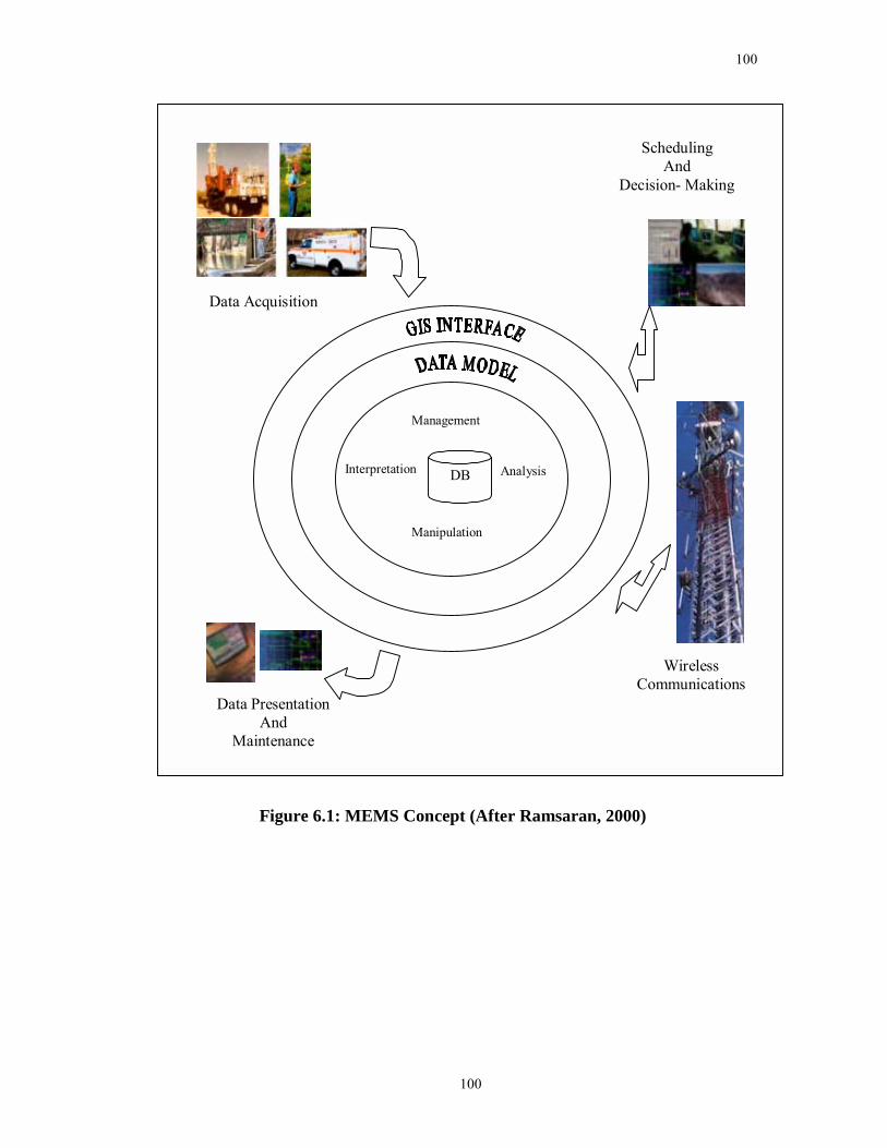
100
100
Manipulation
Management
Analysis
Data Acquisition
Data PresentationAnd
Maintenance
SchedulingAnd
Decision- Making
WirelessCommunications
Interpretation DB
Figure 6.1: MEMS Concept (After Ramsaran, 2000)
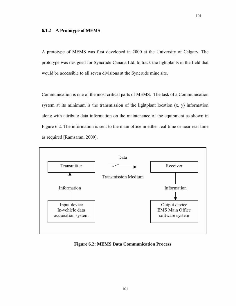
101
101
6.1.2 A Prototype of MEMS
A prototype of MEMS was first developed in 2000 at the University of Calgary. The
prototype was designed for Syncrude Canada Ltd. to track the lightplants in the field that
would be accessible to all seven divisions at the Syncrude mine site.
Communication is one of the most critical parts of MEMS. The task of a Communication
system at its minimum is the transmission of the lightplant location (x, y) information
along with attribute data information on the maintenance of the equipment as shown in
Figure 6.2. The information is sent to the main office in either real-time or near real-time
as required [Ramsaran, 2000].
Input deviceIn-vehicle data
acquisition system
Output deviceEMS Main Officesoftware system
Transmitter Receiver
Information Information
Transmission Medium
Data
Figure 6.2: MEMS Data Communication Process
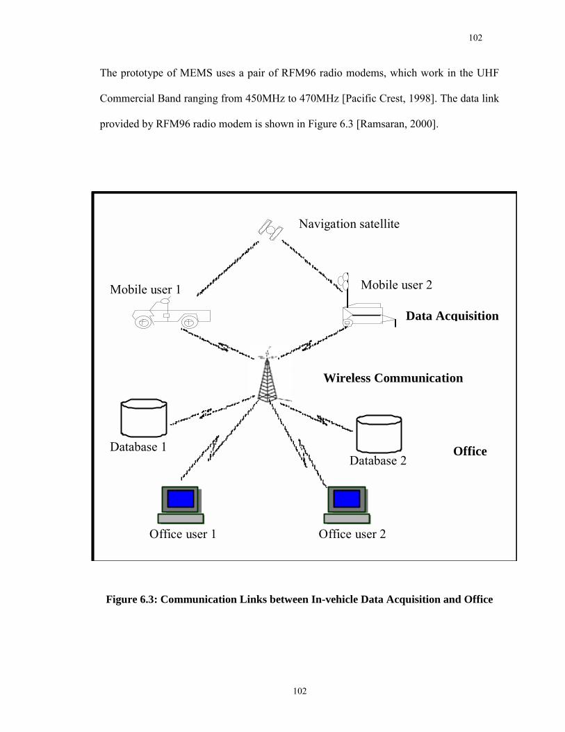
102
102
The prototype of MEMS uses a pair of RFM96 radio modems, which work in the UHF
Commercial Band ranging from 450MHz to 470MHz [Pacific Crest, 1998]. The data link
provided by RFM96 radio modem is shown in Figure 6.3 [Ramsaran, 2000].
Figure 6.3: Communication Links between In-vehicle Data Acquisition and Office
Wireless Communication
Navigation satellite
Data Acquisition
Mobile user 1
Office user 1 Office user 2
Database 1
Mobile user 2
Database 2 Office
103
103
6.2 Implementation of Wireless Framework for MEMS
The fast evolving technology makes MEMS less possible to be bound to a stable
communication method. It seems inevitable that MEMS will have to support various
communication methods in the future. Moreover, software reuse needs to be promoted to
benefit the development of similar LBS applications in the future.
The wireless framework can be used to empower MEMS to support various
communication methods and provide customer solution to the users. One Radio-based
Communication system, and one CDPD-based Communication system respectively, were
developed using the wireless framework to serve the users. The Radio-based
Communication system uses a pair of RFM96 radio modems, which takes digital
information from the in-vehicle data acquisition system, transforming it into analog
waveform, and the signal is transmitted via radio waves to the Office. Radio_ACK
protocol is adopted to provide a reliable data link between the modems. Once a modem
receives a message from the modem at another site, and the message is proved complete
by passing the checksum examination, the modem will send an acknowledge information
back to the modem at the first site. If for some reason the modem at the first site does not
receive the acknowledgement, it will save the messages to a temporary file, and
retransmit it again later after a fixed interval. The messages kept in the temporary file will
be transmitted again and again until an acknowledgement is received, which confirms
that the message has been received successfully by the modem at the second site.
Moreover, a rudimental encryption algorithm, supported by the developed wireless
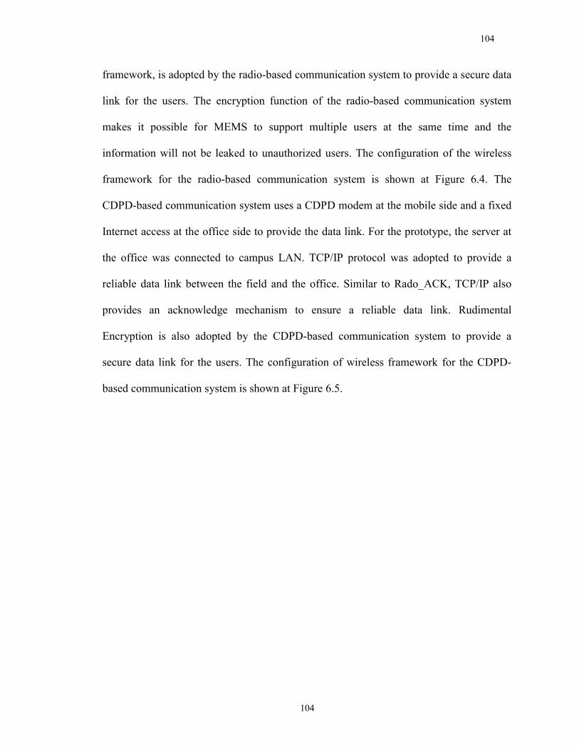
104
104
framework, is adopted by the radio-based communication system to provide a secure data
link for the users. The encryption function of the radio-based communication system
makes it possible for MEMS to support multiple users at the same time and the
information will not be leaked to unauthorized users. The configuration of the wireless
framework for the radio-based communication system is shown at Figure 6.4. The
CDPD-based communication system uses a CDPD modem at the mobile side and a fixed
Internet access at the office side to provide the data link. For the prototype, the server at
the office was connected to campus LAN. TCP/IP protocol was adopted to provide a
reliable data link between the field and the office. Similar to Rado_ACK, TCP/IP also
provides an acknowledge mechanism to ensure a reliable data link. Rudimental
Encryption is also adopted by the CDPD-based communication system to provide a
secure data link for the users. The configuration of wireless framework for the CDPD-
based communication system is shown at Figure 6.5.

105
105
Figure 6.4: Configuration of Wireless Framework for the Radio-based
Communication System
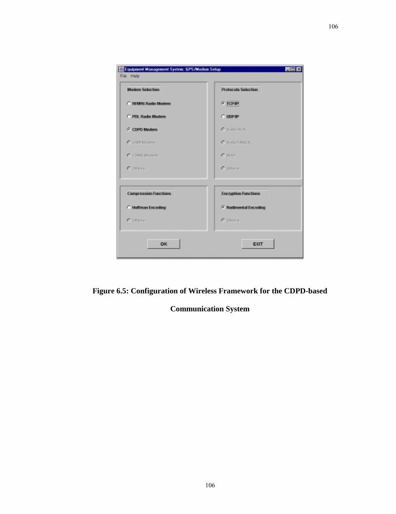
106
106
Figure 6.5: Configuration of Wireless Framework for the CDPD-based
Communication System
107
107
6.3 Field Test and Results
Testing of the CDPD-Based Mobile Equipment Management System was conducted on
July 9, 2001, in Calgary, while testing of the Radio-Based Mobile Equipment
Management System was conducted on Oct. 28, 2001. The Data Acquisition System was
installed on a vehicle which was driven around the campus of the University of Calgary.
6.3.1 Test Details and Results of Radio-Based MEMS
A field test was conducted in Calgary on Oct. 28, 2001. The server part of the Mobile
Equipment Management System was set on the roof of the Engineering Building at the
University of Calgary. The client part of the Mobile Equipment Management system was
set in a vehicle. The server comprised a desktop computer with Pentium II inside, two
serial ports with one serial port connected to RFM96 radio modem, and Windows NT4.0
OS. The client system was comprised a Toshiba Laptop with Windows NT4.0 OS, four
serial ports generated by a SSP-100 PCMCIA card with one connected to a Javad Legacy
dual frequency GNSS receiver and another connected to a RFM96 radio modem, and a
battery power supply. The Javad Legacy receiver can provide a horizontal positioning
accuracy usually better than 10m after SA is turned off when in stand-alone mode.
A total of 100 points were collected on the streets in Calgary and were sent back to the
server in real time. The server part of the Mobile Equipment Management System
received data transmitted from the client and displayed the vehicle's locations on a digital
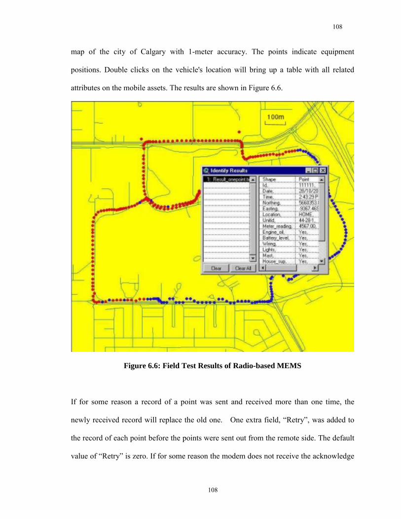
108
108
map of the city of Calgary with 1-meter accuracy. The points indicate equipment
positions. Double clicks on the vehicle's location will bring up a table with all related
attributes on the mobile assets. The results are shown in Figure 6.6.
Figure 6.6: Field Test Results of Radio-based MEMS
If for some reason a record of a point was sent and received more than one time, the
newly received record will replace the old one. One extra field, �Retry�, was added to
the record of each point before the points were sent out from the remote side. The default
value of �Retry� is zero. If for some reason the modem does not receive the acknowledge
109
109
information from the office server after sending, the record for that point will be saved to
a temporal file with �Retry� set to one, and retransmit it again after a fixed interval. The
value of �Retry� can be used to indicate if the modems fail to communicate with each
other mostly due to out of effective range. The red points in Figure 6.6 indicate that the
values of "Retry" are zeros, while the blue points indicate that the values of "Retry" are
ones, which indicate that the corresponding records are retransmitted. Figure 6.6 shows
the approximate effective range of this Radio-Based MEMS. It is possible to enhance the
system further by increasing the radio antenna height and the transmission power.
A comparison made between the database at the client and the database at the server
showed that there was no record lost or changed. The results indicated that the Radio-
based Mobile Equipment Management prototype built upon the Wireless Framework
worked reliably.
6.3.2 Test Details and Results of CDPD-Based MEMS
A field test was conducted in Calgary on July 9, 2001. The server part of Mobile
Equipment Management System was set up in the Geomatics Trailor at the University of
Calgary and the client part of Mobile Equipment Management system was installed in a
vehicle. The server comprised a desktop computer with Pentium II inside, a fixed Internet
access via campus LAN, and Windows NT4.0 OS, while the client comprised a Toshiba
Laptop with Windows NT4.0 OS, a wireless Internet access via CDPD modem, one serial
port connected to a Javad Legacy dual frequency GNSS receiver, and a battery for power
110
110
supply. The data acquisition software installed in the laptop at the remote side was
designed to collect and transmit the position and status information of the equipment.
The interface of the software is similar to that of Radio-Based MEMS.
100 points were collected and the results are shown in Figure 6.7. The �Retry� values of
these 100 points are shown in Figure 6.7, which indicates that no retransmission
occurred.
Comparing the database at the client part with the database at the server part indicated
that there was no record lost or being changed. The results indicated that the CDPD-
based Mobile Equipment Management prototype built upon the Wireless Framework
worked reliably.
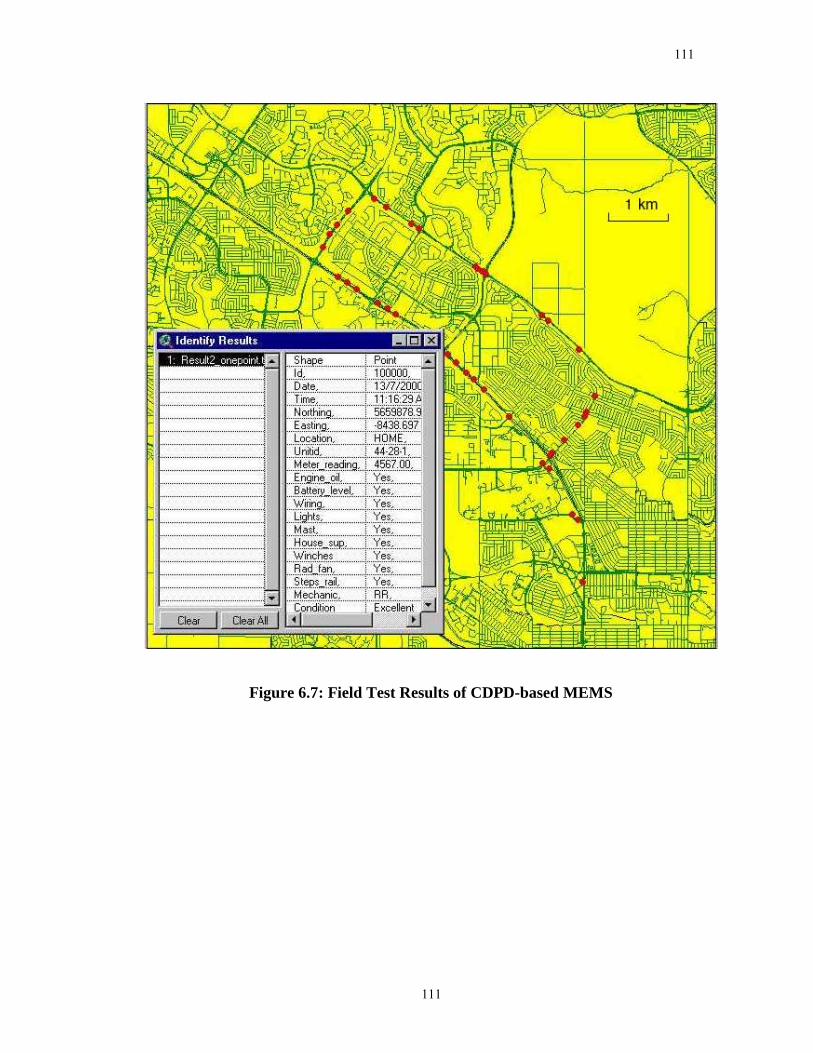
111
111
Figure 6.7: Field Test Results of CDPD-based MEMS
112
112
Chapter 7
Application and Test Results:
Wireless Internet-Based RTK GPS Positioning
An Internet-based RTK System has been developed based on the wireless framework
developed for this research and the test results are described in this chapter.
7.1 Concept of Wireless Internet-Based RTK GPS Positioning
Real Time Kinematic (RTK) is a satellite-based positioning and navigation technology
developed in the early 1990s allowing the centimeter level positioning of a stationary or
moving platform in real time [Gao et al., 2002]. Because RTK technology is able to
provide the highest position accuracy possible from a satellite navigation system in real-
time, the technology has since then received wide applications in geodetic positioning
and other areas.
Real-Time Kinematic GPS positioning is essentially a special form of differential
positioning. RTK can achieve centimeter-level positioning accuracy using a carrier phase
differential method [Zhodzishsky et al., 1998; Namie et al., 1999]. Conventionally, RTK
GPS positioning employs a pair of receivers and radio modems at each end of the
baseline, that is, at both base station and rover station. The data collected at the base
receiver are transmitted by the base radio modem to the rover radio. The rover GPS
113
113
receiver receives the base measurements via the radio modem and extrapolates them to
the same epoch at which the rover measurements have been made for a more precise
position determination. A RTK positioning system also consists of three parts: Client
(rover), Server (base), and Wireless Communication (data link). The traditional RTK
GPS positioning method, however, has to be conducted over reasonably short baselines,
because GPS errors become less spatially correlated over longer baselines, causing
degradation in the resulting positioning accuracy [Gao et al, 1997]. The maximum
baseline length of the traditional RTK GPS positioning method is also often further
shorten by the effective range of the wireless communication system adopted for the data
link.
Due to the fast advances in wireless communication technology, the Internet has become
one of the most important communication methods today [Nguyen, 2001]. Some
investigations have been made to use the Internet for GPS applications. In Muellerschon
et al (2000 and 2001) and Hada et al. (2000), the wireless Internet has been proposed for
distributing global GPS-based differential corrections. Lee et al. (2000) have investigated
an Internet-based differential GPS system for mobile communication users. It is expected
that the wireless Internet will be increasingly used in the future as an efficient
communication alternative to conventional radio-based methods. The wireless Internet
has many advantages over conventional radio data transmission methods for RTK
positioning and navigation [Gao et al, 2002].
114
114
First, the wireless Internet has wide coverage. The Internet is a global network and its
transmission range is not constrained by physical factors. The wireless telephone
systems, AMPS/CDPD (Advance Mobile Phone Service/Cellular Digital Packet Data)
and GSM (Global System for Mobile), the two most common and dominant systems
applied to the wireless Internet in Europe and North America, keep expanding daily and
are evolving into global networks. CDPD technology was adopted in our prototype
because the coverage of CDPD is larger than that of GSM [CTIA, 1999; GSM World,
2001; Virginia Tech 2000]. Second, data transmission via the wireless Internet is much
more reliable than that via the wireless radio modem. For example, CDPD is a packet-
switched data service that uses the existing AMPS network to transmit data at a rate of
19.2 kbps. In AMPS, a dense transmission tower network is built to keep a constant
signal power and the cellular technology is used to assign the neighbor transmission
towers with different frequencies to avoid frequency collision. Moreover, to minimize
cross-channel interferences, the channel separation is set to 30KHz, which is much larger
than the channel separation in UHF commercial band [Lin, 2001; Wong et al., 1995].
Although it can be assigned to a dedicated RF channel, CDPD differs in that it transmits
packet data over idle cellular voice channels, and automatically switches to another
channel when the current channel is about to be assigned for voice usage, thus greatly
improving the efficiency and reducing the costs of data transferring [Lin, 2001]. In
addition, the Internet-based RTK base station has the potential to serve as a virtual base
station whose data is accessible to a large number of rover users and in a variety of
modes.
115
115
7.2 Implementation of Wireless Framework for Internet-Based RTK
To minimize data transmission latency and its subsequent influence on the RTK
positioning accuracy, the Internet protocols, which define how the data are transmitted
through the Internet, should be selected carefully. The Internet currently uses a
Transmission Control Protocol/Internet Protocol (TCP/IP) suite to connect all networks,
organizations and users across the world. Transmission Control Protocol (TCP) and the
User Datagram Protocol (UDP) are two important transport protocols that have been
widely used for Internet applications.
The TCP provides a stream delivery and virtual connection service to applications
through the use of sequenced acknowledgment with retransmission of packets while the
UDP provides a simple message delivery for transaction-oriented services with no
acknowledgement of delivery. The TCP is able to provide highly reliable data
transmission since it ensures reliability, flow control, and connection maintenance. As a
price for the reliability, the TCP may not be suitable for real-time applications like RTK
positioning because it requires an acknowledgement of data arrival and any lost data must
be sent again [Hada et al., 1999; Liu et al., 2001]. The UDP is able to provide faster data
transmission. But, there may be loss of data using the UDP because there is no
acknowledgement of delivery. Since fast differential data transmission is essential for the
success of a RTK system in deriving centimeter accurate positions, the UDP protocol has
been utilized in this research to test the performance of the developed Internet-based
RTK system.
116
116
To achieve best positioning accuracy, the latency of RTCM messages should be
minimized. The slowest rate at which one should send RTCM messages for RTK is once
every 5 seconds. Remote receivers can fix integers with base station data arriving once
every 5 seconds or faster [Magellan, 1998]. To send RTCM correction messages (mainly
type 18 and type 19 messages) once every second, the minimum bandwidth requirements
for RTK positioning is 9600 bps. Considering that the latency assessment for RTCM
messages needs additional bandwidth and that the bandwidth that CDPD service can
provide is not constant during the day, the total bandwidth requirements will be quite
close to the maximum bandwidth CDPD service can offer. Thus a compression operation
on RTCM messages is required. The compression algorithm offered by Wireless
Framework is called Huffman Encoding. The wireless framework can provide a
maximum compression ratio up to 8:5 for RTCM messages without information
distortion. Two wireless Internet-Based RTK GPS Positioning applications, one with
compression function and the other without, were built with the developed wireless
framework. The configuration of the system with compression function is shown in
Figure 7.1. For the system without compression function, the option for compression
function in the main GUI interface of the platform should be unchecked.
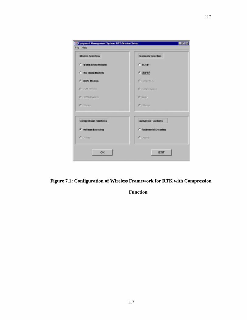
117
117
Figure 7.1: Configuration of Wireless Framework for RTK with Compression
Function
118
118
7.3 Field Tests and Results
The field tests on the wireless Internet-Based RTK GPS positioning with and without
RTCM messages compression were conducted on June 26th, 2002 in Calgary. The tests
were designed to test the whole wireless Internet-Based RTK GPS positioning system but
only the results related to the wireless framework are analyzed in the following.
7.3.1 Field Test Results of Wireless Internet-based RTK GPS Positioning Without
RTCM Messages Compression
The field test of wireless Internet-based RTK GPS positioning without RTCM messages
compression was carried on June 26th, 2002. Two Ashtech GPS+GLONASS single
frequency receivers were used as the base and rover receivers. Two regular geodetic
antennae were used as the base and rover antennae. The base antenna was setup on a
pillar whose coordinates were precisely known. The rover antenna was mounted on the
roof of a vehicle. The base station comprised the base receiver and antenna, a desktop
computer with Pentium II inside, one serial port to receive RTCM messages, also called
differential RTK data, from the base receiver, another serial port to log GPS NMEA data
and raw data, a fixed Internet access via campus LAN, and Windows NT4.0 OS. The
rover comprised the rover receiver and antenna, a Toshiba Laptop with Windows NT4.0
OS, a wireless Internet access via CDPD modem, one serial port to send RTCM messages
to the rover receiver, another serial port to log GPS NMEA data and raw data, and a
battery for power supply. A socket program on the server computer collected the RTCM
119
119
messages from the base receiver and made it available on the Internet. The rover receiver
was connected to a Toshiba SatelliteTM Laptop with a CDPD modem. Since the CDPD
modem could provide a wireless Internet access via CDPD, the rover receiver could
receive RTCM messages from the base station via the wireless Internet, thus the data link
was built. The base station was set in Satellite Lab of the Engineering building at the
University of Calgary and the rover was set in a vehicle. The field test was carried out on
the highway with baselines greater than 10 kilometers. During the test, the rate of the
RTCM messages output of the base receiver was set to 1 Hz and the real-time RTK
position results were compared with the post-processing results.
Data transmission latency is defined as the difference between the departure time of the
differential RTK data leaving the base receiver and the arrival time of the same data
reaching the rover receiver. Data transmission latency can affect the accuracy of the RTK
positioning. To evaluate the data transmission latency over the wireless Internet, a
program was developed to calculate the round-trip time latency: A timestamp was first
sent to the rover station from the base station, and once the timestamp reached its
destination, the rover station sent the timestamp back to the base station without delay.
Then the base station calculated the round-trip time delay by comparing the timestamp
with current system time. The data transmission latency of the differential RTK data is
about half of the round-trip time latency. Usually this assumption is valid for latency
detection. The round-trip time latency results of the RTK test are shown in Figure 7.2
where the maximum latency is 15.24 seconds and the minimum is 0.97 seconds. The
average latency is 2.02 seconds. These latency results are consistent with the results
120
120
obtained by JPL [Muellweschoen et al., 2001] which has shown that 95% of the data
from global reference stations can be returned to the processing center is less than 3
seconds.
Figure 7.3 shows the PDOP (Position Dilution of Precision) values and the number of
satellites visible during the field test. PDOP was in the range from 1.7 to 2.4 and the
number of visible satellites varied between 8 and 9. The position errors are obtained by
comparing the results of the field RTK test with the results of a commercial post-
processing software package. Figure 7.4 shows the position errors. The statistical values
of the three coordinate components were given in Table 7.1. It was clearly seen that the
maximum real-time positioning error was less than 15cm for all coordinate components.
The majority of the data indicate a difference of less than 10 centimeters between the
post-processing results and the field RTK position results.
Figure 7.4 indicated that the positioning errors from GPS time 362900 to 362930 seconds
were relatively larger than the rest of data points. The positioning modes of the position
solutions are shown in Figure 7.5. From the figure, we notice that the position results
were derived from float-ambiguity positioning mode for the periods of GPS time 362900
to 362930 during which greater positioning errors have been demonstrated. In RTK
positioning, float-ambiguity position solutions will be provided if the carrier phase
integer ambiguities cannot be fixed. As a result, the obtained position solutions will be
degraded to accuracy in the range of decimetre to metre level. Successful integer
ambiguity fixing relies on a number of factors such as smaller observation noise level,
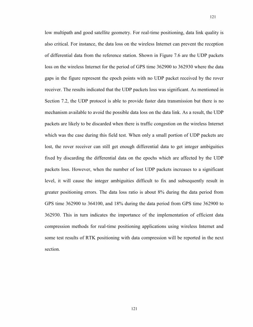
121
121
low multipath and good satellite geometry. For real-time positioning, data link quality is
also critical. For instance, the data loss on the wireless Internet can prevent the reception
of differential data from the reference station. Shown in Figure 7.6 are the UDP packets
loss on the wireless Internet for the period of GPS time 362900 to 362930 where the data
gaps in the figure represent the epoch points with no UDP packet received by the rover
receiver. The results indicated that the UDP packets loss was significant. As mentioned in
Section 7.2, the UDP protocol is able to provide faster data transmission but there is no
mechanism available to avoid the possible data loss on the data link. As a result, the UDP
packets are likely to be discarded when there is traffic congestion on the wireless Internet
which was the case during this field test. When only a small portion of UDP packets are
lost, the rover receiver can still get enough differential data to get integer ambiguities
fixed by discarding the differential data on the epochs which are affected by the UDP
packets loss. However, when the number of lost UDP packets increases to a significant
level, it will cause the integer ambiguities difficult to fix and subsequently result in
greater positioning errors. The data loss ratio is about 8% during the data period from
GPS time 362900 to 364100, and 18% during the data period from GPS time 362900 to
362930. This in turn indicates the importance of the implementation of efficient data
compression methods for real-time positioning applications using wireless Internet and
some test results of RTK positioning with data compression will be reported in the next
section.
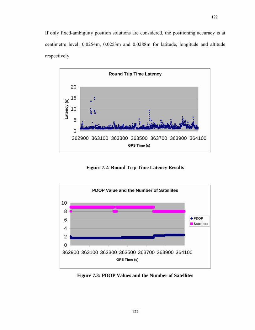
122
122
If only fixed-ambiguity position solutions are considered, the positioning accuracy is at
centimetre level: 0.0254m, 0.0253m and 0.0288m for latitude, longitude and altitude
respectively.
Round Trip Time Latency
0
5
10
15
20
362900 363100 363300 363500 363700 363900 364100GPS Time (s)
Late
ncy
(s)
Figure 7.2: Round Trip Time Latency Results
PDOP Value and the Number of Satellites
02468
10
362900 363100 363300 363500 363700 363900 364100GPS Time (s)
PDOPSatellites
Figure 7.3: PDOP Values and the Number of Satellites
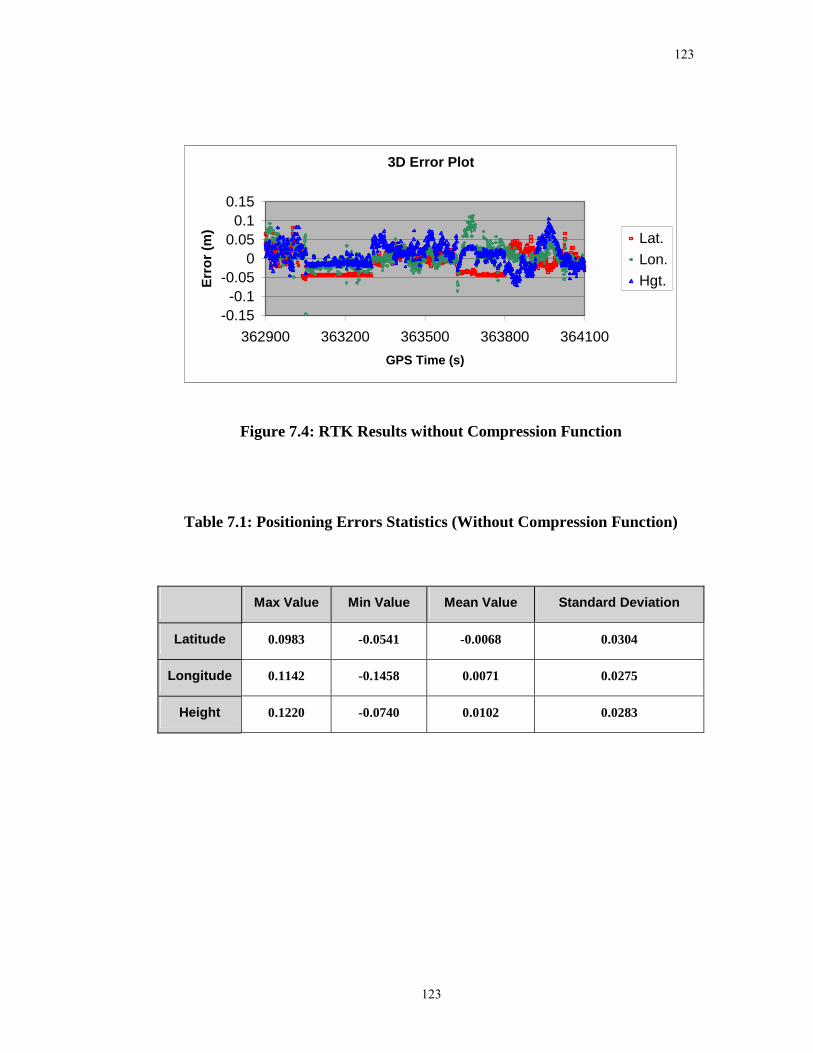
123
123
3D Error Plot
-0.15-0.1
-0.050
0.050.1
0.15
362900 363200 363500 363800 364100GPS Time (s)
Erro
r (m
) Lat.Lon.Hgt.
Figure 7.4: RTK Results without Compression Function
Table 7.1: Positioning Errors Statistics (Without Compression Function)
Max Value Min Value Mean Value Standard Deviation
Latitude 0.0983 -0.0541 -0.0068 0.0304
Longitude 0.1142 -0.1458 0.0071 0.0275
Height 0.1220 -0.0740 0.0102 0.0283
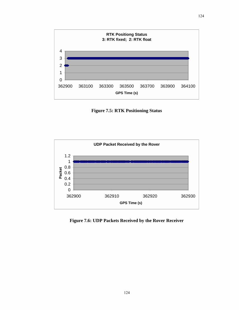
124
124
RTK Positiong Status3: RTK fixed; 2: RTK float
01234
362900 363100 363300 363500 363700 363900 364100GPS Time (s)
Figure 7.5: RTK Positioning Status
UDP Packet Received by the Rover
00.20.40.60.8
11.2
362900 362910 362920 362930GPS Time (s)
Pack
et
Figure 7.6: UDP Packets Received by the Rover Receiver
125
125
7.3.2 Field Test Results of Wireless Internet-based RTK GPS Positioning with
RTCM Messages Compression
The field test of wireless Internet-based RTK GPS positioning with RTCM messages
compression was held on June 26th, 2002. The equipment and test methods used for RTK
GPS positioning with RTCM messages compression were the same as RTK GPS
positioning without RTCM messages compression. The only difference between them
was that the latter test compressed RTCM messages to save the bandwidth of the wireless
Internet, while the former test did not. A compression operation was performed before
the RTCM messages were available at the base station on the Internet; a decompression
operation was performed at the rover station before the RTCM messages were sent to the
rover receiver. It was expected that the compression function could save the limited
bandwidth of CDPD to avoid traffic, and reduce correction data loss to improve the
positioning accuracy of wireless Internet-Based RTK system.
The round-trip time latency results of the RTK test are shown in Figure 7.7 where the
maximum latency is 12.99 seconds and the minimum is 0.61 seconds. The average
latency is 1.38 second. Compared to the results shown in Figure 7.2, it seems that the
average latency of the RTK test with RTCM messages compression is less than that of
the RTK test without RTCM messages compression.
Figure 7.8 shows the PDOP values and the number of satellites visible during the field
test. PDOP was in the range from 1.0 to 1.2 and the number of visible satellites varied
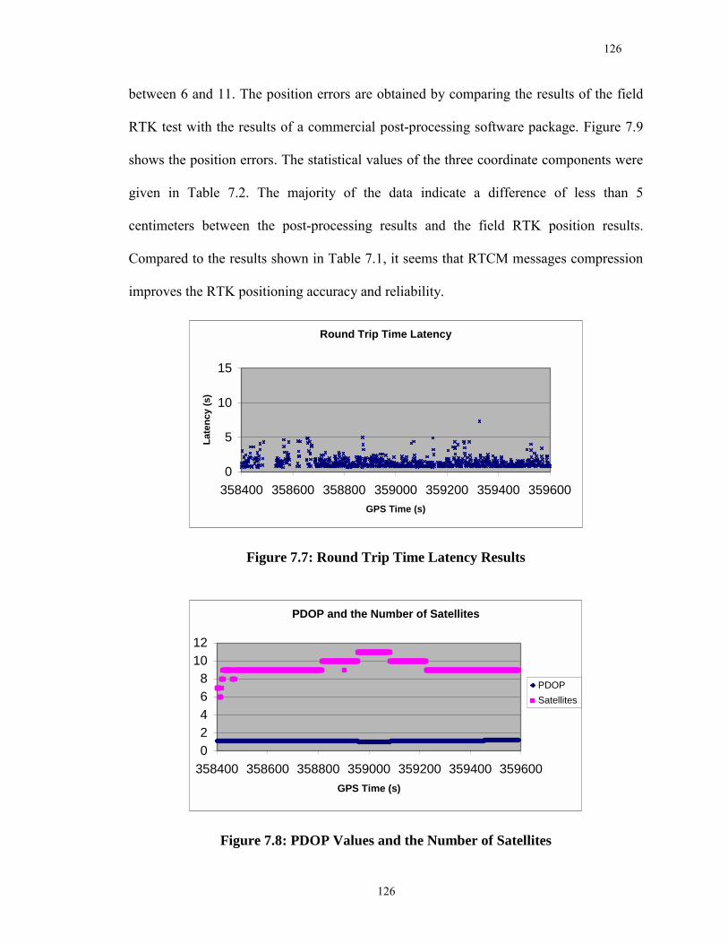
126
126
between 6 and 11. The position errors are obtained by comparing the results of the field
RTK test with the results of a commercial post-processing software package. Figure 7.9
shows the position errors. The statistical values of the three coordinate components were
given in Table 7.2. The majority of the data indicate a difference of less than 5
centimeters between the post-processing results and the field RTK position results.
Compared to the results shown in Table 7.1, it seems that RTCM messages compression
improves the RTK positioning accuracy and reliability.
Round Trip Time Latency
0
5
10
15
358400 358600 358800 359000 359200 359400 359600GPS Time (s)
Late
ncy
(s)
Figure 7.7: Round Trip Time Latency Results
PDOP and the Number of Satellites
02468
1012
358400 358600 358800 359000 359200 359400 359600GPS Time (s)
PDOPSatellites
Figure 7.8: PDOP Values and the Number of Satellites
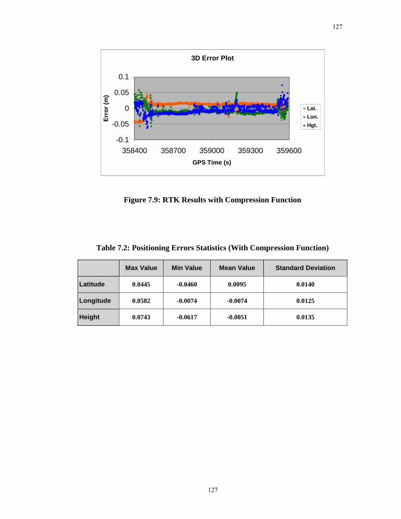
127
127
3D Error Plot
-0.1
-0.05
0
0.05
0.1
358400 358700 359000 359300 359600GPS Time (s)
Erro
r (m
)Lat.Lon.Hgt.
Figure 7.9: RTK Results with Compression Function
Table 7.2: Positioning Errors Statistics (With Compression Function)
Max Value Min Value Mean Value Standard Deviation
Latitude 0.0445 -0.0460 0.0095 0.0140
Longitude 0.0582 -0.0074 -0.0074 0.0125
Height 0.0743 -0.0617 -0.0051 0.0135
128
128
Chapter 8
Conclusions and Recommendations
This research has been focused on the development of an Objected-Oriented (OO)
application framework to promote software reuse in wireless communication software for
Location-Based Services (LBS) applications. Major contributions include the
investigation, design and development of a wireless framework to support the
development of highly reusable wireless communication software system for LBS
applications and the successful application of the developed wireless framework to two
prototype systems, namely, a Real-Time Kinematic (RTK) GPS Positioning System and a
Mobile Equipment Management System.
8.1 Conclusions
The following conclusions can be drawn from the investigations.
1) Object-Oriented framework can be a very efficient and easy-to-use tool for LBS
application developers to support the development of highly reusable wireless
communication software system.
2) A wireless framework has been developed in this research and it has been
successfully used to support the development of highly reusable wireless
129
129
communication software system for LBS applications. In addition to software
reuse, the developed wireless framework can also be used to improve software
maintenance, readability and modifiability.
3) The developed wireless framework supports open structure through the use of
blackbox design and OO technology. Both the wireless framework itself and the
developed applications from it have open structure. Open structure is the key to
incorporate new technologies into existing infrastructures.
4) The developed framework provides an encryption function to support LBS
applications with special requirement on security and a compression function to
support LBS applications requiring high data throughput. The compression
function is able to release the data traffic on the data link and thus improve the
system reliability.
5) The developed framework has been applied to the development of a Mobile
Equipment Management System (MEMS). The field test results show that the
developed wireless framework is able to provide a reliable and safe data transfer
for MEMS applications. The TCP/IP protocol for the wireless Internet and the
Radio/ACK protocol for Wireless radio modems developed from this research can
be applied to ensure no data loss. An encryption function has also been developed
to maintain a high level of data security for wireless communication.
130
130
6) The developed framework has been applied to the development of a wireless
Internet-based Real-Time Kinematic (RTK) GPS positioning system. The field
test results show that the developed wireless framework is able to provide an
adequate data link between the base and rover stations over the Internet. The
round trip time delay is within a range of about two seconds. If the compression
function is used, the traffic on the data link can be reduced and the quality of the
data link is then improved. As a result, the RTK positioning accuracy and
reliability are also improved.
131
131
8.2 Recommendations
Based on the results of this research, the following recommendations regarding the
further development of wireless framework can be made:
1) The user interface of the developed framework should be adjusted according to
the market requirements to make it more user-friendly. A user-friendly user
interface will shorten the learning curve for the application developers to use the
developed framework.
2) Currently there is not a widely accepted standard available to ensure the
commonality for LBS applications. To help ensure commonality of the LBS
interface, interoperability, standards, and testing specification, the developed
wireless framework should refer to the work of the international standards
organizations for LBS such as the Object Management Group (OMG), the Open
GIS Consortium (OGC), the Location Inter-operability Forum (LIF), and etc.
Once there is a widely accepted standard available for LBS applications, the
wireless framework can improve its commonality by incorporating the standard.
3) More LBS applications, which have different requirements on wireless
communication, should be developed based on the developed wireless framework
to further assess its performance.
132
132
4) The developed wireless framework should keep track of the advancements in
technologies and standards related to LBS, since these fast evolving technologies
and standards will determine the future course of LBS applications.
133
133
References
AMCIS (2002), Americas Conference on Information Systems, �Software Reuse and Component-Based Software Development�, Call for Papers for the Mini Track. Dallas, Texas, USA, August 9th - 11th, 2002.
Analysys Inc. (2001), "Mobile Location Services and Technologies Report", Analysys
Inc. Web Site, http://www.analysys.com/ Andreae, P., R. Biddle and E. Tempero (1994), "Understanding code reusability:
Experience with C and C++". New Zealand Journal of Computing, 5(2):23-38, December, 1994.
Arnold, K., J. Gosling and D. Holmes (2000), "The Java Programming Language, Third
Edition", Addison-Wesley Pub Co. Astroth, J. (2001), "Knowledge Sharing and Communication the Hallmark of the New
Economy". GEO INFOMATICS, September, 2001. Autodesk Location Services (2000), White paper 2000. Beck, K. and R. Johnson (1994), �Paatterns Generate Architectures�, European
Conference on Object-Oriented Programming, pp. 139 � 149, Bologna, Italy, July 1994.
Berard, E. V. (2000), "Motivation for an Object-Oriented Approach to Software
Engineering", itmWEB Media Corporation, white paper. http://www.itmweb.com/essay554.htm
Berlin, L. (1990), �When Objects Collide: Experiences with Using Multiple Class
Hierarchies�, Proceedings of OOPSLA 1990, pp. 181 � 193, October, 1990. Printed as SIGPLAN Notices, 25(10).
Bertiger, W.I. and M. Whitehead (1999), �A Prototype Real-Time Wide Area Differential
GPS System�, invited contribution to ION �Red Books�, Global Positioning System: Papers Published in Navigation, Vol. IV, 1999.
Biddle, R., E. Tempero and P. Andreae (1995), "Object-Oriented Programming and
Reusability", Technical Report CS-TR-95/6, Department of Computer Science, Victoria University of Wellington.
Bushmann, F., R. Meunier, H. Rohnert, P. Sommerlad and M. Stal. (1996), �Pattern-
Oriented Software Architectur: A System of Patterns�, Chichester, West Sussex, England: John Wiley & Sons, 1996.
134
134
Cline, M., G. Lomow and M. Girou (1998), "C++ Faqs", Addison-Wesley Pub Co. Codenie W., K. D. Hondt, P. Steyaert and A. Vercammen (1997), �From Custom
Applications to Domain-Specific Frameworks�, Communications of the ACM, pp73, Volume 40, Number 10, October, 1997.
Coplien, J. O. (1996), �Patterns�, New York: SIGS, 1996. DeFusco, D. (2001), " Remote Monitoring Systems: How they can help you save money
". Remote Site and Equipment Management Magazine, June, 2001. Demeyer, S., T. D. Meijler, O. Nierstrasz and P. Steyaert (1997), "Design Guidelines for
'Tailorable' Frameworks", Communications of the ACM, pp60, Volume 40, Number 10, October, 1997.
Deutsch, L. P. (1989), "Design Reuse and Frameworks in the Smalltalk-80 Programming
System", Software Reusability, Volume II, pp.55-71. Reading, MA:ACM Press/Addison Wesley, 1989.
Driver, M. (2001), �Outlook: Java tech trends through 2004 �,
http://www.zdnet.com.au/developer/java/story/0,2000010373,20257033,00.htm, ZDNet US, 27 August 2001.
Ellis, J. R. (1994), "Objectifying Real-Time Systems", SIGS Book, Inc., pp. 4-11,19-22,
29-30, 220-222. Ellipso Homepage (Visited in 2001), http://www.ellipso.com/ Fall Creek Consultants (1998), "The Technologies We Represent...", http://www.comm-
nav.com/tech.htm Fayad, M. and D. C. Schmidt (1997), "Object-Oriented Application Frameworks", the
guest editorial for the Communications of the ACM, Special Issue on Object-Oriented Application Frameworks, Vol. 40, No. 10, October 1997.
Fayad, M. and D. C. Schmidt (1999), "Building Application Frameworks: Object-
Oriented Foundations of Framework Design", pp1,3-5, John Wiley & Sons. Flakstad, N. (2000), �Mine Maintenance Shop�. The PEGG, Vol. 28, No.4, April 2000,
pp16-17. Fowler, M. (1997), "Analysis Patterns: Reusable Object Models", Adison-Wesley,
Reading, Mass., 1997.
135
135
Gamma, E., R. Helm, R. Johnson and J. Vlissides (1995), "Design Patterns: Elements of Reusable Object-Oriented Software", Adison-Wesley, Reading, Mass., 1995.
Gao, Y., Z. Li and J.F. McLellan, (1997). "Carrier Phase Based Regional Area
Differential GPS for Decimeter-Level Positioning and Navigation", ION GPS-97 Part2, P1305-1313.
Gao, Y. and R. Ramsaran (2000), "Mobile Asset Management Toward Operational
Decision-Making", ION GPS 2000, Sept. 19 �22, 2000, Salt Lack City, Utah, U.S.A.
Gao, Y., Z. Liu and Z.Z. Liu (2002), "Internet-Based Real-Time Kinematic Positioning",
Vol.5, No.3, GPS Solutions, Winter 2002. Gibbons, G. (2001), "LBS, Location-Based Services", pp30, GPS World, April, 2001. Goldberg, A. (1984), "Smalltalk-80: The Interactive Programming Environment",
Adison-Wesley, Reading, Mass., 1984. Goraj, S. (1999), JavaTM 2 Complete, SYBEX Inc. Gossain, S. (1990), "Object-Oriented Development and Reuse", Ph.D. thesis, University
of Essex, UK, June 1990. Graham, I. (1991), "Object-oriented methods", Addison-Wesley Publishing Company,
pp.120 -220. GSM World (Visited in 2001), GSM Association Web Site
http://www.GSMworld.com/technology/sms.html GSM World (2002), �Today's GSM Platform�,
http://www.gsmworld.com/technology/gsm.shtml Ha, R. (2001), "GEOIDE Report: Preliminary Survey on Terrestrial Wireless Standards ",
Department of Electrical & Computer Engineering, University of Waterloo, Ontario. January 5th, 2001.
Hada, H., S. Yamaguchi, Y. Kawakita and J. Murai (2000). �Design of Internet Based
Reference Station Network for New Augmentation System�, Proceedings of ION GPS�2000, Salt Lake City, Utah, September 19-22, 2000.
Hueni, H., R. Johnson and R. Engel (1995), �A Framework for Network Protocol
Software�. Proceedings of OOOPSLA 1995, Austin, TX, October 1995. ICO Homepage (Visited in 2001), http://www.ico.com/
136
136
Inmarsat Homepage (Visited in 2001), http://www.inmarsat.org/, Johnson, R. E. and B. Foote (1988), "Designing Reusable Classes". Journal of Object-
Oriented Programming, 1(2):22-- 25, July 1988. Johnson, R. E (1997), "Frameworks = (Components + Patterns)". Communications of the
ACM, 40(10), pp 39-42, October, 1997. JPL (2000), �IGDG (Internet-based Global Differential GPS) �, homepage,
http://gipsy.jpl.nasa.gov/igdg/ Krasner, G. E. and S. T. Pope (1988), "A Cookbook for Using the Model-View-
Controller User Interface Paradigm in Small-talk 80". Journal of Object-Oriented Programming 1(3):26-49, August/September, 1988.
Krueger, C. W. (1992), "Software Reuse". ACM Computing Surveys, 24(2):131-183,
June 1992. LaLonde, W. R. and J. R. Pugh (1991), "Inside Smalltalk Vol. II". Englewood Cliffs,
NJ:Prentice-Hall, 1991. Lee, Y., H. Kim, J. Hong, G. Jee, Y. Lee and C. Park (2000). �Internet Based DGPS for
Mobile Communication User�, Proceedings of ION GPS�2000, Salt Lake City, Utah, September 19-22, 2000.
Lin, Y. B. (2001), "Wireless and Mobile Network Architectures", 2001, John Wiley &
Sons Ltd. Liu, Z., Y. Gao, and Z. Z. Liu (2001), "Development of an Internet-Based Wireless
Platform for Mobile Information Management and Service", ION National Technical Meeting 2001, Jan.22-24, Los Angles, USA.
Location Inter-operability Forum Home Page (Visited in 2001|),
http://www.locationforum.org/, 2001. Lu, X. D. (2000), "Development of Mobile Internet in China", NOKIA Mobile Internet
Conference, 22/23 November 2000. http://www.nokia.com/nmic/lu_xiangdong.pdf?
Luo, N. (2001), Geomatics Engineering, Doctor Thesis, UCGE Reports Number 20147,
The University of Calgary. Magellan Corporation (1998), "GG24 OEM Board & Sensor GPS + GLONASS
Reference Manual�.
137
137
Magellan Corporation (2000), "Ashtech SSRadio Specification", http://www.ashtech.com/Media/PDF/SSRadio_3.99.pdf
McCabe, E. (1999), "Location Based Services Offer a Global Opportunity for New
Revenue", 1999, SignalSoft Corp Web Site, http://www.telecoms-mag.com/issues/199910/tcs/location.html
McLarnon, B. (1997). "VHF/UHF/Microwave Radio Propagation:
A Primer for Digital Experimenters", Proceedings of the 16th ARRL and TAPR Digital Communications Conference (Baltimore MD, October 10-12, 1997)
Meyrowitz, N. (1986), "The Architecture and Construction of an Object-Oriented
Hypermedia System and Application Framework". Proceedings of OOPSLA 1986, pp. 186 � 201, November, 1986. Printed as SIGPLAN Notices, 21(11).
Mitola, J. III (2000), "Software Radio Architecture: Object-Oriented Approaches to
Wireless Systems Engineering", ", John Wiley & Sons, Inc. Mobile Info Web Site (Visited in 2001),
http://www.mobileinfo.com/Wireless_Networks/wireless_wan_bellsouth.htm Mobile Internet Content (2000), "Operators start to follow the scent of location-based
services", Commerce and Applications, Nov.17,2000 Montlick T. (2002), �What is Object-Oriented Software?�,
http://catalog.com/softinfo/objects.html (Visited in May, 2002).
Mowbray, T. J. and R. Zahavi (1994), "The Essential CORBA: System Integration Using
Distributed Objects", John Wiley & Sons, Inc., pp. 77-79. Muellerschoen, R., W. Bertiger and M. Lough (2000). �Results of an Internet-Based
Dual-Frequency Global Differential GPS System�, Proceedings of IAIN World Congress in Association with the U.S. ION 56th Annual Meeting, San Diego, California, June 26-28, 2000.
Muellerschoen, R, Y. E., Bar-Sever, W. I. Bertiger, and D.A. Stowers (2001). �NASA�s
Global DGPS for High-Precision Users�. GPS World, Vol 12. No. 1. Namie, H., N. Tanaka, and A. Yasuda (1999). �RTK-GPS Positioning In Japan By GPS-
Based Control Stations Via DMCA Mobile Radio Communication System�. Proceedings of 1999 National Technical Meeting & 19th biennial guidance test symposium, January 25-27, 1999, San Diego, CA.
138
138
Nguyen, L. (2001). "Mobile Internet: Internet Revolution or Mobile Revolution?", DiamondCluster White Paper, http://www.diamondcluster.com/work/Wpapers/WPWireless.asp
ObjectVenture (2001), white paper, �ObjectVenture�s Wireless Solutions�, http://www.objectventure.com/files/rwf/RWFWhitePaper.pdf, 2001. Open Location Services Initiative Home Page (Visited in 2001), http://www.openls.org/,
2001 Pacific Crest Corporation (1998), �RFM96 Radio Modem User�s Guide�, Revision 5.0,
Pacific Crest Corporation, October 1998. Pacific Crest Corporation (2000), "The Guide to Wireless GPS Data Links", 2000. Peck, J. and M. Murphy (1997), �Mining Enters the Information Age�. Automin 7, 7th
Canadian Symposium on Mining Automation, pp. 17-23. September 17-19, 1997, Fort McMurray, Alberta.
Prasad, M. (2001), "Location Based Services", GIS Development Net Web Site,
http://www.gisdevelopment.net/application/LBS/LBS002.htm Pree, W. (1995), "Designing Patterns for Object-Oriented Software Development".
Reading, MA:ACM Press/Addison Wesley, 1995. Qian, L. (1996), "Building 3D GIS by Object-Orientation", Department of Geomatics
Engineering, UCGE Reports number 20088, University of Calgary. Ramsaran, R., Y. Gao and Z. Liu (2000), "Development of a Mobile Equipment System",
the CIM conference in May 2000. Ramsaran, R. (2000), �Development of a Mobile Equipment Management System�.
M.Eng. thesis, October 2000, UCGE Report No. 20146, The University of Calgary.
Regis, J. and B. Bates (2000), "Bradband Telecommunications Handbook", 2000,
McGraw Hill Companies. Sametinger, J. (1997), �Software Engineering with Reusable Components�, Springer-
Verlag, ISBN 3-540-62695-6, 1997. Schmid, H. A. (1995), "Creating the Architecture of a Manufacturing Framework by
Design Patterns". Proceedings of OOPSLA 1995, pp. 370-384, Austion, TX, July 1995.
139
139
SearchSolaris Definitions (2001), �Java�,
http://searchsolaris.techtarget.com/sDefinition/0,,sid12_gci212415,00.html, Jan. 30,
2001.
SearchSolaris Definitions (2001), �Portability�, http://searchstorage.techtarget.com/sDefinition/0,,sid5_gci212809,00.html, July. 31, 2001.
SearchSolaris Definitions (2001), �Robust�,
http://whatis.techtarget.com/definition/0,,sid9_gci212913,00.html (Visited in Jan., 2001).
Spencer, H. (1988), "How to Steal Code". Proceedings of the Winter 1988 USENIX
Technical Conference, Dallas, TX, 1988. Sun Microsystems (2002), �JavaTM 2 Platform, Micro Edition (J2METM Platform)�,
http://java.sun.com/j2me/ (Visited in Mar. 2002). Sun Microsystems (2002), �Technical Overview of Embedded Java Technology�,
http://java.sun.com/products/embeddedjava/overview.html (Visited in Mar. 2002).
TechTarget.com, Inc., (2000), "object-oriented programming",
http://whatis.techtarget.com/definition/0,289893,sid9_gci212681,00.html TMI Homepage (Visited in 2001), http://www.tmi.ca/solutions/tminet_space.html Trimble Navigation Limited (1996), "RTK License Information Update for Dealers and
Customers in the United States", http: //www.trimble.com/survey/fcc.htm Virginia Tech. (2000), "ECPE6504: Wireless Networks and Mobile Computing", Spring,
2000. Vlissides, J. M. and M. A. Linton (1989), "Unidraw: A Framework for Building domain-
Specific Graphical Editors�. Proceedings of the ACM User Interface Software and Technologies 1989 Conference, pp. 81 � 94, November 1989.
Vlissides, J. M., J. O. Coplien and N. L. Kerth (1996), "Pattern Languages of Program
Design 2". Reading, MA:ACM Press/Addison Wesley, 1996. Webcom Communications Corp. (2001), �Announcing Remote Site & Equipment
Management: A New Magazine for Managers of Remote Sites, Facilities and Equipment�. http://www.infowebcom.com/press4.htm
140
140
Winter, S., E. Pontikakis and M. Raubal (2001), "LBS for Real-Time Navigation". GEO INFOMATICS, May, 2001.
Wirfs-Brock, R. J. and R. E. Johnson (1990), "Surveying Current Research in Object-
Oriented Design". Communications of the ACM 33(9): 104 � 124, 1990. Wong, P. and D. Britland (1995), "Mobile Data Communications Systems", 1995, Artech
House, Inc. Zhodzishsky, M., M. Vorobiev, A. Khvalkov and J. Ashjaee (1998). �Real-Time
Kinematic (RTK) Processing for Dual-frequency GPS/GLONASS�, Proceedings of ION GPS�1998, Nashville, Tennessee, September 15-18, 1998


![FAO September 7 th 2009 Presentation Jean-Louis DUVAL [FAO consultant] Michael LARINDE [FAO AGPS]](https://img.pdfslide.us/doc/110x75/56649f305503460f94c4a48b/fao-september-7-th-2009-presentation-jean-louis-duval-fao-consultant-michael.jpg)