Embed Size (px)
Citation preview

- * - _ - 0 - --;:. 3-
- - _-- '! (UAS.A.-CB-135316) AT'ON PEBflSELECTIVE --a- ---- . : llEC1BFAhE Suamary Report (Ionics, Inc . ) - - :. 77 p HC AOS/IIP A01 CSCL 1 O A
- _.: -
https://ntrs.nasa.gov/search.jsp?R=19780010572 2018-07-09T02:26:07+00:00Z
NASA CR-135316
ANION ERMSZIECTTVE MEAWRANE
Samuel S. Alexander Russell B . Hodgdon
Ionics, Incorporated Research Division
65 Grove S t r t Watertm, Massachu~atts 02172
Prepared for
NATIONAL AERONAVTICS AND SPACE ADMINISTRATION
NASA Lewis Research Center Contract NAS 3-20108
Richard W . Lauver, Project Manager

To: NASA-hwis Research Center
Cleveland, Ohio 44135
Attn: Mr. R. W. Lauver
301-2; KS 49-1
A Summary Report
Anion Fennse lect ive Membrane
NAS 3-20108
Submitted by: Research Division
Ionics , Incorporated
65 Grove Street
Watertown, Massachusetts 02172
T e l : (617) 926-2500
Prepared by: Samuel S. Alexander
Russell B . Hodgdsn
T -I
\ I
- /
Approved : , _ _ , - - L
Edgardo J . Parsi
Director of Research

FORWARD
This document cons t i tu tes t h e f i n a l report for t he work accomplished
between June 1975 and J u l - 1977 by Ionics, Incorporated f o r t h e National
Aeronautics and Space Administratxon, b w i s Research Center, under Contract
NAS-3-20108 e n t i t l e d SYNTEESIS AND CHARACTGRIZATION QF IMPROVED ION
SEfECTIVE SEMIPERMEABLE ANION E X m N Q % -NES.
D r . Russell B. Hodgdon provided overa l l program management. The
princi.pa1 inves t iga tor was Samuel S. Alexander with major contr ibution frm
W. W. :?site, C. H. Swenson, A. Scieszko and R. B. Hodgdon.
Thanks a r e due t o Cindi Krawczyk f o r her patience in typing the
f i n a l repor t manuscript and its many revisions.

1.0 XNTRODUCTION AM, S-
21;h objective of NAS 3-20108 was the dewelopcaent and evaluation of
improved anion select ive membranes useful a s e f f i c i en t separators i n a
redax - w r storage cell system being c c n s L ~ c t e d a t the NASA U w i s
Research Center, Cleveland.
T)rs program was divided in to three parts, (a) optimization of the
selected candidate -ane systems, @) inti ss t iga t ion of a l ternat ive
n smbrane/polymar system, and ic 1 characterizaticaa of candidate membrane#.
Tha majcr synthesis e f f o r t was aimed a t improving and optimizing a s f a r
as possible each candidate system with respect t o three c r i t i c a l membrane
properties essen t ia l for g o d red= cell -performance,
(1) high se lec t iv i ty , minimal t ransfer of the reactive metal cations (Contract t a rge t - 10'~ equivalents ~ e + 3 per Faraday or l ess )
(2 ) l aw e l e c t r i c a l r e s i s t i v i t y (Contract target - 20 ohm-cm or less in l N E Z C l a t 80%)
(3) long term durabi l i ty i n redox environments (Contract t a rge t - a t l e a s t 1000 hours in 2M FeCl3 and 2M CrC13 a t SOOC).
Substantial improvements were ma& in 5 candidate aernbrppe systems,
the 103QZL, A3L, BZLDT, CDlL and CP4L. These were prepared by the bulk
polymerization of l iquid monomers on synthetic fabr ic backing. The
c r i t i c a l synthesis variables of cross-link density, monomer r a t i o , and
solvent caapositiaa were examined over a wide range. A s i x th system was
included i n the candidate group, the A3L-96, in a low porosity configura-
t ion.
In addition, e ight a l ternat ive polymer systems were investigated,
two of which, the C D U and CP4L, attained candidate s ta tus , Three other
a l ternat ives showed potent ia l but required fur ther research and developnent.
These were the VC-TP (aminated EVC fi lm) , CT and CTM systems.
Each candidate system was optimized for se lec t iv i ty . In each case
the optimum monomer formulations were ident i f ied which produced membranes
2

with a minim1 t r a n s f e r r a t e f o r ~ e * ~ . In general , these were formulations
having the minimum solvent content which could y ie ld physically s t a b l e
arambranes. The bes t membranes of the candidate group gave t r a n s f e r s of
- 8 1 0 m g F , a range which approaches the contract t a r g e t
-4 t r a n s f e r r a t e of 10 equivalents p r Faraday. Analogous candidate membranes
which were synthesized i n the previous cont rac t period had yielded t r a n s f e r
r a t e s of 50-1000 x mg Fe/cnF.
The spec i f i c resistivities of t h e optimized candidate r e s i n s w e r e
about 35-65 ohm-cm i n 1 N HC1 a t 80'~. Improvement i n the absolute elec-
t r i c res is tance of the membranes was demonstrated by reducing the f i lm
QD thickness below t h a t of the standard Dynel backed membranes (0.6 mm) . The membrane res is tance was reduced by a f a c t o r of about two t o th ree
by the use of a va r i e ty of l i g h t weight f ab r i c s a s backing material .
These included material i n modacrylic, , polypropylene and glass.
The most successful l i g h t weight f ab r i c was a woven modacrylic yielding
2 the lowest r e s i s t i v i t y (2n-~m ) and excel lent durab i l i ty in the CP4L
membrane system. This f ab r i c , hcrwever, was compatible only in the more
polar monaner systems ( the CP4L and the CDlL) . Other materials shmed
variable r e su l t s . Only t h e membranes on the standard Dynel woven and
the above modacrylic have shown the most consistence and r e l i a b l e physical
in teg r i ty on manfacture; and long term durab i l i ty on t e s t ing . A f i lm
thickness of about .lo--25 mm appears t o be the minimum feas ib le range
f o r viable membrane manufactured by bulk polymerization and fabr i c
saturat ion.
Very low r e s i s t i v i t i e s were measured i n the VC-TP system (aminated
t h i n commercial W C f i lm) but candidate s t a t u s was not recommended because
+3 of excessive Fe permeability and IEC loss a t elevated temperature.
The candidate ranking highest i n overa l l proper t ies and performance

was the CP4L-A2 membrane, a copolymer of 4 vinylpyridine and vinylbenzyl-
chloride. The optimized CP4L-A2 membrane (on woven modacrylic ) w a s a
rugged, extremely durable f i lm 0.23 m in thickness w ~ t h an area resis-
2 + t i v i t y R; = 1.8 ohm- , and permeability, ' ~ e = 4-8 x l ~ - ~ m ~ n/mE'.
The t o t a l IEC w a s about 5 meq/dgr . (50% s t rong base) , t he highest in
t h e candidate group. The s t a b i l i t y of a l l c r i t i c a l membrane proper t ies
was exce l l en t a f t e r 1000 hours i n both Z! F&13 and ZM CrCl) a t 80°c.
(Table 1) . The other candidate membranes ranked b e l w the CP4L system because
of one o r more d e f i c i t s and are l i s t e d S e l ~ w i n t h e descending order of
o v e r a l l des i rab le propert ies .
The A3L-B7 membrane - a c3polymer of 2 vinylpyridine and d iv inyl -
benzene ranked next iii o v e r a l l des i rab le proper t ies . It was success-
2 f u l l y manufactured on a production scale in 5.5 ft area shee t s on Dyne1
woven fabr i c . The menbrane had exce l l en t d u r a b i l i t y i n both e l e c t r o l y t e
0 Soiutions a t 80 C and very low permeability t o ~ e + ~ . Subs tan t i a l improve-
ment i n r e s i n d u r a b i l i t y w a s obtained by t h e use of DVB in place of
ethylene g lycol dimethacrylate, the c ross l i n k e r used in the earlier
syntheses. The r e s i s t i v i t y of the A3L-B7, however, w a s a t t h e high end
of the candidate range. Membrane samples on woven Teflon and o ther l i g h t
weight backings were made on a l a b sca le showing 50% or more impravernent
in area r e s i s t i v i t y , but were var iable with respect t o f i l m i n t e g r i t y .
The 103QZL-B10 m&mbrane - a copolymer of MIB and VBC post aminated
with tr imethylamhe was o-ptimized f o r s e l e c t i v i t y qiving a t r a n s f e r r a t e
of 2 - 3 x l o g 3 mq h/@. The minimal absolute r e s i s t i v i t y was obtained
on Teflon backing which yielded a membrane f i lm 0.27 m i n th ickness
and a corresponding *crease of about 50% res i s t ance . Resin d u r a b i l i t y
was a x c e l l a ~ t i n FeCl a t 80°c bu t n l y fair in C S 1 3 and 80%. showing 3
sme l o s s of s e l e c t i v i t y in the l a t t e r e l e c t r o l y t e . A t p resent , la rge 4

sca le manufacture is feas ib le only on woven Dynel.
The CDlL-A5 and45H membranes a re copolymers of VBC and dimethylamino-
e t h y l methacrylate (DMAEMA). The membranes have a high IEC of 4.5 meq/dgr
C 2 and a low r e s i s t i v i t y , RB,of 2.9 ohm-cm .
- -----. The membrane, 0.11 m in t h i c h e s s , was successfully prepared in
l ab sca le on l i g h t weight modacrylic f a b r i c which represented t h e minimum
f i b gage and r e s i s t i v i t y in t h i s system. Thin membrane d u r a b i l i t y was
u s e l l e n t in FeC13 a t 8 0 ' ~ and i n C r C l j only a t ambient temperature. The
-3 minimum t r a n s f e r r a t e was 4-8 x 10 mg Fe/mF.
The 92LDT-B2 membrane,a copclymer of VBC and DVB post aminated with
diethylenetriamine (DETA) , showed extremely s t a b l e r e s i n proper t ies in
both e l e c t r o l y t e s a t 8 0 ' ~ buy only fair t o poor d u r a b i l i t y f o r t h e mem-
branes on woven Dynel and Teflon respectively. This was a t t r i b u t e d t o
f a b r i c damage of t h e Dynel in manufacture and inadequate r e s i n f i b e r
adhesion f o r the Teflon. The minimum membrane gage obtained w a s 0.27 mm
C on woven Teflon yie ld ing t h e minimal r e s i s t i v i t y f o r this system R =
2 -3 4.1 ohm- . The optimized t r a n s f e r r a t e was 1 - 2 x 10 mg Fe/rnF.
The A3L-96 membrane - a copolymer of 2VP and ethylene glycol dimeth-
ac ry la te (EGDM) had shown good d u r a b i l i t y i n the previous program but
only a t ambient temperature. This membrane system was chosen a s the
s i x t h candidate because of t h e ease of manufacture i n a one s t e p poly-
merization, and po ten t i a l ly low t r a n s f e r r a t e .
The alterr.ativesystemsVC-TP, CT, and CT?¶ were found promising but
requiring more R & D t o c rea te viable films.
The VC-TP membrane system - W C f i lm aminated with tetraethylene-
pentamine (TEPA) - showed promise because of i ts r e l a t i v e l y high poros i ty ,
high conductivity, and physical s t rength a t .050 .20 mm thickness.

The CT polymer system - a copolymer of VBC and TEPA gave an unusually
high I E C i n the region or' 6-7 meq/dgr. Higher cross linking was indicated
fo r the production of a s table film structure.
The CTM polymar system - a copolymer of VBC and N, N, N' , N t ta t ra-
methylethyleriediamins (TNEDA) yielded a high IEC of 4.5 mealdgr which was
over 90% i n strong base capacity. Higher cross linking was a l so indicated
here t o e f f ec t a more s table res in structure.
Characterization of the membranes was not completed, but suf f ic ien t
data were cbtained t o rank candidates in order of t h e i r probable usefulness
in the redox system. The r e s i s t i v i t y of the optimized candidates over a
w i d e range of HC1 and NaCl concentrations was found t o be a good measure
+ of the candidate's re la t ive effectiveness in excluding the cations H and
+ Na , The most effect ive candizate membrane CD1L-AS and CP4L-A2 showed
the l ea s t r e s i s t i v i t y change over the en t i r e concentration ranqe.
+ The t ransfer r a t e , Pt,. was measured fo r four candidate membranes -
a s a function of FeC1 concontration over a range of 0.5 to 4.0 N. The 3
t ransfer r a t e was ccnstant or s l i gh t ly increased in the 0.5 - 2.0 N span
but increased sharply by a fac tor of approximately three f o r the more
selective nembranes a t 4,ON FeC13. The t ransfer r a t e of t h e most porous
membranes of the se r ies , the 103QZL-B2, hcreased by a factor cf 8.
Polarization e f f ec t s were indicated by the extremely low Fe trm-sfer
r a t e s in high porosity membranes on application of high current densit ies.
+ The 103QZL21gS membrane gave a PFe of about 1-4 mg Fe/S a t 15-l20 ma/m
2
2 range and decreased by 5COI t o 9 x lo-) mg Fe/mF a t 480 rna/cm . L o w
porosity selective candidate membranes showed l i t t l e or no variable
t ransfer e f fec t s over the same range.

2.0 -RAM: SYNTHESIS - CANDIDATE SYSTEMS
In Task I1 (NAS 3-20108) f ive candidate membrane/polymer systems
were invest igated with the aim of optimizing the c r i t i c a l membrane
proper t ies of s e l e c t i v i t y , r e s i s t i v i t y , and durabi l i ty . Three candi-
da tes were se lec ted from the previous cont rac t e f f o r t ; systems 103QZL,
A3L, and B2LDT; and two membranes reached candidate s t a t u s out of Task I
of the present cont rac t , systems C D U and CP4L. A s i x t h candidate was
included, the A3L-% membrane i n a lcrw porosi ty configuraticm.
The membranes were prepared using the bulk polymerization method
with monomer sa tura t ion of the f ab r i c backing. A wide range of the
major synthesis var iables were studied and re la t ed t o the physical
qua l i ty , i n t e g r i t y of t h e polymer f i lm and various electrochemical pro-
p e r t i e s of the membrane, The major synthesis var iables were (1) cross-
l i n k densi ty (f ) or molar r a t i o of the co-monomers ( M R ) ; and (2) non- XL
polymer solvent f r ac t ion (fNp).
Each membrane system was op t iml~ed a t a sheet thickness of 0.60 mm
using wcven Dyne1 fabr i c a s the f i lm backing material because of i ts super-
io r re--.in system canpa t ib i l i ty and durabi l i ty . Scale up t o production s i z e
2 film,, 5.5 f t ?;n area per sheet , was judged t o be feas ib le f o r a l l the
candidate systems and w a s demcnstrated far two, the 103QZL-B2 and A3L-B7
membranes. These membranes were manufactured on a production sca le , in
good y ie ld with uniform physical and chemical propert ies .
Improvement i n r e s i s t i v i t y was achieved by reduction of t h e mel..)rane
t!!ickness through the use of l i g h t weight synthet ic f ab r i c backing.
Membranes were produced on a lab sca le i n the 0.12-0.25 mm thickness
range and showed a corresponding, but not l i n e a r decrease i n area
r e s i s t i v i t y . Manufacturing procedures C a r fabr ica t ing acceptable t h i n
membranes on a large sca le were not f u l l y established. Further investiga-
t ion w i l l be needed i n t h i s area. (Table 1) . 7

2.1 THE 103QZL SYSTEM
The lo3QZL candidate membranes a r e .?opolymers of vinylbenzylchloride
(VBC) and divinylbenzene (DVB) post reacted with t r h t h y l a m i n e (TMA) . The polymer network cons i s t s of a vinylbackbone crossl inked by DVB and
contains a pendant s trong base ion exchange group, benzyl t r imethyl-
ammonium chloride (Figure l a ) . The membraaes are prepared in a two s t e p process ( a ) polymerization
of the f i lm and (b) amination t o a f i x the quaternary ammonium chloride
groups
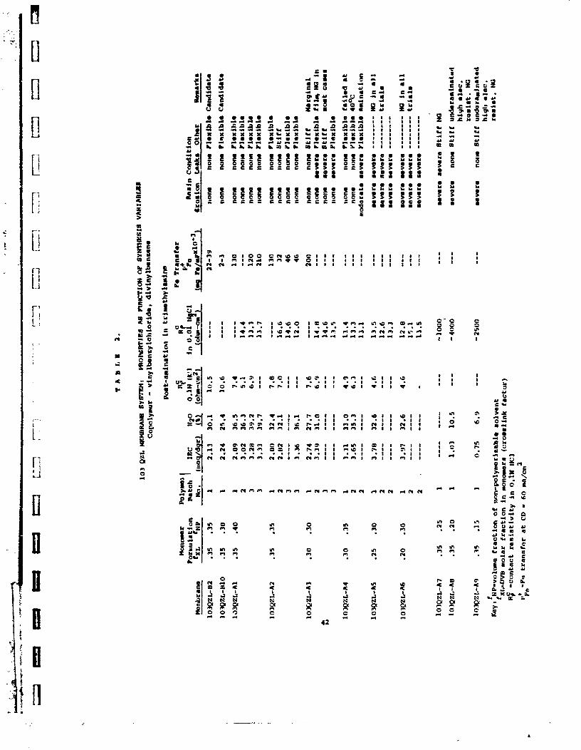
A series of 103QZL type membranes were prepared from d i f f e r e n t form-
u la t ions representing a w i d e range of monomer and non-polymerizable solvent
compositions. The membrane 103QZL-B10 w a s found t o y i e l d t h e maximum
s e l e c t i v i t y i n t h i s series together with good physical and chemical
prop- ies (Table 2) . The optimum m Toner fornula t ion, d e s i p a t e d a s
B10, consisted of a nominal cross l ink densi ty , f 5 . 3 5 , and a non-polymer
solvent content , s.30. The cross l ink a ~ e n t was DV9. %P
The optimized membrane 103QZL-B10 a s manufactured on woven Dynel
backing was a s t rong f l e x i b l e anion se lec t ive membrane sheet 0.60 mm
i n thickness and had the following ,properties:
IEC = 2.24 meq/dgr
H20 content = 25.4% C
Area Res i s t iv i ty , R , i n 0.1N HC1 = 1C.6 A-cm 1
+ ~ e + ~ t r a n s f e r , P = 2 - 3 x 1 0 ~ ~ mg Ene/mP
Fe
The 8-10 membrane on Dynel f a b r i c -Jas proiuced i n good y ie ld i n 1 f t 2
2 sect ions and could be manufactured i n sheets 5.5 f t in area (50 x 100
The Dyne1 backed B10 showed excel lent durab i l i ty i n 2M FeCl a t 80'~. 3
The durab i l i ty in 2M CrC13 w a s expected t o be s imi lar t o t h a t obtained
in the case of 103QTL-B2 nembranes. Loss of s e l e c t i v i t y was measured
a f t e r 100 hrs but remained e s s e n t i a l l y constant from the 200 hr. t o the
l C O O hr . ~ o i n t . 8

Th. B-10 mmbrane was a l so prepared on a lab scale on woven Teflon
fabr ic which reduced the membrane th ickmss t o 0.25 m resu l t ing i n a
C 2 corresponding decrease in area r e s i s t i v i t y , R? = 5.5 A-cm . (Table 1) . The Teflon fabr ic has not yet proven t o be a sa t i s fac tory improvement
m r Dynel due t o the prevalence of pinhole defects in the Teflon backed
mmbranes a s manufactured.
The modacrylic fabr ic was not usable i n the 103QZL system because
of its p a r t i a l so lub i l i ty i n the hot monaner solution. None of the
polypromlene nonowovens produced films of any useful qual i ty .
Further improvement in membrane r e s i s t i v i t y requires creation of
t h i n continuous membrane films on l i gh t weight fabr ics or substra tes
wtdch are both chemically compatible with monomeric consti tuents and
r e s i s t i ve t o the redox environment.
A summary of the experimental monomer formulations tes ted is given
i n Table 2. The major synthesis variables were; (1) crosslink density
(fn) and (2) non-polymr solvent content (f 1 . NP
fxL has been defjned a s the mole f ract ion of the crosslink monomer
based on the t o t a l monaner present.
EvaluatLan Summary - 103 QZL-~10 ~embrane
-B-10 formulation optimum f o r s e l ec t i v i t y . -Large scale manufacture feasible on Dynel woven fabric.
-Membrane on Dynel woven backing is rugged, f l ex ib le and durable in redox environment a t 80°c.
- fmprovement in r e s i s t i v i t y achieved on lab scale by f i l m gage reduction.
-More R & D nee&d on backings and substra tes in order t o improve quali ty.

2 . 2 THE A3L SYSTEM
The A3L membrane/polymer system- is a copolymer of 2 v inyl pykidine
(2VP) and DVB. The membranes are f onned i n a one s t e p Srocess by the
polymerization of the monomers and solvent on f a b r i c by means of heat and
an i n i t i a t o r . The t e r t i a r y cyc l i c amino group is i n t r d u c e d d i r e c t l y
i n t o the polymer s t ruc tu re by the 2 VP monomer and no chemical post t r t a t -
ment is needed t o ac t iva te t h e r e s in . (Figure l b )
A series of A3L membranes were prepared on l ab sca le with varying
proportions of monomers and solvent using w e n Dyne1 f a b r i c a s backing
material . The optimized membrane i n t h i s group was the A3L-B7 membrane
+3 yie ld ing the lowest Fe t r a n s f e r value together with good physica l and
chemical proper t ies . The A3L-B7 polymer was crossl inked with DVB.
The optimum monomer formulation f o r B-7 consisted of a c ross l ink
dens i ty , fXL of .30 and a solvent content , f>lp, of .25. (Table 4 )
The A3L-B7 membrane was manufactured in production s i z e sheets ,
2 5.5 f t i n area a t .60 mm thickness with uniform ~ h y s i c a l and chemical
propert ies . Tlese were:
IEC = 3.2-3.8 meq/dgr
H 2 0 Content = 30.8-33.5%
Area Res i s t iv i ty , R' i n 0.1N HC1 = 4.1-10.3 A-cn 2
?+ -3 Fe Transfer , ' ~ e = 1-2x10 mg Fe/mF
A s pred,cted, MTB monomer imparted super ior chemical s t a b i l i t y
(in W FeC13 and 2M C K 1 3 a t 80'~) t o the A3L membrane/polymer
system i n con t ras t t o the A3L membranes of the previous cont rac t p r i o d
which used ethylene g lycol dimethacrylate (EGDM) a s the c ross l ink agent.
The optimized A3L-07 membrane showed exce l l en t duraS i l i ty i n both FeC13
and CrC13 solu t ions a t BOOC f o r 1000 hr exposure time. (Table 1 2 ) . The
A3L membranes containiag EGDM deterioratsc! progressively under t h e same
conditions.
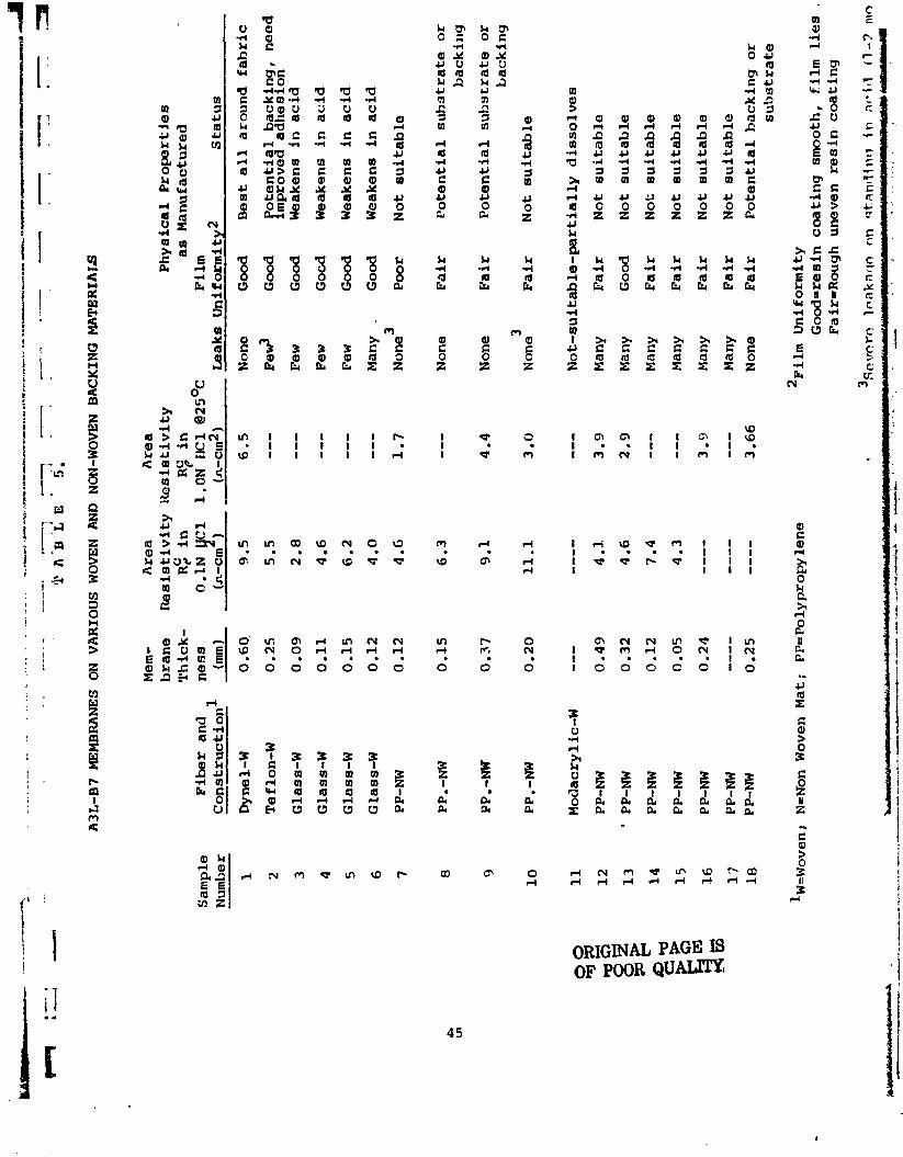
It was demonstrated t h a t the membrane area r e s i s t i v i t y cculd be 10

substantially improved by the use of l ight weight: synthetic backings of
substrates i n place of the standard candidate backing, woven Dynel
(Table 5) . The choice of a backing material is limited by both its corn-
patability with the resin system and its chemical resistance t o the
redox enviroment. A t -is time, woven Dyne1 remains t h e best a l l around
backing material for the A3L system polymers. The fabrics which pro-
duced coberetnt samples an lab scale were uomn Teflon and non-woven
polypropylene. H c m v e r , the quality and durabil i ty on sand* were
varilble and none acheived the overall reliabilit; . of the Dynel .
Evaluation Sununary - A3tB7 Membrane
-B7 formulation optimum for selectivity.
-Large scale manufacture successfully demonstrated on dyne1 woven fabric .
W r a n e is rugged, f lexible arrl has excellent durabil i ty in redox environment a t 80°c.
-Resistivity inprovement by decrease in film/fabric thickness &mastrated on lab scale.
-More R & D needed t o improve film quali ty of th in membranes.

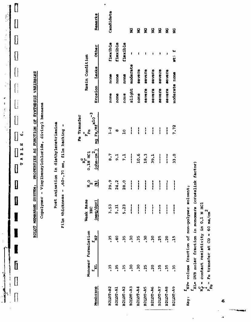
2.3 THE B2IJfi SYSZEM
The B2LDT membrane c a p r i s e s the same bas ic polymer s t ruc tu re as
t he 103QZL bu t is aminated with diethylene triamine (DETA) t o form mainly
primary and secondary amino groups (Figure l c ) . The polymer f i lm is fonned i n the i d e n t i c a l manner a s the 103QZL by
the polymerization of VBC and MIB i n solvent on synthet ic f a b r i c backing
by means of heat and an i n i t i a t o r .
The optimum membrane i n t h i s system w a s t h e B2m-B2 which shoved the
lowest Fe t r a n s f e r value and acceptable physiczl and chemical propert ies
(Table 6 ) .
The base polymer f i lm has been manufactured successful ly ia la rge
2 s i z e sheets 5.5 f t i n area on woven Dynel fabr ic . The B2LDT-B2 polymer
s t ruc tu re and ion exchange groups showed excel lent long range s t a b i l i t y
0 in both FeCl and CrCl so lu t ions a t 80 C. (Table 12)
3 3
Haever , the unsat isfactory durab i l i ty r e s u l t s reparted on t h e
B2LDT-82 membranes were r e l a t ed t o the f a i l u r e of the supporting fabr ic ,
I n the case of the woven Dynel, the f a b r i c was damaged and weakened during
the amination process leading t o fu r the r physical de ter iora t ion of the
f i lm and t r a n s f e r propert ies during the long ranqe durab i l i ty test.
The B2LDT-B2 on woven Teflon sh-d increased ~ e + ~ t r a n s f e r and
eventual c ross leakage i n the 1000 h r durab i l i ty test indica t ing insuf-
f i c i e n t r e s i n f ibex bonding.
Tihe proper t ies of the optimized B2LDT-B2 membrane on Dynel f a b r i c were:
IEC = 3.5 meq/dgr
Water Content = 29.9%
Area Resis t iv i ty . R;, i n 0.19 HC1 - 8.7 A-cm 2
+ -3 Fe t r a n s f e r , PFe = 1-2x10 mg Fe/mF
Improvement i n area res is tance by f i b e r gage reduction was achieved
2 on mmn Teflon (RC = 4.1 A-cm ) . Woven Mdacryl ic proved unsuitable P

because of its solubility i n tha monomer solution.
Thin film B2LDT-B2 membranes require further research and develop-
mant on woven and non-wven support fabrics.
-Selectivity optimized at m e t value or better for Pe transfer.
-Large scale manufacture feasible m wown Dyne~l fabric,
-Polymsr and exchanw groups show excellent stability in redox environment a t 80%-
-Use and treatmemt of support fabric and substrates requires more R & D.

2.4 TEIE CDlL SYSTEM
The CDlL membrane is a copolymer of vinylbenzyl chloride (V9C) and
dimethylaminoethyl methacrylate (DMAEMA) in w h i c h the cross l inks a r e
formed by the condensation reaction of t h e benrylchloride group of VBC
and the t e r t i a r y amino group of DMAEMA. (Pigum Id)
The CDlL membrane can be prepared by e ither a one s t e p or two step
synthesis,
(1) One Step Synthesis - The backing fabr ic is f i r s t saturated with ahaaogenous solut ion or' the monaners and an i n i t i a t o r in solvent. The jernbrane sheet is then formecr between g lass p la tes in a s ingle heating operation by the simultaneous i n s i t u polymerization of the vinyl groups and condensation of the amino and vinyl Senzyl groups t o farm qlnternary amaronium chloride sites.
(2) Two Step Bvnthesis - VBC and DlWNA are f i r s t reacted in H20 t o fonn a w a t e r soluble condensation product, a quaternary ammonium chloride salt of VBC and DMAEMA. I n i t i a t o r is dissolved and the membrane sheet is fonned in a s e c a d heatin? operation by tAhe -wlymeriza- tica of the v w l qoups.
The opthum membrane x l e c t i v i t y in the CDlL system measured by
+3 + minimal Fe t ransfer (PPe) was most closely re la ted, as in other systems,
t o the ~ l v e n t f ract ion (GP) used, The nemSranes CDlL A S , ASE, A6 and
A6H yielded the minimal P+ value and w e r e prepared with the lowest solvent Fe
f ract ion i n t he series tested. (Table 7)
The menbranes C D L - A S and ASH were selected. for candizate status
Secause of t h e i r a g a r a n t lower r e s i s t i v i t y .
The membrane thickness was reduced t o 9-11 tan from the standard of
0.60 am by the successful use of l i g h t weight woven modacrylic. However,
the apparent imprwement was only a 50% decrease or less in area r e s i s t i v i t y
$. This may 5e due t o the more dense yarn construction of the thinner
cloth.
Lab scale samples with good physical qual i ty were -cre-pued on woven
- Aacxylic using the one s tep synthesis. Scale up t o production s i z e -was
not ateenptee.
1 4

The optimized CDlL-AS on modacrylic fabric had the following p ropr t i e s :
IEC = 4.02 meq/dgr (-50% in strong base capacity)
u20 Confent = 30.1% C
Area Resistivity, RI, i n 0.1N HCl = 2.9 n-cm 2
Film Thickness = 0.11 am +
~ e + ~ transfer, PFe = 7-8 .g h / E @
ZDLL-A5 durability in PaCl a t 8 0 " ~ was excellent shaving l i t t l e 3
cc changa in any chemical or physical property of t b film. Homver
the CDlL-A5 resin deteriorated structurally and los t IEC in the more
a~gxessive redox envir-nt, 2M CrCl a t 80°c. A t ambient temperature, 3
CxCI) had l i t t le or no chemical or physical effect on the membrane (CDlL-
ACH fabric) aad on CDlL-A5 on modacrylic fabric. (Table 1 2 )
E ~ a l uation Summary - - CDU-A5 and A5H Membrane
-Optimized for selectivity.
-Film thickness reduced t o 0.11 mm with about 50% improvement i n area resis t ivi ty .
-Excellent durability in FeC13 at 80 '~ and CrC13 a t ambient temp.
-Large scale manufacture feasible using woven Dynel.
-atenti - - for th in film ma.?.?ufacture .

/ I 2.5 THE CP4L SYSTEM . I *
! i The CP4L membrane is a copolymer of 4 vinylpyridine (4VP) and vinyl-
!
benzyl chloride(VBC1. The resin s t ruc tu re consis ts of a vinyl backbone
crosslinked by quaternary ammonium segments formed by the condensation
reaction of the benzyl chlaride part of VBC and t h e pyridine amino group
(Figure la) . The membrane sheet is formed in a one s t e p synthesis s imi la r
t o t h e procedure described in sect ion 2.4,
The CP4L-A2 and A3 membranes have ranked highest of the candidate
grmp in the overa l l s ign i f i can t physical and chemical properties.
(Tables 1 and 8 ) . The system produced the highest IEC, 4.5-5.0 meq/dgr,
the lowest areas r e s i s t i v i t y , R;, 1.8 r a n 2 and a la trans fe r . I n
addit ion, the CP4L-A2 showed excel lent s t r u c t u r a l and exchange group
s t a b i l i t y in both FeC13 aud C K 1 a t 80'~. Lab sca le membranes havt been 3
produced on woven Dyne1 and on woven modacrylic,
The optimized CP4EA2 membrane on modacrylic f a b r i c had t h e follow-
ing propert ies :
IEC = 5.30 meq/dgr (about 55% in s t r m g base capacity)
Water Content = 31.8% C
Area Resis t iv i ty , R p , i n 0.W HC1 = 1.8 A-cm 2
+ ~ e + ~ t rans fe r , P = 4-8x10⁻³ mg Fe/mF'
The superior r e s i s t i v i t y and good s e l e c t i v i t y of the CP4L42 membrane
f : ' : r e l a t e s to the unusually high ion exchange ca-oacity achieved by the 4VP
monaner. The f ixed ion charge densi ty or intersti t ial molality, In, of
the res in was 11.4 mew g H20. The highest IM obtained i n the previous
contract period was 7.5 mq/g H20 ( T e l e 10, NASA CR-134931). The
. . i n t e r s t i t i a l molality is defined as the meq of exchange ca-pacity per
gram of resin water content.
The effect iveness of cat ion exclusion was demonstrated by the small
change obsenred i n CP4L-A2 area r e s i s t i v i t y over the range of 0.1 t o 6.ON
HC1 i n the external solut ion and indicated t h a t the CP4L membrane experiencd
16

+ less H intrusion than the other candidate resins. (Table 1 4 )
Lab scale manufacture of the CP4L was d i r ec t and easy. Urge scale
manufacture of the CP4L appears t o be possible.
Although the modacrylic fabr ic produced excellent membrane films
it w a s chemicaly sensit ive t o the CP4L monomers resul t ing i n some fabr ic
shrinkage and thickening of the end product film t o 0.25 m.
Evaluation S u m a r y CP4bA2 Membrane
-Optimized select ivi ty .
- m o v e d r e s i s t i v i t y by reducing f i l m gage t o 0.25 mn.
-Has highest IEC and lowest area r e s i s t i v i t y of candidate group.
-Excellent durabi l i ty in both FeClj and CrCl a t 80°c. 3
-Viable manufacture on lab scale and potent ia l for large scale pro- duction.

2.6 A3L-97 m N E
Tile A3L-% polymer is composed of 2 vinyl pyridine crosslinkad by
athyleneglycol dimethyacrylate. (Figure I f ) . It w a s selected as the
sixth candidate because of its anticipated ease of manufacture in a one
s e p polymeriratirn process and potentially la ~ e + ~ t ransfer rate. The
i n i t i a l t r i a l using Teflon fabr ic as backing w a s not successful. However,
we expect t o furnish samples of an optimized version on both Dyne1 and a
t h in synthetic fabric.
-Durable membrane in redox environment a t ambient temperat-.
-Potential ease of manufacture in one step polymerization.

3.0 ALTERNATIVE MEMBRANE SYSTEMS
Under Task I (NAS 3-20108) we proposed t o screen a t l e a s t e i g h t
a l t e rna t ive membrane/polymer systems and s e l e c t from t h i s number those
which showed good po ten t i a l for improvement i n s e l e c t i v i t y and e l e c t r i c a l
r e s i s t i v i t y i n addit ion t o ease of manufacture and durab i l i ty i n the redox
environment. The method of f i lm manufacture in most of the above systems
was bulk polymerization of the monaners on synthet ic f ab r i c using heat
and f r e e r ad ica l i n i t i a t o r s . In one system the membrane was formed by
the amination of a commercial WC film. (Table 9)
Wo a l t e rna t ive membrane systems were advanced t o candidate s t a tus .
(1) The CDlL system - a copolymer of vinylbenzylchloride (VBC) and dimethlaminoethy lmethacrylate (DMAEMA)
(2) The CP4L system - a copolymer of VBC and 4 - v i n y l ~ r i d i n e (4VP)
The remaining proposed a l t e r n a t i v e membrane systems were explored
and evaluated. Four systems have shown fi lm manufactur 9 v i a b i l i t y
and promising physical and chemical propert ies . These were:
(1) The CT system - a copolymer of VBC and te t rae thylene pentarnine (=PA)
(2) The CTM system - a copolymer of VBC and N, N, N1, N 1 tetramethyl ethy lane diamine (TMEDA)
(3) The VC1-TP system - PVC f i lm aminated with TEPA.
Three systems were re jec ted because of i n a b i l i t y t o manufacture
f i lms using t h e current bulk polymerization technology. These are :
(1) The CE system - a copolymer of VBC and ethylenediamine GDA)
(2) The CD system - a copolymer ~f VBC and diethylene triamine (DETA)
(3 The CX system - a copolymer of 4VP and Q&' xylenedichloride ( X X )
(4) The SEM system - a copolymer of ethylene glycol dimethacrylate (EDGM) and su l f oethy 1 methacry l a t e (SEMI

THE CT SYSTEM
In this case, vinylbenvyl chloride NBC) is ussd with polyalkyl-
polyamine (TEPA) providing both the needed crosslink segment. (Figure
2a) The CT res in is prepared by a two s tep process in which the active
ingredients VBC and TEPA are reacted t o form an aminovinyl intermediate.
The intermediate is then palymerized by heat and i n i t i a t o r on synthetic
fabr ic . The i n i t i a l membrane samples showed unusually high levels of weak
base IEC i n the range of 6-7 meq/dgr. Hcrwever, the high H20 content of
the membrane and severe res in erosion in acid indicated a weakly cross-
linked polymer structure.
The application of higher cure temperatures and an increase i n VBC
did not suff ic ient ly improve the res in s t a b i l i t y for membranes prepared
by saturation of woven fabrics. However, th in films of the CT res in
bonded t o non-woven substrates showed improved durabil i ty i n acid
solution, an e f f ec t which may be due t o the greater c o n t ~ u o u s physical
support provided by the mat f ibers. The best non-woven backing i n t h i s
regard was a polypropylene mat.
Evaluation Summary - CT System
-Highest IEC attained in program.
-Canponents have high react ivi ty .
-Shows potent ia l f o r th in film manufacture on porous substrate.
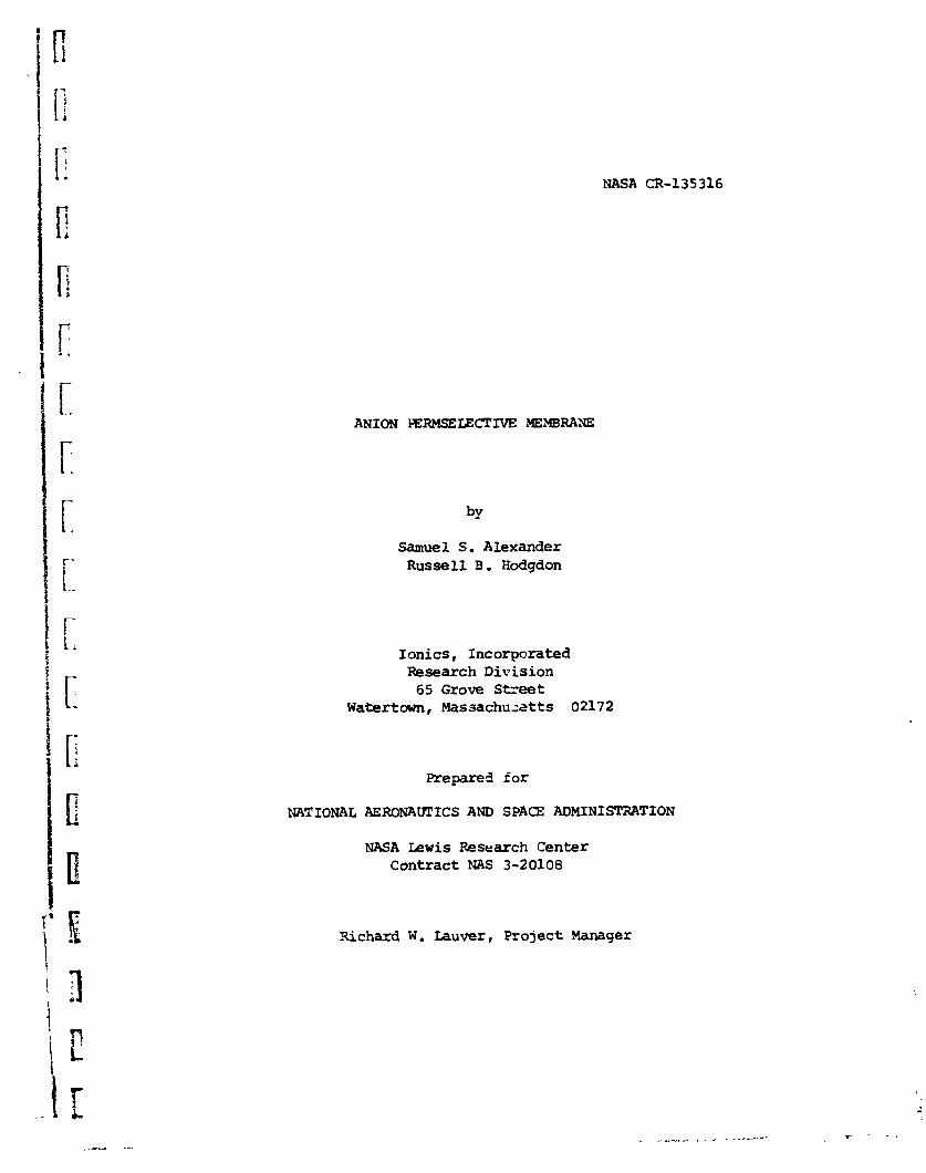
3.2 THE CTM SYSmM
A crosslinked structuce is produced by the condensation of the benzyl-
I rl chloride group of VBC with both ends of the t e r t i a r y diamine, N , N, N', N 1
1 tetramethylethy lens diamine (TMEDA 1 . This f o m s quarternary exchange
1 [I s i t e s a t the cross l ink segment. (Figure 2b)
The CTM membrane was prepared in a one s t e p process. The moncxners
were mixed together i n a solvent containing i n i t i a t o r . Hard, w e l l cured
films were produced when the monomer solu t ion was rapidly polymerized.
Gradual heating tended t o produce undercured films. However, even the w e l l
cured membranes tended t o erode and leak a f t e r severa l days standing i n
ac id environment.
The C'lM polymer system gave IEC values i n t h e 4-5 meq/dgr range
h i c h cons i s t id of over 90% i n strong base capacity.
Evaluation Summary - CTM System
-One s t e p polymerization with very reac t ive monome: >.
-High IEC which is predominantly (90%) strong base capacity.
-Potential f o r t h i n f i lm manufacture.

3.4 THE SEM SYSTEM
The SEt4 membrane/polyrner system iepresenta the sole cation select ive
mnbrane proposed i n the current px,?grm. The SI%M res in is z copolymer of
sulfoethyl methacrylate (SEM) and tha crc.sslinker ethylene glycol dimath-
0 acrylate (EGDM) . (Figure 2g)
The trial samples a s prem-ed on woven Dyael k.ad good integr i ty
2 and area r e s i s t i v i t y in 0.1N HCl, R' = 13.0 ohm-cm . The IEC and
H 0 content was 2.3 meq/dgr and 3e% respectively. 2
(1 !he SEM system, h m v e r , was rejected from further consideration
because of leakage f a i l u r e during tes t ing fo r Fe t ransfer i n 2M FeC1
solution. A l l samples behaved similarly although the or iginal films were
. ! apparently f ree of holes or cracks by inspection and tes t ing with dye. l i Evaluation SUnutIary - S E M
-SEM membrane system not suitable because of res in fa i lu re i n redox solution.

THE VC-TP SYSTEM
The VC-TP membrane system was the sole system prcposed in the current
program which was not produced by bulk polymerization of l i5uid monomers.
The VC-TP membranes were prepared by the amination of t h i n commercial
pcll}~vinylchlori& ( W C ) film using tetraetnylene pantaxnine (TE PA) . The
s t ructure consists of W C chains and pendant polyalkyl polyamiae groups
sane of which may crosslink t!!e EVC chains. The anion exchcnge qroups are
secondary and primary mines. (Figure 2c)
Tables 10 and 11 summarize t h e physical and chemical prcpezti
the experimental '.T-TP membranes produced in the program. A variet.
conmnercial W C films were tes ted canprising film thickness of -025 imn
(1 m i l ) t o 0.20 ma (8 m i l ) and with a p las t ic izer range of 7 t o 30%.
As produced, the membranes tended t o show lw se l ec t iv i ty (excessive
+ 3 Fe transfer). With post treatment of the membranes in FeCl solution
3
and i n a i q t h e se lec t iv i ty was improved but w i t h resul tant loss in IEC
and conductivLty. None of t h e usable film samples prodused in the current
program were recommended for t es t ing a t the NASA Lewis Center because of
the re la t ively high ~ e + ~ t ransfer ra te .
Advantages of the VC-TP membrane -re its film gage (0.025-.20m)
resul t ing in very low r e s i s t i v i t i e s and good film strength and integr i ty .
It tended t o embrit t le somewhat with prolonged heating.
Evaluation S m a r y - VC-TP Membranes - -Membrane as currently produced not sui table for redox application.
-Potential a s conductive thin substrate for application of candidate polymer film.

3.5 THE CE, CD, AND CX SYSTEMS
The following polymer systems were found hworkable f o r d i r e c t and easy
manufacture of useful homocjeneous anion membrane f i lms, These were the:
(1) CE System - copolymer of vinylbenzylchloride (VBC) and ethylene- diamine (Figurn 2d) .
(2) CD Syatem - copolymar of VBC and diethylene triamine (DETA) (Figure .2e) .
(3) CX System - copolymer of 4 vinylpyridine (4VP) and CX, C X 1 d i c h l o r o - v ylene . (Figure 2c)
Successful film manufacture using the bulk polymerization method
required t h a t the monomer-solvent cons t i tuents of the system be miscible
and capable of s t a b l e homoqenous monaner so lu t ions f o r f ab r i c impregnaticm
p r i o r t o polymerization and ~ u r i n g .
The jomponents of t h e a, CD and CX systems were general ly incom-
pat ib le in a wide var ie ty of polar and no~r-polar solvents , separa t i r -
i n t o 2 or 3 phase solu t ions o r producing insoluble p r e c i p i t a t e s dur i r~g
the mixing stage.
xu-
6

4.0 DURABILITY OF CANOIOATE m R A N E S
The anion selective membranes s tudies in t h i s program w e r e caaposites
of a variety of experimental ion-exchange resins and synthetic fabrics.
bmg tenn useful f-mctianing of these membranes as cell separators in a
redo# system requires that the resin st ructure , f i x a:.:r'r,rgo groups, and
the supportive fabr ic have adequate long term s t a b i l i t y and chemical
resistance t o the redarc cell solutions.
The durabi l i ty of the candidate membranes was tested by t h e immer-
sion of 3ledrane samples (3" in diameter) in W FeCl /1N K1 and in 3
W Lxl ./IN )PC1 solutions maintained at 80°c for a period of 1000 hours, 3
A t intervals of lOC,250,500, m d 1000 hours membrane samples were removed
for inspectian and analysis of chemical and physical properties.
Each membrane sample was characterized as follcws:
(a) V i s a 1 inspection for c'--rious gross changes such a s res in erosin surface cracks, color, and f l ex ib i l i t y ,
(b) Nan staining dye test for leak defects
( c ) B u r s t strength or Mullen B u r s t Tester--this data is essent ia l ly a measure sf the fabric dcrabi l i ty as polyelectrolyte membranes .~ve l i t t l e o r r?o s e l f supportive strength
(d) I on exchange capacity (nC)
(e) Water content
( f ) Resis t iv i ty in 0.B HC1
(g) *+3 t ransfer rate
A summary af the durabi l i ty test . resul ts is given in Table 12.
The CWEA2 membrane car woven modacrylic fabr ic ranked highest in a l l
around durabil i ty. .rhe CP4L-A2 s h m d l i t t le or no s ignif icant change in
the essen t ia l functional and structizral membrane properties i n both FeC13
0 d CrCL3 test solations a t 80 C. Sole a l te ra t ion was the resin color
which changed frcm a transparent colorles-; appearance t o a dark opaque
color but with no apparant cStriraent t a 41y measurable chemical o r
physical property.
The A3L-B7 membrane on woven Dyne1 had similar good durabi l i ty

i n a l l functional properties in both redox envirorrments but showed some
film stiffness ar britt leness by 100 hours which produced 3 small loss on
film burst strength (15%) . The lO4ZL and C D U systems exhibited good durability in FW13 but
showed a substantial loss of selectivity aad an increase in water content
i n C; 1 a t 80°c. both effects indicated s- structural deterioration 3
or opening up of the poly~ar net-wzrk, T)re CDlL resin which is crass-
linked by a quaternary a s ~ a d u m chloride shoved a marked decrease in
s t r a g base IEC a& a corresparrding rise in weak base IEC, an effect
caused by spl i t t ing of the carbon-nitrogen exchange groups. The major
&tericuation effects in the 103QZL and CDlL membranes occured in the f i r s t
100 hour period of solution contact and little significant change in
functional properties was measured thereafter fraa the 200 hour t o th
1000 hour mark, The CDlL membranes experienced no embrittleuent of stiffen-
ing and consequently showed no loss in burst strength (fabric strength) in
ei ther solution. A t ambient temperature the CDlL shcrwed excellent dur-
b i l i t y i n the CrC13 test solutiw.
The durability data collected oa the BZLDT-B2 was m h 5. TIME B2LDT-B2
resin exhibited excellent structural and ion exchange group s tabi l i ty
in FeKl and CrC13 a t the elevated temperature, The observed membrane 3
deterioration was due to fabric failure. The l aw burst strength of the
meabrane containing woven Dynel was the resul t of damage t o the backing
durhg the amination step. The B 2 m - B 2 membrane a woven Teflon, showed
progressive increase in transfer leading eventually t o seven leaka-.
The membrane fafiuce in t h i s case was most likely related t o inadequate?
resin bonding t o the Teflon yarn. The most successful and durable candidate
polymer fabric cotpposite films have been an Dynel and modacrylic backing
materials.
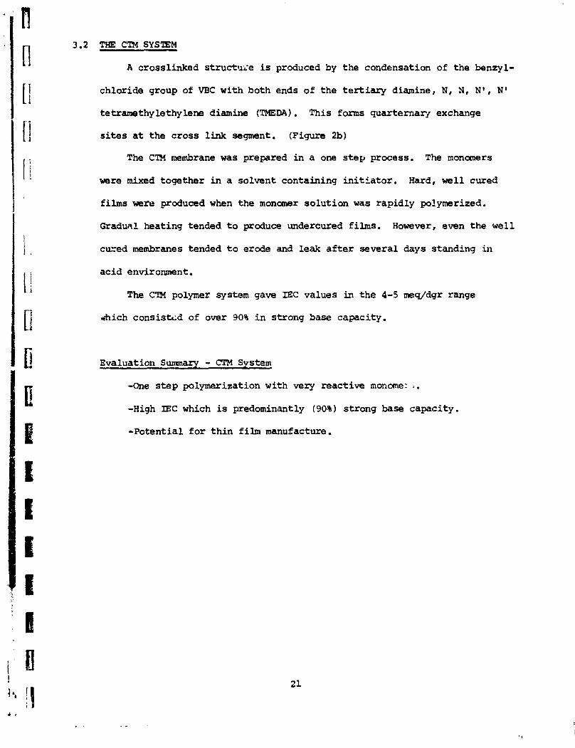
Membrane e l ec t r i ca l resistance is direct ly related t o the thickrress
of the functional resin film. Major improvement or decrease in membrane
resistance can be achieved for a particular optimized candidate polymer
only by a substantial reduction in the resin film thickness.
Haaoqenous ion exdmnge resins are by themselves too f rag i le t o
yield a useful unbmken ctx~tinuous sheet of reasonable size without t h s
aid of a supportive substrate usually a fabric. The candidate membranes
optimized for select ivi ty were manufactured tm woven -1, a fabric
with excellent res in caapat ibi l i ty and chemical durabil i ty but yielding
finished me- sheets 0.55 - 0.65 nun (25 m i l ) in thickness and area
2 r e s i s t i v i t i e s , Itc, in the i-10 ohm- range.
For the purpose of reducing nembrane thickness, about 25 thin gage
woven and non-woven fabrics w e r e screened a s backing material for membranes.
These included modacrylic, Teflon , wlypropy lene and glass.
In t h e bulk polymerizatian methoc? of membrane manufacture the backing
fabric is saturated by the l iquid monomer c-ge whose subsequent -wly-
merization creates a resin-fabric ccanposite sheet. The sheet thinAcness
is Jetermined by the fabric gage. In practice the finished membrane
is usually samewhat thicker than the backing fabr ic due t o swelling and
penetration of the f ibers by the monamers and -solvent. A suitable fabr ic
for membrane support m u s t be chemically compatible, bond w e l l w i t h the
resin and have physical and chemical s t ab i l i t y in the manufacturing process.
fn addition, the support fabric must be thermally and chemically stable
0 in the redcx environment up t o 80 C.
'Re woven and n m woven fabrics considered in the test program
yielded membrane f i h s i n the thickness range of 0.10 t o -50 m. T!E
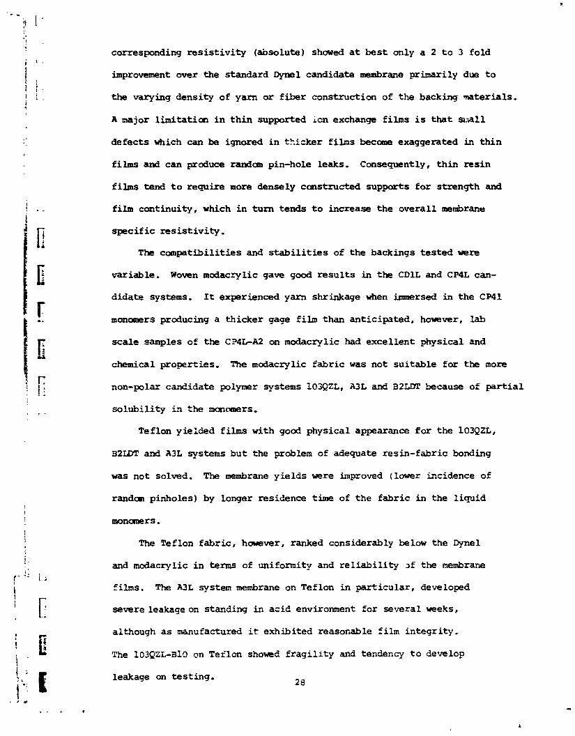
corresponding r e s i s t i v i t y (absolute) showed a t best only a 2 t o 3 fold
improvement over the standard Dyllel candidate membrane prinari ly due t o
the varying density of yarn or f iber construction of the backing mterials,
A major l imitation i n t h in supported ion exchange films i s tha t s:all
defects which can be ignored i n thicker f i l n s become exaggerated in th in
films and can produce randan pin-hole leaks. Consequently, th in res in
films tend t o require more densely cmstructed supports fo r strength and
film continuity, which i n turn tends t o increase the overall meabrane
specif ic res i s t iv i ty .
The compatibil i t ies and st-ilities of the backings tes ted were
variable. Woven modac-~lic gave good resu l t s in the CDlL and CP4L can-
didate systems, It experienced yarn shrinkage when iuunersed i n the CP41
manomers producing a thicker gage film than anticipated, however, la5
scale samples of the CP4L-A2 an modacrylic had excellent physical and
chemical properties. The modacrylic fabr ic w a s not suitable for t h e more
non-polar c d i d a t e polymer systems 103QZL, A3L am5 B2LDT because of pa r t i a l
solubi l i ty i,? the mancuners.
Teflon yie:cied films with good physical appearance for the 103QZL,
32IDT and A3L systems but the problem of adequate resin-fabric bonding
was not solved. The membrane yields were improved (lower incidence of
randan pinholes) by longer residence time of the fabr ic i n the l iquid
mnaners . The Teflon fabr ic , however, ranked considerably below the Dyne1
and modacrylic i n terms of uniformity and r e l i a b i l i t y 2f the membrane
films. The A3L system membrane on Teflon in par t icular , developed
severe leakageon standing in acid environment for several weeks,
although a s manufactured it exhibited reasonable film integr i ty .
The 103Qz~-all) on Teflon showed f r a g i l i t y and tendency t o develop
leakage on test ing. 2 8

Non-wven polypropylene mats shovhd sane promise in the A3L systems,
but behaved very poorly in the 103QZL system.
'RFO special substrate materials, PVC I= sheet and mlt blow poly-
propylene wettable mat indicated good bonding for the A3L system and for
the m o r e polar resh systams such as the CDLL.
Glass rreaves produced film with excallent physical appearance on
manufacture, hauever, glass fibers (E-grade) had very poor durability
in acid, Astroglass, a high temperature resistance grade, and also glass
with protective coathgs or f inish nay be more satisfactory.

6.0 MEMBRANE T(ES1STIVITY I N N a C l AND IiCl SOLUTIONS
The r e s i s t i v i t y of t h e candidate membranes was measured a s a
function of concentration i n I321 an? N a C l so lu t ions a t 25 '~ using the
l iqu id junction method. (NASA CR-134931 APPENDIX 111) The measurements
were taken over a range of 0.1 t o 6.0 N in HC1 and 0.1 t o 5.0 N i n NaC1.
The NaCl so lu t ion was a c i d i i i e d t o 0.01N in HC1 i n order t o maintain
the electrical conductivity of the weak base amino groups. The e lec t ro-
l y t e s we re c i r cu la ted t h e m s t a t e d a t 25 + 0.2Oc. The r e s u l t s are - smmarized i n Tables 13 and 14 and Figures 3,4,5, & 6.
Ion se lec t ive membranes a r e e l e c t r i c a l l y conductive by v i r t u e of
t h e f ixed ionized sites in the r e s i n matrix which permits movement, as
in e l e c t r o l y t e so lu t ions , of the mobile counterion.
Ion exchange r e s i n s a l s o adsorb varying amounts of e l e c t r o l y t e
(Donnan di f fus ion) depending on the physical and chemical proper t ies
of the r e s in , and the nature and composition of the e-xternal e l ec t ro ly te .
The membrane r e s i s t i v i t y as measured in solu t ion represents addit iv6
mobi l i t ies of t h e resin counter ions (~l-) and any adsorbed e l e c t r o l y t e s
(El or NaC1).
E lec t ro ly te exclusion is general ly favored by a high ion exchange
capacity, a high in te rna l f ixed charge densi ty, and law r e s i n porosity.
E lec t ro ly te exclusion is a l s o favored in d i l u t e ccmcentrations, low
valance of the counterions, and high valence of the co-ions i n the
external solut ion. The most se lec t ive membranes are those which a r e
e f fec t ive in excluding e lec t ro ly te a t high cmcentra t ion .
As expected, the membrane r e s i s t i v i t y declined a s the concentration
of AC1 increased producing g rea te r e l e c t r o l y t e d i f fus ion i n t o the res in .
The membrane with the highest porosi ty, the 103QZL-B2 showed t h e g r e a t e s t

drop in res i s t iv i ty . Less resistance change occurred for those nrembranes
having be t te r se lect ivi ty and thus greater effectiveness in excluding
cations. These were the CDlGASH10, AS-3 and the CWL-A2-2 membranes.
One measure of tb aembranes effectiveness in excluding the cation, H+,
was indicated by the r a t i o o f R a t 0.1N HC1 t o R a t 6.ON HCl.
The smallest change in the r a t i o R ( 0 . m (6.0) was shown by the
candidates CDU-AS and CP1L-A2. These membranes have the highest IEC or
ion charge density of the candidate group and should nave high select ivi ty
t o anion t ransfer in strong acid solutions.
The membrane r e s i s t i v i t i e s in NaCl solution (acidified) showed a
smaller decline than in HC1 but were ranked in the same order of ion
exclusion effectiveness. The candidate membranes were be t te r able t o
+ prevent the intrusion of N a because of its lower niobility . The CT4L
membrane showed a higher resistance a t 5,ON NaCl than a t 0.1 N NaCl.
This unexpected hc rease may be due t o an osmotic loss of H 0 £ran the 2
res in a t the high external s a l t concentration.
A t d i lu te e lectrolyte concentration (0.10 N) the membrane r e s l s t i v i t i e s
were approximately the same in e i ther NaCl or HC1 for each particular
candidate. This resistance value represents closely the basic r e s i s t i v i ty 1
of the res in in the ~ 1 - farm as there is minimal contribution t o the resin
conductance by the adsorbed electrolyte. The more selective membranes,
CDlL and CP4L, show a re la t ively f l a t conductivity respmse t o
increased electrolyte concentration indicating tha t very l i t t l e e lectrolyte
is being adsorbed by the resin.
Tables 15 and 16 canpare specific resistance of the candidate membranes
and the e lectrolyte solutions. The CDlL ASH-10 and CP4L-A2 membrane s h w
a specif ic resistance very close t o tha t of 0.10 N NaC1. The data indicates
tha t a s membrane select ivi ty approaches 100% effectiveness, the specif ic
31

res is tance of the membrane ( a t equal IEC values) w i l l tend t o increase
because of the mare e f f i c i e n t exclusion of e l e c t r o l y t e pa r t i cu la r ly the
ac id ic species. Further improvement in membrane s e l e c t i v i t y w i l l tend
t o increase the spec i f i c r e s i s t i v i t y . Thus major reduction i n absolute
membrane res is tance without s e l e c t i v i t y l o s s w i l l require a proportic;-.al
reduction i n mambrane f i lm thickness t o counter balance the increase i n
r e s i s t i v i t y .
The area r e s i s t i v i t i e s of the t h i n film versions in each candidate
system was reduced by a fac to r of 2 t o 3.

7.0 l?eM'l'RAN~FE~ AS A FVNCTIC. OF FtC13 CONCENTRATION
+ The Fe+3 t ransfer rate, PFe, was measured f o r several andi id ate
membranes, the 103QZL-B2 and the CP4L-A2 a t four di f ferent FeC13 concen-
tratians; 0.5, 1.0, 2.0, and 4.0 N acidif ied 1 N i n HCl. m o other
candidates, the 103QZL-B10 and the CDlL-A5H-10 were tes ted a t 0.5
and 2.0 an6 4.0 N.
The w u n t of ~ e + ~ t ransfe r per unit of e l e c t r i c current was a
measure of the membranes functional se lec t iv i ty o r efficiency under
dynamic redax c e l l conditions. The test simulated a redox FeC13 half
cell st a current density CD = 60 ma/cm2, in the charging mode (polari ty)
of cell operation, A detailed description of the test procedure and
apparatus is presented in NASA CR 134931 (page 38, and Appendix IV).
The t ransfer rate, remained approximately constant fo r a l l
membranes i n the e lectrolyte range of 0.5 t o 2.ON, but increased
substantial ly a t the 4.0 N level , The 103QZL-B2, the membrane with the
highest porosity, showed an pet3 t ransfer rate of 127-233 x mg
Fe/mF a t 4,ON FeC13 an e ight fold %crease from a base l i ne of
18-30 x loo3 mg Fe/mP.
The most e f f i c i en t membranes i n the candidate se r ies , the CP4L-A2,
and CD1L-AS shwed only a three fold increase a t 4,ON FeCl 3
A sumnary of the data is given i n Table 17.

8.0 ~ e + ~ TRANSFER AS A FUNCTION GF CURRENT DENISTY
The v a r i a b i l i t y of ~e~~ t r a n s f e r w a s measured as a function of
I 1 : current densi ty f o r three membranes.
(1) the 103cZL-219S, a standard production membrane ( Ionics , Inc.) with a high porosity r e l a t i v e t o the optimized candidate systems
(2) A3L-A5 - low ~ r o s i t y candidate
(3) A3L-A6 - low porosi ty candidate
The var ia t ion i n current densi ty w a s 15 t o 480 ma/cm2 f o r the
lO3QZL-219s and 60 t o 240 ha/cm2 f o r the A3L-A5 and A6. The r e s u l t s ;re
summarized i n Table 18. W e found t h a t the ~ e + ~ t r a n s f e r (or loss ) was
grea t ly diminshed above a CD.120 ma/m2 f o r the m o r e porous membrane,
+ lO3QZL-I3219S. A t CD=480 t h e PFe w a s 7-13 r mg Pe/W a 500 fo ld
reduction from the high Fe loss of about 1-4 mg Fe/mF a t the lower current
densi ty values. (Figure 7)
The more se lec t ive and l e s s porous membranes A3L-AS, A6 showed l i t t l e
o r no changs ,n ~ e + ~ t r a n s f e r with increase i n the current densi ty.
+3 The extreme reduction i n Fe t r a n s f e r observed in the 103QZL-219s
a t high CD values could r e s u l t f r an a polar iza t ian e f f e c t a t t h e membrane
solut ion in ter face . The high e l e c t r i c current demand could produce
+3 depletion of Fe in the i n t e r f a c i a l solut ion film and make it less
avai lable f o r t ransfer . Replenishment of the depleted film by d i f fus ion
+ of e l ec t ro ly tes from the solu t ion bulk would favor the more mobile H
ion which is present i n high concentration.
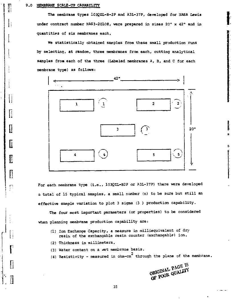
The nembrane t y p s 103QZL-8-2P and A3L-37P, developed for NASA L e w i s
under contrac t number NAS3-20108, were prepared i n s i z e s 20" x 42" and in
q u a n t i t i e s of six membranes each.
We s t a t i s t i c a l l y obtairzed samples from these small production runs
by se lec t ing , a t random, th ree membranes from each, cu t t ing a n a l y t i c a l
samples from each of the three (Labeled membranes A , B, and C f o r each
membrane type) a s follows:
For each membrane type (i.e., 103QZL-B2P o r A3L-372) the re were developed
a t o t a l of 15 t y p i c a l samples, a small number (n) t o be sure but s t i l l an
e f f e c t i v e sample var ia t ion t o p l o t 3 sigma (3 ) production capab i l i ty .
The four most important parameters (or proper t ies) t o be considered
when planning membrane product ion capab i l i ty axe :
(1) Ion Exchanqe Capacity, a measure in mil l iequivalent of dry r e s i n of the exchangable r e s i n counter (exchangable) ion.
(2) Thickness i n mil l imeters .
(3) Water content on a slet medrane bas i s .
(4) Res i s t iv i ty - measured in ohm-en2 through the plane of t h e membrane.

I n the case of the 103QZL-B2P and A3L-B7P membranes, only : 5 samples
each f o r a pa r t i cu la r property have been made avai lable dae t o very
l imited production. These have been 1;ied in Tables 19, 20, and 21.
I n the s t a t i s t i c a l analyses of the small l o t s of the two specia l
membranes, wa can see from Table 22 t h a t our capabi l i ty f o r manufacturing
these new experimental rembranes i n a g o d t i g h t speci f ica t ion range is
good. While t h i s evaluat ion is based upon a very small sampling, it is
unlikely, based on past experience, t h a t the range w i l l increase much more than
a f a c t o r of two when a la rge number of samples of similar material have
been prepared.

0 The CP4L-A2 membrane, a copolymer of 4 vinylpyridine and vinylbenzyl chloride, ranked highest in overa l l propert ies of s e l e c t i v i t y , +3 r e s i s t i v i t y , and durab i l i ty , The optimized proper t ies were; Fe t r ans fe r ratem4-8 mg Fe/mF, Res i s t iv i ty , ~ ~ 1 1 . 8 ohm-cm2 a t 0.23 mrn f i lm thickness, and supsr ior durabi1;ty ifi FeC1 and C r C l ) a t
3
0 The optimized versions of the ~ t h e r candidate membranes were ranked i n the following order; A3L-B7, 103QZL-B10, CDlL-A5, b2LDT-B2. Their optimized ~ e + ~ t rans fe r rat s were in the range of 1-8 mg Fe/mF, and ~,et the contract t a r g e t Feif t r a n s f e r r a t e of -2 mg Fe/mF.
0 The use of t h i n woven and non-woven synthet ic f ab r i c s a s backing materials demonstrated a 2 t o 3 fo ld improvement i n membrane e l e c t r i c a l res is tance by reducing the funct i ma1 film gage t o about . lo t o .30 m range. Several experimental f ab r i c s showed promise a s backings o r subs t ra tes , however, none a t t a ined the excel lent durabi l i ty and use r e l i a b i l i t y of t h e standard heavy gage woven Llynel (f l lm gaget0.6 mm) .
0 The CP4L-A2, A3L-B7 and B2LDT-B2 candidate ~o lymers showed excel lent s t a b i l i t y of resin s t ruc tu re and ion exchange groups i n FeC13 and C r C l a t 80°c. (1000 h r . t e s t )
3
0 The CDlL-A5 a.,d 103QZL-B10 membranes gave good durab i l i ty i n FeC13 a t 80°c and i n C r C l a t ambient temperature.
3
O A t l e a s t three a l t e rna t ive membrane/polymer systems showed promise f o r future developnent because c r f low r e s i s t i v i t y and/or high ion exchanse capaci t ies . These were ?!I, CT, CTM, and VC-TP systems.
2 0 Large sca le manufacturing capabi l i ty (5.5 f t per membrane) was
successfully demonstrated fo r two candidate membrane systems, the A3L-B7 and the 103QZL-B2 on Dyne1 woven backing 183.
0 ~ e + ~ t r ans fe r r a t e s of canhidate membranes were not sens i t ive t o var ia t ions i n FeC13 concentration i n the 0.5 t o 2.0 M range but increased subs tant ia l ly a t 4.OM FeCl 3 '
0 Variations i n current density i n the 60 t o 480 ma/cm2 range did not e f f e c t the ~ 2 ' ~ t r a n s f e r r a t e s i n low porosity and high s e l e c t i v i t y nenbranes. A large decrease i n the t r a n s f e r r a t e was &served in the more porous msmbrme 133QZL-219s above 120 ma/cm2.

11.0 RECOMENDATIONS FOR FURTHER WORK
1. Attempt major reduction ia absolute membrane r e s i s t i v i t y by crea t ion
of t h i n candidate r e s i n fiLv on sul t a b l e backing o r substrate.
2. Invest igate methods of appl ica t ion of t h i n film onto various avai lable
synthet ic subs t ra te materials.
The subs t ra t e s would include - a. non-woven mats i n polypropylene, polyethylene, Teflon,
and carbon;
b. porous o r macro-reticular ion exchange membranes an* films.
3. In tes t iga te a l t e rna t ive polymer systems.
a. heterogenous solvent c a s t films ( ion exchange resin and binder)
b. systen~s with fEC CT-copclymer VBC and TEPA CTM-copolymer VCB and TMEDA with emphasis upon the react ion of VLC with non s t e r i - c a l l y hindered polyamine s .
4. Evaluate above t h i n f i lm and a l t e rna t ive sys5ems f o r - i.ty,
r e s i s t i v i t y , and durabi l i ty .
5. Reduce cat ion t r a n s f e r i n optimized candidate me.nSranes t o v i r t u a l
zero l eve l by crea t ion of high densi ty surface film.

A B S T R A C T
Experimental anion permselective membranes were ia,proved and charac-
terized fo r use as stparators in a chemical redox power storage ce 11
being &-loped at the NASA Lewis Research Center. The goal of m i n h ~ l
ion transfer rpt achieved for each candidate .ambrane system. Minimal
membrane r e s i s t i v i t y -9 demanstrated by reduzticm of film thickness
using synthetic backing materials but usefulness of thin membranes was
l in i ted by the scarcity of compatible fabrics. The m o s t durable and
useful backing fabrics uere mcdacrylics. One membrane, a copolymer of
4 vinylpyridine and viny lbenzylchloride was outstanding in overall
electrockmica1 and physical properties. Long term (10C2 !u) ~lembrane
cheatical and thermal durabil i ty in redax e n v * m t was s h m by three
candidate polymers and two nembranes. The remainder had cood CIurability
a t ambient temperature. Manufacturing capabil i ty was demonstrated for
large scale production of membrane shrets 5.5 f t 2 in area far two candidate
systeas .

Def init ian - Units
pJ Resistivity by liquid junction nethd ohm-cm
4 M resistance by liquid junction ustthod 0hr-o2
f C Resistivity by cmtact p r c h a t h d ob-cm
G Area resistance by contact probe method o h m e 2
+ p~
Srmeaticn factor for Fe in the charging mode lag Ekf-
a9 millifaraday 3
96.5 x 10 Ira-sec
IEC Ion exchange capacity meq,'dry gram resin
I, Interstit ial molality -9 H20

ORIGINAL PAGL 1s OF POOR QUAWTY
- - .-,-* , .--LCsLL*
10
3 Q
LL
WH
RR
AH
B:
8Y
87aH
t Y
RO
WR
TIE
S A
S nM
CI'IU
4
OP
BY
Nn
CS
Ifi
Co
po
lyw
r - v
iny
lben
ry lo
t~lo
rid
., d
ivin
y lb
on
mn
o
mo
t-a
nin
ati
on
In
tri
wst
hy
lun
im
Mon
omer
?o
rmu
lat 1
on
~X
L C
NP
.35
.35
now
non ?
lnx
iblo
Ca
nd
lda
k
no
w
norw
F
leri
blo
n
mo
no
ow
Plo
xlb
la
nano
n
otm
FIo
xlL
L.
na
u
no
w
Plo
xlb
le
I no
no
Clo
xib
le f
ail
ed
at
none
no
rw
Ylo
xlb
l~ 40
%
mod
orat
. o
evo
ro
Ylo
xlb
lo
an
lna
tlu
n
oo
wro
m~
ro
---
-----
NO
in a
ll
mm
m n
ov
ore
---
-----
tria
lm
nw
K0
HV
ore
-----
---
Key
~~
~~
-v
ol
um
e
fra
cti
on
of
~~
on
-po
lym
rlc
ab
lo
oo
lven
t f
~l
.=
~
mo
lar
fra
ctl
on
in
non
-re
(uro
oo
lln
k f
ac
tor)
R;
-co
nta
ct
res
isti
vit
y
in 0.lW
1C
l
P;~
-P*
tra
nsf
er
at
CD
- 60
mn/m
2

Mem
bran
e
, ; I....
-----A
-7 7
- . . - . -,
, .-
- - .
- - - .
-. -
- . --
.
. .
..
....
TA
BL
E
3.
CA
ND
IDA
TE
AN
ION
MEMBRANES
PR
EP
Arn
D
WIT
H D
M
Ba
ck
ing
M
ate
rial -
4 oz
wo
ven
d
yn
e1
clo
th
Fil
m T
hic
kn
ess
- 0
.55
-0.6
5
mm
Cro
ss-
Lin
oa
r Post
lin
ke
r M
onom
er
React i
on
DVU
VBC
e
rnin
nti
on
i
n T
MA
DV
B VUC
am
ina
tio
n
in
TM
A
DV
B
DVB
DVB
2-V
P
1 1 no
ne
MEM
BRA
NE
PROPERTIES
Are
a R
os
ieti
yit
y R
$
Fe T
ran
sfe
r +
P~e
Ph
ys
ica
l C
on
d it
ion
(m
q ~
e/r
ntx
lo-
~)
o
f fi
lm
12
- 4
0
A
Kay :
DM . .
. . .
Dlv
iny
lbe
nz
en
e
@8
V
BC
. ,
. . .
Vin
ylb
en
zy
lch
lori
da
2-V
P
. . .
. .2
-vin
ylp
yri
din
e
TMA . .
. . .
Tri
me
thy
lam
dn
e
2
R$ . .
. . .
Re
sis
tiv
ity
(o
lun-
cm
) b
y
liq
uid
ju
nc
tio
n
in
1.0
M
H
CI at
25
an
d B
OO
C
Ph
ys
ica
l C
on
dit
ion
of
fjlm
- A
=g
oo
d p
hy
sic
al
pro
pe
rtie
s,
lea
k f
ree
, well coated
B=
fnir
p
hy
sic
al
pro
pert
ies,
som
e le
ak
s,
co
nta
ins
cra
ck
o.

TA
BL
E
4.
A3L
MEMBRANE
SYST
EM -
PR
OFE
RT
IES A
S
A
?UN
CT
ION
O
F S
YN
TtiE
SIS
VA
RIA
BL
ES
Co
po
lym
er -
2 v
iny
lp
yri
din
e ,
div
iny
lbe
nz
en
e
Fil
m T
hic
kn
ess
-
.60
-.7
0
mm
, fi
lm b
ac
kin
g-4
oz
Dyne1
clo
th
Fe
Tra
nsfe
r
! I $
+ M
onom
er
Fo
rmu
lati
on
IE
C
H20
0.1N
H
C B
' '~
e
Mer
nbra
ne
'NP
f~
~
(meq
/dg
r)
(ohm
-cm
1
~C
J ~
e/
m~
~l
o-
~
Ero
sio
n L
eak
s O
the
r R
emar
ks
None
Non
e
Non
e Few
Non
e N
one
Non
e Few
Non
e Few
None
None
Non
e N
one
Sli
gh
t Few
Non
e Few
Whole
Cra
ck
s
Whole
Cra
ck
s
Cra
ck
s
Whole
Cra
ck
s
Cra
ck
s
Cra
ck
8
Ca
nd
ida
te
- - - L
ow
Fe
Tra
ns
fer
Low
F
e T
ran
sfe
r,
no
cr-
Low
F
e T
ran
sfe
r
- L
ow
Fe
Tra
nsfe
r
A3
L-A
9
15
.3
0
3.4
9
23.4
8
.9
10
N
one
Few
C
rac
ks
Low F
e T
ran
sfe
r
Key
: f~
~
= v
olu
roe
fra
cti
on
of
no
n-p
oly
mer
so
lve
nt1
f
~~
=~
~~
m
ola
r fr
ac
tio
n i
n m
onom
ere
(cro
ss
lin
k f
ac
tor)
1
q=
co
nta
ct
re
sis
tiv
ity
in
0.1
N
H
Clt
P+
= F
e tr
an
sfe
r a
t C
D=6
O m
a/cm
2 F
e
A3L
-B7
MEM
BR
AN
ES
ON
V
AR
IOU
S W
OVEN
A
ND
N
ON
-WO
VEN
B
AC
KIN
G
MA
TE
RIA
IS
Mem
- A
rea
Are
a b
ran
e
Re
sis
tiv
ity
I
bs
isti
vit
y
Ph
ys
ica
l P
rop
ert
jes
R$
in
R$
in
as
Ma
nu
fac
ture
d
Th
ick
- S
am
ple
F
ibe
r a
nd
n
es
s
0.1N
C
1
1 .O
N
fC1 @
2s0
c
Fil
m
Num
ber -
Co
ns
tru
cti
on
(m
m)
(n-c
m
(A-c
m2 )
Le
ak
s u
nif
orm
ity
2
Sta
tus
Y
1
Dyn
el-W
0
.60
. 9
.5
6.5
N
ona
Goo
d B
es
tall
ar
olr
nd
f
ab
ric
2 T
e f
lon-
W
0.2
5
5.5
--
- ~
ed
I
ote
nti
al
ba
ck
n
g,
ne
ed
t
mp
rov
ed
ad
tle
s o
n
3
Gla
ss-W
0
.09
2
.8
---
Pew
G
ood
we
ak
en
s in
ac
id
4
Gla
ss-W
0
.11
4.
6 --
- F
ew
Go
~d
W
eak
ens
in
ac
id
5
Gla
ss-W
0
.15
6
.2
---
Few
G
ood
Wea
ken
s in
ac
id
6
Gla
ss-W
0
.12
4
.0
---
Man
y .
Goo
d W
eak
ens
in a
cid
7
PP-N
W
0.1
2
4 .G
1
.7
Non
e P
oo
r N
ot
eu
ita
blo
8
PP.-N
W
0.1
5
6.3
--
- N
one
Fa
ir
Po
ten
tia
l su
bstr
ate
o
r
ba
ck
ing
9
PP.-NU
0.3
7
9.1
4
.4
Non
e F
air
P
ote
nti
al
su
bv
tra
te o
r
ba
ck
inq
3
1
0
PP
. -N
W 0
.20
11.1
3
.O
Non
e F
air
N
ot
su
ita
ble
11
Mo
dac
ryli
c-W
--
- --
--
---
No
t-s
uit
ab
le-p
art
iall
y
dis
so
lve
s
12
PP
-NW
13
'
PP-N
W
14
PP
-NW
0.4
9
4.1
3
.9
Man
y F
air
N
ot
su
ita
ble
0.3
2
4.6
2
.9
Man
y G
ood
No
t s
uit
ab
le
0.1
2
7.4
--
- M
any
Fa
ir
No
t s
uit
ab
le
15
PP
-NW
0
.05
4
.3
---
Man
y F
air
N
ot
su
ita
ble
16
P
P-NW
1 '7
PP-N
w
18
PP
-NW
0.2
4
__--
3
-9
Man
y F
air
N
ot
su
ita
ble
----
--
--
---
Man
y F
air
N
ot
su
ita
ble
0.2
5
----
3
.66
N
on
e F
air
P
ote
nti
al
ba
ck
ing
or
su
bs
tra
te
lw=
wo
ven
N
=N
on
Wov
en
Mat
; P
P-
~o
ly
p
rop
y l
en
e
2~
il
m
Un
ifo
rmit
y
Go
od
~r
es
in co
ati
ng
sm
oo
th,
film
li
es
Fai
rmR
ou
gh
u
ne
ve
n
re
sin
co
ati
ng
1i
:1
r1
mu
u~
~1
n~
~-
-~
un
~~
T
AB
LE
6
.
B2LDT HEMBRANE S
YST
EM:
PRO
PER
TIES
AS
FUN
CTI
(X-4
OF
SY
NTH
ESIS
VA
RIA
BIB
S
Cop
olym
er - V
iny
lben
zy lc
hlo
rid
e ,
div
iny
1 b
enze
ne
Po
st a
min
at io
n i
n d
ieth
y le
ne
tria
min
e
Fil
m
thic
kn
ess
- .6
0-.7
0 m
m,
film
bac
kin
g -
- Fe
Tra
nsf
er
Mem
bran
e
Mon
omer
F
orm
ula
tio
n
XL
fN
~
Wea
k Bas8
IEC
(meq
/dgr
1
3.53
5.31
5.23
----
----
----
----
---
- ---
- ---
-
R; +
0.1N
Ii
Cl
p~
e
2 (o
hm-c
m
) m
g F
e/M
f x10-3
Key;
'~
lt vo
lum
e fr
ac
tio
n o
f no
n-po
lym
er
solv
en
t 1
'XI,=
DV
B m
ola
r fr
ac
tio
n i
n m
onom
ers
(cro
ssli
nk
fa
cto
r)
Re
s in
Co
nd
i t ion
Ero
sio
n
Leaks
Oth
er
none
no
ne
none
none
no
tie
none
sli
gh
t m
od
erat
e
none
se
ve
re
sev
ere
se
ver
e
sev
ere
se
ve
re
sev
ere
m
ewre
sever
e se
ve
re
mo
der
ate
none
fle
xib
le
fle
xib
le
f U
xib
le
- - - - - - st]
f
*
Can
did
ate
it>
co
nta
ct
res
isti
vit
y i
n 0
.1
N
HC
1
P+
=
Fe
tra
ns
fer
at
CD
=
60
ma/
cm 2
Fe


I -1 -
u m
m
lu m
ra
m
r-
..
..
-7 - v
fii
iiii
P
53p
i--E---
<
. . - -
. .
: L--
,-4
i
" -3
TABLE
8.
VA
RIA
5IO
NS
I
N C
P PO
LYM
ER
SYST
EM -
PH
YS
ICA
L
&
CH
EMIC
AL
PRO
PER
TIE
S O
F M
EMBR
AN
E
Mon
omer
s -
vin
ylb
en
zy
l c
ho
rid
e,
4-v
iny
lpy
rid
ine
f
~p
=
0.2
5
~a
br
ic
S
up
po
rt -
Dyn
e1
Mem
bran
e s
ize
- 5
" x
5''
Mem
bran
e S
amp
le
CP4
L-A
1
CP4
L-A
2
CP4
L-A
3
CP4
L-A
4
CP4
L-A
5
Vin
yl
Py
r id
ine
M
onom
er
4 V
P
4 V
P
4 V
P
4 V
P
4 V
P
4 V
P
2 V
P
4 VP
4 V
P
Mo
lar
Ra
tio
, M
R V
P/V
BC
IE
C
Imea
/dar
) T
ota
l S
tro
ng
Wea
k %
~
~i
l.
10
.1
(o
hm-c
m
32
2-
Y) H
cl
42
.9
2.4
26
.9
4.2
23
.7
5.8
21
.2
6.5
Jq
.8
5.5
+ F
e T
ran
sfe
r,
PFe
(mg
~e/
*lo
-~)
---
5-9
3-4
2-3
lea
ks
on
tes
tin
g
Ph
ysi
ca
l C
on
dit
ion
of
Fil
m
Su
rf ace
Ero
sio
n
Lea
k
Oth
er
sev
ere
fe
w p
inh
ole
s v
ery
fl
ex
ible
mo
der
ate
few
pin
ho
les
few
cra
ck
s
sli
gh
t fe
w p
inh
ole
s fe
w s
ma
ll c
ra
sli
gh
t fe
w p
inh
ole
s fe
w s
mall cra
sli
gh
t fe
w p
inh
ole
s P
oly
mer
fr
ag
i d
ev
elo
ps
crac
wit
h s
lig
ht
pre
ssu
re
no
ne
few
pin
ho
les
sli
gh
tly
sti
f
no
ne
few
pin
ho
les
mod
. fl
ex
ible
no
ne
no
ne
fle
xib
le
no
ne
no
ne
Dk.
B
r.
Fle
xib
le
'On
~o
da
cr
yli
c Wov
en B
ack
inq
- F
ilm
Th
ick
ne
ss =
.2
5
mm
.


m"
-
-
2
L--!
--
it
=l
cz
a~
n-
1L
,!
~i
1-
7c
a
. -.
TA
BL
E
11
.
MEMBRANE
PR
OP
ER
TIE
S:
AM
INA
TED
PD
I~Y
VIN
YL
CFIW
RIU
d F
IIrM
am
ina
tio
n r
ea
ge
nt
- 1
00
% t
etr
ae
thy
len
e p
en
tam
ine
Fil
m
Th
ick
ne
ss
M
emb
ran
e 1
VC
ITP
-A1
1 0.2
0
VC
ITP
-Bl
, 0
.20
VC
2TP
-A1
/ 0
.05
VC
2TP
-B1
0.0
5
VC
3T P
-A1
0.0
5
Ln
V
C3T
P-B1
0.0
5
I-'
VC
4TP
-A1
0.0
4
VC
4T P
-B1
0.0
4
VC
ST P
-A1
0.0
25
VC
5TP
-B1
. 0.2
5
Pla
sti
ciz
er
C
on
ten
t (0
1
3 0
30
3 0
30
24
24
15
15
7-1
0
7-1
0
Wea
k B
ase
iE
C
maq/dgr
Re
ac
tio
n
Co
nd
itio
ns
A
B
A
E
A
B
A
B
A
B
Ph
ys
ica
l C
on
dit
ion
Fle
xib
le,
Str
on
g
as
ab
ov
e
as
ab
ov
e
as a
bo
ve
as a
bo
ve
as a
bo
ve
as a
bo
ve
as a
bo
ve
Br
ittle
j te
ars
ea
sil
y
Br
ittle
; t
ears
ea
sil
y

IMM
ER
SIO
N
DU
RA
BIL
ITY
T
EST
SU
MM
ARY
-
CA
ND
IDA
TE
AN
ION
MEMBRANES
1'E
ST
E
NV
I RO
WN
T
A=
2ME
eC13
/1N
H
C1
at
80
O~
B
=2M
CrC
13/1
W
IIC
l a
t 8
0°c
C
=2M
CrC
13/1
N
HC
1 a
t a
mb
ien
t te
mp
.
Imm
er-
Ion
Ex
ch
an
ge
Ph
ys
ica
l C
on
dit
ion
of
Mcn
bra
ne
Te
st
s io
n
Ca
pa
cit
y
1120
R
es
isti
vit
y
~e
'~
T
fan
a E
e r
En
vir
on
- T
ime
(meg
/dg
r)
Co
nte
nt
RC
in
O.
l~
~~
l.
p
~ex
10
-3
Bu
rst
Mem
l~ra
ne
En
t
(hrs
) T
ota
l S
tro
ng
Wea
k %
(A
-cm
2 )
(mgk
'e/m
F
) E
rosio
n
Lea
ks
(p
si)
C
olo
r O
the
r
103Q
ZL
-B2
A
0
2-1
3
2.1
3
----
3
0.1
1
0.5
2
2-3
9
None
None
14
5
None
Fle
xib
lc
Dy
ne1
1
00
2
.36
2.3
6
----
3
4.2
9.4
1
5-1
9
NO
~ N
one
12
9
Lt.
B
r.
Fle
xib
le
10
00
2
.26
2
.26
--
--
32 .O
1
1.7
1
0-1
5
None
None
12
4
Br.
S
tif
f
103Q
ZL
-B2
I3
0
2.4
5
2-4
5
----
3
1.4
9
.7
11
-37
N
one
None
13
9
None
Fla
xib
ls
Dyne 1
10
0
2.4
6
2.4
6
----
3€ .l
9.7
3
6-1
00
N
one
None
12
5
Ct.
B
r.
Fle
xib
le
10
00
2
.34
2.3
4
----
3
5.9
1
0.4
5
8-9
7
None
None
12
2
Dk.
B
r.
Stif
f
103Q
ZL
-Dl0
A
C
2
.24
2
.24
--
--
25
.4
i0.6
2-3
N
one
None
14
0
None
Fle
xib
le
Dy
ne1
1
00
2
.59
?.5
9
----
3
0.3
9
.7
3-4
N
one
None
i15
B
r.
Fle
xlb
le
10
00
2
.34
2.3
4
----
2
7.6
1
.4.1
8
-10
N
one
None
12
3
Br.
'
Stif
f
103Q
ZL
-A2
A
0
2.9
8
2.3
8
----
32 .O
6
.5
42
-68
N
one
None
14
0
None
Fle
xib
le
Dyne 1
10
0
3.1
1
3.1
1
----
3
6.3
7
.3
26
-45
N
one
None
13
8
Br.
S1.
Stif
f
10
00
3
.52
3
.52
--
--
38.6
7.4
2
1-5
6
Nan
e N
one
12
1
Pr.
S
1.
Sti
fB
A 3
L-B
7 A
0
3
.~
5 --
--
3.1
9
31.6
9
.1
1-2
N
one
None
14
0
None
Fle
xib
le
Dy
ne1
1
00
3
.31
--
--
3.3
1
29
.8
14
.8
4-7
N
one
None
13
7
Lt.
R
r.
S1
. S
tif
f
10
00
3
.19
--
--
3.1
9
28
.8
12
.2
5 -6
E'
me
None
11
5
Lt.
D
r.
Sl.
S
tif
f
A3L
-B7P
B
0
3
.60
--
--
3.6
0
32
.2
9.5
1
-2
Nor
re
None
14
5
None
Fle
xib
le
Dyn
e 1
10
0
3.5
7
----
3
.57
3
2.4
1
0.8
3-
' N
one
None
13
2
Lt.
B
r.
S1
. S
tif
f
i00
0
3.5
7
----
3
.57
3
1.7
1
1.3
7
-10
N
one
None
12
2
Br.
S
tif
f
A3L
-A5
A n
3
.38
--
3.3
8
27.2
1
0.1
3
-8
N a
ne
N
one
14
6
None
Fle
xib
le
Dyne 1
lG0
3.6
4
----
- 3
.64
3
4.4
7
.8
9-3
7
None
None
14
0
Nol
re
S1
, S
tif
f
10
00
3
.87
--
--
3.8
7
34
.5
9.8
3
2-1
3
None
None
10
9
Dk.
B
r.
S1
. S
tif
f
B2 JDT-B2
A
0
3.5
; --
--
3.5
3
27
.7
8.7
1
-2
Non
e N
C ;r
e 1
00
N
one
Fle
xib
le
Dyne 1
10
0
3.9
3
----
3
.53
3
2.8
1
0.6
1
6-2
5
N o
rle
None
88
Dk.
B
r.
Sti
ff
5
00
3
-60
--
--
C
3.6
8
32
.9
21
.4
46
-57
N
one
Nob
le
87
D
k.
Br.
S
tif
f

f f f 3 2 s X X X 0 9 9 ) r n d d t r a a
0 . 9 . d d d d P P P P 4 - 4 4 X X X X a m . .
1 d d d % a k a
-. - $ 3 2 -! 4 4
f f f t . . 0 bl L( z m m
II J
Q 8 a & ? e l ! 0 o 3 C g t r r g g z ! q s C O o a a a z r ?€d g t ? g g g
0 3 0 z z z z z z z z .iZ z z z e e n : z:8 z z z C a 4 4 =L
a
g r t ~ z t t T Z S e z e a * . 0 0 0 0 0 0 0
a a a t r r 6 8 6 8 $ 8 : ~ ' 2 0 0 0 0 4 4 0 0 0 0 0 0 0 0 : z z z L Z Z Z g 8 Z z z z ZIB z z z z z z Z S Z Z z z z Z Z ~
0 r o c v r @ o m - 0 r o o 0 rn d 0 O In 4 0 0 4cua d n c D Y
9 m . 4 m a w o m - a d - m o d a m o x - 9 4 = a m I I I I Q C Y I I I l l # I - I I l l 1 . 1 1 1 1 0 6 I I l l n o C Y ~ H a m m m m m m o r n d n m o m m - m W N C f - 9 4 0 3 d n a 3 a CY 4 m r( (Y r( 4
4
ORIGINAL PAGE IS OF POOR QUALITY
? ? Y ? ? ? ? ? ? ? ? ? ? ? ? Y ? Y 4 '??? 2 2 3 9 ? ? ? ? ? ? a m 4 a O 6 l m 4 t U l d a m d F P d m O N O N N d m m d ( Y N dU1N ~ n m r , m m W m m m n m n m m m n m m m m m m m m m m n m m m m
m o m ~ m r l m N O O 9 m m n w a ma m a 4 a - 0 * c a m e m @ e a m m a p e m m r o 4 4 - m o m m 1 1 0 m m r l m m m
~. . . . - - - m m m m m m m m o w m m - o o m ~ + P I m w n & + m m m o m m m m
0 0 3 0 0 0 0 0 0 0 C O O 0 0 0 0 0 0 0 0 0 C O O 0 0 0 0 O O C Z 8 d m 0
8 0 O 0 m o = 0 ° - 0
0 0 4 0 O 3 4 0 In O 3 0 ( Y m o * 2 0 0
- 0 C c
d rl rl -I rl rl r( r( rl d


T A B L E 1 3 .
P.IEMBRANE RESISTIVITY AS A FLTCTICX4 OF HC1 CONCENTR4TICeJ
Yethod of *as.- Liquid J u n c t i o n
C e l l Cross S e c t i o n a l Area - 1.36cm 2
>leas. Frequency - 1000 HZ 0
Temp = 25 C
>emt?rane
103QZL-B2
103QZL-El@
l 0 3 ~ 2 ~ - a l 9
A3L-87
A3L-37
A3L-B7
A3L-87
B2LDT-B2
B2LDT-a2
CDlL-A5H-10
CDlL-A, - 3
C?4L-A2
Bi lm T h i c k ~ e s s
~-A)
3.63
3.60
5.27
0.60
G.27
0 1
0.25
0.60
0.27
0.60
0.11
0.23
S o l u t i c n Resis tance (ohms)
t
Sacking Fabric
*el
Dyne1
Tef lon
Dyne1
Tef lon
Polypropylene
Polypropylene
Dyne1 183
Tef lon
Dyne1
Modacrylic
M d a c r y l i c
E.0 1 0 . M . 2
Res i s tance I Fiatio
R0.1fi6.0
6.4
4.7
4.8
4 7
4.6
--- ---
3.4
3.1
2.3
2.4
1.5
+rea R e s i s t i v i t Y 0.1N
13.1
15.4
6.81
15.4
8.50
11 .?$
9.04
12.0
6.53
6.80
3.75
2.39
2.10
R~ , 1B 3 . 5 s
6.eC
3.6
4.24
10.0
5
---- ---- 10.1
5.17
5.75
3.00
2.50
1 . 6 8 1.37
HC: 1
4.17
6.40
2.63
6.45
3.75
3 -17
3-66
7.72
4.13
3.19
2.50
2.15
(,c-m ) 2.09
3.03
4.16
1.55
5.28
2.23
---- ---- 6.43
3.33
3.79
2.15
1.80
6 . 3
2.06
3.26
1.43
3.26
1.35
---- ----
3.54
2.03
2.96
1.58
1 .61

>sthod of Xeasuriii Liquid Jmct ion
C e l l Cross Sectional A r e a = 1 . 3 6 1 ~ 1 2
Xeas. Zrequency - 1 0 ~ 0 .YZ
Temp = 25O:
+ -+sistznco j
-=ti=, XC.1~5I5.0 -,
2.2
1.9
llerrbrane
103~zt-a2
ro3~zt-a~o
A 3L-a 7
a2m-az
CDLL-ASH-10
CDE-As-3
CP4L-A2
i i ,Area .Sesistivitv Thic:kness I xu , 1X YaCl :r-c=l 2 !
m 1 3.1 1 0.5 1 1.0 1 2 - 3 1 5 . ~ .
0.60
0 . 6 3
1.2.3
16.2
0.60
1
5-64
6-61
11.5
4 .
15.9
S o l u t i o n 3es istance 9.92 (ohns
13.4
9.28
12.3
2 .6E
8.37
0.60
0.60
0.11
0.23
7.39
10.5
10.6
1.8
9.36
5.90
3.60
3.17
5.41
12.5
1.4
1.05
1.09
0.63
3 . E 4
13.3
10.2
6.26
3.44
2.77
9.06
5.59
3.34
2.60
11.3
6.2~
3.57
2.18
11.2
6.66
3.64
2.58

T A B L E 15.
SFECIFIC RESISTANCE OF CANDIDATE MWBFlANE IN El
Membrrvre (Electrolyte )
Specif ic Resist ivityf a t 25O~ (A-cm) a t Electrolyte Concentrat ion
0 2 - 0.SN - 1 .ON - 2 .ON - 6 .ON
Measurement by l iquid junction method a t 2s0c
HC1 Conductivity Data - International Crit ical Tables Vol. VI, 1929

T A B L E 1 6 .
S WCIFIC RESISTANCE 3F CANDIDATE MENBRANES TN K s C 1
Spec i f i c ~ e s i s t i v i t ~ ,? a t 2 5 ' ~ (n-cm) Membrane a t E l ec t ro ly t e Concen t r a t im
!Elec t ro ly te ) 0.1N - 0.5N - 1 .ON - 2.ON - 5 .C)N -
NaCl so lu t ions a c i d i f i e d t o 0.01N i n BC1 t o a c t i v a t e weak base amines .
0 Measurement by l i q u i d Jcnc t ion method a t 25 C.
13aCl Conductivity Data - Robinson R. A. and Stokes RII, E l e c t r o l y t e Solu t ions , 2nd ed, 1959 p.466
-and In t e rna t iona l C r i t i c a l Tables, Vol. VI-1929

All FeCl S o l u t i c n s 1.0K in .YCl 3
C*=rent Censity - 6Oma/m 2
r
Yenbrme
lO3QZL-a2
1 03QZL-310
CDLL ASH-10
CP4L-A2-2
I
F i l s I - -3 ?e Transfer ?_ ;zqFe/?nr' x 10 ) 1
3i c..ze s s : e I 4 . 3 9 B e C 1 , ' -
127-233
24-60
12
11-20
13
1
(m) 113 .51PeC1 , -
1
0.60
0 .EL1
0.60
0 . 2 3
0.11
1 2 1 C -
18-30
3-4
3
3-4
-
18-29
-
-
6-3
-
' 17-29
7-15
5-8
4-8
5-2

T A B L E 1 8 .
T e s t E l e c t r o l y t e - 2M F'e C13/lNHCl Temp. Ambient - E l e c t r o l y t e Flow = 1.5cm/sec
Current Density ~ e + ~ Transfer. P+ (mg~e/u@~-~) far Membr-r ~e '
(ma/-2 ) 103QZL-21% A3L-AS A3L-A6
1 5 4 . 1 - 5 . 3 ~ l O 3 -- -

TA
BL
E 19.
SUM
MA
RY
PR
OPE
RT
IES
OF
PR
OD
UC
TIO
N SCALE
CA
ND
IDA
TE
. MEMBRANES
5iz
e o
f in
div
idu
al
sh
ee
t - 2
0V
x42"
(5.8
f
t2)
Back
ing
- D
yne1
No.
sa
mp
les
an
aly
ze
d =
15
C
Ele
c.
Re
sis
. R
e B
urs
t S
he
ets
T
ota
l are
a
IEC
in
o.l
N
HC
1 T
hic
kn
ess
Str
en
gth
M
embra
ne
Man
ufa
ctu
red
Prod.
(rn
eq/d
gr
) !.!E
(o
hm-c
m2
1 (m
) (p
a i
1 P
hy
sic
al
Co
nd
itio
n
103Q
ZL
-B2
6
34
f
t2
2.3
-2.6
3
1 .l
-31
.6
7.9
-9.7
0
.58
-0.6
0
12
9-1
50
N
o leaks, w
ell
co
ate
d, unifor.
2 (3
.16
m
60
f
t 2
3.4
-3.8
3
0.8
-33
.5
9.1
-10
.3
0.5
3-0
.59
1
36
-15
4
3
pin
ho
les,
we
ll c
oa
ted
, u
nif
2
(5
.57
m
1

T A B L E 2c' .
PROPERTIES - SAl4-S FRW PRODUCTION S C A B MEMBRANE
No. Manufactured - 6
Size of Membrane Sheet - 20" x 42"
103QZL-B2P MEMBRANE
LI abrane Sample Burst
psi Thickness
(m) 0..01 NaCl

T A B L E
PROWEYPIES - W m S E'RCM HZCDUCTION SCALE MPIBRANES
No. Manufactured -10
Size ,f Membrane Sheet 2OU x 42"
Burst Thickness ltC 0.1MECL ZEC tprl) (mu) n-cm2 !!!qGE Mmbranc Sample

TA
BL
E
22
.
ST
AT
IST
ICA
L
AN
AL
YS
IS
- ST
AN
DA
RD
A
ND
C
PN
DID
AT
E MEMBRANES
ION h
XC
11A
NG
E C
AP
AC
ITY
b
SW
RA
NE
IE
C
(meq
/dg
r)
WA
TER
C
ON
TE
NT
ti20
($1
FIW
THICKNESS (nun)
RESISTIVITY
(A-c
nr2
)
- 9
9.7
%
- 3
9.7
%
-
99
.7%
-
99
.7%
i x
+3
n
2%
- R
ange
-
- x
+3
d
+%
Ran
ge
x - +3
6
+$
Ran
ge
X
- +3d
2%
R
ange
103Q
ZI,
-B2
P
2.4
6
.23
9
.3
2.2
3-2
.69
3
1.3
0
.6
1.9
3
0.7
-31
.9
0.5
9
.03
4
5.8
-5
6-.
62
8
.7?
..3
1
3.8
7
.5-9
.
- Key:
X =
Av
era
ge
of
sam
ple
s a
na
lyz
ed
+3d= 3
sig
ma
v
ar
ian
ce
-
+%
= V
ari
an
ce
pe
rc
en
t,
3d
-
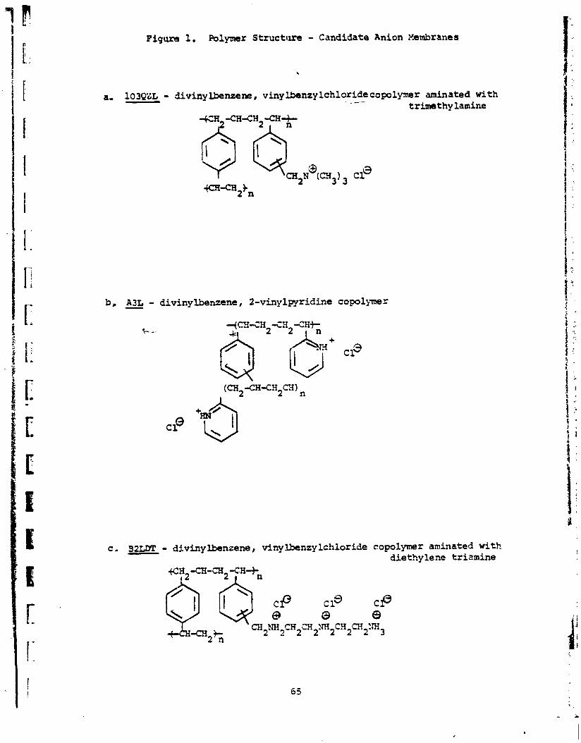
Figure 1. Polymer Structure - Candidate Anion Hembranas
a, 103QZL - - divinylbenzene, vinylbenzylchloridecopolymr . _-. aminated with trimethy lamine
b, L L - divinylbenzene, 2-vinylpyridine copolymer
- divinylbenzene, vinylbenzylchloride copolymer aminated with diethylene trizmine
G H -CH-CE12'C.H+, 12 I

Figure 1. Polymer S t ruc tu re - Candidate Anion Membranes (Cont .)
C D I L - viny lbenzy l ch lo r ide , - CH, >
f CH- CH - CH2 .- CZ .In
0 ' = O CH2 2 CH:
dimethylaminoethylmethyacrylate
c l ! FH3
-Quaternary S i t e N - CH3 I
CH?
CH2 !
0 C=o
T e r t i a r y S i t e I W H - CIIPn
e. CP4L - VBC and 2 o r 4 v iny l pyridine copolymer -
copolymer
A3L-96 - 2-vinylpyridine and e thy lene glycoldirnethacrylate copolymer f r --
CH 3
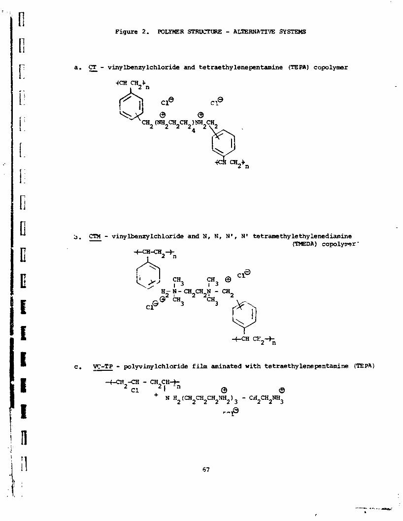
Figure 2. POLYXER STRZICTW - ALTERNATIVE SYSTEMS
a. CT - - viny lbenzy lchloride and tetraethy lenepentamine (TE PA 1 copolymer
CTX - vinylbenzylchloride and N , N , N' , N' tetramethylethylenediamine b. - (TMEDA) c o p o l y ~ r '
f9"2+*
YH3 CFI I 3
N - C R CB N - bi 2 2 *
3 CH3
K - T P - polyvinylchloride film aminated with tetraethylenepentamine (TEP.3) C 9 -

Figure 2 . (Cont .) POLYMER STRljCTURE - ALTERNATIVE SYSTEMS
d . CE - - viny lbenzy lchloride-ett.ylenediamine (EDA copolymer
e . CD - - vinylbenzyl chloride and diethylenetriamine (DETA) copolymer
fCH-CH2+h2 I
f. CX - 4-vinyl pyridine (4-VP) and a am dichloro pxy lene copolymer -

Figure 2. (cont .) POLYmR SPRlXlTURE - ALTEIINATIVE SYSTEMS
g. S z - sulfoethylmethacrylate and ethyleneglycoldimethyacrylate copolymer

- --- ! F I G U R E 3, ----I-
Fi lm Gage-0.6Cllrrm
Film Gage-O.6Omm
Film Gage-0.27mn
1 T 3
Membrane R s s i s t i v i t y , Rc, as a function of H C l Concentration a t 2 5 ' ~ I
103QZL-B2 Membrane
-Dyne1 Backing i !
la3QZL-BlO I 0 - D y n e 1 backing I i A - Teflon backing
i i
i !
i L
! i i i
i i
I I Q
- I I ! I I
D L
i 1
i ! I 1 1 1 i I I i 0.1 0.5 1 .0 2 . O 3 . O 4 . O 5 . O 6.0
HC1 Concentration (N)
ORImAL PAGE IS OF PooR QUIIlTpl

b
r
F I G U R E 4.
I J 0
I Membrane Res i s t iv i ty , R?, as a Function of hCL Concentration at 25 C
i ! A3L-B7 Nembrane
C Dyne1 Backing Film Gage-0.60mm
A Teflon Backint Film Gage-O.27mm
/7 Polypropylene Backing - Fi lm Gage-O.25mm
HC1 Concentration rN)

I 1- F I G U R E 5.
HC1 Concentration (N)

J Membrane Resis t iv i ty , R , a s a Function of HC1 Concentration a t 2 5 ' ~ I
i CDU-A5 Membrane I
0 Dyne1 Backing Film Gage-O.6Omm I I
A Modacrylic Backing Film Gage-O.llmm i
ORIGINAL PAGE IS POQR QU-
I- \ CP4L-A2
j A Modacrylic Backing
! i ! i ! \o t
: \ i
A
: \ n
\ r \ I
O O O
i I
I
i -
HC1 Concentration (N)

3 CLXFtEbiT DENSITY (ma,'cm")
I ! + ? t g u e 7 Fe Transfer ( 2 ! in Anion Selective Membranes a s a Function of Current Density
Fe Membranes: 0 103QZL-21%; fl ' A3L-AS, A3L-A6 Test soln. 2M .1eCl3/1Y E l , C e l l ! po lar i ty - charge m&e Test soln. Flav = 1 . 5 cml'sec.