Embed Size (px)
Citation preview

1 / 8
UAS 582 20110032
Universal Wideband feed system 10,70-12,75 GHz
About this GuideThis document is part of the product.
Read these instructions for use before the initial use of the antenna set.
Perform all operating steps described in the manuals in the specified sequence.
For the most up-to-date version of this document, go to www.kathrein.com.
Keep these instructions for future reference. Pass them on to any new owners when selling or transferring the unit.
Features Universal Wideband feed system with 2 outputs Suitable for Kathrein offset parabolic antennas, type CAS.. (60, 80, 90, 120 cm Ø) For reception of satellites in the Ku band, such as ASTRA, EUTELSAT and TürkSat 50% less cable material required: To receive one satellite, only two cables from the LNB to the wideband multiswitch
are required, with Multifeed, two satellites can be received with just four cables Energy saving - only max. 1,2 W power consumption The feed system complies with ASTRA specifications for universal Wideband feed systems Power supply via coax cable Multifeed-suitable due to compact design Full protection of LNB and cable connections in a ventilated housing, protection category IP 54
UAS 582 2 x F-type plug Allen wrench Azimut-/elevations table Instructions for use
Transport and Storage Transport and store the device in its original packaging. Make sure there is no water condensation build-up.
Intended Use The device described is designed solely for the installation of satellite receiver systems and may only be installed by trained specialist personnel.
The UAS 582 feed system may only be mounted to the listed Kathrein parabolic antennas. If it is used in any other way or if the provisions of this document are disregarded, the guarantee and warranty will become void.
The manufacturer is not liable for accidents caused by the user on the opened device. Unauthorized opening and repair attempts lead to the loss of the warranty claim.
Scope of Delivery

2 / 8
Safety Instructions
The UAS 582 feed system may only be mounted to the listed Kathrein parabolic antennas. The feed system is subject to the same safety and danger warnings as listed in the instructions for using offset parabolic antennas. Please follow these instructions at all times, as otherwise you or other people may be exposed to danger (electric shock through overhead lines, risk of falling down, falling parts, thunderstorm etc.).
Mounting and Connection of the feed systemFixing the feed system (Fig. 1)1. Position the feed system as desired on the multifeed
plate at the end of the bracket (see antenna instruc-tions)
2. Fasten the feed system on the front part using the Allen wrench (torque: 4.5 Nm).
All fastening and tightening can be effected with the supplied Allen wrench (SW4).
Hier ansetzen
MA = 4,5 Nm
Setting the polarisation (Fig. 2)See the value in the table Tab. 1, S. 5 for the polarisa-tion setting.If the value differs from the pre-set 0°, proceed as follows: 1. Loosen both Allen screws (S).2. Turn the feed system to set the reference mark to the
value given in the polarisation pre-setting table.3. Tighten the Allen screws (S) evenly, alternating
between both. Torque: max. 4.5 Nm
Polarisation 0°
Polarisation +15°
Polarisation -15°
Allen screw (S)
Fig. 1: Fixing the feed system
Fig. 2: Setting the polarisation
3 / 8
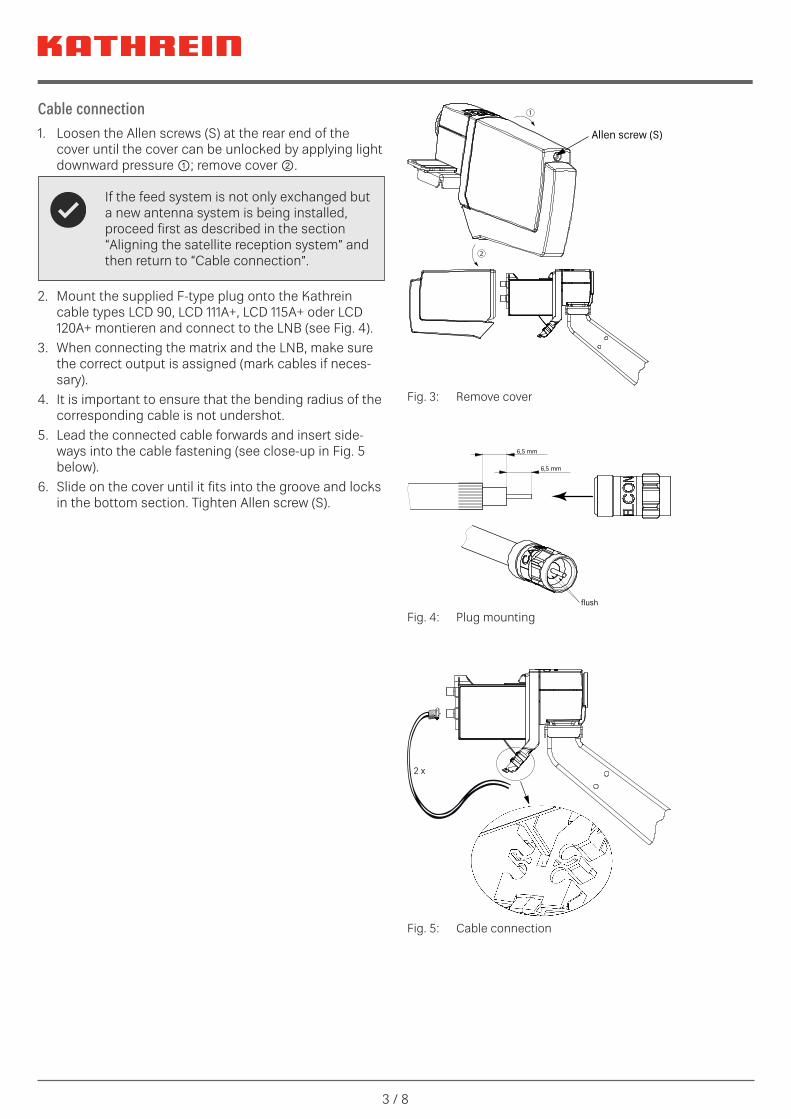
Cable connection1. Loosen the Allen screws (S) at the rear end of the
cover until the cover can be unlocked by applying light downward pressure ①; remove cover ②.
If the feed system is not only exchanged but a new antenna system is being installed, proceed first as described in the section “Aligning the satellite reception system” and then return to “Cable connection”.
2. Mount the supplied F-type plug onto the Kathrein cable types LCD 90, LCD 111A+, LCD 115A+ oder LCD 120A+ montieren and connect to the LNB (see Fig. 4).
3. When connecting the matrix and the LNB, make sure the correct output is assigned (mark cables if neces-sary).
4. It is important to ensure that the bending radius of the corresponding cable is not undershot.
5. Lead the connected cable forwards and insert side-ways into the cable fastening (see close-up in Fig. 5 below).
6. Slide on the cover until it fits into the groove and locks in the bottom section. Tighten Allen screw (S).
Allen screw (S)
①
②
Fig. 3: Remove cover
6,5 mm
6,5 mm
flush
Fig. 4: Plug mounting
2 x
Fig. 5: Cable connection
4 / 8
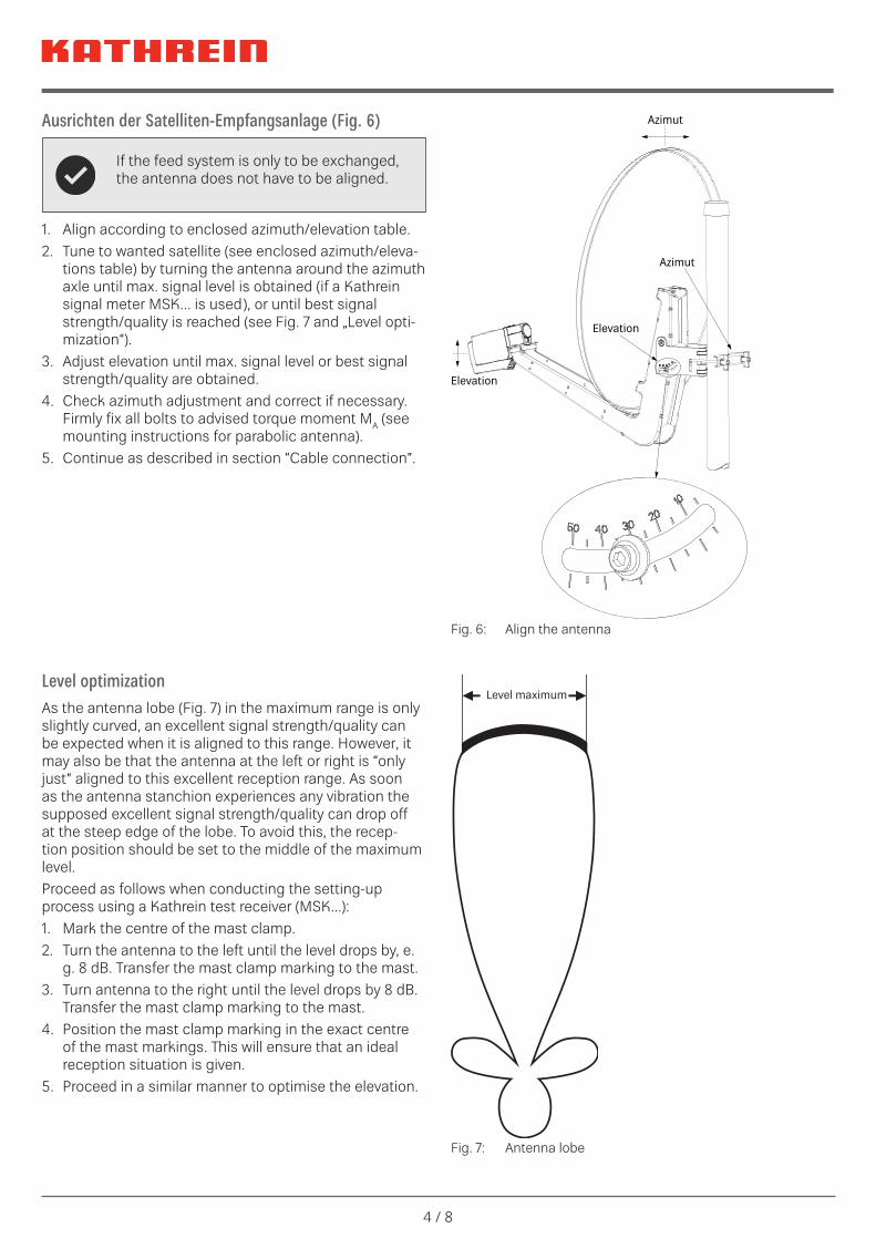
Ausrichten der Satelliten-Empfangsanlage (Fig. 6)
If the feed system is only to be exchanged, the antenna does not have to be aligned.
1. Align according to enclosed azimuth/elevation table.2. Tune to wanted satellite (see enclosed azimuth/eleva-
tions table) by turning the antenna around the azimuth axle until max. signal level is obtained (if a Kathrein signal meter MSK... is used), or until best signal strength/quality is reached (see Fig. 7 and „Level opti-mization“).
3. Adjust elevation until max. signal level or best signal strength/quality are obtained.
4. Check azimuth adjustment and correct if necessary.Firmly fix all bolts to advised torque moment MA (see mounting instructions for parabolic antenna).
5. Continue as described in section “Cable connection”.
Azimut
Azimut
Elevation
Elevation
Fig. 6: Align the antenna
Level maximum
Fig. 7: Antenna lobe
Level optimizationAs the antenna lobe (Fig. 7) in the maximum range is only slightly curved, an excellent signal strength/quality can be expected when it is aligned to this range. However, it may also be that the antenna at the left or right is “only just” aligned to this excellent reception range. As soon as the antenna stanchion experiences any vibration the supposed excellent signal strength/quality can drop off at the steep edge of the lobe. To avoid this, the recep-tion position should be set to the middle of the maximum level. Proceed as follows when conducting the setting-up process using a Kathrein test receiver (MSK...):1. Mark the centre of the mast clamp.2. Turn the antenna to the left until the level drops by, e.
g. 8 dB. Transfer the mast clamp marking to the mast.3. Turn antenna to the right until the level drops by 8 dB.
Transfer the mast clamp marking to the mast.4. Position the mast clamp marking in the exact centre
of the mast markings. This will ensure that an ideal reception situation is given.
5. Proceed in a similar manner to optimise the elevation.

5 / 8
Pre-setting the polarisation for compact feed systems in various countriesSa
telli
tes
Coun
try
TÜRK
SAT
42
° Ost
ASTR
A
28.2
° Ost
ASTR
A
23.5
° Ost
ASTR
A
19.2
° Ost
EUTE
LSAT
16
A 16
° Ost
EUTE
LSAT
H
OTB
IRD
13B
/ 13C
/ 13
D 13
° Ost
EUTE
LSAT
10
A 10
° Ost
EUTE
LSAT
7A
/ 7B
7° O
st
THO
R 5/
6
0.8°
Wes
t
EUTE
LSAT
5
Wes
t A
5° W
est
EUTE
LSAT
8
Wes
t A /
D 8°
Wes
t
HIS
PASA
T 1D
/ 1E
30
° Wes
t
Alba
nien
–23
–23
85
811
1522
2628
41Be
lgie
n–2
7–1
1–8
–5–9
–7–5
–24
810
25Bu
lgar
ien
–17
410
1410
1316
1925
2931
41Dä
nem
ark
–19
–4–1
2–3
–11
38
1113
24De
utsc
hlan
d–2
3–7
–40
–4–2
03
912
1428
Fran
krei
ch–3
2–1
6–1
1–9
–13
–10
–7–5
37
1027
Finn
land
–76
810
56
79
1214
1521
Grie
chen
land
–21
26
1411
1418
2128
3234
46G
roßb
ritan
nien
–26
–13
–10
–8–1
3–1
1–9
–7–2
13
17It
alie
n–2
9–1
0–4
–1–4
–13
615
1922
37Ir
land
–30
–17
–14
–12
–17
–15
–13
–11
–6–3
015
Kroa
tien
–24
–50
41
47
1017
2023
36Li
echt
enst
ein
–26
–10
–5–2
–6–3
02
1013
1631
Luxe
mbu
rg–2
6–1
1–7
–4–8
–6–3
–16
912
26M
onac
o–3
1–1
3–9
–5–9
–6–3
09
1316
32N
iede
rland
e–2
5–1
0–6
–4–8
–6–4
–15
810
24N
orw
egen
–11
24
61
24
59
1012
19Ö
ster
reic
h–2
4–6
–12
–20
36
1316
1832
Pole
n–1
70
47
25
79
1518
2031
Port
ugal
–43
–28
–24
–22
–26
–23
–20
–17
–8–3
024
Rum
änie
n–1
64
1013
911
1417
2326
2838
Schw
eden
–12
13
61
24
59
1113
21Sc
hwei
z–2
8–1
1–6
–3–7
–5–2
18
1215
30Se
rbie
n-M
onte
negr
o–2
1–1
59
58
1114
2124
2639
Slow
akei
–18
04
73
68
1117
2022
34Sl
owen
ien
–24
–5–1
3–1
25
815
1821
34Sp
anie
n–4
0–2
4–2
1–1
7–2
1–1
8–1
5–1
1–2
36
29Ts
chec
hien
–21
–40
40
25
7 13
1619
31U
ngar
n–2
0–1
37
36
911
1821
2335
Pola
risat
ion-
pres
ettin
gs fo
r com
pact
feed
sys
tem
s in
var
ious
Eur
opea
n co
untr
ies
(the
geo
grap
hica
l cen
tre
of e
ach
coun
try
is th
e po
int o
f ref
eren
ce in
eac
h ca
se).
In c
ase
of p
olar
isat
ion-
pres
ettin
gs e
xcee
ding
±25
°, th
e fe
ed s
yste
m is
to b
e se
t to
the
resp
ectiv
e st
op.
Tab.
1:
Pre-
setti
ng th
e po
laris
atio
n fo
r com
pact
feed
syst
ems i
n va
rious
cou
ntrie
s

6 / 8
Application examples
DC
Terr.
V high
H high
V low
H low18V
500mA max.
18VSAT 2 / 4
SAT 1 / 3
KAZ 11/12*
2xUAS582
KA
Z 1221810002
AK
AZ 11
507205A
8ESU 56
2ESU 53
1ESU 53
1ESU 51
EXD 1524
2ESU 51
2ESU 53
8ESU 53
Modus B (12 UB), Wideband, SAT 1+2
UAS 582 with Single-Cable Multi-Switch EXD 1524
UAS 582 with Single-Cable Multi-Switch EXD 1532
KAZ 11/12*
2xUAS582
KA
Z 1221810002
AK
AZ 11
507205A
2ESU 56
2ESU 56
2ESU 53
8ESU 53
EXD 1532
2ESU 51
4ESU 53
8ESU 53
Modus A (2 x 16 UB), Wideband, SAT 1+2
DC
Terr.
V high
H high
V low
H low
20510104
18V
500mA max.
18V
2ESU 51
2ESU 56

7 / 8
Technical data
Type | Order no. UAS 58220110032
Suitable for parabolic antennas CAS 60, CAS 80, CAS 90, CAS 120
Polarisation 1 x vertikal und 1 x horizontal
Input frequency GHz 10,70-12,75
Gain dB > 50
Output frequency MHz 300-2350
Oscillator frequency (L.O.) GHz 10,40
Phase noise (L.O.: 10,60 GHz) dBc 1 kHz: -50–10 kHz: -75–100 kHz: -95
System figure of merit (G/T) dB/K Siehe Offset-Parabolantennen
Polarisation decoupling dB min. 22
Output/impedance Ω 2 x F-Connector/75
Supply voltage LNB V 9 ... 19
Power consumption LNB W max. 1,2
Dimensions mm 235 x 135 x 44
Packing dimensions mm 295 x 185 x 65
Approx. weight kg 0,8
KAZ 11/12*
UAS582
POWER
STREAM
24
VH
ONE CABLEWIDEBAND
EXIP 4124
SAT>IP Server
BN: 20510136250-2300 MHz
14/18 V
2x 1 A max.5V 500mAUSB 2.0 ETHERNET RESET ON/OFF 12V 4A
KATHREIN-Werke KG
Anton-Kathrein-Straße 1-3
83022 Rosenheim, Germany
KA
Z 1221810002
AK
AZ 11
507205A
UAS 582 with SAT>IP-Server EXIP 4124
DisposalElectronic equipmentElectronic equipment is not domestic waste – in accordance with directive 2012/19/EC OF THE EUROPEAN PARLIAMENT AND THE COUNCIL dated 04th July 2012 concerning used electrical and electronic appliances, it must be dis- posed of properly. At the end of its service life, take this unit for disposal at a designated pub-lic collection point.

www.kathrein.com | [email protected] 9360000285/a/STD/1218/GB | Subject to change.
KATHREIN SE | Anton-Kathrein-Str. 1-3 | 83022 Rosenheim | Germany | Telefon +49 8031 184-0 | Fax +49 8031 184-52360
![The human liver fluke belongs to class (A) Cestoda (B ...€¦ · [] Contact. : 8400-582-582, 8604-582-582 To complete its life-cycle human liver fluke depends on (A) One intermediate](https://img.pdfslide.us/doc/110x75/6098e01de350ca75c81c8ca8/the-human-liver-fluke-belongs-to-class-a-cestoda-b-contact-8400-582-582.jpg)
![CHEMISTRY d & f block Coordination Compound · 2020. 5. 12. · d & f block Coordination Compound CHEMISTRY. 01 Contact. : 8400-582-582, 8604-582-582 [] Which of the following is](https://img.pdfslide.us/doc/110x75/5ff6cb16cefed51cb914ab14/chemistry-d-f-block-coordination-compound-2020-5-12-d-f-block-coordination.jpg)


![Among the following which compound can induce seed ...€¦ · [] Contact. : 8400-582-582, 8604-582-582 Among the following which compound can induce seed dormancy (A) Gibberellins](https://img.pdfslide.us/doc/110x75/5f1ff4a6591381304b4caebe/among-the-following-which-compound-can-induce-seed-contact-8400-582-582.jpg)


![Live Class 12:00 05:00 PM€¦ · [] Contact. : 8400-582-582, 8604-582-582 Catalytic efficiency of two different enzymes is compared by their (A) Product (B) Molecular size](https://img.pdfslide.us/doc/110x75/60d936f023313748a874a310/live-class-1200-0500-pm-contact-8400-582-582-8604-582-582-catalytic-efficiency.jpg)
![Crash Course Dr. Hariom Gangwar - NEET BOOSTER · 2021. 3. 12. · Q. 03 [] Contact. : 8400-582-582, 8604-582-582 Match the columns I and II, and choose the correct ... Coelenterata](https://img.pdfslide.us/doc/110x75/61389ef70ad5d20676495e2f/crash-course-dr-hariom-gangwar-neet-booster-2021-3-12-q-03-contact.jpg)