Embed Size (px)
Citation preview
UART/RS232/RS485/USB/Ethernet
Over Broadband Powerline Communication
Transceiver Module
Homeplug based Serial Adaptor
User Manual
LinkSprite Technologies, Inc
July 2009
www.linksprite.com
UART/RS232/RS485 Over Wide Band Powerline Communication Transceiver Module
LinkSpriteTechnologies, Inc. 2 www.linksprite.com
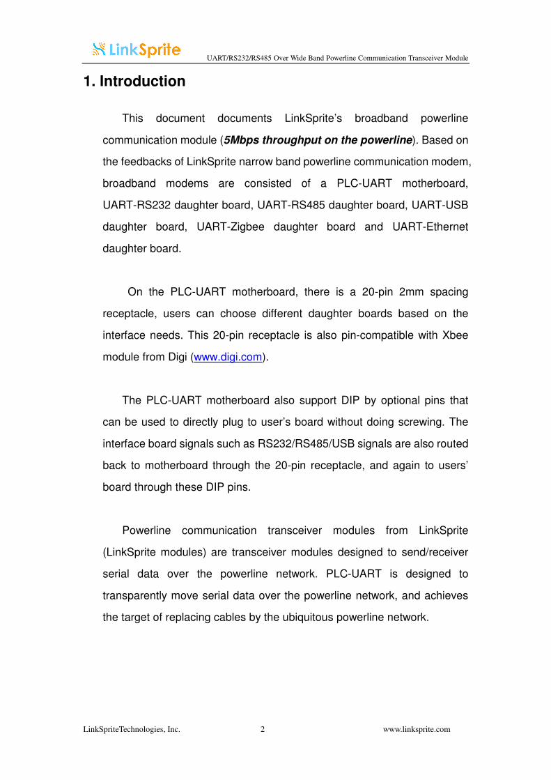
1. Introduction
This document documents LinkSprite’s broadband powerline
communication module (5Mbps throughput on the powerline). Based on
the feedbacks of LinkSprite narrow band powerline communication modem,
broadband modems are consisted of a PLC-UART motherboard,
UART-RS232 daughter board, UART-RS485 daughter board, UART-USB
daughter board, UART-Zigbee daughter board and UART-Ethernet
daughter board.
On the PLC-UART motherboard, there is a 20-pin 2mm spacing
receptacle, users can choose different daughter boards based on the
interface needs. This 20-pin receptacle is also pin-compatible with Xbee
module from Digi (www.digi.com).
The PLC-UART motherboard also support DIP by optional pins that
can be used to directly plug to user’s board without doing screwing. The
interface board signals such as RS232/RS485/USB signals are also routed
back to motherboard through the 20-pin receptacle, and again to users’
board through these DIP pins.
Powerline communication transceiver modules from LinkSprite
(LinkSprite modules) are transceiver modules designed to send/receiver
serial data over the powerline network. PLC-UART is designed to
transparently move serial data over the powerline network, and achieves
the target of replacing cables by the ubiquitous powerline network.
UART/RS232/RS485 Over Wide Band Powerline Communication Transceiver Module
LinkSpriteTechnologies, Inc. 3 www.linksprite.com
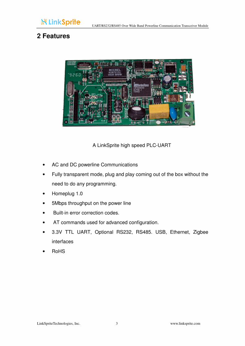
2 Features
A LinkSprite high speed PLC-UART
• AC and DC powerline Communications
• Fully transparent mode, plug and play coming out of the box without the
need to do any programming.
• Homeplug 1.0
• 5Mbps throughput on the power line
• Built-in error correction codes.
• AT commands used for advanced configuration.
• 3.3V TTL UART, Optional RS232, RS485. USB, Ethernet, Zigbee
interfaces
• RoHS
UART/RS232/RS485 Over Wide Band Powerline Communication Transceiver Module
LinkSpriteTechnologies, Inc. 4 www.linksprite.com
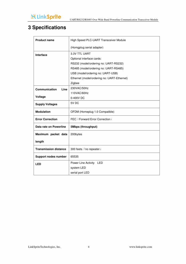
3 Specifications
Product name High Speed PLC-UART Transceiver Module
(Homgplug serial adapter)
Interface 3.3V TTL UART
Optional interface cards:
RS232 (model/ordering no: UART-RS232)
RS485 (model/ordering no: UART-RS485)
USB (model/ordering no: UART-USB)
Ethernet (model/ordering no: UART-Ethernet)
Zigbee
Communication Line
Voltage
230VAC/50Hz
110VAC/60Hz
0-400V DC
Supply Voltages 5V DC
Modulation OFDM (Homeplug 1.0 Compatible)
Error Correction FEC(Forward Error Correction)
Data rate on Powerline 5Mbps (throughput)
Maximum packet data
length
200bytes
Transmission distance 300 feets(no repeater)
Support nodes number 65535
LED Power Line Activity LED
system LED
serial port LED
UART/RS232/RS485 Over Wide Band Powerline Communication Transceiver Module
LinkSpriteTechnologies, Inc. 5 www.linksprite.com
4 Applications
• AMR
• Industry manufacture and control
• Safeguard, fire alarm, smoke alarm
• Collect and transmit instrument data
• Safeguard and monitor
• Home automation
• Solar/Wind electricity generation system
• Low latency servo control
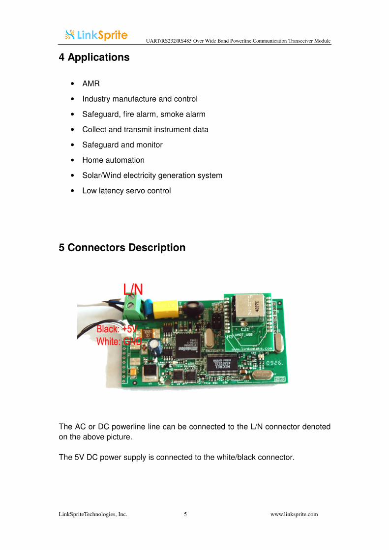
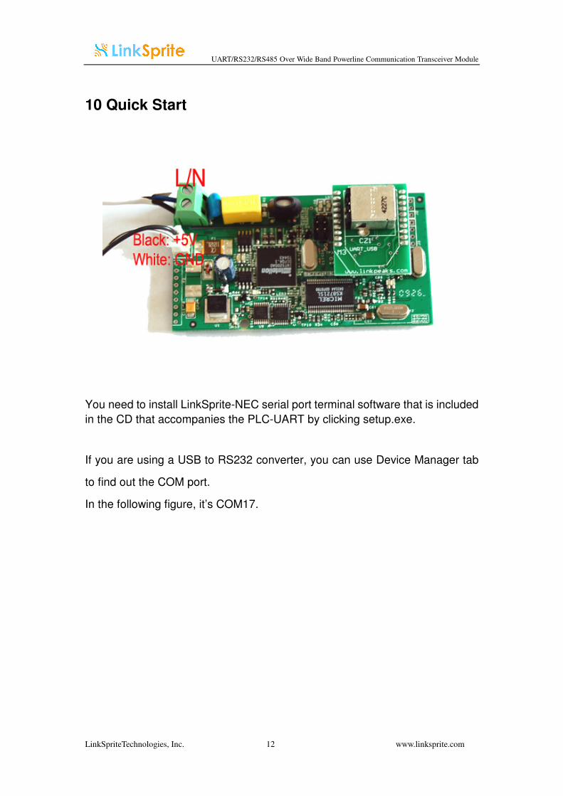
5 Connectors Description
The AC or DC powerline line can be connected to the L/N connector denoted
on the above picture.
The 5V DC power supply is connected to the white/black connector.
UART/RS232/RS485 Over Wide Band Powerline Communication Transceiver Module
LinkSpriteTechnologies, Inc. 6 www.linksprite.com
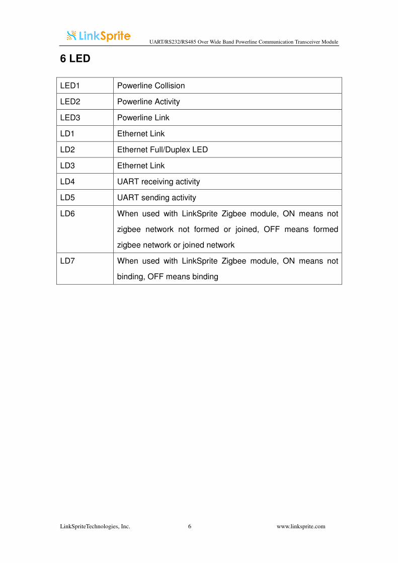
6 LED
LED1 Powerline Collision
LED2 Powerline Activity
LED3 Powerline Link
LD1 Ethernet Link
LD2 Ethernet Full/Duplex LED
LD3 Ethernet Link
LD4 UART receiving activity
LD5 UART sending activity
LD6 When used with LinkSprite Zigbee module, ON means not
zigbee network not formed or joined, OFF means formed
zigbee network or joined network
LD7 When used with LinkSprite Zigbee module, ON means not
binding, OFF means binding
UART/RS232/RS485 Over Wide Band Powerline Communication Transceiver Module
LinkSpriteTechnologies, Inc. 7 www.linksprite.com
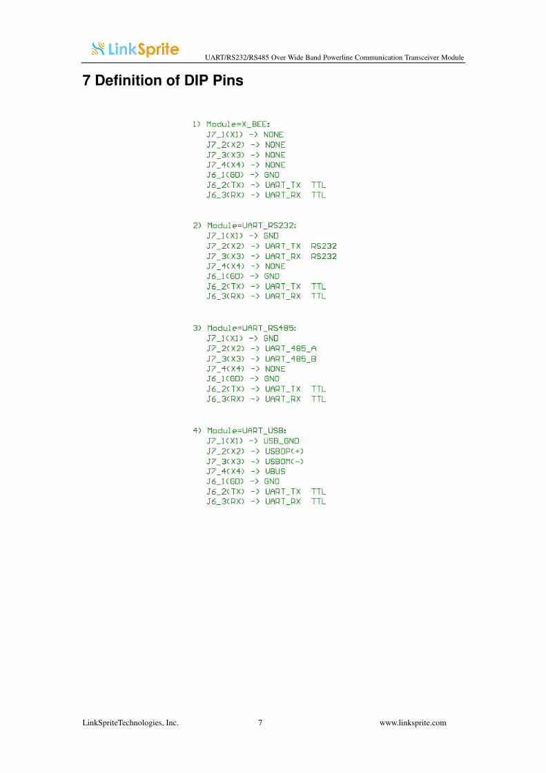
7 Definition of DIP Pins
UART/RS232/RS485 Over Wide Band Powerline Communication Transceiver Module
LinkSpriteTechnologies, Inc. 8 www.linksprite.com
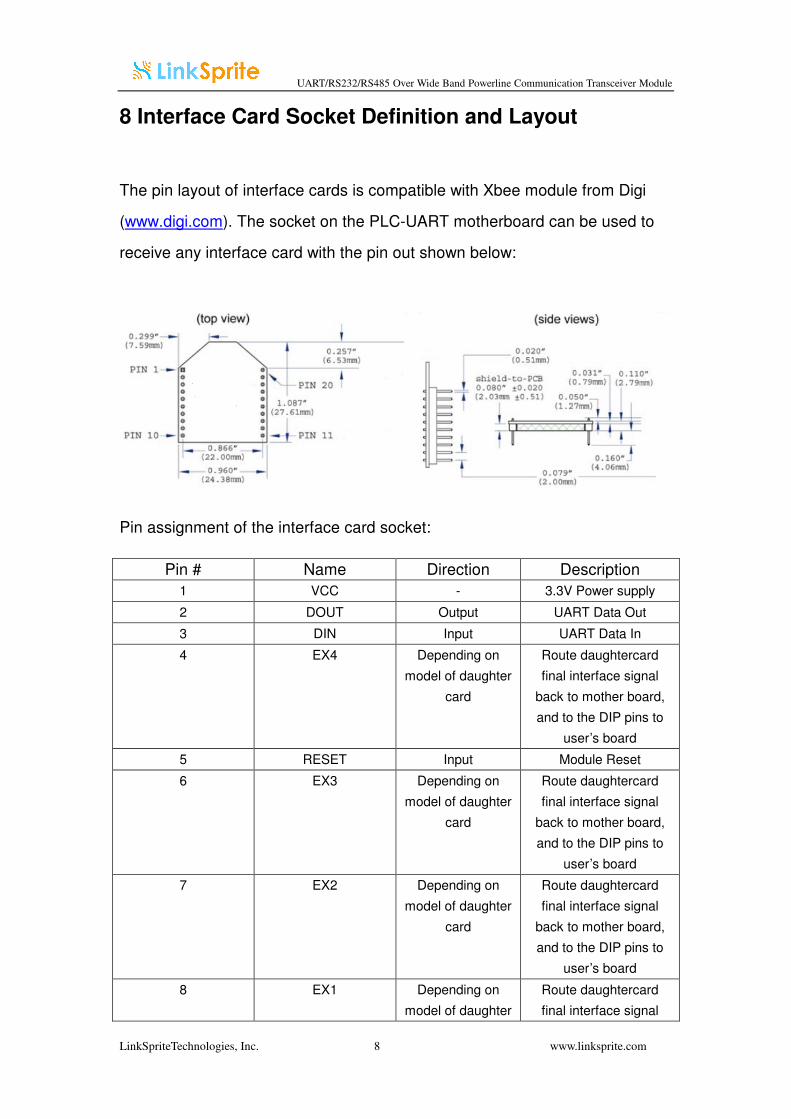
8 Interface Card Socket Definition and Layout
The pin layout of interface cards is compatible with Xbee module from Digi
(www.digi.com). The socket on the PLC-UART motherboard can be used to
receive any interface card with the pin out shown below:
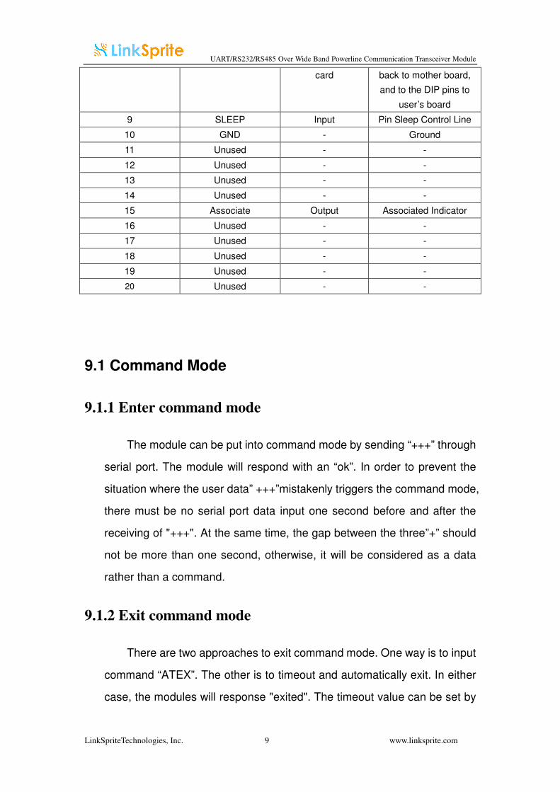
Pin assignment of the interface card socket:
Pin # Name Direction Description
1 VCC - 3.3V Power supply
2 DOUT Output UART Data Out
3 DIN Input UART Data In
4 EX4 Depending on
model of daughter
card
Route daughtercard
final interface signal
back to mother board,
and to the DIP pins to
user’s board
5 RESET Input Module Reset
6 EX3 Depending on
model of daughter
card
Route daughtercard
final interface signal
back to mother board,
and to the DIP pins to
user’s board
7 EX2 Depending on
model of daughter
card
Route daughtercard
final interface signal
back to mother board,
and to the DIP pins to
user’s board
8 EX1 Depending on
model of daughter
Route daughtercard
final interface signal
UART/RS232/RS485 Over Wide Band Powerline Communication Transceiver Module
LinkSpriteTechnologies, Inc. 9 www.linksprite.com
card back to mother board,
and to the DIP pins to
user’s board
9 SLEEP Input Pin Sleep Control Line
10 GND - Ground
11 Unused - -
12 Unused - -
13 Unused - -
14 Unused - -
15 Associate Output Associated Indicator
16 Unused - -
17 Unused - -
18 Unused - -
19 Unused - -
20 Unused - -
9.1 Command Mode
9.1.1 Enter command mode
The module can be put into command mode by sending “+++” through
serial port. The module will respond with an “ok”. In order to prevent the
situation where the user data” +++”mistakenly triggers the command mode,
there must be no serial port data input one second before and after the
receiving of "+++". At the same time, the gap between the three”+” should
not be more than one second, otherwise, it will be considered as a data
rather than a command.
9.1.2 Exit command mode
There are two approaches to exit command mode. One way is to input
command “ATEX”. The other is to timeout and automatically exit. In either
case, the modules will response "exited". The timeout value can be set by
UART/RS232/RS485 Over Wide Band Powerline Communication Transceiver Module
LinkSpriteTechnologies, Inc. 10 www.linksprite.com
command "ATTO"
9.2 Arguments and Responses
9.2.1 Arguments and Responses
For all the commands with arguments: if the parameters are correct,
the module will respond with an “ok”. Otherwise, the modules will response
with an “invalid para”. If there are no arguments associated with the
commands, it will be treated as polling modem and the module will
respond with the existing arguments residing in the module.
9.2.2 Commands without Arguments
There are four commands without arguments.
● + + +: enter command mode; will directly return “ok”.
● ATEX: exit the command mode, return “exited”.
● ATRS: software reset, will reset the module immediately, no return.
9.3 Modified arguments
Except for serial arguments, the modified arguments will be
immediately saved into eeprom and take effect. The serial arguments
won’t take effect immediately after being modified to avoid user from
modifying PC serial arguments before inputting command. Serial
arguments will take effect through automatically resetting module when
exiting the command mode.
UART/RS232/RS485 Over Wide Band Powerline Communication Transceiver Module
LinkSpriteTechnologies, Inc. 11 www.linksprite.com
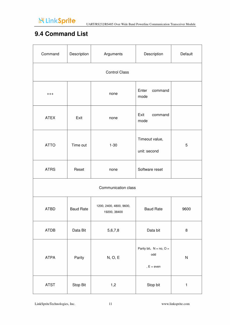
9.4 Command List
Command Description Arguments Description Default
Control Class
+++ none Enter command
mode
ATEX Exit none Exit command
mode
ATTO Time out 1-30
Timeout value,
unit: second
5
ATRS Reset none Software reset
Communication class
ATBD Baud Rate 1200, 2400, 4800, 9600,
19200, 38400 Baud Rate 9600
ATDB Data Bit 5,6,7,8 Data bit 8
ATPA Parity N, O, E
Parity bit,N = no, O =
odd
, E = even
N
ATST Stop Bit 1,2 Stop bit 1
UART/RS232/RS485 Over Wide Band Powerline Communication Transceiver Module
LinkSpriteTechnologies, Inc. 12 www.linksprite.com
10 Quick Start
You need to install LinkSprite-NEC serial port terminal software that is included
in the CD that accompanies the PLC-UART by clicking setup.exe.
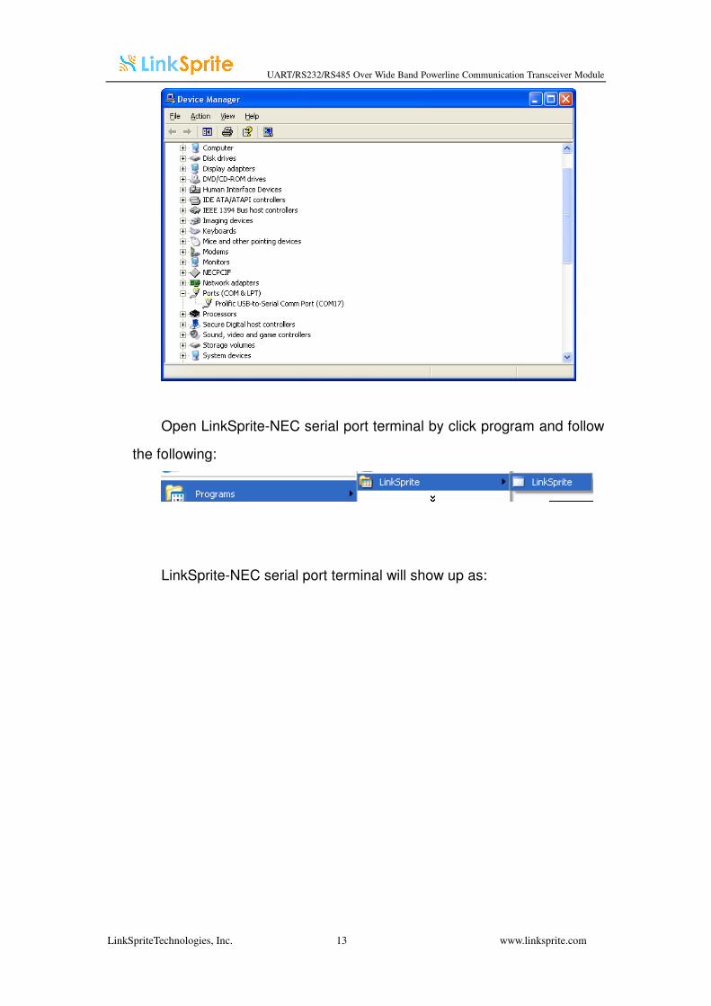
If you are using a USB to RS232 converter, you can use Device Manager tab
to find out the COM port.
In the following figure, it’s COM17.
UART/RS232/RS485 Over Wide Band Powerline Communication Transceiver Module
LinkSpriteTechnologies, Inc. 13 www.linksprite.com
Open LinkSprite-NEC serial port terminal by click program and follow
the following:
LinkSprite-NEC serial port terminal will show up as:
UART/RS232/RS485 Over Wide Band Powerline Communication Transceiver Module
LinkSpriteTechnologies, Inc. 14 www.linksprite.com
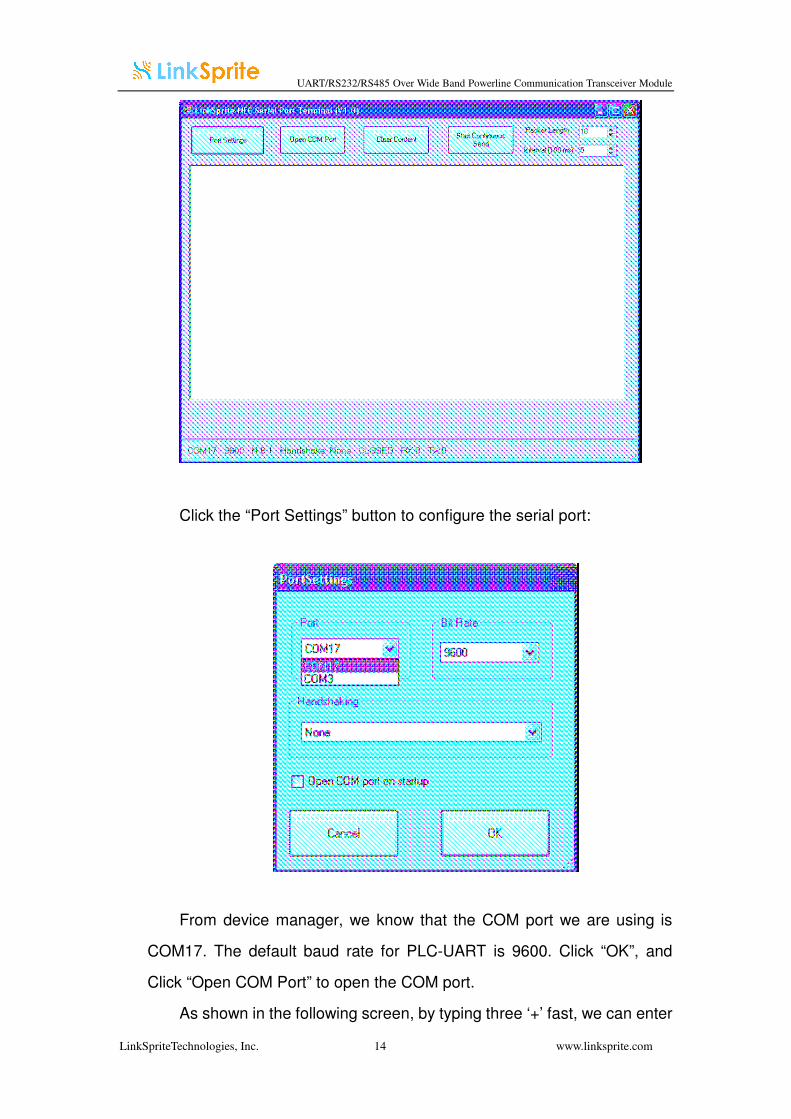
Click the “Port Settings” button to configure the serial port:
From device manager, we know that the COM port we are using is
COM17. The default baud rate for PLC-UART is 9600. Click “OK”, and
Click “Open COM Port” to open the COM port.
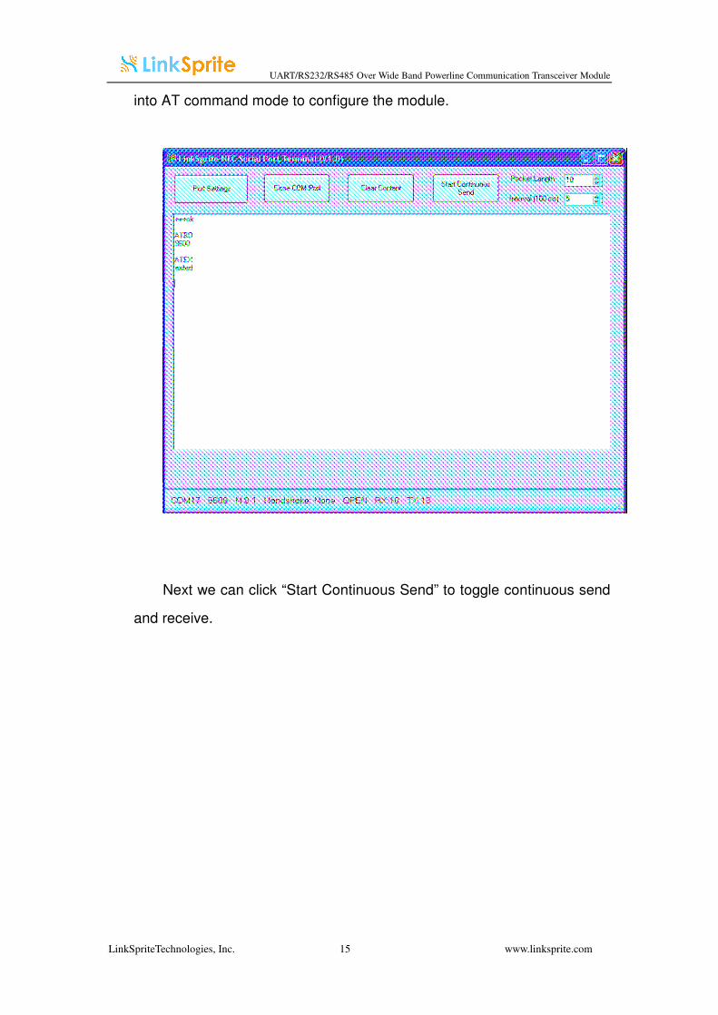
As shown in the following screen, by typing three ‘+’ fast, we can enter
UART/RS232/RS485 Over Wide Band Powerline Communication Transceiver Module
LinkSpriteTechnologies, Inc. 15 www.linksprite.com
into AT command mode to configure the module.
Next we can click “Start Continuous Send” to toggle continuous send
and receive.

UART/RS232/RS485 Over Wide Band Powerline Communication Transceiver Module
LinkSpriteTechnologies, Inc. 16 www.linksprite.com
LinkSprite Technolgies, Inc.
1410 Cannon Mountain Dr.
Longmont, CO 80503
(Voice) 720-949-4932
(Email) [email protected]
http://www.linksprite.com