Embed Size (px)
Citation preview

HUAWEI Module
UART Serial Port Design Guide
Issue 03
Date 2014-11-03

Copyright © Huawei Technologies Co., Ltd. 2014. All rights reserved.
No part of this manual may be reproduced or transmitted in any form or by any means without prior written
consent of Huawei Technologies Co., Ltd. and its affiliates ("Huawei").
The product described in this manual may include copyrighted software of Huawei and possible licensors.
Customers shall not in any manner reproduce, distribute, modify, decompile, disassemble, decrypt, extract,
reverse engineer, lease, assign, or sublicense the said software, unless such restrictions are prohibited by
applicable laws or such actions are approved by respective copyright holders.
Trademarks and Permissions
, , and are trademarks or registered trademarks of Huawei Technologies Co., Ltd.
Other trademarks, product, service and company names mentioned may be the property of their respective
owners.
Notice
Some features of the product and its accessories described herein rely on the software installed, capacities
and settings of local network, and therefore may not be activated or may be limited by local network
operators or network service providers.
Thus, the descriptions herein may not exactly match the product or its accessories which you purchase.
Huawei reserves the right to change or modify any information or specifications contained in this manual
without prior notice and without any liability.
DISCLAIMER
ALL CONTENTS OF THIS MANUAL ARE PROVIDED “AS IS”. EXCEPT AS REQUIRED BY APPLICABLE
LAWS, NO WARRANTIES OF ANY KIND, EITHER EXPRESS OR IMPLIED, INCLUDING BUT NOT
LIMITED TO, THE IMPLIED WARRANTIES OF MERCHANTABILITY AND FITNESS FOR A PARTICULAR
PURPOSE, ARE MADE IN RELATION TO THE ACCURACY, RELIABILITY OR CONTENTS OF THIS
MANUAL.
TO THE MAXIMUM EXTENT PERMITTED BY APPLICABLE LAW, IN NO EVENT SHALL HUAWEI BE
LIABLE FOR ANY SPECIAL, INCIDENTAL, INDIRECT, OR CONSEQUENTIAL DAMAGES, OR LOSS OF
PROFITS, BUSINESS, REVENUE, DATA, GOODWILL SAVINGS OR ANTICIPATED SAVINGS
REGARDLESS OF WHETHER SUCH LOSSES ARE FORSEEABLE OR NOT.
THE MAXIMUM LIABILITY (THIS LIMITATION SHALL NOT APPLY TO LIABILITY FOR PERSONAL
INJURY TO THE EXTENT APPLICABLE LAW PROHIBITS SUCH A LIMITATION) OF HUAWEI ARISING
FROM THE USE OF THE PRODUCT DESCRIBED IN THIS MANUAL SHALL BE LIMITED TO THE
AMOUNT PAID BY CUSTOMERS FOR THE PURCHASE OF THIS PRODUCT.
Import and Export Regulations
Customers shall comply with all applicable export or import laws and regulations and be responsible to
obtain all necessary governmental permits and licenses in order to export, re-export or import the product
mentioned in this manual including the software and technical data therein.
Privacy Policy
To better understand how we protect your personal information, please see the privacy policy at
http://consumer.huawei.com/privacy-policy.

HUAWEI Module UART Serial Port Design Guide About This Document
Issue 03 (2014-11-03) Huawei Proprietary and Confidential
Copyright © Huawei Technologies Co., Ltd. 3
About This Document
Revision History
Document Version
Date Chapter Description
01 2011-06-30 Creation
02 2011-07-22 4 Deleted 4 UART Multiplexing
03 2014-11-03 3 Added precautions for the UART connection
4 Added chapter 4:
Configurable Commands

HUAWEI Module UART Serial Port Design Guide Contents
Issue 03 (2014-11-03) Huawei Proprietary and Confidential
Copyright © Huawei Technologies Co., Ltd. 4
Contents
1 Overview ......................................................................................................................................... 6
2 Specifications ................................................................................................................................. 7
3 Circuit Design .............................................................................................................................. 10
3.1 Logic Levels ................................................................................................................................... 10
3.2 Connection Between Huawei Modules and Standard RS-232-C Interfaces ................................... 11
3.3 Connection Between Huawei Modules and Other DTE ................................................................. 13
4 Configurable Commands .......................................................................................................... 15
4.1 AT&C–Set DCD Line Mode ............................................................................................................ 15
4.1.1 Command Syntax .................................................................................................................. 15
4.1.2 Interface Description .............................................................................................................. 15
4.1.3 Parameter Description ........................................................................................................... 15
4.2 AT&D–Set DTR Line Mode ............................................................................................................ 16
4.2.1 Command Syntax .................................................................................................................. 16
4.2.2 Interface Description .............................................................................................................. 16
4.2.3 Parameter Description ........................................................................................................... 16
4.3 AT&S–Set DSR Line Mode ............................................................................................................ 16
4.3.1 Command Syntax .................................................................................................................. 16
4.3.2 Interface Description .............................................................................................................. 16
4.3.3 Parameter Description ........................................................................................................... 16
4.4 AT+IPR–Set DTE-DCE Baud Rate................................................................................................. 17
4.4.1 Command Syntax .................................................................................................................. 17
4.4.2 Interface Description .............................................................................................................. 17
4.4.3 Parameter Description ........................................................................................................... 17
4.5 AT+ICF–Set Character Frame Format ........................................................................................... 18
4.5.1 Command Syntax .................................................................................................................. 18
4.5.2 Interface Description .............................................................................................................. 18
4.5.3 Parameter Description ........................................................................................................... 18
4.6 AT+IFC–Control Local Flow ........................................................................................................... 19
4.6.1 Command Syntax .................................................................................................................. 19
4.6.2 Interface Description .............................................................................................................. 19
4.6.3 Parameter Description ........................................................................................................... 19

HUAWEI Module UART Serial Port Design Guide Contents
Issue 03 (2014-11-03) Huawei Proprietary and Confidential
Copyright © Huawei Technologies Co., Ltd. 5
4.7 AT\Q–Set Software or Hardware Flow Control ............................................................................... 20
4.7.1 Command Syntax .................................................................................................................. 20
4.7.2 Interface Description .............................................................................................................. 20
4.7.3 Parameter Description ........................................................................................................... 20
4.8 AT^HRIM–Set the RI Usage State .................................................................................................. 21
4.8.1 Command Syntax .................................................................................................................. 21
4.8.2 Interface Description .............................................................................................................. 21
4.8.3 Parameter Description ........................................................................................................... 21
5 Abbreviations .............................................................................................................................. 23

HUAWEI Module UART Serial Port Design Guide Overview
Issue 03 (2014-11-03) Huawei Proprietary and Confidential
Copyright © Huawei Technologies Co., Ltd. 6
1 Overview
Communications through Universal Asynchronous Receiver/Transmitter (UART) serial ports is convenient and reliable. UART serial ports are widely adopted in Huawei modules. This design guide describes the serial port specifications of Huawei modules and provides recommended design schemes for peripheral circuits. When designing UART serial ports for Huawei modules, customers can refer to this document.
Most of Huawei modules provide 8-wire serial ports with flow control. These 8-wire serial ports can also be used as 2-wire or 4-wire serial ports.
This document is applied to the following Huawei products.
Model Frequency bands
MC509 and MC509-a EVDO/CDMA2000 1X
MU509-b, MU509-c and MU509-g UMTS/HSDPA/GSM/GPRS/EDGE
MU609 UMTS/HSPA/GSM/GPRS/EDGE
MU709s-2 and MU709s-6 UMTS/HSPA+/GSM/GPRS/EDGE
ME909u-521 and ME909u-523 FDD-LTE/DC-HSPA+/HSPA+/HSPA/UMTS/GSM/GPRS/EDGE

HUAWEI Module UART Serial Port Design Guide Specifications
Issue 03 (2014-11-03) Huawei Proprietary and Confidential
Copyright © Huawei Technologies Co., Ltd. 7
2 Specifications
Most of Huawei modules provide 8-wire serial ports that can also be used as 2-wire or 4-wire serial ports.
Take the Huawei MU509 module as an example. Its main specifications include:
Full-duplex
Programmable data size
Programmable stop bits
Odd parity check, even parity check, or non-check
Variable baud rates (maximum 230.4 kbit/s; default 115.2 kbit/s)
Table 2-1 describes the signals of the Huawei MU509's UART serial port, in which the Huawei MU509 functions as Data Communication Equipment (DCE) and customers' PCs (hosts) function as Data Terminal Equipment (DTE). For definitions of the pins of other Huawei modules' serial ports, refer to the hardware guide of the modules.
Table 2-1 UART serial port signals
Name Description Feature Direction
UART_TX Data sending The DTE receives serial data.
DCEDTE
UART_RX Data receive The DTE transmits serial data.
DTEDCE
UART_RING Ringing indication The DTE is notified of a remote call or SMS.
DCEDTE
UART_RTS Data sending request The DTE notifies the DCE of sending requests.
DCEDTE
UART_DTR Data terminal ready The DTE is ready. DTEDCE
UART_CTS Clearing to send The DCE switches to the receiving mode.
DTEDCE
UART_DCD Data carrier detection Data links are connected, used to indicate data link state
DCEDTE

HUAWEI Module UART Serial Port Design Guide Specifications
Issue 03 (2014-11-03) Huawei Proprietary and Confidential
Copyright © Huawei Technologies Co., Ltd. 8
Name Description Feature Direction
UART_DSR Data ready on the wireless module
The DCE is ready. DCEDTE
Figure 2-1 to Figure 2-3 show the connection of the UART serial port in the Huawei module (DCE) with the host (DTE).
Figure 2-1 Connection of the 8-wire UART serial port in the Huawei module (DCE) with the host (DTE)
Figure 2-2 Connection of the 4-wire UART serial port in the Huawei module (DCE) with the host (DTE)
In a 4-wire serial port, DTE uses TXD, RXD, CTS, and RTS.

HUAWEI Module UART Serial Port Design Guide Specifications
Issue 03 (2014-11-03) Huawei Proprietary and Confidential
Copyright © Huawei Technologies Co., Ltd. 9
Figure 2-3 Connection of the 2-wire UART serial port in the Huawei module (DCE) with the host (DTE)
In a 2-wire serial port, DTE uses TXD and RXD, and cannot implement hardware flow
control. For massive data transfers, 4-wire or 8-wire serial ports that can provide hardware flow control are recommended.
You cannot use AT+IFC to enable hardware flow control when using a 2-wire serial port.
Otherwise, UART cannot communicate normally.
HUAWEI Module UART Serial Port Design Guide Circuit Design
Issue 03 (2014-11-03) Huawei Proprietary and Confidential
Copyright © Huawei Technologies Co., Ltd. 10
3 Circuit Design
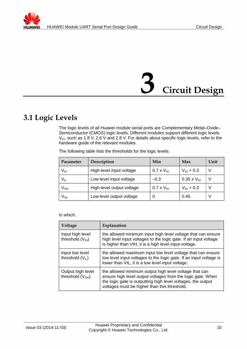
3.1 Logic Levels
The logic levels of all Huawei module serial ports are Complementary Metal–Oxide–Semiconductor (CMOS) logic levels. Different modules support different logic levels VIO, such as 1.8 V, 2.6 V and 2.8 V. For details about specific logic levels, refer to the hardware guide of the relevant modules.
The following table lists the thresholds for the logic levels.
Parameter Description Min Max Unit
VIH High-level input voltage 0.7 x VIO VIO + 0.3 V
VIL Low-level input voltage –0.3 0.35 x VIO V
VOH High-level output voltage 0.7 x VIO VIO + 0.3 V
VOL Low-level output voltage 0 0.45 V
In which,
Voltage Explanation
Input high level threshold (VIH)
the allowed minimum input high level voltage that can ensure high level input voltages to the logic gate. If an input voltage is higher than VIH, it is a high level input voltage.
Input low level threshold (VIL)
the allowed maximum input low level voltage that can ensure low level input voltages to the logic gate. If an input voltage is lower than VIL, it is a low level input voltage.
Output high level threshold (VOH)
the allowed minimum output high level voltage that can ensure high level output voltages from the logic gate. When the logic gate is outputting high level voltages, the output voltages must be higher than this threshold.

HUAWEI Module UART Serial Port Design Guide Circuit Design
Issue 03 (2014-11-03) Huawei Proprietary and Confidential
Copyright © Huawei Technologies Co., Ltd. 11
Voltage Explanation
Output low level threshold (VOL)
the allowed maximum output low level voltage that can ensure low level output voltages from the logic gate. When the logic gate is outputting low level voltages, the output voltages must be lower than this threshold.
3.2 Connection Between Huawei Modules and Standard RS-232-C Interfaces
The COM1 and COM2 interfaces of PCs comply with EIA-RS-232-C. Their logic levels are:
For TxD and RxD:
Logic 0 = –15 V to –3 V;
Logic 1 = +3 V to +15 V.
For control lines such as RTS, CTS, DSR, DTR, DCD and RING:
Signal enabled (connected, ON, positive voltages) = +3 V to +15 V;
Signal disabled (disconnected, OFF, negative voltages) = –15 V to –3 V.
RS232 chip can be used for connecting Huawei modules to standard RS-232-C interfaces.
If a 2-wire serial port is used, the MAX3232 chip is recommended. The signals from the module's UART_RXD pin are converted by the MAX3232 and then transferred to the DTE's RXD pin. The signals from DTE's TXD pin are converted by the MAX232 and then transferred to the module's UART_TXD pin.
The power supply of the MAX3232 is 3.3 V, not compatible with the logic level (VIO) of Huawei module serial ports. Therefore, after the signals from the UART_RXD pin go through the RS232 chip (MAX3232), a resistor circuit must be added to reduce the voltage from 3.3 V to VIO.
Figure 3-1 Connection of a 2-wire serial port
HUAWEI Module UART Serial Port Design Guide Circuit Design
Issue 03 (2014-11-03) Huawei Proprietary and Confidential
Copyright © Huawei Technologies Co., Ltd. 12
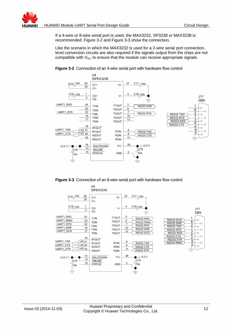
If a 4-wire or 8-wire serial port is used, the MAX3232, SP3238 or MAX3238 is recommended. Figure 3-2 and Figure 3-3 show the connection.
Like the scenario in which the MAX3232 is used for a 2-wire serial port connection, level conversion circuits are also required if the signals output from the chips are not compatible with VIO, to ensure that the module can receive appropriate signals.
Figure 3-2 Connection of an 4-wire serial port with hardware flow control
Figure 3-3 Connection of an 8-wire serial port with hardware flow control

HUAWEI Module UART Serial Port Design Guide Circuit Design
Issue 03 (2014-11-03) Huawei Proprietary and Confidential
Copyright © Huawei Technologies Co., Ltd. 13
3.3 Connection Between Huawei Modules and Other DTE
Most DTE uses single-chip microprocessors as central processing units (CPUs). Common serial port logic levels include 5 V, 3.3 V, 3 V, 2.85 V, 2.6 V and 1.8 V. Huawei modules and DTE should be connected based on the compatibility between their logic levels.
The DTE and DCE logic levels are compatible.
The DTE and DCE logic levels can be deemed compatible if the DTE voltage is equal to or approximately equal to the logic level (VIO) of the module serial port, that is, VOH > VIH and VOL < VIL. In this case, DTE and DCE can be connected using resistors or buffers.
The DTE and DCE logic levels are incompatible.
When the difference between DTE and DCE logic levels is great, a logic level conversion circuit may be required to match DTE and DCE logic levels. There are many methods and mature schemes to match logic levels, such as using logic level conversion ICs and resistors to divide voltages or using transistors and pull-up resistors. Customers can select schemes appropriate for their products.
This document provides a logic level conversion scheme using transistors and resistors for customers' reference. To prevent electric current from flowing backwards, circuits should be designed separately for the input and output of the module.
The module's input signals include UART_RX, UART_CTS and UART_DTR. Figure 3-4 shows a recommended conversion circuit for these input signals, in which VDD_IO is the reference voltage of the module's serial port.
Figure 3-4 Logic level conversion circuit for the input signals
The module's output signals include UART_TX, UART_RTS, UART_DSR, UART_DCD, and UART_RING. Figure 3-5 shows a recommended conversion circuit for these output signals, in which VDTE_IO is the reference voltage of the host's serial port.

HUAWEI Module UART Serial Port Design Guide Circuit Design
Issue 03 (2014-11-03) Huawei Proprietary and Confidential
Copyright © Huawei Technologies Co., Ltd. 14
Figure 3-5 Logic level conversion circuit for the output signals
It is suggested that users keep the UART external interface unconnected when design the
hardware, to ensure the convenience of later firmware upgrade and logs obtained.
It is suggested to connect UART and the host after the module is powered on (Vcc_1.8 and Vcc_2.8 output), to avoid rush-in of the current on the UART which may cause the module cannot powers on normally.
It is suggested that you keep the pins that you do not use unconnected.

HUAWEI Module UART Serial Port Design Guide Configurable Commands
Issue 03 (2014-11-03) Huawei Proprietary and Confidential
Copyright © Huawei Technologies Co., Ltd. 15
4 Configurable Commands
This chapter introduces the general UART commands. For the details of those commands, you can refer to the module's AT command interface specification.
4.1 AT&C–Set DCD Line Mode
4.1.1 Command Syntax
AT&C[<value>]
Possible Response(s)
<CR><LF>OK<CR><LF>
4.1.2 Interface Description
The AT&C command sets the relation between the status of the Data Carrier Detect
(DCD) line and signal detection of the remote receiving line.
4.1.3 Parameter Description
<value>: an integer type; If <value> is not specified, it is equivalent to set
<value> to 0.
0 Enable the DCD line.
1 The DCD line is enabled only when data carrier exists. (default value).
2 The DCD line is enabled only when there are one or more TCP or UDP connections if Huawei's proprietary protocol is used. If FTP or HTTP is used, the DCD line is effective only for data connections.

HUAWEI Module UART Serial Port Design Guide Configurable Commands
Issue 03 (2014-11-03) Huawei Proprietary and Confidential
Copyright © Huawei Technologies Co., Ltd. 16
4.2 AT&D–Set DTR Line Mode
4.2.1 Command Syntax
AT&D[<value>]
Possible Response(s)
<CR><LF>OK<CR><LF>
4.2.2 Interface Description
The AT&D command sets the result returned by the TA in data service state when the
Data Terminal Ready (DTR) circuit is disabled from enabling state.
4.2.3 Parameter Description
<value>: an integer type; If <value> is not specified, it is equivalent to set
<value> to 0.
0 TA ignores the status of the DTR circuit.
1 Enter the command mode while holding the current data conversation.
2 Release the data or voice conversation and enters the command mode. (default value)
4.3 AT&S–Set DSR Line Mode
4.3.1 Command Syntax
AT&S[<value>]
Possible Response(s)
<CR><LF>OK<CR><LF>
4.3.2 Interface Description
The AT&S command sets the status of the Data Set Ready (DSR) line according to
different communication status of the ME.
4.3.3 Parameter Description
<value>: an integer type; If <value> is not specified, it is equivalent to set
<value> to 0.

HUAWEI Module UART Serial Port Design Guide Configurable Commands
Issue 03 (2014-11-03) Huawei Proprietary and Confidential
Copyright © Huawei Technologies Co., Ltd. 17
0 DSR line always is ON. (default value)
1 DSR line is OFF when ME is in command mode; DSR line is ON when ME is in data mode.
4.4 AT+IPR–Set DTE-DCE Baud Rate
4.4.1 Command Syntax
AT+IPR=<rate>
Possible Response(s)
<CR><LF>OK<CR><LF>
In case of an MT-related error:
<CR><LF>+CME ERROR: <err><CR><LF>
AT+IPR?
Possible Response(s)
<CR><LF>+IPR: <rate><CR><LF><CR><LF>OK<CR><LF>
AT+IPR=?
Possible Response(s)
<CR><LF>+IPR: (list of supported auto-detectable <rate>s)[,(list of
supported fixed-only <rate>s)]<CR><LF><CR><LF>OK<CR><LF>
4.4.2 Interface Description
This command sets DTE-DCE (Data Terminal Equipment-Data Connection Equipment) baud rate.
The set command sets DTE-DCE baud rate.
The read command queries the current DTE-DCE baud rate.
The test command returns the DTE-DCE baud rate supported by this command.
4.4.3 Parameter Description
<rate>: an integer type, which is saved upon power failure.
0 Indicates adaptive baud rate.
Range of adaptive baud rate: 9600, 19200, 38400, 57600, and 115200.
Fixed baud rate: 9600, 19200, 38400, 57600, 115200 and 230400.
Default value: 115200.

HUAWEI Module UART Serial Port Design Guide Configurable Commands
Issue 03 (2014-11-03) Huawei Proprietary and Confidential
Copyright © Huawei Technologies Co., Ltd. 18
To set a fixed baud rate, ensure that the baud rates configured for the TE and TA are the
same.
To set an adaptive baud rate, run AT+IPR=0.
When running the AT command to set an adaptive baud rate and initializing the module, you must send AT command first to synchronize the buad rate of TE with that of TA (ensure that AT ahead of the command is in upper case)
After an adaptive baud rate is enabled, if you want to change the baud rate of the host, do the following: set the baud rate first, and then restart the module.
In multiplexing mode, only a fixed baud rate is supported.
You cannot use AT+IFC to enable hardware flow control when using a 2-wire serial port.
Otherwise, UART cannot communicate normally.
4.5 AT+ICF–Set Character Frame Format
4.5.1 Command Syntax
AT+ICF=<format>,<parity>
Possible Response(s)
<CR><LF>OK<CR><LF>
In case of an MT-related error:
<CR><LF>+CME ERROR: <err><CR><LF>
AT+ICF?
Possible Response(s)
<CR><LF>+ICF: <format>,<parity><CR><LF><CR><LF>OK<CR><LF>
AT+ICF=?
Possible Response(s)
<CR><LF>+ICF: (list of supported <format>s),(list of supported
<parity>s)<CR><LF><CR><LF>OK<CR><LF>
4.5.2 Interface Description
This command sets the character frame format of the serial ports.
4.5.3 Parameter Description
<format>: an integer type
0 Auto detect
1 8 Data 2 Stop

HUAWEI Module UART Serial Port Design Guide Configurable Commands
Issue 03 (2014-11-03) Huawei Proprietary and Confidential
Copyright © Huawei Technologies Co., Ltd. 19
2 8 Data 1 Parity 1 Stop
3 8 Data 1 Stop (default value)
4 7 Data 2 Stop
5 7 Data 1 Parity 1 Stop
6 7 Data 1 Stop
<partity>: an integer type
0 Odd parity (default value)
1 Even parity
4.6 AT+IFC–Control Local Flow
4.6.1 Command Syntax
AT+IFC=<DCE_by_DTE>,<DTE_by_DCE>
Possible Response(s)
<CR><LF>OK<CR><LF>
In case of an MT-related error:
<CR><LF>+CME ERROR: <err><CR><LF>
AT+IFC?
Possible Response(s)
<CR><LF>+IFC:
<DCE_by_DTE>,<DTE_by_DCE><CR><LF><CR><LF>OK<CR><LF>
AT+IFC=?
Possible Response(s)
<CR><LF>+IFC: (list of supported <DCE_by_DTE>s),(list of supported
<DTE_by_DCE>s)<CR><LF><CR><LF>OK<CR><LF>
4.6.2 Interface Description
This command sets the local flow control mode of the serial ports.
4.6.3 Parameter Description
<DCE_by_DTE>: an integer type specifies the method to be used by the DTE to
control the flow of received data from the DCE.
0 Disable flow control. (default value)

HUAWEI Module UART Serial Port Design Guide Configurable Commands
Issue 03 (2014-11-03) Huawei Proprietary and Confidential
Copyright © Huawei Technologies Co., Ltd. 20
1 XON/XOFF software flow control.
2 RTS line
<DTE_by_DCE>: an integer type specifies the method to be used by the DCE to
control the flow of transmitted data from the DTE.
0 Disable flow control. (default value)
1 XON/XOFF software flow control
2 CTS line
4.7 AT\Q–Set Software or Hardware Flow Control
4.7.1 Command Syntax
AT\Q[<n>]
Possible Response(s)
<CR><LF>OK<CR><LF>
In case of not supporting RTS/CTS when <n>=2:
<CR><LF>ERROR<CR><LF>
In case of an MT-related error:
<CR><LF>+CME ERROR: <err><CR><LF>
4.7.2 Interface Description
The AT\Q command sets software or hardware flow control mode.
4.7.3 Parameter Description
<n>: an integer type specifies the method to be used by the DTE to control the flow
of received data from the DCE.
0 Disable flow control. (default value)
1 XON/XOFF software flow control
2 Only CTS by DCE (TA)
3 RTS/CTS hardware flow control

HUAWEI Module UART Serial Port Design Guide Configurable Commands
Issue 03 (2014-11-03) Huawei Proprietary and Confidential
Copyright © Huawei Technologies Co., Ltd. 21
4.8 AT^HRIM–Set the RI Usage State
4.8.1 Command Syntax
AT^HRIM=<RI_Type>,<RI_Time>
Possible Response(s)
<CR><LF>OK<CR><LF>
In case of an MT-related error:
<CR><LF>+CME ERROR: <err><CR><LF>
AT^HRIM?
Possible Response(s)
<CR><LF>^HRIM: <RI_Type>,<RI_Time><CR><LF>^HRIM:
<RI_Type>,<RI_Time><CR><LF><CR><LF>OK<CR><LF>
In case of an MT-related error:
<CR><LF>+CME ERROR: <err><CR><LF>
AT^HRIM=?
Possible Response(s)
<CR><LF>^HRIM: (list of supported <RI_Type>s),(list of supported
<RI_Time>s)<CR><LF><CR><LF>OK<CR><LF>
In case of an MT-related error:
<CR><LF>+CME ERROR: <err><CR><LF>
4.8.2 Interface Description
This command sets the duration for how long the RI pin is kept at low voltage level when a short message or a voice call is coming in data mode.
The set command sets the duration for how long the RI pin is kept by the specified event at low voltage level.
The read command queries the event type that pulls down the RI pin voltage level and the duration for how long the RI pin is kept at that level.
The read command returns the parameter values supported by the command.
4.8.3 Parameter Description
<RI_Type>: an integer type specifies voice channel number. The value ranges from
0 to 1, and 0 indicates the first channel.
0 Enable the RI pin voltage level to be pulled down to indicate the arrival of new text messages.

HUAWEI Module UART Serial Port Design Guide Configurable Commands
Issue 03 (2014-11-03) Huawei Proprietary and Confidential
Copyright © Huawei Technologies Co., Ltd. 22
1 Enable the RI pin voltage level to be pulled down to indicate the arrival of new incoming calls.
<RI_Type>: an integer type specifies the duration for how long the RI pin is kept at
low voltage level. The value ranges from 1 ms to 50000 ms.

HUAWEI Module UART Serial Port Design Guide Abbreviations
Issue 03 (2014-11-03) Huawei Proprietary and Confidential
Copyright © Huawei Technologies Co., Ltd. 23
5 Abbreviations
Abbreviations Full Spelling
CMOS Complementary Metal Oxide Semiconductor
CPU Central Processing Unit
DCD Data Carrier Detect
DCE Data Communication Equipment
DTE Data Terminal Equipment
DSR Data Set Ready
UART Universal Asynchronous Receiver Transmitter
![ELECTENG 304 Computer Systems 2E - · PDF fileELECTENG 304 Computer Systems 2E ... two parallel I/O ports and one Serial I/O port using UART, ... UART code given in lecture 10 [4]](https://img.pdfslide.us/doc/110x75/5aac8a7d7f8b9a9c2e8d2e3e/electeng-304-computer-systems-2e-304-computer-systems-2e-two-parallel-io.jpg)