Embed Size (px)
Citation preview

1/16Registered Quality System to ISO 9001:2008
Form 1035sorinc.com913-888-2630
SOR® ultrasonic transmittersare a proven solution offering more flexibility and reliability than similar products. With unique features such as state-of-the-art programming, adaptive gain and a very powerful transmit pulse, they provide consistent operation under conditions where other ultrasonics fail.
Featu
res a
nd B
en
efits
Powerful transmitted pulse for greater flexibility
Low frequency sound for superior penetration in tough conditions
Automatic adaptive gain continually adjusts to process conditions
Superior application flexibility — automatic compensation for dust, foam, steam, fog and condensation
Two year warranty from date of manufacture.
Technology ComparisonechOsonix are unmatched in tough conditions where level measurement is critical. The following chart shows how echOsonix match up against other level transmitters.
Form 1035
U71
U73
Registered Quality System to ISO 9001:2008sorinc.com 913-888-2630
A = Excellent B = Average C = Poor X = Not Recommended
Oth
erU
ltras
onic
s
Rad
ar
RF
Cap
acita
nce
Diff
eren
tial
Pre
ssur
e
Lase
r
Easily selected for liquids, slurries or solids A B B C X A
Changing dielectric constant A A B X A A
Changing specific gravity A A A A X A
Dusty atmospheres A C C A X C
Water vapor (steam, fog, condensation, etc.) A C C A A X
Long measuring ranges (over 100 feet) A B B C C A
Poor surface conditions (foam, etc.) A C A B B X
High turbulence A B B C A B
Vessel intrusions A B B B A A
echO
soni
x
U71/U73 Ultrasonic Transmitter
2/16 Registered Quality System to ISO 9001:2008Form 1035 sorinc.com
913-888-2630
Theory of OperationechOsonix use pulses of sound to determine the distance to a target. They measure the time for the sound pulse to travel to the target and return as an echo. The distance is calculated using the measured time and speed of sound in the atmosphere of the vessel.
Any condition that affects the size of echo, creates false echoes or alters the speed of sound can cause problems with this process. In industrial applications, these situations are encountered often. The following pages show how echOsonix handle these issues, where they can be used successfully and what to avoid.
Features of echOsonixThere are three main features of echOsonix that allow it to outperform other level transmitters – high power signal, low frequency sound and adaptive gain control.
High PowerechOsonix produces the most intense sound pulse of all ultrasonic transmitters available. When conditions like dust or foam absorb sound, it makes sense to use as much energy as possible. This is a “bigger hammer” approach – when trying to get through a tough barrier, hit it with a bigger hammer!
Low FrequencyAirborne particles absorb sound. High frequency sound has a shorter wavelength and must travel farther to go the same linear distance. Therefore it hits more particles and loses more energy in a given distance.
This example shows high and low frequency sound traveling through dust. High frequency hits more dust particles and loses energy more quickly. This is why foghorns on ships have such low frequency, so the sound will travel farther through the water particles in fog. echOsonix uses lower frequency sound to provide better penetration through dust, steam and fog.
Principle
Sound Source Energy
Space Shuttle Launch 180 dB
Jet Engine at Takeoff 140
echOsonix Transmitter 138
Jackhammer 105
Normal Conversation 60
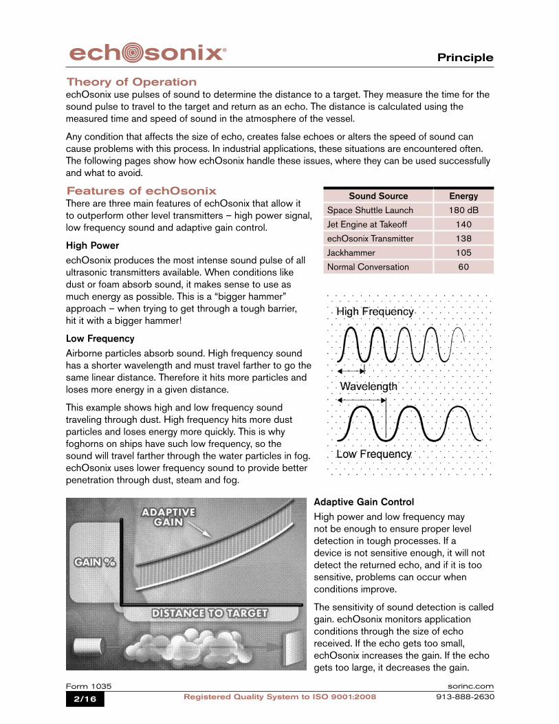
Adaptive Gain ControlHigh power and low frequency may not be enough to ensure proper level detection in tough processes. If a device is not sensitive enough, it will not detect the returned echo, and if it is too sensitive, problems can occur when conditions improve.
The sensitivity of sound detection is called gain. echOsonix monitors application conditions through the size of echo received. If the echo gets too small, echOsonix increases the gain. If the echo gets too large, it decreases the gain.

3/16Registered Quality System to ISO 9001:2008
Form 1035sorinc.com913-888-2630
Applications
Applications to Look For
echOsonix are suitable for many industrial applications. Its features allow this product to perform in many difficult applications. Some samples of applications where echOsonix excel are given here.
Powder and Bulk SolidsechOsonix are successful in a variety of bulk solids applications. They are routinely used to measure dusty and clean solids, large and small particle sizes, and extremely long ranges. Some common solids echOsonix applications are:Power – fly ash, coal, limestoneFood – whole kernel grains, various meals, flour, sugar, etc.Cement – powdered cement, fly ash, limestone, clinkersManufacturing – soda ash, sand, carbon black, bauxite, etc.Pulp & Paper – bentonite, wood chips, fines, etc.
Liquids/SlurriesMany industrial liquids applications have steam, fog and/or condensation present. echOsonix perform exceptionally well in liquid applications where the atmosphere gases will not be changing in composition (see below for details). Some typical applications where echOsonix offer unique advantages are:Power – cooling towers, sump pits, lime slurries, etc.Food – alcohol storage, waste oil pits, batching slurries, etc.Manufacturing – liquid latex, effluent, machine coolant, etc.Oil and Gas – crude oil sumps, water reclamation tanks, fuel oil
storage, etc.Water/Wastewater – chemical storage, digesters, sediment
ponds, etc.
If you want to know if echOsonix can handle your application, fill out the worksheet on page 14 of this catalog and forward it to either your local SOR representative or the factory.
Applications to AvoidAs with any technology, echOsonix are not a perfect fit for all applications. Below are some types of applications where ultrasonic transmitters, including echOsonix, may not be the best choice:Sealed tanks where the atmospheric gases are either layered or changing in composition –
the speed of sound in the tank is not constant and will cause erroneous readings.Very high pressure and/or temperature – these have a pronounced effect on sound waves. The
listed specifications for echOsonix should always be observed.Solids applications where the angle of repose (angle of the side of the pile of material) is greater than 45° and particle size is less than 1” (25mm). The sound is actually reflected away from the
instrument.

4/16 Registered Quality System to ISO 9001:2008Form 1035 sorinc.com
913-888-2630
Transducer Selection
The transducers produce the transmit pulse and detect returning echoes. They have a fixed frequency that determines the measured distance and what effects process conditions will have. echOsonix transducers are selected based on the range to be measured, the media type and the expected vessel conditions.
Transducer Selection for Liquids and SlurriesTypical Blanking – a dead zone where the transmitter cannot detect the process.
Foam/Condensate Range – some conditions, like foam, steam, fog and condensate, reduce the effective range of echOsonix. Use this value to determine the estimated effective range of the transducer when any of these conditions are present.
Ideal Conditions Range – ideal conditions for liquids and slurries are little or no foam, steam, fog or condensate. Use this maximum range to select a transducer for these conditions.
Transducer Selection for SolidsTypical Blanking – a dead zone where the transmitter cannot detect the process.
Heavy Dust/Small Particle Range – solids with heavy dust (visibility of 3 ft., 1m or less) and/or small particles (less than 1/16”, 1mm) reduce the effective range of echOsonix.
Ideal Conditions Range – ideal conditions for solids are when little or no dust is present and particle sizes are above 1/16”, 1mm. Use this maximum range to select a transducer for these conditions.
Transducer Frequency Typical Blanking Foam / Condensate Range Ideal Conditions Liquid & Slurries Range
30 kHz 18” (45cm) 6 ft. (1.8m) 33 ft. (10m)
20 kHz 24” (60cm) 33 ft. (10m) 65 ft. (20m)
15 kHz 24” (60cm) 50 ft. (15m) 100 ft. (30m)
10 kHz 48” (1.2m) 150 ft. (45m) 260 ft. (80m)
5 kHz 60” (1.5m) 260 ft. (80m) 260 ft. (80m)
Transducer Frequency Typical Blanking Heavy Dust / Small Particle Range
Ideal Conditions Solids Range
30 kHz 18” (45cm) 3 ft. (1m) 10 ft. (3m)
20 kHz 24” (60cm) 20 ft. (6m) 33 ft. (10m)
15 kHz 24” (60cm) 33 ft. (10m) 65 ft. (20m)
10 kHz 48” (1.2m) 65 ft. (20m) 100 ft. (30m)
5 kHz 60” (1.5m) 130 ft. (40m) 260 ft. (80m)
Agency Approvals
ATEX and FM (Pending)
Remote Class I, Groups A, B, C, and D;Class II, Groups E, F, and G;Class IIIDivision 2Provides Non-Incendive Outputs
Integral Class I, Groups B, C, and D;Class II, Groups E, F, and G;Class IIIDivisions 1 & 2
CSA

5/16Registered Quality System to ISO 9001:2008
Form 1035sorinc.com913-888-2630
Specifications
Product SpecificationsOperating Voltage 110 VAC Version 22-27 VDC and/or 100-126 VAC 220 VAC Version 22-27 VDC and/or 205 - 250 VACPower Consumptions 24 VDC Power Supply 10 W maximum 110/220 VAC Power Supply 10 VA maximum
Relay Output Integral Version 2 Form ‘C’ (SPDT) contacts rated 10A @ 240 VAC Remote Version 4 Form ‘C’ (SPDT) contacts rated 10A @ 240 VAC
All relays have independently adjustable deadbands.
Analog Output Isolated 4-20 mA or 20-4 mA (700 ohm)
Transducer Model
(Frequency)
Maximum Blanking Distance
Maximum Liquid / Slurry Range
Maximum Solid / Powder Range
SPL at 3 ft. (1m) in front of
transducerSPL at 3 ft. (1m)
to side of unit
A (5 kHz) 60 in. (1.52m) 260 ft. (80m) 260 ft. (80m) 137 dB 113 dB
B (10 kHz) 48 in. (1.22m) 260 ft. (80m) 100 ft.(30m) 138 dB 105 dB
K (15 kHz) 24 in. (0.61m) 100 ft. (30m) 65 ft. (20m) 135 dB 107 dB
C (20 kHz) 24 in. (0.61m) 65 ft. (20m) 33 ft. (10m) 132 dB 108 dB
D (30 kHz) 18 in. (0.46m) 33 ft. (10m) 10 ft. (3m) 129 dB 102 dB
Product Specifications
Design and specifications are subject to change without notice. For latest revision, see www.sorinc.com.
Weights
Range Electronics Package
Unit Weight* Electronics Cable (per 50 ft) Packaging Estimated
Weight
lbs kg lbs kg lbs kg lbs kg lbs kb
5 kHz Integral 24.5 11 - - - - 14 6.5 38.5 17.5
5 kHz Remote 20 9 4 1.75 2.25 1 14 6.5 40.25 18.25
10 kHz Integral 14.5 6.4 - - - - 7 3 21.5 9.4
10 kHz Remote 10 4.5 4 1.75 2.25 1 7 3 23.25 10
15 kHz Integral 10 4.5 - - - - 7 3 17 7.5
15 kHz Remote 5.5 2.5 4 1.75 2.25 1 7 3 18.75 8.25
20 kHz Integral 9 4 - - - - 4 2 13 6
20 kHz Remote 4.5 2 4 1.75 2.25 1 4 2 14.75 6.75
30 kHz Integral 8 3.5 - - - - 4 2 112 5.5
30 kHz Remote 3.5 1.5 4 1.75 2.25 1 4 2 13.75 6.25
Digital Output Modbus Communications
Electronic Accuracy +0.25% of maximum range
Remote Cable Length <100m (330 feet)
Remote Cable Type TYCAB DMC 71402 or Carol Cable C0784 7-conductor, 22 Ga. shielded cable
Memory Non-volatile with >10 years retention
Electrical Connections 2x3/4” NPT(F) on integral units Customer supplied on remote units
Operating Pressure 20” HgV to 15 psig
Operating Temperature Transducers -40°F (-40°C) to 140°F (60°C) Remote LCD Display +14°F (-10°C) to 140°F (60°C) Integral LCD Display -4°F (-20°C) to 140°F (60°C)
* Equipment mounted on top of vessel.
6/16 Registered Quality System to ISO 9001:2008Form 1035 sorinc.com
913-888-2630
Bridle
Stilling Well
Inlet Pipe
Min. 2”
Min. 4” Diameter
Min. 4” Diameter
MinimumHoles
Installation
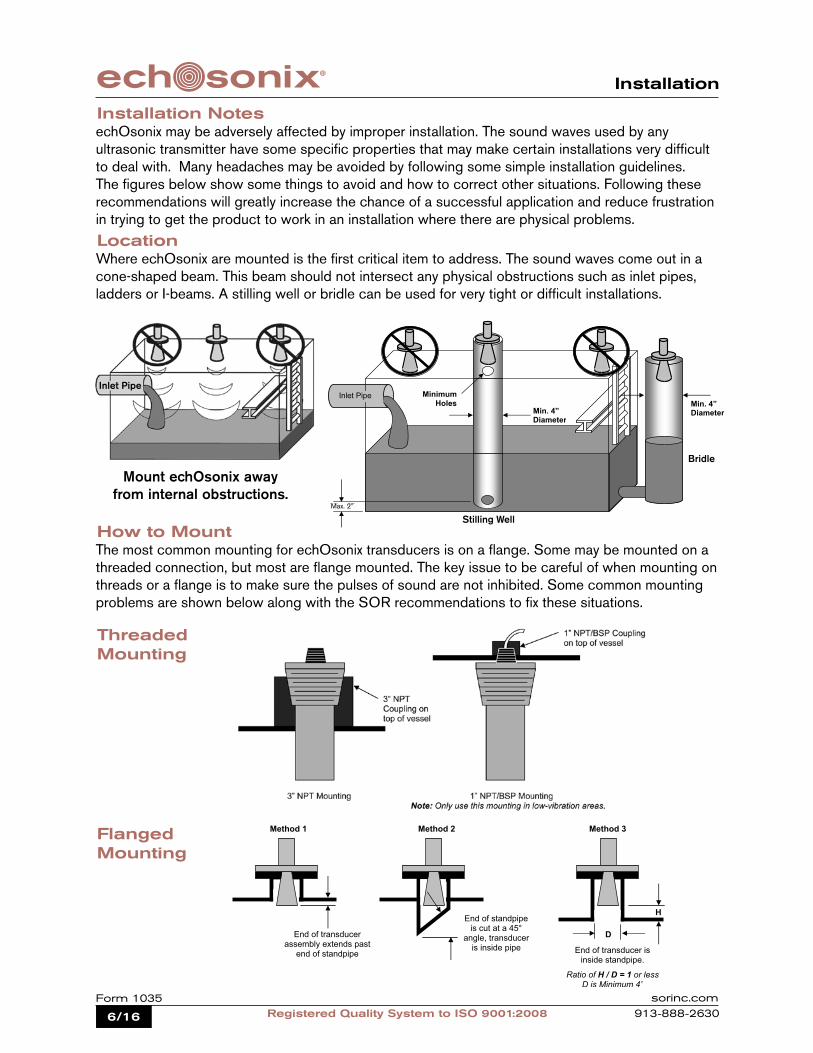
Installation NotesechOsonix may be adversely affected by improper installation. The sound waves used by any ultrasonic transmitter have some specific properties that may make certain installations very difficult to deal with. Many headaches may be avoided by following some simple installation guidelines. The figures below show some things to avoid and how to correct other situations. Following these recommendations will greatly increase the chance of a successful application and reduce frustration in trying to get the product to work in an installation where there are physical problems.
LocationWhere echOsonix are mounted is the first critical item to address. The sound waves come out in a cone-shaped beam. This beam should not intersect any physical obstructions such as inlet pipes, ladders or I-beams. A stilling well or bridle can be used for very tight or difficult installations.
Mount echOsonix away from internal obstructions.
How to MountThe most common mounting for echOsonix transducers is on a flange. Some may be mounted on a threaded connection, but most are flange mounted. The key issue to be careful of when mounting on threads or a flange is to make sure the pulses of sound are not inhibited. Some common mounting problems are shown below along with the SOR recommendations to fix these situations.
Flanged Mounting
Threaded Mounting
Inlet Pipe
Method 1 Method 2 Method 3
End of transducer assembly extends past
end of standpipe
End of standpipe is cut at a 45°
angle, transducer is inside pipe End of transducer is
inside standpipe.
Ratio of H / D = 1 or less D is Minimum 4”
H
D
Max. 2”
Stilling Well
Bridle
7/16Registered Quality System to ISO 9001:2008
Form 1035sorinc.com913-888-2630
Installation
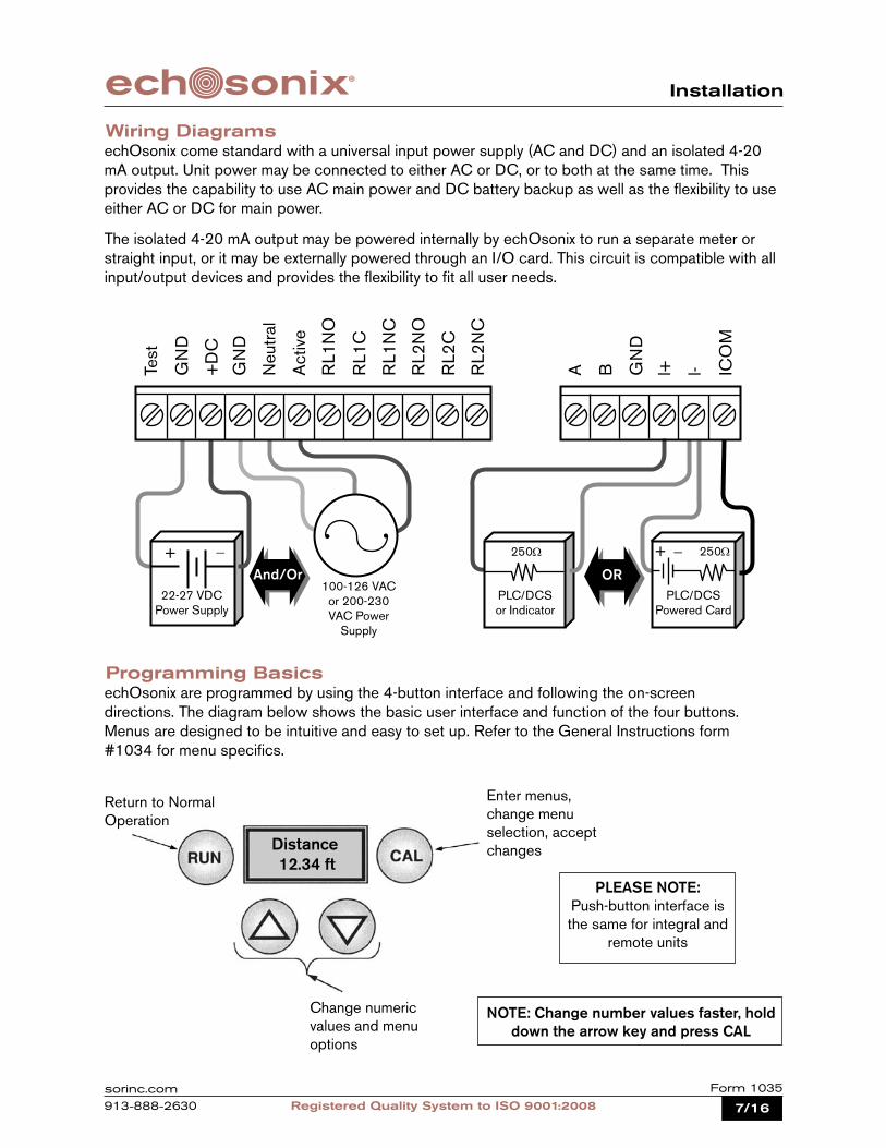
Wiring DiagramsechOsonix come standard with a universal input power supply (AC and DC) and an isolated 4-20 mA output. Unit power may be connected to either AC or DC, or to both at the same time. This provides the capability to use AC main power and DC battery backup as well as the flexibility to use either AC or DC for main power.
The isolated 4-20 mA output may be powered internally by echOsonix to run a separate meter or straight input, or it may be externally powered through an I/O card. This circuit is compatible with all input/output devices and provides the flexibility to fit all user needs.
Programming BasicsechOsonix are programmed by using the 4-button interface and following the on-screen directions. The diagram below shows the basic user interface and function of the four buttons. Menus are designed to be intuitive and easy to set up. Refer to the General Instructions form #1034 for menu specifics.
Return to Normal Operation
Enter menus, change menu selection, accept changes
Change numeric values and menu options
Distance 12.34 ft
PLEASE NOTE: Push-button interface is the same for integral and
remote units
100-126 VAC or 200-230 VAC Power
Supply
OR
Test
ICO
M
l-l+GN
D
BARL2
NC
RL2
C
RL2
NO
RL1
NC
RL1
C
RL1
NO
Act
ive
Neu
tral
+D
C
GN
D
GN
D
22-27 VDCPower Supply
PLC/DCSor Indicator
PLC/DCSPowered Card
250Ω+ _ 250Ω
And/Or
+ _
NOTE: Change number values faster, hold down the arrow key and press CAL

8/16 Registered Quality System to ISO 9001:2008Form 1035 sorinc.com
913-888-2630
How to Order
Ultrasonic
Input Power
None All associated agency listings
30 kHz
20 kHz
15 kHz
10 kHz
5 kHz
NEMA 4 / Explosion Proof with Window (Integral Only)
NEMA 4 / Explosion Proof without Window (Integral Only)
NEMA 4X (Remote Only)
Level Measurement
echoOsonix are selected as two separate model numbers - one for the electronics package and one for the transducer.
echOsonix Level Transmitter; line-powered integral unit; weathertight and explosion-proof housing with window; 110 VAC and/or 24 VDC power supply with 4-20 mA and two discrete outputs, 20 kHz sensor range; all associated agency listings and a paper supplemental tag.
U71 - CL7J - ZZ - 20 - PPModel Number System
Transmitter Type 1
Line Powered
2 7
4 C
D
Housing
F
5L
67 110 VAC and / or 24 VDC
220 VAC and / or 24 VDC8
7J 4-20 mA with Discrete Outputs
800
930
20
15
10
05
U
Power Type
7
Integral
Remote
3 1
3
Mounting
Level Measurement
ZZ
Output Type
10C4
PP
RR
VV
Compliance/Conformance Test Certificate
Paper tag
Wired-on SS tag
Fungicidal varnish on housing
Accessories
Transducer Frequency
Input Power
Agency Approvals*
Level Measurement
ModelNumber
*Match electronics and transducer approvals to maintain the agency listing integrity.
U 7 1 C L 7 J ZZ 20 PP

9/16Registered Quality System to ISO 9001:2008
Form 1035sorinc.com913-888-2630
How to Order
None All associated agency listings
30 kHz
20 kHz
15 kHz
10 kHz
5 kHz
13 Sensor Material of Construction
Polypropylene sensor bodyTeflon face for 30, 20, 15 kHz
Rubber face for 10, 5 kHz
Teflon wetted parts require 4” 150# style flange
P
T
14346FG
15A NPT pipe thread (3” size only)
150# ANSI style FF polypropylene flangeC
16ZZ
Focusing cone for 30, 20, 15 kHz transducers (minimum 4” flange on 20, 15 kHz)
Paper tag (remote only)
Wired-on SST tag (remote only)
17XXX.X
Process Connection Size
18FC
Integral Mount
Remote Mount
11 B
R
Transducer Type
3” (standard on 30, 20, 15 kHz transducers)4” (flange only - required on 20, 15 kHz with FC option)
6” (flange only)8” (flange only)
10” (flange only - standard on 10, 5 kHz transducers)
00000
Agency Approvals*
Integral-mount transducer; 20kHz; polypropylene sensor; 3” NPT(M) Process Connection; all associated agency listings; no transducer cable and no accessories.
BCP - 3A - ZZ - 00000Model Number System
PP
RR
Cable Length
Remote transducer cable length in feet (330 ft. maximum)
Integral transducer (no cable required)
00
Transducer Range
30 kHz
20 kHz
15 kHz
10 kHz
5 kHz
12
Process Connection Type
None
All associated agency listings
Accessories
D
C
K
B
A
B C P 3 A ZZ 00000 PP Model Number
*Match electronics and transducer approvals to maintain the agency listing integrity.
10/16 Registered Quality System to ISO 9001:2008Form 1035 sorinc.com
913-888-2630
Dimensions
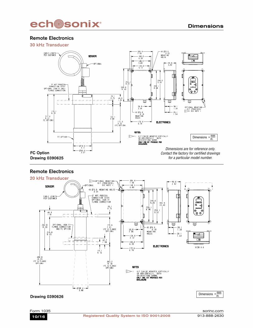
Remote Electronics30 kHz Transducer
Dimensions = mm in.
Drawing 0390625
Remote Electronics20 kHz Transducer
Drawing 0390626
FC OptionDimensions are for reference only.
Contact the factory for certified drawings for a particular model number.
Dimensions = mm in.
11/16Registered Quality System to ISO 9001:2008
Form 1035sorinc.com913-888-2630
Dimensions
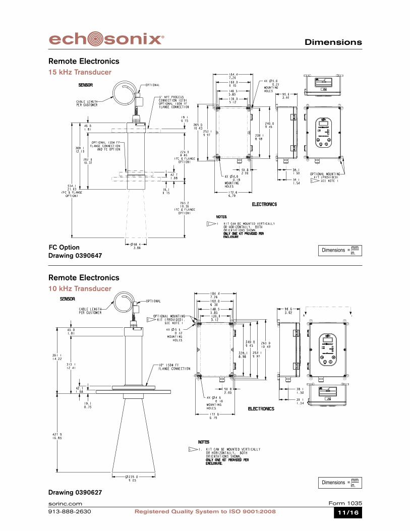
Remote Electronics10 kHz Transducer
Drawing 0390627
Remote Electronics15 kHz Transducer
Drawing 0390647FC Option Dimensions = mm
in.
Dimensions = mm in.

12/16 Registered Quality System to ISO 9001:2008Form 1035 sorinc.com
913-888-2630
Dimensions
Remote Electronics5 kHz Transducer
Integral Electronics30 kHz Transducer
Drawing 0390628Dimensions = mm
in.
Dimensions = mm in.Drawing 0390629
FC Option

13/16Registered Quality System to ISO 9001:2008
Form 1035sorinc.com913-888-2630
Dimensions
Integral Electronics20 kHz Transducer
Integral Electronics15 kHz Transducer
Drawing 0390646 Dimensions = mm in.
Dimensions = mm in.Drawing 0390630
14/16 Registered Quality System to ISO 9001:2008Form 1035 sorinc.com
913-888-2630
Dimensions
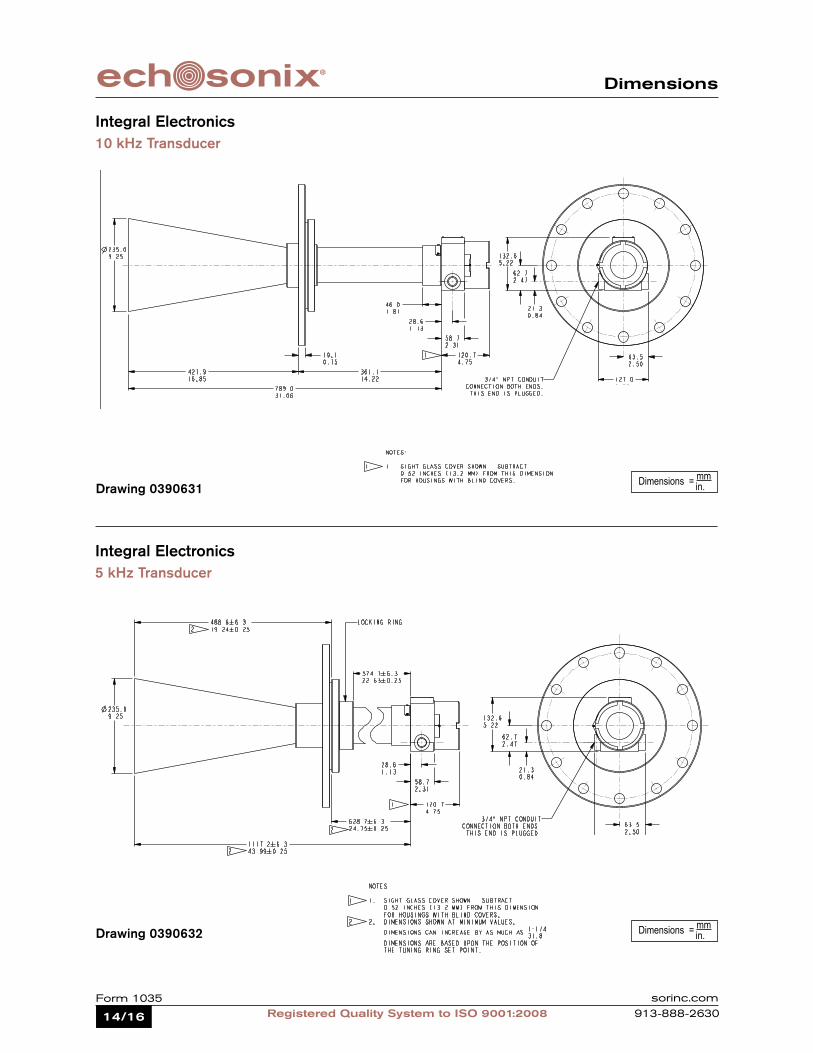
Integral Electronics10 kHz Transducer
Integral Electronics5 kHz Transducer
Drawing 0390631Dimensions = mm
in.
Drawing 0390632 Dimensions = mm in.

15/16Registered Quality System to ISO 9001:2008
Form 1035sorinc.com913-888-2630
Application Worksheet
Application Worksheet
Company Name Contact
Industry Phone
Address FAX
Vessel Shape (check the one that applies, or sketch vessel below) Installation Information
Vessel Height Measured Range Vessel Diameter
Vessel Material . . . qSS qOther Metal qConcrete qOther
Mounting . . . qStand Pipe qCoupling qBracket qOther
Connection Size / Type Stand Pipe Diameter / Length
Input Power . . . q110VAC q220VAC q24 VDC Line Power q 24 VDC Loop Power
Output Type . . .q4-20 mA qRelay # of Relays qModbus
Remote Electronics . . . Distance
Integral Electronics
Area . . . q NEMA 4X Classification . . . qClasses I, II & III; Div. 2 qClasses I, II & III; Div. 1 & 2 q
Sight Window . . . qY q N
Application Notes and Sketch
Please fax your completed worksheet to the number below.
14685 W. 105th Street, Lenexa, KS 66215 • 913-888-2630 • 800-676-6794 • Fax 913-888-0767 • www.sorinc.com
Instrument Requirements
Registered Quality System to ISO 9001:2000 Form 1248 (01.08) ©2008 SOR, Inc. Printed in USA
Material Monitored qSolid qLiquid qSlurry
Tag No. Dust . . . qHeavy qMedium qLight
Temperature Foam . . . Thickness qDense qLight
Pressure Condensation . . . qY qNAgitation . . . qY qN Atmosphere . . . qAirOther Homogenous . . . qY qN
Process Information
CylinderCone-bottom
CylinderSection Cylinder
“Bullet” Tank Box Cone-bottom Box
Dual-outlet Box
q q q q q q q

16/16 Registered Quality System to ISO 9001:2008Form 1035 sorinc.com
913-888-2630
echOsonix® Level Transmitters
TemperatureSwitches
Pre
ssu
re
Flow
LevelLevel
Switches
Flow Switches
PressureSwitches
SOR® offers a full line of commercial-grade process instruments.
Tem
pera
ture
Registered Quality System to ISO 9001:2008 Form 1035 (02.11) ©2011 SOR Inc.
We Deliver Quality On Time
SOR Europe, Ltd.Farren CourtCowfoldWest Sussex RH13 8BPUnited Kingdom
Phone +44 (0) 1403 864000Fax +44 (0) 1403 864040
SOR - ChinaRoom 903, No. 10 Building Wan Da Plaza No. 93 Jian Guo RoadChao Yang DistrictBeijing, China 100022
Phone +86 (10) 5820 8767Fax +86 (10) 58 20 8770
SOR Inc.14685 West 105th StreetLenexa, Kansas 66215
Phone 913-888-2630Toll Free 800-676-6794Fax 913-888-0767
sorinc.com
Process Instrumentation