Embed Size (px)
Citation preview

O W N E R ’ S M A N U A L
4-Channel Line Mixer with FireWire
OO MAX
+14-14 +14-14
MID
LOW
HIGH
EQ
GAIN
LEVEL
U U
U U
U U
U
U
U
OO MAX
1 2 3 4
U
OO MAX
LEVELU
OO MAX
U
+14-14
U
+14-14
MID
LOW
HIGH
EQ
GAIN
+10KILL
U
+10KILL
U U
U
+10KILL
U
+10KILL
U
+10KILL
U
+10KILL
+10KILL +10KILL
+10KILL +10KILL
+10KILL +10KILL
LEVELSET
LEVELSET
AUX
OO MAX OO MAX
AUX
OO MAX OO MAX
OL
10
7
4
0
4
10
20
POWER
L R
MAXFW IN
MAXOO
OO MAXPHONESOO
LOOPOUT
� U.4�0 4-Channel Line Mixer
U.4
20
4-C
han
ne
l Lin
e M
ixe
r
1. Readtheseinstructions.
2. Keeptheseinstructions.
3. Heedallwarnings.
4. Followallinstructions.
5. Donotusethisapparatusnearwater.
6. Cleanonlywithadrycloth.
7. Donotblockanyventilationopenings.Installinaccordancewiththemanufacturer’sinstructions.
8. Donotinstallnearanyheatsourcessuchasradiators,heatregisters,stoves,orotherapparatus(includingamplifiers)thatproduceheat.
9. Donotdefeatthesafetypurposeofthepolarizedorgrounding-typeplug.Apolarizedplughastwobladeswithonewiderthantheother.Agrounding-typeplughastwobladesandathirdgroundingprong.Thewidebladeorthethirdprongareprovidedforyoursafety.Iftheprovidedplugdoesnotfitintoyouroutlet,consultanelectricianforreplacementoftheobsoleteoutlet.
10.Protectthepowercordfrombeingwalkedonorpinchedparticularlyatplugs,conveniencereceptacles,andthepointwheretheyexitfromtheapparatus.
11.Onlyuseattachments/accessoriesspecifiedbythemanufacturer.
12.Useonlywithacart,stand,tripod,bracket,ortablespecifiedbythemanufacturer,orsoldwiththeapparatus.Whenacartisused,usecautionwhenmovingthecart/apparatuscombinationtoavoidinjuryfromtip-over.
13.Unplugthisapparatusduringlightningstormsorwhenunusedforlongperiodsoftime.
14.Referallservicingtoqualifiedservicepersonnel.Servicingisrequiredwhentheapparatushasbeendamagedinanyway,suchaspower-supplycordorplugisdamaged,liquidhasbeenspilledorobjectshavefallenintotheapparatus,theapparatushasbeenexposedtorainormoisture,doesnotoperatenormally,orhasbeendropped.
15.Thisapparatusshallnotbeexposedtodrippingorsplashing,andnoobjectfilledwithliquids,suchasvasesorbeerglasses,shallbeplacedontheapparatus.
16.TheACadapterisusedasthepowerdisconnectdeviceandshouldremainreadilyaccessibletotheuser.
17.ThisapparatusdoesnotexceedtheClassA/ClassB(whicheverisapplicable)limitsforradionoiseemissionsfromdigitalapparatusassetoutintheradiointerferenceregulationsoftheCanadianDepartmentofCommunications.
ATTENTION—Le présent appareil numérique n’émet pas de bruits radioélectriques dépassant las limites applicables aux appareils numériques de class A/de class B (selon le cas) prescrites dans le réglement sur le brouillage radioélectrique édicté par les ministere des communications du Canada.
18.Exposuretoextremelyhighnoiselevelsmaycausepermanenthearingloss.Individualsvaryconsiderablyinsusceptibilitytonoise-inducedhearingloss,butnearlyeveryonewilllosesomehearingifexposedtosufficientlyintensenoiseforaperiodoftime.TheU.S.Government’sOccupationalSafetyandHealthAdministration(OSHA)hasspecifiedthepermissiblenoiselevelexposuresshowninthefollowingchart.
AccordingtoOSHA,anyexposureinexcessofthesepermissiblelimitscouldresultinsomehearingloss.Toensureagainstpotentiallydanger-ousexposuretohighsoundpressurelevels,itisrecommendedthatallpersonsexposedtoequipmentcapableofproducinghighsoundpres-surelevelsusehearingprotectorswhiletheequipmentisinoperation.Earplugsorprotectorsintheearcanalsorovertheearsmustbewornwhenoperatingtheequipmentinordertopreventpermanenthearinglossifexposureisinexcessofthelimitssetforthhere.
ImportantSafetyInstructions
Duration Per Day Sound Level dBA, Typical In Hours Slow Response Example
8 90 Duoinsmallclub
6 92
4 95 SubwayTrain
3 97
2 100 Veryloudclassicalmusic
1.5 102
1 105 DavescreamingatSteveaboutdeadlines
0.5 110
0.25orless 115 Loudestpartsatarockconcert
WARNING—Toreducetheriskoffireorelectricshock,donotexposethisapparatus
torainormoisture.
PORTABLE CART WARNING
Carts and stands - TheComponent should be usedonly with a cart or standthat is recommended bythe manufacturer.A Component and cartcombination should bemoved with care. Quickstops, excessive force, anduneven surfaces may causethe Component and cartcombination to overturn.
CAUTION AVISRISK OF ELECTRIC SHOCK
DO NOT OPENRISQUE DE CHOC ELECTRIQUE
NE PAS OUVRIR
CAUTION: TO REDUCE THE RISK OF ELECTRIC SHOCKDO NOT REMOVE COVER (OR BACK)
NO USER-SERVICEABLE PARTS INSIDEREFER SERVICING TO QUALIFIED PERSONNEL
ATTENTION: POUR EVITER LES RISQUES DE CHOCELECTRIQUE, NE PAS ENLEVER LE COUVERCLE. AUCUN
ENTRETIEN DE PIECES INTERIEURES PAR L'USAGER. CONFIERL'ENTRETIEN AU PERSONNEL QUALIFIE.
AVIS: POUR EVITER LES RISQUES D'INCENDIE OUD'ELECTROCUTION, N'EXPOSEZ PAS CET ARTICLE
A LA PLUIE OU A L'HUMIDITE
The lightning flash with arrowhead symbol within an equilateral triangle is intended to alert the user to the presence of uninsulated"dangerous voltage" within the product's enclosure, that may be of sufficient magnitude to constitute a risk of electric shock to persons.
Le symbole éclair avec point de flèche à l'intérieur d'un triangle équilatéral est utilisé pour alerter l'utilisateur de la présence à l'intérieur du coffret de "voltage dangereux" non isolé d'ampleur suffisante pour constituer un risque d'éléctrocution.
The exclamation point within an equilateral triangle is intended to alert the user of the presence of important operating and maintenance (servicing) instructions in the literature accompanying the appliance.
Le point d'exclamation à l'intérieur d'un triangle équilatéral est employé pour alerter les utilisateurs de la présence d'instructions importantes pour le fonctionnement et l'entretien (service) dans le livret d'instruction accompagnant l'appareil.

Part No. SW0556 Rev. D 02/08 ©2007-2008 LOUD Technologies Inc. All Rights Reserved.
�Owner’s Manual
Ow
ne
r’s Man
ual
Need help with your new U.4�0 Mixer?• Visit www.mackie.com and click Support to find:
FAQs, manuals, addendums, and user forums.
• Email us at: [email protected].• Telephone 1-800-898-��11 to speak with one of our splendid
technical support representatives, (Monday through Friday, from 7 a.m. to 5 p.m. PST).
ContentsIMPORTANTSAFETYINSTRUCTIONS........................ 2INTRODUCTION...................................................... 4FEATURES............................................................... 4GETTINGSTARTED................................................... 5HOOKUPDIAGRAMS............................................... 6REARPANELFEATURES......................................... 10
1.INSTRUMENT/LINEINPUT......................... 102.LINEINPUTS.............................................. 103.PHONOINPUTS......................................... 104.GNDTERMINAL......................................... 105.AUXOUTPUTS........................................... 106.MAINOUTS............................................... 117.HEADPHONESOUTPUT.............................. 118.DCINPUT.................................................. 119.FIREWIRECONNECTION............................. 11
TOPPANELFEATURES........................................... 12CHANNELCONTROLS..................................... 1210.LEVELSETLED......................................... 1211.INSTRUMENTSWITCH............................. 1212.GAIN...................................................... 123-BANDEQ................................................... 1313.HIGHEQ................................................. 1314.MIDEQ................................................... 1315.LOWEQ.................................................. 1316.AUX........................................................ 1317.LEVEL...................................................... 13CONTROLSECTION........................................ 1418.POWERLED............................................. 1419.METERS.................................................. 1420.FWIN..................................................... 1421.FWLOOPOUT......................................... 1422.PHONESLEVEL........................................ 1523.MAINLEVEL............................................ 1524.FAIRYDUST............................................. 15
APPENDIXA:SERVICEINFORMATION.................... 16APPENDIXB:CONNECTIONS.................................. 18APPENDIXC:TECHNICALINFO............................... 19APPENDIXD:FIREWIRE........................................ 21SOFTWAREINSTALLATION..................................... 24U.420LIMITEDWARRANTY................................... 27

4 U.4�0 4-Channel Line Mixer
U.4
20
4-C
han
ne
l Lin
e M
ixe
r IntroductionThank you for choosing a Mackie U.420 mixer. It
contains all your favorite features in a ultra-compact 4-channel line mixer, along with a built-in FireWire interface, and a phono input for turntablists.
The U.420 is equally at home in recording studio ap-plications or in live performances:
In the studio, the mixer offers Mackie-quality sound to sub-mix outboard gear and bring it into the computer. It has 4 stereo inputs that can accept any stereo device from synths, samplers, or a turntable. Channel 1 accepts an instrument connection without the need for a DI box.
In live performances, the mixer will enable you to sub-mix synths, computers, samplers, pedal boards, turntables, cd-players, and effects on stage. Bands and solo artists from DJs, electronic artists and singer songwriters can use the mixer to sub-mix their creative tools and deliver them to the sound board. The mixer’s aux bus allows you to set up a separate mix to feed stage monitors or external processors.
You will find that the U.420 mixer is a very useful piece of equipment, and we hope you will love it, just as much as we did making it for you.
FEATURES• 4 stereo line-level input channels.
• Built-in FireWire 2x2 interface provides easy input from computer to the main mix, and easy outputs to the computer from the main mix. It has 24-bit resolution, and 44.1, 48, 88.2, and 96 kHz sample rates.
• Separate FireWire modes for live performance or overdubbing.
• Ultra-compact design, with functional and ergonomic controls.
• 3-Band EQ on each channel, with kill position.
• Phono preamplifier on channel 4 accepts phono-level stereo signals from a turntable.
• Instrument-level input option on channel 1.
• Stereo aux bus allows a separate mix to be sent to stage monitors or external processors.
• TRS stereo main outputs.
• TRS stereo headphone output.
• TRS stereo aux bus outputs.
• Level-set LEDs and gain controls allow easy optimization of each channel.
• Stereo main meters with overload lights.
• Large, easy to use, main level control.
• External power supply.
• Includes Tracktion, our professional, easy-to-use, totally-amazing music production software.
HOW TO USE THIS MANUALPlease read the safety instructions on page 2 first.
The getting started guide on page 5 will help you get the mixer set up fast so you can start using it right away. Right after that are the ever popular hook-up diagrams that show you some typical setups.
The features section describes every knob, button, and connection point on the mixer, roughly following the signal flow through the mixer from top to bottom. For more information about a feature, locate its number in the appropriate illustration, and find it in the nearby paragraphs.
This icon marks information that is critically important or unique to the mixer. For your own good, read them and remember them.
This icon leads you to in-depth explanations of features and practical tips. They usually have some valuable nuggets of information.
Appendix A shows service and repair information.Appendix B is a section on connectors.Appendix C shows the specs and a block diagram.Appendix D shows details of the FireWire interface.
Please write your serial number here for future reference (i.e., insurance claims, tech support, return authorization, etc.) Purchased at: Date of purchase:
5Owner’s Manual
Ow
ne
r’s Man
ual
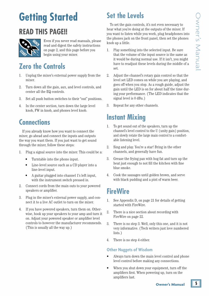
GettingStartedREADTHISPAGE!!
Even if you never read manuals, please read and digest the safety instructions on page 2, and this page before you begin using your mixer.
ZerotheControls1. Unplug the mixer’s external power supply from the
mixer.
2. Turn down all the gain, aux, and level controls, and center all the EQ controls.
3. Set all push button switches to their “out” positions.
4. In the center section, turn down the large level knob, FW in knob, and phones level knob.
ConnectionsIf you already know how you want to connect the
mixer, go ahead and connect the inputs and outputs the way you want them. If you just want to get sound through the mixer, follow these steps:
1. Plug a signal source into the mixer. This could be a:
• Turntable into the phono input.
• Line-level source such as a CD player into a line-level input.
• A guitar plugged into channel 1’s left input, with the instrument switch pressed in.
2. Connect cords from the main outs to your powered speakers or amplifier.
3. Plug in the mixer’s external power supply, and con-nect it to a live AC outlet to turn on the mixer.
4. If you have powered speakers, turn them on. Other-wise, hook up your speakers to your amp and turn it on. Adjust your powered speaker or amplifier level controls to however the manufacturer recommends. (This is usually all the way up.)
SettheLevelsTo set the gain controls, it’s not even necessary to
hear what you’re doing at the outputs of the mixer. If you want to listen while you work, plug headphones into the phones jack on the front panel, then set the phones knob up a little.
1. Play something into the selected input. Be sure that the volume of the input source is the same as it would be during normal use. If it isn’t, you might have to readjust these levels during the middle of a set.
2. Adjust the channel’s rotary gain control so that the level set LED comes on while you are playing, and goes off when you stop. As a rough guide, adjust the gain until the LED is on for about half the time dur-ing your performance. (The LED indicates that the signal level is 0 dBu.)
3. Repeat for any other channels.
InstantMixing1. To get sound out of the speakers, turn up the
channel’s level control to the U (unity gain) position, and slowly rotate the large main control to a comfort-able listening level.
2. Sing and play. You’re a star! Bring in the other channels, and generally have fun.
3. Grease the frying pan with hog fat and turn up the heat just enough to not fill the kitchen with fine blue smoke.
4. Cook the sausages until golden brown, and serve with black pudding and a pint of warm beer.
FireWire1. See Appendix D, on page 21 for details of getting
started with FireWire.
2. There is a nice section about recording with FireWire on page 22.
3. There is no step 3. Well, only this one, and it is not very informative. (Tech writers just love numbered lists.)
4. There is no step 4 either.
Other Nuggets of Wisdom• Always turn down the main level control and phone
level control before making any connections.
• When you shut down your equipment, turn off the amplifiers first. When powering up, turn on the amplifiers last.

� U.4�0 4-Channel Line Mixer
U.4
20
4-C
han
ne
l Lin
e M
ixe
r HookupDiagrams
Production studio
This diagram shows a stereo synth, and a drum machine connected to channels 1 & 2, and a turntable connected to the phono inputs of channel 4. The stereo aux output sends signals to the effects/sampler, and the wet signal is returned into channel 3.
The main outputs are fed to a pair of Mackie HR studio monitors for control room listening, and the mixer’s Big Knob controls their volume. The headphone out has its own level control, independent of the Big Knob.
A laptop is connected via FireWire. The U.420 provides stereo mains to the computer for record-ing with most DAW applications like Tracktion, Cubase, or Sonar. This is independent of the Big Knob as well. Additionally, there is a stereo return from the laptop that has its own mix level control into the mains.
The FireWire loop through switch on the top of the mixer makes overdubbing a breeze. In its normal out position, you can play back the mix from your DAW and it will not create a feedback loop. Only the analog inputs 1-4 will be available for recording. Track it!
Oh, and don’t forget this FireWire return can be used for any playback software application like Ableton Live, Tracktor, or iTunes.
GND
PHONO
R
1234
R
L
POWER18V,1.5A
OUTMAIN
OUTAUX
(MONO)
R
L(MONO)L
R
L (MONO)L (MONO)L
R R
Headphones
ground wire
Turntable with phono-level out
Laptop
Keyboard
Drum machine
HR824Powered
Monitors
Effects/ Sampler

7Owner’s Manual
Ow
ne
r’s Man
ual
Live performance system
This diagram shows a guitar connected to channel 1, plus a stereo synth and drum machine connected to channels 2 & 3. A turntable is connected to the phono inputs on channel 4. Use the left aux send to connect to a Mackie SRM450 for stage monitoring. The U.420 will automatically sum the stereo signal to mono if you use the left aux output only.
The main outputs are fed to a pair of Mackie SRM450s for the audience’s listening pleasure. The mixer’s Big Knob controls their volume. The headphone out has its own level control, independent of the Big Knob.
A laptop is connected via FireWire. The U.420 provides stereo mains to the computer for recording with most DAW applications like Tracktion, Cubase or Sonar. Perfect for recording your set. Any play-back software applications like Ableton Live or Tracktor can easily be part of your performance by utiliz-ing the FireWire stereo return that has its own mix level control into the mains.
The FireWire loop through switch on the top of the mixer allows you to send your FireWire return through the FireWire output for recording. So use Ableton Live and your analog inputs to perform, and record it all at the same time on Tracktion or your DAW of choice. The switch should be pressed in to allow loop through of the FireWire return to the FireWire record output.
GND
PHONO
R
1234
R
L
POWER18V,1.5A
OUTMAIN
OUTAUX
(MONO)
R
L(MONO)L
R
L (MONO)L (MONO)L
R R
ground wire
Turntable with phono-level out Keyboard
Drum machine
Guitar
SRM450Powered
Speakers
SRM450 PoweredStage Monitor
Headphones
Laptop
8 U.4�0 4-Channel Line Mixer
U.4
20
4-C
han
ne
l Lin
e M
ixe
r
Keyboardist’s submixer
GND
PHONO
R
1234
R
L
POWER18V,1.5A
OUTMAIN
OUTAUX
(MONO)
R
L(MONO)L
R
L (MONO)L (MONO)L
R R
Main Mixto
front-of-housemixer
Personal Stereo Monitors(SRM150 powered monitors)
Laptop
Organ
Keyboard Controller
Nord Lead
Electronic Piano
AcousticGuitar
GND
PHONO
R
1234
R
L
POWER18V,1.5A
OUTMAIN
OUTAUX
(MONO)
R
L(MONO)L
R
L (MONO)L (MONO)L
R R
Analog SynthKeyboard workstation
Rhodes
HR824studiomonitors
Aux tostudio mixer
Laptop
Keyboard Controller
Electronic Piano
Headphones
Keyboard recording station
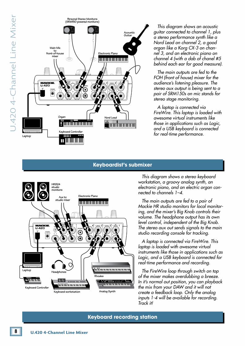
This diagram shows an acoustic guitar connected to channel 1, plus a stereo performance synth like a Nord Lead on channel 2, a good organ like a Korg CX-3 on chan-nel 3, and an electronic piano on channel 4 (with a dab of chanel #5 behind each ear for good measure).
The main outputs are fed to the FOH (front of house) mixer for the audience’s listening pleasure. The stereo aux output is being sent to a pair of SRM150s on mic stands for stereo stage monitoring.
A laptop is connected via FireWire. This laptop is loaded with awesome virtual instruments like those in applications such as Logic, and a USB keyboard is connected for real-time performance.
This diagram shows a stereo keyboard workstation, a groovy analog synth, an electronic piano, and an electric organ con-nected to channels 1–4.
The main outputs are fed to a pair of Mackie HR studio monitors for local monitor-ing, and the mixer’s Big Knob controls their volume. The headphone output has its own level control, independent of the Big Knob. The stereo aux out sends signals to the main studio recording console for tracking.
A laptop is connected via FireWire. This laptop is loaded with awesome virtual instruments like those in applications such as Logic, and a USB keyboard is connected for real-time performance and recording.
The FireWire loop through switch on top of the mixer makes overdubbing a breeze. In it’s normal out position, you can playback the mix from your DAW and it will not create a feedback loop. Only the analog inputs 1-4 will be available for recording. Track it!
9Owner’s Manual
Ow
ne
r’s Man
ual
Video edit bay
GND
PHONO
R
1234
R
L
POWER18V,1.5A
OUTMAIN
OUTAUX
(MONO)
R
L(MONO)L
R
L (MONO)L (MONO)L
R R
Desktop computer and large display
Headphones
Video out
Video out
Digital VideoCamcorder
DV Recorder 2
Video Monitor
DV Recorder 1
iPodTM Docking Station
HR824Powered
Monitors
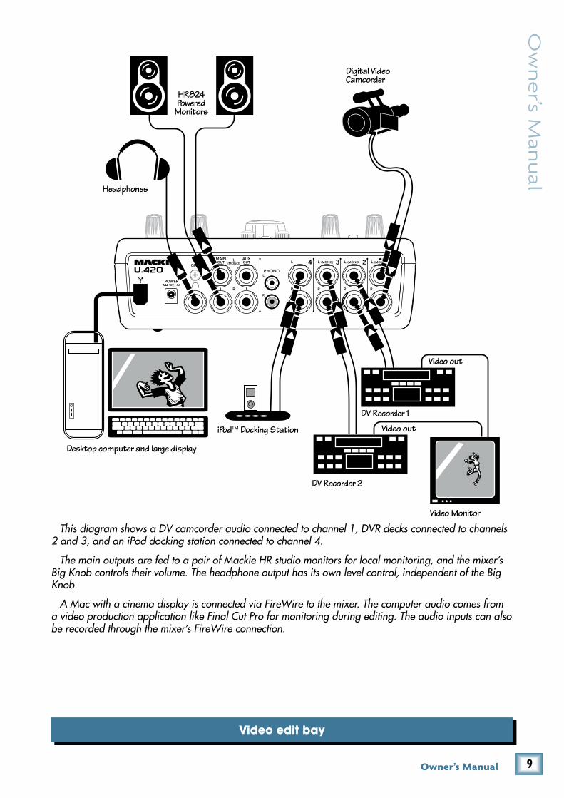
This diagram shows a DV camcorder audio connected to channel 1, DVR decks connected to channels 2 and 3, and an iPod docking station connected to channel 4.
The main outputs are fed to a pair of Mackie HR studio monitors for local monitoring, and the mixer’s Big Knob controls their volume. The headphone output has its own level control, independent of the Big Knob.
A Mac with a cinema display is connected via FireWire to the mixer. The computer audio comes from a video production application like Final Cut Pro for monitoring during editing. The audio inputs can also be recorded through the mixer’s FireWire connection.

10 U.4�0 4-Channel Line Mixer
U.4
20
4-C
han
ne
l Lin
e M
ixe
r RearPanelFeatures
1. INSTRUMENT/LINE Input
These inputs accept either 1/4" TRS balanced or TS unbalanced connectors.
Unlike the other inputs, channel 1’s left input can accept direct instrument-level signals such as from guitars, without the need for a DI box. For this to work, press channel 1’s instrument switch [11]. The guitar or other instrument will appear on both left and right of channel 1. (The right input is disconnected internally.)
If the instrument switch is out, then these inputs are just like the other channel line-level inputs described below.
�. LINE Inputs
These line-level inputs accept either 1/4" TRS bal-anced or TS unbalanced connectors.
You can connect stereo line-level sources such as CD players, MP3 players, keyboards, drum machines, tape players, and all manner of line-level goodies. You might need to purchase some RCA to 1/4" mono adapters, de-pending upon your source component. These are readily available at your local music, electronics, or grain and feed store.
These are stereo inputs; the left signals appear on the left main mix bus, and the right signals appear on the right main mix bus.
If you have a mono source component, then connect it to the left input, and the mono source will appear equally on the left and right of the main mix. (This does not apply to channel 4.)
�. PHONO Inputs
Channel 4’s RCA jacks accept stereo phono-level signals from turntables. Check that your turntable has a phono-level output and a moving-magnet cartridge. Turntables usually have a ground wire that needs to be connected to the ground terminal [4].
The turntable’s stereo phono-level signals are re-equalized and converted to line-level signals by the fine RIAA preamplifiers inside the mixer.
The phono inputs are internally disconnected if anything is plugged into channel 4’s line inputs.
Do not connect line-level sources to these phono-level inputs, or the phono preamplifiers may be overloaded. Use the line-level inputs
[2] instead.
4. GND Terminal
This terminal is provided to connect a ground wire from your turntable to the mixer. Most turntables pro-vide a ground wire for the purpose of eliminating hum in the audio signals.
Rotate this terminal counter-clockwise to loosen it, wrap the end of the ground wire clockwise around the terminal, and hand-tighten the terminal for a secure ground connection.
5. AUX Outputs
These 1/4" TRS jacks provide a balanced line-level output signal from the stereo aux bus. Use these to connect to the inputs of an external effects processor, another PA system, or stage monitors. You can also use unbalanced 1/4" TS connectors.
GND
PHONO
R
1234
R
L
POWER18V,1.5A
OUTMAIN
OUTAUX
(MONO)
R
L(MONO)L
R
L (MONO)L (MONO)L
R R
11Owner’s Manual
Ow
ne
r’s Man
ual
If you plug a cable into the left aux output jack, and leave the right output jack empty, the right and left signals are summed together
to provide a mono output.
The stereo aux output from these connectors is the sum of all channels whose aux level controls [16] are set to more than minimum. The aux bus gives you the chance to make a second mix or send an individual channel from the mixer, independent of the main level control [23] or channel level controls [17].
You could use the aux output to feed stage monitors, or to feed a headphone amplifier so you can wear head-phones on stage. This lets you get a different mix than the audience is hearing, plus you get to look a lot cooler and surprisingly attractive with headphones on.
If you are going out to an external processor, you can return its processed output to one of the mixer’s line-level input channels.
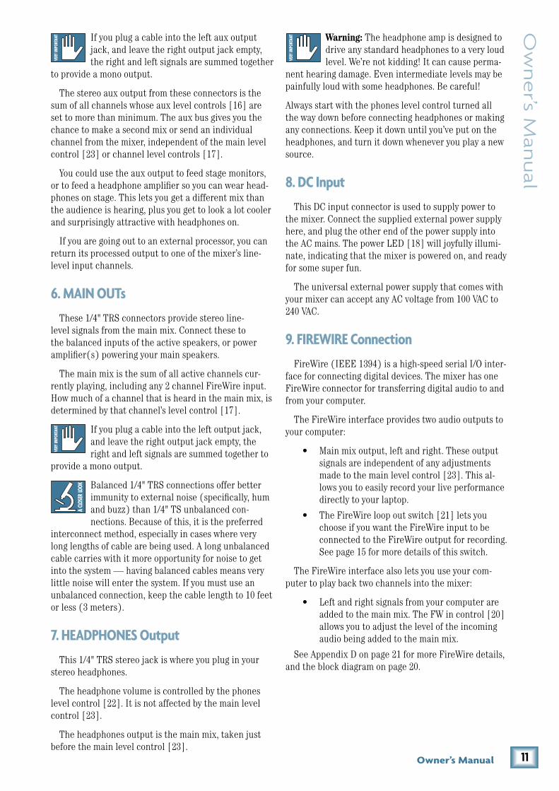
�. MAIN OUTs
These 1/4" TRS connectors provide stereo line-level signals from the main mix. Connect these to the balanced inputs of the active speakers, or power amplifier(s) powering your main speakers.
The main mix is the sum of all active channels cur-rently playing, including any 2 channel FireWire input. How much of a channel that is heard in the main mix, is determined by that channel’s level control [17].
If you plug a cable into the left output jack, and leave the right output jack empty, the right and left signals are summed together to
provide a mono output.
Balanced 1/4" TRS connections offer better immunity to external noise (specifically, hum and buzz) than 1/4" TS unbalanced con-nections. Because of this, it is the preferred
interconnect method, especially in cases where very long lengths of cable are being used. A long unbalanced cable carries with it more opportunity for noise to get into the system — having balanced cables means very little noise will enter the system. If you must use an unbalanced connection, keep the cable length to 10 feet or less (3 meters).
7. HEADPHONES Output
This 1/4" TRS stereo jack is where you plug in your stereo headphones.
The headphone volume is controlled by the phones level control [22]. It is not affected by the main level control [23].
The headphones output is the main mix, taken just before the main level control [23].
Warning: The headphone amp is designed to drive any standard headphones to a very loud level. We’re not kidding! It can cause perma-
nent hearing damage. Even intermediate levels may be painfully loud with some headphones. Be careful!
Always start with the phones level control turned all the way down before connecting headphones or making any connections. Keep it down until you’ve put on the headphones, and turn it down whenever you play a new source.
8. DC Input
This DC input connector is used to supply power to the mixer. Connect the supplied external power supply here, and plug the other end of the power supply into the AC mains. The power LED [18] will joyfully illumi-nate, indicating that the mixer is powered on, and ready for some super fun.
The universal external power supply that comes with your mixer can accept any AC voltage from 100 VAC to 240 VAC.
9. FIREWIRE Connection
FireWire (IEEE 1394) is a high-speed serial I/O inter-face for connecting digital devices. The mixer has one FireWire connector for transferring digital audio to and from your computer.
The FireWire interface provides two audio outputs to your computer:
• Main mix output, left and right. These output signals are independent of any adjustments made to the main level control [23]. This al-lows you to easily record your live performance directly to your laptop.
• The FireWire loop out switch [21] lets you choose if you want the FireWire input to be connected to the FireWire output for recording. See page 15 for more details of this switch.
The FireWire interface also lets you use your com-puter to play back two channels into the mixer:
• Left and right signals from your computer are added to the main mix. The FW in control [20] allows you to adjust the level of the incoming audio being added to the main mix.
See Appendix D on page 21 for more FireWire details, and the block diagram on page 20.

1� U.4�0 4-Channel Line Mixer
U.4
20
4-C
han
ne
l Lin
e M
ixe
r TopPanelFeatures
ChannelControls10. LEVEL SET LED
These LEDs are used with the gain control [12] to set the level of the channel’s preamplifier gain just right. They light when the signal level is 0 dBu.
Adjust the gain control so these LEDs come on while you are playing, and go off when you stop. As a rough guide, adjust the gain until the LEDs are on for about half the time during your performance.
Setting the gain correctly will ensure that the pre-amplifier’s gain is not too high, where distortion could occur, and not too low, where your quieter, exquisitely-delicate passages might be lost in background noise.
11. INSTRUMENT SWITCH
When this switch is pressed in, channel 1’s left input can accept direct instrument-level signals from guitars or other instruments. They will be impedance-matched to the channel 1 left input, without the need for a DI box. (The right input is disconnected.)
When this switch is out, input 1 is a line-level input, just like inputs 2–4. You can connect stereo line-level sources such as CD players, MP3 players, keyboards, drum machines, and tape players. You will need a DI box if connecting instrument-level signals to the inputs when this switch is out.
1�. GAIN
These knobs allow you to adjust the gain of each channel’s stereo preamplifier.
Signals from the line-level input jacks go straight to the preamplifiers. Phono-level signals entering the phono inputs [3] of channel 4 are first passed through an RIAA phono preamplifier to become line-level signals.
The gain ranges from –14 dB to +14 dB, and the center U position represents unity, or zero gain. Adjust the gain so the level set LEDs [10] come on while you are playing, and go off when you stop. As a rough guide, adjust the gain until the LED is on for about half the time during your performance. Listen for any distortion at the higher levels.
Adjust the gain after plugging in any input, or playing a new source or instrument for the first time.
OO MAX
+14-14 +14-14 +14-14 +14-14
MID
LOW
HIGH
EQ
GAIN
LEVEL
U U
U U
U U
U
U
U
OO MAX
1 2 3 4
U
OO MAX
LEVELU
OO MAX
U
U
MID
LOW
HIGH
EQ
GAIN
+10KILL
U
+10KILL
U U
U
+10KILL
U
+10KILL
U
+10KILL
U
+10KILL
+10KILL +10KILL
+10KILL +10KILL
+10KILL +10KILL
LEVELSET
LEVELSET
AUX
OO MAX OO MAX
AUX
OO MAX OO MAX
OL
10
7
4
0
4
10
20
POWER
L R
MAXFW IN
MAXOO
OO MAXPHONESOO
LOOPOUT
1�Owner’s Manual
Ow
ne
r’s Man
ual
�-BAND EQ
The U.420 has 3-band equalization at carefully selected points — low shelving at 300 Hz, mid peaking at 1 kHz, and high shelving at 4 kHz. “Shelving” means that the circuitry boosts or cuts all frequencies past the specified frequency. For example, rotating the low EQ knob clockwise will boost the bass at 300 Hz and below. “Peaking” means that certain frequencies form a “hill” around the center frequency — 1 kHz in the case of the mid EQ.
Be careful with the EQ, or you can really upset things. We’ve designed a lot of boost and cut into each equalizer circuit, because we know everyone will occasionally need that. But if
you max the EQs on every channel, you’ll get mix mush. Equalize subtly and use the left sides of the knobs (cut), as well as the right (boost). You can create many interesting and useful EQ changes by turning the knobs down and adjusting the level [17] up if needed.
If all the EQ controls in a channel are turned down to the kill position, then that channel is effectively muted. (Word: DJs find it very useful to have EQ controls with a kill position, in their fast-paced beat-based world.)
1�. HIGH EQ
This gives up to 10 dB of boost for the frequency range above 4 kHz, and the highs are muted in the kill posi-tion. In the center position U, high EQ has no effect.
Use it to add sizzle to cymbals, and an overall sense of transparency, or edge to keyboards, vocals, guitar and bacon frying. Turn it down a little to reduce sibilance, or to hide tape hiss.
14. MID EQ
This gives up to 10 dB of boost for frequencies cen-tered around 1 kHz, and the mid range is muted in the kill position. In the center position U, mid EQ has no effect.
Midrange EQ is often thought of as the most dynamic, because the frequencies that define any particular sound are almost always found in this range.
15. LOW EQ
This gives up to 10 dB of boost for the frequency range below 300 Hz, and the lows are muted in the kill posi-tion. In the center position U, low EQ has no effect.
The frequency range below 300 Hz represents the realm of bass drums, bass guitar, fat synth patches, and lower down to some really serious male singers.
1�. AUX
These stereo controls allow you to adjust how much of the channel signal is added to the aux bus. The aux bus contains the sum of all channels whose aux controls are set to more than minimum.
The aux bus feeds the aux outputs [5], typically out to an external processor. Each channel’s stereo signal retains it’s stereo image as it is sent to the aux bus. This is great for keyboard players who work with stereo sounds from stereo effects processors.
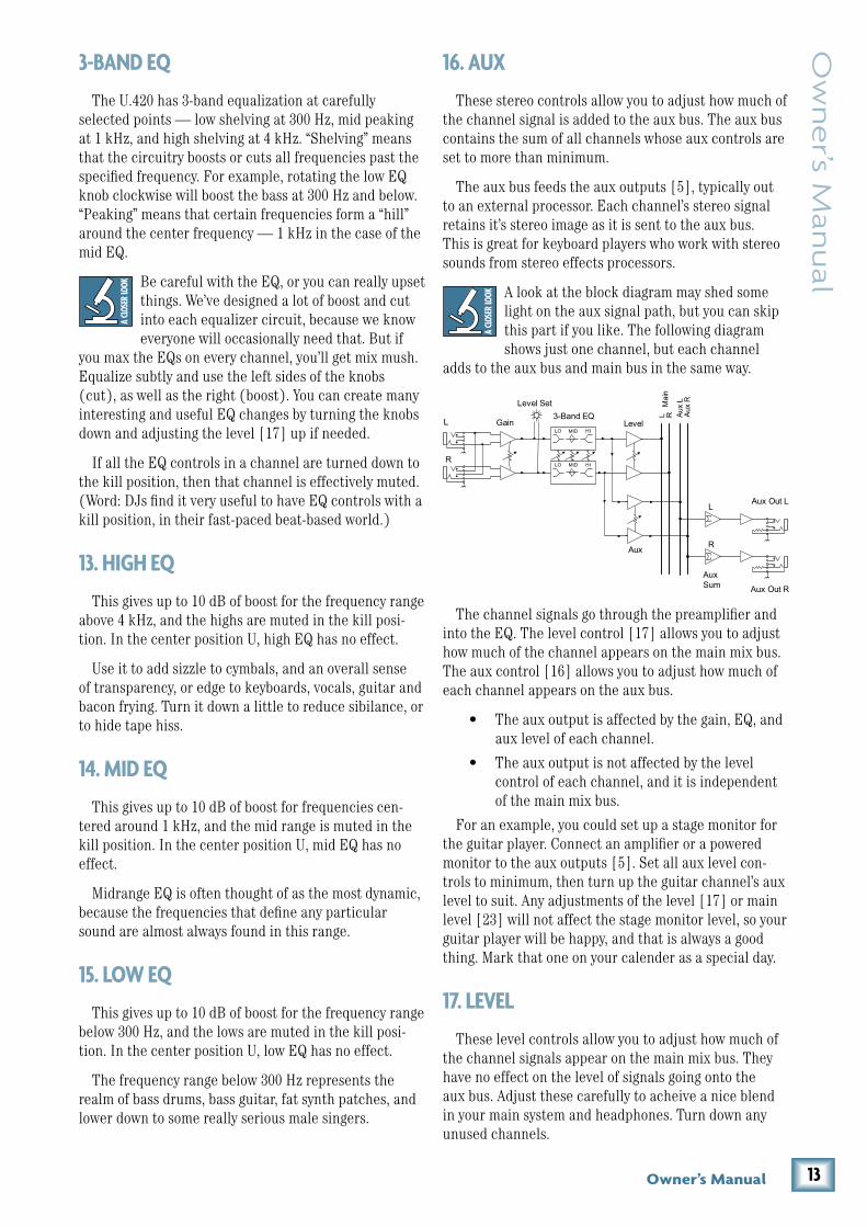
A look at the block diagram may shed some light on the aux signal path, but you can skip this part if you like. The following diagram shows just one channel, but each channel
adds to the aux bus and main bus in the same way.
The channel signals go through the preamplifier and into the EQ. The level control [17] allows you to adjust how much of the channel appears on the main mix bus. The aux control [16] allows you to adjust how much of each channel appears on the aux bus.
• The aux output is affected by the gain, EQ, and aux level of each channel.
• The aux output is not affected by the level control of each channel, and it is independent of the main mix bus.
For an example, you could set up a stage monitor for the guitar player. Connect an amplifier or a powered monitor to the aux outputs [5]. Set all aux level con-trols to minimum, then turn up the guitar channel’s aux level to suit. Any adjustments of the level [17] or main level [23] will not affect the stage monitor level, so your guitar player will be happy, and that is always a good thing. Mark that one on your calender as a special day.
17. LEVEL
These level controls allow you to adjust how much of the channel signals appear on the main mix bus. They have no effect on the level of signals going onto the aux bus. Adjust these carefully to acheive a nice blend in your main system and headphones. Turn down any unused channels.
L RM
ain
Level
Aux Out L
Aux
L
L
R
3-Band EQGain
LO HIMID
LO HIMID
Aux Out R
Aux
R
Aux
Level Set
AuxSum
L
R

14 U.4�0 4-Channel Line Mixer
U.4
20
4-C
han
ne
l Lin
e M
ixe
r
ControlSection18. POWER LED
This will light whenever the external power supply is connected to the mixer and to a live AC mains supply. The mixer does not have a power switch, so as long as the external power supply is connected and operating, this LED should be on.
19. METERS
These meters have 8 LEDs each, ranging from –20 to +13.5 (OL). They indicate the stereo signal strength of the main mix after the main level control [23].
Typically, you want to see these meters bouncing between the “0” and the “+4” LEDs. It is okay if the OL LEDs light occasionally, but if they light frequently or continuously, turn down the main level control until they blink occasionally or not at all.
�0. FW IN
This control lets you adjust the signal level of the two FireWire channels coming in from your computer, rela-tive to the mix of channels 1 to 4. Adjust it carefully to achieve the desired mix with the other channels. (If the other level controls [17] are down, then the meters will show the level of the FireWire input only.)
The FireWire input from your audio software such as Tracktion, could be individual instrument tracks, a mix of tracks, or processed tracks.
OO MAX
+14-14 +14-14 +14-14 +14-14
MID
LOW
HIGH
EQ
GAIN
LEVEL
U U
U U
U U
U
U
U
OO MAX
1 2 3 4
U
OO MAX
LEVELU
OO MAX
U
U
MID
LOW
HIGH
EQ
GAIN
+10KILL
U
+10KILL
U U
U
+10KILL
U
+10KILL
U
+10KILL
U
+10KILL
+10KILL +10KILL
+10KILL +10KILL
+10KILL +10KILL
LEVELSET
LEVELSET
AUX
OO MAX OO MAX
AUX
OO MAX OO MAX
OL
10
7
4
0
4
10
20
POWER
L R
MAXFW IN
MAXOO
OO MAXPHONESOO
LOOPOUT
15Owner’s Manual
Ow
ne
r’s Man
ual
�1. FW LOOP OUT
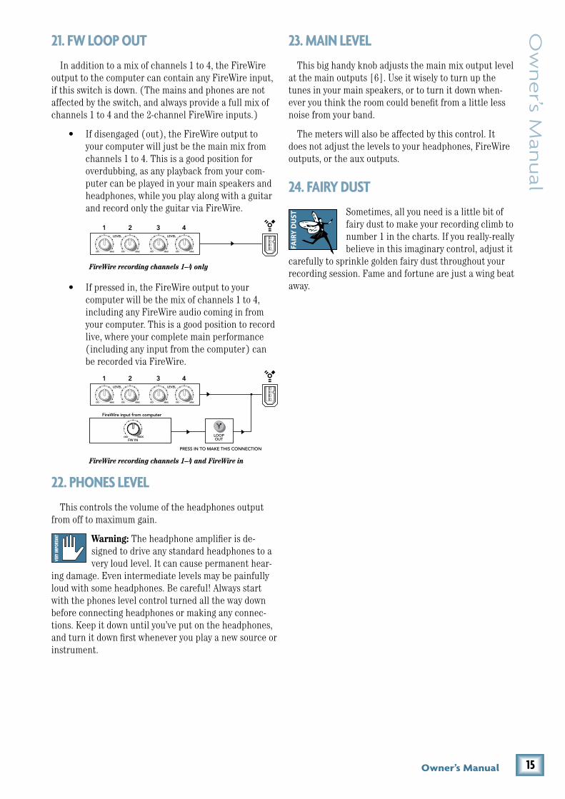
In addition to a mix of channels 1 to 4, the FireWire output to the computer can contain any FireWire input, if this switch is down. (The mains and phones are not affected by the switch, and always provide a full mix of channels 1 to 4 and the 2-channel FireWire inputs.)
• If disengaged (out), the FireWire output to your computer will just be the main mix from channels 1 to 4. This is a good position for overdubbing, as any playback from your com-puter can be played in your main speakers and headphones, while you play along with a guitar and record only the guitar via FireWire.
• If pressed in, the FireWire output to your computer will be the mix of channels 1 to 4, including any FireWire audio coming in from your computer. This is a good position to record live, where your complete main performance (including any input from the computer) can be recorded via FireWire.
��. PHONES LEVEL
This controls the volume of the headphones output from off to maximum gain.
Warning: The headphone amplifier is de-signed to drive any standard headphones to a very loud level. It can cause permanent hear-
ing damage. Even intermediate levels may be painfully loud with some headphones. Be careful! Always start with the phones level control turned all the way down before connecting headphones or making any connec-tions. Keep it down until you’ve put on the headphones, and turn it down first whenever you play a new source or instrument.
��. MAIN LEVEL
This big handy knob adjusts the main mix output level at the main outputs [6]. Use it wisely to turn up the tunes in your main speakers, or to turn it down when-ever you think the room could benefit from a little less noise from your band.
The meters will also be affected by this control. It does not adjust the levels to your headphones, FireWire outputs, or the aux outputs.
�4. FAIRY DUST
Sometimes, all you need is a little bit of fairy dust to make your recording climb to number 1 in the charts. If you really-really believe in this imaginary control, adjust it
carefully to sprinkle golden fairy dust throughout your recording session. Fame and fortune are just a wing beat away.
FAIR
Y D
UST
OO MAX
LEVELU
OO MAX
U
OO MAX
LEVELU
OO MAX
U
1 2
FireWire input from computer
3 4
MAXFW IN
OO LOOPOUT
PRESS IN TO MAKE THIS CONNECTION
FireWire recording channels 1–4 and FireWire in
FireWire recording channels 1–4 only
OO MAX
LEVELU
OO MAX
U
OO MAX
LEVELU
OO MAX
U
1 2 3 4
OO MAX
LEVELU
OO MAX
U
OO MAX
LEVELU
OO MAX
U
1 2
FireWire input from computer
3 4
MAXFW IN
OO LOOPOUT
PRESS IN TO MAKE THIS CONNECTION
FireWire recording channels 1–4 and FireWire in
FireWire recording channels 1–4 only
OO MAX
LEVELU
OO MAX
U
OO MAX
LEVELU
OO MAX
U
1 2 3 4
1� U.4�0 4-Channel Line Mixer
U.4
20
4-C
han
ne
l Lin
e M
ixe
r AppendixA:ServiceInformation• If you are playing a guitar into channel 2, 3, or 4,
you need to use a DI box for the correct impedance match and high frequency fidelity.
• Try the same source signal in another channel, set up exactly like the suspect channel.
• Only phono-level sources (turntables) should be connected to the RCA phono inputs [3]. The phono section requires your cartridge to be a moving-mag-net type. It may be too low to amplify the low levels of a moving-coil type.
• If there is no phono output, check that there is nothing plugged into channel 4’s line inputs. The phono inputs are internally disconnected if any-thing is plugged into channel 4’s line inputs.
• Only line-level sources should be connected to the line-level inputs [2] of channels 2, 3, and 4.
• If possible, listen to the signal with headphones plugged into the input source device. If it sounds bad there, it’s not the mixer causing the problem.
Bad Output
• Is the associated level control (if any) turned up?
• If a left output is presumed dead, switch the left and right cords at the mixer end. If the problem stays on the left side, it’s not the mixer. but maybe your left speaker, left speaker cables, or left ampli-fier channel.
Noise/Hum
• Check that your turntable’s audio ground wire is connected to the ground terminals [4].
• Turn down each channel, one by one. If the noise disappears, it’s coming from whatever is plugged into that channel. Check your whatever.
• Check the signal cables between the input sources and the mixer. Disconnect them one by one. When the noise goes away, you’ll know which input source is causing the problem.
• It helps to plug all the audio equipment into the same AC circuit so they share a common ground.
• If the annoying humming continues, ask the drum-mer to leave the room, or at least have him learn the words.
If you think your U.420 has a problem, please check out the following troubleshooting tips and do your best to confirm the problem. Visit the Support section of our website (www.mackie.com/support) where you will find lots of useful information such as FAQs, documentation, and user forums. You may find the answer to the prob-lem without having to send your U.420 away.
TroubleshootingNo Power
• Make sure the external power supply is securely seated in the DC input [8] and plugged all the way into the AC outlet.
• Make sure the AC outlet is live (check with a tester or lamp).
• Is the power LED [18] illuminated? If not, make sure the AC outlet is live.
• Are all the lights out in your town? If so, contact your local power company to get power restored.
• If no LEDs are illuminated, and you are certain that the external power supply is working, it will be necessary to have your mixer serviced. There are no user serviceable parts inside. Refer to “Repair” on the next page to find out how to proceed.
Bad Channel
• Check the connections from your source are made securely, and that the cords are in good condition.
• Check the channel’s program gain controls [12] are set correctly.
• Are that channel’s EQ controls all turned down to the kill position perchance?
• Is the signal source turned up? Make sure the signal level from the selected input source is high enough to light the level set LEDs [10] when ad-justed with the gain controls.
• If you are playing a guitar or other instrument level source into channel 1, make sure the instrument switch [11] is engaged.

17Owner’s Manual
Ow
ne
r’s Man
ual
RepairFor warranty repair or replacement, refer to the war-
ranty information on page 27.
Non-warranty repair for Mackie products is available at a factory-authorized service center. To locate your nearest service center, visit www.mackie.com, click “Support” and select “Locate a Service Center.” Service for Mackie products living outside the United States can be obtained through local dealers or distributors.
If you do not have access to our website, you can call our Tech Support department at 1-800-898-3211, Monday-Friday, 7 am to 5 pm Pacific Time, to explain the problem. Tech Support will tell you where the nearest factory-authorized service center is located in your area.

18 U.4�0 4-Channel Line Mixer
U.4
20
4-C
han
ne
l Lin
e M
ixe
r
1/4"TRSPhonePlugsandJacks“TRS” stands for Tip-Ring-Sleeve, the three connection points available on a stereo 1/4" or balanced phone jack or plug. TRS jacks and plugs are used for balanced signals and stereo headphones:
Balanced Mono
SLEEVE
TIPSLEEVE
TIP
RING
RING
TIP
SLEEVERING
1/4" TRS Balanced Mono Wiring:Sleeve = Shield Tip = Hot (+) Ring = Cold (–)
Stereo Headphones
SLEEVE
TIPSLEEVE
TIP
RING
RING
TIP
SLEEVERING
1/4" TRS Stereo Unbalanced Wiring:Sleeve = Shield Tip = Left Ring = Right
1/4"TSPhonePlugsandJacks“TS” stands for Tip-Sleeve, the two connection points available on a mono 1/4" phone jack or plug. They are used for unbalanced signals.
SLEEVE
TIP
TIPSLEEVE
TIP
SLEEVE
1/4" TS Unbalanced Wiring:Sleeve = Shield Tip = Hot (+)
AppendixB:ConnectionsRCAPlugsandJacksRCA-type plugs (also known as phono plugs) and jacks are often used in home stereo and video equipment and in many other applications. They are unbalanced and electrically equivalent to a 1/4" TS phone plug.
TIPSLEEVETIPSLEEVE
RCA Unbalanced Wiring:Sleeve = Shield Tip = Hot (+)
8.6 in/218 mm
8.8 in/224 mm
3.4 in/87 mm
WEIGHT2.5 lb 1.13 kg
Dimensions

19Owner’s Manual
Ow
ne
r’s Man
ual
AppendixC:TechnicalInfo
Input Impedance: Line input: 100 kΩ balanced
Phono input: 47.5 kΩ shunt with 200 pF
Maximum Output Levels: Main out: +15 dBu
Aux out: +15 dBu
Phones: 1.5 Vrms into 32 Ω (70 mW)
Output Impedance: Main out: 120 Ω
Aux out: 120 Ω
Phones: 50 Ω
Equalization Low: +10/–inf dB @ 300 Hz
Mid: +10/–inf dB @ 1 kHz
High: +10/–inf dB @ 4 kHz
FireWire Sample rates: 44.1 kHz, 48 kHz, 88.2 kHz, 96 kHz
Resolution: 24-bit
VU Meters 8–segment post main level meters
OL (+13), +10, +7, +4, +0, –4, –10, –20 dBu
Level set LED (sensitivity): 0 dBu
AC Power Requirements: Power consumption: 8.3 watts
Universal AC power supply: 100–240 VAC, 50–60 Hz
Physical Dimensions and Weight:Height: 8.6 in/218 mm
Width: 8.8 in/224 mm
Depth: 3.4 in/87 mm
Weight: 2.5 lb/1.13 kg
LOUD Technologies Inc. is always boldly striving to improve our products by incorporating new and improved materi-als, components, and manufacturing methods. Therefore, we reserve the right to change these specifications at any time without notice.
“Mackie,” and the “Running Man” are registered trademarks of LOUD Technologies Inc. All other brand names mentioned are trademarks or registered trademarks of their respective hold-ers, and are hereby acknowledged.
©2007-2008 LOUD Technologies Inc. All Rights Reserved.
SpecificationsFrequency Response (�0 Hz to �0 kHz, unity gain) : Line input to any output: +0/–0.5 dB
Phono input to any output: ±0.5 dB of RIAA EQ curve
FireWire output to FireWire input (with loop out switch engaged): +0/–0.5 dB
Distortion (THD+N): Main and aux output, 20 Hz to 20 kHz, 1 kHz input signal:
Line input at unity gain, 4 dBu input signal: Better than 0.008%
Phono input at unity gain, –30 dBu input signal: Better than 0.030%
FireWire output to FireWire input : Better than 0.005%
Phones output, 20 Hz to 20 kHz, +4 dBu input signal: Line input at unity gain: Better than 0.004%
Attenuation/Crosstalk:Main level at unity gain, 1 kHz input signal placed on any chan-nel with gain knob at unity and level knob at minimum, main outs (20 Hz–20 kHz): Better than –85 dBu
Main level at unity gain, 1 kHz input signal placed on any chan-nel with gain knob at unity and level knob at minimum, main outs measured (20 Hz to 20 kHz) with any other channel gain knob at unity and level knob at unity: Better than –85 dBu
Noise Characteristics: Signal to Noise Ratio, 20 Hz to 20 kHz, ref +4 dBu:
Main out at unity, all channel gain knobs at minimum: Better than –91 dB
Main out at unity, all channel gain knobs at unity (dummy plugs in channel 4 TRS inputs so phono is disengaged): Better than –86 dB
Main out at unity, channels 1 – 3 at minimum, channel 4 phono at unity gain (no TRS plugs in channel 4): Better than –74 dB
All channel aux knobs at unity and all channel gain knobs at unity: Better than –89 dB
Main out at unity, all channel gain knobs at minimum, FireWire input level at unity: Better than –87 dB
Maximum Input Levels (rated at 1% THD):Line inputs, unity gain: +15 dBu
Phono input: 77 mV rms @ 1kHz
Input/Output Characteristics: Input gain control range:
Line input gain knob: –14 to +14 dB
Line input level knob: Off to +10 dB
Output gain control range:
Main level knob: Off to +10 dB
Channel aux knob: Off to +10 dB

�0 U.4�0 4-Channel Line Mixer
U.4
20
4-C
han
ne
l Lin
e M
ixe
r
Bloc
kDi
agra
m
L
RMain
L
R Main
Mai
n O
utle
vel
Leve
l
Aux
Out
L
L R
Aux L
Mai
n O
ut L
Ph
ones
leve
l
NO
TE
: Sw
itche
s ar
e sh
own
in th
e de
faul
t (ou
t) p
ositi
on.
Cha
nnel
s 2-
3
L R
3-B
and
EQ
Gai
n
Gai
n
LOH
IM
ID
LOH
IM
ID
Mai
n O
ut R
Aux
Out
R
Pho
nes
Cha
nnel
4
Aux R
Aux
Leve
l
L R
3-B
and
EQ
Gai
n
LOH
IM
ID
LOH
IM
ID
Aux
L
Pho
no
R
Leve
l
Cha
nnel
1
L R
3-B
and
EQ
LO
HI–
Z
HI
MID
LOH
IM
ID
Aux
HI-
ZN
orm
al
Fire
Wire
Infr
om C
omp
uter
Fir
ewir
eIn
Lev
el
Fire
wire
Sum
Leve
l Set
Aux L
Aux R
Leve
l Set
RIA
A p
ream
p
Ch.
1-4
to F
W o
utpu
t
Fire
Wire
inpu
t a
nd
Ch
.1-4
to F
W o
utpu
t
L R
Mai
n M
ixS
umC
hann
el
Aux
Sum
Sum
L R
L R
Fire
Wire
Out
to C
ompu
ter
Mai
n O
ut
Lev
el
Leve
l Set
DA
CA
DC
L R
�1Owner’s Manual
Ow
ne
r’s Man
ual
AppendixD:FireWireSystem Requirements
These are the minimum requirements for your com-puter system to use the U.420 FireWire interface.
For the PC:
• Windows XP (service pack 2)
• Pentium 4 or Athlon XP processor
• 256 MB RAM
For the Mac:
• OS X (10.3.9 or higher)
• G4 processor
• 256 MB RAM
The internal FireWire interface will allow the left and right main mix to be recorded on a Mac or PC computer. It also allows two channels of audio to be added to the main mix from the computer.
FireWire stream from computer
The following table shows the outputs from your com-puter to the mixer’s FireWire interface:
The 2-channel digital stream from the computer enters the mixer through the FireWire connector and is converted to analog audio.
The audio level can be adjusted using the FW in control [20].
Beware of a possible feedback loop, if you are feeding the main mix back into the mixer.
FireWire stream to computer
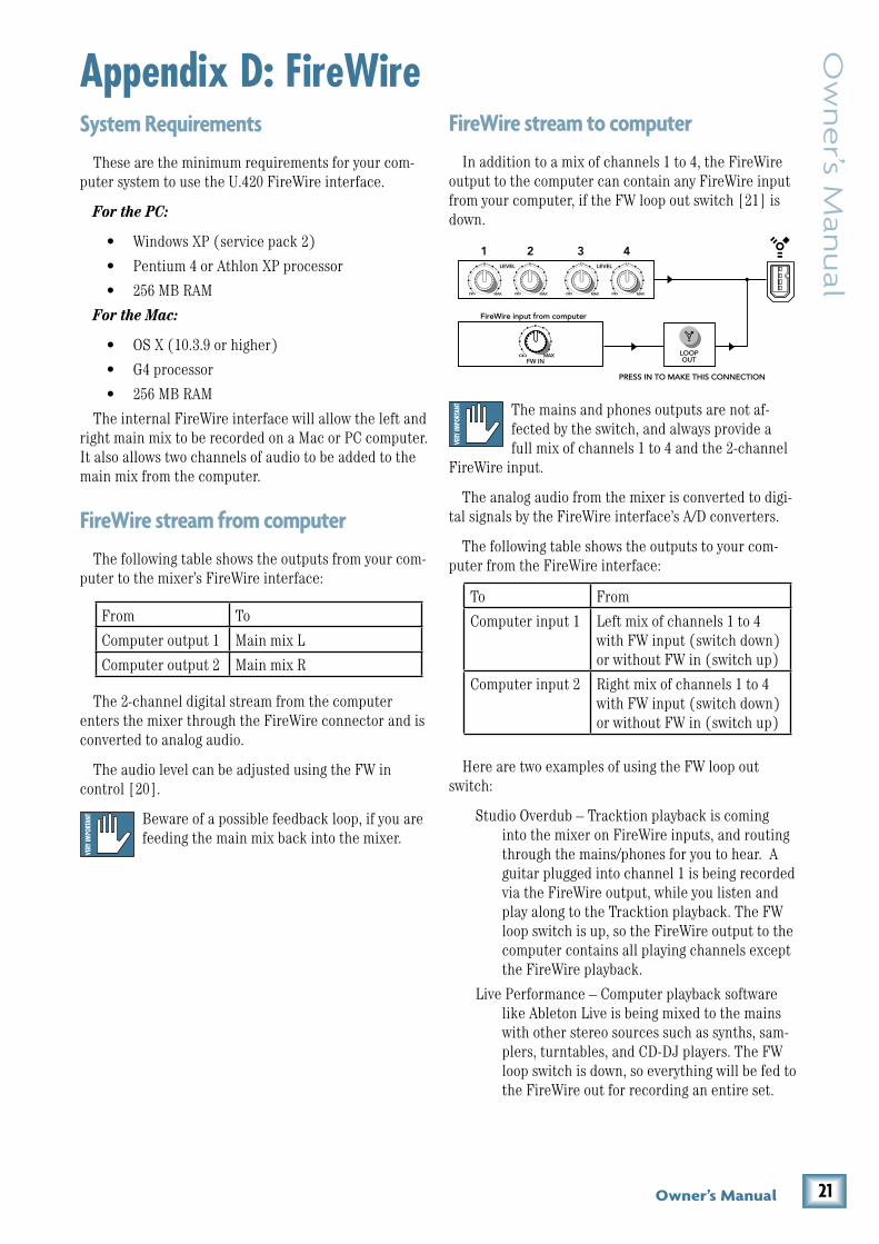
In addition to a mix of channels 1 to 4, the FireWire output to the computer can contain any FireWire input from your computer, if the FW loop out switch [21] is down.
The mains and phones outputs are not af-fected by the switch, and always provide a full mix of channels 1 to 4 and the 2-channel
FireWire input.
The analog audio from the mixer is converted to digi-tal signals by the FireWire interface’s A/D converters.
The following table shows the outputs to your com-puter from the FireWire interface:
Here are two examples of using the FW loop out switch:
Studio Overdub – Tracktion playback is coming into the mixer on FireWire inputs, and routing through the mains/phones for you to hear. A guitar plugged into channel 1 is being recorded via the FireWire output, while you listen and play along to the Tracktion playback. The FW loop switch is up, so the FireWire output to the computer contains all playing channels except the FireWire playback.
Live Performance – Computer playback software like Ableton Live is being mixed to the mains with other stereo sources such as synths, sam-plers, turntables, and CD-DJ players. The FW loop switch is down, so everything will be fed to the FireWire out for recording an entire set.
To From
Computer input 1 Left mix of channels 1 to 4 with FW input (switch down) or without FW in (switch up)
Computer input 2 Right mix of channels 1 to 4 with FW input (switch down) or without FW in (switch up)
From To
Computer output 1 Main mix L
Computer output 2 Main mix R
OO MAX
LEVELU
OO MAX
U
OO MAX
LEVELU
OO MAX
U
1 2
FireWire input from computer
3 4
MAXFW IN
OO LOOPOUT
PRESS IN TO MAKE THIS CONNECTION
FireWire recording channels 1–4 and FireWire in
FireWire recording channels 1–4 only
OO MAX
LEVELU
OO MAX
U
OO MAX
LEVELU
OO MAX
U
1 2 3 4
�� U.4�0 4-Channel Line Mixer
U.4
20
4-C
han
ne
l Lin
e M
ixe
r
The U.420’s built in FireWire connection allows over-dub style recording to a Mac or PC digital audio work-station (DAW) through the FireWire cable.
Here are some steps showing how to record a first track, and then record additional tracks while monitor-ing ones that have already been recorded.
1. Connect the sound source you wish to record to your audio software, for example:
• A line-level source such as an electronic keyboard.
• A turntable connected to the phono inputs.
• An instrument connected directly to the instrument input 1 (with the instrument switch [11] pressed in).
2. Make sure the FW loop switch [21] is not pressed in. This will ensure that during each recording pass, the audio software only receives the track-in-progress as an audio signal, and not the pre-existing mix from the computer as well.
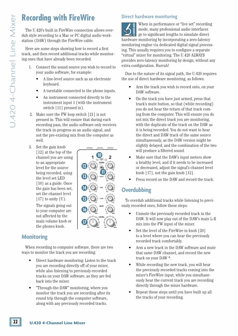
3. Set the gain knob [12] at the top of the channel you are using to an appropriate level for the source being recorded, using the level set LED [10] as a guide. Once the gain has been set, set the channel level [17] to unity (U).
The signals going out to your computer are not affected by the main volume knob or the phones knob.
Monitoring
When recording to computer software, there are two ways to monitor the track you are recording:
• Direct hardware monitoring: Listen to the track you are recording directly off of your mixer, while also listening to previously-recorded tracks on your DAW software, as they are fed back into the mixer.
• ”Through-the-DAW” monitoring, where you monitor the track you are recording after its round trip through the computer software, along with any previously recorded tracks.
Direct hardware monitoringWhen in performance or “live set” recording mode, many professional audio interfaces go to significant lengths to simulate direct
hardware monitoring by incorporating a zero-latency monitoring engine via dedicated digital signal process-ing. This usually requires you to configure a separate “virtual” mixer for monitoring. The U.420 ALWAYS provides zero-latency monitoring by design, without any extra configuration. Hurrah!
Due to the nature of its signal path, the U.420 requires the use of direct hardware monitoring, as follows:
• Arm the track you wish to record onto, on your DAW software.
• On the track you have just armed, press that track’s mute button, so that (while recording) you do not hear the return of that track com-ing from the computer. This will ensure you do not mix the direct track you are monitoring, with the duplicate of the track on the DAW as it is being recorded. You do not want to hear the direct and DAW track of the same source simultaneously, as the DAW version might be slightly delayed, and the combination of the two will produce a filtered sound.
• Make sure that the DAW’s input meters show a healthy level, and if it needs to be increased or decreased, adjust the signal’s channel level knob [17], not the gain knob [12].
• Press record on the DAW and record the track.
Overdubbing
To overdub additional tracks while listening to previ-ously recorded ones, follow these steps:
• Unmute the previously recorded track in the DAW. It will now play out of the DAW’s main L-R mix into the FW input of the mixer.
• Set the level of the FireWire in knob [20] to a level where you can hear the previously recorded track comfortably.
• Arm a new track in the DAW software and mute that same DAW channel, and record the new track on your DAW *.
• While recording the new track, you will hear the previously recorded tracks coming into the mixer’s FireWire input, while you simultane-ously hear the current track you are recording directly through the mixer hardware.
• Repeat these steps until you have built up all the tracks of your recording.
RecordingwithFireWire
OO MAX
+14-14 +14-14 +14-14 +14-14
MID
LOW
HIGH
EQ
GAIN
LEVEL
U U
U U
U U
U
U
U
OO MAX
1 2 3 4
U
OO MAX
LEVELU
OO MAX
U
U
MID
LOW
HIGH
EQ
GAIN
+10KILL
U
+10KILL
U U
U
+10KILL
U
+10KILL
U
+10KILL
U
+10KILL
+10KILL +10KILL
+10KILL +10KILL
+10KILL +10KILL
LEVELSET
LEVELSET
AUX
OO MAX OO MAX
AUX
OO MAX OO MAX
OL
10
7
4
0
4
10
20
POWER
L R
MAXFW IN
MAXOO
OO MAXPHONESOO
LOOPOUT

��Owner’s Manual
Ow
ne
r’s Man
ual
* In Tracktion, it is not necessary to mute the output of the track you are overdubbing on. Instead, select the input to the track (it will be highlighted in red) and dis-able the end-to-end function.
You’ll hear existing tracks playing back via the FireWire in, and you’ll be monitoring the track you are recording through the U.420’s headphones or main out. When you play back the recording, you’ll hear the track you’ve just overdubbed without un-muting anything.
Other tips
• One drawback of using direct hardware moni-toring (vs. through-DAW monitoring) is that the track you are recording will not normally be able to take advantage of any effects that the DAW’s mixer has to offer, such as a reverb on the vocal being recorded, or a guitar amp simulation on a directly attached instrument. One workaround for this is the following:
• Set the latency on your DAW to as low as the computer can handle, and set the U.420 software console panel to the same value (see page 25 for more information on the console).
• Do not mute the channel on the DAW that is being recorded. This will allow you to hear a mixture of the direct hardware monitor, and the through-DAW signal.
• Apply the effect of choice (reverb, amp emulation) to the DAW track, which you will hear mixed in with the direct hardware monitor source.
• As long as the latency is set low enough, the timing difference between the direct and through-DAW signal should be small enough to not cause distraction.
A word about latency (wait-and-see)Latency describes the amount of time it takes the
input signal to pass through the system, and reach the output. When recording a guitar and monitoring through software, it is the amount of time it takes from the moment you strike your guitar string, to the moment you hear it in your headphones. You are used to this la-tency being very close to zero; when you play your guitar through a guitar amp, you hear the signal immediately. So when you are recording and monitoring via software, you want this latency to be very low.
We would like to set the latency as low as possible, but the smaller it is, the harder the computer will have to work. If the latency is very small, the computer needs to work very hard to quickly transfer the audio in and out. It may not even be able to keep up, especially if there are lots of tracks, lots of automation and/or lots of plug-ins in your work. If this happens, your audio may stop or “drop out.” Drop outs may also occur if you have a slower computer or not enough memory.
When recording using the overdub method, it is important to set the U.420’s latency to it’s lowest oper-able setting. This means going into the audio interface property page of your recording program and setting the latency property to the lowest setting the device and your system will accept without any drop-outs, distor-tion or CPU overburdening.
The buffer is an area of computer memory that your DAW uses to hold audio as it works. The smaller the buffer, the faster audio gets in and out of your com-puter, and the lower the latency. The size of the buffer is measured in samples. Depending on your system, a low setting is typically between 64 and 256 samples. The more samples, the higher the latency time value. This time value varies by sample rate, as shown in this table.
It is generally accepted that delay or latency times of 3.3 ms or less, are tolerable for musical timing accuracy.
Higher latency settings are fine and even necessary when in live record or performance mode. The same is true for mix-down mode, especially when you start add-ing lots of plug-ins.
Samples 44.1 kHz 48 kHz 96 kHz
64 1.5 ms 1.3 ms 0.7 ms
128 2.9 ms 2.7 ms 1.3 ms
256 5.8 ms 5.3 ms 2.7 ms

�4 U.4�0 4-Channel Line Mixer
U.4
20
4-C
han
ne
l Lin
e M
ixe
r SoftwareinstallationForthePC:
When using the mixer with a PC, it is necessary to first install the drivers and the control panel. The con-trol panel allows you to set the sample rate and adjust the latency (delay) of the audio passing through the mixer’s FireWire interface. Go to page 26 if you use a Mac.
Do not connect the mixer’s FireWire con-nector to your computer just yet. We’ll tell you when it’s time to do that.
To install the software on a PC running Windows XP (SP�):
1. Turn off any (non-essential) applications.
2. Insert the U.420 CD-ROM into your PC’s CD-ROM drive.
3. Click Start in the task bar, then click Run and click Browse. Browse to your CD drive and double-click _SETUP.EXE. Then click OK to start the installation.
4. The Installer opens. Click “Continue.”
5. Next you will see the License Agreement. Read through the text and if you are all in favor, click “I Agree.”
6. The next window reminds you to make sure the U.420 is NOT connected to your computer yet. Read the instructions and click “Continue.”
7. You may get a warning about running the installer because it hasn’t passed Windows Logo testing. It’s okay. We’ve tested it and it is compatible with Windows XP. Click “Continue Anyway.”
8. Now it is time to connect your U.420 FireWire connection to your computer. Follow the in-structions and then click “Next.”

�5Owner’s Manual
Ow
ne
r’s Man
ual
9. Wait until the “Found New Hardware Wizard” pops up. Do not select any options, just click “Cancel” to continue. If the same screen comes back up, click “Cancel” again.
Do not worry about the various popup warnings, even the one that says “a problem occurred..” Pay no attention to the man behind the curtain.
10. You will get another impertinent warning, this time about installing the hardware. It’s okay. Click “Continue Anyway.”
11. The drivers and control panel will be installed on your computer.
12. A window will pop up to let you know that the installation was successful. Click “Finish.”
Now you are ready to use the FireWire capabili-ties of your U.420.
Console (PC only)
You should adjust the sample rate and latency from within your audio software application, for example in Tracktion’s “settings” tab. If this is not an option in your software, then use this console instead.
If you do this from within your software ap-plication, do not use the control panel during the same session, or there might be a conflict.
You can use the console for a quick check of the set-tings, and to make sure they are the same as your audio software settings.
The installer places a shortcut to the console on your desktop.
• Adjust the sample rate by clicking on the arrow in the sample rate window. (The arrow disap-pears if your local software has control.)
• Adjust the latency by clicking and moving the slider in the display.

�� U.4�0 4-Channel Line Mixer
U.4
20
4-C
han
ne
l Lin
e M
ixe
r FortheMac:Macintosh OS X Audio MIDI Setup (version 10.�.9 or later):
Macintosh OS X does not require FireWire drivers to be installed. OS X provides a dedicated setup utility for audio and MIDI. You can use the Audio MIDI Setup utility to change the default audio input and output and general system settings on your Macintosh.
1. Go to the Applications folder and open the Utilities folder.
2. Double-click “Audio MIDI Setup.”
3. Click the Audio Devices tab, and select U.420 in the “Properties For” drop-down box.
4. Here you can see the settings for the U.420. You can also choose the U.420 as your default input or output, as well as designate it to be used for the system sound output.
5. You’re ready to go with any Mac OS X Core Audio host application (i.e., Tracktion, Logic, Cubase, Nuendo, Live, Digital Performer, etc.).
Selectingthedevice(Mac/PC):1. If you have followed the preceeding instruc-
tions for the PC or Mac, connect the U.420 to your computer using the FireWire connection.
2. In your audio production software, such as Tracktion, select the U.420 as your input and output device. The screenshot below shows the “Settings” area of Tracktion 3.
3. Play a source into the U.420 and verify that your software is receiving the signals correctly.
4. Record audio and play it back to verifiy every-thing is working nicely.

�7Owner’s Manual
Ow
ne
r’s Man
ual
U.420LimitedWarrantyPlease keep your sales receipt in a safe place.
A. LOUD Technologies Inc. warrants all materials, workmanship and proper operation of this product for a period of one year from the original date of purchase. You may purchase an additional 24-month Extended Warranty (for a total of 36 months of coverage). Visit our website and follow the “Product Registration” links for details (www.mackie.com). If any defects are found in the materials or workmanship or if the product fails to function properly during the applicable warranty period, LOUD Technologies, at its option, will repair or replace the product. This warranty applies only to equipment sold and delivered within the U.S. and Canada by LOUD Technologies Inc. or its authorized dealers.B. For faster processing, register online at www.mackie.com, or you may fill out and mail in the product registration card included along with this manual.
C. Unauthorized service, repairs, or modification of Mackie products will void this warranty. To obtain repairs or replacement under warranty, you must have a copy of your sales receipt from the authorized Mackie dealer where you purchased the product. It is necessary to establish purchase date and determine whether your Mackie product is within the warranty period.
D. To obtain warranty repair or replacement:
1. Call Mackie Technical Support at 800/898-3211, 7 AM to 5 PM Monday through Friday (Pacific Time) to get authorization for repair or replacement. Alternately, go to the Mackie website, click “Support” (www.mackie.com/support), and follow the instructions for reporting a warranty issue and submitting a request for an advance replacement.
2. Advance Replacement: Mackie will ship a replacement unit to you along with an invoice for the suggested retail price of the replacement unit. You must return the defective unit immediately to cancel the invoice. If you do not return the defective unit within 30 days, you must pay the full amount stated in the invoice to satisfy your debt.
3. Repair: When you call Mackie Technical Support, explain the problem and obtain a Service Request Number. Have your Mackie product’s serial number ready. You must have a Service Request Number before you can obtain factory-authorized service.
• Pack the product in its original shipping carton. Also include a note explaining exactly how to duplicate the problem, a copy of the sales receipt with price and date showing, your daytime phone number and return street address (no P.O. boxes or route numbers, please!), and the Service Request Number. If we cannot duplicate the problem or establish the starting date of your Limited Warranty, we may, at our option, charge for service time and parts.
• Ship the product in its original shipping carton, freight prepaid to the authorized service center. Write the Service Request Number in BIG PRINT on top of the box. The address of your closest authorized service center will be given to you by Technical Support, or it may be obtained from our website. Once it’s repaired, the authorized service center will ship it back by ground shipping, pre-paid (if it qualified as a warranty repair).
Note: Under the terms of the warranty, you must ship or drop-off the unit to an authorized service center. The return ground shipment is covered for those units deemed by us to be under warranty.
Note: You must have a sales receipt from an authorized Mackie dealer for your unit to be considered for warranty repair.
IMPORTANT: Make sure that the Service Request Number is plainly written on the shipping carton. No receipt, no warranty service.E. LOUD Technologies reserves the right to inspect any products that may be the subject of any warranty claims before repair or replacement is carried out. LOUD Technologies may, at our option, require proof of the original date of purchase in the form of a dated copy of the original dealer’s invoice or sales receipt. Final determination of warranty coverage lies solely with LOUD Technologies.
F. Any products returned to one of the LOUD Technologies factory-authorized service centers, and deemed eligible for repair or replacement under the terms of this warranty will be repaired or replaced. LOUD Technologies and its authorized service centers may use refurbished parts for repair or replacement of any product. Products returned to LOUD Technologies that do not meet the terms of this Warranty will not be repaired unless payment is received for labor, materials, return freight, and insurance. Products repaired under warranty will be returned freight prepaid by LOUD Technologies to any location within the boundaries of the USA or Canada.
G. LOUD Technologies warrants all repairs performed for 90 days or for the remainder of the warranty period. This warranty does not extend to damage resulting from improper installation, misuse, neglect or abuse, or to exterior appearance. This warranty is recognized only if the inspection seals and serial number on the unit have not been defaced or removed.
H. LOUD Technologies assumes no responsibility for the timeliness of repairs performed by an authorized service center.
I. This warranty is extended to the original purchaser. This warranty may be transferred to anyone who may subsequently purchase this product within the applicable warranty period for a nominal fee. A copy of the original sales receipt is required to obtain warranty repairs or replacement.
J. This is your sole warranty. LOUD Technologies does not authorize any third party, including any dealer or sales representative, to assume any liability on behalf of LOUD Technologies or to make any warranty for LOUD Technologies Inc.
K. THE WARRANTY GIVEN ON THIS PAGE IS THE SOLE WARRANTY GIVEN BY LOUD TECHNOLOGIES INC. AND IS IN LIEU OF ALL OTHER WARRANTIES, EXPRESS AND IMPLIED, INCLUDING THE WARRANTIES OF MERCHANTABILITY AND FITNESS FOR A PARTICULAR PURPOSE. THE WARRANTY GIVEN ON THIS PAGE SHALL BE STRICTLY LIMITED IN DURATION TO ONE YEAR FROM THE DATE OF ORIGINAL PURCHASE FROM AN AUTHORIZED MACKIE DEALER. UPON EXPIRATION OF THE APPLICABLE WARRANTY PERIOD, LOUD TECHNOLOGIES INC. SHALL HAVE NO FURTHER WARRANTY OBLIGATION OF ANY KIND. LOUD TECHNOLOGIES INC. SHALL NOT BE LIABLE FOR ANY INCIDENTAL, SPECIAL, OR CONSEQUENTIAL DAMAGES THAT MAY RESULT FROM ANY DEFECT IN THE MACKIE PRODUCT OR ANY WARRANTY CLAIM. Some states do not allow exclusion or limitation of incidental, special, or consequential damages or a limitation on how long warranties last, so some of the above limitations and exclusions may not apply to you. This warranty provides specific legal rights and you may have other rights which vary from state to state.

16220 Wood-Red Road NE • Woodinville, WA 98072 • USAUnited States and Canada: 800.898.3211Europe, Asia, Central and South America: 425.487.4333Middle East and Africa: 31.20.654.4000Fax: 425.487.4337 • www.mackie.comE-mail: [email protected]