Embed Size (px)
DESCRIPTION
U340E transmission repair/troubleshoot guide.
Citation preview
U340E AUTOMATIC TRANSAXLE – AUTOMATIC TRANSAXLE SYSTEM AX–1
X
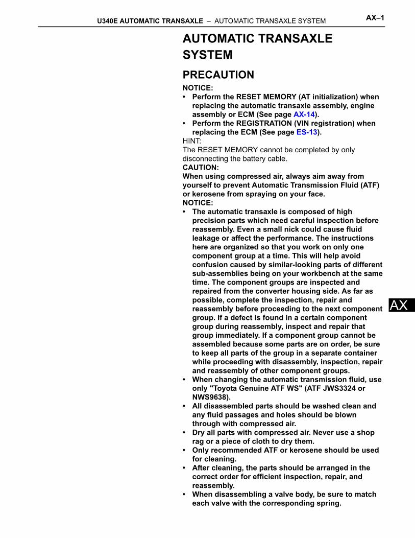
AAUTOMATIC TRANSAXLE SYSTEMPRECAUTIONNOTICE:• Perform the RESET MEMORY (AT initialization) when
replacing the automatic transaxle assembly, engine assembly or ECM (See page AX-14).
• Perform the REGISTRATION (VIN registration) when replacing the ECM (See page ES-13).
HINT:The RESET MEMORY cannot be completed by only disconnecting the battery cable.CAUTION:When using compressed air, always aim away from yourself to prevent Automatic Transmission Fluid (ATF) or kerosene from spraying on your face.NOTICE:• The automatic transaxle is composed of high
precision parts which need careful inspection before reassembly. Even a small nick could cause fluid leakage or affect the performance. The instructions here are organized so that you work on only one component group at a time. This will help avoid confusion caused by similar-looking parts of different sub-assemblies being on your workbench at the same time. The component groups are inspected and repaired from the converter housing side. As far as possible, complete the inspection, repair and reassembly before proceeding to the next component group. If a defect is found in a certain component group during reassembly, inspect and repair that group immediately. If a component group cannot be assembled because some parts are on order, be sure to keep all parts of the group in a separate container while proceeding with disassembly, inspection, repair and reassembly of other component groups.
• When changing the automatic transmission fluid, use only "Toyota Genuine ATF WS" (ATF JWS3324 or NWS9638).
• All disassembled parts should be washed clean and any fluid passages and holes should be blown through with compressed air.
• Dry all parts with compressed air. Never use a shop rag or a piece of cloth to dry them.
• Only recommended ATF or kerosene should be used for cleaning.
• After cleaning, the parts should be arranged in the correct order for efficient inspection, repair, and reassembly.
• When disassembling a valve body, be sure to match each valve with the corresponding spring.
AX–2 U340E AUTOMATIC TRANSAXLE – AUTOMATIC TRANSAXLE SYSTEM
AX
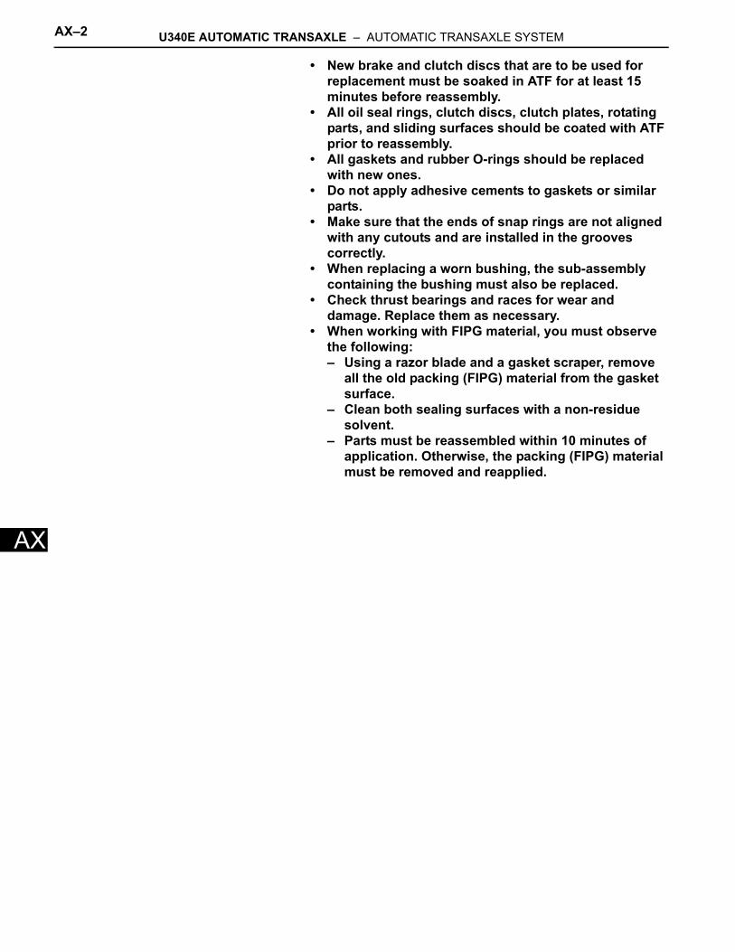
• New brake and clutch discs that are to be used for replacement must be soaked in ATF for at least 15 minutes before reassembly.
• All oil seal rings, clutch discs, clutch plates, rotating parts, and sliding surfaces should be coated with ATF prior to reassembly.
• All gaskets and rubber O-rings should be replaced with new ones.
• Do not apply adhesive cements to gaskets or similar parts.
• Make sure that the ends of snap rings are not aligned with any cutouts and are installed in the grooves correctly.
• When replacing a worn bushing, the sub-assembly containing the bushing must also be replaced.
• Check thrust bearings and races for wear and damage. Replace them as necessary.
• When working with FIPG material, you must observe the following: – Using a razor blade and a gasket scraper, remove
all the old packing (FIPG) material from the gasket surface.
– Clean both sealing surfaces with a non-residue solvent.
– Parts must be reassembled within 10 minutes of application. Otherwise, the packing (FIPG) material must be removed and reapplied.
U340E AUTOMATIC TRANSAXLE – AUTOMATIC TRANSAXLE SYSTEM AX–3
X
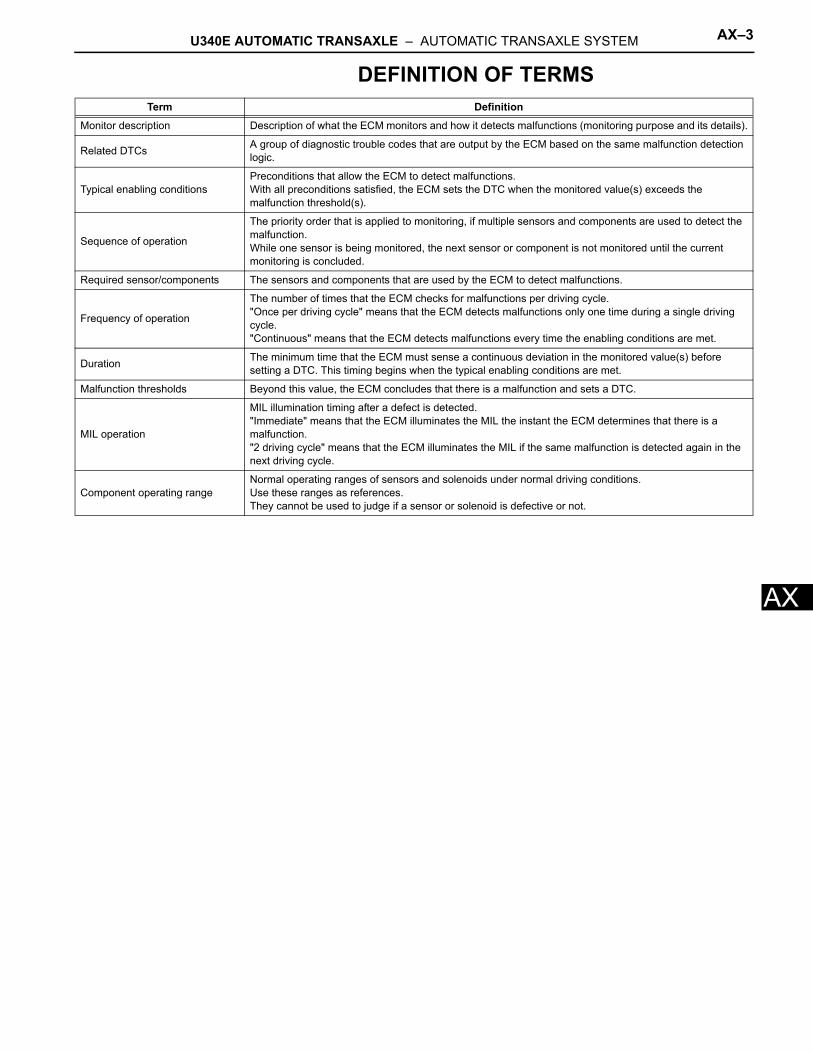
ADEFINITION OF TERMSTerm Definition
Monitor description Description of what the ECM monitors and how it detects malfunctions (monitoring purpose and its details).
Related DTCs A group of diagnostic trouble codes that are output by the ECM based on the same malfunction detection logic.
Typical enabling conditionsPreconditions that allow the ECM to detect malfunctions.With all preconditions satisfied, the ECM sets the DTC when the monitored value(s) exceeds the malfunction threshold(s).
Sequence of operation
The priority order that is applied to monitoring, if multiple sensors and components are used to detect the malfunction.While one sensor is being monitored, the next sensor or component is not monitored until the current monitoring is concluded.
Required sensor/components The sensors and components that are used by the ECM to detect malfunctions.
Frequency of operation
The number of times that the ECM checks for malfunctions per driving cycle."Once per driving cycle" means that the ECM detects malfunctions only one time during a single driving cycle."Continuous" means that the ECM detects malfunctions every time the enabling conditions are met.
Duration The minimum time that the ECM must sense a continuous deviation in the monitored value(s) before setting a DTC. This timing begins when the typical enabling conditions are met.
Malfunction thresholds Beyond this value, the ECM concludes that there is a malfunction and sets a DTC.
MIL operation
MIL illumination timing after a defect is detected."Immediate" means that the ECM illuminates the MIL the instant the ECM determines that there is a malfunction."2 driving cycle" means that the ECM illuminates the MIL if the same malfunction is detected again in the next driving cycle.
Component operating rangeNormal operating ranges of sensors and solenoids under normal driving conditions.Use these ranges as references.They cannot be used to judge if a sensor or solenoid is defective or not.
AX–4 U340E AUTOMATIC TRANSAXLE – AUTOMATIC TRANSAXLE SYSTEM
AX
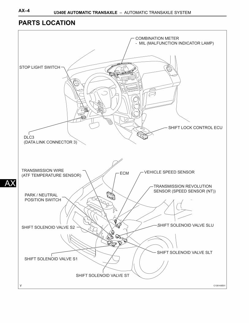
PARTS LOCATION
PARK / NEUTRAL
POSITION SWITCH
TRANSMISSION REVOLUTION
SENSOR (SPEED SENSOR (NT))
VEHICLE SPEED SENSOR
STOP LIGHT SWITCH
COMBINATION METER
- MIL (MALFUNCTION INDICATOR LAMP)
DLC3
(DATA LINK CONNECTOR 3)
ECM
SHIFT SOLENOID VALVE S2
SHIFT SOLENOID VALVE S1
SHIFT SOLENOID VALVE ST
SHIFT SOLENOID VALVE SLU
SHIFT SOLENOID VALVE SLT
SHIFT LOCK CONTROL ECU
TRANSMISSION WIRE
(ATF TEMPERATURE SENSOR)
C130143E01
U340E AUTOMATIC TRANSAXLE – AUTOMATIC TRANSAXLE SYSTEM AX–5
X
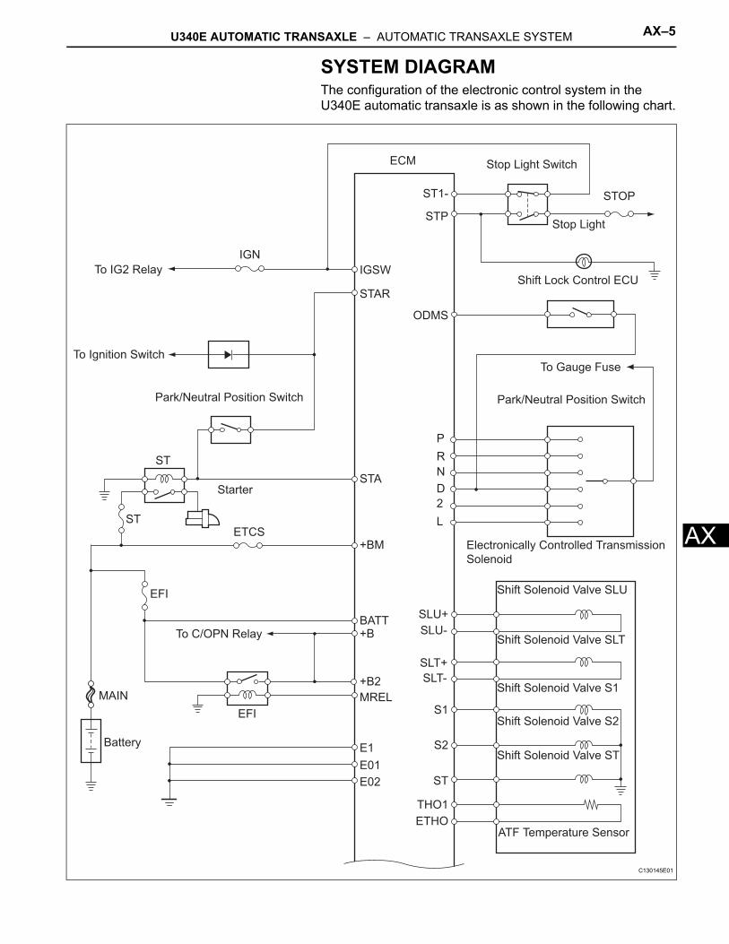
ASYSTEM DIAGRAMThe configuration of the electronic control system in the U340E automatic transaxle is as shown in the following chart.
To IG2 Relay
To Ignition Switch
Park/Neutral Position Switch
ST
Starter
ETCSST
EFI
To C/OPN Relay
MAIN
Battery
EFI
IGN
ECM
IGSW
STAR
STA
+BM
BATT+B
+B2
MREL
ST1-
STP
SLU+
SLU-
SLT+
SLT-
S1
S2
ST
THO1
ETHO
Stop Light Switch
Stop Light
STOP
Electronically Controlled Transmission
Solenoid
Shift Solenoid Valve SLU
Shift Solenoid Valve SLT
Shift Solenoid Valve S1
Shift Solenoid Valve S2
Shift Solenoid Valve ST
ATF Temperature Sensor
ODMS
P
R
N
D
2
L
Shift Lock Control ECU
To Gauge Fuse
Park/Neutral Position Switch
E1
E01
E02
C130145E01
AX–6 U340E AUTOMATIC TRANSAXLE – AUTOMATIC TRANSAXLE SYSTEM
AX
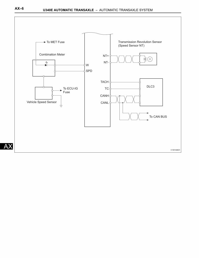
W
SPD
TACH
TC
CANH
CANL
NT+
NT-
To MET Fuse
Combination Meter
DLC3
To CAN BUS
Transmission Revolution Sensor
(Speed Sensor NT)
To ECU-IG
Fuse
Vehicle Speed Sensor
C130144E01
U340E AUTOMATIC TRANSAXLE – AUTOMATIC TRANSAXLE SYSTEM AX–7
X
ASYSTEM DESCRIPTION1. SYSTEM DESCRIPTION
(a) The ECT (Electronic Controlled automatic Transmission/Transaxle) is an automatic transmission/transaxle that electronically controls shift timing using the ECM. The ECM detects electrical signals that indicate engine and driving conditions, and controls the shift point, based on driver habits and road conditions. As a result, fuel efficiency and power transmission/transaxle performance are improved.Shift shock has been reduced by controlling the engine and transmission simultaneously.In addition, the ECT has features such as the following:• Diagnostic function• Fail-safe function when a malfunction occurs
AX–8 U340E AUTOMATIC TRANSAXLE – AUTOMATIC TRANSAXLE SYSTEM
AX
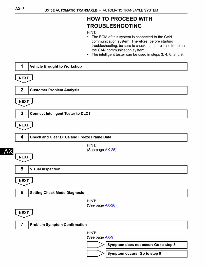
HOW TO PROCEED WITH TROUBLESHOOTINGHINT:• The ECM of this system is connected to the CAN
communication system. Therefore, before starting troubleshooting, be sure to check that there is no trouble in the CAN communication system.
• The intelligent tester can be used in steps 3, 4, 6, and 9.
NEXT
NEXT
NEXT
HINT:(See page AX-25).
NEXT
NEXT
HINT:(See page AX-26).
NEXT
HINT:(See page AX-9).
1 Vehicle Brought to Workshop
2 Customer Problem Analysis
3 Connect Intelligent Tester to DLC3
4 Check and Clear DTCs and Freeze Frame Data
5 Visual Inspection
6 Setting Check Mode Diagnosis
7 Problem Symptom Confirmation
Symptom does not occur: Go to step 8
Symptom occurs: Go to step 9
U340E AUTOMATIC TRANSAXLE – AUTOMATIC TRANSAXLE SYSTEM AX–9
X
AHINT:(See page IN-26).
NEXT
HINT:(See page AX-25).
HINT:(See page AX-93, AX-106 and AX-107).
NG
OK
HINT:(See page AX-11).
NG
OK
HINT:(See page AX-13).
NG
OK
HINT:(See page AX-14).
NG
OK
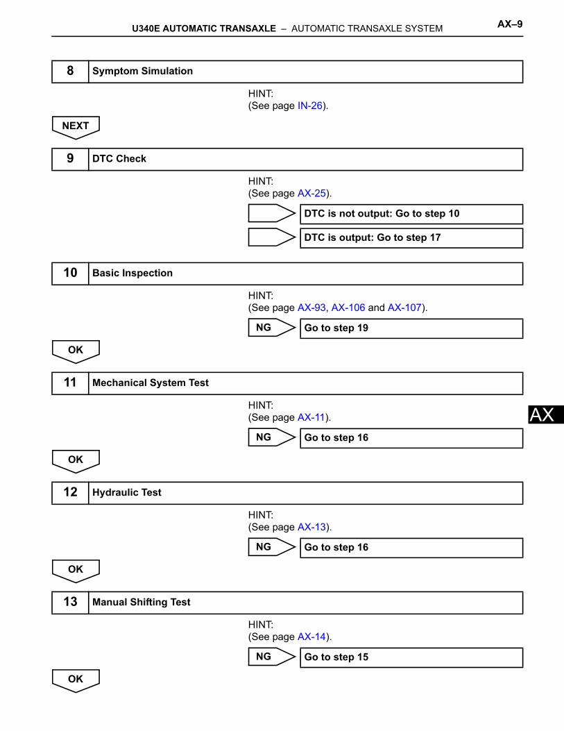
8 Symptom Simulation
9 DTC Check
DTC is not output: Go to step 10
DTC is output: Go to step 17
10 Basic Inspection
Go to step 19
11 Mechanical System Test
Go to step 16
12 Hydraulic Test
Go to step 16
13 Manual Shifting Test
Go to step 15
AX–10 U340E AUTOMATIC TRANSAXLE – AUTOMATIC TRANSAXLE SYSTEM
AX
HINT:(See page AX-17).
NG
OK
HINT:(See page AX-17).
NEXT
HINT:(See page AX-32).
NEXT
NEXT
NEXT
NEXT
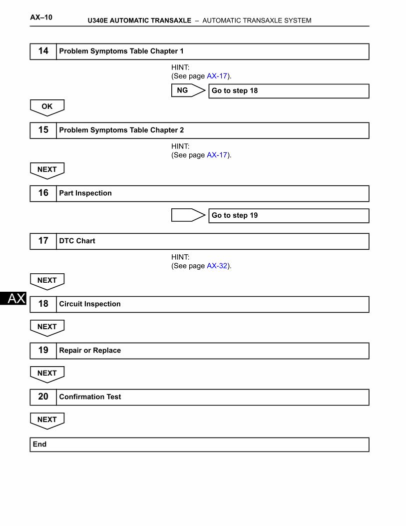
14 Problem Symptoms Table Chapter 1
Go to step 18
15 Problem Symptoms Table Chapter 2
16 Part Inspection
Go to step 19
17 DTC Chart
18 Circuit Inspection
19 Repair or Replace
20 Confirmation Test
End
U340E AUTOMATIC TRANSAXLE – AUTOMATIC TRANSAXLE SYSTEM AX–11
X
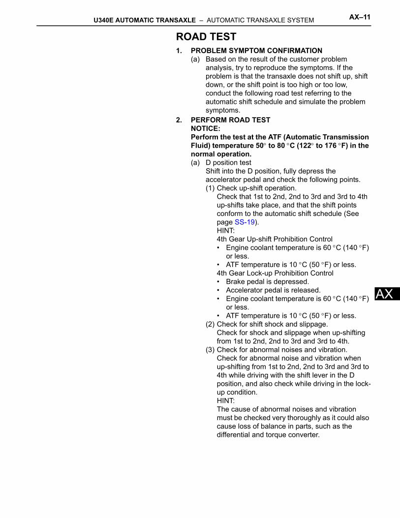
AROAD TEST1. PROBLEM SYMPTOM CONFIRMATION
(a) Based on the result of the customer problem analysis, try to reproduce the symptoms. If the problem is that the transaxle does not shift up, shift down, or the shift point is too high or too low, conduct the following road test referring to the automatic shift schedule and simulate the problem symptoms.
2. PERFORM ROAD TESTNOTICE:Perform the test at the ATF (Automatic Transmission Fluid) temperature 50° to 80 °C (122° to 176 °F) in the normal operation.(a) D position test
Shift into the D position, fully depress the accelerator pedal and check the following points.(1) Check up-shift operation.
Check that 1st to 2nd, 2nd to 3rd and 3rd to 4th up-shifts take place, and that the shift points conform to the automatic shift schedule (See page SS-19).HINT:4th Gear Up-shift Prohibition Control• Engine coolant temperature is 60 °C (140 °F)
or less. • ATF temperature is 10 °C (50 °F) or less.4th Gear Lock-up Prohibition Control• Brake pedal is depressed.• Accelerator pedal is released.• Engine coolant temperature is 60 °C (140 °F)
or less.• ATF temperature is 10 °C (50 °F) or less.
(2) Check for shift shock and slippage.Check for shock and slippage when up-shifting from 1st to 2nd, 2nd to 3rd and 3rd to 4th.
(3) Check for abnormal noises and vibration.Check for abnormal noise and vibration when up-shifting from 1st to 2nd, 2nd to 3rd and 3rd to 4th while driving with the shift lever in the D position, and also check while driving in the lock-up condition.HINT:The cause of abnormal noises and vibration must be checked very thoroughly as it could also cause loss of balance in parts, such as the differential and torque converter.
AX–12 U340E AUTOMATIC TRANSAXLE – AUTOMATIC TRANSAXLE SYSTEM
AX
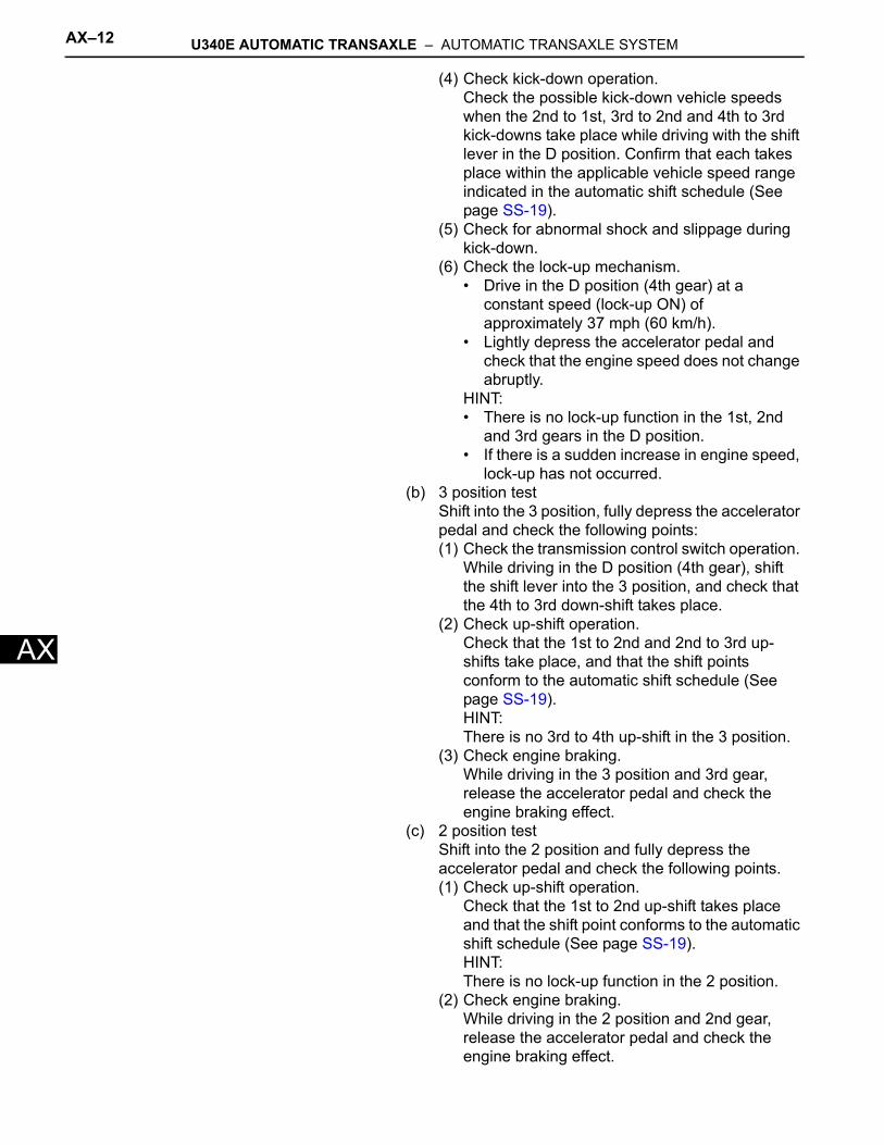
(4) Check kick-down operation.Check the possible kick-down vehicle speeds when the 2nd to 1st, 3rd to 2nd and 4th to 3rd kick-downs take place while driving with the shift lever in the D position. Confirm that each takes place within the applicable vehicle speed range indicated in the automatic shift schedule (See page SS-19).
(5) Check for abnormal shock and slippage during kick-down.
(6) Check the lock-up mechanism.• Drive in the D position (4th gear) at a
constant speed (lock-up ON) of approximately 37 mph (60 km/h).
• Lightly depress the accelerator pedal and check that the engine speed does not change abruptly.
HINT:• There is no lock-up function in the 1st, 2nd
and 3rd gears in the D position.• If there is a sudden increase in engine speed,
lock-up has not occurred.(b) 3 position test
Shift into the 3 position, fully depress the accelerator pedal and check the following points:(1) Check the transmission control switch operation.
While driving in the D position (4th gear), shift the shift lever into the 3 position, and check that the 4th to 3rd down-shift takes place.
(2) Check up-shift operation.Check that the 1st to 2nd and 2nd to 3rd up-shifts take place, and that the shift points conform to the automatic shift schedule (See page SS-19).HINT:There is no 3rd to 4th up-shift in the 3 position.
(3) Check engine braking.While driving in the 3 position and 3rd gear, release the accelerator pedal and check the engine braking effect.
(c) 2 position testShift into the 2 position and fully depress the accelerator pedal and check the following points.(1) Check up-shift operation.
Check that the 1st to 2nd up-shift takes place and that the shift point conforms to the automatic shift schedule (See page SS-19).HINT:There is no lock-up function in the 2 position.
(2) Check engine braking.While driving in the 2 position and 2nd gear, release the accelerator pedal and check the engine braking effect.
U340E AUTOMATIC TRANSAXLE – AUTOMATIC TRANSAXLE SYSTEM AX–13
X
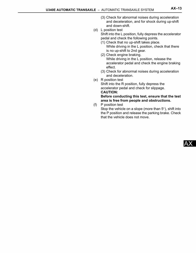
A(3) Check for abnormal noises during acceleration and deceleration, and for shock during up-shift and down-shift.
(d) L position testShift into the L position, fully depress the accelerator pedal and check the following points.(1) Check that no up-shift takes place.
While driving in the L position, check that there is no up-shift to 2nd gear.
(2) Check engine braking.While driving in the L position, release the accelerator pedal and check the engine braking effect.
(3) Check for abnormal noises during acceleration and deceleration.
(e) R position testShift into the R position, fully depress the accelerator pedal and check for slippage.CAUTION:Before conducting this test, ensure that the test area is free from people and obstructions.
(f) P position testStop the vehicle on a slope (more than 5°), shift into the P position and release the parking brake. Check that the vehicle does not move.
AX–14 U340E AUTOMATIC TRANSAXLE – AUTOMATIC TRANSAXLE SYSTEM
AX
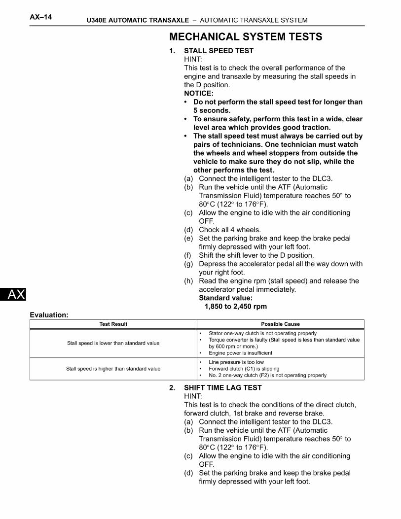
MECHANICAL SYSTEM TESTS1. STALL SPEED TEST
HINT:This test is to check the overall performance of the engine and transaxle by measuring the stall speeds in the D position.NOTICE:• Do not perform the stall speed test for longer than
5 seconds.• To ensure safety, perform this test in a wide, clear
level area which provides good traction.• The stall speed test must always be carried out by
pairs of technicians. One technician must watch the wheels and wheel stoppers from outside the vehicle to make sure they do not slip, while the other performs the test.
(a) Connect the intelligent tester to the DLC3.(b) Run the vehicle until the ATF (Automatic
Transmission Fluid) temperature reaches 50° to 80°C (122° to 176°F).
(c) Allow the engine to idle with the air conditioning OFF.
(d) Chock all 4 wheels.(e) Set the parking brake and keep the brake pedal
firmly depressed with your left foot.(f) Shift the shift lever to the D position.(g) Depress the accelerator pedal all the way down with
your right foot.(h) Read the engine rpm (stall speed) and release the
accelerator pedal immediately.Standard value:
1,850 to 2,450 rpmEvaluation:
2. SHIFT TIME LAG TESTHINT:This test is to check the conditions of the direct clutch, forward clutch, 1st brake and reverse brake.(a) Connect the intelligent tester to the DLC3.(b) Run the vehicle until the ATF (Automatic
Transmission Fluid) temperature reaches 50° to 80°C (122° to 176°F).
(c) Allow the engine to idle with the air conditioning OFF.
(d) Set the parking brake and keep the brake pedal firmly depressed with your left foot.
Test Result Possible Cause
Stall speed is lower than standard value
• Stator one-way clutch is not operating properly• Torque converter is faulty (Stall speed is less than standard value
by 600 rpm or more.)• Engine power is insufficient
Stall speed is higher than standard value• Line pressure is too low• Forward clutch (C1) is slipping• No. 2 one-way clutch (F2) is not operating properly
U340E AUTOMATIC TRANSAXLE – AUTOMATIC TRANSAXLE SYSTEM AX–15
X
A(e) Check the D range time lag.(1) Shift the shift lever into the N position and wait
for 1 minute. (*1)(2) Shift the shift lever into the D position and
measure the time until the shock is felt. (*2)(3) Repeat procedures (*1) and (*2) three times, and
calculate the average time of the three tests.(f) Check the R range time lag.
(1) Shift the shift lever into the N position and wait for 1 minute. (*3)
(2) Shift the shift lever into the R position and measure the time until the shock is felt. (*4)
(3) Repeat procedures (*3) and (*4) three times, and calculate the average time of the three tests.Standard value:
D range time lag is less than 1.2 secondsR range time lag is less than 1.5 seconds
Evaluation :
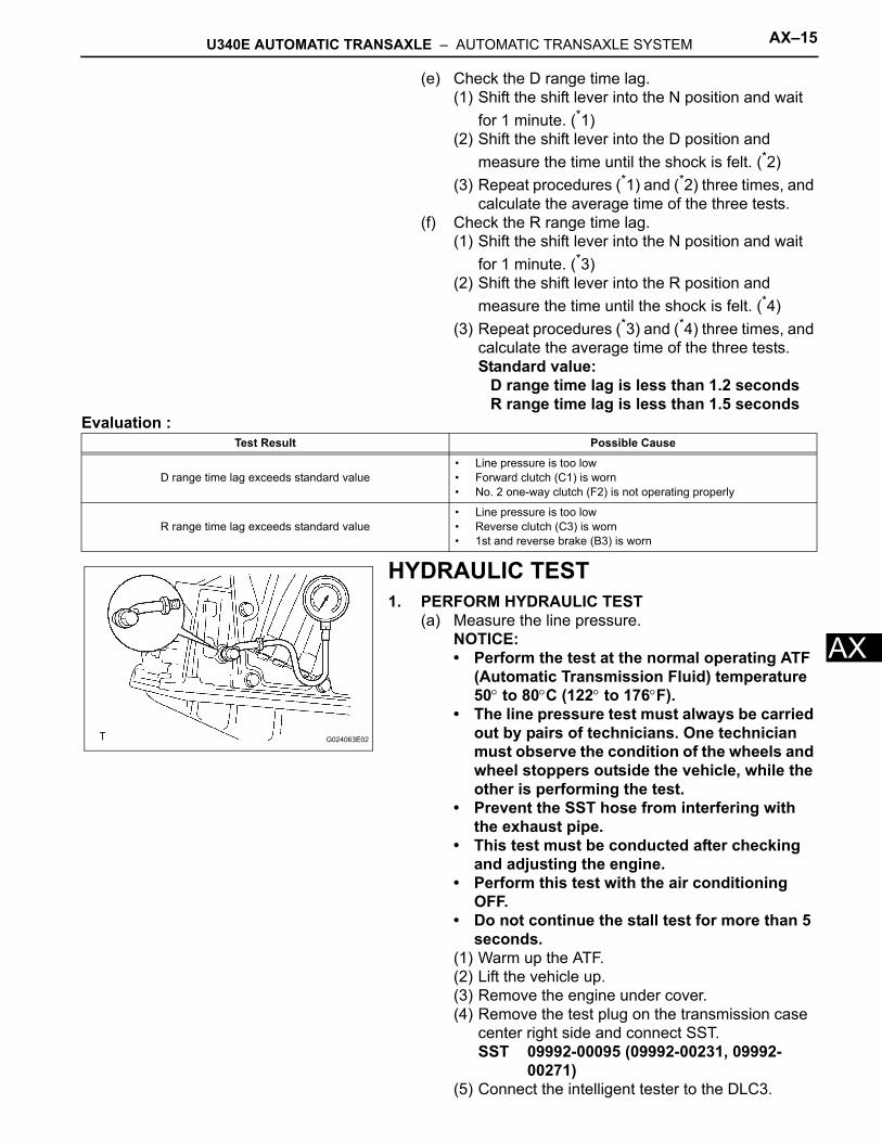
HYDRAULIC TEST1. PERFORM HYDRAULIC TEST
(a) Measure the line pressure.NOTICE:• Perform the test at the normal operating ATF
(Automatic Transmission Fluid) temperature 50° to 80°C (122° to 176°F).
• The line pressure test must always be carried out by pairs of technicians. One technician must observe the condition of the wheels and wheel stoppers outside the vehicle, while the other is performing the test.
• Prevent the SST hose from interfering with the exhaust pipe.
• This test must be conducted after checking and adjusting the engine.
• Perform this test with the air conditioning OFF.
• Do not continue the stall test for more than 5 seconds.
(1) Warm up the ATF.(2) Lift the vehicle up.(3) Remove the engine under cover.(4) Remove the test plug on the transmission case
center right side and connect SST.SST 09992-00095 (09992-00231, 09992-
00271)(5) Connect the intelligent tester to the DLC3.
Test Result Possible Cause
D range time lag exceeds standard value• Line pressure is too low• Forward clutch (C1) is worn• No. 2 one-way clutch (F2) is not operating properly
R range time lag exceeds standard value• Line pressure is too low• Reverse clutch (C3) is worn• 1st and reverse brake (B3) is worn
G024063E02
AX–16 U340E AUTOMATIC TRANSAXLE – AUTOMATIC TRANSAXLE SYSTEM
AX
(6) Fully apply the parking brake and chock all 4 wheels.
(7) Start the engine and check the idling speed.(8) Keep your left foot pressing firmly on the brake
pedal and shift into the D position.(9) Measure the line pressure when the engine is
idling.(10)Depress the accelerator pedal all the way down.
Quickly read the highest line pressure when engine speed reaches stall speed.
(11)Perform the test in the R position in the same manner.
Standard line pressure
Evaluation:
Condition D position kPa (kgf / cm2, psi) R position kPa (kgf / cm2, psi)
Idling372 to 412 kPa
(3.8 to 4.2 kgf/cm2, 54 to 60 psi)553 to 623 kPa
(5.6 to 6.4 kgf/cm2, 80 to 90 psi)
Stall1,126 to 1,226 kPa
(11.5 to 12.5 kgf/cm2, 163 to 178 psi)1,664 to 1,864 kPa
(17.0 to 19.0 kgf/cm2, 241 to 270 psi)
Problem Possible Cause
Measured values are higher than specified values in all positions • Shift solenoid valve SLT defective• Regulator valve defective
Measured values are lower than specified values in all positions• Shift solenoid valve SLT defective• Regulator valve defective• Oil pump defective
Pressure is low in D position only • D position circuit fluid leak• Forward clutch defective
Pressure is low in R position only• R position circuit fluid leak• Reverse clutch defective• 1st and reverse brake defective
U340E AUTOMATIC TRANSAXLE – AUTOMATIC TRANSAXLE SYSTEM AX–17
X
AMANUAL SHIFTING TEST1. PERFORM MANUAL SHIFTING TEST
HINT:• This test can be used to determine whether the
trouble is occurring in the electrical circuit or is a mechanical problem in the transaxle.
• If any abnormalities are found in the following test, the problem is in the transaxle itself.
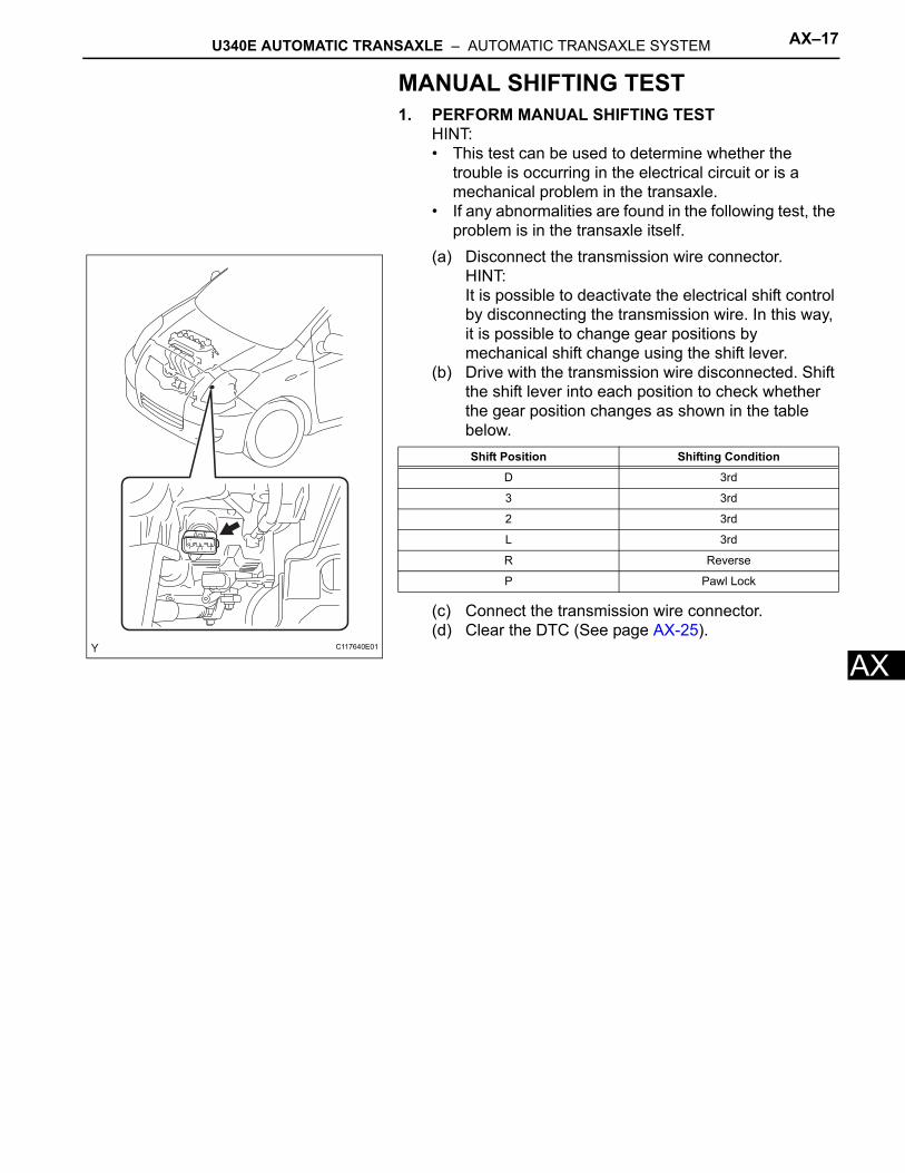
(a) Disconnect the transmission wire connector.HINT:It is possible to deactivate the electrical shift control by disconnecting the transmission wire. In this way, it is possible to change gear positions by mechanical shift change using the shift lever.
(b) Drive with the transmission wire disconnected. Shift the shift lever into each position to check whether the gear position changes as shown in the table below.
(c) Connect the transmission wire connector.(d) Clear the DTC (See page AX-25).
C117640E01
Shift Position Shifting Condition
D 3rd
3 3rd
2 3rd
L 3rd
R Reverse
P Pawl Lock
AX–18 U340E AUTOMATIC TRANSAXLE – AUTOMATIC TRANSAXLE SYSTEM
AX
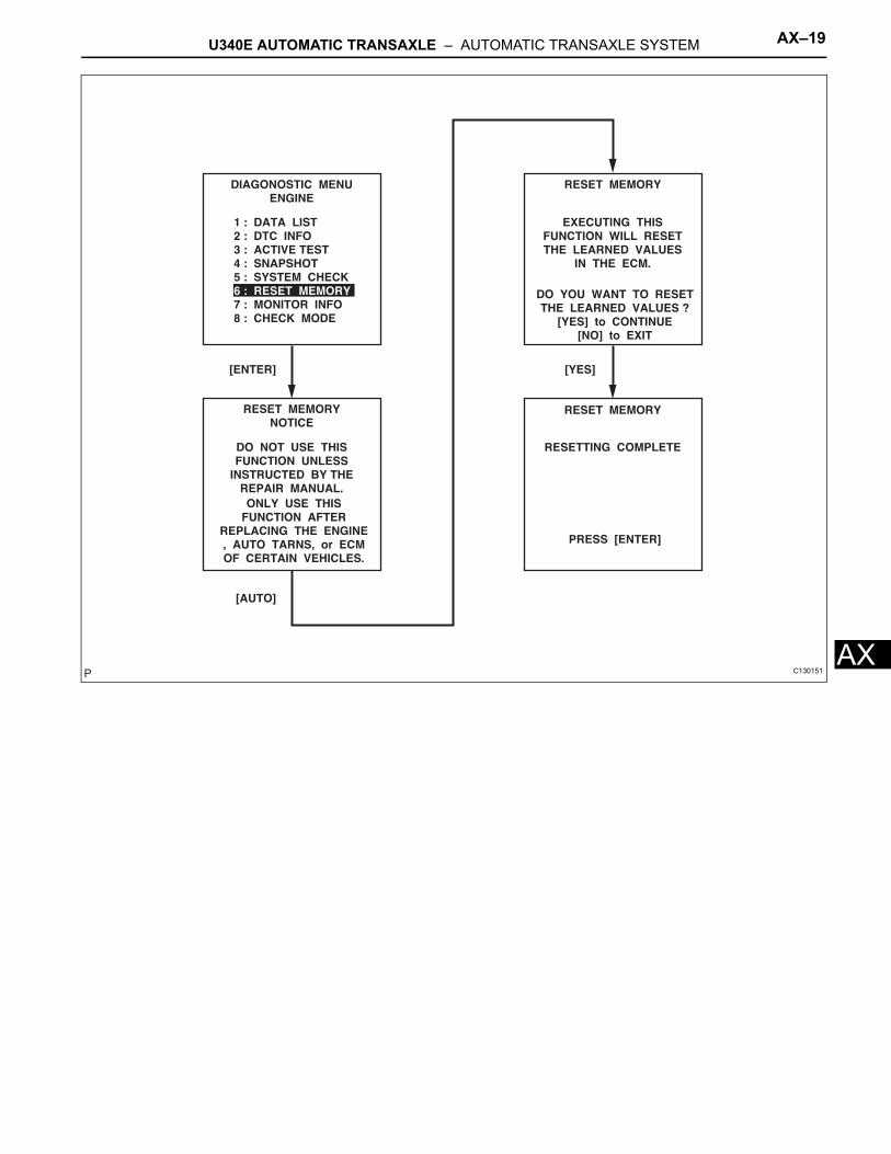
INITIALIZATION1. RESET MEMORY
NOTICE:• Perform the RESET MEMORY (AT initialization)
when replacing the automatic transaxle assembly, engine assembly or ECM.
• The RESET MEMORY can only be performed using an intelligent tester.
HINT:The ECM stores the conditions that the ECT controls the automatic transaxle assembly and engine assembly in accordance with those characteristics. Therefore, when the automatic transaxle assembly, engine assembly, or ECM is replaced, it is necessary to reset the memory so that the ECM can store the new information.The reset procedure is as follows.(a) Turn the ignition switch off.(b) Connect the intelligent tester to the DLC3.(c) Turn the ignition switch to the ON position and push
the intelligent tester main switch on.(d) Select the following items: DIAGNOSIS /
ENHANCED OBD II.(e) Perform the reset memory procedure from the
ENGINE menu.CAUTION:After performing the RESET MEMORY, be sure to perform the ROAD TEST (See page AX-9) as described earlier.HINT:The ECM stores learned values by performing the ROAD TEST.(1) Tester menu flow:
U340E AUTOMATIC TRANSAXLE – AUTOMATIC TRANSAXLE SYSTEM AX–19
X
AC130151
AX–20 U340E AUTOMATIC TRANSAXLE – AUTOMATIC TRANSAXLE SYSTEM
AX
MONITOR DRIVE PATTERN1. MONITOR DRIVE PATTERN FOR ECT TEST
(a) Perform this drive pattern as one method to simulate the detection conditions of ECT malfunctions. (The DTCs may not be detected due to the actual driving conditions. And some DTCs may not be detected through this drive pattern.)HINT:Preparation for driving• Warm up the engine. (Engine coolant
temperature is 60°C (140°F) or higher.)• Drive the vehicle when the atmospheric
temperature is -10°C (14°F) or higher. (Malfunction is not detected when the atmospheric temperature is less than -10°C (14°F).)
Driving note• Drive the vehicle through all gears.
Stop → 1st → 2nd → 3rd → 4th (lock-up ON).• Repeat the above driving pattern three times or
more.NOTICE:• The monitor status can be checked using the
intelligent tester. When using an intelligent tester, monitor status can be found in the ENHANCED OBD II / DATA LIST or under CARB OBD II.
• In the event that the drive pattern must be interrupted (possibly due to traffic conditions or other factors), the drive pattern can be resumed and, in most cases, the monitor can be completed.
CAUTION:Perform this drive pattern on as level a road as possible and strictly observe the posted speed limits and traffic laws while driving.
U340E AUTOMATIC TRANSAXLE – AUTOMATIC TRANSAXLE SYSTEM AX–21
X
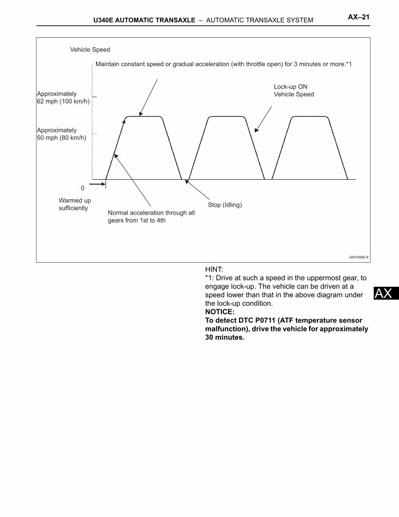
AHINT:*1: Drive at such a speed in the uppermost gear, to engage lock-up. The vehicle can be driven at a speed lower than that in the above diagram under the lock-up condition.NOTICE:To detect DTC P0711 (ATF temperature sensor malfunction), drive the vehicle for approximately 30 minutes.
Vehicle Speed
Maintain constant speed or gradual acceleration (with throttle open) for 3 minutes or more.*1
Lock-up ON
Vehicle Speed
Stop (Idling)
Normal acceleration through all
gears from 1st to 4th
Warmed up
sufficiently
0
Approximately
62 mph (100 km/h)
Approximately
50 mph (80 km/h)
G031593E14
AX–22 U340E AUTOMATIC TRANSAXLE – AUTOMATIC TRANSAXLE SYSTEM
AX
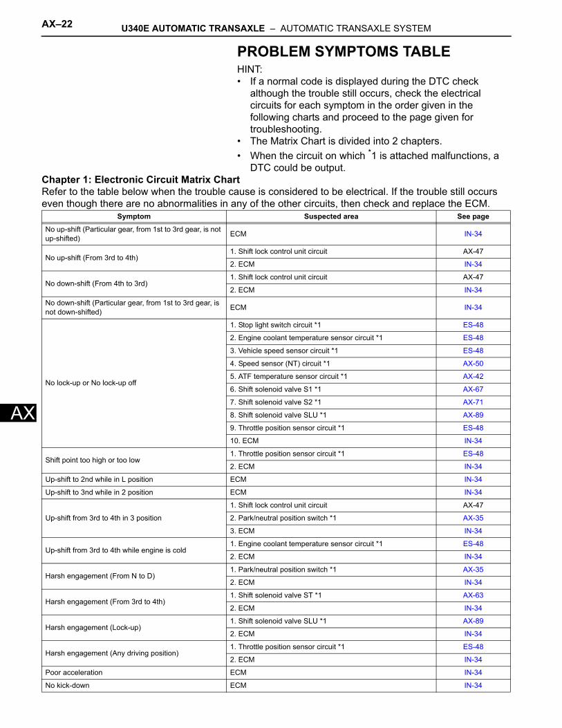
PROBLEM SYMPTOMS TABLEHINT:• If a normal code is displayed during the DTC check
although the trouble still occurs, check the electrical circuits for each symptom in the order given in the following charts and proceed to the page given for troubleshooting.
• The Matrix Chart is divided into 2 chapters.• When the circuit on which *1 is attached malfunctions, a
DTC could be output. Chapter 1: Electronic Circuit Matrix ChartRefer to the table below when the trouble cause is considered to be electrical. If the trouble still occurs even though there are no abnormalities in any of the other circuits, then check and replace the ECM.
Symptom Suspected area See page
No up-shift (Particular gear, from 1st to 3rd gear, is not up-shifted) ECM IN-34
No up-shift (From 3rd to 4th)1. Shift lock control unit circuit AX-47
2. ECM IN-34
No down-shift (From 4th to 3rd)1. Shift lock control unit circuit AX-47
2. ECM IN-34
No down-shift (Particular gear, from 1st to 3rd gear, is not down-shifted) ECM IN-34
No lock-up or No lock-up off
1. Stop light switch circuit *1 ES-48
2. Engine coolant temperature sensor circuit *1 ES-48
3. Vehicle speed sensor circuit *1 ES-48
4. Speed sensor (NT) circuit *1 AX-50
5. ATF temperature sensor circuit *1 AX-42
6. Shift solenoid valve S1 *1 AX-67
7. Shift solenoid valve S2 *1 AX-71
8. Shift solenoid valve SLU *1 AX-89
9. Throttle position sensor circuit *1 ES-48
10. ECM IN-34
Shift point too high or too low1. Throttle position sensor circuit *1 ES-48
2. ECM IN-34
Up-shift to 2nd while in L position ECM IN-34
Up-shift to 3nd while in 2 position ECM IN-34
Up-shift from 3rd to 4th in 3 position
1. Shift lock control unit circuit AX-47
2. Park/neutral position switch *1 AX-35
3. ECM IN-34
Up-shift from 3rd to 4th while engine is cold1. Engine coolant temperature sensor circuit *1 ES-48
2. ECM IN-34
Harsh engagement (From N to D)1. Park/neutral position switch *1 AX-35
2. ECM IN-34
Harsh engagement (From 3rd to 4th)1. Shift solenoid valve ST *1 AX-63
2. ECM IN-34
Harsh engagement (Lock-up)1. Shift solenoid valve SLU *1 AX-89
2. ECM IN-34
Harsh engagement (Any driving position)1. Throttle position sensor circuit *1 ES-48
2. ECM IN-34
Poor acceleration ECM IN-34
No kick-down ECM IN-34
U340E AUTOMATIC TRANSAXLE – AUTOMATIC TRANSAXLE SYSTEM AX–23
X
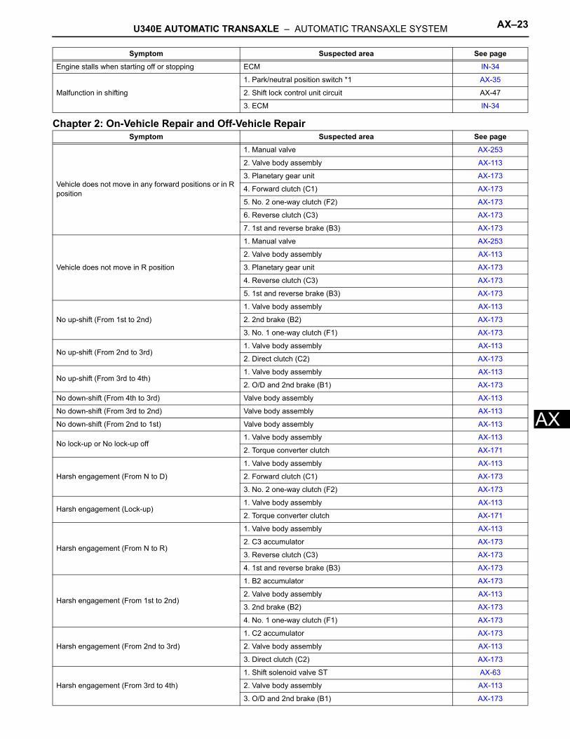
AChapter 2: On-Vehicle Repair and Off-Vehicle Repair
Engine stalls when starting off or stopping ECM IN-34
Malfunction in shifting
1. Park/neutral position switch *1 AX-35
2. Shift lock control unit circuit AX-47
3. ECM IN-34
Symptom Suspected area See page
Vehicle does not move in any forward positions or in R position
1. Manual valve AX-253
2. Valve body assembly AX-113
3. Planetary gear unit AX-173
4. Forward clutch (C1) AX-173
5. No. 2 one-way clutch (F2) AX-173
6. Reverse clutch (C3) AX-173
7. 1st and reverse brake (B3) AX-173
Vehicle does not move in R position
1. Manual valve AX-253
2. Valve body assembly AX-113
3. Planetary gear unit AX-173
4. Reverse clutch (C3) AX-173
5. 1st and reverse brake (B3) AX-173
No up-shift (From 1st to 2nd)
1. Valve body assembly AX-113
2. 2nd brake (B2) AX-173
3. No. 1 one-way clutch (F1) AX-173
No up-shift (From 2nd to 3rd)1. Valve body assembly AX-113
2. Direct clutch (C2) AX-173
No up-shift (From 3rd to 4th)1. Valve body assembly AX-113
2. O/D and 2nd brake (B1) AX-173
No down-shift (From 4th to 3rd) Valve body assembly AX-113
No down-shift (From 3rd to 2nd) Valve body assembly AX-113
No down-shift (From 2nd to 1st) Valve body assembly AX-113
No lock-up or No lock-up off1. Valve body assembly AX-113
2. Torque converter clutch AX-171
Harsh engagement (From N to D)
1. Valve body assembly AX-113
2. Forward clutch (C1) AX-173
3. No. 2 one-way clutch (F2) AX-173
Harsh engagement (Lock-up)1. Valve body assembly AX-113
2. Torque converter clutch AX-171
Harsh engagement (From N to R)
1. Valve body assembly AX-113
2. C3 accumulator AX-173
3. Reverse clutch (C3) AX-173
4. 1st and reverse brake (B3) AX-173
Harsh engagement (From 1st to 2nd)
1. B2 accumulator AX-173
2. Valve body assembly AX-113
3. 2nd brake (B2) AX-173
4. No. 1 one-way clutch (F1) AX-173
Harsh engagement (From 2nd to 3rd)
1. C2 accumulator AX-173
2. Valve body assembly AX-113
3. Direct clutch (C2) AX-173
Harsh engagement (From 3rd to 4th)
1. Shift solenoid valve ST AX-63
2. Valve body assembly AX-113
3. O/D and 2nd brake (B1) AX-173
Symptom Suspected area See page
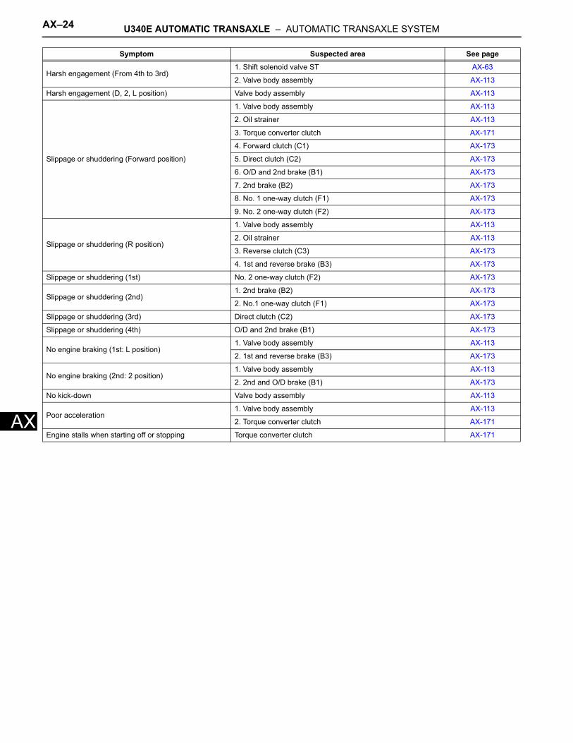
AX–24 U340E AUTOMATIC TRANSAXLE – AUTOMATIC TRANSAXLE SYSTEM
AX
Harsh engagement (From 4th to 3rd)1. Shift solenoid valve ST AX-63
2. Valve body assembly AX-113
Harsh engagement (D, 2, L position) Valve body assembly AX-113
Slippage or shuddering (Forward position)
1. Valve body assembly AX-113
2. Oil strainer AX-113
3. Torque converter clutch AX-171
4. Forward clutch (C1) AX-173
5. Direct clutch (C2) AX-173
6. O/D and 2nd brake (B1) AX-173
7. 2nd brake (B2) AX-173
8. No. 1 one-way clutch (F1) AX-173
9. No. 2 one-way clutch (F2) AX-173
Slippage or shuddering (R position)
1. Valve body assembly AX-113
2. Oil strainer AX-113
3. Reverse clutch (C3) AX-173
4. 1st and reverse brake (B3) AX-173
Slippage or shuddering (1st) No. 2 one-way clutch (F2) AX-173
Slippage or shuddering (2nd)1. 2nd brake (B2) AX-173
2. No.1 one-way clutch (F1) AX-173
Slippage or shuddering (3rd) Direct clutch (C2) AX-173
Slippage or shuddering (4th) O/D and 2nd brake (B1) AX-173
No engine braking (1st: L position)1. Valve body assembly AX-113
2. 1st and reverse brake (B3) AX-173
No engine braking (2nd: 2 position)1. Valve body assembly AX-113
2. 2nd and O/D brake (B1) AX-173
No kick-down Valve body assembly AX-113
Poor acceleration1. Valve body assembly AX-113
2. Torque converter clutch AX-171
Engine stalls when starting off or stopping Torque converter clutch AX-171
Symptom Suspected area See page
U340E AUTOMATIC TRANSAXLE – AUTOMATIC TRANSAXLE SYSTEM AX–25
X
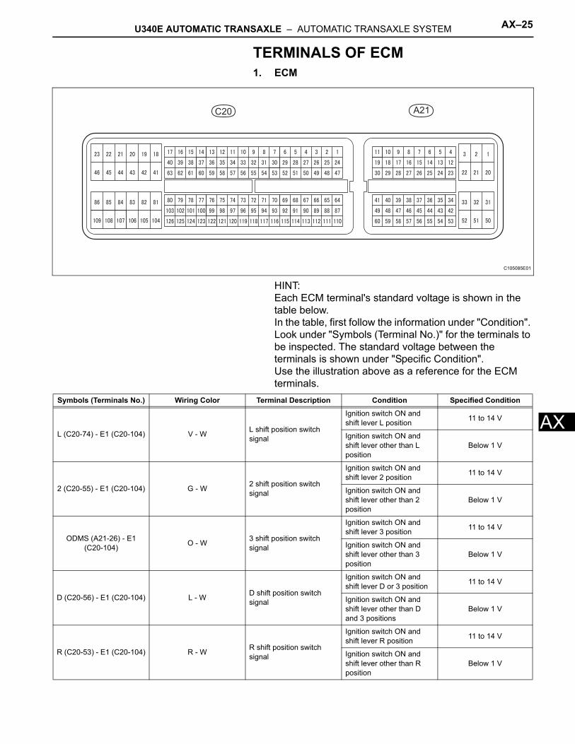
ATERMINALS OF ECM1. ECM
HINT:Each ECM terminal's standard voltage is shown in the table below.In the table, first follow the information under "Condition". Look under "Symbols (Terminal No.)" for the terminals to be inspected. The standard voltage between the terminals is shown under "Specific Condition".Use the illustration above as a reference for the ECM terminals.
C20 A21
C105085E01
Symbols (Terminals No.) Wiring Color Terminal Description Condition Specified Condition
L (C20-74) - E1 (C20-104) V - W L shift position switch signal
Ignition switch ON and shift lever L position 11 to 14 V
Ignition switch ON and shift lever other than L position
Below 1 V
2 (C20-55) - E1 (C20-104) G - W 2 shift position switch signal
Ignition switch ON and shift lever 2 position 11 to 14 V
Ignition switch ON and shift lever other than 2 position
Below 1 V
ODMS (A21-26) - E1 (C20-104) O - W 3 shift position switch
signal
Ignition switch ON and shift lever 3 position 11 to 14 V
Ignition switch ON and shift lever other than 3 position
Below 1 V
D (C20-56) - E1 (C20-104) L - W D shift position switch signal
Ignition switch ON and shift lever D or 3 position 11 to 14 V
Ignition switch ON and shift lever other than D and 3 positions
Below 1 V
R (C20-53) - E1 (C20-104) R - W R shift position switch signal
Ignition switch ON and shift lever R position 11 to 14 V
Ignition switch ON and shift lever other than R position
Below 1 V
AX–26 U340E AUTOMATIC TRANSAXLE – AUTOMATIC TRANSAXLE SYSTEM
AX
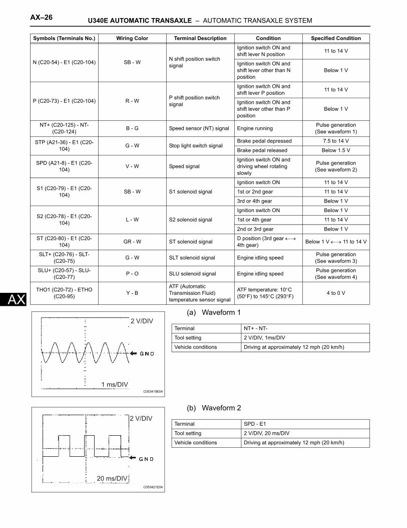
(a) Waveform 1(b) Waveform 2
N (C20-54) - E1 (C20-104) SB - W N shift position switch signal
Ignition switch ON and shift lever N position 11 to 14 V
Ignition switch ON and shift lever other than N position
Below 1 V
P (C20-73) - E1 (C20-104) R - W P shift position switch signal
Ignition switch ON and shift lever P position 11 to 14 V
Ignition switch ON and shift lever other than P position
Below 1 V
NT+ (C20-125) - NT- (C20-124) B - G Speed sensor (NT) signal Engine running Pulse generation
(See waveform 1)
STP (A21-36) - E1 (C20-104) G - W Stop light switch signal
Brake pedal depressed 7.5 to 14 V
Brake pedal released Below 1.5 V
SPD (A21-8) - E1 (C20-104) V - W Speed signal
Ignition switch ON and driving wheel rotating slowly
Pulse generation(See waveform 2)
S1 (C20-79) - E1 (C20-104) SB - W S1 solenoid signal
Ignition switch ON 11 to 14 V
1st or 2nd gear 11 to 14 V
3rd or 4th gear Below 1 V
S2 (C20-78) - E1 (C20-104) L - W S2 solenoid signal
Ignition switch ON Below 1 V
1st or 4th gear 11 to 14 V
2nd or 3rd gear Below 1 V
ST (C20-80) - E1 (C20-104) GR - W ST solenoid signal D position (3rd gear ←→
4th gear) Below 1 V ←→ 11 to 14 V
SLT+ (C20-76) - SLT- (C20-75) G - W SLT solenoid signal Engine idling speed Pulse generation
(See waveform 3)
SLU+ (C20-57) - SLU- (C20-77) P - O SLU solenoid signal Engine idling speed Pulse generation
(See waveform 4)
THO1 (C20-72) - ETHO (C20-95) Y - B
ATF (Automatic Transmission Fluid) temperature sensor signal
ATF temperature: 10°C (50°F) to 145°C (293°F) 4 to 0 V
Symbols (Terminals No.) Wiring Color Terminal Description Condition Specified Condition
2 V/DIV
1 ms/DIVC053419E04
Terminal NT+ - NT-
Tool setting 2 V/DIV, 1ms/DIV
Vehicle conditions Driving at approximately 12 mph (20 km/h)
2 V/DIV
20 ms/DIVC053421E04
Terminal SPD - E1
Tool setting 2 V/DIV, 20 ms/DIV
Vehicle conditions Driving at approximately 12 mph (20 km/h)
U340E AUTOMATIC TRANSAXLE – AUTOMATIC TRANSAXLE SYSTEM AX–27
X
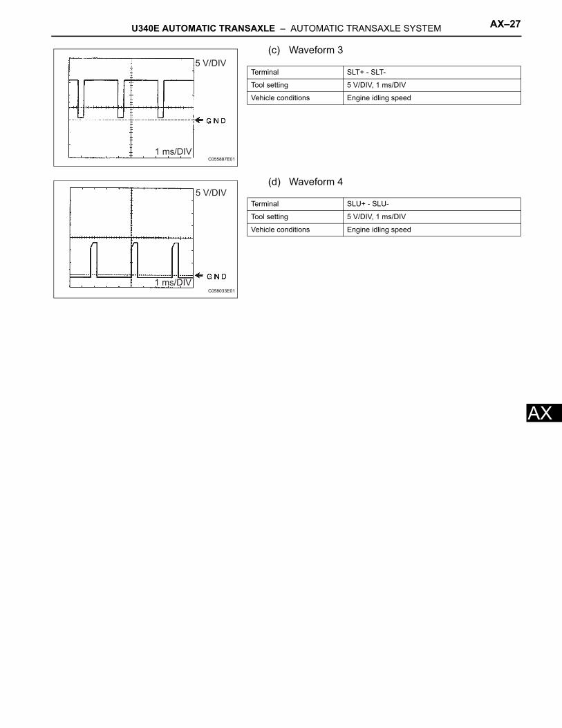
A(c) Waveform 3
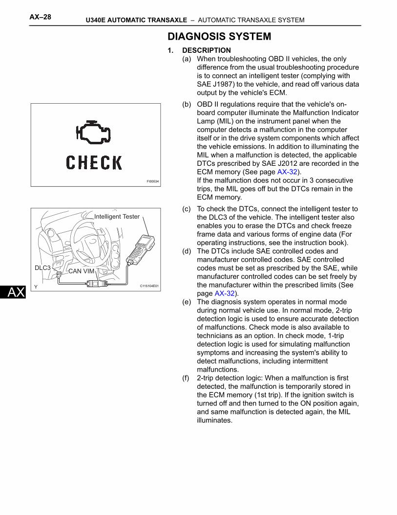
(d) Waveform 4
5 V/DIV
1 ms/DIVC055887E01
Terminal SLT+ - SLT-
Tool setting 5 V/DIV, 1 ms/DIV
Vehicle conditions Engine idling speed
5 V/DIV
1 ms/DIVC058033E01
Terminal SLU+ - SLU-
Tool setting 5 V/DIV, 1 ms/DIV
Vehicle conditions Engine idling speed
AX–28 U340E AUTOMATIC TRANSAXLE – AUTOMATIC TRANSAXLE SYSTEM
AX
DIAGNOSIS SYSTEM1. DESCRIPTION
(a) When troubleshooting OBD II vehicles, the only difference from the usual troubleshooting procedure is to connect an intelligent tester (complying with SAE J1987) to the vehicle, and read off various data output by the vehicle's ECM.
(b) OBD II regulations require that the vehicle's on-board computer illuminate the Malfunction Indicator Lamp (MIL) on the instrument panel when the computer detects a malfunction in the computer itself or in the drive system components which affect the vehicle emissions. In addition to illuminating the MIL when a malfunction is detected, the applicable DTCs prescribed by SAE J2012 are recorded in the ECM memory (See page AX-32). If the malfunction does not occur in 3 consecutive trips, the MIL goes off but the DTCs remain in the ECM memory.
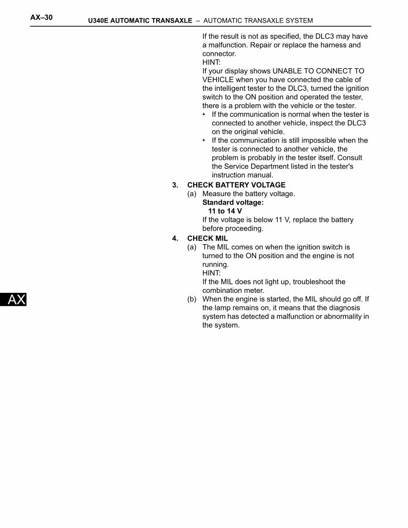
(c) To check the DTCs, connect the intelligent tester to the DLC3 of the vehicle. The intelligent tester also enables you to erase the DTCs and check freeze frame data and various forms of engine data (For operating instructions, see the instruction book).
(d) The DTCs include SAE controlled codes and manufacturer controlled codes. SAE controlled codes must be set as prescribed by the SAE, while manufacturer controlled codes can be set freely by the manufacturer within the prescribed limits (See page AX-32).
(e) The diagnosis system operates in normal mode during normal vehicle use. In normal mode, 2-trip detection logic is used to ensure accurate detection of malfunctions. Check mode is also available to technicians as an option. In check mode, 1-trip detection logic is used for simulating malfunction symptoms and increasing the system's ability to detect malfunctions, including intermittent malfunctions.
(f) 2-trip detection logic: When a malfunction is first detected, the malfunction is temporarily stored in the ECM memory (1st trip). If the ignition switch is turned off and then turned to the ON position again, and same malfunction is detected again, the MIL illuminates.
FI00534
Intelligent Tester
CAN VIMDLC3
C115104E01
U340E AUTOMATIC TRANSAXLE – AUTOMATIC TRANSAXLE SYSTEM AX–29
X
A(g) Freeze frame data records the engine conditions, such as fuel system, calculated load, engine coolant temperature, fuel trim, engine speed and vehicle speed when a malfunction is detected. When troubleshooting, freeze frame data can help determine if the vehicle was running or stopped, if the engine was warmed up or not, if the air/fuel ratio was lean or rich, and other data from the time the malfunction occurred.
(h) The intelligent tester records freeze frame data in five different instances: 1) 3 times before the DTC is set, 2) once when the DTC is set, and 3) once after the DTC is set. These data can be used to simulate the vehicle's conditions around the time when the malfunction occurred. The data may help find the cause of the malfunction, or judge if the DTC is being caused by a temporary malfunction or not.
2. INSPECT DLC3(a) The ECM uses ISO 15765-4 for communication.
The terminal arrangement of the DLC3 complies with SAE J1962 and matches the ISO 15765-4 format.
NOTICE:*: Before measuring the resistance, leave the vehicle as is for at least 1 minute and do not operate the ignition switch, any other switches or the doors.
0.5 0.50.5
(Seconds)
A092901E12
1 2 3 4 5 6 7 8
9 10 111213141516
CG
DLC3
SG SIL
BAT
CANH
CANL A082779E81
Symbols (Terminal No.) Terminal Description Condition Specified Condition
SIL (7) - SG (5) Bus "+" line During transmission Pulse generation
CG (4) - Body ground Chassis ground Always Below 1 Ω
SG (5) - Body ground Signal ground Always Below 1 Ω
BAT (16) - Body ground Battery positive Always 11 to 14 V
CANH (6) - CANL (14) CAN bus line Ignition switch OFF* 54 to 69 Ω
CANH (6) - CG (4) HIGH-level CAN bus line Ignition switch OFF* 200 Ω or higher
CANL (14) - CG (4) LOW-level CAN bus line Ignition switch OFF* 200 Ω or higher
CANH (6) - BAT (16) HIGH-level CAN bus line Ignition switch OFF* 6 kΩ or higher
CANL (14) - BAT (16) LOW-level CAN bus line Ignition switch OFF* 6 kΩ or higher
AX–30 U340E AUTOMATIC TRANSAXLE – AUTOMATIC TRANSAXLE SYSTEM
AX
If the result is not as specified, the DLC3 may have a malfunction. Repair or replace the harness and connector.HINT:If your display shows UNABLE TO CONNECT TO VEHICLE when you have connected the cable of the intelligent tester to the DLC3, turned the ignition switch to the ON position and operated the tester, there is a problem with the vehicle or the tester.• If the communication is normal when the tester is
connected to another vehicle, inspect the DLC3 on the original vehicle.
• If the communication is still impossible when the tester is connected to another vehicle, the problem is probably in the tester itself. Consult the Service Department listed in the tester's instruction manual.
3. CHECK BATTERY VOLTAGE(a) Measure the battery voltage.
Standard voltage:11 to 14 V
If the voltage is below 11 V, replace the battery before proceeding.
4. CHECK MIL(a) The MIL comes on when the ignition switch is
turned to the ON position and the engine is not running. HINT:If the MIL does not light up, troubleshoot the combination meter.
(b) When the engine is started, the MIL should go off. If the lamp remains on, it means that the diagnosis system has detected a malfunction or abnormality in the system.
U340E AUTOMATIC TRANSAXLE – AUTOMATIC TRANSAXLE SYSTEM AX–31
X
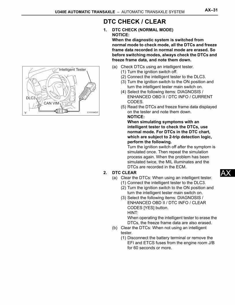
ADTC CHECK / CLEAR1. DTC CHECK (NORMAL MODE)
NOTICE:When the diagnostic system is switched from normal mode to check mode, all the DTCs and freeze frame data recorded in normal mode are erased. So before switching modes, always check the DTCs and freeze frame data, and note them down. (a) Check DTCs using an intelligent tester.
(1) Turn the ignition switch off.(2) Connect the intelligent tester to the DLC3.(3) Turn the ignition switch to the ON position and
turn the intelligent tester main switch on.(4) Select the following items: DIAGNOSIS /
ENHANCED OBD II / DTC INFO / CURRENT CODES.
(5) Read the DTCs and freeze frame data displayed on the tester and note them down.NOTICE:When simulating symptoms with an intelligent tester to check the DTCs, use normal mode. For DTCs in the DTC chart, which are subject to 2-trip detection logic, perform the following.Turn the ignition switch off after the symptom is simulated once. Then repeat the simulation process again. When the problem has been simulated twice, the MIL illuminates and the DTCs are recorded in the ECM.
2. DTC CLEAR(a) Clear the DTCs: When using an intelligent tester.
(1) Connect the intelligent tester to the DLC3.(2) Turn the ignition switch to the ON position and
turn the intelligent tester main switch on.(3) Select the following items: DIAGNOSIS /
ENHANCED OBD II / DTC INFO / CLEAR CODES [YES] button.HINT:When operating the intelligent tester to erase the DTCs, the freeze frame data are also erased.
(b) Clear the DTCs: When not using an intelligent tester.(1) Disconnect the battery terminal or remove the
EFI and ETCS fuses from the engine room J/B for 60 seconds or more.
Intelligent Tester
CAN VIM
DLC3
C115104E07
AX–32 U340E AUTOMATIC TRANSAXLE – AUTOMATIC TRANSAXLE SYSTEM
AX
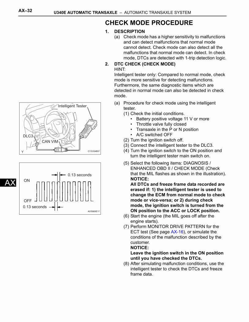
CHECK MODE PROCEDURE1. DESCRIPTION
(a) Check mode has a higher sensitivity to malfunctions and can detect malfunctions that normal mode cannot detect. Check mode can also detect all the malfunctions that normal mode can detect. In check mode, DTCs are detected with 1-trip detection logic.
2. DTC CHECK (CHECK MODE)HINT:Intelligent tester only: Compared to normal mode, check mode is more sensitive for detecting malfunctions. Furthermore, the same diagnostic items which are detected in normal mode can also be detected in check mode.(a) Procedure for check mode using the intelligent
tester. (1) Check the initial conditions.
• Battery positive voltage 11 V or more• Throttle valve fully closed• Transaxle in the P or N position• A/C switched OFF
(2) Turn the ignition switch off.(3) Connect the intelligent tester to the DLC3.(4) Turn the ignition switch to the ON position and
turn the intelligent tester main switch on.(5) Select the following items: DIAGNOSIS /
ENHANCED OBD II / CHECK MODE (Check that the MIL flashes as shown in the illustration).NOTICE:All DTCs and freeze frame data recorded are erased if: 1) the intelligent tester is used to change the ECM from normal mode to check mode or vice-versa; or 2) during check mode, the ignition switch is turned from the ON position to the ACC or LOCK position.
(6) Start the engine (the MIL goes off after the engine starts).
(7) Perform MONITOR DRIVE PATTERN for the ECT test (See page AX-16), or simulate the conditions of the malfunction described by the customer. NOTICE:Leave the ignition switch in the ON position until you have checked the DTCs.
(8) After simulating malfunction conditions, use the intelligent tester to check the DTCs and freeze frame data.
Intelligent Tester
CAN VIM
DLC3
C115104E07
ON
OFF
0.13 seconds
0.13 secondsA076900E17
U340E AUTOMATIC TRANSAXLE – AUTOMATIC TRANSAXLE SYSTEM AX–33
X
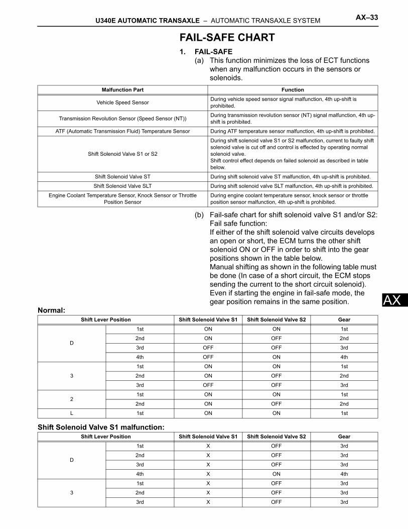
AFAIL-SAFE CHART1. FAIL-SAFE
(a) This function minimizes the loss of ECT functions when any malfunction occurs in the sensors or solenoids.
(b) Fail-safe chart for shift solenoid valve S1 and/or S2:Fail safe function:If either of the shift solenoid valve circuits develops an open or short, the ECM turns the other shift solenoid ON or OFF in order to shift into the gear positions shown in the table below. Manual shifting as shown in the following table must be done (In case of a short circuit, the ECM stops sending the current to the short circuit solenoid).Even if starting the engine in fail-safe mode, the gear position remains in the same position.
Normal:
Shift Solenoid Valve S1 malfunction:
Malfunction Part Function
Vehicle Speed Sensor During vehicle speed sensor signal malfunction, 4th up-shift is prohibited.
Transmission Revolution Sensor (Speed Sensor (NT)) During transmission revolution sensor (NT) signal malfunction, 4th up-shift is prohibited.
ATF (Automatic Transmission Fluid) Temperature Sensor During ATF temperature sensor malfunction, 4th up-shift is prohibited.
Shift Solenoid Valve S1 or S2
During shift solenoid valve S1 or S2 malfunction, current to faulty shift solenoid valve is cut off and control is effected by operating normal solenoid valve.Shift control effect depends on failed solenoid as described in table below.
Shift Solenoid Valve ST During shift solenoid valve ST malfunction, 4th up-shift is prohibited.
Shift Solenoid Valve SLT During shift solenoid valve SLT malfunction, 4th up-shift is prohibited.
Engine Coolant Temperature Sensor, Knock Sensor or Throttle Position Sensor
During engine coolant temperature sensor, knock sensor or throttle position sensor malfunction, 4th up-shift is prohibited.
Shift Lever Position Shift Solenoid Valve S1 Shift Solenoid Valve S2 Gear
D
1st ON ON 1st
2nd ON OFF 2nd
3rd OFF OFF 3rd
4th OFF ON 4th
3
1st ON ON 1st
2nd ON OFF 2nd
3rd OFF OFF 3rd
21st ON ON 1st
2nd ON OFF 2nd
L 1st ON ON 1st
Shift Lever Position Shift Solenoid Valve S1 Shift Solenoid Valve S2 Gear
D
1st X OFF 3rd
2nd X OFF 3rd
3rd X OFF 3rd
4th X ON 4th
3
1st X OFF 3rd
2nd X OFF 3rd
3rd X OFF 3rd
AX–34 U340E AUTOMATIC TRANSAXLE – AUTOMATIC TRANSAXLE SYSTEM
AX
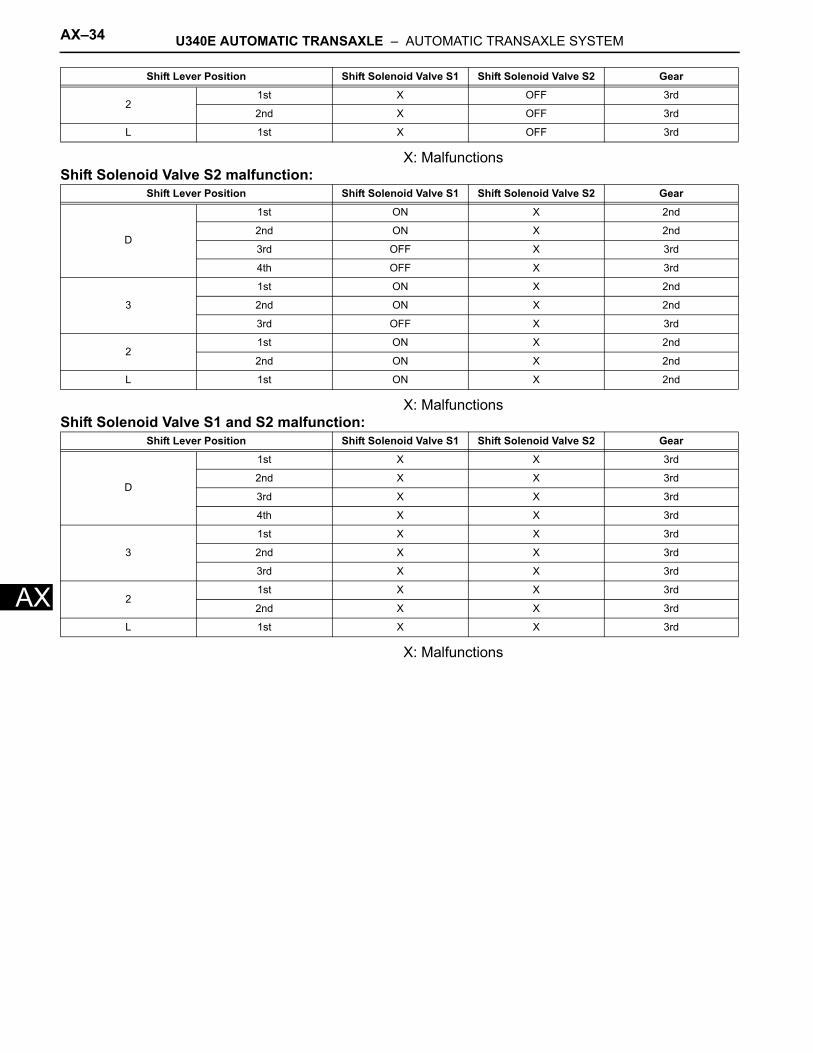
X: MalfunctionsShift Solenoid Valve S2 malfunction:
X: MalfunctionsShift Solenoid Valve S1 and S2 malfunction:
X: Malfunctions
21st X OFF 3rd
2nd X OFF 3rd
L 1st X OFF 3rd
Shift Lever Position Shift Solenoid Valve S1 Shift Solenoid Valve S2 Gear
Shift Lever Position Shift Solenoid Valve S1 Shift Solenoid Valve S2 Gear
D
1st ON X 2nd
2nd ON X 2nd
3rd OFF X 3rd
4th OFF X 3rd
3
1st ON X 2nd
2nd ON X 2nd
3rd OFF X 3rd
21st ON X 2nd
2nd ON X 2nd
L 1st ON X 2nd
Shift Lever Position Shift Solenoid Valve S1 Shift Solenoid Valve S2 Gear
D
1st X X 3rd
2nd X X 3rd
3rd X X 3rd
4th X X 3rd
3
1st X X 3rd
2nd X X 3rd
3rd X X 3rd
21st X X 3rd
2nd X X 3rd
L 1st X X 3rd
U340E AUTOMATIC TRANSAXLE – AUTOMATIC TRANSAXLE SYSTEM AX–35
X
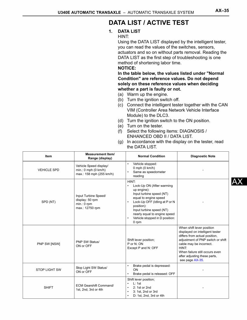
ADATA LIST / ACTIVE TEST1. DATA LIST
HINT:Using the DATA LIST displayed by the intelligent tester, you can read the values of the switches, sensors, actuators and so on without parts removal. Reading the DATA LIST as the first step of troubleshooting is one method of shortening labor time.NOTICE:In the table below, the values listed under "Normal Condition" are reference values. Do not depend solely on these reference values when deciding whether a part is faulty or not.(a) Warm up the engine.(b) Turn the ignition switch off.(c) Connect the intelligent tester together with the CAN
VIM (Controller Area Network Vehicle Interface Module) to the DLC3.
(d) Turn the ignition switch to the ON position.(e) Turn on the tester.(f) Select the following items: DIAGNOSIS /
ENHANCED OBD II / DATA LIST.(g) In accordance with the display on the tester, read
the DATA LIST.
Item Measurement Item/Range (display) Normal Condition Diagnostic Note
VEHICLE SPDVehicle Speed display/min.: 0 mph (0 km/h)max.: 158 mph (255 km/h)
• Vehicle stopped:0 mph (0 km/h)
• Same as speedometer reading
-
SPD (NT)
Input Turbine Speed/display: 50 rpmmin.: 0 rpmmax.: 12750 rpm
HINT:• Lock-Up ON (After warming
up engine):Input turbine speed (NT) equal to engine speed
• Lock-Up OFF (Idling at P or N position): Input turbine speed (NT) nearly equal to engine speed
• Vehicle stopped in D position: 0 rpm
-
PNP SW [NSW] PNP SW Status/ON or OFF
Shift lever position;P or N: ONExcept P and N: OFF
When shift lever position displayed on intelligent tester differs from actual position, adjustment of PNP switch or shift cable may be incorrect.HINT:When failure still occurs even after adjusting these parts, see page AX-35.
STOP LIGHT SW Stop Light SW Status/ON or OFF
• Brake pedal is depressed: ON
• Brake pedal is released: OFF-
SHIFT ECM Gearshift Command/1st, 2nd, 3rd or 4th
Shift lever position;• L: 1st• 2: 1st or 2nd• 3: 1st, 2nd or 3rd• D: 1st, 2nd, 3rd or 4th
-
AX–36 U340E AUTOMATIC TRANSAXLE – AUTOMATIC TRANSAXLE SYSTEM
AX
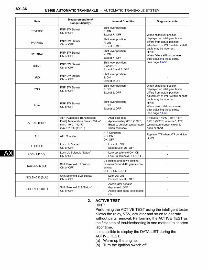
2. ACTIVE TESTHINT:Performing the ACTIVE TEST using the intelligent tester allows the relay, VSV, actuator and so on to operate without parts removal. Performing the ACTIVE TEST as the first step of troubleshooting is one method to shorten labor time.It is possible to display the DATA LIST during the ACTIVE TEST.(a) Warm up the engine.(b) Turn the ignition switch off.
REVERSE PNP SW Status/ON or OFF
Shift lever position;R: ONExcept R: OFF When shift lever position
displayed on intelligent tester differs from actual position, adjustment of PNP switch or shift cable may be incorrect.HINT:When failure still occurs even after adjusting these parts, see page AX-35.
PARKING PNP SW Status/ON or OFF
Shift lever position;P: ONExcept P: OFF
NEUTRAL PNP SW Status/ON or OFF
Shift lever position;N: ONExcept N: OFF
DRIVE PNP SW Status/ON or OFF
Shift lever position;D or 3: ONExcept D and 3: OFF
3RD PNP SW Status/ON or OFF
Shift lever position;3: ONExcept 3: OFF
-
2ND PNP SW Status/ON or OFF
Shift lever position;2: ONExcept 2: OFF
When shift lever position displayed on intelligent tester differs from actual position, adjustment of PNP switch or shift cable may be incorrect.HINT:When failure still occurs even after adjusting these parts, see page AX-35.
LOW PNP SW Status/ON or OFF
Shift lever position;L: ONExcept L: OFF
A/T OIL TEMP1
ATF (Automatic Transmission Fluid) Temperature Sensor Value/min.: -40°C (-40°F)max.: 215°C (419°F)
• After Stall Test; Approximately 80°C (176°F)
• Equal to ambient temperature when cold soak
If value is "-40°C (-40°F)" or " 150°C (302°F) or more ", ATF temperature sensor circuit is open or short.
ATF ATF ConditionATF Condition;NG: ONOK: OFF
Replace ATF when ATF condition is ON.
LOCK UP Lock Up Status/ON or OFF
• Lock Up: ON• Except Lock Up: OFF -
LOCK UP SOL Lock Up Solenoid Status/ON or OFF
• Lock up solenoid ON: ON• Lock up solenoid OFF: OFF -
SOLENOID (ST) Shift Solenoid ST Status/ON or OFF
Up-shifting and down-shifting between 3rd and 4th gears while driving:OFF → ON → OFF
-
SOLENOID (SLU) Shift Solenoid SLU Status/ON or OFF
• Lock Up: ON• Except Lock Up: OFF -
SOLENOID (SLT) Shift Solenoid SLT Status/ON or OFF
• Accelerator pedal is depressed: OFF
• Accelerator pedal is released: ON
-
Item Measurement Item/Range (display) Normal Condition Diagnostic Note
U340E AUTOMATIC TRANSAXLE – AUTOMATIC TRANSAXLE SYSTEM AX–37
X
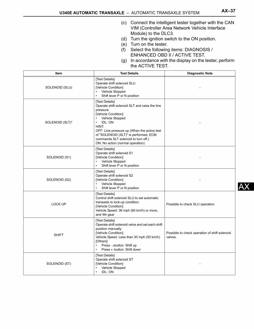
A(c) Connect the intelligent tester together with the CAN VIM (Controller Area Network Vehicle Interface Module) to the DLC3.
(d) Turn the ignition switch to the ON position.(e) Turn on the tester.(f) Select the following items: DIAGNOSIS /
ENHANCED OBD II / ACTIVE TEST.(g) In accordance with the display on the tester, perform
the ACTIVE TEST.Item Test Details Diagnostic Note
SOLENOID (SLU)
[Test Details] Operate shift solenoid SLU[Vehicle Condition]• Vehicle Stopped• Shift lever P or N position
-
SOLENOID (SLT)*
[Test Details] Operate shift solenoid SLT and raise the line pressure.[Vehicle Condition]• Vehicle Stopped• IDL: ONHINT:OFF: Line pressure up (When the active test of "SOLENOID (SLT)" is performed, ECM commands SLT solenoid to turn off.)ON: No action (normal operation)
-
SOLENOID (S1)
[Test Details] Operate shift solenoid S1[Vehicle Condition]• Vehicle Stopped• Shift lever P or N position
-
SOLENOID (S2)
[Test Details] Operate shift solenoid S2[Vehicle Condition]• Vehicle Stopped• Shift lever P or N position
-
LOCK UP
[Test Details] Control shift solenoid SLU to set automatic transaxle to lock-up condition.[Vehicle Condition]Vehicle Speed: 36 mph (60 km/h) or more, and 4th gear
Possible to check SLU operation.
SHIFT
[Test Details] Operate shift solenoid valve and set each shift position manually. [Vehicle Condition] Vehicle Speed: Less than 30 mph (50 km/h)[Others]• Press →button: Shift up• Press ←button: Shift down
Possible to check operation of shift solenoid valves.
SOLENOID (ST)
[Test Details] Operate shift solenoid ST[Vehicle Condition]• Vehicle Stopped• IDL: ON
-
AX–38 U340E AUTOMATIC TRANSAXLE – AUTOMATIC TRANSAXLE SYSTEM
AX
*: SOLENOID (SLT) in the ACTIVE TEST is performed to check the line pressure changes by connecting SST to the automatic transaxle, which is used in the HYDRAULIC TEST (See page AX-13) as well.HINT:The pressure values in ACTIVE TEST and HYDRAULIC TEST are different from each other.
U340E AUTOMATIC TRANSAXLE – AUTOMATIC TRANSAXLE SYSTEM AX–39
X
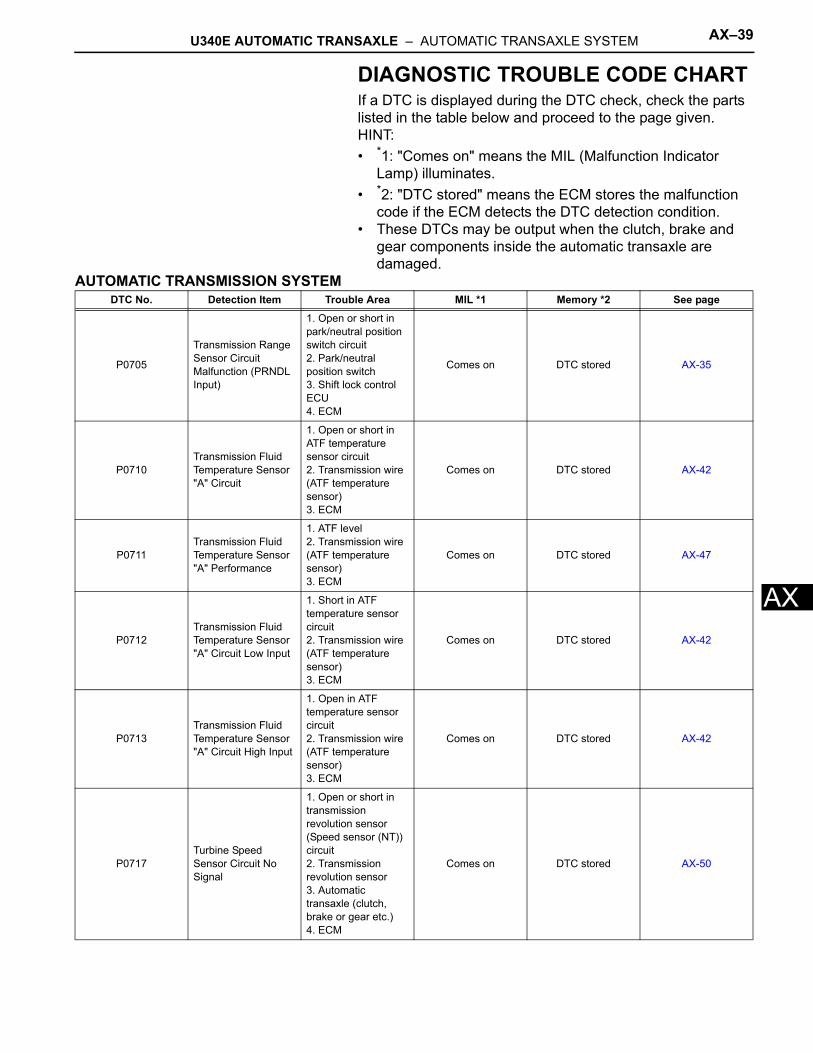
ADIAGNOSTIC TROUBLE CODE CHARTIf a DTC is displayed during the DTC check, check the parts listed in the table below and proceed to the page given.HINT:• *1: "Comes on" means the MIL (Malfunction Indicator
Lamp) illuminates.• *2: "DTC stored" means the ECM stores the malfunction
code if the ECM detects the DTC detection condition.• These DTCs may be output when the clutch, brake and
gear components inside the automatic transaxle are damaged.
AUTOMATIC TRANSMISSION SYSTEMDTC No. Detection Item Trouble Area MIL *1 Memory *2 See page
P0705
Transmission Range Sensor Circuit Malfunction (PRNDL Input)
1. Open or short in park/neutral position switch circuit2. Park/neutral position switch3. Shift lock control ECU4. ECM
Comes on DTC stored AX-35
P0710Transmission Fluid Temperature Sensor "A" Circuit
1. Open or short in ATF temperature sensor circuit2. Transmission wire (ATF temperature sensor)3. ECM
Comes on DTC stored AX-42
P0711Transmission Fluid Temperature Sensor "A" Performance
1. ATF level2. Transmission wire (ATF temperature sensor)3. ECM
Comes on DTC stored AX-47
P0712Transmission Fluid Temperature Sensor "A" Circuit Low Input
1. Short in ATF temperature sensor circuit2. Transmission wire (ATF temperature sensor)3. ECM
Comes on DTC stored AX-42
P0713Transmission Fluid Temperature Sensor "A" Circuit High Input
1. Open in ATF temperature sensor circuit2. Transmission wire (ATF temperature sensor)3. ECM
Comes on DTC stored AX-42
P0717Turbine Speed Sensor Circuit No Signal
1. Open or short in transmission revolution sensor (Speed sensor (NT)) circuit2. Transmission revolution sensor3. Automatic transaxle (clutch, brake or gear etc.)4. ECM
Comes on DTC stored AX-50

AX–40 U340E AUTOMATIC TRANSAXLE – AUTOMATIC TRANSAXLE SYSTEM
AX
P0751Shift Solenoid "A" Performance (Shift Solenoid Valve S1)
1. Shift solenoid valve S1 remains open or closed2. Valve body is blocked3. Shift solenoid valve S14. Automatic transaxle (clutch, brake or gear etc.)5. ECM
Comes on DTC stored AX-53
P0756Shift Solenoid "B" Performance (Shift Solenoid Valve S2)
1. Shift solenoid valve S2 remains open or closed2. Valve body is blocked3. Shift solenoid valve S24. Automatic transaxle (clutch, brake or gear etc.)5. ECM
Comes on DTC stored AX-58
P0787Shift / Timing Solenoid Low (Shift Solenoid Valve ST)
1. Short in shift solenoid valve ST circuit2. Shift solenoid valve ST3. ECM
Comes on DTC stored AX-63
P0788Shift / Timing Solenoid High (Shift Solenoid Valve ST)
1. Open in shift solenoid valve ST circuit2. Shift solenoid valve ST3. ECM
Comes on DTC stored AX-63
P0973
Shift Solenoid "A" Control Circuit Low (Shift Solenoid Valve S1)
1. Short in shift solenoid valve S1 circuit2. Shift solenoid valve S13. ECM
Comes on DTC stored AX-67
P0974
Shift Solenoid "A" Control Circuit High (Shift Solenoid Valve S1)
1. Open in shift solenoid valve S1 circuit2. Shift solenoid valve S13. ECM
Comes on DTC stored AX-67
P0976
Shift Solenoid "B" Control Circuit Low (Shift Solenoid Valve S2)
1. Short in shift solenoid valve S2 circuit2. Shift solenoid valve S23. ECM
Comes on DTC stored AX-71
P0977
Shift Solenoid "B" Control Circuit High (Shift Solenoid Valve S2)
1. Open in shift solenoid valve S2 circuit2. Shift solenoid valve S23. ECM
Comes on DTC stored AX-71
DTC No. Detection Item Trouble Area MIL *1 Memory *2 See page
U340E AUTOMATIC TRANSAXLE – AUTOMATIC TRANSAXLE SYSTEM AX–41
X
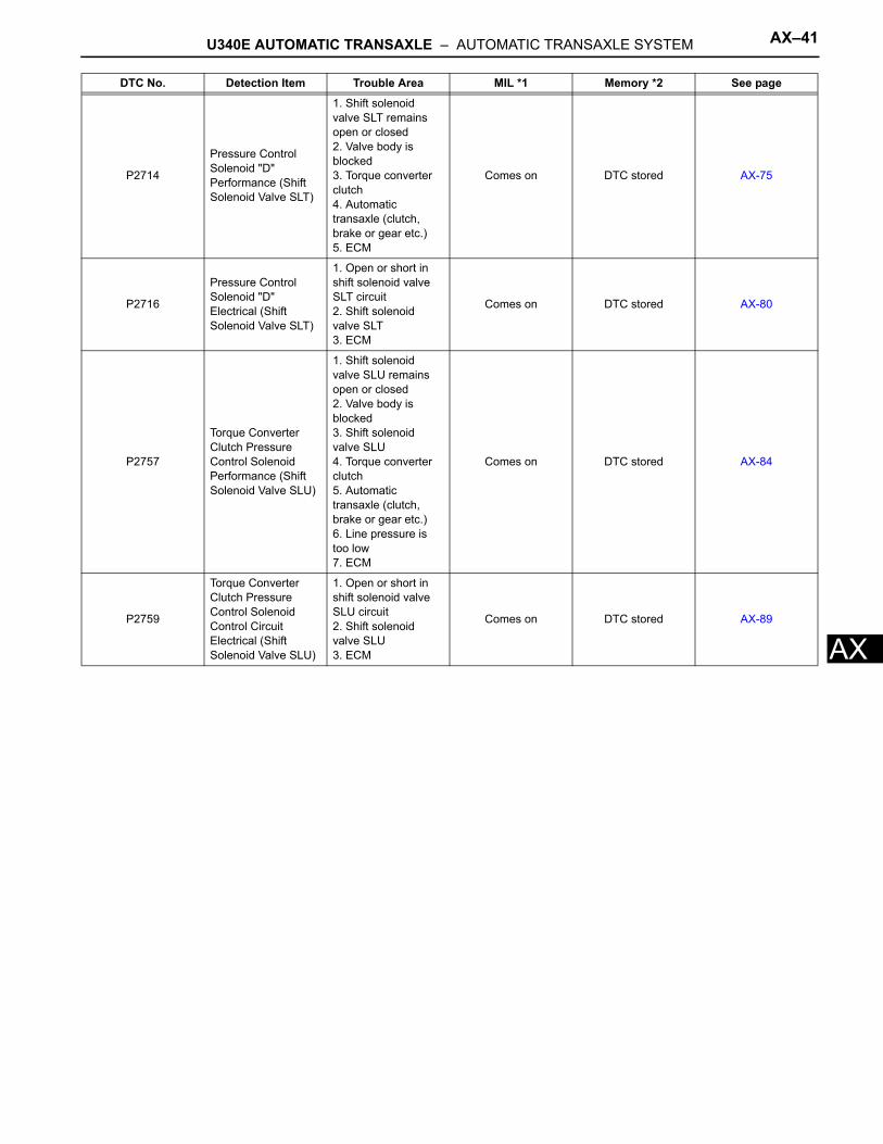
AP2714
Pressure Control Solenoid "D" Performance (Shift Solenoid Valve SLT)
1. Shift solenoid valve SLT remains open or closed2. Valve body is blocked3. Torque converter clutch4. Automatic transaxle (clutch, brake or gear etc.)5. ECM
Comes on DTC stored AX-75
P2716
Pressure Control Solenoid "D" Electrical (Shift Solenoid Valve SLT)
1. Open or short in shift solenoid valve SLT circuit2. Shift solenoid valve SLT3. ECM
Comes on DTC stored AX-80
P2757
Torque Converter Clutch Pressure Control Solenoid Performance (Shift Solenoid Valve SLU)
1. Shift solenoid valve SLU remains open or closed2. Valve body is blocked3. Shift solenoid valve SLU4. Torque converter clutch5. Automatic transaxle (clutch, brake or gear etc.)6. Line pressure is too low7. ECM
Comes on DTC stored AX-84
P2759
Torque Converter Clutch Pressure Control Solenoid Control Circuit Electrical (Shift Solenoid Valve SLU)
1. Open or short in shift solenoid valve SLU circuit2. Shift solenoid valve SLU3. ECM
Comes on DTC stored AX-89
DTC No. Detection Item Trouble Area MIL *1 Memory *2 See page
AX–42 U340E AUTOMATIC TRANSAXLE – AUTOMATIC TRANSAXLE SYSTEM
AX
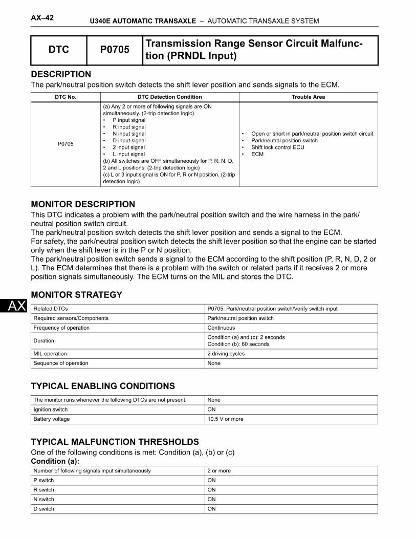
DESCRIPTIONThe park/neutral position switch detects the shift lever position and sends signals to the ECM.
MONITOR DESCRIPTIONThis DTC indicates a problem with the park/neutral position switch and the wire harness in the park/neutral position switch circuit.The park/neutral position switch detects the shift lever position and sends a signal to the ECM.For safety, the park/neutral position switch detects the shift lever position so that the engine can be started only when the shift lever is in the P or N position.The park/neutral position switch sends a signal to the ECM according to the shift position (P, R, N, D, 2 or L). The ECM determines that there is a problem with the switch or related parts if it receives 2 or more position signals simultaneously. The ECM turns on the MIL and stores the DTC.
MONITOR STRATEGY
TYPICAL ENABLING CONDITIONS
TYPICAL MALFUNCTION THRESHOLDSOne of the following conditions is met: Condition (a), (b) or (c)Condition (a):
DTC P0705 Transmission Range Sensor Circuit Malfunc-tion (PRNDL Input)
DTC No. DTC Detection Condition Trouble Area
P0705
(a) Any 2 or more of following signals are ON simultaneously. (2-trip detection logic)• P input signal• R input signal• N input signal• D input signal• 2 input signal• L input signal(b) All switches are OFF simultaneously for P, R, N, D, 2 and L positions. (2-trip detection logic)(c) L or 3 input signal is ON for P, R or N position. (2-trip detection logic)
• Open or short in park/neutral position switch circuit• Park/neutral position switch• Shift lock control ECU• ECM
Related DTCs P0705: Park/neutral position switch/Verify switch input
Required sensors/Components Park/neutral position switch
Frequency of operation Continuous
Duration Condition (a) and (c): 2 secondsCondition (b): 60 seconds
MIL operation 2 driving cycles
Sequence of operation None
The monitor runs whenever the following DTCs are not present. None
Ignition switch ON
Battery voltage 10.5 V or more
Number of following signals input simultaneously 2 or more
P switch ON
R switch ON
N switch ON
D switch ON
U340E AUTOMATIC TRANSAXLE – AUTOMATIC TRANSAXLE SYSTEM AX–43
X
ACondition (b):All of the following conditions are met.
Condition (c):When shift lever is in P, R or N position, either of following conditions is met.
COMPONENT OPERATING RANGE
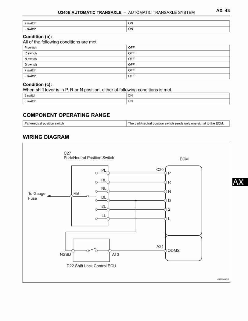
WIRING DIAGRAM
2 switch ON
L switch ON
P switch OFF
R switch OFF
N switch OFF
D switch OFF
2 switch OFF
L switch OFF
3 switch ON
L switch ON
Park/neutral position switch The park/neutral position switch sends only one signal to the ECM.
Park/Neutral Position Switch ECM
PL
RL
NL
DL
2L
LL
P
R
N
D
2
L
NSSD AT3
D22 Shift Lock Control ECU
ODMS
RBTo Gauge
Fuse
C27
C20
A21
C117646E02
AX–44 U340E AUTOMATIC TRANSAXLE – AUTOMATIC TRANSAXLE SYSTEM
AX
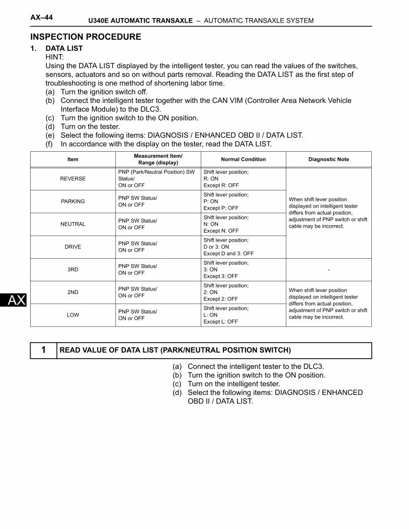
INSPECTION PROCEDURE1. DATA LIST
HINT:Using the DATA LIST displayed by the intelligent tester, you can read the values of the switches, sensors, actuators and so on without parts removal. Reading the DATA LIST as the first step of troubleshooting is one method of shortening labor time.(a) Turn the ignition switch off.(b) Connect the intelligent tester together with the CAN VIM (Controller Area Network Vehicle
Interface Module) to the DLC3.(c) Turn the ignition switch to the ON position.(d) Turn on the tester.(e) Select the following items: DIAGNOSIS / ENHANCED OBD II / DATA LIST.(f) In accordance with the display on the tester, read the DATA LIST.
(a) Connect the intelligent tester to the DLC3.(b) Turn the ignition switch to the ON position.(c) Turn on the intelligent tester.(d) Select the following items: DIAGNOSIS / ENHANCED
OBD II / DATA LIST.
Item Measurement Item/Range (display) Normal Condition Diagnostic Note
REVERSEPNP (Park/Neutral Position) SW Status/ON or OFF
Shift lever position;R: ONExcept R: OFF
When shift lever position displayed on intelligent tester differs from actual position, adjustment of PNP switch or shift cable may be incorrect.
PARKING PNP SW Status/ON or OFF
Shift lever position;P: ONExcept P: OFF
NEUTRAL PNP SW Status/ON or OFF
Shift lever position;N: ONExcept N: OFF
DRIVE PNP SW Status/ON or OFF
Shift lever position;D or 3: ONExcept D and 3: OFF
3RD PNP SW Status/ON or OFF
Shift lever position;3: ONExcept 3: OFF
-
2ND PNP SW Status/ON or OFF
Shift lever position;2: ONExcept 2: OFF
When shift lever position displayed on intelligent tester differs from actual position, adjustment of PNP switch or shift cable may be incorrect.LOW PNP SW Status/
ON or OFF
Shift lever position;L: ONExcept L: OFF
1 READ VALUE OF DATA LIST (PARK/NEUTRAL POSITION SWITCH)
U340E AUTOMATIC TRANSAXLE – AUTOMATIC TRANSAXLE SYSTEM AX–45
X
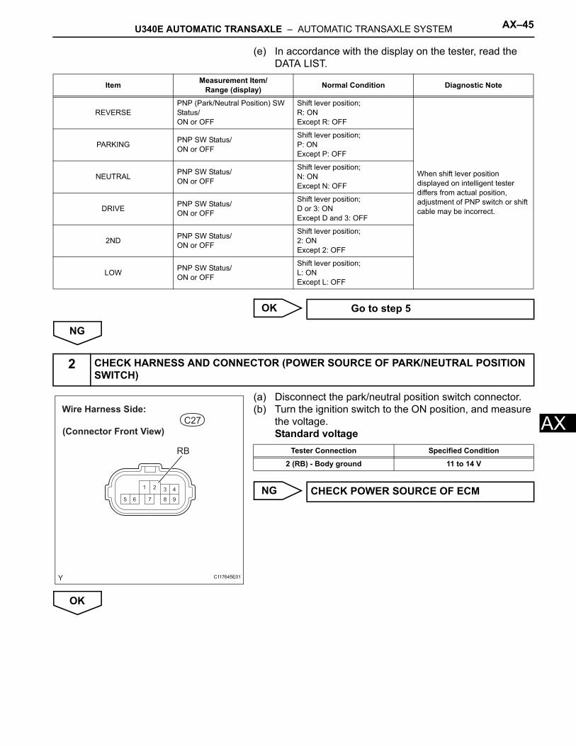
A(e) In accordance with the display on the tester, read the DATA LIST.
OK
NG
(a) Disconnect the park/neutral position switch connector.(b) Turn the ignition switch to the ON position, and measure
the voltage.Standard voltage
NG
OK
Item Measurement Item/Range (display) Normal Condition Diagnostic Note
REVERSEPNP (Park/Neutral Position) SW Status/ON or OFF
Shift lever position;R: ONExcept R: OFF
When shift lever position displayed on intelligent tester differs from actual position, adjustment of PNP switch or shift cable may be incorrect.
PARKING PNP SW Status/ON or OFF
Shift lever position;P: ONExcept P: OFF
NEUTRAL PNP SW Status/ON or OFF
Shift lever position;N: ONExcept N: OFF
DRIVE PNP SW Status/ON or OFF
Shift lever position;D or 3: ONExcept D and 3: OFF
2ND PNP SW Status/ON or OFF
Shift lever position;2: ONExcept 2: OFF
LOW PNP SW Status/ON or OFF
Shift lever position;L: ONExcept L: OFF
Go to step 5
2 CHECK HARNESS AND CONNECTOR (POWER SOURCE OF PARK/NEUTRAL POSITION SWITCH)
1 2 3 4
98765
C27
(Connector Front View)
Wire Harness Side:
RB
C117645E01
Tester Connection Specified Condition
2 (RB) - Body ground 11 to 14 V
CHECK POWER SOURCE OF ECM
AX–46 U340E AUTOMATIC TRANSAXLE – AUTOMATIC TRANSAXLE SYSTEM
AX
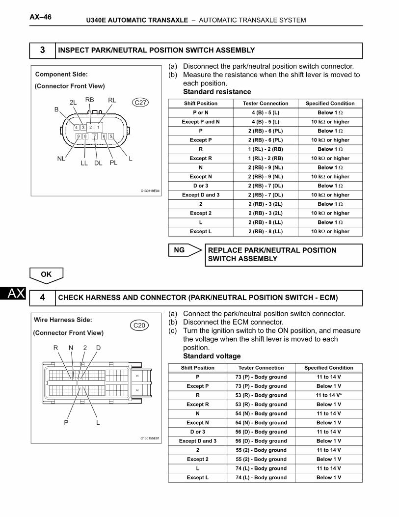
(a) Disconnect the park/neutral position switch connector.(b) Measure the resistance when the shift lever is moved to
each position.Standard resistance
NG
OK
(a) Connect the park/neutral position switch connector.(b) Disconnect the ECM connector.(c) Turn the ignition switch to the ON position, and measure
the voltage when the shift lever is moved to each position.Standard voltage
3 INSPECT PARK/NEUTRAL POSITION SWITCH ASSEMBLY
1234
9 8 7 6 5
Component Side:
(Connector Front View)
C27RLRB2L
NLLL DL PL
B
L
C130119E04
Shift Position Tester Connection Specified Condition
P or N 4 (B) - 5 (L) Below 1 Ω
Except P and N 4 (B) - 5 (L) 10 kΩ or higher
P 2 (RB) - 6 (PL) Below 1 Ω
Except P 2 (RB) - 6 (PL) 10 kΩ or higher
R 1 (RL) - 2 (RB) Below 1 Ω
Except R 1 (RL) - 2 (RB) 10 kΩ or higher
N 2 (RB) - 9 (NL) Below 1 Ω
Except N 2 (RB) - 9 (NL) 10 kΩ or higher
D or 3 2 (RB) - 7 (DL) Below 1 Ω
Except D and 3 2 (RB) - 7 (DL) 10 kΩ or higher
2 2 (RB) - 3 (2L) Below 1 Ω
Except 2 2 (RB) - 3 (2L) 10 kΩ or higher
L 2 (RB) - 8 (LL) Below 1 Ω
Except L 2 (RB) - 8 (LL) 10 kΩ or higher
REPLACE PARK/NEUTRAL POSITION SWITCH ASSEMBLY
4 CHECK HARNESS AND CONNECTOR (PARK/NEUTRAL POSITION SWITCH - ECM)
C20Wire Harness Side:
(Connector Front View)
LP
R 2 DN
C130155E01
Shift Position Tester Connection Specified Condition
P 73 (P) - Body ground 11 to 14 V
Except P 73 (P) - Body ground Below 1 V
R 53 (R) - Body ground 11 to 14 V*
Except R 53 (R) - Body ground Below 1 V
N 54 (N) - Body ground 11 to 14 V
Except N 54 (N) - Body ground Below 1 V
D or 3 56 (D) - Body ground 11 to 14 V
Except D and 3 56 (D) - Body ground Below 1 V
2 55 (2) - Body ground 11 to 14 V
Except 2 55 (2) - Body ground Below 1 V
L 74 (L) - Body ground 11 to 14 V
Except L 74 (L) - Body ground Below 1 V
U340E AUTOMATIC TRANSAXLE – AUTOMATIC TRANSAXLE SYSTEM AX–47
X
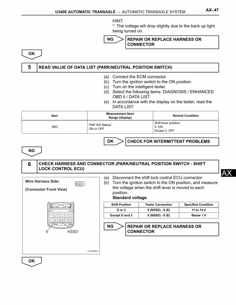
AHINT:*: The voltage will drop slightly due to the back up light being turned on.
NG
OK
(a) Connect the ECM connector.(b) Turn the ignition switch to the ON position.(c) Turn on the intelligent tester.(d) Select the following items: DIAGNOSIS / ENHANCED
OBD II / DATA LIST.(e) In accordance with the display on the tester, read the
DATA LIST.
OK
NG
(a) Disconnect the shift lock control ECU connector.(b) Turn the ignition switch to the ON position, and measure
the voltage when the shift lever is moved to each position.Standard voltage
NG
OK
REPAIR OR REPLACE HARNESS OR CONNECTOR
5 READ VALUE OF DATA LIST (PARK/NEUTRAL POSITION SWITCH)
Item Measurement Item/ Range (display) Normal Condition
3RD PNP SW Status/ON or OFF
Shift lever position;3: ONExcept 3: OFF
CHECK FOR INTERMITTENT PROBLEMS
6 CHECK HARNESS AND CONNECTOR (PARK/NEUTRAL POSITION SWITCH - SHIFT LOCK CONTROL ECU)
D22
(Connector Front View)
Wire Harness Side:
E NSSD
C117647E01
Shift Position Tester Connection Specified Condition
D or 3 9 (NSSD) - 8 (E) 11 to 14 V
Except D and 3 9 (NSSD) - 8 (E) Below 1 V
REPAIR OR REPLACE HARNESS OR CONNECTOR
AX–48 U340E AUTOMATIC TRANSAXLE – AUTOMATIC TRANSAXLE SYSTEM
AX
(a) Disconnect the shift lock control ECU connector.(b) Measure the resistance when the shift lever is moved to
each position.Standard resistance
NG
OK
(a) Connect the shift lock control ECU connector.(b) Disconnect the ECM connectors.(c) Turn the ignition switch to the ON position, and measure
the voltage.Standard voltage
NG
OK
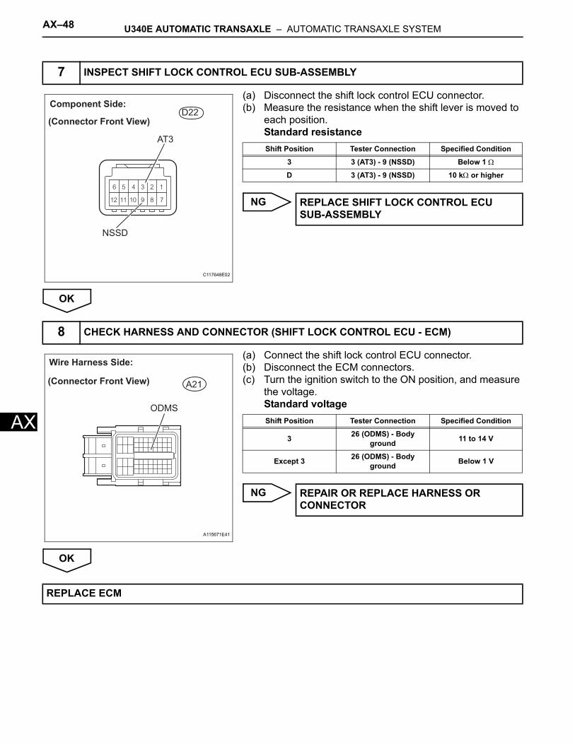
7 INSPECT SHIFT LOCK CONTROL ECU SUB-ASSEMBLY
D22(Connector Front View)
Component Side:
NSSD
AT3
C117648E02
Shift Position Tester Connection Specified Condition
3 3 (AT3) - 9 (NSSD) Below 1 Ω
D 3 (AT3) - 9 (NSSD) 10 kΩ or higher
REPLACE SHIFT LOCK CONTROL ECU SUB-ASSEMBLY
8 CHECK HARNESS AND CONNECTOR (SHIFT LOCK CONTROL ECU - ECM)
A21
ODMS
Wire Harness Side:
(Connector Front View)
A115671E41
Shift Position Tester Connection Specified Condition
3 26 (ODMS) - Body ground 11 to 14 V
Except 3 26 (ODMS) - Body ground Below 1 V
REPAIR OR REPLACE HARNESS OR CONNECTOR
REPLACE ECM
U340E AUTOMATIC TRANSAXLE – AUTOMATIC TRANSAXLE SYSTEM AX–49
X
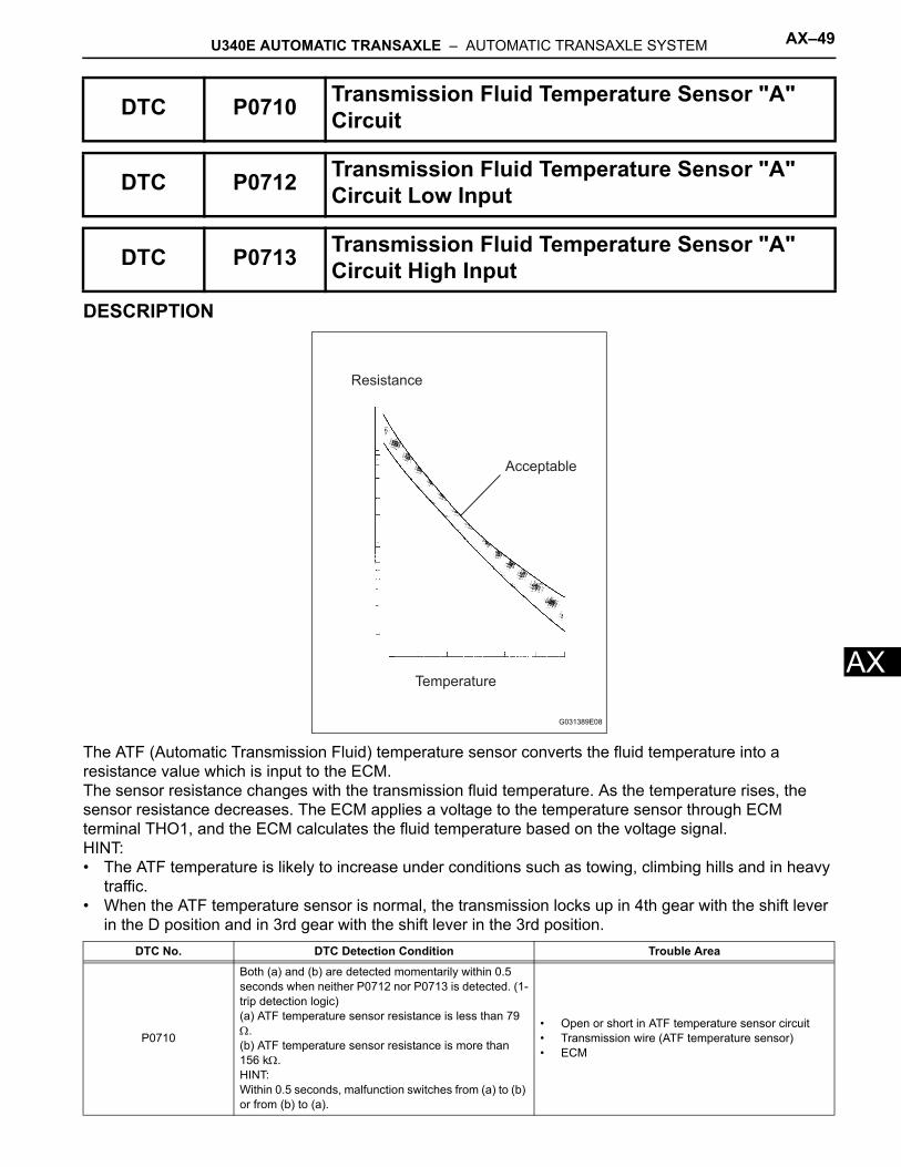
ADESCRIPTION
The ATF (Automatic Transmission Fluid) temperature sensor converts the fluid temperature into a resistance value which is input to the ECM.The sensor resistance changes with the transmission fluid temperature. As the temperature rises, the sensor resistance decreases. The ECM applies a voltage to the temperature sensor through ECM terminal THO1, and the ECM calculates the fluid temperature based on the voltage signal.HINT:• The ATF temperature is likely to increase under conditions such as towing, climbing hills and in heavy
traffic.• When the ATF temperature sensor is normal, the transmission locks up in 4th gear with the shift lever
in the D position and in 3rd gear with the shift lever in the 3rd position.
DTC P0710 Transmission Fluid Temperature Sensor "A" Circuit
DTC P0712 Transmission Fluid Temperature Sensor "A" Circuit Low Input
DTC P0713 Transmission Fluid Temperature Sensor "A" Circuit High Input
DTC No. DTC Detection Condition Trouble Area
P0710
Both (a) and (b) are detected momentarily within 0.5 seconds when neither P0712 nor P0713 is detected. (1-trip detection logic)(a) ATF temperature sensor resistance is less than 79 Ω.(b) ATF temperature sensor resistance is more than 156 kΩ.HINT:Within 0.5 seconds, malfunction switches from (a) to (b) or from (b) to (a).
• Open or short in ATF temperature sensor circuit• Transmission wire (ATF temperature sensor)• ECM
Acceptable
Temperature
Resistance
G031389E08
AX–50 U340E AUTOMATIC TRANSAXLE – AUTOMATIC TRANSAXLE SYSTEM
AX
MONITOR DESCRIPTIONThe ATF temperature sensor converts the ATF temperature to an electrical resistance value. Based on the resistance, the ECM determines the ATF temperature and detects opens or shorts in the ATF temperature circuit. If the resistance value of the ATF temperature is less than 79 Ω*1 or more than 156 kΩ*2, the ECM interprets this as a fault in the ATF sensor or wiring. The ECM turns on the MIL and stores the DTC.*1: 150°C (302°F) or more is indicated regardless of the actual ATF temperature.*2: -40°C (-40°F) is indicated regardless of the actual ATF temperature.HINT:The ATF temperature can be checked on the intelligent tester display.
MONITOR STRATEGY
*1: Transmission Fluid Temperature
TYPICAL ENABLING CONDITIONSP0710: Range check (Fluttering)
P0712: Range check (Low resistance)
P0713: Range check (High resistance)
TYPICAL MALFUNCTION THRESHOLDSP0710: Range check (Fluttering)
P0712: Range check (Low resistance)
P0712 ATF temperature sensor resistance is less than 79 Ω for 0.5 seconds or more. (1-trip detection logic)
• Short in ATF temperature sensor circuit• Transmission wire (ATF temperature sensor)• ECM
P0713
Following condition continues for 0.5 seconds or more. (1-trip detection logic)ATF temperature sensor resistance is more than 156 kΩ after 15 minutes or more after starting engine.
• Open in ATF temperature sensor circuit• Transmission wire (ATF temperature sensor)• ECM
Related DTCsP0710: ATF temperature sensor/Range check (Fluttering)P0712: ATF temperature sensor/Range check (Low resistance)P0713: ATF temperature sensor/Range check (High resistance)
Required sensors/Components ATF temperature sensor (TFT*1 sensor)
Frequency of operation Continuous
Duration 0.5 seconds
MIL operation Immediate
Sequence of operation None
The monitor runs whenever the following DTCs are not present. None
The typical enabling conditions are not available. -
The monitor runs whenever the following DTCs are not present. None
The typical enabling conditions are not available. -
The monitor runs whenever the following DTCs are not present. None
Time after engine start 15 minutes or more
ATF temperature sensor (TFT sensor) resistanceLess than 79 ΩorMore than 156 kΩ
ATF temperature sensor (TFT sensor) resistance Less than 79 Ω
DTC No. DTC Detection Condition Trouble Area
U340E AUTOMATIC TRANSAXLE – AUTOMATIC TRANSAXLE SYSTEM AX–51
X
AP0713: Range check (High resistance)
COMPONENT OPERATING RANGE
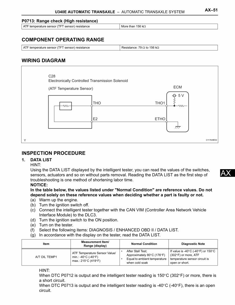
WIRING DIAGRAM
INSPECTION PROCEDURE1. DATA LIST
HINT:Using the DATA LIST displayed by the intelligent tester, you can read the values of the switches, sensors, actuators and so on without parts removal. Reading the DATA LIST as the first step of troubleshooting is one method of shortening labor time.NOTICE:In the table below, the values listed under "Normal Condition" are reference values. Do not depend solely on these reference values when deciding whether a part is faulty or not.(a) Warm up the engine.(b) Turn the ignition switch off.(c) Connect the intelligent tester together with the CAN VIM (Controller Area Network Vehicle
Interface Module) to the DLC3.(d) Turn the ignition switch to the ON position.(e) Turn on the tester.(f) Select the following items: DIAGNOSIS / ENHANCED OBD II / DATA LIST.(g) In accordance with the display on the tester, read the DATA LIST.
HINT:When DTC P0712 is output and the intelligent tester reading is 150°C (302°F) or more, there is a short circuit.When DTC P0713 is output and the intelligent tester reading is -40°C (-40°F), there is an open circuit.
ATF temperature sensor (TFT sensor) resistance More than 156 kΩ
ATF temperature sensor (TFT sensor) resistance Resistance: 79 Ω to 156 kΩ
Item Measurement Item/Range (display) Normal Condition Diagnostic Note
A/T OIL TEMP1ATF Temperature Sensor Value/min.: -40°C (-40°F)max.: 215°C (419°F)
• After Stall Test; Approximately 80°C (176°F)
• Equal to ambient temperature when cold soak
If value is -40°C (-40°F) or 150°C (302°F) or more, ATF temperature sensor circuit is open or short.
C28
Electronically Controlled Transmission Solenoid
THO
E2
THO1
ETHO
ECM
5 V
(ATF Temperature Sensor)
C117649E02
AX–52 U340E AUTOMATIC TRANSAXLE – AUTOMATIC TRANSAXLE SYSTEM
AX
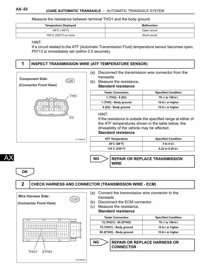
Measure the resistance between terminal THO1 and the body ground.
HINT:If a circuit related to the ATF (Automatic Transmission Fluid) temperature sensor becomes open, P0713 is immediately set (within 0.5 seconds).
(a) Disconnect the transmission wire connector from the transaxle.
(b) Measure the resistance.Standard resistance
HINT:If the resistance is outside the specified range at either of the ATF temperatures shown in the table below, the driveability of the vehicle may be affected.Standard resistance
NG
OK
(a) Connect the transmission wire connector to the transaxle.
(b) Disconnect the ECM connector.(c) Measure the resistance.
Standard resistance
NG
Temperature Displayed Malfunction
-40°C (-40°F) Open circuit
150°C (302°F) or more Short circuit
1 INSPECT TRANSMISSION WIRE (ATF TEMPERATURE SENSOR)
C28
(Connector Front View)
Component Side:
THO
E2
C117650E01
Tester Connection Specified Condition
1 (THO) - 6 (E2) 79 Ω to 156 kΩ
1 (THO) - Body ground 10 kΩ or higher
6 (E2) - Body ground 10 kΩ or higher
ATF Temperature Specified Condition
20°C (68°F) 3 to 4 kΩ
110°C (230°F) 0.22 to 0.28 kΩ
REPAIR OR REPLACE TRANSMISSION WIRE
2 CHECK HARNESS AND CONNECTOR (TRANSMISSION WIRE - ECM)
C20Wire Harness Side:
(Connector Front View)
THO1 ETHO
A107892E03
Tester Connection Specified Condition
72 (THO1) - 95 (ETHO) 79 Ω to 156 kΩ
72 (THO1) - Body ground 10 kΩ or higher
95 (ETHO) - Body ground 10 kΩ or higher
REPAIR OR REPLACE HARNESS OR CONNECTOR
U340E AUTOMATIC TRANSAXLE – AUTOMATIC TRANSAXLE SYSTEM AX–53
X
AOK
REPLACE ECM
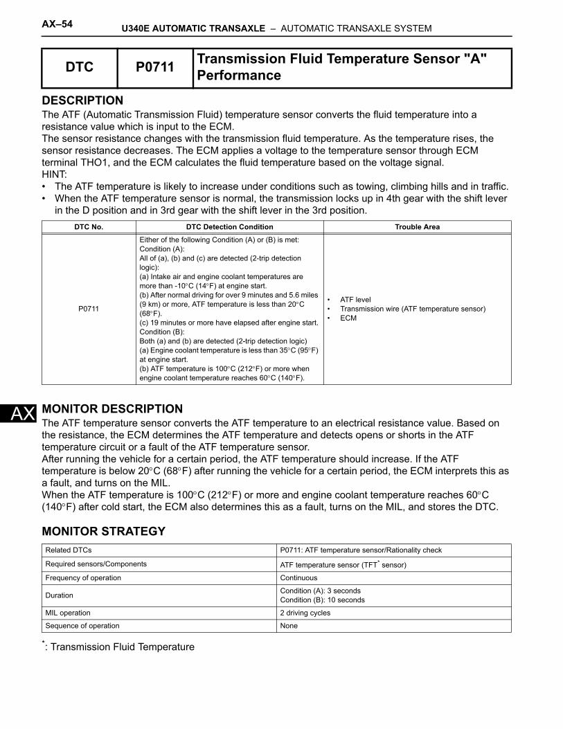
AX–54 U340E AUTOMATIC TRANSAXLE – AUTOMATIC TRANSAXLE SYSTEM
AX
DESCRIPTIONThe ATF (Automatic Transmission Fluid) temperature sensor converts the fluid temperature into a resistance value which is input to the ECM.The sensor resistance changes with the transmission fluid temperature. As the temperature rises, the sensor resistance decreases. The ECM applies a voltage to the temperature sensor through ECM terminal THO1, and the ECM calculates the fluid temperature based on the voltage signal.HINT:• The ATF temperature is likely to increase under conditions such as towing, climbing hills and in traffic.• When the ATF temperature sensor is normal, the transmission locks up in 4th gear with the shift lever
in the D position and in 3rd gear with the shift lever in the 3rd position.
MONITOR DESCRIPTIONThe ATF temperature sensor converts the ATF temperature to an electrical resistance value. Based on the resistance, the ECM determines the ATF temperature and detects opens or shorts in the ATF temperature circuit or a fault of the ATF temperature sensor.After running the vehicle for a certain period, the ATF temperature should increase. If the ATF temperature is below 20°C (68°F) after running the vehicle for a certain period, the ECM interprets this as a fault, and turns on the MIL.When the ATF temperature is 100°C (212°F) or more and engine coolant temperature reaches 60°C (140°F) after cold start, the ECM also determines this as a fault, turns on the MIL, and stores the DTC.
MONITOR STRATEGY
*: Transmission Fluid Temperature
DTC P0711 Transmission Fluid Temperature Sensor "A" Performance
DTC No. DTC Detection Condition Trouble Area
P0711
Either of the following Condition (A) or (B) is met:Condition (A):All of (a), (b) and (c) are detected (2-trip detection logic):(a) Intake air and engine coolant temperatures are more than -10°C (14°F) at engine start.(b) After normal driving for over 9 minutes and 5.6 miles (9 km) or more, ATF temperature is less than 20°C (68°F).(c) 19 minutes or more have elapsed after engine start.Condition (B):Both (a) and (b) are detected (2-trip detection logic)(a) Engine coolant temperature is less than 35°C (95°F) at engine start.(b) ATF temperature is 100°C (212°F) or more when engine coolant temperature reaches 60°C (140°F).
• ATF level• Transmission wire (ATF temperature sensor)• ECM
Related DTCs P0711: ATF temperature sensor/Rationality check
Required sensors/Components ATF temperature sensor (TFT* sensor)
Frequency of operation Continuous
Duration Condition (A): 3 secondsCondition (B): 10 seconds
MIL operation 2 driving cycles
Sequence of operation None
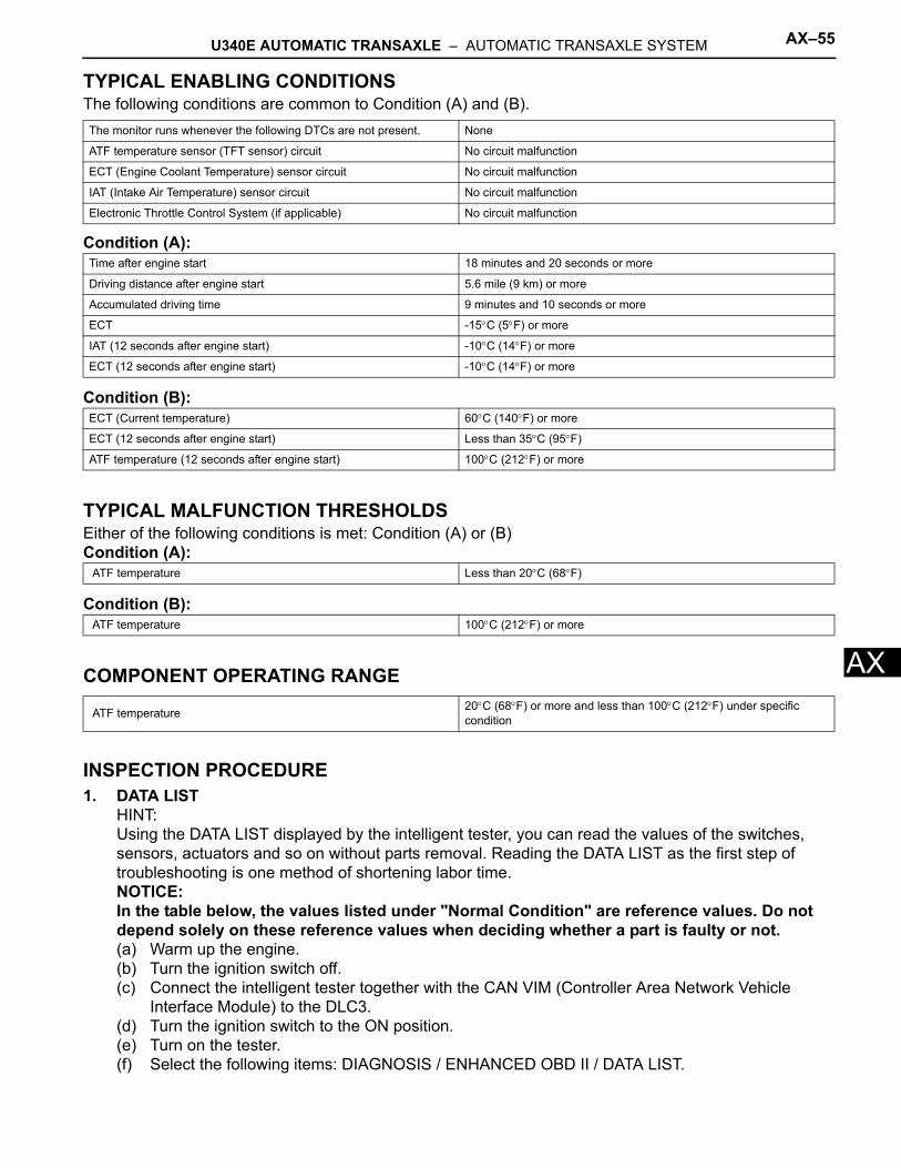
U340E AUTOMATIC TRANSAXLE – AUTOMATIC TRANSAXLE SYSTEM AX–55
X
ATYPICAL ENABLING CONDITIONSThe following conditions are common to Condition (A) and (B).
Condition (A):
Condition (B):
TYPICAL MALFUNCTION THRESHOLDSEither of the following conditions is met: Condition (A) or (B)Condition (A):
Condition (B):
COMPONENT OPERATING RANGE
INSPECTION PROCEDURE1. DATA LIST
HINT:Using the DATA LIST displayed by the intelligent tester, you can read the values of the switches, sensors, actuators and so on without parts removal. Reading the DATA LIST as the first step of troubleshooting is one method of shortening labor time.NOTICE:In the table below, the values listed under "Normal Condition" are reference values. Do not depend solely on these reference values when deciding whether a part is faulty or not.(a) Warm up the engine.(b) Turn the ignition switch off.(c) Connect the intelligent tester together with the CAN VIM (Controller Area Network Vehicle
Interface Module) to the DLC3.(d) Turn the ignition switch to the ON position.(e) Turn on the tester.(f) Select the following items: DIAGNOSIS / ENHANCED OBD II / DATA LIST.
The monitor runs whenever the following DTCs are not present. None
ATF temperature sensor (TFT sensor) circuit No circuit malfunction
ECT (Engine Coolant Temperature) sensor circuit No circuit malfunction
IAT (Intake Air Temperature) sensor circuit No circuit malfunction
Electronic Throttle Control System (if applicable) No circuit malfunction
Time after engine start 18 minutes and 20 seconds or more
Driving distance after engine start 5.6 mile (9 km) or more
Accumulated driving time 9 minutes and 10 seconds or more
ECT -15°C (5°F) or more
IAT (12 seconds after engine start) -10°C (14°F) or more
ECT (12 seconds after engine start) -10°C (14°F) or more
ECT (Current temperature) 60°C (140°F) or more
ECT (12 seconds after engine start) Less than 35°C (95°F)
ATF temperature (12 seconds after engine start) 100°C (212°F) or more
ATF temperature Less than 20°C (68°F)
ATF temperature 100°C (212°F) or more
ATF temperature 20°C (68°F) or more and less than 100°C (212°F) under specific condition
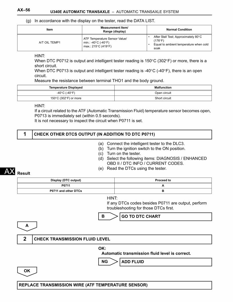
AX–56 U340E AUTOMATIC TRANSAXLE – AUTOMATIC TRANSAXLE SYSTEM
AX
(g) In accordance with the display on the tester, read the DATA LIST.
HINT:When DTC P0712 is output and intelligent tester reading is 150°C (302°F) or more, there is a short circuit.When DTC P0713 is output and intelligent tester reading is -40°C (-40°F), there is an open circuit.Measure the resistance between terminal THO1 and the body ground.
HINT:If a circuit related to the ATF (Automatic Transmission Fluid) temperature sensor becomes open, P0713 is immediately set (within 0.5 seconds).It is not necessary to inspect the circuit when P0711 is set.
(a) Connect the intelligent tester to the DLC3.(b) Turn the ignition switch to the ON position.(c) Turn on the tester.(d) Select the following items: DIAGNOSIS / ENHANCED
OBD II / DTC INFO / CURRENT CODES.(e) Read the DTCs using the tester.
Result
HINT:If any DTCs codes besides P0711 are output, perform troubleshooting for those DTCs first.
B
A
OK:Automatic transmission fluid level is correct.
NG
OK
Item Measurement Item/Range (display) Normal Condition
A/T OIL TEMP1ATF Temperature Sensor Value/min.: -40°C (-40°F)max.: 215°C (419°F)
• After Stall Test; Approximately 80°C (176°F)
• Equal to ambient temperature when cold soak
Temperature Displayed Malfunction
-40°C (-40°F) Open circuit
150°C (302°F) or more Short circuit
1 CHECK OTHER DTCS OUTPUT (IN ADDITION TO DTC P0711)
Display (DTC output) Proceed to
P0711 A
P0711 and other DTCs B
GO TO DTC CHART
2 CHECK TRANSMISSION FLUID LEVEL
ADD FLUID
REPLACE TRANSMISSION WIRE (ATF TEMPERATURE SENSOR)
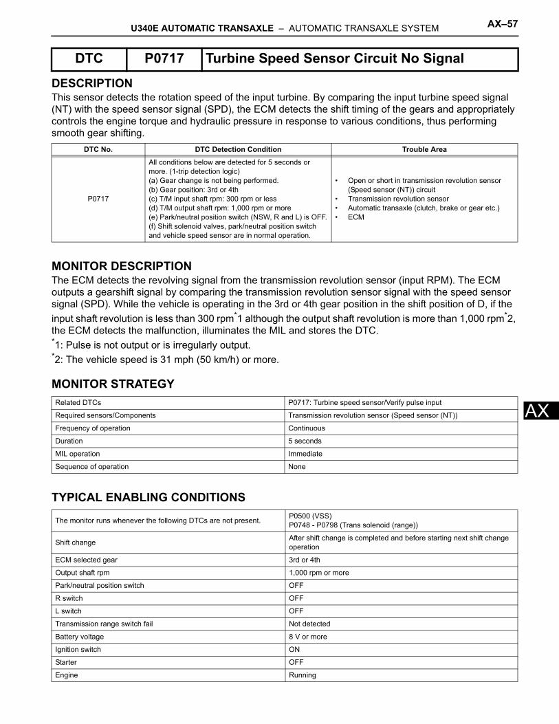
U340E AUTOMATIC TRANSAXLE – AUTOMATIC TRANSAXLE SYSTEM AX–57
X
ADESCRIPTIONThis sensor detects the rotation speed of the input turbine. By comparing the input turbine speed signal (NT) with the speed sensor signal (SPD), the ECM detects the shift timing of the gears and appropriately controls the engine torque and hydraulic pressure in response to various conditions, thus performing smooth gear shifting.
MONITOR DESCRIPTIONThe ECM detects the revolving signal from the transmission revolution sensor (input RPM). The ECM outputs a gearshift signal by comparing the transmission revolution sensor signal with the speed sensor signal (SPD). While the vehicle is operating in the 3rd or 4th gear position in the shift position of D, if the input shaft revolution is less than 300 rpm*1 although the output shaft revolution is more than 1,000 rpm*2, the ECM detects the malfunction, illuminates the MIL and stores the DTC.*1: Pulse is not output or is irregularly output.*2: The vehicle speed is 31 mph (50 km/h) or more.
MONITOR STRATEGY
TYPICAL ENABLING CONDITIONS
DTC P0717 Turbine Speed Sensor Circuit No Signal
DTC No. DTC Detection Condition Trouble Area
P0717
All conditions below are detected for 5 seconds or more. (1-trip detection logic)(a) Gear change is not being performed.(b) Gear position: 3rd or 4th(c) T/M input shaft rpm: 300 rpm or less(d) T/M output shaft rpm: 1,000 rpm or more(e) Park/neutral position switch (NSW, R and L) is OFF.(f) Shift solenoid valves, park/neutral position switch and vehicle speed sensor are in normal operation.
• Open or short in transmission revolution sensor (Speed sensor (NT)) circuit
• Transmission revolution sensor• Automatic transaxle (clutch, brake or gear etc.)• ECM
Related DTCs P0717: Turbine speed sensor/Verify pulse input
Required sensors/Components Transmission revolution sensor (Speed sensor (NT))
Frequency of operation Continuous
Duration 5 seconds
MIL operation Immediate
Sequence of operation None
The monitor runs whenever the following DTCs are not present. P0500 (VSS)P0748 - P0798 (Trans solenoid (range))
Shift change After shift change is completed and before starting next shift change operation
ECM selected gear 3rd or 4th
Output shaft rpm 1,000 rpm or more
Park/neutral position switch OFF
R switch OFF
L switch OFF
Transmission range switch fail Not detected
Battery voltage 8 V or more
Ignition switch ON
Starter OFF
Engine Running
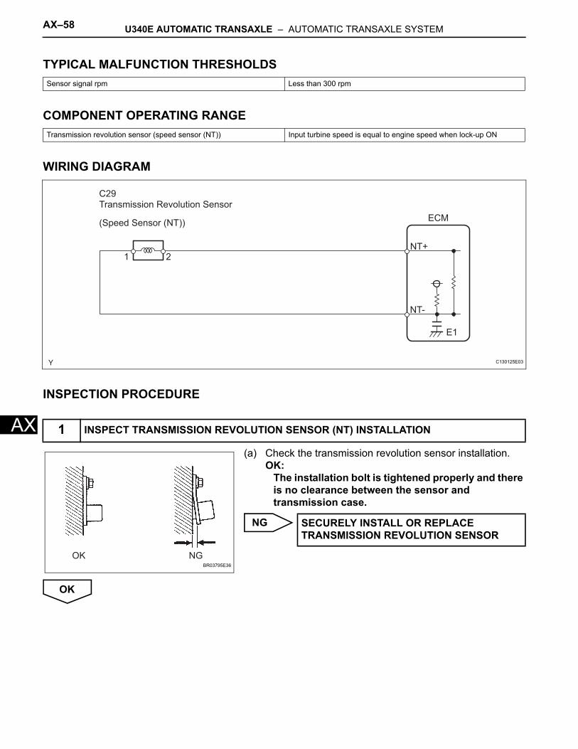
AX–58 U340E AUTOMATIC TRANSAXLE – AUTOMATIC TRANSAXLE SYSTEM
AX
TYPICAL MALFUNCTION THRESHOLDS
COMPONENT OPERATING RANGE
WIRING DIAGRAM
INSPECTION PROCEDURE
(a) Check the transmission revolution sensor installation.OK:
The installation bolt is tightened properly and there is no clearance between the sensor and transmission case.
NG
OK
Sensor signal rpm Less than 300 rpm
Transmission revolution sensor (speed sensor (NT)) Input turbine speed is equal to engine speed when lock-up ON
1 INSPECT TRANSMISSION REVOLUTION SENSOR (NT) INSTALLATION
21
ECM
NT+
NT-
E1
Transmission Revolution Sensor
(Speed Sensor (NT))
C29
C130125E03
OK NGBR03795E36
SECURELY INSTALL OR REPLACE TRANSMISSION REVOLUTION SENSOR
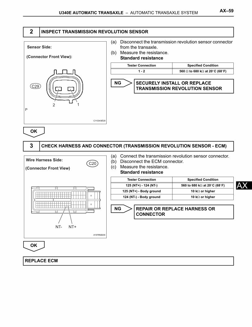
U340E AUTOMATIC TRANSAXLE – AUTOMATIC TRANSAXLE SYSTEM AX–59
X
A(a) Disconnect the transmission revolution sensor connector from the transaxle.
(b) Measure the resistance.Standard resistance
NG
OK
(a) Connect the transmission revolution sensor connector.(b) Disconnect the ECM connector.(c) Measure the resistance.
Standard resistance
NG
OK
2 INSPECT TRANSMISSION REVOLUTION SENSOR
12
Sensor Side:
(Connector Front View):
C29
C110343E29
Tester Connection Specified Condition
1 - 2 560 Ω to 680 kΩ at 20°C (68°F)
SECURELY INSTALL OR REPLACE TRANSMISSION REVOLUTION SENSOR
3 CHECK HARNESS AND CONNECTOR (TRANSMISSION REVOLUTION SENSOR - ECM)
C20Wire Harness Side:
(Connector Front View)
NT- NT+
A107892E04
Tester Connection Specified Condition
125 (NT+) - 124 (NT-) 560 to 680 kΩ at 20°C (68°F)
125 (NT+) - Body ground 10 kΩ or higher
124 (NT-) - Body ground 10 kΩ or higher
REPAIR OR REPLACE HARNESS OR CONNECTOR
REPLACE ECM
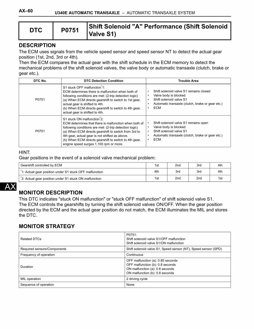
AX–60 U340E AUTOMATIC TRANSAXLE – AUTOMATIC TRANSAXLE SYSTEM
AX
DESCRIPTIONThe ECM uses signals from the vehicle speed sensor and speed sensor NT to detect the actual gear position (1st, 2nd, 3rd or 4th).Then the ECM compares the actual gear with the shift schedule in the ECM memory to detect the mechanical problems of the shift solenoid valves, the valve body or automatic transaxle (clutch, brake or gear etc.).
HINT:Gear positions in the event of a solenoid valve mechanical problem:
MONITOR DESCRIPTIONThis DTC indicates "stuck ON malfunction" or "stuck OFF malfunction" of shift solenoid valve S1.The ECM controls the gearshifts by turning the shift solenoid valves ON/OFF. When the gear position directed by the ECM and the actual gear position do not match, the ECM illuminates the MIL and stores the DTC.
MONITOR STRATEGY
DTC P0751 Shift Solenoid "A" Performance (Shift Solenoid Valve S1)
DTC No. DTC Detection Condition Trouble Area
P0751
S1 stuck OFF malfunction*1:ECM determines there is malfunction when both of following conditions are met: (2-trip detection logic)(a) When ECM directs gearshift to switch to 1st gear, actual gear is shifted to 4th.(b) When ECM directs gearshift to switch to 4th gear, actual gear is shifted to 4th.
• Shift solenoid valve S1 remains closed• Valve body is blocked• Shift solenoid valve S1• Automatic transaxle (clutch, brake or gear etc.)• ECM
P0751
S1 stuck ON malfunction*2:ECM determines that there is malfunction when both of following conditions are met: (2-trip detection logic)(a) When ECM directs gearshift to switch from 3rd to 4th gear, actual gear is not shifted as above.(b) When ECM directs gearshift to switch to 4th gear, engine speed surges 1,100 rpm or more.
• Shift solenoid valve S1 remains open• Valve body is blocked• Shift solenoid valve S1• Automatic transaxle (clutch, brake or gear etc.)• ECM
Gearshift controlled by ECM 1st 2nd 3rd 4th*1: Actual gear position under S1 stuck OFF malfunction 4th 3rd 3rd 4th
*2: Actual gear position under S1 stuck ON malfunction 1st 2nd 2nd 1st
Related DTCsP0751:Shift solenoid valve S1/OFF malfunctionShift solenoid valve S1/ON malfunction
Required sensors/Components Shift solenoid valve S1, Speed sensor (NT), Speed sensor (SPD)
Frequency of operation Continuous
Duration
OFF malfunction (a): 0.85 secondsOFF malfunction (b): 0.8 secondsON malfunction (a): 0.8 secondsON malfunction (b): 0.8 seconds
MIL operation 2 driving cycle
Sequence of operation None
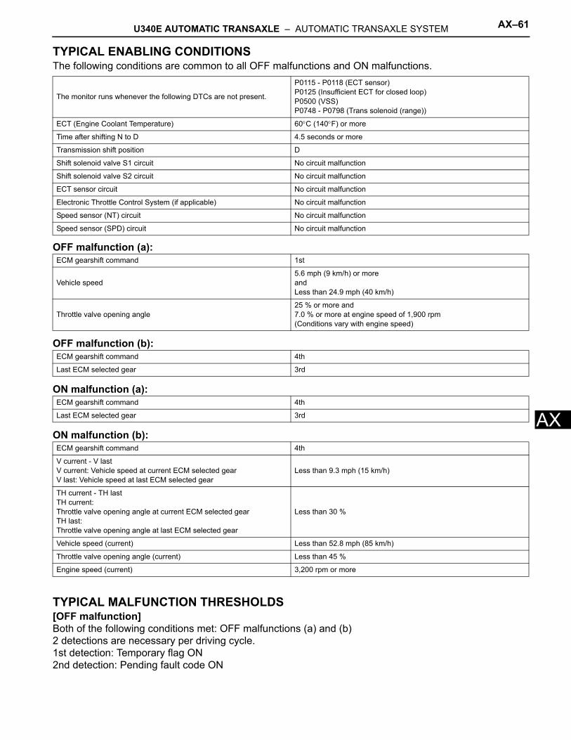
U340E AUTOMATIC TRANSAXLE – AUTOMATIC TRANSAXLE SYSTEM AX–61
X
ATYPICAL ENABLING CONDITIONSThe following conditions are common to all OFF malfunctions and ON malfunctions.
OFF malfunction (a):
OFF malfunction (b):
ON malfunction (a):
ON malfunction (b):
TYPICAL MALFUNCTION THRESHOLDS[OFF malfunction]Both of the following conditions met: OFF malfunctions (a) and (b)2 detections are necessary per driving cycle.1st detection: Temporary flag ON2nd detection: Pending fault code ON
The monitor runs whenever the following DTCs are not present.
P0115 - P0118 (ECT sensor)P0125 (Insufficient ECT for closed loop)P0500 (VSS)P0748 - P0798 (Trans solenoid (range))
ECT (Engine Coolant Temperature) 60°C (140°F) or more
Time after shifting N to D 4.5 seconds or more
Transmission shift position D
Shift solenoid valve S1 circuit No circuit malfunction
Shift solenoid valve S2 circuit No circuit malfunction
ECT sensor circuit No circuit malfunction
Electronic Throttle Control System (if applicable) No circuit malfunction
Speed sensor (NT) circuit No circuit malfunction
Speed sensor (SPD) circuit No circuit malfunction
ECM gearshift command 1st
Vehicle speed5.6 mph (9 km/h) or moreandLess than 24.9 mph (40 km/h)
Throttle valve opening angle25 % or more and7.0 % or more at engine speed of 1,900 rpm(Conditions vary with engine speed)
ECM gearshift command 4th
Last ECM selected gear 3rd
ECM gearshift command 4th
Last ECM selected gear 3rd
ECM gearshift command 4th
V current - V lastV current: Vehicle speed at current ECM selected gearV last: Vehicle speed at last ECM selected gear
Less than 9.3 mph (15 km/h)
TH current - TH lastTH current:Throttle valve opening angle at current ECM selected gearTH last:Throttle valve opening angle at last ECM selected gear
Less than 30 %
Vehicle speed (current) Less than 52.8 mph (85 km/h)
Throttle valve opening angle (current) Less than 45 %
Engine speed (current) 3,200 rpm or more
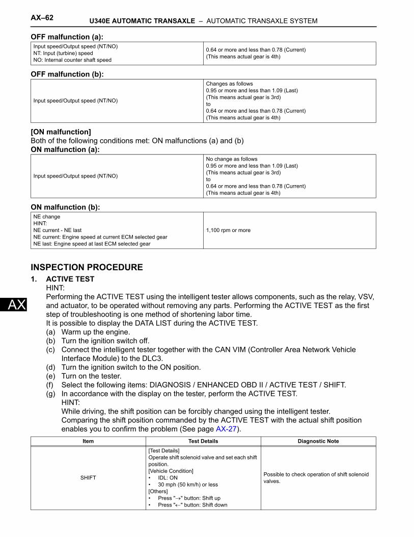
AX–62 U340E AUTOMATIC TRANSAXLE – AUTOMATIC TRANSAXLE SYSTEM
AX
OFF malfunction (a):
OFF malfunction (b):
[ON malfunction]Both of the following conditions met: ON malfunctions (a) and (b)ON malfunction (a):
ON malfunction (b):
INSPECTION PROCEDURE1. ACTIVE TEST
HINT:Performing the ACTIVE TEST using the intelligent tester allows components, such as the relay, VSV, and actuator, to be operated without removing any parts. Performing the ACTIVE TEST as the first step of troubleshooting is one method of shortening labor time.It is possible to display the DATA LIST during the ACTIVE TEST.(a) Warm up the engine.(b) Turn the ignition switch off.(c) Connect the intelligent tester together with the CAN VIM (Controller Area Network Vehicle
Interface Module) to the DLC3.(d) Turn the ignition switch to the ON position.(e) Turn on the tester.(f) Select the following items: DIAGNOSIS / ENHANCED OBD II / ACTIVE TEST / SHIFT.(g) In accordance with the display on the tester, perform the ACTIVE TEST.
HINT:While driving, the shift position can be forcibly changed using the intelligent tester.Comparing the shift position commanded by the ACTIVE TEST with the actual shift position enables you to confirm the problem (See page AX-27).
Input speed/Output speed (NT/NO)NT: Input (turbine) speedNO: Internal counter shaft speed
0.64 or more and less than 0.78 (Current)(This means actual gear is 4th)
Input speed/Output speed (NT/NO)
Changes as follows0.95 or more and less than 1.09 (Last)(This means actual gear is 3rd)to0.64 or more and less than 0.78 (Current)(This means actual gear is 4th)
Input speed/Output speed (NT/NO)
No change as follows0.95 or more and less than 1.09 (Last)(This means actual gear is 3rd)to0.64 or more and less than 0.78 (Current)(This means actual gear is 4th)
NE changeHINT:NE current - NE lastNE current: Engine speed at current ECM selected gearNE last: Engine speed at last ECM selected gear
1,100 rpm or more
Item Test Details Diagnostic Note
SHIFT
[Test Details]Operate shift solenoid valve and set each shift position.[Vehicle Condition]• IDL: ON• 30 mph (50 km/h) or less[Others]• Press "→" button: Shift up• Press "←" button: Shift down
Possible to check operation of shift solenoid valves.
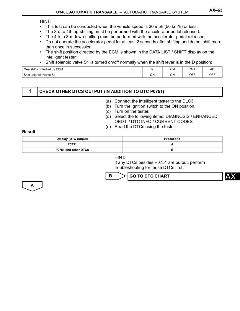
U340E AUTOMATIC TRANSAXLE – AUTOMATIC TRANSAXLE SYSTEM AX–63
X
AHINT:• This test can be conducted when the vehicle speed is 30 mph (50 km/h) or less.• The 3rd to 4th up-shifting must be performed with the accelerator pedal released.• The 4th to 3rd down-shifting must be performed with the accelerator pedal released.• Do not operate the accelerator pedal for at least 2 seconds after shifting and do not shift more
than once in succession.• The shift position directed by the ECM is shown in the DATA LIST / SHIFT display on the
intelligent tester.• Shift solenoid valve S1 is turned on/off normally when the shift lever is in the D position:
(a) Connect the intelligent tester to the DLC3.(b) Turn the ignition switch to the ON position.(c) Turn on the tester.(d) Select the following items: DIAGNOSIS / ENHANCED
OBD II / DTC INFO / CURRENT CODES.(e) Read the DTCs using the tester.
Result
HINT:If any DTCs besides P0751 are output, perform troubleshooting for those DTCs first.
B
A
Gearshift controlled by ECM 1st 2nd 3rd 4th
Shift solenoid valve S1 ON ON OFF OFF
1 CHECK OTHER DTCS OUTPUT (IN ADDITION TO DTC P0751)
Display (DTC output) Proceed to
P0751 A
P0751 and other DTCs B
GO TO DTC CHART
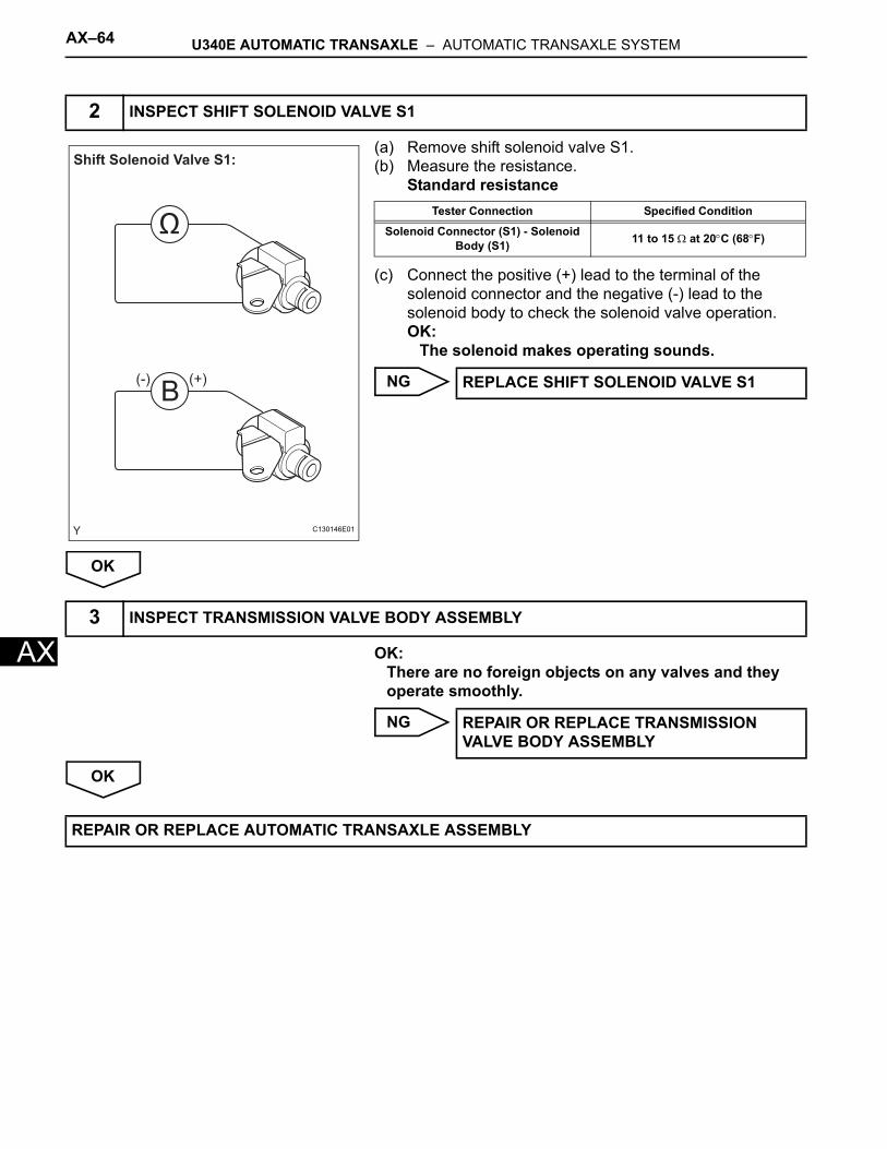
AX–64 U340E AUTOMATIC TRANSAXLE – AUTOMATIC TRANSAXLE SYSTEM
AX
(a) Remove shift solenoid valve S1.(b) Measure the resistance.
Standard resistance
(c) Connect the positive (+) lead to the terminal of the solenoid connector and the negative (-) lead to the solenoid body to check the solenoid valve operation.OK:
The solenoid makes operating sounds.
NG
OK
OK:There are no foreign objects on any valves and they operate smoothly.
NG
OK
2 INSPECT SHIFT SOLENOID VALVE S1
B
Ω
Shift Solenoid Valve S1:
(-) (+)
C130146E01
Tester Connection Specified Condition
Solenoid Connector (S1) - Solenoid Body (S1) 11 to 15 Ω at 20°C (68°F)
REPLACE SHIFT SOLENOID VALVE S1
3 INSPECT TRANSMISSION VALVE BODY ASSEMBLY
REPAIR OR REPLACE TRANSMISSION VALVE BODY ASSEMBLY
REPAIR OR REPLACE AUTOMATIC TRANSAXLE ASSEMBLY
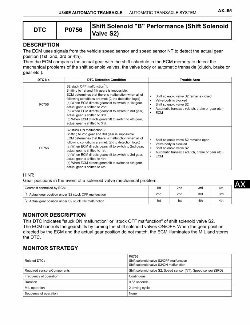
U340E AUTOMATIC TRANSAXLE – AUTOMATIC TRANSAXLE SYSTEM AX–65
X
ADESCRIPTIONThe ECM uses signals from the vehicle speed sensor and speed sensor NT to detect the actual gear position (1st, 2nd, 3rd or 4th).Then the ECM compares the actual gear with the shift schedule in the ECM memory to detect the mechanical problems of the shift solenoid valves, the valve body or automatic transaxle (clutch, brake or gear etc.).
HINT:Gear positions in the event of a solenoid valve mechanical problem:
MONITOR DESCRIPTIONThis DTC indicates "stuck ON malfunction" or "stuck OFF malfunction" of shift solenoid valve S2.The ECM controls the gearshifts by turning the shift solenoid valves ON/OFF. When the gear position directed by the ECM and the actual gear position do not match, the ECM illuminates the MIL and stores the DTC.
MONITOR STRATEGY
DTC P0756 Shift Solenoid "B" Performance (Shift Solenoid Valve S2)
DTC No. DTC Detection Condition Trouble Area
P0756
S2 stuck OFF malfunction*1:Shifting to 1st and 4th gears is impossible.ECM determines that there is malfunction when all of following conditions are met: (2-trip detection logic)(a) When ECM directs gearshift to switch to 1st gear, actual gear is shifted to 2nd.(b) When ECM directs gearshift to switch to 3rd gear, actual gear is shifted to 3rd.(c) When ECM directs gearshift to switch to 4th gear, actual gear is shifted to 3rd.
• Shift solenoid valve S2 remains closed• Valve body is blocked• Shift solenoid valve S2• Automatic transaxle (clutch, brake or gear etc.)• ECM
P0756
S2 stuck ON malfunction*2:Shifting to 2nd gear and 3rd gear is impossible.ECM determines that there is malfunction when all of following conditions are met: (2-trip detection logic)(a) When ECM directs gearshift to switch to 2nd gear, actual gear is shifted to 1st.(b) When ECM directs gearshift to switch to 3rd gear, actual gear is shifted to 4th.(c) When ECM directs gearshift to switch to 4th gear, actual gear is shifted to 4th.
• Shift solenoid valve S2 remains open• Valve body is blocked• Shift solenoid valve S2• Automatic transaxle (clutch, brake or gear etc.)• ECM
Gearshift controlled by ECM 1st 2nd 3rd 4th*1: Actual gear position under S2 stuck OFF malfunction 2nd 2nd 3rd 3rd
*2: Actual gear position under S2 stuck ON malfunction 1st 1st 4th 4th
Related DTCsP0756:Shift solenoid valve S2/OFF malfunctionShift solenoid valve S2/ON malfunction
Required sensors/Components Shift solenoid valve S2, Speed sensor (NT), Speed sensor (SPD)
Frequency of operation Continuous
Duration 0.85 seconds
MIL operation 2 driving cycle
Sequence of operation None
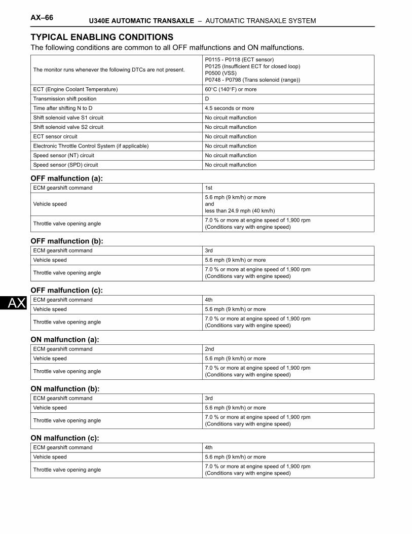
AX–66 U340E AUTOMATIC TRANSAXLE – AUTOMATIC TRANSAXLE SYSTEM
AX
TYPICAL ENABLING CONDITIONSThe following conditions are common to all OFF malfunctions and ON malfunctions.
OFF malfunction (a):
OFF malfunction (b):
OFF malfunction (c):
ON malfunction (a):
ON malfunction (b):
ON malfunction (c):
The monitor runs whenever the following DTCs are not present.
P0115 - P0118 (ECT sensor)P0125 (Insufficient ECT for closed loop)P0500 (VSS)P0748 - P0798 (Trans solenoid (range))
ECT (Engine Coolant Temperature) 60°C (140°F) or more
Transmission shift position D
Time after shifting N to D 4.5 seconds or more
Shift solenoid valve S1 circuit No circuit malfunction
Shift solenoid valve S2 circuit No circuit malfunction
ECT sensor circuit No circuit malfunction
Electronic Throttle Control System (if applicable) No circuit malfunction
Speed sensor (NT) circuit No circuit malfunction
Speed sensor (SPD) circuit No circuit malfunction
ECM gearshift command 1st
Vehicle speed5.6 mph (9 km/h) or moreandless than 24.9 mph (40 km/h)
Throttle valve opening angle 7.0 % or more at engine speed of 1,900 rpm(Conditions vary with engine speed)
ECM gearshift command 3rd
Vehicle speed 5.6 mph (9 km/h) or more
Throttle valve opening angle 7.0 % or more at engine speed of 1,900 rpm(Conditions vary with engine speed)
ECM gearshift command 4th
Vehicle speed 5.6 mph (9 km/h) or more
Throttle valve opening angle 7.0 % or more at engine speed of 1,900 rpm(Conditions vary with engine speed)
ECM gearshift command 2nd
Vehicle speed 5.6 mph (9 km/h) or more
Throttle valve opening angle 7.0 % or more at engine speed of 1,900 rpm(Conditions vary with engine speed)
ECM gearshift command 3rd
Vehicle speed 5.6 mph (9 km/h) or more
Throttle valve opening angle 7.0 % or more at engine speed of 1,900 rpm(Conditions vary with engine speed)
ECM gearshift command 4th
Vehicle speed 5.6 mph (9 km/h) or more
Throttle valve opening angle 7.0 % or more at engine speed of 1,900 rpm(Conditions vary with engine speed)
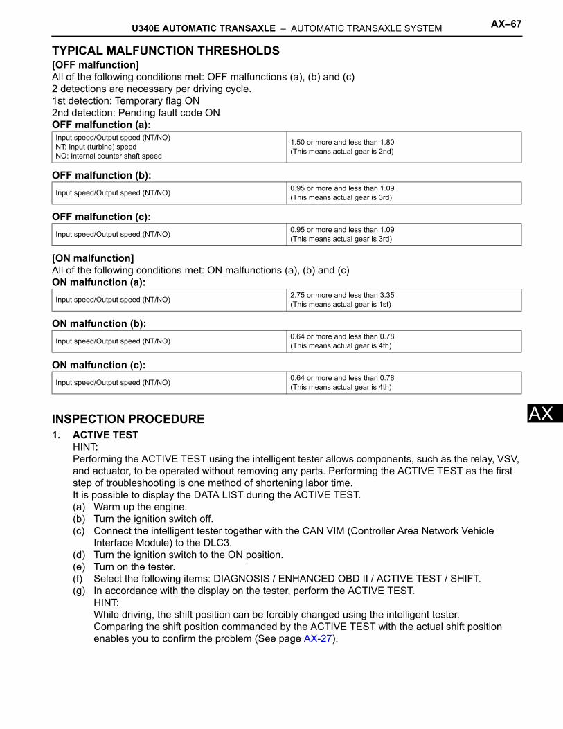
U340E AUTOMATIC TRANSAXLE – AUTOMATIC TRANSAXLE SYSTEM AX–67
X
ATYPICAL MALFUNCTION THRESHOLDS[OFF malfunction]All of the following conditions met: OFF malfunctions (a), (b) and (c)2 detections are necessary per driving cycle.1st detection: Temporary flag ON2nd detection: Pending fault code ONOFF malfunction (a):
OFF malfunction (b):
OFF malfunction (c):
[ON malfunction]All of the following conditions met: ON malfunctions (a), (b) and (c)ON malfunction (a):
ON malfunction (b):
ON malfunction (c):
INSPECTION PROCEDURE1. ACTIVE TEST
HINT:Performing the ACTIVE TEST using the intelligent tester allows components, such as the relay, VSV, and actuator, to be operated without removing any parts. Performing the ACTIVE TEST as the first step of troubleshooting is one method of shortening labor time.It is possible to display the DATA LIST during the ACTIVE TEST.(a) Warm up the engine.(b) Turn the ignition switch off.(c) Connect the intelligent tester together with the CAN VIM (Controller Area Network Vehicle
Interface Module) to the DLC3.(d) Turn the ignition switch to the ON position.(e) Turn on the tester.(f) Select the following items: DIAGNOSIS / ENHANCED OBD II / ACTIVE TEST / SHIFT.(g) In accordance with the display on the tester, perform the ACTIVE TEST.
HINT:While driving, the shift position can be forcibly changed using the intelligent tester.Comparing the shift position commanded by the ACTIVE TEST with the actual shift position enables you to confirm the problem (See page AX-27).
Input speed/Output speed (NT/NO)NT: Input (turbine) speedNO: Internal counter shaft speed
1.50 or more and less than 1.80(This means actual gear is 2nd)
Input speed/Output speed (NT/NO) 0.95 or more and less than 1.09(This means actual gear is 3rd)
Input speed/Output speed (NT/NO) 0.95 or more and less than 1.09(This means actual gear is 3rd)
Input speed/Output speed (NT/NO) 2.75 or more and less than 3.35(This means actual gear is 1st)
Input speed/Output speed (NT/NO) 0.64 or more and less than 0.78(This means actual gear is 4th)
Input speed/Output speed (NT/NO) 0.64 or more and less than 0.78(This means actual gear is 4th)
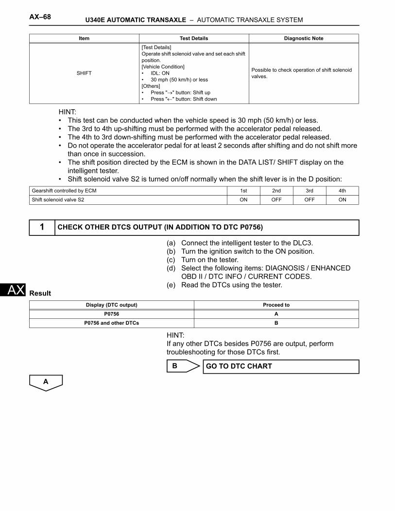
AX–68 U340E AUTOMATIC TRANSAXLE – AUTOMATIC TRANSAXLE SYSTEM
AX
HINT:• This test can be conducted when the vehicle speed is 30 mph (50 km/h) or less.• The 3rd to 4th up-shifting must be performed with the accelerator pedal released.• The 4th to 3rd down-shifting must be performed with the accelerator pedal released.• Do not operate the accelerator pedal for at least 2 seconds after shifting and do not shift more
than once in succession.• The shift position directed by the ECM is shown in the DATA LIST/ SHIFT display on the
intelligent tester.• Shift solenoid valve S2 is turned on/off normally when the shift lever is in the D position:
(a) Connect the intelligent tester to the DLC3.(b) Turn the ignition switch to the ON position.(c) Turn on the tester.(d) Select the following items: DIAGNOSIS / ENHANCED
OBD II / DTC INFO / CURRENT CODES.(e) Read the DTCs using the tester.
Result
HINT:If any other DTCs besides P0756 are output, perform troubleshooting for those DTCs first.
B
A
Item Test Details Diagnostic Note
SHIFT
[Test Details]Operate shift solenoid valve and set each shift position.[Vehicle Condition]• IDL: ON• 30 mph (50 km/h) or less[Others]• Press "→" button: Shift up• Press "←" button: Shift down
Possible to check operation of shift solenoid valves.
Gearshift controlled by ECM 1st 2nd 3rd 4th
Shift solenoid valve S2 ON OFF OFF ON
1 CHECK OTHER DTCS OUTPUT (IN ADDITION TO DTC P0756)
Display (DTC output) Proceed to
P0756 A
P0756 and other DTCs B
GO TO DTC CHART
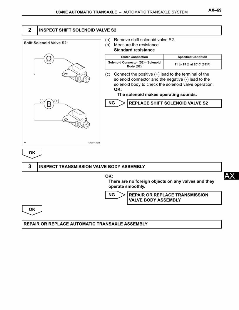
U340E AUTOMATIC TRANSAXLE – AUTOMATIC TRANSAXLE SYSTEM AX–69
X
A(a) Remove shift solenoid valve S2.(b) Measure the resistance.
Standard resistance
(c) Connect the positive (+) lead to the terminal of the solenoid connector and the negative (-) lead to the solenoid body to check the solenoid valve operation.OK:
The solenoid makes operating sounds.
NG
OK
OK:There are no foreign objects on any valves and they operate smoothly.
NG
OK
2 INSPECT SHIFT SOLENOID VALVE S2
B
Ω
Shift Solenoid Valve S2:
(-) (+)
C130147E01
Tester Connection Specified Condition
Solenoid Connector (S2) - Solenoid Body (S2) 11 to 15 Ω at 20°C (68°F)
REPLACE SHIFT SOLENOID VALVE S2
3 INSPECT TRANSMISSION VALVE BODY ASSEMBLY
REPAIR OR REPLACE TRANSMISSION VALVE BODY ASSEMBLY
REPAIR OR REPLACE AUTOMATIC TRANSAXLE ASSEMBLY
AX–70 U340E AUTOMATIC TRANSAXLE – AUTOMATIC TRANSAXLE SYSTEM
AX
DESCRIPTIONShift solenoid valve ST is switched OFF-ON-OFF in accordance with signals from the ECM when up-shifting and down-shifting between the 3rd and the 4th gears. This reduces the shock of gear shifting between these positions.
MONITOR DESCRIPTIONWhen there is an open or short circuit in the shift solenoid valve circuit, the ECM detects the problem and the MIL comes on.
MONITOR STRATEGY
TYPICAL ENABLING CONDITIONSP0787: Range check (Low resistance)
P0788: Range check (High resistance)
DTC P0787 Shift / Timing Solenoid Low (Shift Solenoid Valve ST)
DTC P0788 Shift / Timing Solenoid High (Shift Solenoid Valve ST)
DTC No. DTC Detection Condition Trouble Area
P0787ECM detects short in solenoid valve ST circuit 4 times when solenoid valve ST is operated. (1-trip detection logic)
• Short in shift solenoid valve ST circuit• Shift solenoid valve ST• ECM
P0788ECM detects open in solenoid valve ST circuit 4 times when solenoid valve ST is not operated. (1-trip detection logic)
• Open in shift solenoid valve ST circuit• Shift solenoid valve ST• ECM
Related DTCs P0787: Shift timing solenoid/Range check (Low resistance)P0788: Shift timing solenoid/Range check (High resistance)
Required sensors/Components Shift solenoid valve ST
Frequency of operation Continuous
Duration 0.128 seconds
MIL operation Immediate
Sequence of operation None
The monitor runs whenever the following DTCs are not present None
Solenoid ON
Time after solenoid OFF to ON More than 0.008 seconds
Battery voltage 8 V or more
Ignition switch ON
Starter OFF
The monitor runs whenever the following DTCs are not present None
Solenoid OFF
Time after solenoid ON to OFF More than 0.008 seconds
Battery voltage 8 V or more
Ignition switch ON
Starter OFF
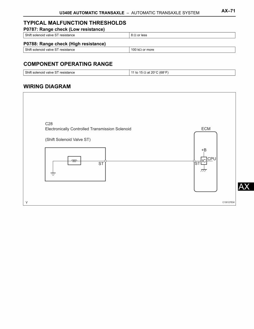
U340E AUTOMATIC TRANSAXLE – AUTOMATIC TRANSAXLE SYSTEM AX–71
X
ATYPICAL MALFUNCTION THRESHOLDSP0787: Range check (Low resistance)
P0788: Range check (High resistance)
COMPONENT OPERATING RANGE
WIRING DIAGRAM
Shift solenoid valve ST resistance 8 Ω or less
Shift solenoid valve ST resistance 100 kΩ or more
Shift solenoid valve ST resistance 11 to 15 Ω at 20°C (68°F)
C28
Electronically Controlled Transmission Solenoid
(Shift Solenoid Valve ST)
STIC
STCPU
ECM
+B
C130127E04
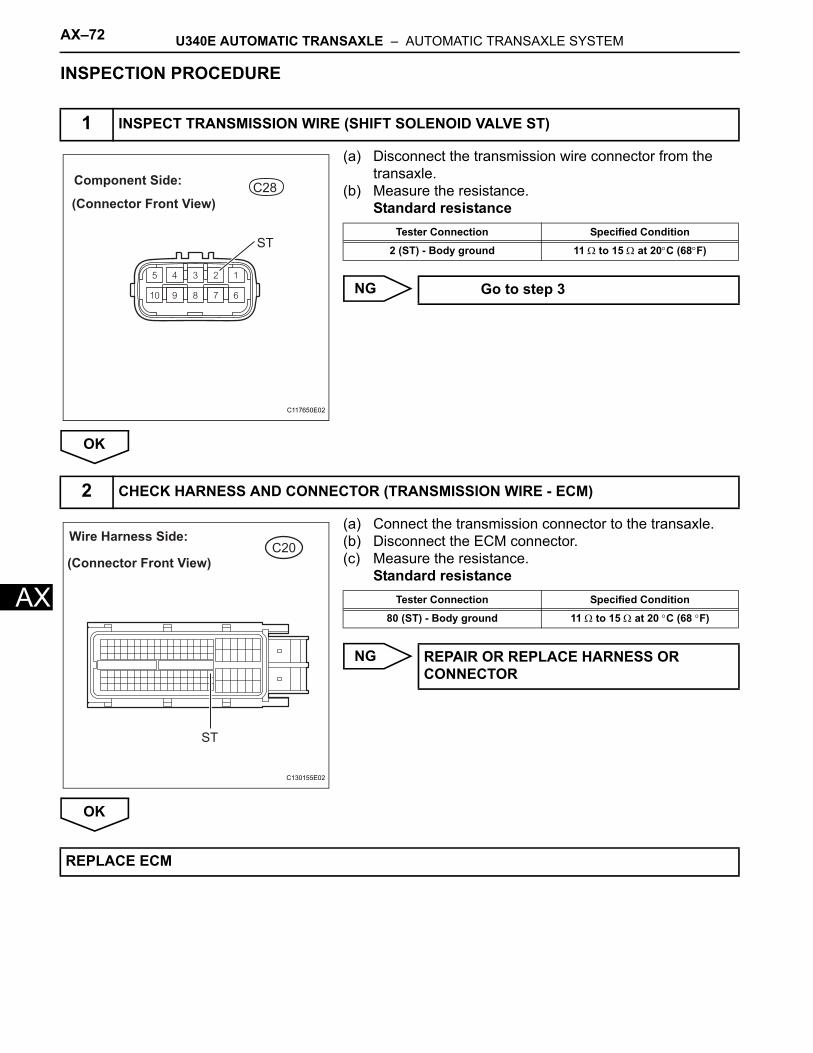
AX–72 U340E AUTOMATIC TRANSAXLE – AUTOMATIC TRANSAXLE SYSTEM
AX
INSPECTION PROCEDURE
(a) Disconnect the transmission wire connector from the transaxle.
(b) Measure the resistance.Standard resistance
NG
OK
(a) Connect the transmission connector to the transaxle.(b) Disconnect the ECM connector.(c) Measure the resistance.
Standard resistance
NG
OK
1 INSPECT TRANSMISSION WIRE (SHIFT SOLENOID VALVE ST)
C28
(Connector Front View)
Component Side:
ST
C117650E02
Tester Connection Specified Condition
2 (ST) - Body ground 11 Ω to 15 Ω at 20°C (68°F)
Go to step 3
2 CHECK HARNESS AND CONNECTOR (TRANSMISSION WIRE - ECM)
C20Wire Harness Side:
(Connector Front View)
ST
C130155E02
Tester Connection Specified Condition
80 (ST) - Body ground 11 Ω to 15 Ω at 20 °C (68 °F)
REPAIR OR REPLACE HARNESS OR CONNECTOR
REPLACE ECM
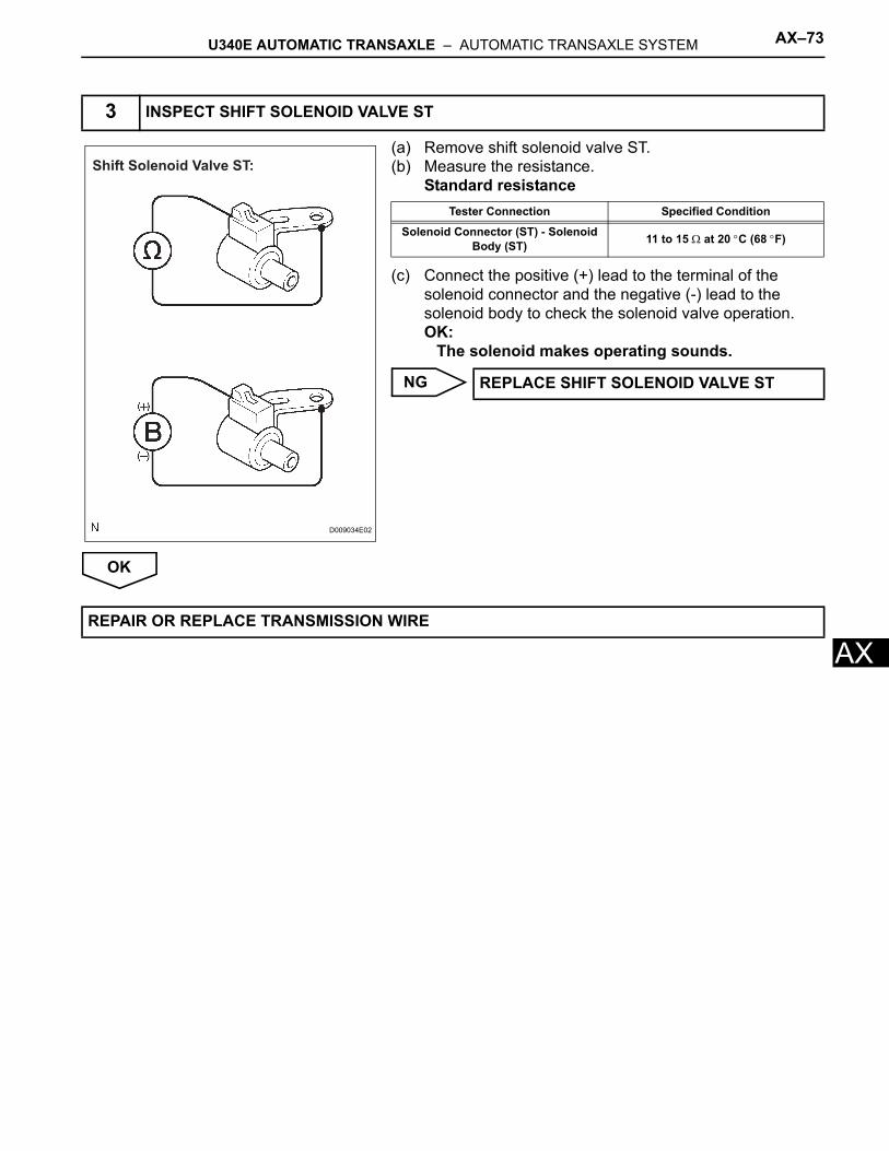
U340E AUTOMATIC TRANSAXLE – AUTOMATIC TRANSAXLE SYSTEM AX–73
X
A(a) Remove shift solenoid valve ST.(b) Measure the resistance.
Standard resistance
(c) Connect the positive (+) lead to the terminal of the solenoid connector and the negative (-) lead to the solenoid body to check the solenoid valve operation.OK:
The solenoid makes operating sounds.
NG
OK
3 INSPECT SHIFT SOLENOID VALVE ST
Shift Solenoid Valve ST:
D009034E02
Tester Connection Specified Condition
Solenoid Connector (ST) - Solenoid Body (ST) 11 to 15 Ω at 20 °C (68 °F)
REPLACE SHIFT SOLENOID VALVE ST
REPAIR OR REPLACE TRANSMISSION WIRE
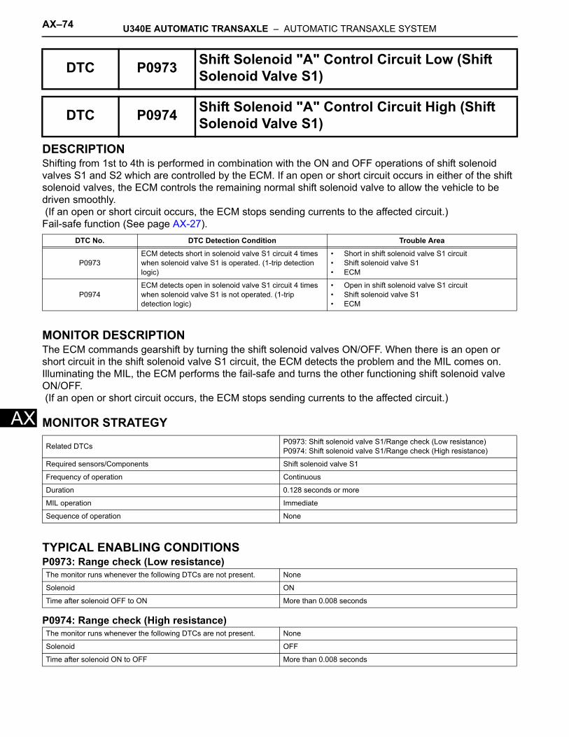
AX–74 U340E AUTOMATIC TRANSAXLE – AUTOMATIC TRANSAXLE SYSTEM
AX
DESCRIPTIONShifting from 1st to 4th is performed in combination with the ON and OFF operations of shift solenoid valves S1 and S2 which are controlled by the ECM. If an open or short circuit occurs in either of the shift solenoid valves, the ECM controls the remaining normal shift solenoid valve to allow the vehicle to be driven smoothly. (If an open or short circuit occurs, the ECM stops sending currents to the affected circuit.) Fail-safe function (See page AX-27).
MONITOR DESCRIPTIONThe ECM commands gearshift by turning the shift solenoid valves ON/OFF. When there is an open or short circuit in the shift solenoid valve S1 circuit, the ECM detects the problem and the MIL comes on. Illuminating the MIL, the ECM performs the fail-safe and turns the other functioning shift solenoid valve ON/OFF. (If an open or short circuit occurs, the ECM stops sending currents to the affected circuit.)
MONITOR STRATEGY
TYPICAL ENABLING CONDITIONSP0973: Range check (Low resistance)
P0974: Range check (High resistance)
DTC P0973 Shift Solenoid "A" Control Circuit Low (Shift Solenoid Valve S1)
DTC P0974 Shift Solenoid "A" Control Circuit High (Shift Solenoid Valve S1)
DTC No. DTC Detection Condition Trouble Area
P0973ECM detects short in solenoid valve S1 circuit 4 times when solenoid valve S1 is operated. (1-trip detection logic)
• Short in shift solenoid valve S1 circuit• Shift solenoid valve S1• ECM
P0974ECM detects open in solenoid valve S1 circuit 4 times when solenoid valve S1 is not operated. (1-trip detection logic)
• Open in shift solenoid valve S1 circuit• Shift solenoid valve S1• ECM
Related DTCs P0973: Shift solenoid valve S1/Range check (Low resistance)P0974: Shift solenoid valve S1/Range check (High resistance)
Required sensors/Components Shift solenoid valve S1
Frequency of operation Continuous
Duration 0.128 seconds or more
MIL operation Immediate
Sequence of operation None
The monitor runs whenever the following DTCs are not present. None
Solenoid ON
Time after solenoid OFF to ON More than 0.008 seconds
The monitor runs whenever the following DTCs are not present. None
Solenoid OFF
Time after solenoid ON to OFF More than 0.008 seconds
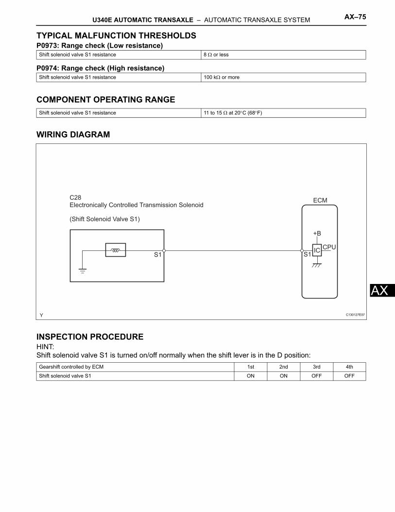
U340E AUTOMATIC TRANSAXLE – AUTOMATIC TRANSAXLE SYSTEM AX–75
X
ATYPICAL MALFUNCTION THRESHOLDSP0973: Range check (Low resistance)
P0974: Range check (High resistance)
COMPONENT OPERATING RANGE
WIRING DIAGRAM
INSPECTION PROCEDUREHINT:Shift solenoid valve S1 is turned on/off normally when the shift lever is in the D position:
Shift solenoid valve S1 resistance 8 Ω or less
Shift solenoid valve S1 resistance 100 kΩ or more
Shift solenoid valve S1 resistance 11 to 15 Ω at 20°C (68°F)
Gearshift controlled by ECM 1st 2nd 3rd 4th
Shift solenoid valve S1 ON ON OFF OFF
C28Electronically Controlled Transmission Solenoid
S1IC
S1CPU
ECM
+B
(Shift Solenoid Valve S1)
C130127E07

AX–76 U340E AUTOMATIC TRANSAXLE – AUTOMATIC TRANSAXLE SYSTEM
AX
(a) Disconnect the transmission wire connector from the transaxle.
(b) Measure the resistance.Standard resistance
NG
OK
(a) Connect the transmission connector to the transaxle.(b) Disconnect the ECM connector.(c) Measure the resistance.
Standard resistance
NG
OK
1 INSPECT TRANSMISSION WIRE (SHIFT SOLENOID VALVE S1)
C28
(Connector Front View)
Component Side:
S1
C117650E03
Tester Connection Specified Condition
5 (S1) - Body ground 11 Ω to 15 Ω at 20°C (68°F)
Go to step 3
2 CHECK HARNESS AND CONNECTOR (TRANSMISSION WIRE - ECM)
C20Wire Harness Side:
(Connector Front View)
S1
C130155E03
Tester Connection Specified Condition
79 (S1) - Body ground 11 Ω to 15 Ω at 20°C (68°F)
REPAIR OR REPLACE HARNESS OR CONNECTOR
REPLACE ECM

U340E AUTOMATIC TRANSAXLE – AUTOMATIC TRANSAXLE SYSTEM AX–77
X
A(a) Remove shift solenoid valve S1.(b) Measure the resistance.
Standard resistance
(c) Connect the positive (+) lead to the terminal of the solenoid connector and the negative (-) lead to the solenoid body to check the solenoid valve operation.OK:
The solenoid makes operating sounds.
NG
OK
3 INSPECT SHIFT SOLENOID VALVE S1
B
Ω
Shift Solenoid Valve S1:
(-) (+)
C130146E01
Tester Connection Specified Condition
Solenoid Connector (S1) - Solenoid Body (S1) 11 to 15 Ω at 20°C (68°F)
REPLACE SHIFT SOLENOID VALVE S1
REPAIR OR REPLACE TRANSMISSION WIRE

AX–78 U340E AUTOMATIC TRANSAXLE – AUTOMATIC TRANSAXLE SYSTEM
AX
DESCRIPTIONShifting from 1st to 4th is performed in combination with the ON and OFF operations of shift solenoid valves S1 and S2 which are controlled by the ECM. If an open or short circuit occurs in either of the shift solenoid valves, the ECM controls the remaining normal shift solenoid valve to allow the vehicle to be driven smoothly. (If an open or short circuit occurs, the ECM stops sending currents to the affected circuit.) Fail-safe function (See page AX-27).
MONITOR DESCRIPTIONThe ECM commands gearshift by turning the shift solenoid valves ON/OFF. When there is an open or short circuit in the shift solenoid valve S2 circuit, the ECM detects the problem and the MIL comes on. Illuminating the MIL, the ECM performs the fail-safe and turns the other functioning shift solenoid valve ON/OFF. (If an open or short circuit occurs, the ECM stops sending currents to the affected circuit.)
MONITOR STRATEGY
TYPICAL ENABLING CONDITIONSP0976: Range check (Low resistance)
P0977: Range check (High resistance)
DTC P0976 Shift Solenoid "B" Control Circuit Low (Shift Solenoid Valve S2)
DTC P0977 Shift Solenoid "B" Control Circuit High (Shift Solenoid Valve S2)
DTC No. DTC Detection Condition Trouble Area
P0976ECM detects short in solenoid valve S2 circuit 4 times when solenoid valve S2 is operated. (1-trip detection logic)
• Short in shift solenoid valve S2 circuit• Shift solenoid valve S2• ECM
P0977ECM detects open in solenoid valve S2 circuit 4 times when solenoid valve S2 is not operated. (1-trip detection logic)
• Open in shift solenoid valve S2 circuit• Shift solenoid valve S2• ECM
Related DTCs P0976: Shift solenoid valve S2/Range check (Low resistance)P0977: Shift solenoid valve S2/Range check (High resistance)
Required sensors/Components Shift solenoid valve S2
Frequency of operation Continuous
Duration 0.128 seconds or more
MIL operation Immediate
Sequence of operation None
The monitor runs whenever the following DTCs are not present. None
Solenoid ON
Time after solenoid OFF to ON More than 0.008 seconds
The monitor runs whenever the following DTCs are not present. None
Solenoid OFF
Time after solenoid ON to OFF More than 0.008 seconds
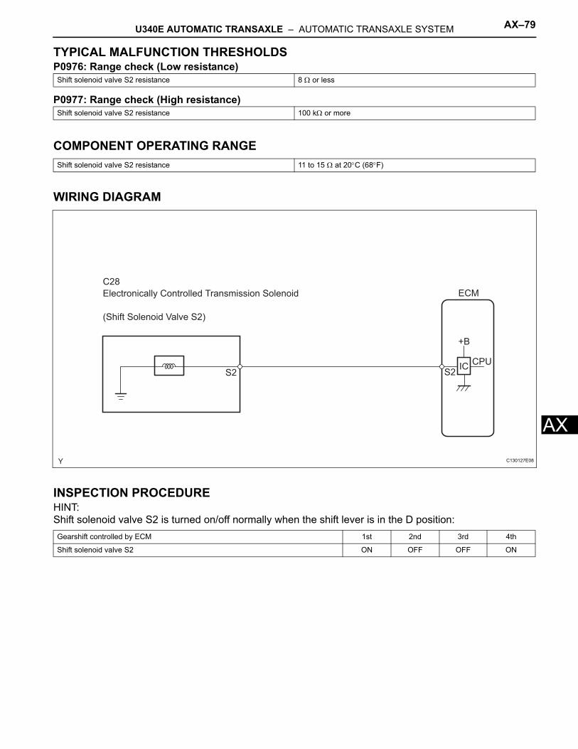
U340E AUTOMATIC TRANSAXLE – AUTOMATIC TRANSAXLE SYSTEM AX–79
X
ATYPICAL MALFUNCTION THRESHOLDSP0976: Range check (Low resistance)
P0977: Range check (High resistance)
COMPONENT OPERATING RANGE
WIRING DIAGRAM
INSPECTION PROCEDUREHINT:Shift solenoid valve S2 is turned on/off normally when the shift lever is in the D position:
Shift solenoid valve S2 resistance 8 Ω or less
Shift solenoid valve S2 resistance 100 kΩ or more
Shift solenoid valve S2 resistance 11 to 15 Ω at 20°C (68°F)
Gearshift controlled by ECM 1st 2nd 3rd 4th
Shift solenoid valve S2 ON OFF OFF ON
C28
Electronically Controlled Transmission Solenoid
(Shift Solenoid Valve S2)
S2IC
S2CPU
ECM
+B
C130127E08
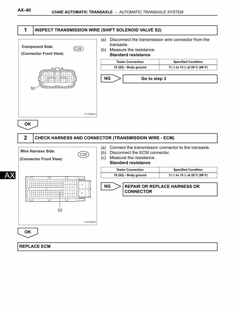
AX–80 U340E AUTOMATIC TRANSAXLE – AUTOMATIC TRANSAXLE SYSTEM
AX
(a) Disconnect the transmission wire connector from the transaxle.
(b) Measure the resistance.Standard resistance
NG
OK
(a) Connect the transmission connector to the transaxle.(b) Disconnect the ECM connector.(c) Measure the resistance.
Standard resistance
NG
OK
1 INSPECT TRANSMISSION WIRE (SHIFT SOLENOID VALVE S2)
C28
(Connector Front View)
Component Side:
S2
C117650E04
Tester Connection Specified Condition
10 (S2) - Body ground 11 Ω to 15 Ω at 20°C (68°F)
Go to step 3
2 CHECK HARNESS AND CONNECTOR (TRANSMISSION WIRE - ECM)
C20Wire Harness Side:
(Connector Front View)
S2
C130155E04
Tester Connection Specified Condition
78 (S2) - Body ground 11 Ω to 15 Ω at 20°C (68°F)
REPAIR OR REPLACE HARNESS OR CONNECTOR
REPLACE ECM
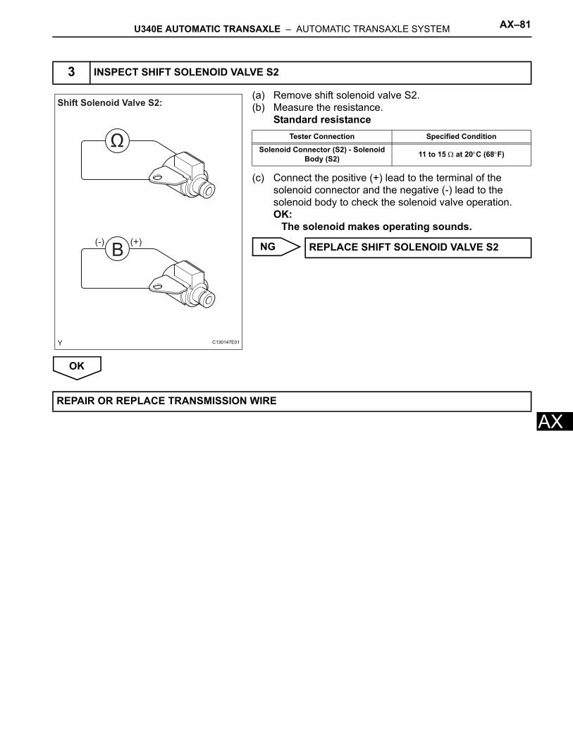
U340E AUTOMATIC TRANSAXLE – AUTOMATIC TRANSAXLE SYSTEM AX–81
X
A(a) Remove shift solenoid valve S2.(b) Measure the resistance.
Standard resistance
(c) Connect the positive (+) lead to the terminal of the solenoid connector and the negative (-) lead to the solenoid body to check the solenoid valve operation.OK:
The solenoid makes operating sounds.
NG
OK
3 INSPECT SHIFT SOLENOID VALVE S2
B
Ω
Shift Solenoid Valve S2:
(-) (+)
C130147E01
Tester Connection Specified Condition
Solenoid Connector (S2) - Solenoid Body (S2) 11 to 15 Ω at 20°C (68°F)
REPLACE SHIFT SOLENOID VALVE S2
REPAIR OR REPLACE TRANSMISSION WIRE
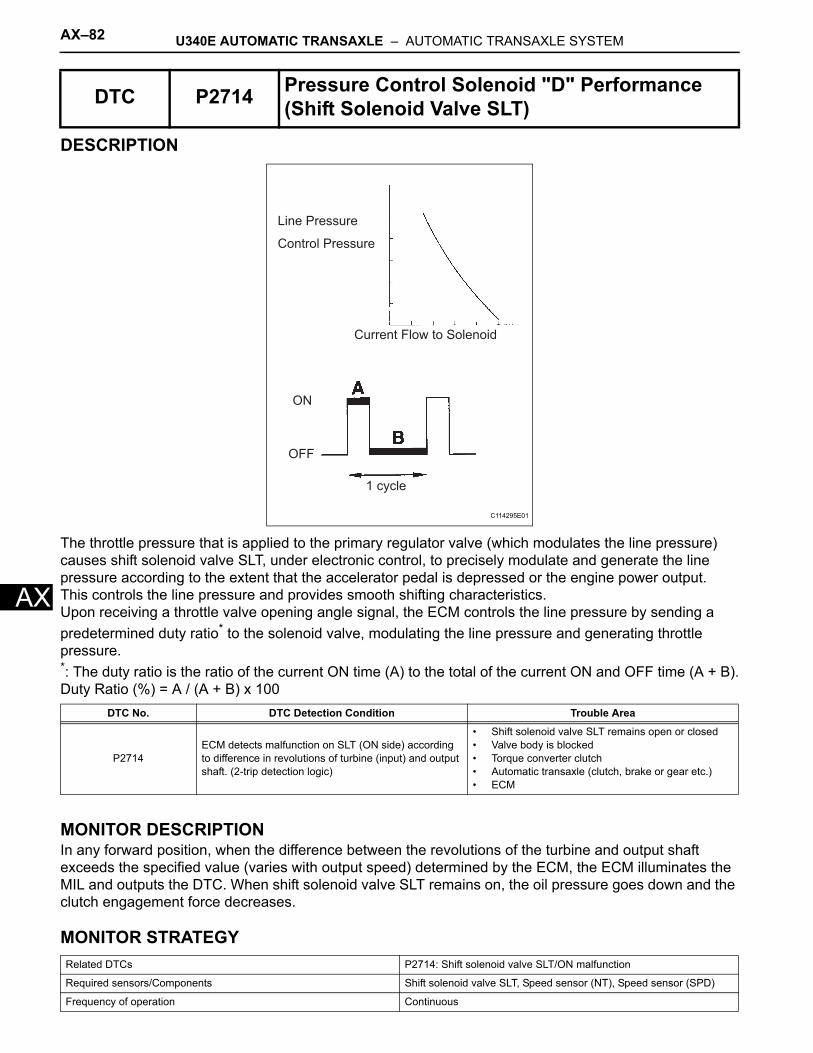
AX–82 U340E AUTOMATIC TRANSAXLE – AUTOMATIC TRANSAXLE SYSTEM
AX
DESCRIPTION
The throttle pressure that is applied to the primary regulator valve (which modulates the line pressure) causes shift solenoid valve SLT, under electronic control, to precisely modulate and generate the line pressure according to the extent that the accelerator pedal is depressed or the engine power output.This controls the line pressure and provides smooth shifting characteristics.Upon receiving a throttle valve opening angle signal, the ECM controls the line pressure by sending a predetermined duty ratio* to the solenoid valve, modulating the line pressure and generating throttle pressure.*: The duty ratio is the ratio of the current ON time (A) to the total of the current ON and OFF time (A + B).Duty Ratio (%) = A / (A + B) x 100
MONITOR DESCRIPTIONIn any forward position, when the difference between the revolutions of the turbine and output shaft exceeds the specified value (varies with output speed) determined by the ECM, the ECM illuminates the MIL and outputs the DTC. When shift solenoid valve SLT remains on, the oil pressure goes down and the clutch engagement force decreases.
MONITOR STRATEGY
DTC P2714 Pressure Control Solenoid "D" Performance (Shift Solenoid Valve SLT)
DTC No. DTC Detection Condition Trouble Area
P2714ECM detects malfunction on SLT (ON side) according to difference in revolutions of turbine (input) and output shaft. (2-trip detection logic)
• Shift solenoid valve SLT remains open or closed• Valve body is blocked• Torque converter clutch• Automatic transaxle (clutch, brake or gear etc.)• ECM
Related DTCs P2714: Shift solenoid valve SLT/ON malfunction
Required sensors/Components Shift solenoid valve SLT, Speed sensor (NT), Speed sensor (SPD)
Frequency of operation Continuous
Line Pressure
Control Pressure
Current Flow to Solenoid
ON
OFF
1 cycle
C114295E01
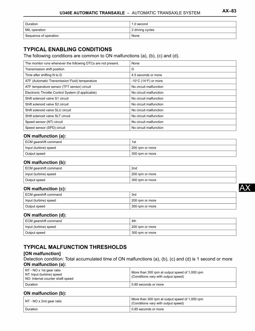
U340E AUTOMATIC TRANSAXLE – AUTOMATIC TRANSAXLE SYSTEM AX–83
X
ATYPICAL ENABLING CONDITIONSThe following conditions are common to ON malfunctions (a), (b), (c) and (d).
ON malfunction (a):
ON malfunction (b):
ON malfunction (c):
ON malfunction (d):
TYPICAL MALFUNCTION THRESHOLDS[ON malfunction]Detection condition: Total accumulated time of ON malfunctions (a), (b), (c) and (d) is 1 second or moreON malfunction (a):
ON malfunction (b):
Duration 1.0 second
MIL operation 2 driving cycles
Sequence of operation None
The monitor runs whenever the following DTCs are not present. None
Transmission shift position D
Time after shifting N to D 4.5 seconds or more
ATF (Automatic Transmission Fluid) temperature -10°C (14°F) or more
ATF temperature sensor (TFT sensor) circuit No circuit malfunction
Electronic Throttle Control System (if applicable) No circuit malfunction
Shift solenoid valve S1 circuit No circuit malfunction
Shift solenoid valve S2 circuit No circuit malfunction
Shift solenoid valve SLU circuit No circuit malfunction
Shift solenoid valve SLT circuit No circuit malfunction
Speed sensor (NT) circuit No circuit malfunction
Speed sensor (SPD) circuit No circuit malfunction
ECM gearshift command 1st
Input (turbine) speed 200 rpm or more
Output speed 300 rpm or more
ECM gearshift command 2nd
Input (turbine) speed 200 rpm or more
Output speed 300 rpm or more
ECM gearshift command 3rd
Input (turbine) speed 200 rpm or more
Output speed 300 rpm or more
ECM gearshift command 4th
Input (turbine) speed 200 rpm or more
Output speed 300 rpm or more
NT - NO x 1st gear ratioNT: Input (turbine) speedNO: Internal counter shaft speed
More than 300 rpm at output speed of 1,000 rpm(Conditions vary with output speed)
Duration 0.85 seconds or more
NT - NO x 2nd gear ratio More than 300 rpm at output speed of 1,000 rpm(Conditions vary with output speed)
Duration 0.85 seconds or more
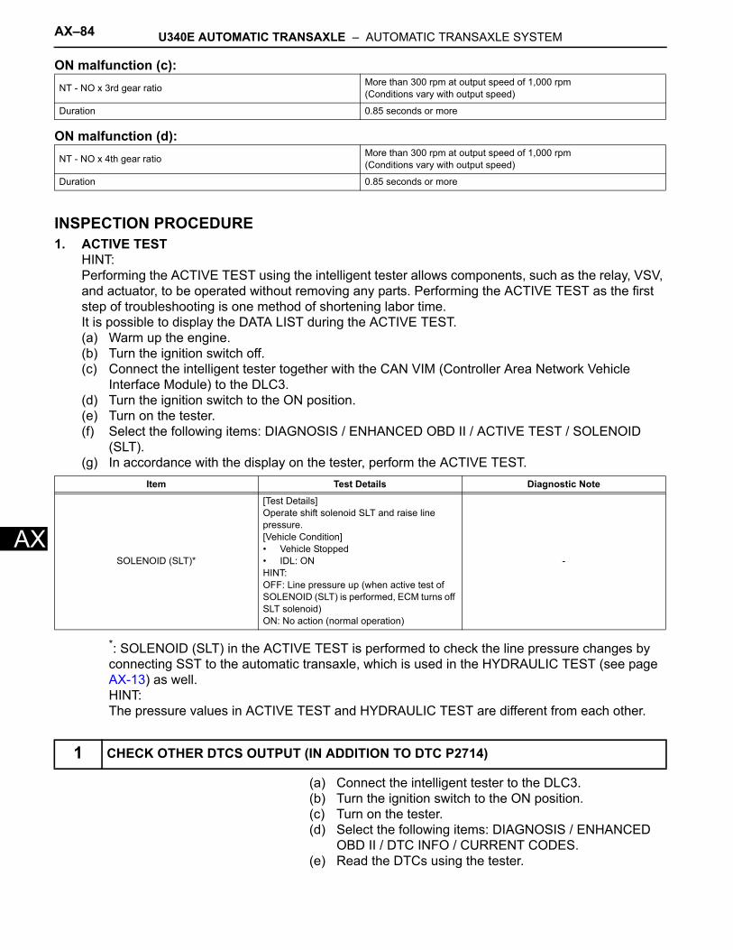
AX–84 U340E AUTOMATIC TRANSAXLE – AUTOMATIC TRANSAXLE SYSTEM
AX
ON malfunction (c):
ON malfunction (d):
INSPECTION PROCEDURE1. ACTIVE TEST
HINT:Performing the ACTIVE TEST using the intelligent tester allows components, such as the relay, VSV, and actuator, to be operated without removing any parts. Performing the ACTIVE TEST as the first step of troubleshooting is one method of shortening labor time.It is possible to display the DATA LIST during the ACTIVE TEST.(a) Warm up the engine.(b) Turn the ignition switch off.(c) Connect the intelligent tester together with the CAN VIM (Controller Area Network Vehicle
Interface Module) to the DLC3.(d) Turn the ignition switch to the ON position.(e) Turn on the tester.(f) Select the following items: DIAGNOSIS / ENHANCED OBD II / ACTIVE TEST / SOLENOID
(SLT).(g) In accordance with the display on the tester, perform the ACTIVE TEST.
*: SOLENOID (SLT) in the ACTIVE TEST is performed to check the line pressure changes by connecting SST to the automatic transaxle, which is used in the HYDRAULIC TEST (see page AX-13) as well.HINT:The pressure values in ACTIVE TEST and HYDRAULIC TEST are different from each other.
(a) Connect the intelligent tester to the DLC3.(b) Turn the ignition switch to the ON position.(c) Turn on the tester.(d) Select the following items: DIAGNOSIS / ENHANCED
OBD II / DTC INFO / CURRENT CODES.(e) Read the DTCs using the tester.
NT - NO x 3rd gear ratio More than 300 rpm at output speed of 1,000 rpm(Conditions vary with output speed)
Duration 0.85 seconds or more
NT - NO x 4th gear ratio More than 300 rpm at output speed of 1,000 rpm(Conditions vary with output speed)
Duration 0.85 seconds or more
Item Test Details Diagnostic Note
SOLENOID (SLT)*
[Test Details]Operate shift solenoid SLT and raise line pressure.[Vehicle Condition]• Vehicle Stopped• IDL: ONHINT:OFF: Line pressure up (when active test of SOLENOID (SLT) is performed, ECM turns off SLT solenoid)ON: No action (normal operation)
-
1 CHECK OTHER DTCS OUTPUT (IN ADDITION TO DTC P2714)
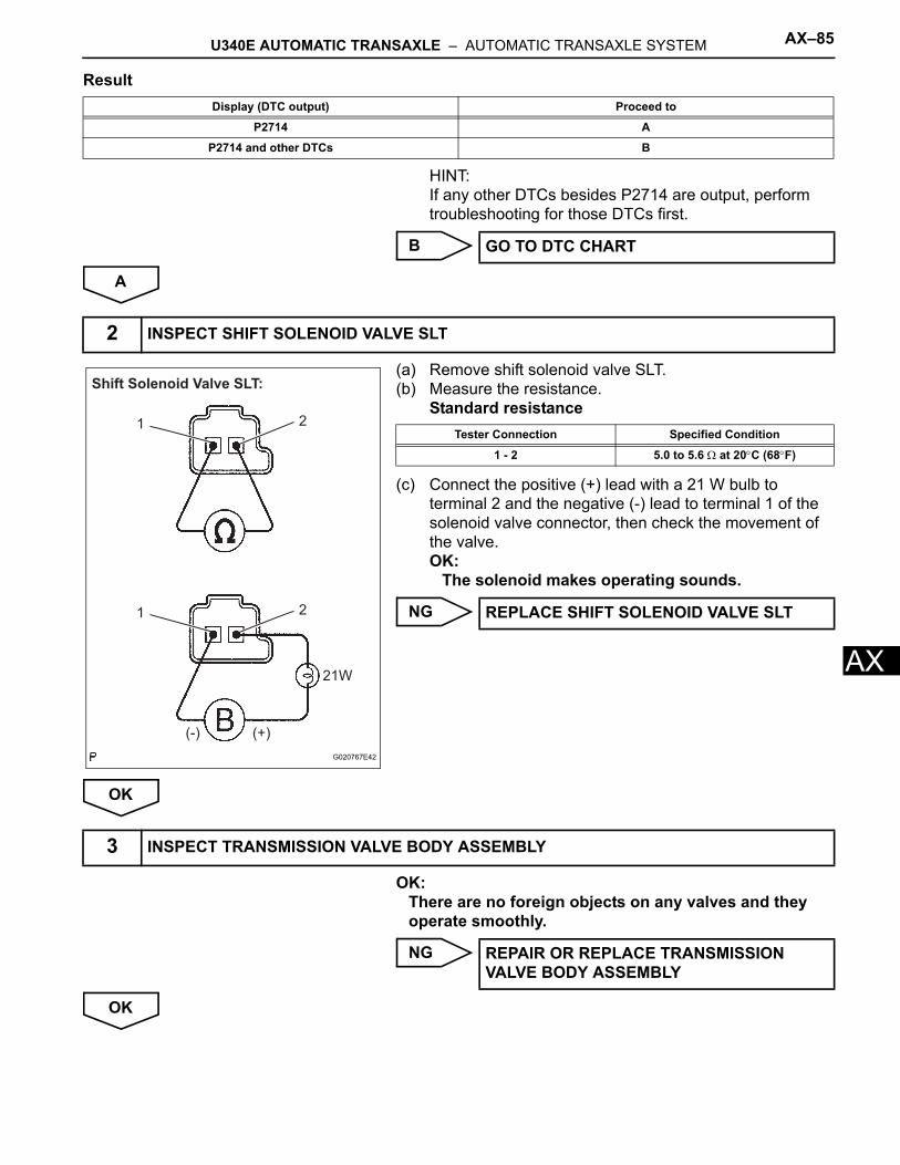
U340E AUTOMATIC TRANSAXLE – AUTOMATIC TRANSAXLE SYSTEM AX–85
X
AResult
HINT:If any other DTCs besides P2714 are output, perform troubleshooting for those DTCs first.
B
A
(a) Remove shift solenoid valve SLT.(b) Measure the resistance.
Standard resistance
(c) Connect the positive (+) lead with a 21 W bulb to terminal 2 and the negative (-) lead to terminal 1 of the solenoid valve connector, then check the movement of the valve.OK:
The solenoid makes operating sounds.
NG
OK
OK:There are no foreign objects on any valves and they operate smoothly.
NG
OK
Display (DTC output) Proceed to
P2714 A
P2714 and other DTCs B
GO TO DTC CHART
2 INSPECT SHIFT SOLENOID VALVE SLT
Shift Solenoid Valve SLT:
(-) (+)
21W
1 2
1 2
G020767E42
Tester Connection Specified Condition
1 - 2 5.0 to 5.6 Ω at 20°C (68°F)
REPLACE SHIFT SOLENOID VALVE SLT
3 INSPECT TRANSMISSION VALVE BODY ASSEMBLY
REPAIR OR REPLACE TRANSMISSION VALVE BODY ASSEMBLY
AX–86 U340E AUTOMATIC TRANSAXLE – AUTOMATIC TRANSAXLE SYSTEM
AX
OK:The torque converter clutch operates normally.
NG
OK
4 INSPECT TORQUE CONVERTER CLUTCH ASSEMBLY
REPLACE TORQUE CONVERTER CLUTCH ASSEMBLY
REPAIR OR REPLACE AUTOMATIC TRANSAXLE ASSEMBLY
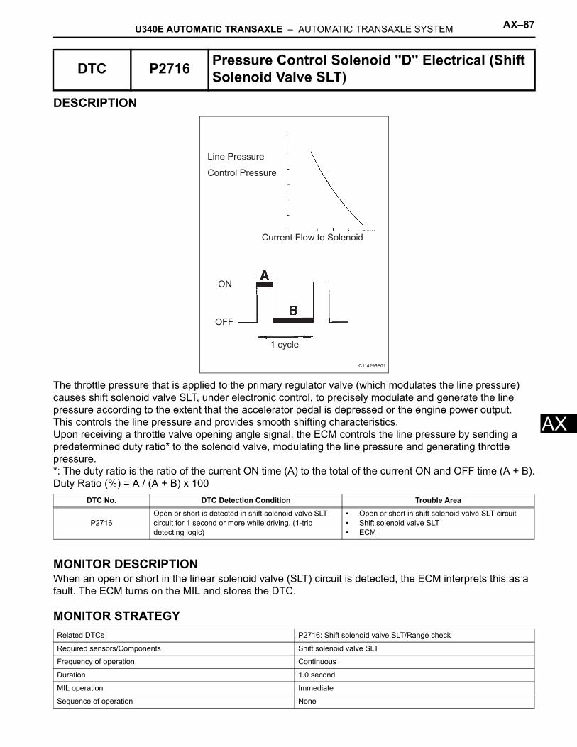
U340E AUTOMATIC TRANSAXLE – AUTOMATIC TRANSAXLE SYSTEM AX–87
X
ADESCRIPTION
The throttle pressure that is applied to the primary regulator valve (which modulates the line pressure) causes shift solenoid valve SLT, under electronic control, to precisely modulate and generate the line pressure according to the extent that the accelerator pedal is depressed or the engine power output.This controls the line pressure and provides smooth shifting characteristics.Upon receiving a throttle valve opening angle signal, the ECM controls the line pressure by sending a predetermined duty ratio* to the solenoid valve, modulating the line pressure and generating throttle pressure.*: The duty ratio is the ratio of the current ON time (A) to the total of the current ON and OFF time (A + B).Duty Ratio (%) = A / (A + B) x 100
MONITOR DESCRIPTIONWhen an open or short in the linear solenoid valve (SLT) circuit is detected, the ECM interprets this as a fault. The ECM turns on the MIL and stores the DTC.
MONITOR STRATEGY
DTC P2716 Pressure Control Solenoid "D" Electrical (Shift Solenoid Valve SLT)
DTC No. DTC Detection Condition Trouble Area
P2716Open or short is detected in shift solenoid valve SLT circuit for 1 second or more while driving. (1-trip detecting logic)
• Open or short in shift solenoid valve SLT circuit• Shift solenoid valve SLT• ECM
Related DTCs P2716: Shift solenoid valve SLT/Range check
Required sensors/Components Shift solenoid valve SLT
Frequency of operation Continuous
Duration 1.0 second
MIL operation Immediate
Sequence of operation None
Line Pressure
Control Pressure
Current Flow to Solenoid
ON
OFF
1 cycle
C114295E01
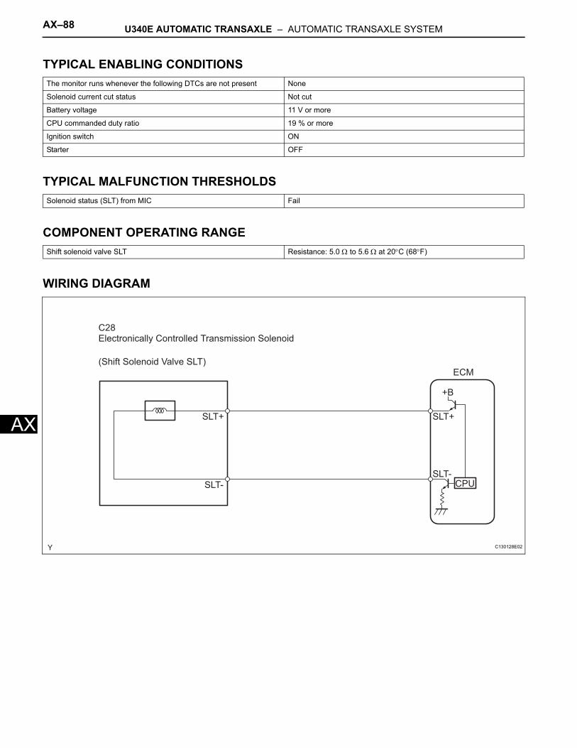
AX–88 U340E AUTOMATIC TRANSAXLE – AUTOMATIC TRANSAXLE SYSTEM
AX
TYPICAL ENABLING CONDITIONS
TYPICAL MALFUNCTION THRESHOLDS
COMPONENT OPERATING RANGE
WIRING DIAGRAM
The monitor runs whenever the following DTCs are not present None
Solenoid current cut status Not cut
Battery voltage 11 V or more
CPU commanded duty ratio 19 % or more
Ignition switch ON
Starter OFF
Solenoid status (SLT) from MIC Fail
Shift solenoid valve SLT Resistance: 5.0 Ω to 5.6 Ω at 20°C (68°F)
C28Electronically Controlled Transmission Solenoid
(Shift Solenoid Valve SLT)
SLT+
SLT-
ECM
+B
SLT+
SLT-CPU
C130128E02
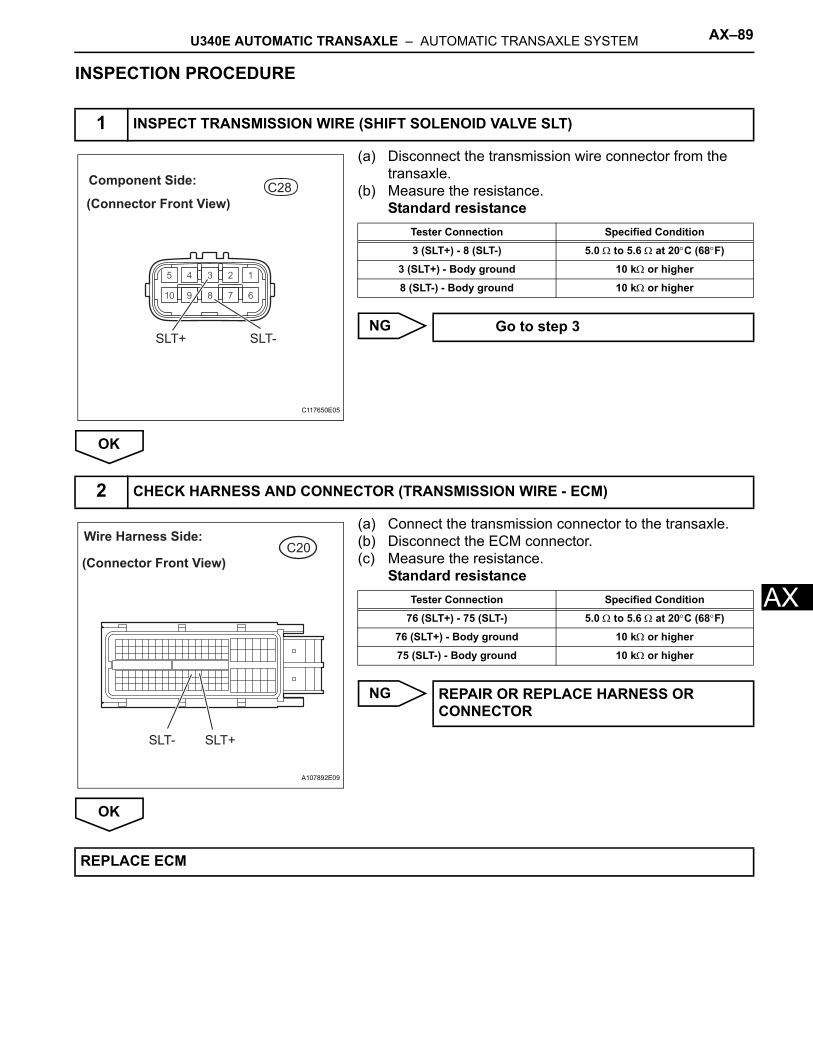
U340E AUTOMATIC TRANSAXLE – AUTOMATIC TRANSAXLE SYSTEM AX–89
X
AINSPECTION PROCEDURE
(a) Disconnect the transmission wire connector from the transaxle.
(b) Measure the resistance.Standard resistance
NG
OK
(a) Connect the transmission connector to the transaxle.(b) Disconnect the ECM connector.(c) Measure the resistance.
Standard resistance
NG
OK
1 INSPECT TRANSMISSION WIRE (SHIFT SOLENOID VALVE SLT)
C28
(Connector Front View)
Component Side:
SLT+ SLT-
C117650E05
Tester Connection Specified Condition
3 (SLT+) - 8 (SLT-) 5.0 Ω to 5.6 Ω at 20°C (68°F)
3 (SLT+) - Body ground 10 kΩ or higher
8 (SLT-) - Body ground 10 kΩ or higher
Go to step 3
2 CHECK HARNESS AND CONNECTOR (TRANSMISSION WIRE - ECM)
C20Wire Harness Side:
(Connector Front View)
SLT- SLT+
A107892E09
Tester Connection Specified Condition
76 (SLT+) - 75 (SLT-) 5.0 Ω to 5.6 Ω at 20°C (68°F)
76 (SLT+) - Body ground 10 kΩ or higher
75 (SLT-) - Body ground 10 kΩ or higher
REPAIR OR REPLACE HARNESS OR CONNECTOR
REPLACE ECM
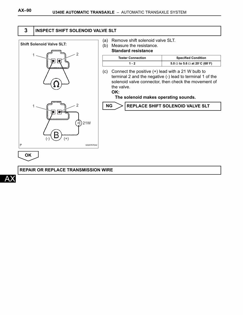
AX–90 U340E AUTOMATIC TRANSAXLE – AUTOMATIC TRANSAXLE SYSTEM
AX
(a) Remove shift solenoid valve SLT.(b) Measure the resistance.
Standard resistance
(c) Connect the positive (+) lead with a 21 W bulb to terminal 2 and the negative (-) lead to terminal 1 of the solenoid valve connector, then check the movement of the valve.OK:
The solenoid makes operating sounds.
NG
OK
3 INSPECT SHIFT SOLENOID VALVE SLT
Shift Solenoid Valve SLT:
(-) (+)
21W
1 2
1 2
G020767E42
Tester Connection Specified Condition
1 - 2 5.0 Ω to 5.6 Ω at 20°C (68°F)
REPLACE SHIFT SOLENOID VALVE SLT
REPAIR OR REPLACE TRANSMISSION WIRE
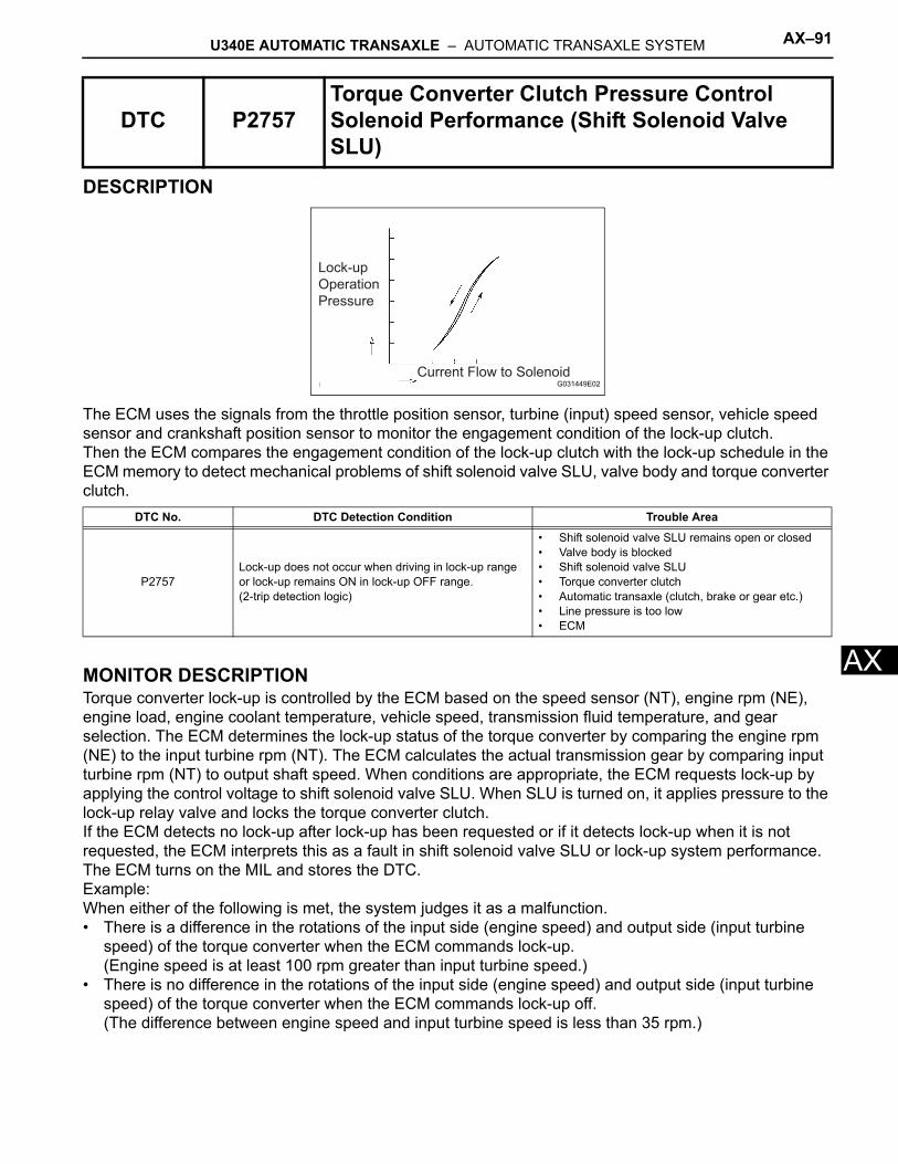
U340E AUTOMATIC TRANSAXLE – AUTOMATIC TRANSAXLE SYSTEM AX–91
X
ADESCRIPTION
The ECM uses the signals from the throttle position sensor, turbine (input) speed sensor, vehicle speed sensor and crankshaft position sensor to monitor the engagement condition of the lock-up clutch.Then the ECM compares the engagement condition of the lock-up clutch with the lock-up schedule in the ECM memory to detect mechanical problems of shift solenoid valve SLU, valve body and torque converter clutch.
MONITOR DESCRIPTIONTorque converter lock-up is controlled by the ECM based on the speed sensor (NT), engine rpm (NE), engine load, engine coolant temperature, vehicle speed, transmission fluid temperature, and gear selection. The ECM determines the lock-up status of the torque converter by comparing the engine rpm (NE) to the input turbine rpm (NT). The ECM calculates the actual transmission gear by comparing input turbine rpm (NT) to output shaft speed. When conditions are appropriate, the ECM requests lock-up by applying the control voltage to shift solenoid valve SLU. When SLU is turned on, it applies pressure to the lock-up relay valve and locks the torque converter clutch.If the ECM detects no lock-up after lock-up has been requested or if it detects lock-up when it is not requested, the ECM interprets this as a fault in shift solenoid valve SLU or lock-up system performance. The ECM turns on the MIL and stores the DTC.Example:When either of the following is met, the system judges it as a malfunction.• There is a difference in the rotations of the input side (engine speed) and output side (input turbine
speed) of the torque converter when the ECM commands lock-up.(Engine speed is at least 100 rpm greater than input turbine speed.)
• There is no difference in the rotations of the input side (engine speed) and output side (input turbine speed) of the torque converter when the ECM commands lock-up off.(The difference between engine speed and input turbine speed is less than 35 rpm.)
DTC P2757Torque Converter Clutch Pressure Control Solenoid Performance (Shift Solenoid Valve SLU)
DTC No. DTC Detection Condition Trouble Area
P2757Lock-up does not occur when driving in lock-up range or lock-up remains ON in lock-up OFF range.(2-trip detection logic)
• Shift solenoid valve SLU remains open or closed• Valve body is blocked• Shift solenoid valve SLU• Torque converter clutch• Automatic transaxle (clutch, brake or gear etc.)• Line pressure is too low• ECM
Lock-up
Operation
Pressure
Current Flow to SolenoidG031449E02
AX–92 U340E AUTOMATIC TRANSAXLE – AUTOMATIC TRANSAXLE SYSTEM
AX
MONITOR STRATEGY
TYPICAL ENABLING CONDITIONSThe following conditions are common to OFF malfunction and ON malfunction.
OFF malfunction:
ON malfunction:
TYPICAL MALFUNCTION THRESHOLDSOFF malfunction:
[ON malfunction]2 detections are necessary per driving cycle.1st detection: Temporary flag ON2nd detection: Pending fault code ONVehicle speed must be under 6.2 mph (10 km/h) once before 2nd detection.ON malfunction:
Related DTCsP2757:Shift solenoid valve SLU/OFF malfunctionShift solenoid valve SLU/ON malfunction
Required sensors/Components Shift solenoid valve SLU, Speed sensor (NT), Crankshaft position sensor (NE)
Frequency of operation Continuous
Duration OFF malfunction: 3.5 secondsON malfunction: 1.8 seconds
MIL operation 2 driving cycles
Sequence of operation None
The monitor runs whenever the following DTCs are not present. None
Time after shifting N to D 4.5 seconds or more
ECT (Engine Coolant Temperature) 60°C (140°F) or more
Transmission shift position D
ECM selected gear 3rd or 4th
Vehicle speed 15.5 mph (25 km/h) or more
Shift solenoid valve S1 circuit No circuit malfunction
Shift solenoid valve S2 circuit No circuit malfunction
Shift solenoid valve SLU circuit No circuit malfunction
ECT sensor circuit No circuit malfunction
Electronic Throttle Control System (if applicable) No circuit malfunction
Speed sensor (NT) circuit No circuit malfunction
Speed sensor (SPD) circuit No circuit malfunction
ECM lock-up command ON
Duration time from lock-up on command 3 seconds or more
Actual gear 3rd or 4th
ECM lock-up command OFF
Throttle valve opening angle 8 % or more
Vehicle speed Less than 37.3 mph (60 km/h)
Actual gear 3rd
Calculated load value 22 % or more
Engine speed - Input (turbine) speed (NE - NT) 100 rpm or more
Difference between engine speed and Input (turbine) speed Less than 35 rpm
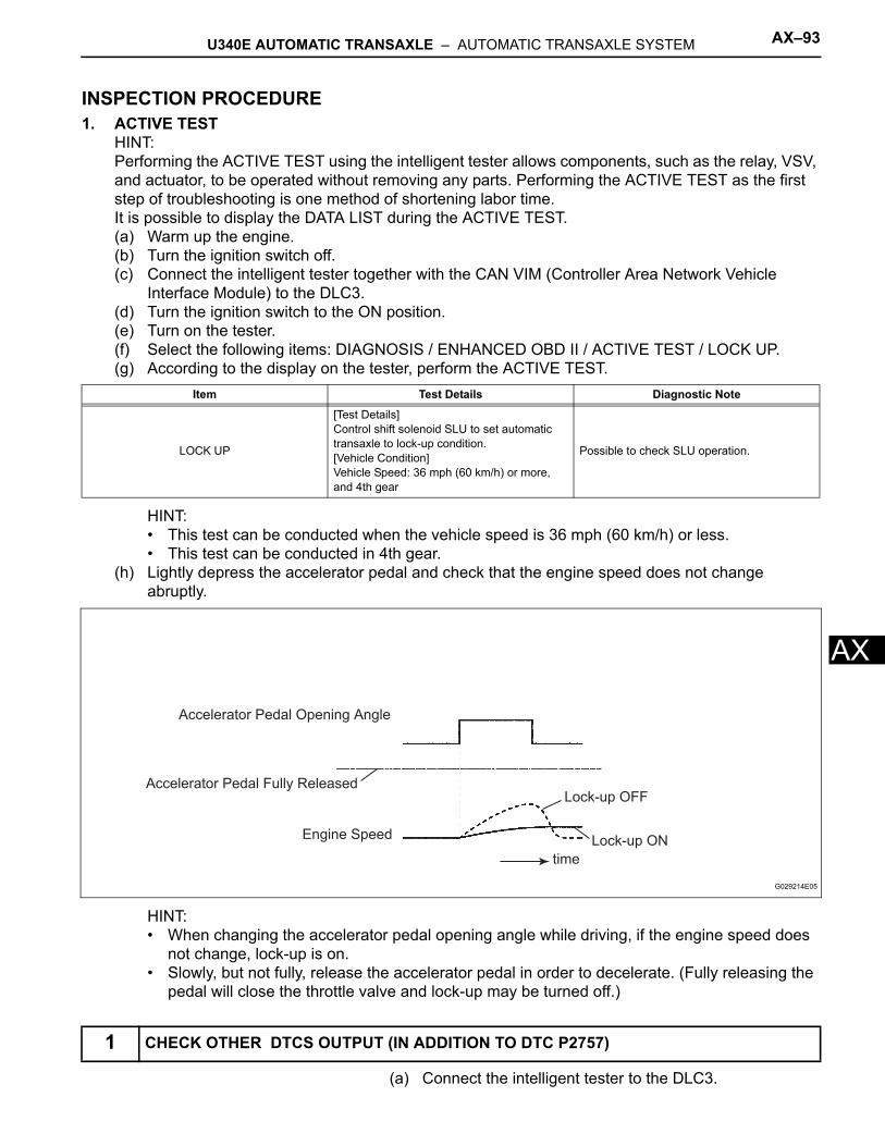
U340E AUTOMATIC TRANSAXLE – AUTOMATIC TRANSAXLE SYSTEM AX–93
X
AINSPECTION PROCEDURE1. ACTIVE TEST
HINT:Performing the ACTIVE TEST using the intelligent tester allows components, such as the relay, VSV, and actuator, to be operated without removing any parts. Performing the ACTIVE TEST as the first step of troubleshooting is one method of shortening labor time.It is possible to display the DATA LIST during the ACTIVE TEST.(a) Warm up the engine.(b) Turn the ignition switch off.(c) Connect the intelligent tester together with the CAN VIM (Controller Area Network Vehicle
Interface Module) to the DLC3.(d) Turn the ignition switch to the ON position.(e) Turn on the tester.(f) Select the following items: DIAGNOSIS / ENHANCED OBD II / ACTIVE TEST / LOCK UP.(g) According to the display on the tester, perform the ACTIVE TEST.
HINT:• This test can be conducted when the vehicle speed is 36 mph (60 km/h) or less.• This test can be conducted in 4th gear.
(h) Lightly depress the accelerator pedal and check that the engine speed does not change abruptly.
HINT:• When changing the accelerator pedal opening angle while driving, if the engine speed does
not change, lock-up is on.• Slowly, but not fully, release the accelerator pedal in order to decelerate. (Fully releasing the
pedal will close the throttle valve and lock-up may be turned off.)
(a) Connect the intelligent tester to the DLC3.
Item Test Details Diagnostic Note
LOCK UP
[Test Details]Control shift solenoid SLU to set automatic transaxle to lock-up condition.[Vehicle Condition]Vehicle Speed: 36 mph (60 km/h) or more, and 4th gear
Possible to check SLU operation.
1 CHECK OTHER DTCS OUTPUT (IN ADDITION TO DTC P2757)
Lock-up OFF
Lock-up ONEngine Speed
Accelerator Pedal Fully Released
Accelerator Pedal Opening Angle
time
G029214E05
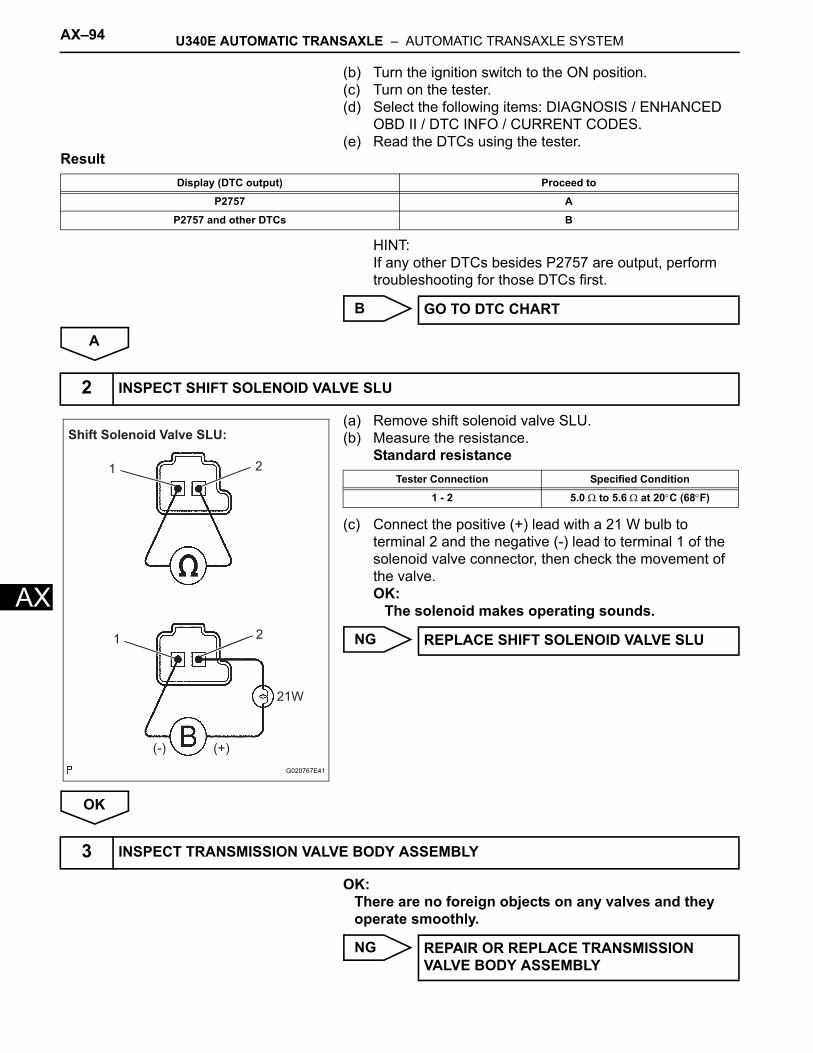
AX–94 U340E AUTOMATIC TRANSAXLE – AUTOMATIC TRANSAXLE SYSTEM
AX
(b) Turn the ignition switch to the ON position.(c) Turn on the tester.(d) Select the following items: DIAGNOSIS / ENHANCED
OBD II / DTC INFO / CURRENT CODES.(e) Read the DTCs using the tester.
Result
HINT:If any other DTCs besides P2757 are output, perform troubleshooting for those DTCs first.
B
A
(a) Remove shift solenoid valve SLU.(b) Measure the resistance.
Standard resistance
(c) Connect the positive (+) lead with a 21 W bulb to terminal 2 and the negative (-) lead to terminal 1 of the solenoid valve connector, then check the movement of the valve.OK:
The solenoid makes operating sounds.
NG
OK
OK:There are no foreign objects on any valves and they operate smoothly.
NG
Display (DTC output) Proceed to
P2757 A
P2757 and other DTCs B
GO TO DTC CHART
2 INSPECT SHIFT SOLENOID VALVE SLU
Shift Solenoid Valve SLU:
1 2
21
(-) (+)
21W
G020767E41
Tester Connection Specified Condition
1 - 2 5.0 Ω to 5.6 Ω at 20°C (68°F)
REPLACE SHIFT SOLENOID VALVE SLU
3 INSPECT TRANSMISSION VALVE BODY ASSEMBLY
REPAIR OR REPLACE TRANSMISSION VALVE BODY ASSEMBLY
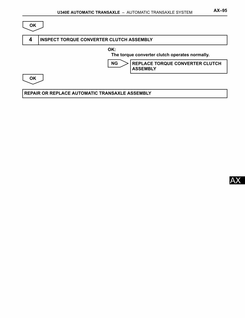
U340E AUTOMATIC TRANSAXLE – AUTOMATIC TRANSAXLE SYSTEM AX–95
X
AOK
OK:The torque converter clutch operates normally.
NG
OK
4 INSPECT TORQUE CONVERTER CLUTCH ASSEMBLY
REPLACE TORQUE CONVERTER CLUTCH ASSEMBLY
REPAIR OR REPLACE AUTOMATIC TRANSAXLE ASSEMBLY
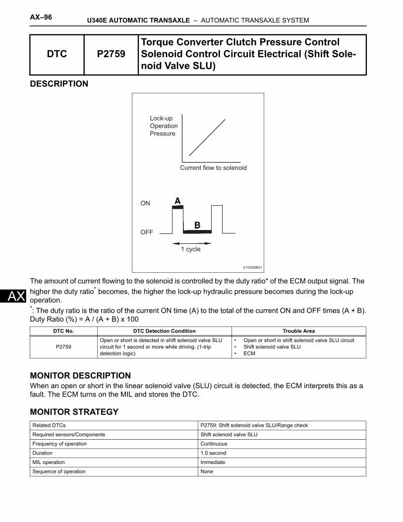
AX–96 U340E AUTOMATIC TRANSAXLE – AUTOMATIC TRANSAXLE SYSTEM
AX
DESCRIPTION
The amount of current flowing to the solenoid is controlled by the duty ratio* of the ECM output signal. The higher the duty ratio* becomes, the higher the lock-up hydraulic pressure becomes during the lock-up operation.*: The duty ratio is the ratio of the current ON time (A) to the total of the current ON and OFF times (A + B).Duty Ratio (%) = A / (A + B) x 100
MONITOR DESCRIPTIONWhen an open or short in the linear solenoid valve (SLU) circuit is detected, the ECM interprets this as a fault. The ECM turns on the MIL and stores the DTC.
MONITOR STRATEGY
DTC P2759Torque Converter Clutch Pressure Control Solenoid Control Circuit Electrical (Shift Sole-noid Valve SLU)
DTC No. DTC Detection Condition Trouble Area
P2759Open or short is detected in shift solenoid valve SLU circuit for 1 second or more while driving. (1-trip detection logic)
• Open or short in shift solenoid valve SLU circuit• Shift solenoid valve SLU• ECM
Related DTCs P2759: Shift solenoid valve SLU/Range check
Required sensors/Components Shift solenoid valve SLU
Frequency of operation Continuous
Duration 1.0 second
MIL operation Immediate
Sequence of operation None
Lock-up
Operation
Pressure
Current fiow to solenoid
ON
OFF
1 cycle
C110339E01
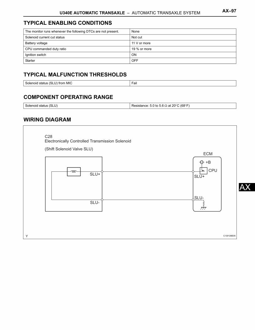
U340E AUTOMATIC TRANSAXLE – AUTOMATIC TRANSAXLE SYSTEM AX–97
X
ATYPICAL ENABLING CONDITIONS
TYPICAL MALFUNCTION THRESHOLDS
COMPONENT OPERATING RANGE
WIRING DIAGRAM
The monitor runs whenever the following DTCs are not present. None
Solenoid current cut status Not cut
Battery voltage 11 V or more
CPU commanded duty ratio 19 % or more
Ignition switch ON
Starter OFF
Solenoid status (SLU) from MIC Fail
Solenoid status (SLU) Resistance: 5.0 to 5.6 Ω at 20°C (68°F)
Electronically Controlled Transmission Solenoid
(Shift Solenoid Valve SLU)
SLU+
SLU-
SLU+
SLU-
CPU
+B
ECM
C28
C130126E05
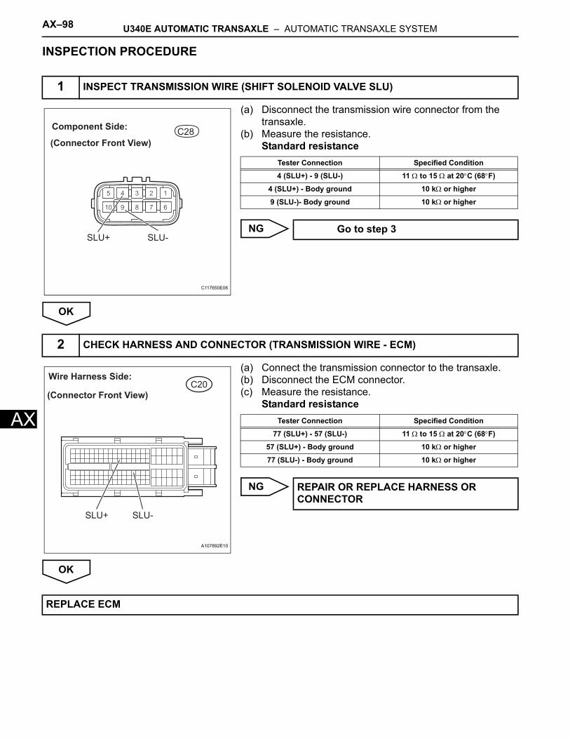
AX–98 U340E AUTOMATIC TRANSAXLE – AUTOMATIC TRANSAXLE SYSTEM
AX
INSPECTION PROCEDURE
(a) Disconnect the transmission wire connector from the transaxle.
(b) Measure the resistance.Standard resistance
NG
OK
(a) Connect the transmission connector to the transaxle.(b) Disconnect the ECM connector.(c) Measure the resistance.
Standard resistance
NG
OK
1 INSPECT TRANSMISSION WIRE (SHIFT SOLENOID VALVE SLU)
C28
(Connector Front View)
Component Side:
SLU+ SLU-
C117650E06
Tester Connection Specified Condition
4 (SLU+) - 9 (SLU-) 11 Ω to 15 Ω at 20°C (68°F)
4 (SLU+) - Body ground 10 kΩ or higher
9 (SLU-)- Body ground 10 kΩ or higher
Go to step 3
2 CHECK HARNESS AND CONNECTOR (TRANSMISSION WIRE - ECM)
C20Wire Harness Side:
(Connector Front View)
SLU-SLU+
A107892E10
Tester Connection Specified Condition
77 (SLU+) - 57 (SLU-) 11 Ω to 15 Ω at 20°C (68°F)
57 (SLU+) - Body ground 10 kΩ or higher
77 (SLU-) - Body ground 10 kΩ or higher
REPAIR OR REPLACE HARNESS OR CONNECTOR
REPLACE ECM
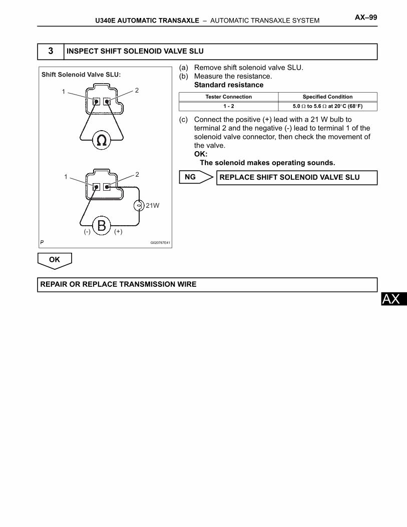
U340E AUTOMATIC TRANSAXLE – AUTOMATIC TRANSAXLE SYSTEM AX–99
X
A(a) Remove shift solenoid valve SLU.(b) Measure the resistance.
Standard resistance
(c) Connect the positive (+) lead with a 21 W bulb to terminal 2 and the negative (-) lead to terminal 1 of the solenoid valve connector, then check the movement of the valve.OK:
The solenoid makes operating sounds.
NG
OK
3 INSPECT SHIFT SOLENOID VALVE SLU
Shift Solenoid Valve SLU:
1 2
21
(-) (+)
21W
G020767E41
Tester Connection Specified Condition
1 - 2 5.0 Ω to 5.6 Ω at 20°C (68°F)
REPLACE SHIFT SOLENOID VALVE SLU
REPAIR OR REPLACE TRANSMISSION WIRE
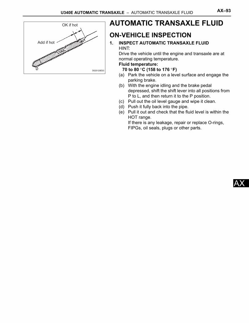
U340E AUTOMATIC TRANSAXLE – AUTOMATIC TRANSAXLE FLUID AX–93
AX
AUTOMATIC TRANSAXLE FLUIDON-VEHICLE INSPECTION1. INSPECT AUTOMATIC TRANSAXLE FLUID
HINT:Drive the vehicle until the engine and transaxle are at normal operating temperature.Fluid temperature:
70 to 80 °C (158 to 176 °F)(a) Park the vehicle on a level surface and engage the
parking brake.(b) With the engine idling and the brake pedal
depressed, shift the shift lever into all positions from P to L, and then return it to the P position.
(c) Pull out the oil level gauge and wipe it clean.(d) Push it fully back into the pipe.(e) Pull it out and check that the fluid level is within the
HOT range.If there is any leakage, repair or replace O-rings, FIPGs, oil seals, plugs or other parts.
OK if hot
Add if hot
D025120E03
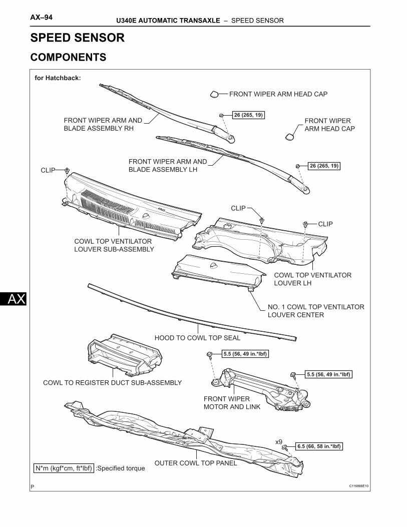
AX–94 U340E AUTOMATIC TRANSAXLE – SPEED SENSOR
AX
TRANSMISSIONU340E AUTOMATIC TRANSAXLESPEED SENSORCOMPONENTS
FRONT WIPER ARM HEAD CAP
FRONT WIPER
MOTOR AND LINK
FRONT WIPER
ARM HEAD CAP
FRONT WIPER ARM AND
BLADE ASSEMBLY LH
FRONT WIPER ARM AND
BLADE ASSEMBLY RH
N*m (kgf*cm, ft*lbf) :Specified torque
5.5 (56, 49 in.*lbf)
26 (265, 19)
26 (265, 19)
5.5 (56, 49 in.*lbf)
x96.5 (66, 58 in.*lbf)
CLIP
CLIP
CLIP
for Hatchback:
NO. 1 COWL TOP VENTILATOR
LOUVER CENTER
COWL TOP VENTILATOR
LOUVER LH
COWL TOP VENTILATOR
LOUVER SUB-ASSEMBLY
HOOD TO COWL TOP SEAL
COWL TO REGISTER DUCT SUB-ASSEMBLY
OUTER COWL TOP PANEL
C116866E10
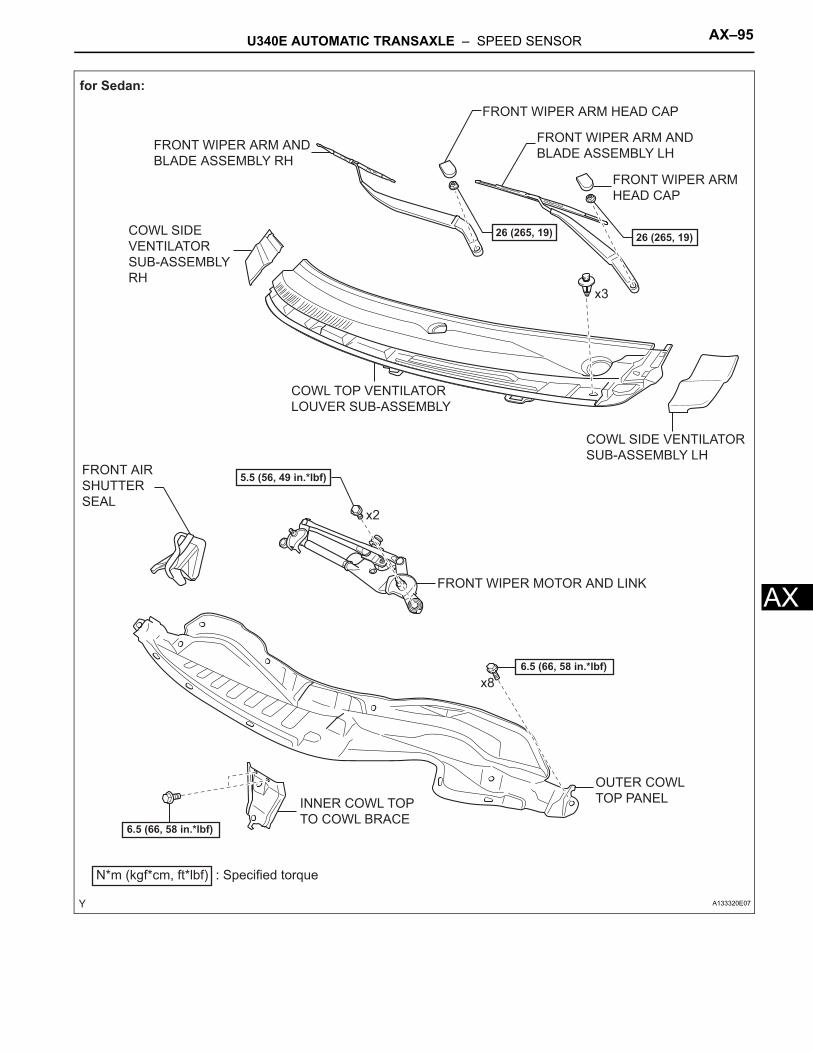
U340E AUTOMATIC TRANSAXLE – SPEED SENSOR AX–95
X
A6.5 (66, 58 in.*lbf)
6.5 (66, 58 in.*lbf)
for Sedan:
N*m (kgf*cm, ft*lbf) : Specified torque
x2
x8
5.5 (56, 49 in.*lbf)
x3
26 (265, 19)
INNER COWL TOP
TO COWL BRACE
26 (265, 19)
COWL SIDE VENTILATOR
SUB-ASSEMBLY LH
COWL SIDE
VENTILATOR
SUB-ASSEMBLY
RH
COWL TOP VENTILATOR
LOUVER SUB-ASSEMBLY
FRONT AIR
SHUTTER
SEAL
FRONT WIPER ARM AND
BLADE ASSEMBLY LHFRONT WIPER ARM AND
BLADE ASSEMBLY RH
FRONT WIPER ARM HEAD CAP
FRONT WIPER MOTOR AND LINK
OUTER COWL
TOP PANEL
FRONT WIPER ARM
HEAD CAP
A133320E07
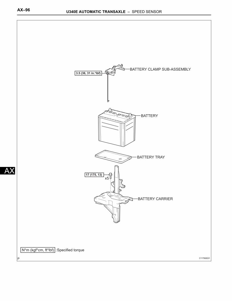
AX–96 U340E AUTOMATIC TRANSAXLE – SPEED SENSOR
AX
N*m (kgf*cm, ft*lbf) :Specified torque
3.5 (36, 31 in.*lbf)
17 (175, 13)x5
BATTERY CLAMP SUB-ASSEMBLY
BATTERY
BATTERY TRAY
BATTERY CARRIER
C117082E01
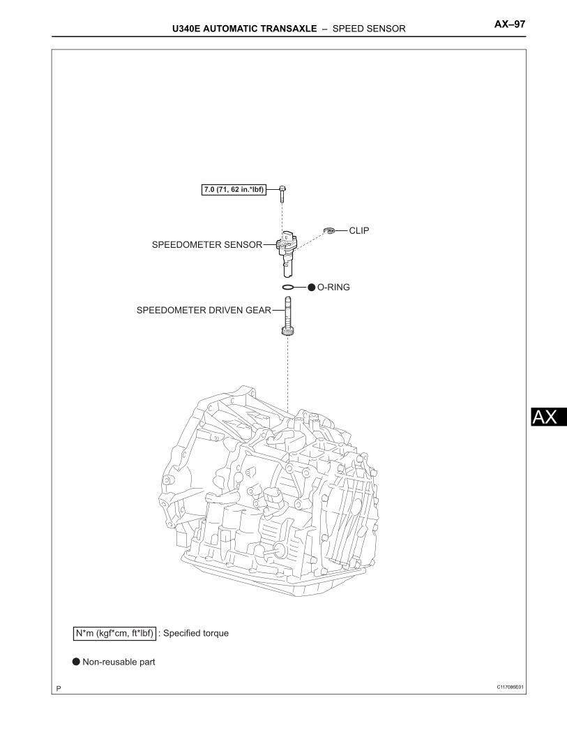
U340E AUTOMATIC TRANSAXLE – SPEED SENSOR AX–97
X
ASPEEDOMETER DRIVEN GEAR
SPEEDOMETER SENSOR
O-RING
CLIP
7.0 (71, 62 in.*lbf)
N*m (kgf*cm, ft*lbf) : Specified torque
Non-reusable part
C117086E01
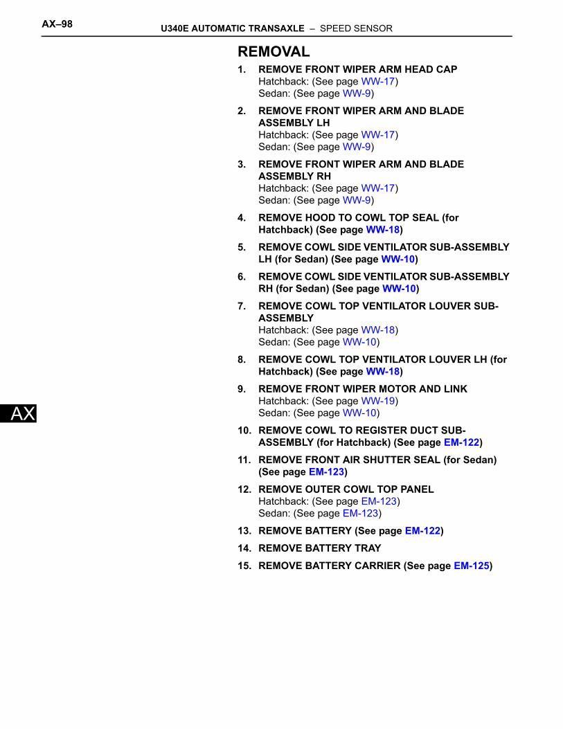
AX–98 U340E AUTOMATIC TRANSAXLE – SPEED SENSOR
AX
REMOVAL1. REMOVE FRONT WIPER ARM HEAD CAP
Hatchback: (See page WW-17)Sedan: (See page WW-9)
2. REMOVE FRONT WIPER ARM AND BLADE ASSEMBLY LHHatchback: (See page WW-17)Sedan: (See page WW-9)
3. REMOVE FRONT WIPER ARM AND BLADE ASSEMBLY RHHatchback: (See page WW-17)Sedan: (See page WW-9)
4. REMOVE HOOD TO COWL TOP SEAL (for Hatchback) (See page WW-18)
5. REMOVE COWL SIDE VENTILATOR SUB-ASSEMBLY LH (for Sedan) (See page WW-10)
6. REMOVE COWL SIDE VENTILATOR SUB-ASSEMBLY RH (for Sedan) (See page WW-10)
7. REMOVE COWL TOP VENTILATOR LOUVER SUB-ASSEMBLYHatchback: (See page WW-18)Sedan: (See page WW-10)
8. REMOVE COWL TOP VENTILATOR LOUVER LH (for Hatchback) (See page WW-18)
9. REMOVE FRONT WIPER MOTOR AND LINKHatchback: (See page WW-19)Sedan: (See page WW-10)
10. REMOVE COWL TO REGISTER DUCT SUB-ASSEMBLY (for Hatchback) (See page EM-122)
11. REMOVE FRONT AIR SHUTTER SEAL (for Sedan) (See page EM-123)
12. REMOVE OUTER COWL TOP PANELHatchback: (See page EM-123)Sedan: (See page EM-123)
13. REMOVE BATTERY (See page EM-122)14. REMOVE BATTERY TRAY15. REMOVE BATTERY CARRIER (See page EM-125)
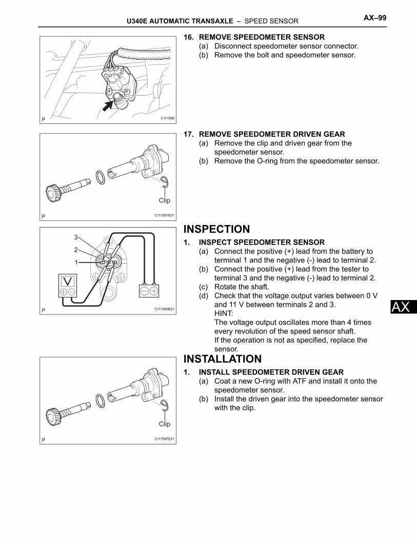
U340E AUTOMATIC TRANSAXLE – SPEED SENSOR AX–99
X
A16. REMOVE SPEEDOMETER SENSOR(a) Disconnect speedometer sensor connector.(b) Remove the bolt and speedometer sensor.
17. REMOVE SPEEDOMETER DRIVEN GEAR(a) Remove the clip and driven gear from the
speedometer sensor.(b) Remove the O-ring from the speedometer sensor.
INSPECTION1. INSPECT SPEEDOMETER SENSOR
(a) Connect the positive (+) lead from the battery to terminal 1 and the negative (-) lead to terminal 2.
(b) Connect the positive (+) lead from the tester to terminal 3 and the negative (-) lead to terminal 2.
(c) Rotate the shaft.(d) Check that the voltage output varies between 0 V
and 11 V between terminals 2 and 3.HINT:The voltage output oscillates more than 4 times every revolution of the speed sensor shaft.If the operation is not as specified, replace the sensor.
INSTALLATION1. INSTALL SPEEDOMETER DRIVEN GEAR
(a) Coat a new O-ring with ATF and install it onto the speedometer sensor.
(b) Install the driven gear into the speedometer sensor with the clip.
C117096
Clip
C117097E01
1
2
3
C117095E01
Clip
C117097E01
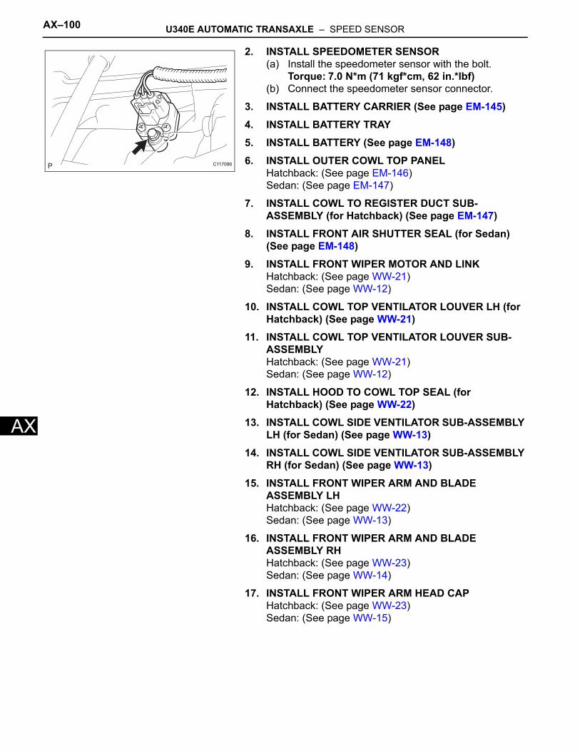
AX–100 U340E AUTOMATIC TRANSAXLE – SPEED SENSOR
AX
2. INSTALL SPEEDOMETER SENSOR(a) Install the speedometer sensor with the bolt.
Torque: 7.0 N*m (71 kgf*cm, 62 in.*lbf)(b) Connect the speedometer sensor connector.
3. INSTALL BATTERY CARRIER (See page EM-145)4. INSTALL BATTERY TRAY5. INSTALL BATTERY (See page EM-148)6. INSTALL OUTER COWL TOP PANEL
Hatchback: (See page EM-146)Sedan: (See page EM-147)
7. INSTALL COWL TO REGISTER DUCT SUB-ASSEMBLY (for Hatchback) (See page EM-147)
8. INSTALL FRONT AIR SHUTTER SEAL (for Sedan) (See page EM-148)
9. INSTALL FRONT WIPER MOTOR AND LINKHatchback: (See page WW-21)Sedan: (See page WW-12)
10. INSTALL COWL TOP VENTILATOR LOUVER LH (for Hatchback) (See page WW-21)
11. INSTALL COWL TOP VENTILATOR LOUVER SUB-ASSEMBLYHatchback: (See page WW-21)Sedan: (See page WW-12)
12. INSTALL HOOD TO COWL TOP SEAL (for Hatchback) (See page WW-22)
13. INSTALL COWL SIDE VENTILATOR SUB-ASSEMBLY LH (for Sedan) (See page WW-13)
14. INSTALL COWL SIDE VENTILATOR SUB-ASSEMBLY RH (for Sedan) (See page WW-13)
15. INSTALL FRONT WIPER ARM AND BLADE ASSEMBLY LHHatchback: (See page WW-22)Sedan: (See page WW-13)
16. INSTALL FRONT WIPER ARM AND BLADE ASSEMBLY RHHatchback: (See page WW-23)Sedan: (See page WW-14)
17. INSTALL FRONT WIPER ARM HEAD CAPHatchback: (See page WW-23)Sedan: (See page WW-15)
C117096
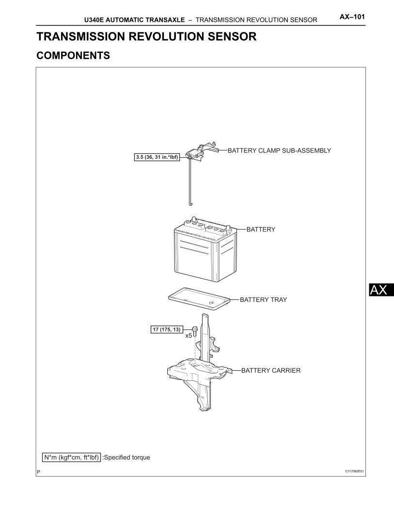
U340E AUTOMATIC TRANSAXLE – TRANSMISSION REVOLUTION SENSOR AX–101
X
ATRANSMISSIONU340E AUTOMATIC TRANSAXLETRANSMISSION REVOLUTION SENSORCOMPONENTS
N*m (kgf*cm, ft*lbf) :Specified torque
3.5 (36, 31 in.*lbf)
17 (175, 13)x5
BATTERY CLAMP SUB-ASSEMBLY
BATTERY
BATTERY TRAY
BATTERY CARRIER
C117082E01
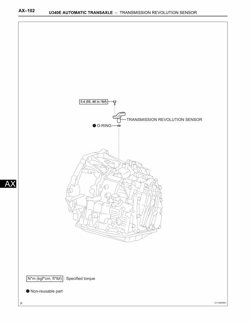
AX–102 U340E AUTOMATIC TRANSAXLE – TRANSMISSION REVOLUTION SENSOR
AX
TRANSMISSION REVOLUTION SENSOR
O-RING
5.4 (55, 48 in.*lbf)
N*m (kgf*cm, ft*lbf) : Specified torque
Non-reusable part
C117087E01
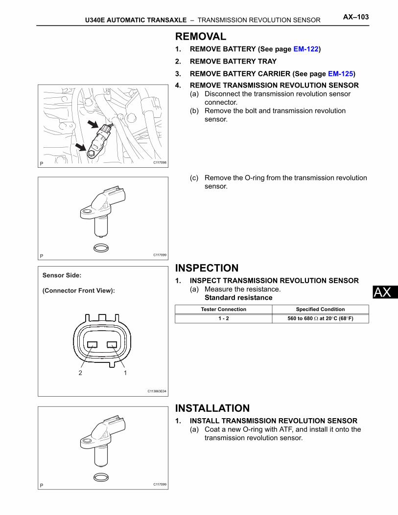
U340E AUTOMATIC TRANSAXLE – TRANSMISSION REVOLUTION SENSOR AX–103
X
AREMOVAL1. REMOVE BATTERY (See page EM-122)2. REMOVE BATTERY TRAY3. REMOVE BATTERY CARRIER (See page EM-125)4. REMOVE TRANSMISSION REVOLUTION SENSOR
(a) Disconnect the transmission revolution sensor connector.
(b) Remove the bolt and transmission revolution sensor.
(c) Remove the O-ring from the transmission revolution sensor.
INSPECTION1. INSPECT TRANSMISSION REVOLUTION SENSOR
(a) Measure the resistance.Standard resistance
INSTALLATION1. INSTALL TRANSMISSION REVOLUTION SENSOR
(a) Coat a new O-ring with ATF, and install it onto the transmission revolution sensor.
C117098
C117099
Sensor Side:
(Connector Front View):
12
C113863E04
Tester Connection Specified Condition
1 - 2 560 to 680 Ω at 20°C (68°F)
C117099
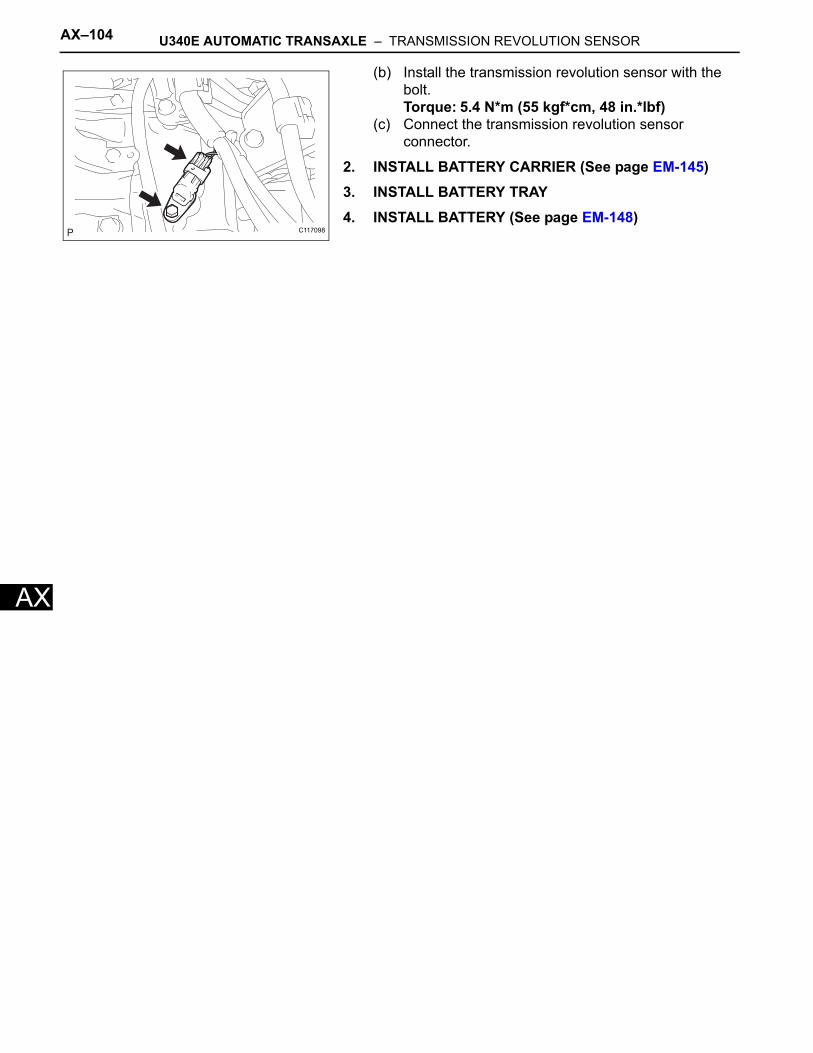
AX–104 U340E AUTOMATIC TRANSAXLE – TRANSMISSION REVOLUTION SENSOR
AX
(b) Install the transmission revolution sensor with the bolt.Torque: 5.4 N*m (55 kgf*cm, 48 in.*lbf)
(c) Connect the transmission revolution sensor connector.
2. INSTALL BATTERY CARRIER (See page EM-145)3. INSTALL BATTERY TRAY4. INSTALL BATTERY (See page EM-148)
C117098
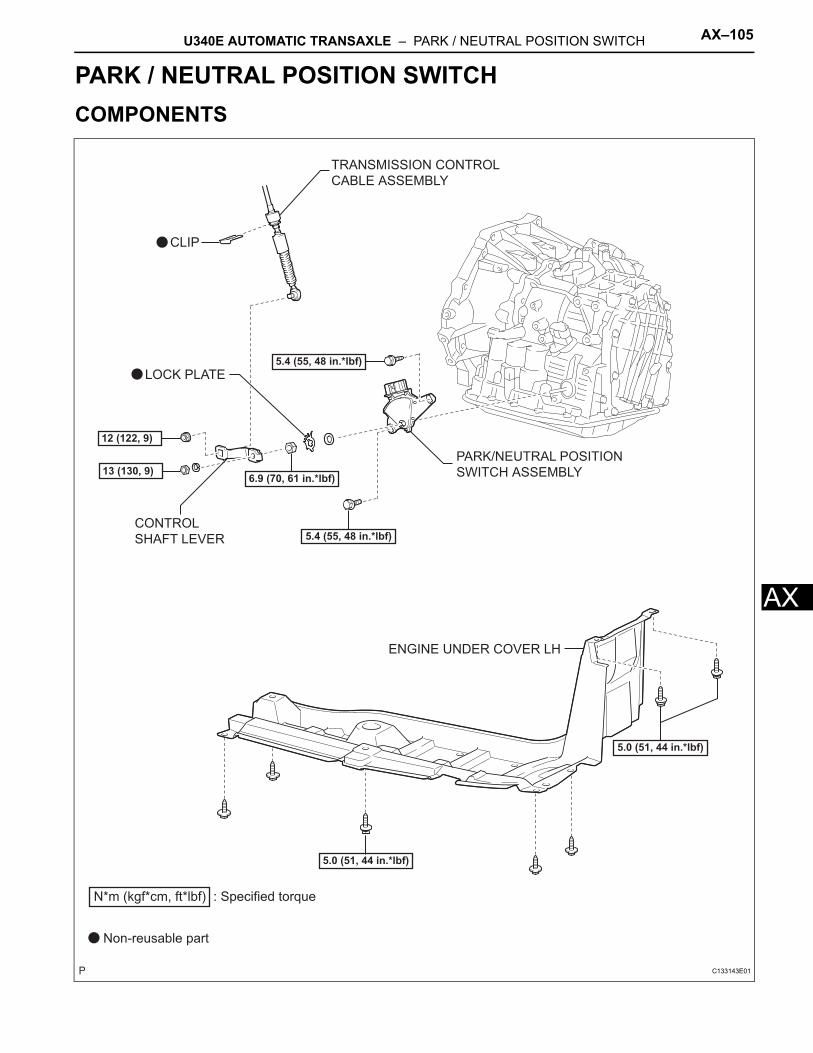
U340E AUTOMATIC TRANSAXLE – PARK / NEUTRAL POSITION SWITCH AX–105
X
ATRANSMISSIONU340E AUTOMATIC TRANSAXLEPARK / NEUTRAL POSITION SWITCHCOMPONENTS
ENGINE UNDER COVER LH
PARK/NEUTRAL POSITION
SWITCH ASSEMBLY
TRANSMISSION CONTROL
CABLE ASSEMBLY
CLIP
CONTROL
SHAFT LEVER
13 (130, 9)
12 (122, 9)
5.4 (55, 48 in.*lbf)
5.4 (55, 48 in.*lbf)
5.0 (51, 44 in.*lbf)
5.0 (51, 44 in.*lbf)
6.9 (70, 61 in.*lbf)
LOCK PLATE
N*m (kgf*cm, ft*lbf) : Specified torque
Non-reusable part
C133143E01
AX–106 U340E AUTOMATIC TRANSAXLE – PARK / NEUTRAL POSITION SWITCH
AX
ON-VEHICLE INSPECTION1. INSPECT PARK/NEUTRAL POSITION SWITCH
ASSEMBLY(a) Apply the parking brake and turn the ignition switch
ON.(b) Depress the brake pedal and check that the engine
starts when the shift lever is set in the N or P position, but does not start in the other positions.
(c) Check that the back-up light illuminates and the reverse warning buzzer sounds when the shift lever is set in the R position, but does not function in the other positions.If a malfunction failure is found, check the park/neutral position switch for continuity.
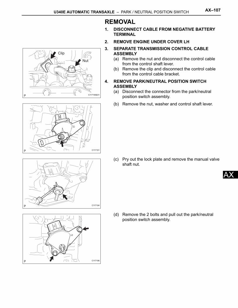
U340E AUTOMATIC TRANSAXLE – PARK / NEUTRAL POSITION SWITCH AX–107
X
AREMOVAL1. DISCONNECT CABLE FROM NEGATIVE BATTERY
TERMINAL2. REMOVE ENGINE UNDER COVER LH3. SEPARATE TRANSMISSION CONTROL CABLE
ASSEMBLY(a) Remove the nut and disconnect the control cable
from the control shaft lever.(b) Remove the clip and disconnect the control cable
from the control cable bracket.
4. REMOVE PARK/NEUTRAL POSITION SWITCH ASSEMBLY(a) Disconnect the connector from the park/neutral
position switch assembly.
(b) Remove the nut, washer and control shaft lever.
(c) Pry out the lock plate and remove the manual valve shaft nut.
(d) Remove the 2 bolts and pull out the park/neutral position switch assembly.
Clip
Nut
C117100E01
C117101
C117104
C117106
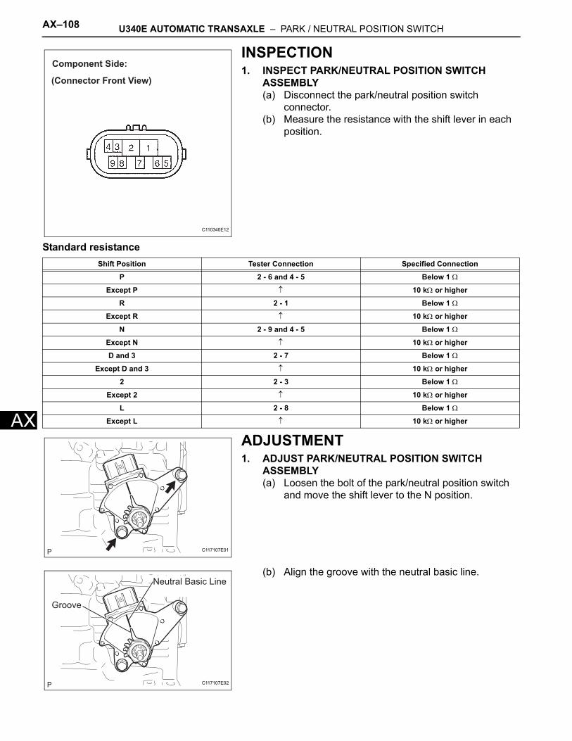
AX–108 U340E AUTOMATIC TRANSAXLE – PARK / NEUTRAL POSITION SWITCH
AX
INSPECTION1. INSPECT PARK/NEUTRAL POSITION SWITCH
ASSEMBLY(a) Disconnect the park/neutral position switch
connector.(b) Measure the resistance with the shift lever in each
position.
Standard resistance
ADJUSTMENT1. ADJUST PARK/NEUTRAL POSITION SWITCH
ASSEMBLY(a) Loosen the bolt of the park/neutral position switch
and move the shift lever to the N position.
(b) Align the groove with the neutral basic line.
Component Side:
(Connector Front View)
C110340E12
Shift Position Tester Connection Specified Connection
P 2 - 6 and 4 - 5 Below 1 Ω
Except P ↑ 10 kΩ or higher
R 2 - 1 Below 1 Ω
Except R ↑ 10 kΩ or higher
N 2 - 9 and 4 - 5 Below 1 Ω
Except N ↑ 10 kΩ or higher
D and 3 2 - 7 Below 1 Ω
Except D and 3 ↑ 10 kΩ or higher
2 2 - 3 Below 1 Ω
Except 2 ↑ 10 kΩ or higher
L 2 - 8 Below 1 Ω
Except L ↑ 10 kΩ or higher
C117107E01
Neutral Basic Line
Groove
C117107E02
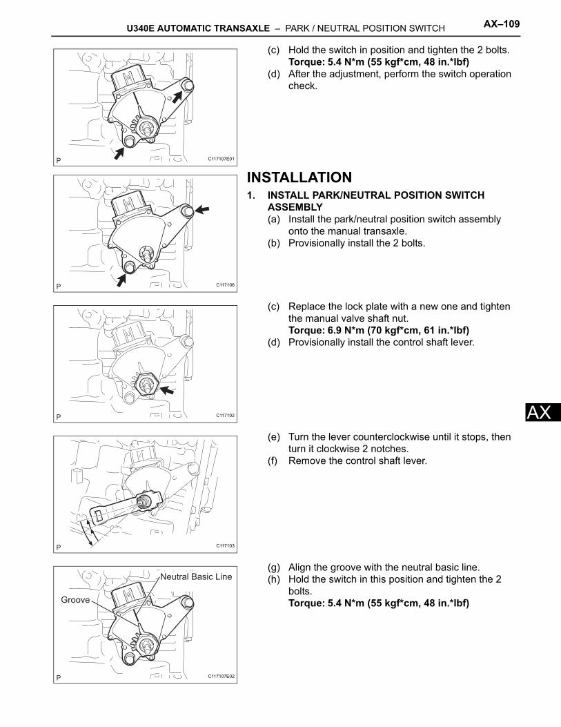
U340E AUTOMATIC TRANSAXLE – PARK / NEUTRAL POSITION SWITCH AX–109
X
A(c) Hold the switch in position and tighten the 2 bolts.Torque: 5.4 N*m (55 kgf*cm, 48 in.*lbf)
(d) After the adjustment, perform the switch operation check.
INSTALLATION1. INSTALL PARK/NEUTRAL POSITION SWITCH
ASSEMBLY(a) Install the park/neutral position switch assembly
onto the manual transaxle.(b) Provisionally install the 2 bolts.
(c) Replace the lock plate with a new one and tighten the manual valve shaft nut.Torque: 6.9 N*m (70 kgf*cm, 61 in.*lbf)
(d) Provisionally install the control shaft lever.
(e) Turn the lever counterclockwise until it stops, then turn it clockwise 2 notches.
(f) Remove the control shaft lever.
(g) Align the groove with the neutral basic line.(h) Hold the switch in this position and tighten the 2
bolts.Torque: 5.4 N*m (55 kgf*cm, 48 in.*lbf)
C117107E01
C117106
C117102
C117103
Neutral Basic Line
Groove
C117107E02
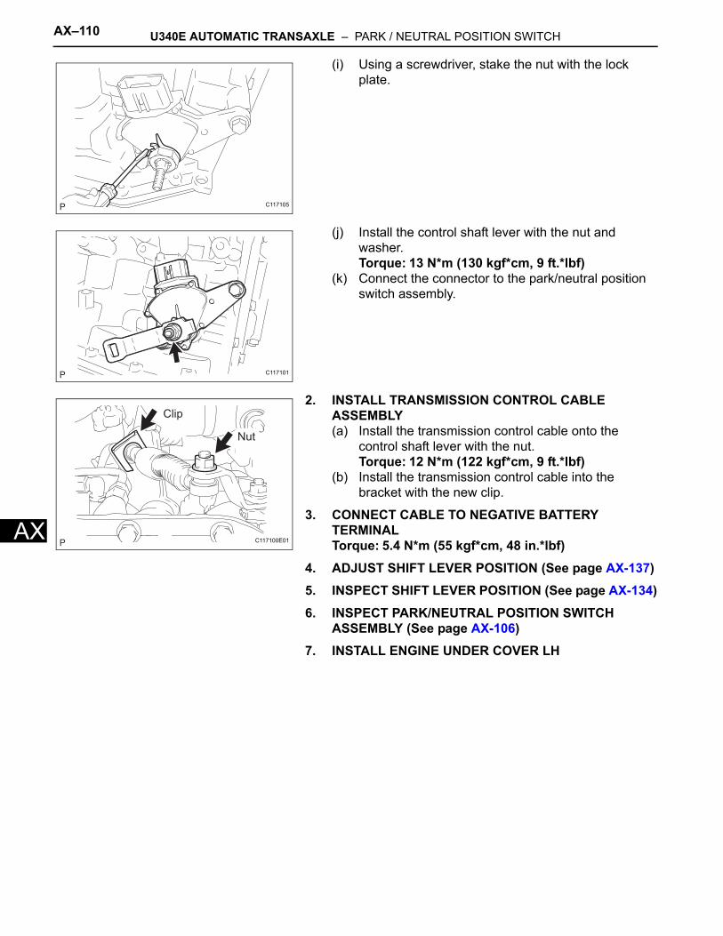
AX–110 U340E AUTOMATIC TRANSAXLE – PARK / NEUTRAL POSITION SWITCH
AX
(i) Using a screwdriver, stake the nut with the lock plate.
(j) Install the control shaft lever with the nut and washer.Torque: 13 N*m (130 kgf*cm, 9 ft.*lbf)
(k) Connect the connector to the park/neutral position switch assembly.
2. INSTALL TRANSMISSION CONTROL CABLE ASSEMBLY(a) Install the transmission control cable onto the
control shaft lever with the nut.Torque: 12 N*m (122 kgf*cm, 9 ft.*lbf)
(b) Install the transmission control cable into the bracket with the new clip.
3. CONNECT CABLE TO NEGATIVE BATTERY TERMINALTorque: 5.4 N*m (55 kgf*cm, 48 in.*lbf)
4. ADJUST SHIFT LEVER POSITION (See page AX-137)5. INSPECT SHIFT LEVER POSITION (See page AX-134)6. INSPECT PARK/NEUTRAL POSITION SWITCH
ASSEMBLY (See page AX-106)7. INSTALL ENGINE UNDER COVER LH
C117105
C117101
Clip
Nut
C117100E01
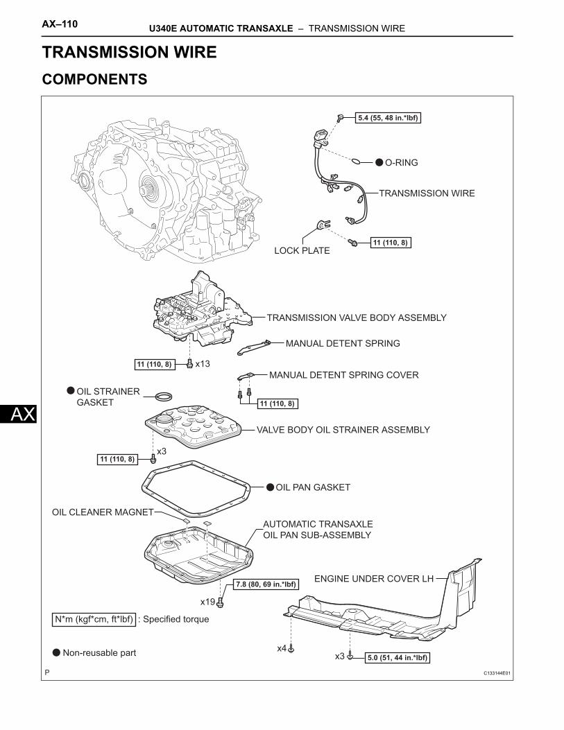
AX–110 U340E AUTOMATIC TRANSAXLE – TRANSMISSION WIRE
AX
TRANSMISSIONU340E AUTOMATIC TRANSAXLETRANSMISSION WIRECOMPONENTS
AUTOMATIC TRANSAXLE
OIL PAN SUB-ASSEMBLY
ENGINE UNDER COVER LH
TRANSMISSION VALVE BODY ASSEMBLY
TRANSMISSION WIRE
VALVE BODY OIL STRAINER ASSEMBLY
5.0 (51, 44 in.*lbf)
11 (110, 8)
x3x4
x19
7.8 (80, 69 in.*lbf)
OIL CLEANER MAGNET
OIL PAN GASKET
OIL STRAINER
GASKET
MANUAL DETENT SPRING COVER
MANUAL DETENT SPRING
O-RING
LOCK PLATE
x3
11 (110, 8)
11 (110, 8)
x13
11 (110, 8)
5.4 (55, 48 in.*lbf)
N*m (kgf*cm, ft*lbf) : Specified torque
Non-reusable part
C133144E01
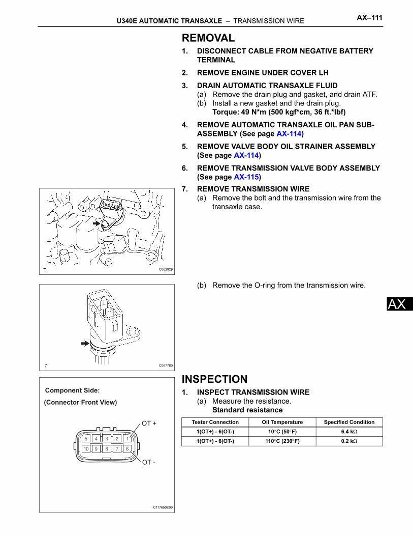
U340E AUTOMATIC TRANSAXLE – TRANSMISSION WIRE AX–111
X
AREMOVAL1. DISCONNECT CABLE FROM NEGATIVE BATTERY
TERMINAL2. REMOVE ENGINE UNDER COVER LH3. DRAIN AUTOMATIC TRANSAXLE FLUID
(a) Remove the drain plug and gasket, and drain ATF.(b) Install a new gasket and the drain plug.
Torque: 49 N*m (500 kgf*cm, 36 ft.*lbf)4. REMOVE AUTOMATIC TRANSAXLE OIL PAN SUB-
ASSEMBLY (See page AX-114)5. REMOVE VALVE BODY OIL STRAINER ASSEMBLY
(See page AX-114)6. REMOVE TRANSMISSION VALVE BODY ASSEMBLY
(See page AX-115)7. REMOVE TRANSMISSION WIRE
(a) Remove the bolt and the transmission wire from the transaxle case.
(b) Remove the O-ring from the transmission wire.
INSPECTION1. INSPECT TRANSMISSION WIRE
(a) Measure the resistance.Standard resistance
C062929
C067760
(Connector Front View)
Component Side:
OT +
OT -
C117650E09
Tester Connection Oil Temperature Specified Condition
1(OT+) - 6(OT-) 10°C (50°F) 6.4 kΩ
1(OT+) - 6(OT-) 110°C (230°F) 0.2 kΩ
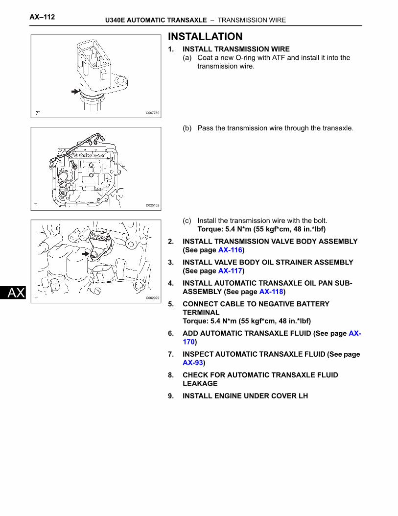
AX–112 U340E AUTOMATIC TRANSAXLE – TRANSMISSION WIRE
AX
INSTALLATION1. INSTALL TRANSMISSION WIRE
(a) Coat a new O-ring with ATF and install it into the transmission wire.
(b) Pass the transmission wire through the transaxle.
(c) Install the transmission wire with the bolt.Torque: 5.4 N*m (55 kgf*cm, 48 in.*lbf)
2. INSTALL TRANSMISSION VALVE BODY ASSEMBLY (See page AX-116)
3. INSTALL VALVE BODY OIL STRAINER ASSEMBLY (See page AX-117)
4. INSTALL AUTOMATIC TRANSAXLE OIL PAN SUB-ASSEMBLY (See page AX-118)
5. CONNECT CABLE TO NEGATIVE BATTERY TERMINALTorque: 5.4 N*m (55 kgf*cm, 48 in.*lbf)
6. ADD AUTOMATIC TRANSAXLE FLUID (See page AX-170)
7. INSPECT AUTOMATIC TRANSAXLE FLUID (See page AX-93)
8. CHECK FOR AUTOMATIC TRANSAXLE FLUID LEAKAGE
9. INSTALL ENGINE UNDER COVER LH
C067760
D025102
C062929
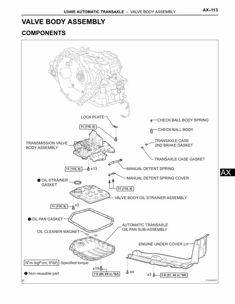
U340E AUTOMATIC TRANSAXLE – VALVE BODY ASSEMBLY AX–113
X
ATRANSMISSIONU340E AUTOMATIC TRANSAXLEVALVE BODY ASSEMBLYCOMPONENTS
ENGINE UNDER COVER LH
TRANSMISSION VALVE
BODY ASSEMBLY
VALVE BODY OIL STRAINER ASSEMBLY
AUTOMATIC TRANSAXLE
OIL PAN SUB-ASSEMBLY
OIL PAN GASKET
OIL CLEANER MAGNET
OIL STRAINER
GASKET
N*m (kgf*cm, ft*lbf) :Specified torque
5.0 (51, 44 in.*lbf)Non-reusable part
x19
MANUAL DETENT SPRING COVER
MANUAL DETENT SPRING
CHECK BALL BODY SPRING
CHECK BALL BODY
11 (110, 8)
TRANSAXLE CASE
2ND BRAKE GASKET
TRANSAXLE CASE GASKET
LOCK PLATE
x3x4
x3
7.8 (80, 69 in.*lbf)
11 (110, 8)
11 (110, 8)
x13
11 (110, 8)
C121641E01
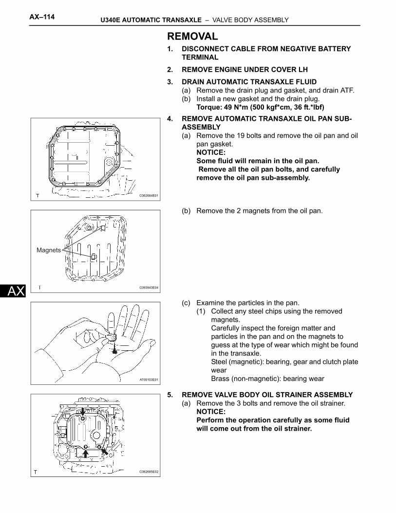
AX–114 U340E AUTOMATIC TRANSAXLE – VALVE BODY ASSEMBLY
AX
REMOVAL1. DISCONNECT CABLE FROM NEGATIVE BATTERY
TERMINAL2. REMOVE ENGINE UNDER COVER LH3. DRAIN AUTOMATIC TRANSAXLE FLUID
(a) Remove the drain plug and gasket, and drain ATF.(b) Install a new gasket and the drain plug.
Torque: 49 N*m (500 kgf*cm, 36 ft.*lbf)4. REMOVE AUTOMATIC TRANSAXLE OIL PAN SUB-
ASSEMBLY(a) Remove the 19 bolts and remove the oil pan and oil
pan gasket.NOTICE:Some fluid will remain in the oil pan. Remove all the oil pan bolts, and carefully remove the oil pan sub-assembly.
(b) Remove the 2 magnets from the oil pan.
(c) Examine the particles in the pan.(1) Collect any steel chips using the removed
magnets.Carefully inspect the foreign matter and particles in the pan and on the magnets to guess at the type of wear which might be found in the transaxle.Steel (magnetic): bearing, gear and clutch plate wearBrass (non-magnetic): bearing wear
5. REMOVE VALVE BODY OIL STRAINER ASSEMBLY(a) Remove the 3 bolts and remove the oil strainer.
NOTICE:Perform the operation carefully as some fluid will come out from the oil strainer.
C062684E01
Magnets
C093943E04
AT00103E01
C062685E02
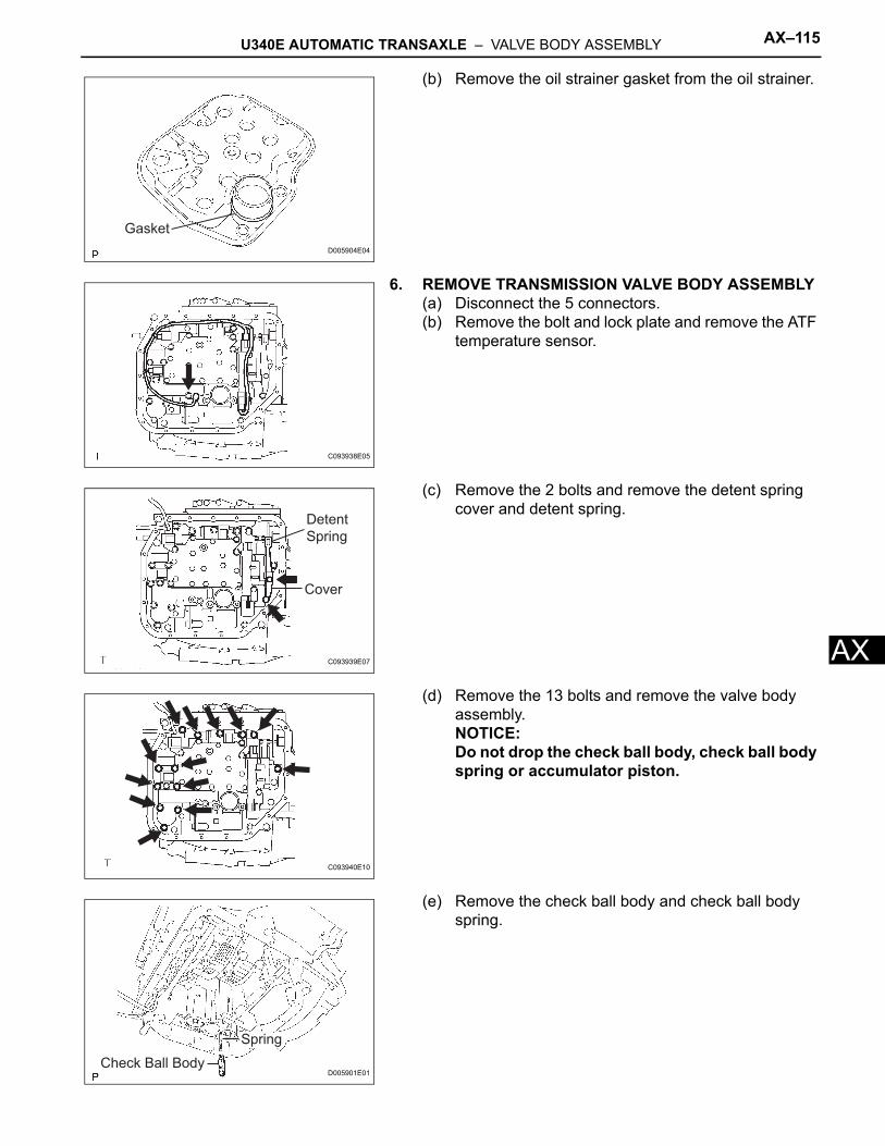
U340E AUTOMATIC TRANSAXLE – VALVE BODY ASSEMBLY AX–115
X
A(b) Remove the oil strainer gasket from the oil strainer.
6. REMOVE TRANSMISSION VALVE BODY ASSEMBLY(a) Disconnect the 5 connectors.(b) Remove the bolt and lock plate and remove the ATF
temperature sensor.
(c) Remove the 2 bolts and remove the detent spring cover and detent spring.
(d) Remove the 13 bolts and remove the valve body assembly.NOTICE:Do not drop the check ball body, check ball body spring or accumulator piston.
(e) Remove the check ball body and check ball body spring.
Gasket
D005904E04
C093938E05
Detent
Spring
Cover
C093939E07
C093940E10
Spring
Check Ball BodyD005901E01
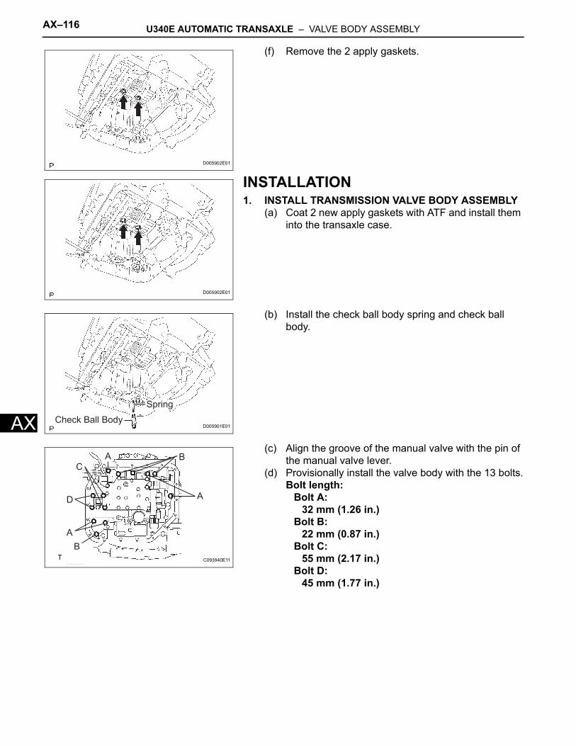
AX–116 U340E AUTOMATIC TRANSAXLE – VALVE BODY ASSEMBLY
AX
(f) Remove the 2 apply gaskets.
INSTALLATION1. INSTALL TRANSMISSION VALVE BODY ASSEMBLY
(a) Coat 2 new apply gaskets with ATF and install them into the transaxle case.
(b) Install the check ball body spring and check ball body.
(c) Align the groove of the manual valve with the pin of the manual valve lever.
(d) Provisionally install the valve body with the 13 bolts.Bolt length:
Bolt A:32 mm (1.26 in.)
Bolt B:22 mm (0.87 in.)
Bolt C:55 mm (2.17 in.)
Bolt D:45 mm (1.77 in.)
D005902E01
D005902E01
Spring
Check Ball BodyD005901E01
B
A
D
CA B
A
C093940E11
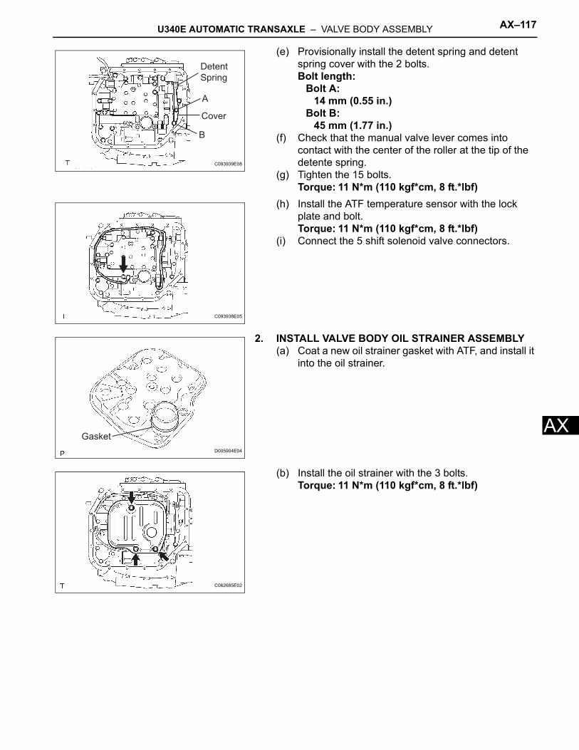
U340E AUTOMATIC TRANSAXLE – VALVE BODY ASSEMBLY AX–117
X
A(e) Provisionally install the detent spring and detent spring cover with the 2 bolts.Bolt length:
Bolt A:14 mm (0.55 in.)
Bolt B:45 mm (1.77 in.)
(f) Check that the manual valve lever comes into contact with the center of the roller at the tip of the detente spring.
(g) Tighten the 15 bolts.Torque: 11 N*m (110 kgf*cm, 8 ft.*lbf)
(h) Install the ATF temperature sensor with the lock plate and bolt.Torque: 11 N*m (110 kgf*cm, 8 ft.*lbf)
(i) Connect the 5 shift solenoid valve connectors.
2. INSTALL VALVE BODY OIL STRAINER ASSEMBLY(a) Coat a new oil strainer gasket with ATF, and install it
into the oil strainer.
(b) Install the oil strainer with the 3 bolts.Torque: 11 N*m (110 kgf*cm, 8 ft.*lbf)
Detent
Spring
A
Cover
B
C093939E08
C093938E05
Gasket
D005904E04
C062685E02
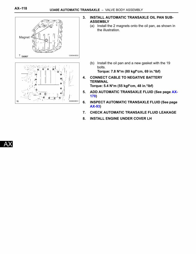
AX–118 U340E AUTOMATIC TRANSAXLE – VALVE BODY ASSEMBLY
AX
3. INSTALL AUTOMATIC TRANSAXLE OIL PAN SUB-ASSEMBLY(a) Install the 2 magnets onto the oil pan, as shown in
the illustration.
(b) Install the oil pan and a new gasket with the 19 bolts.Torque: 7.8 N*m (80 kgf*cm, 69 in.*lbf)
4. CONNECT CABLE TO NEGATIVE BATTERY TERMINALTorque: 5.4 N*m (55 kgf*cm, 48 in.*lbf)
5. ADD AUTOMATIC TRANSAXLE FLUID (See page AX-170)
6. INSPECT AUTOMATIC TRANSAXLE FLUID (See page AX-93)
7. CHECK AUTOMATIC TRANSAXLE FLUID LEAKAGE8. INSTALL ENGINE UNDER COVER LH
Magnet
C093943E02
D008009E01
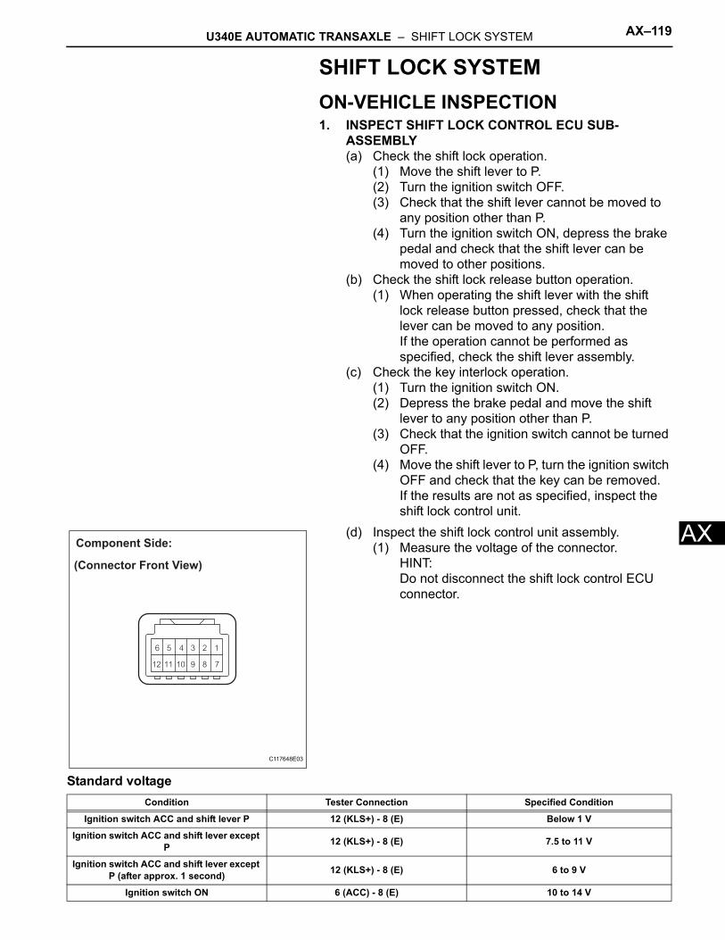
U340E AUTOMATIC TRANSAXLE – SHIFT LOCK SYSTEM AX–119
X
ASHIFT LOCK SYSTEMON-VEHICLE INSPECTION1. INSPECT SHIFT LOCK CONTROL ECU SUB-
ASSEMBLY(a) Check the shift lock operation.
(1) Move the shift lever to P.(2) Turn the ignition switch OFF.(3) Check that the shift lever cannot be moved to
any position other than P.(4) Turn the ignition switch ON, depress the brake
pedal and check that the shift lever can be moved to other positions.
(b) Check the shift lock release button operation.(1) When operating the shift lever with the shift
lock release button pressed, check that the lever can be moved to any position.If the operation cannot be performed as specified, check the shift lever assembly.
(c) Check the key interlock operation.(1) Turn the ignition switch ON.(2) Depress the brake pedal and move the shift
lever to any position other than P.(3) Check that the ignition switch cannot be turned
OFF.(4) Move the shift lever to P, turn the ignition switch
OFF and check that the key can be removed.If the results are not as specified, inspect the shift lock control unit.
(d) Inspect the shift lock control unit assembly.(1) Measure the voltage of the connector.
HINT:Do not disconnect the shift lock control ECU connector.
Standard voltage
(Connector Front View)
Component Side:
C117648E03
Condition Tester Connection Specified Condition
Ignition switch ACC and shift lever P 12 (KLS+) - 8 (E) Below 1 V
Ignition switch ACC and shift lever except P 12 (KLS+) - 8 (E) 7.5 to 11 V
Ignition switch ACC and shift lever except P (after approx. 1 second) 12 (KLS+) - 8 (E) 6 to 9 V
Ignition switch ON 6 (ACC) - 8 (E) 10 to 14 V
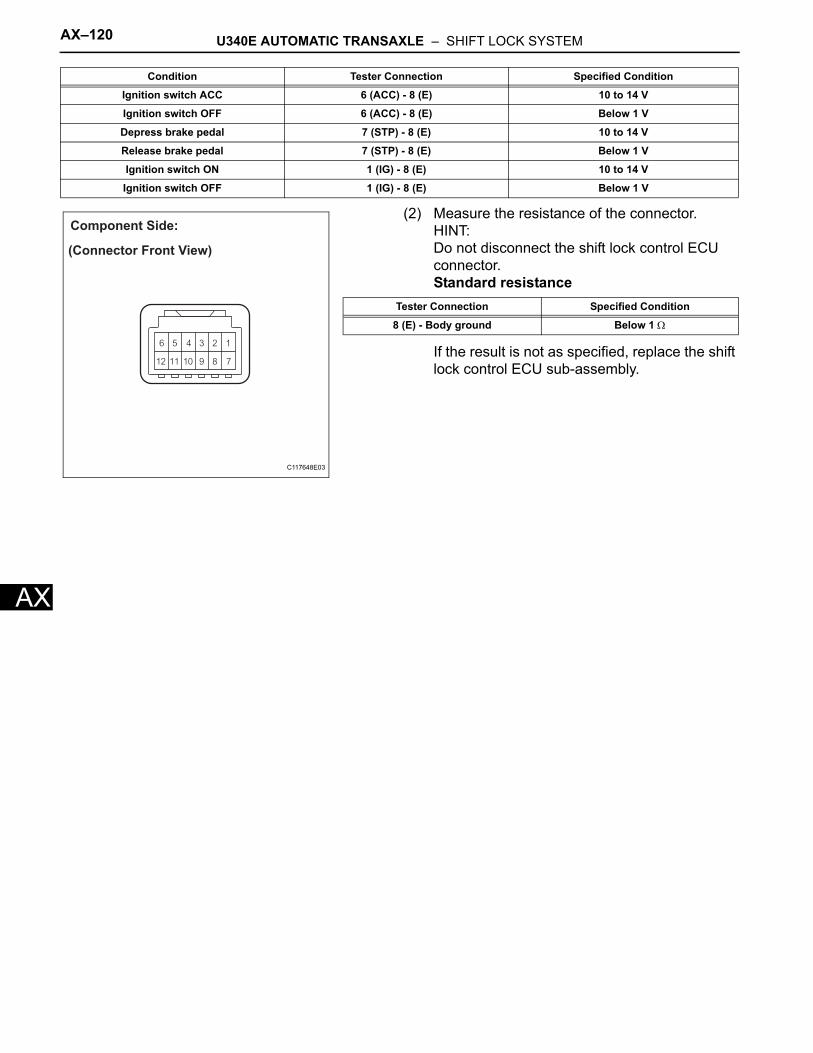
AX–120 U340E AUTOMATIC TRANSAXLE – SHIFT LOCK SYSTEM
AX
(2) Measure the resistance of the connector.HINT:Do not disconnect the shift lock control ECU connector.Standard resistance
If the result is not as specified, replace the shift lock control ECU sub-assembly.
Ignition switch ACC 6 (ACC) - 8 (E) 10 to 14 V
Ignition switch OFF 6 (ACC) - 8 (E) Below 1 V
Depress brake pedal 7 (STP) - 8 (E) 10 to 14 V
Release brake pedal 7 (STP) - 8 (E) Below 1 V
Ignition switch ON 1 (IG) - 8 (E) 10 to 14 V
Ignition switch OFF 1 (IG) - 8 (E) Below 1 V
Condition Tester Connection Specified Condition
(Connector Front View)
Component Side:
C117648E03
Tester Connection Specified Condition
8 (E) - Body ground Below 1 Ω
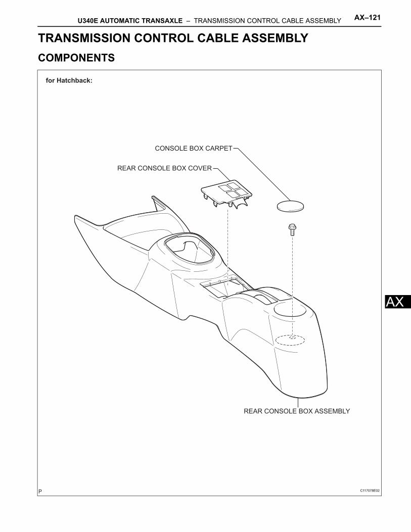
U340E AUTOMATIC TRANSAXLE – TRANSMISSION CONTROL CABLE ASSEMBLY AX–121
X
ATRANSMISSIONU340E AUTOMATIC TRANSAXLETRANSMISSION CONTROL CABLE ASSEMBLYCOMPONENTS
for Hatchback:
CONSOLE BOX CARPET
REAR CONSOLE BOX ASSEMBLY
REAR CONSOLE BOX COVER
C117078E02
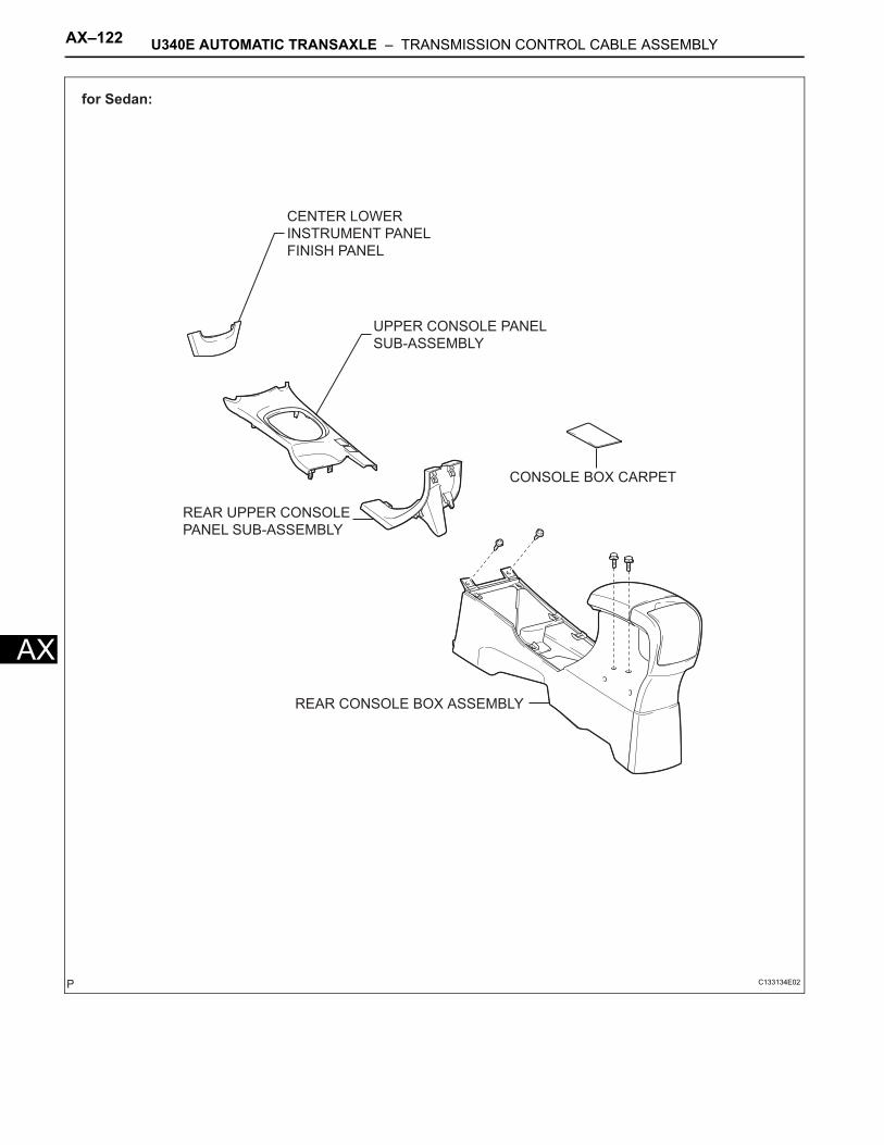
AX–122 U340E AUTOMATIC TRANSAXLE – TRANSMISSION CONTROL CABLE ASSEMBLY
AX
for Sedan:
CENTER LOWER
INSTRUMENT PANEL
FINISH PANEL
CONSOLE BOX CARPET
REAR CONSOLE BOX ASSEMBLY
REAR UPPER CONSOLE
PANEL SUB-ASSEMBLY
UPPER CONSOLE PANEL
SUB-ASSEMBLY
C133134E02
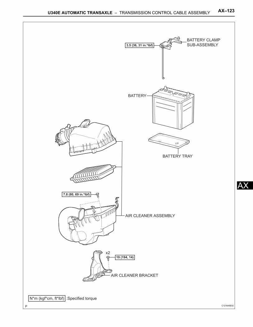
U340E AUTOMATIC TRANSAXLE – TRANSMISSION CONTROL CABLE ASSEMBLY AX–123
X
AAIR CLEANER ASSEMBLY
AIR CLEANER BRACKET
BATTERY TRAY
N*m (kgf*cm, ft*lbf) :Specified torque
19 (194, 14)x2
7.8 (80, 69 in.*lbf)
3.5 (36, 31 in.*lbf)
BATTERY
BATTERY CLAMP
SUB-ASSEMBLY
C121645E02
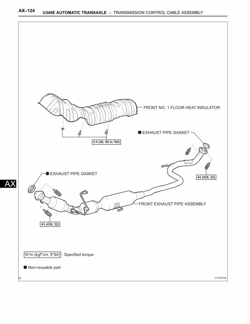
AX–124 U340E AUTOMATIC TRANSAXLE – TRANSMISSION CONTROL CABLE ASSEMBLY
AX
5.5 (56, 49 in.*lbf)
43 (439, 32)
43 (439, 32)EXHAUST PIPE GASKET
EXHAUST PIPE GASKET
N*m (kgf*cm, ft*lbf) : Specified torque
Non-reusable part
FRONT EXHAUST PIPE ASSEMBLY
FRONT NO. 1 FLOOR HEAT INSULATOR
C117081E02
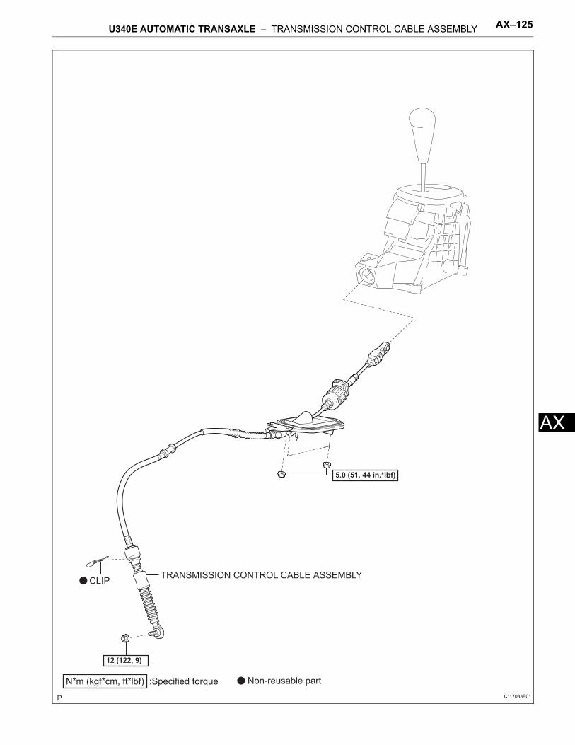
U340E AUTOMATIC TRANSAXLE – TRANSMISSION CONTROL CABLE ASSEMBLY AX–125
X
ATRANSMISSION CONTROL CABLE ASSEMBLY
N*m (kgf*cm, ft*lbf) :Specified torque
5.0 (51, 44 in.*lbf)
Non-reusable part
12 (122, 9)
CLIP
C117083E01
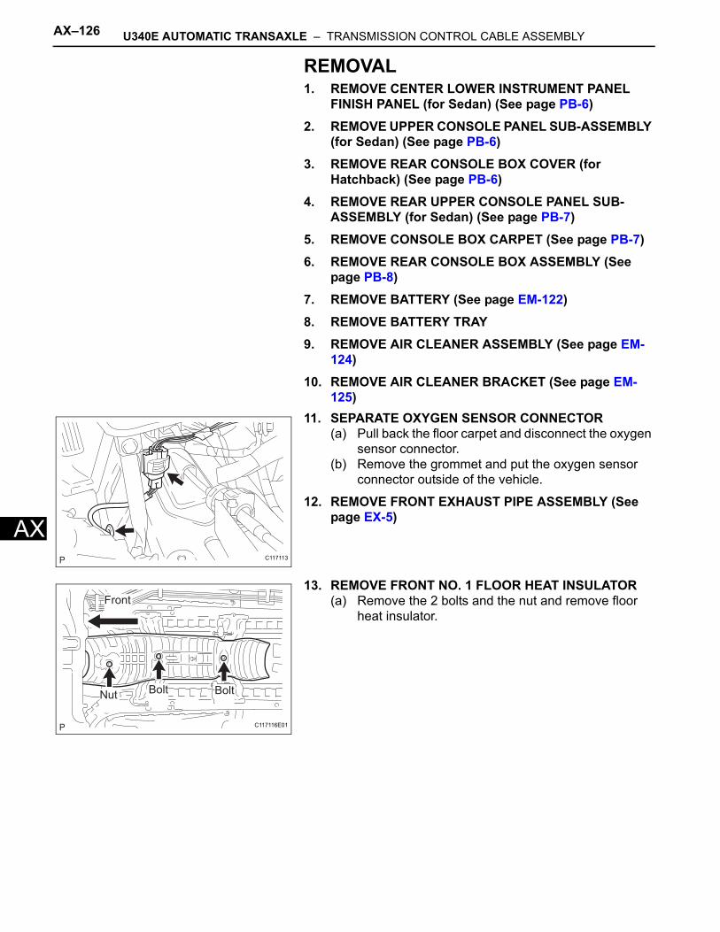
AX–126 U340E AUTOMATIC TRANSAXLE – TRANSMISSION CONTROL CABLE ASSEMBLY
AX
REMOVAL1. REMOVE CENTER LOWER INSTRUMENT PANEL
FINISH PANEL (for Sedan) (See page PB-6)2. REMOVE UPPER CONSOLE PANEL SUB-ASSEMBLY
(for Sedan) (See page PB-6)3. REMOVE REAR CONSOLE BOX COVER (for
Hatchback) (See page PB-6)4. REMOVE REAR UPPER CONSOLE PANEL SUB-
ASSEMBLY (for Sedan) (See page PB-7)5. REMOVE CONSOLE BOX CARPET (See page PB-7)6. REMOVE REAR CONSOLE BOX ASSEMBLY (See
page PB-8)7. REMOVE BATTERY (See page EM-122)8. REMOVE BATTERY TRAY9. REMOVE AIR CLEANER ASSEMBLY (See page EM-
124)10. REMOVE AIR CLEANER BRACKET (See page EM-
125)11. SEPARATE OXYGEN SENSOR CONNECTOR
(a) Pull back the floor carpet and disconnect the oxygen sensor connector.
(b) Remove the grommet and put the oxygen sensor connector outside of the vehicle.
12. REMOVE FRONT EXHAUST PIPE ASSEMBLY (See page EX-5)
13. REMOVE FRONT NO. 1 FLOOR HEAT INSULATOR(a) Remove the 2 bolts and the nut and remove floor
heat insulator.
C117113
Bolt BoltNut
Front
C117116E01
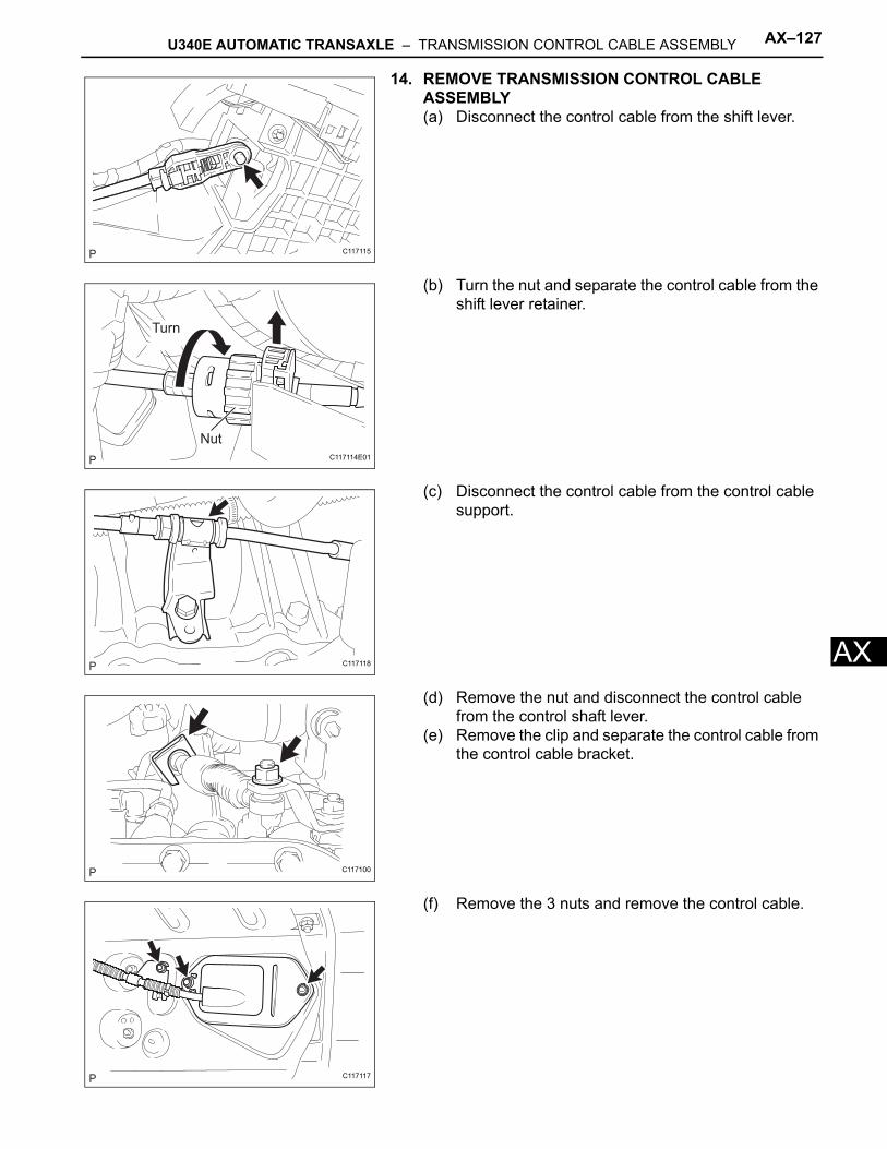
U340E AUTOMATIC TRANSAXLE – TRANSMISSION CONTROL CABLE ASSEMBLY AX–127
X
A14. REMOVE TRANSMISSION CONTROL CABLE ASSEMBLY(a) Disconnect the control cable from the shift lever.
(b) Turn the nut and separate the control cable from the shift lever retainer.
(c) Disconnect the control cable from the control cable support.
(d) Remove the nut and disconnect the control cable from the control shaft lever.
(e) Remove the clip and separate the control cable from the control cable bracket.
(f) Remove the 3 nuts and remove the control cable.
C117115
Nut
Turn
C117114E01
C117118
C117100
C117117
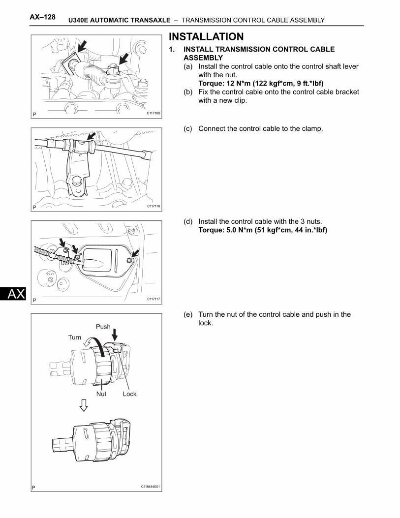
AX–128 U340E AUTOMATIC TRANSAXLE – TRANSMISSION CONTROL CABLE ASSEMBLY
AX
INSTALLATION1. INSTALL TRANSMISSION CONTROL CABLE
ASSEMBLY(a) Install the control cable onto the control shaft lever
with the nut.Torque: 12 N*m (122 kgf*cm, 9 ft.*lbf)
(b) Fix the control cable onto the control cable bracket with a new clip.
(c) Connect the control cable to the clamp.
(d) Install the control cable with the 3 nuts.Torque: 5.0 N*m (51 kgf*cm, 44 in.*lbf)
(e) Turn the nut of the control cable and push in the lock.
C117100
C117118
C117117
Push
Turn
Nut Lock
C118484E01
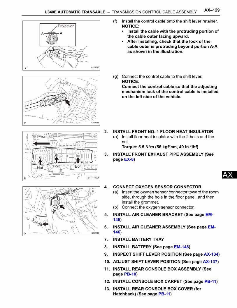
U340E AUTOMATIC TRANSAXLE – TRANSMISSION CONTROL CABLE ASSEMBLY AX–129
X
A(f) Install the control cable onto the shift lever retainer.NOTICE:• Install the cable with the protruding portion of
the cable outer facing upward.• After installing, check that the lock of the
cable outer is protruding beyond portion A-A, as shown in the illustration.
(g) Connect the control cable to the shift lever.NOTICE:Connect the control cable so that the adjusting mechanism lock of the control cable is installed on the left side of the vehicle.
2. INSTALL FRONT NO. 1 FLOOR HEAT INSULATOR(a) Install floor heat insulator with the 2 bolts and the
nut.Torque: 5.5 N*m (56 kgf*cm, 49 in.*lbf)
3. INSTALL FRONT EXHAUST PIPE ASSEMBLY (See page EX-8)
4. CONNECT OXYGEN SENSOR CONNECTOR(a) Insert the oxygen sensor connector toward the room
side, through the hole in the floor panel, and then install the grommet.
(b) Connect the oxygen sensor connector.
5. INSTALL AIR CLEANER BRACKET (See page EM-145)
6. INSTALL AIR CLEANER ASSEMBLY (See page EM-146)
7. INSTALL BATTERY TRAY8. INSTALL BATTERY (See page EM-148)9. INSPECT SHIFT LEVER POSITION (See page AX-134)10. ADJUST SHIFT LEVER POSITION (See page AX-137)11. INSTALL REAR CONSOLE BOX ASSEMBLY (See
page PB-10)12. INSTALL CONSOLE BOX CARPET (See page PB-11)13. INSTALL REAR CONSOLE BOX COVER (for
Hatchback) (See page PB-11)
A A
Projection
C121646
C117115
Bolt BoltNut
Front
C117116E01
C117113
AX–130 U340E AUTOMATIC TRANSAXLE – TRANSMISSION CONTROL CABLE ASSEMBLY
AX
14. INSTALL REAR UPPER CONSOLE PANEL SUB-ASSEMBLY (for Sedan) (See page PB-11)
15. INSTALL UPPER CONSOLE PANEL SUB-ASSEMBLY (for Sedan) (See page PB-12)
16. INSTALL CENTER LOWER INSTRUMENT PANEL FINISH PANEL (for Sedan) (See page PB-12)
17. CHECK FOR EXHAUST GAS LEAKAGE
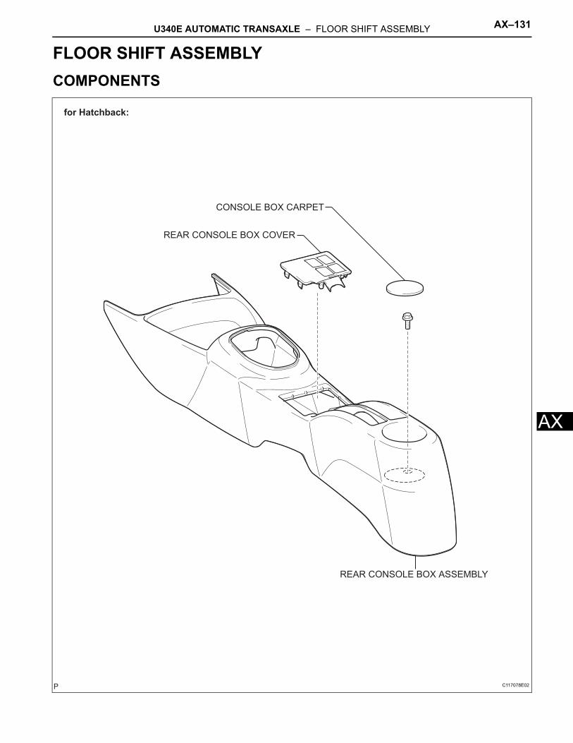
U340E AUTOMATIC TRANSAXLE – FLOOR SHIFT ASSEMBLY AX–131
X
ATRANSMISSIONU340E AUTOMATIC TRANSAXLEFLOOR SHIFT ASSEMBLYCOMPONENTS
for Hatchback:
CONSOLE BOX CARPET
REAR CONSOLE BOX ASSEMBLY
REAR CONSOLE BOX COVER
C117078E02
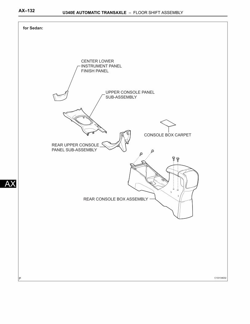
AX–132 U340E AUTOMATIC TRANSAXLE – FLOOR SHIFT ASSEMBLY
AX
for Sedan:
CENTER LOWER
INSTRUMENT PANEL
FINISH PANEL
CONSOLE BOX CARPET
REAR CONSOLE BOX ASSEMBLY
REAR UPPER CONSOLE
PANEL SUB-ASSEMBLY
UPPER CONSOLE PANEL
SUB-ASSEMBLY
C133134E02
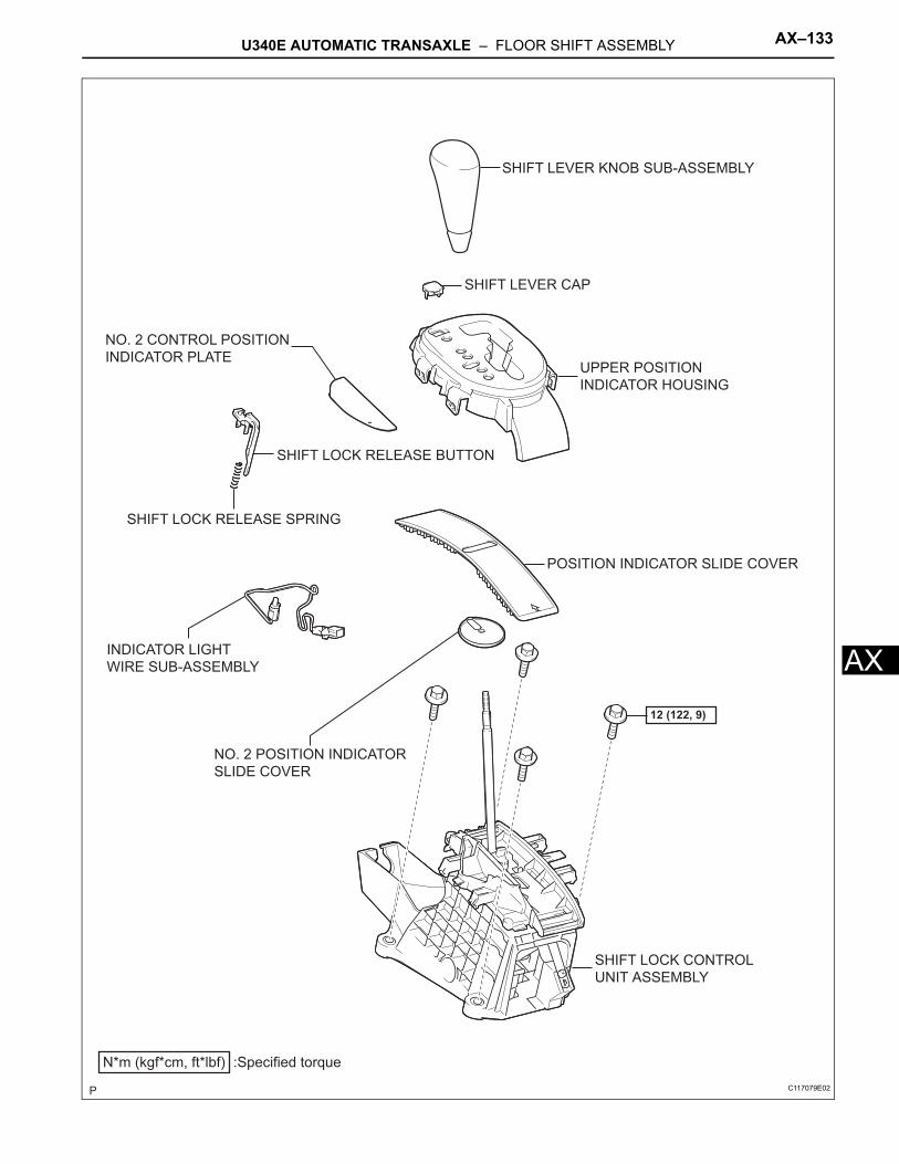
U340E AUTOMATIC TRANSAXLE – FLOOR SHIFT ASSEMBLY AX–133
X
AINDICATOR LIGHTWIRE SUB-ASSEMBLY
SHIFT LOCK RELEASE BUTTON
SHIFT LEVER KNOB SUB-ASSEMBLY
SHIFT LOCK RELEASE SPRING
N*m (kgf*cm, ft*lbf) :Specified torque
12 (122, 9)
SHIFT LOCK CONTROL
UNIT ASSEMBLY
NO. 2 CONTROL POSITION
INDICATOR PLATEUPPER POSITION
INDICATOR HOUSING
SHIFT LEVER CAP
NO. 2 POSITION INDICATOR
SLIDE COVER
POSITION INDICATOR SLIDE COVER
C117079E02
AX–134 U340E AUTOMATIC TRANSAXLE – FLOOR SHIFT ASSEMBLY
AX
ON-VEHICLE INSPECTION1. INSPECT SHIFT LEVER POSITION
(a) When shifting the lever from P to the R position with the ignition switch ON and the brake pedal depressed, make sure that the shift lever moves smoothly and moves correctly into position.
(b) Start the engine and make sure that the vehicle moves forward when shifting the lever from N to the D position and moves rearward when shifting the lever to the R position.If the operation cannot be performed as specified, inspect the park/neutral position switch assembly and check the shift lever assembly installation condition.
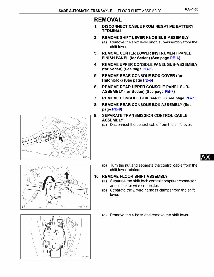
U340E AUTOMATIC TRANSAXLE – FLOOR SHIFT ASSEMBLY AX–135
X
AREMOVAL1. DISCONNECT CABLE FROM NEGATIVE BATTERY
TERMINAL2. REMOVE SHIFT LEVER KNOB SUB-ASSEMBLY
(a) Remove the shift lever knob sub-assembly from the shift lever.
3. REMOVE CENTER LOWER INSTRUMENT PANEL FINISH PANEL (for Sedan) (See page PB-6)
4. REMOVE UPPER CONSOLE PANEL SUB-ASSEMBLY (for Sedan) (See page PB-6)
5. REMOVE REAR CONSOLE BOX COVER (for Hatchback) (See page PB-6)
6. REMOVE REAR UPPER CONSOLE PANEL SUB-ASSEMBLY (for Sedan) (See page PB-7)
7. REMOVE CONSOLE BOX CARPET (See page PB-7)8. REMOVE REAR CONSOLE BOX ASSEMBLY (See
page PB-8)9. SEPARATE TRANSMISSION CONTROL CABLE
ASSEMBLY(a) Disconnect the control cable from the shift lever.
(b) Turn the nut and separate the control cable from the shift lever retainer.
10. REMOVE FLOOR SHIFT ASSEMBLY(a) Separate the shift lock control computer connector
and indicator wire connector.(b) Separate the 2 wire harness clamps from the shift
lever.
(c) Remove the 4 bolts and remove the shift lever.
C117115
Nut
Turn
C117114E01
C118483

AX–136 U340E AUTOMATIC TRANSAXLE – FLOOR SHIFT ASSEMBLY
AX
DISASSEMBLY1. REMOVE SHIFT LEVER CAP
(a) Remove the shift lever cap from the position indicator housing upper.
2. REMOVE UPPER POSITION INDICATOR HOUSING(a) Release the 4 claws using a screwdriver and
remove the upper position indicator housing from the shift lock control unit.
3. REMOVE NO. 2 CONTROL POSITION INDICATOR PLATE(a) Release the 2 claws using a screwdriver and
remove position indicator plate from the upper position indicator housing.
4. REMOVE POSITION INDICATOR SLIDE COVER(a) Remove the position indicator slide cover from the
shift lock control unit.
C118485
C118486
C118487E01
C118488
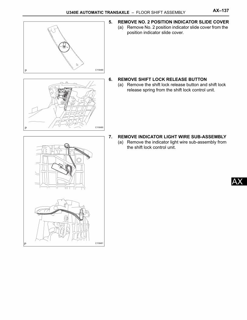
U340E AUTOMATIC TRANSAXLE – FLOOR SHIFT ASSEMBLY AX–137
X
A5. REMOVE NO. 2 POSITION INDICATOR SLIDE COVER(a) Remove No. 2 position indicator slide cover from the
position indicator slide cover.
6. REMOVE SHIFT LOCK RELEASE BUTTON(a) Remove the shift lock release button and shift lock
release spring from the shift lock control unit.
7. REMOVE INDICATOR LIGHT WIRE SUB-ASSEMBLY(a) Remove the indicator light wire sub-assembly from
the shift lock control unit.
C118489
C118490
C118491
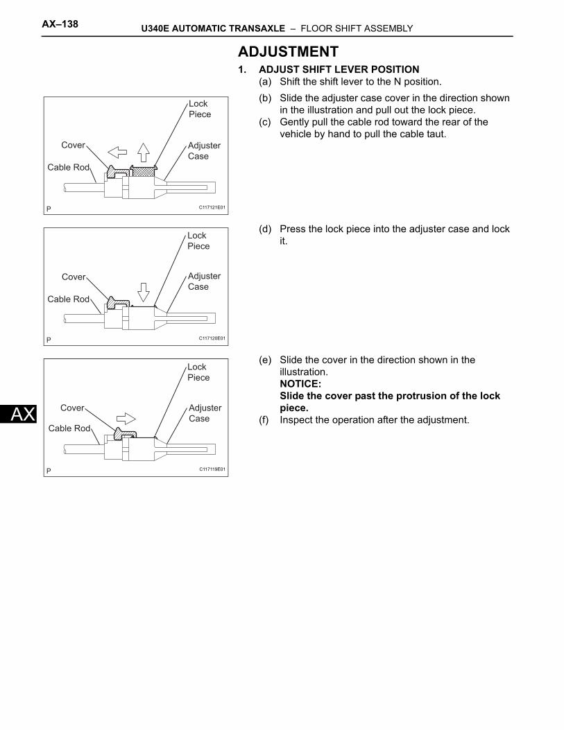
AX–138 U340E AUTOMATIC TRANSAXLE – FLOOR SHIFT ASSEMBLY
AX
ADJUSTMENT1. ADJUST SHIFT LEVER POSITION
(a) Shift the shift lever to the N position.(b) Slide the adjuster case cover in the direction shown
in the illustration and pull out the lock piece.(c) Gently pull the cable rod toward the rear of the
vehicle by hand to pull the cable taut.
(d) Press the lock piece into the adjuster case and lock it.
(e) Slide the cover in the direction shown in the illustration.NOTICE:Slide the cover past the protrusion of the lock piece.
(f) Inspect the operation after the adjustment.
Cable Rod
Cover Adjuster
Case
Lock
Piece
C117121E01
Cable Rod
Cover Adjuster
Case
Lock
Piece
C117120E01
Cable Rod
Cover Adjuster
Case
Lock
Piece
C117119E01
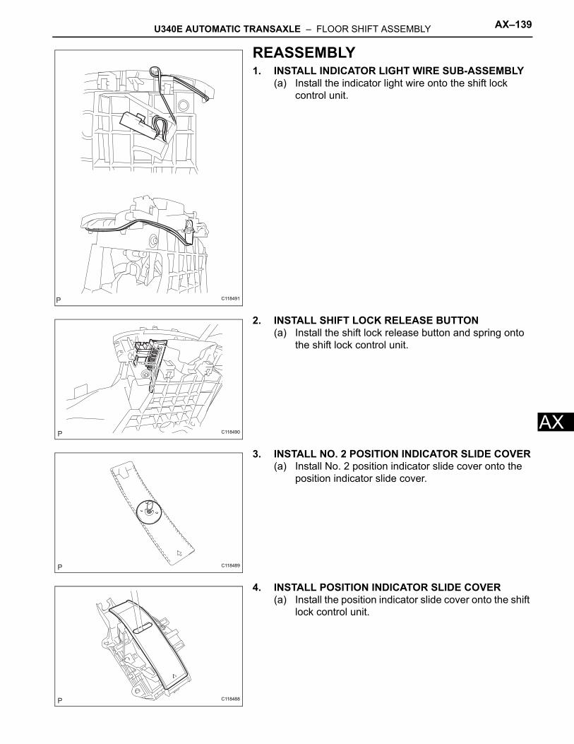
U340E AUTOMATIC TRANSAXLE – FLOOR SHIFT ASSEMBLY AX–139
X
AREASSEMBLY1. INSTALL INDICATOR LIGHT WIRE SUB-ASSEMBLY
(a) Install the indicator light wire onto the shift lock control unit.
2. INSTALL SHIFT LOCK RELEASE BUTTON(a) Install the shift lock release button and spring onto
the shift lock control unit.
3. INSTALL NO. 2 POSITION INDICATOR SLIDE COVER(a) Install No. 2 position indicator slide cover onto the
position indicator slide cover.
4. INSTALL POSITION INDICATOR SLIDE COVER(a) Install the position indicator slide cover onto the shift
lock control unit.
C118491
C118490
C118489
C118488
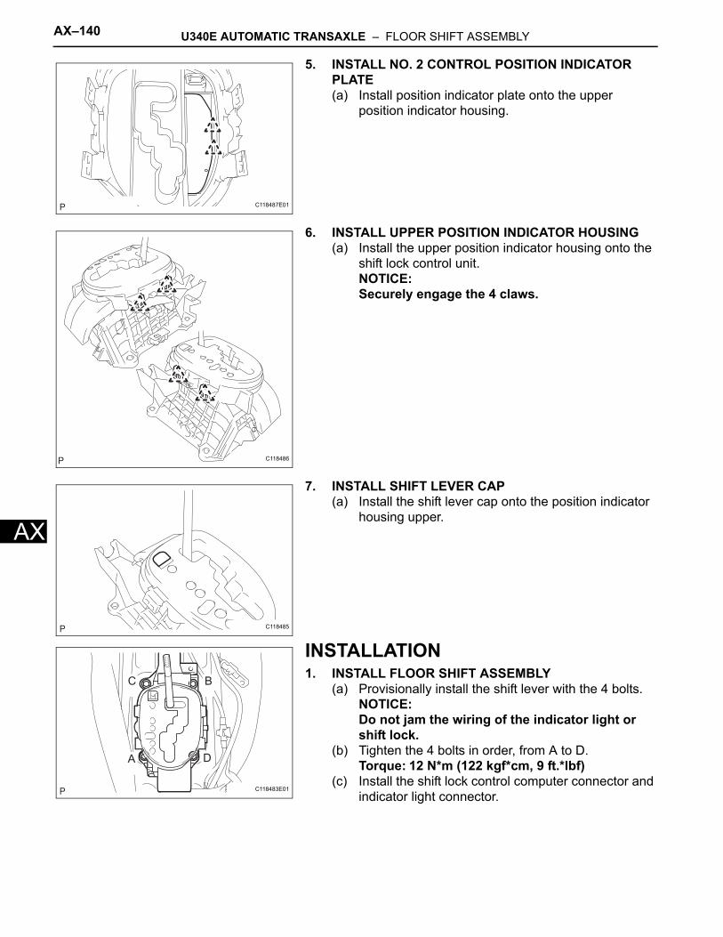
AX–140 U340E AUTOMATIC TRANSAXLE – FLOOR SHIFT ASSEMBLY
AX
5. INSTALL NO. 2 CONTROL POSITION INDICATOR PLATE(a) Install position indicator plate onto the upper
position indicator housing.
6. INSTALL UPPER POSITION INDICATOR HOUSING(a) Install the upper position indicator housing onto the
shift lock control unit.NOTICE:Securely engage the 4 claws.
7. INSTALL SHIFT LEVER CAP(a) Install the shift lever cap onto the position indicator
housing upper.
INSTALLATION1. INSTALL FLOOR SHIFT ASSEMBLY
(a) Provisionally install the shift lever with the 4 bolts.NOTICE:Do not jam the wiring of the indicator light or shift lock.
(b) Tighten the 4 bolts in order, from A to D.Torque: 12 N*m (122 kgf*cm, 9 ft.*lbf)
(c) Install the shift lock control computer connector and indicator light connector.
C118487E01
C118486
C118485
A
B
D
C
C118483E01
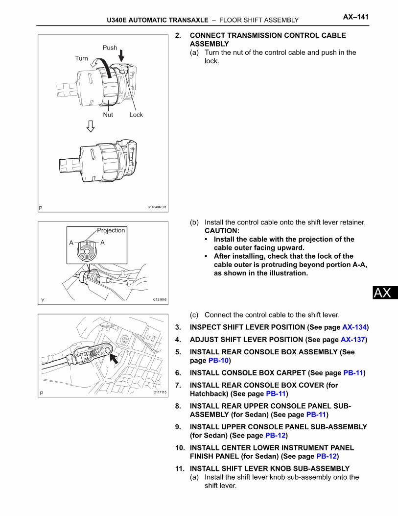
U340E AUTOMATIC TRANSAXLE – FLOOR SHIFT ASSEMBLY AX–141
X
A2. CONNECT TRANSMISSION CONTROL CABLE ASSEMBLY(a) Turn the nut of the control cable and push in the
lock.
(b) Install the control cable onto the shift lever retainer.CAUTION:• Install the cable with the projection of the
cable outer facing upward.• After installing, check that the lock of the
cable outer is protruding beyond portion A-A, as shown in the illustration.
(c) Connect the control cable to the shift lever.
3. INSPECT SHIFT LEVER POSITION (See page AX-134)4. ADJUST SHIFT LEVER POSITION (See page AX-137)5. INSTALL REAR CONSOLE BOX ASSEMBLY (See
page PB-10)6. INSTALL CONSOLE BOX CARPET (See page PB-11)7. INSTALL REAR CONSOLE BOX COVER (for
Hatchback) (See page PB-11)8. INSTALL REAR UPPER CONSOLE PANEL SUB-
ASSEMBLY (for Sedan) (See page PB-11)9. INSTALL UPPER CONSOLE PANEL SUB-ASSEMBLY
(for Sedan) (See page PB-12)10. INSTALL CENTER LOWER INSTRUMENT PANEL
FINISH PANEL (for Sedan) (See page PB-12)11. INSTALL SHIFT LEVER KNOB SUB-ASSEMBLY
(a) Install the shift lever knob sub-assembly onto the shift lever.
Push
Turn
Nut Lock
C118484E01
A A
Projection
C121646
C117115
AX–142 U340E AUTOMATIC TRANSAXLE – FLOOR SHIFT ASSEMBLY
AX
12. CONNECT CABLE TO NEGATIVE BATTERY TERMINALTorque: 5.4 N*m (55 kgf*cm, 48 in.*lbf)
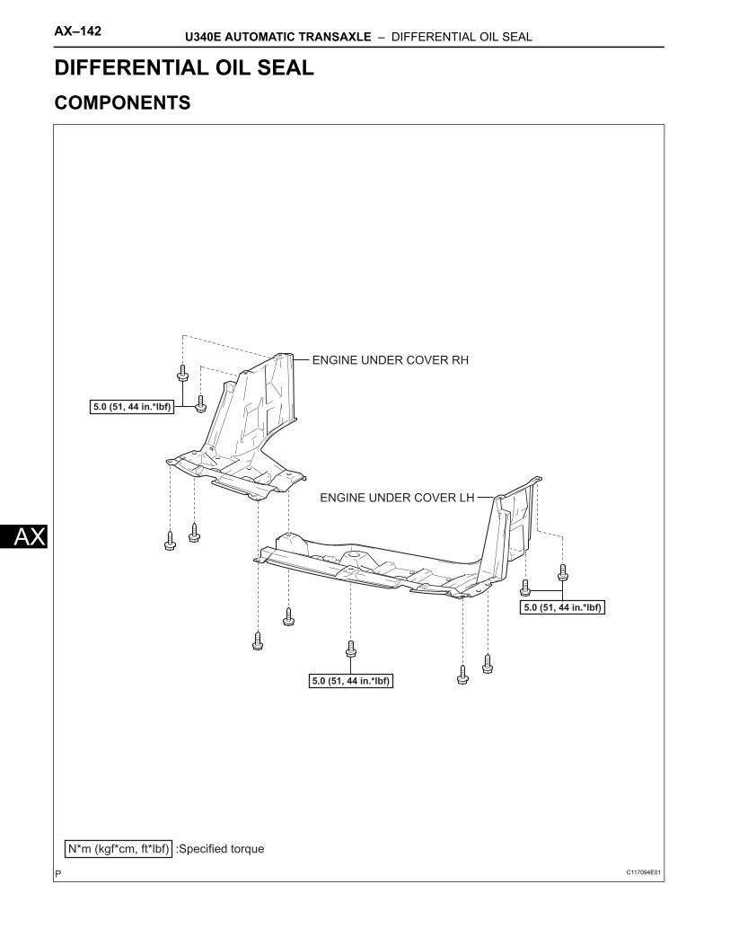
AX–142 U340E AUTOMATIC TRANSAXLE – DIFFERENTIAL OIL SEAL
AX
TRANSMISSIONU340E AUTOMATIC TRANSAXLEDIFFERENTIAL OIL SEALCOMPONENTS
ENGINE UNDER COVER LH
ENGINE UNDER COVER RH
N*m (kgf*cm, ft*lbf) :Specified torque
5.0 (51, 44 in.*lbf)
5.0 (51, 44 in.*lbf)
5.0 (51, 44 in.*lbf)
C117094E01

U340E AUTOMATIC TRANSAXLE – DIFFERENTIAL OIL SEAL AX–143
X
AFRONT DRIVE SHAFT ASSEMBLY LH
FRONT DRIVE SHAFT ASSEMBLY RH
FRONT SPEED SENSOR LH
FRONT STABILIZER
LINK ASSEMBLY LH
TIE ROD END
SUB-ASSEMBLY LH
FRONT AXLE HUB NUT LH
74 (755, 55)
CLIP
COTTER PIN
CASTLE NUT
CASTLE NUT
FRONT DRIVE SHAFT
RH HOLE SNAP RING
FRONT DRIVE SHAFT
LH HOLE SNAP RING
98 (1,000, 72)
216 (2,203, 160)
8.5 (87, 75 in.*lbf)
49 (500, 36)
N*m (kgf*cm, ft*lbf) : Specified torque
Non-reusable part
w/ ABS:
FRONT LOWER
SUSPENSION ARM LH
C117093E05
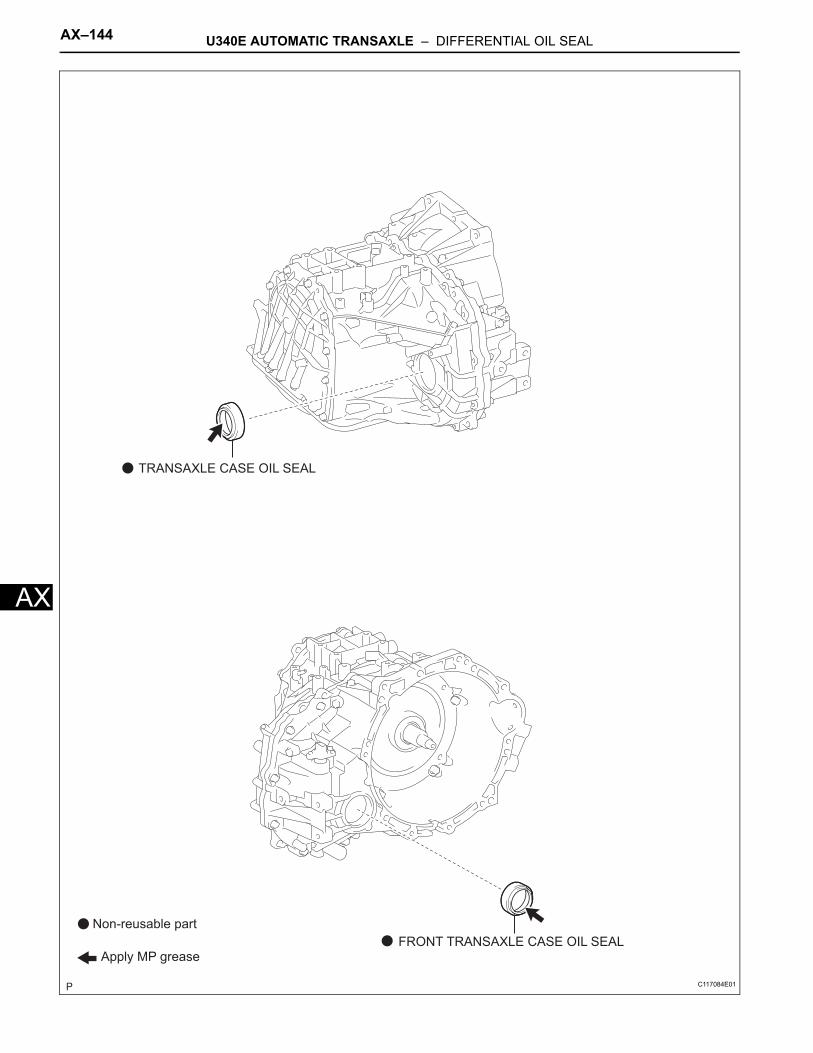
AX–144 U340E AUTOMATIC TRANSAXLE – DIFFERENTIAL OIL SEAL
AX
TRANSAXLE CASE OIL SEAL
FRONT TRANSAXLE CASE OIL SEAL
Non-reusable part
Apply MP grease
C117084E01
U340E AUTOMATIC TRANSAXLE – DIFFERENTIAL OIL SEAL AX–145
X
AREMOVAL1. DISCONNECT CABLE FROM NEGATIVE BATTERY
TERMINAL2. REMOVE FRONT WHEELS3. REMOVE ENGINE UNDER COVER LH4. REMOVE ENGINE UNDER COVER RH5. DRAIN AUTOMATIC TRANSAXLE FLUID
(a) Remove the drain plug and gasket, and drain the automatic transaxle fluid.
(b) Install a new gasket and the drain plug.Torque: 49 N*m (500 kgf*cm, 36 ft.*lbf)
6. REMOVE FRONT AXLE HUB NUT LH (See page DS-3)
7. REMOVE FRONT AXLE HUB NUT RHHINT:The removal procedure for the RH side is the same as that for the LH side.
8. SEPARATE FRONT SPEED SENSOR LH (w/ ABS) (See page DS-3)
9. SEPARATE FRONT SPEED SENSOR RH (w/ ABS)HINT:The separation procedure for the RH side is the same as that for the LH side.
10. SEPARATE FRONT STABILIZER LINK ASSEMBLY LH (See page DS-4)
11. SEPARATE FRONT STABILIZER LINK ASSEMBLY RHHINT:The separation procedure for the RH side is the same as that for the LH side.
12. SEPARATE TIE ROD END SUB-ASSEMBLY LH (See page DS-3)
13. SEPARATE TIE ROD END SUB-ASSEMBLY RHHINT:The separation procedure for the RH side is the same as that for the LH side.
14. SEPARATE FRONT LOWER SUSPENSION ARM LH (See page DS-4)
15. SEPARATE FRONT LOWER SUSPENSION ARM RHHINT:The separation procedure for the RH side is the same as that for the LH side.
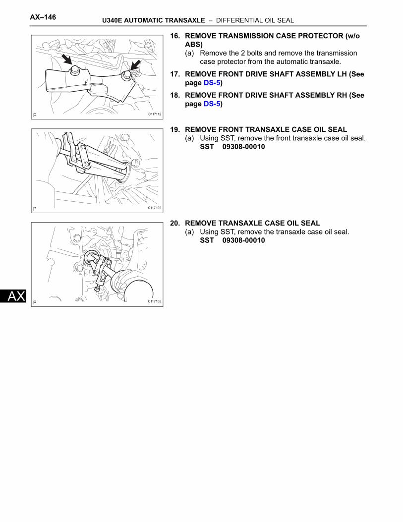
AX–146 U340E AUTOMATIC TRANSAXLE – DIFFERENTIAL OIL SEAL
AX
16. REMOVE TRANSMISSION CASE PROTECTOR (w/o ABS)(a) Remove the 2 bolts and remove the transmission
case protector from the automatic transaxle.
17. REMOVE FRONT DRIVE SHAFT ASSEMBLY LH (See page DS-5)
18. REMOVE FRONT DRIVE SHAFT ASSEMBLY RH (See page DS-5)
19. REMOVE FRONT TRANSAXLE CASE OIL SEAL(a) Using SST, remove the front transaxle case oil seal.
SST 09308-00010
20. REMOVE TRANSAXLE CASE OIL SEAL(a) Using SST, remove the transaxle case oil seal.
SST 09308-00010
C117112
C117109
C117108
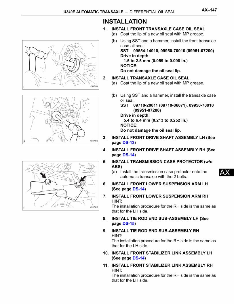
U340E AUTOMATIC TRANSAXLE – DIFFERENTIAL OIL SEAL AX–147
X
AINSTALLATION1. INSTALL FRONT TRANSAXLE CASE OIL SEAL
(a) Coat the lip of a new oil seal with MP grease.(b) Using SST and a hammer, install the front transaxle
case oil seal.SST 09554-14010, 09950-70010 (09951-07200)Drive in depth:
1.5 to 2.5 mm (0.059 to 0.098 in.)NOTICE:Do not damage the oil seal lip.
2. INSTALL TRANSAXLE CASE OIL SEAL(a) Coat the lip of a new oil seal with MP grease.
(b) Using SST and a hammer, install the transaxle case oil seal.SST 09710-20011 (09710-06071), 09950-70010
(09951-07200)Drive in depth:
5.4 to 6.4 mm (0.213 to 0.252 in.)NOTICE:Do not damage the oil seal lip.
3. INSTALL FRONT DRIVE SHAFT ASSEMBLY LH (See page DS-13)
4. INSTALL FRONT DRIVE SHAFT ASSEMBLY RH (See page DS-14)
5. INSTALL TRANSMISSION CASE PROTECTOR (w/o ABS)(a) Install the transmission case protector onto the
automatic transaxle with the 2 bolts.
6. INSTALL FRONT LOWER SUSPENSION ARM LH (See page DS-14)
7. INSTALL FRONT LOWER SUSPENSION ARM RHHINT:The installation procedure for the RH side is the same as that for the LH side.
8. INSTALL TIE ROD END SUB-ASSEMBLY LH (See page DS-15)
9. INSTALL TIE ROD END SUB-ASSEMBLY RHHINT:The installation procedure for the RH side is the same as that for the LH side.
10. INSTALL FRONT STABILIZER LINK ASSEMBLY LH (See page DS-14)
11. INSTALL FRONT STABILIZER LINK ASSEMBLY RHHINT:The installation procedure for the RH side is the same as that for the LH side.
C117111
C117110
C117112
AX–148 U340E AUTOMATIC TRANSAXLE – DIFFERENTIAL OIL SEAL
AX
12. INSTALL FRONT SPEED SENSOR LH (w/ ABS) (See page DS-15)
13. INSTALL FRONT SPEED SENSOR RH (w/ ABS)HINT:The installation procedure for the RH side is the same as that for the LH side.
14. INSTALL FRONT AXLE HUB NUT LH (See page DS-15)
15. INSTALL FRONT AXLE HUB NUT RHHINT:The installation procedure for the RH side is the same as that for the LH side.
16. INSTALL FRONT WHEELSTorque: 103 N*m (1,050 kgf*cm, 76 ft.*lbf)
17. CONNECT CABLE TO NEGATIVE BATTERY TERMINALTorque: 5.4 N*m (55 kgf*cm, 48 in.*lbf)
18. ADD AUTOMATIC TRANSAXLE FLUID (See page AX-170)
19. INSPECT AUTOMATIC TRANSAXLE FLUID (See page AX-93)
20. CHECK AUTOMATIC TRANSAXLE FLUID LEAKAGE21. INSPECT AND ADJUST FRONT WHEEL ALIGNMENT
(See page SP-2)
22. INSTALL ENGINE UNDER COVER RH23. INSTALL ENGINE UNDER COVER LH
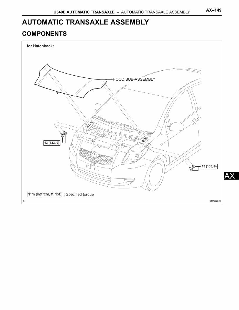
U340E AUTOMATIC TRANSAXLE – AUTOMATIC TRANSAXLE ASSEMBLY AX–149
X
ATRANSMISSIONU340E AUTOMATIC TRANSAXLEAUTOMATIC TRANSAXLE ASSEMBLYCOMPONENTS
HOOD SUB-ASSEMBLY
13 (133, 9)
13 (133, 9)
N*m (kgf*cm, ft.*lbf) : Specified torque
for Hatchback:
C117202E02
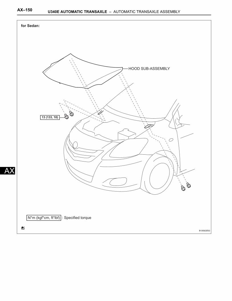
AX–150 U340E AUTOMATIC TRANSAXLE – AUTOMATIC TRANSAXLE ASSEMBLY
AX
HOOD SUB-ASSEMBLY
N*m (kgf*cm, ft*lbf) : Specified torque
13 (133, 10)
for Sedan:
B135922E02
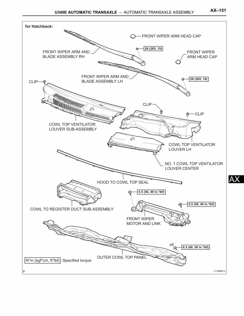
U340E AUTOMATIC TRANSAXLE – AUTOMATIC TRANSAXLE ASSEMBLY AX–151
X
AFRONT WIPER ARM HEAD CAP
FRONT WIPER
MOTOR AND LINK
FRONT WIPER
ARM HEAD CAP
FRONT WIPER ARM AND
BLADE ASSEMBLY LH
FRONT WIPER ARM AND
BLADE ASSEMBLY RH
N*m (kgf*cm, ft*lbf) :Specified torque
5.5 (56, 49 in.*lbf)
26 (265, 19)
26 (265, 19)
5.5 (56, 49 in.*lbf)
x96.5 (66, 58 in.*lbf)
CLIP
CLIP
CLIP
for Hatchback:
NO. 1 COWL TOP VENTILATOR
LOUVER CENTER
COWL TOP VENTILATOR
LOUVER LH
COWL TOP VENTILATOR
LOUVER SUB-ASSEMBLY
HOOD TO COWL TOP SEAL
COWL TO REGISTER DUCT SUB-ASSEMBLY
OUTER COWL TOP PANEL
C116866E10
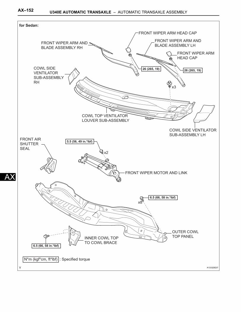
AX–152 U340E AUTOMATIC TRANSAXLE – AUTOMATIC TRANSAXLE ASSEMBLY
AX
6.5 (66, 58 in.*lbf)
6.5 (66, 58 in.*lbf)
for Sedan:
N*m (kgf*cm, ft*lbf) : Specified torque
x2
x8
5.5 (56, 49 in.*lbf)
x3
26 (265, 19)
INNER COWL TOP
TO COWL BRACE
26 (265, 19)
COWL SIDE VENTILATOR
SUB-ASSEMBLY LH
COWL SIDE
VENTILATOR
SUB-ASSEMBLY
RH
COWL TOP VENTILATOR
LOUVER SUB-ASSEMBLY
FRONT AIR
SHUTTER
SEAL
FRONT WIPER ARM AND
BLADE ASSEMBLY LHFRONT WIPER ARM AND
BLADE ASSEMBLY RH
FRONT WIPER ARM HEAD CAP
FRONT WIPER MOTOR AND LINK
OUTER COWL
TOP PANEL
FRONT WIPER ARM
HEAD CAP
A133320E07
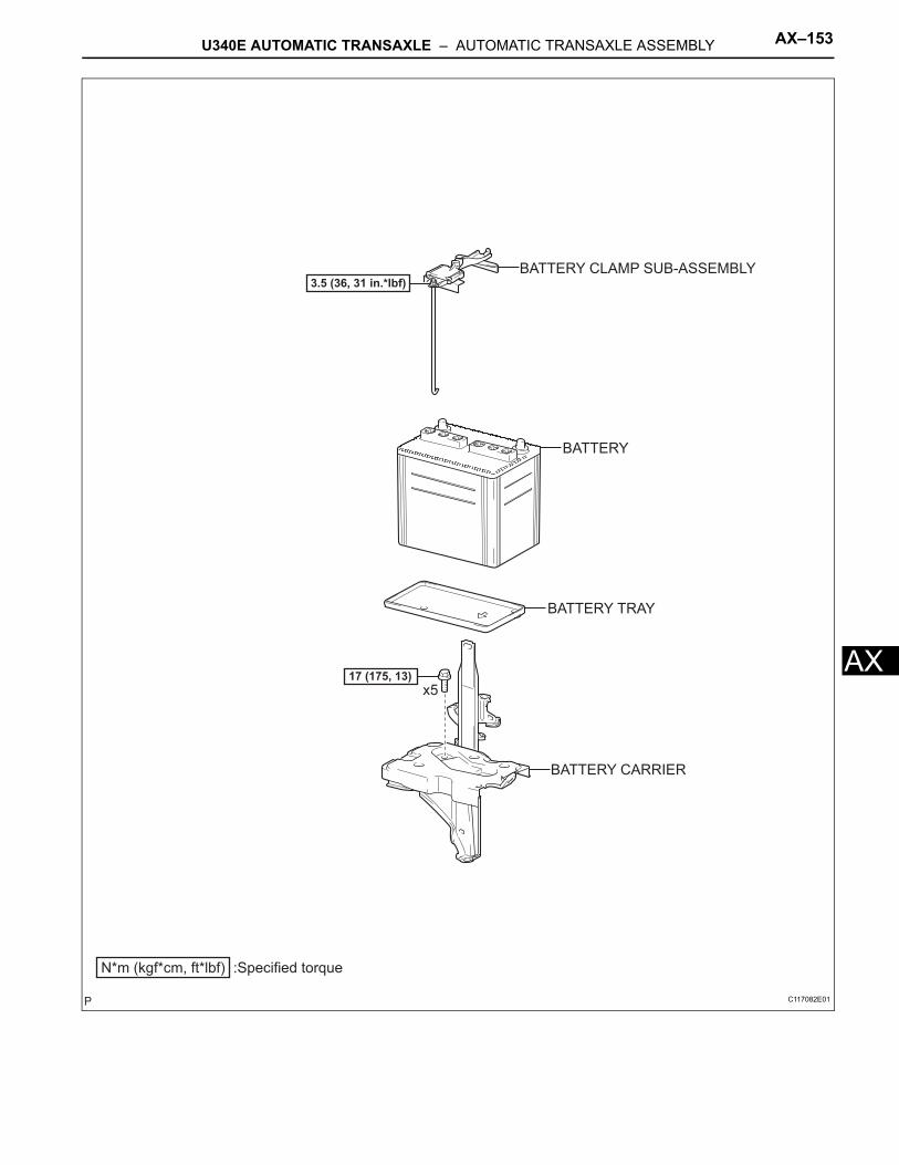
U340E AUTOMATIC TRANSAXLE – AUTOMATIC TRANSAXLE ASSEMBLY AX–153
X
AN*m (kgf*cm, ft*lbf) :Specified torque
3.5 (36, 31 in.*lbf)
17 (175, 13)x5
BATTERY CLAMP SUB-ASSEMBLY
BATTERY
BATTERY TRAY
BATTERY CARRIER
C117082E01
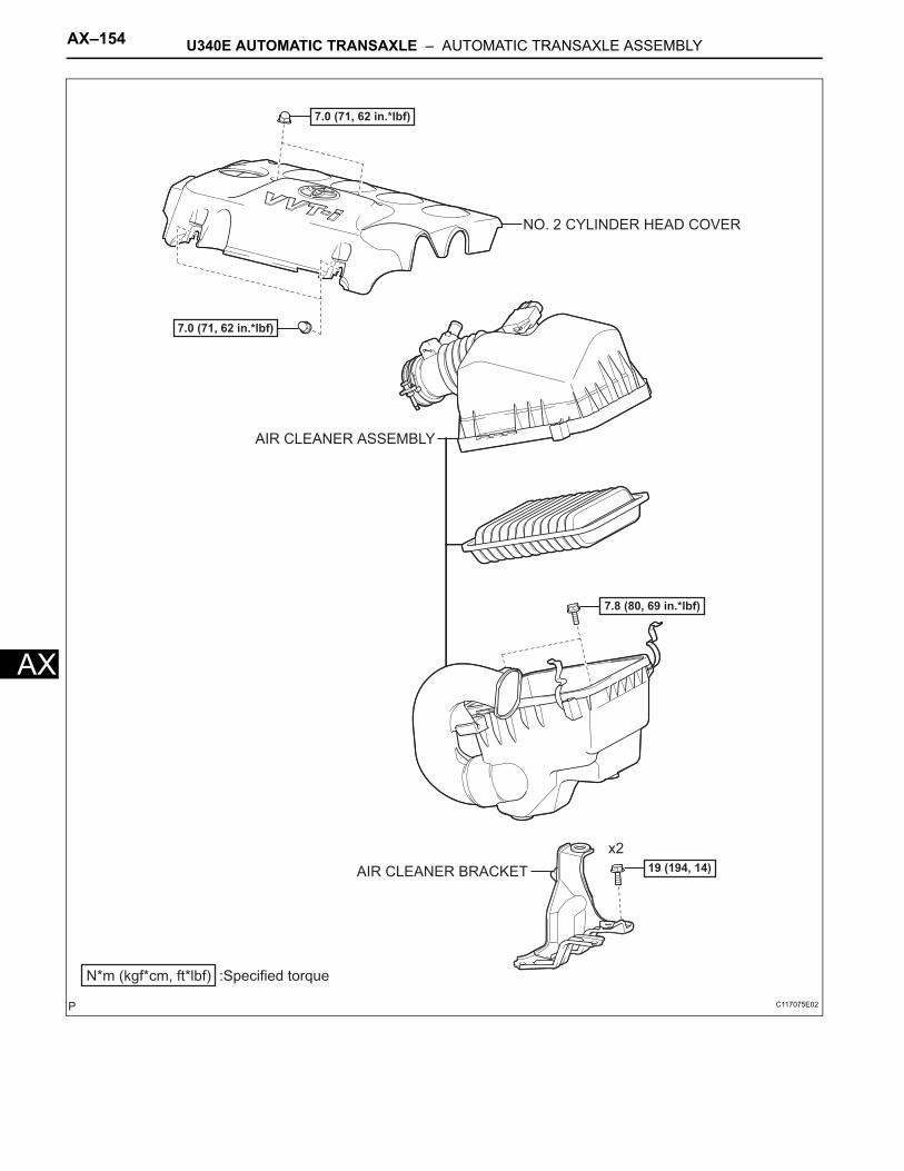
AX–154 U340E AUTOMATIC TRANSAXLE – AUTOMATIC TRANSAXLE ASSEMBLY
AX
AIR CLEANER ASSEMBLY
AIR CLEANER BRACKET
N*m (kgf*cm, ft*lbf) :Specified torque
7.0 (71, 62 in.*lbf)
19 (194, 14)x2
7.8 (80, 69 in.*lbf)
7.0 (71, 62 in.*lbf)
NO. 2 CYLINDER HEAD COVER
C117075E02
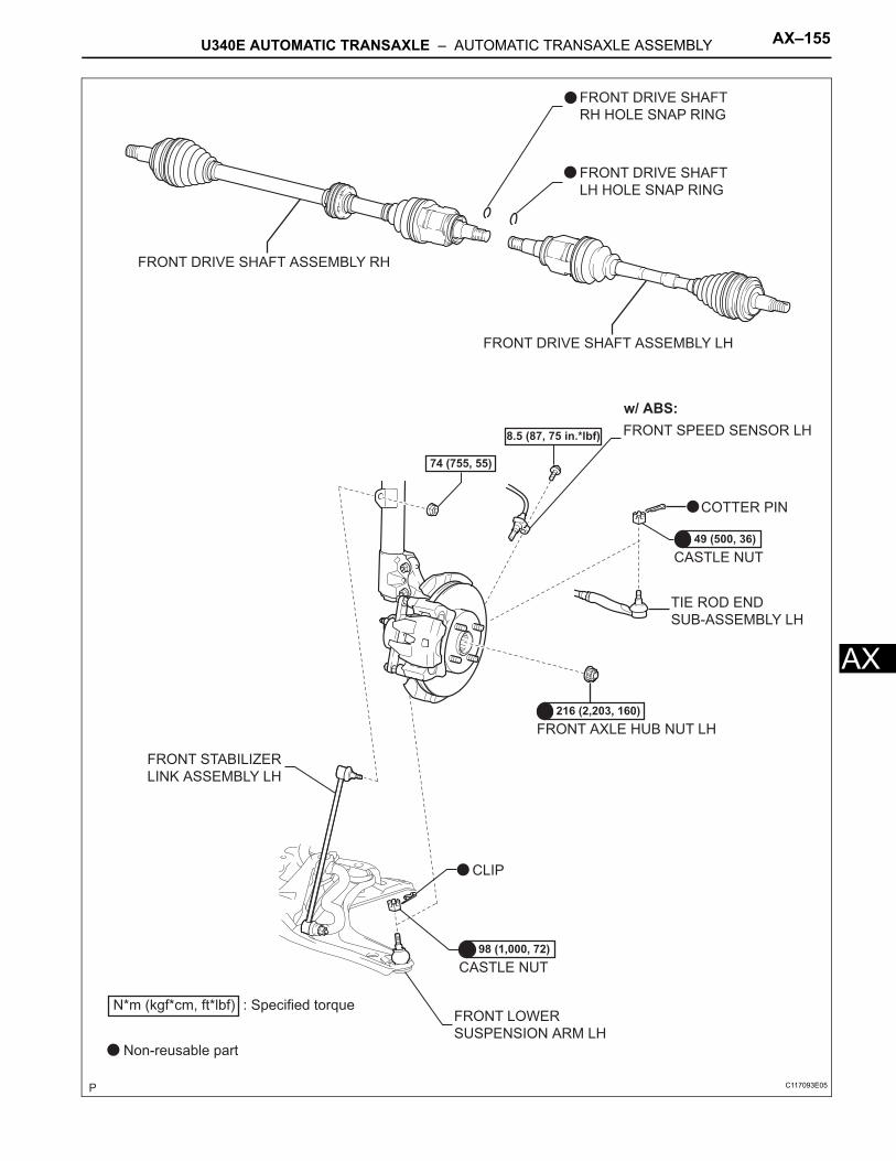
U340E AUTOMATIC TRANSAXLE – AUTOMATIC TRANSAXLE ASSEMBLY AX–155
X
AFRONT DRIVE SHAFT ASSEMBLY LH
FRONT DRIVE SHAFT ASSEMBLY RH
FRONT SPEED SENSOR LH
FRONT STABILIZER
LINK ASSEMBLY LH
TIE ROD END
SUB-ASSEMBLY LH
FRONT AXLE HUB NUT LH
74 (755, 55)
CLIP
COTTER PIN
CASTLE NUT
CASTLE NUT
FRONT DRIVE SHAFT
RH HOLE SNAP RING
FRONT DRIVE SHAFT
LH HOLE SNAP RING
98 (1,000, 72)
216 (2,203, 160)
8.5 (87, 75 in.*lbf)
49 (500, 36)
N*m (kgf*cm, ft*lbf) : Specified torque
Non-reusable part
w/ ABS:
FRONT LOWER
SUSPENSION ARM LH
C117093E05
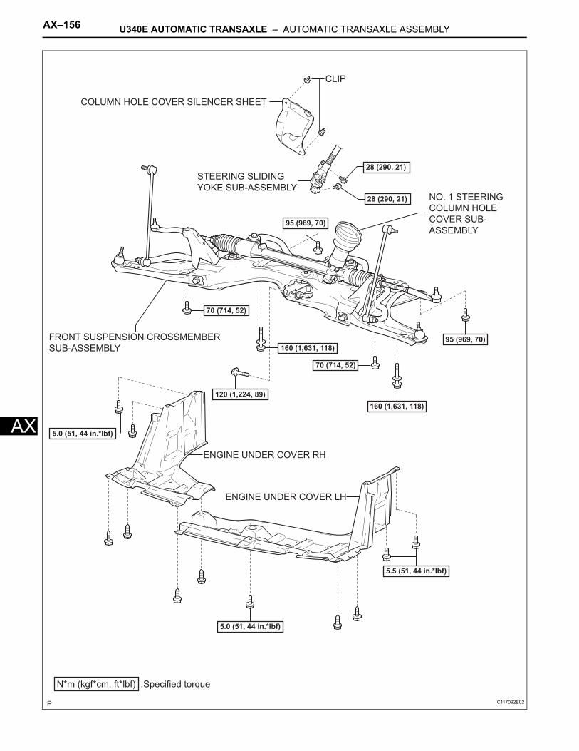
AX–156 U340E AUTOMATIC TRANSAXLE – AUTOMATIC TRANSAXLE ASSEMBLY
AX
COLUMN HOLE COVER SILENCER SHEET
ENGINE UNDER COVER LH
ENGINE UNDER COVER RH
FRONT SUSPENSION CROSSMEMBER
SUB-ASSEMBLY
STEERING SLIDING
YOKE SUB-ASSEMBLY
N*m (kgf*cm, ft*lbf) :Specified torque
70 (714, 52)
28 (290, 21)
95 (969, 70)
160 (1,631, 118)
70 (714, 52)
120 (1,224, 89)
5.5 (51, 44 in.*lbf)
5.0 (51, 44 in.*lbf)
5.0 (51, 44 in.*lbf)
95 (969, 70)
160 (1,631, 118)
CLIP
28 (290, 21)
NO. 1 STEERING
COLUMN HOLE
COVER SUB-
ASSEMBLY
C117092E02
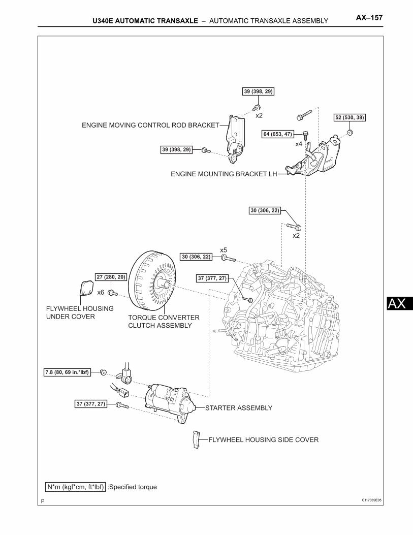
U340E AUTOMATIC TRANSAXLE – AUTOMATIC TRANSAXLE ASSEMBLY AX–157
X
AENGINE MOUNTING BRACKET LH
ENGINE MOVING CONTROL ROD BRACKET
STARTER ASSEMBLY
TORQUE CONVERTER
CLUTCH ASSEMBLY
N*m (kgf*cm, ft*lbf) :Specified torque
37 (377, 27)
27 (280, 20)
30 (306, 22)
30 (306, 22)
37 (377, 27)
39 (398, 29)
39 (398, 29)
52 (530, 38)
FLYWHEEL HOUSING
UNDER COVER
FLYWHEEL HOUSING SIDE COVER
64 (653, 47)
x6
x2
x5
x2
x4
7.8 (80, 69 in.*lbf)
C117089E05
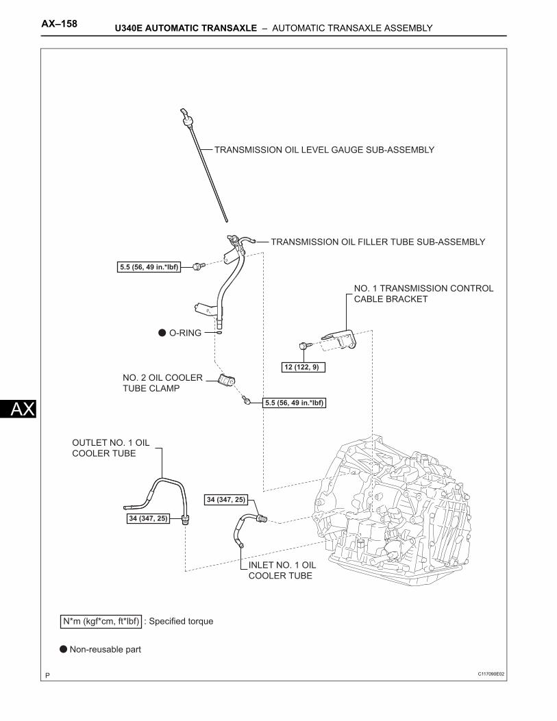
AX–158 U340E AUTOMATIC TRANSAXLE – AUTOMATIC TRANSAXLE ASSEMBLY
AX
TRANSMISSION OIL FILLER TUBE SUB-ASSEMBLY
TRANSMISSION OIL LEVEL GAUGE SUB-ASSEMBLY
O-RING
5.5 (56, 49 in.*lbf)
34 (347, 25)
5.5 (56, 49 in.*lbf)
34 (347, 25)
12 (122, 9)
N*m (kgf*cm, ft*lbf) : Specified torque
Non-reusable part
INLET NO. 1 OIL
COOLER TUBE
NO. 1 TRANSMISSION CONTROL
CABLE BRACKET
NO. 2 OIL COOLER
TUBE CLAMP
OUTLET NO. 1 OIL
COOLER TUBE
C117090E02
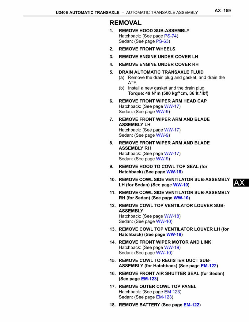
U340E AUTOMATIC TRANSAXLE – AUTOMATIC TRANSAXLE ASSEMBLY AX–159
X
AREMOVAL1. REMOVE HOOD SUB-ASSEMBLY
Hatchback: (See page PS-74)Sedan: (See page PS-63)
2. REMOVE FRONT WHEELS3. REMOVE ENGINE UNDER COVER LH4. REMOVE ENGINE UNDER COVER RH5. DRAIN AUTOMATIC TRANSAXLE FLUID
(a) Remove the drain plug and gasket, and drain the ATF.
(b) Install a new gasket and the drain plug.Torque: 49 N*m (500 kgf*cm, 36 ft.*lbf)
6. REMOVE FRONT WIPER ARM HEAD CAPHatchback: (See page WW-17)Sedan: (See page WW-9)
7. REMOVE FRONT WIPER ARM AND BLADE ASSEMBLY LHHatchback: (See page WW-17)Sedan: (See page WW-9)
8. REMOVE FRONT WIPER ARM AND BLADE ASSEMBLY RHHatchback: (See page WW-17)Sedan: (See page WW-9)
9. REMOVE HOOD TO COWL TOP SEAL (for Hatchback) (See page WW-18)
10. REMOVE COWL SIDE VENTILATOR SUB-ASSEMBLY LH (for Sedan) (See page WW-10)
11. REMOVE COWL SIDE VENTILATOR SUB-ASSEMBLY RH (for Sedan) (See page WW-10)
12. REMOVE COWL TOP VENTILATOR LOUVER SUB-ASSEMBLYHatchback: (See page WW-18)Sedan: (See page WW-10)
13. REMOVE COWL TOP VENTILATOR LOUVER LH (for Hatchback) (See page WW-18)
14. REMOVE FRONT WIPER MOTOR AND LINKHatchback: (See page WW-19)Sedan: (See page WW-10)
15. REMOVE COWL TO REGISTER DUCT SUB-ASSEMBLY (for Hatchback) (See page EM-122)
16. REMOVE FRONT AIR SHUTTER SEAL (for Sedan) (See page EM-123)
17. REMOVE OUTER COWL TOP PANELHatchback: (See page EM-123)Sedan: (See page EM-123)
18. REMOVE BATTERY (See page EM-122)
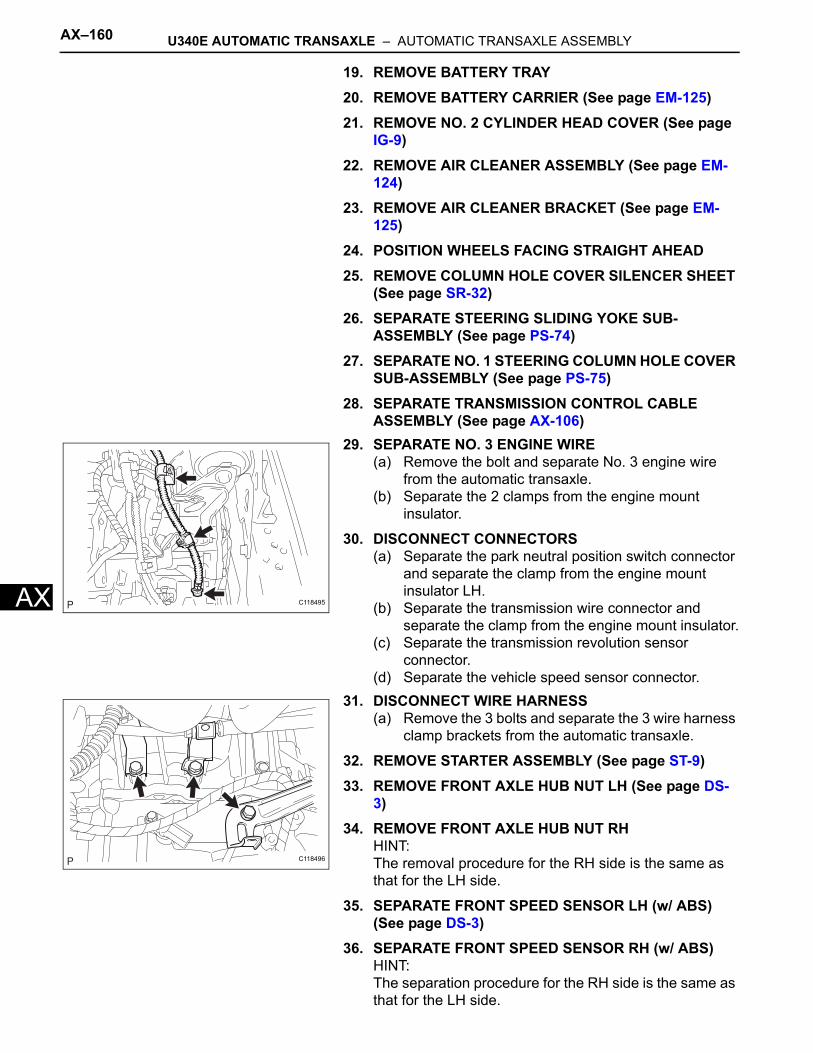
AX–160 U340E AUTOMATIC TRANSAXLE – AUTOMATIC TRANSAXLE ASSEMBLY
AX
19. REMOVE BATTERY TRAY20. REMOVE BATTERY CARRIER (See page EM-125)21. REMOVE NO. 2 CYLINDER HEAD COVER (See page
IG-9)22. REMOVE AIR CLEANER ASSEMBLY (See page EM-
124)23. REMOVE AIR CLEANER BRACKET (See page EM-
125)24. POSITION WHEELS FACING STRAIGHT AHEAD25. REMOVE COLUMN HOLE COVER SILENCER SHEET
(See page SR-32)26. SEPARATE STEERING SLIDING YOKE SUB-
ASSEMBLY (See page PS-74)27. SEPARATE NO. 1 STEERING COLUMN HOLE COVER
SUB-ASSEMBLY (See page PS-75)28. SEPARATE TRANSMISSION CONTROL CABLE
ASSEMBLY (See page AX-106)29. SEPARATE NO. 3 ENGINE WIRE
(a) Remove the bolt and separate No. 3 engine wire from the automatic transaxle.
(b) Separate the 2 clamps from the engine mount insulator.
30. DISCONNECT CONNECTORS(a) Separate the park neutral position switch connector
and separate the clamp from the engine mount insulator LH.
(b) Separate the transmission wire connector and separate the clamp from the engine mount insulator.
(c) Separate the transmission revolution sensor connector.
(d) Separate the vehicle speed sensor connector.31. DISCONNECT WIRE HARNESS
(a) Remove the 3 bolts and separate the 3 wire harness clamp brackets from the automatic transaxle.
32. REMOVE STARTER ASSEMBLY (See page ST-9)33. REMOVE FRONT AXLE HUB NUT LH (See page DS-
3)34. REMOVE FRONT AXLE HUB NUT RH
HINT:The removal procedure for the RH side is the same as that for the LH side.
35. SEPARATE FRONT SPEED SENSOR LH (w/ ABS) (See page DS-3)
36. SEPARATE FRONT SPEED SENSOR RH (w/ ABS)HINT:The separation procedure for the RH side is the same as that for the LH side.
C118495
C118496
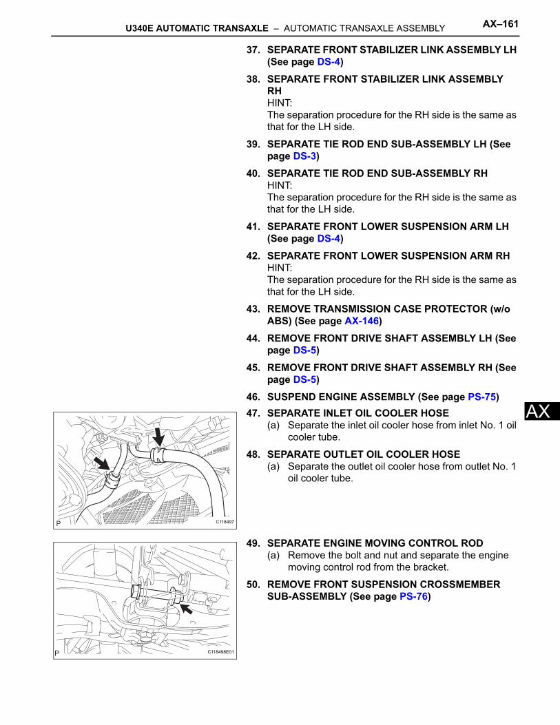
U340E AUTOMATIC TRANSAXLE – AUTOMATIC TRANSAXLE ASSEMBLY AX–161
X
A37. SEPARATE FRONT STABILIZER LINK ASSEMBLY LH (See page DS-4)
38. SEPARATE FRONT STABILIZER LINK ASSEMBLY RHHINT:The separation procedure for the RH side is the same as that for the LH side.
39. SEPARATE TIE ROD END SUB-ASSEMBLY LH (See page DS-3)
40. SEPARATE TIE ROD END SUB-ASSEMBLY RHHINT:The separation procedure for the RH side is the same as that for the LH side.
41. SEPARATE FRONT LOWER SUSPENSION ARM LH (See page DS-4)
42. SEPARATE FRONT LOWER SUSPENSION ARM RHHINT:The separation procedure for the RH side is the same as that for the LH side.
43. REMOVE TRANSMISSION CASE PROTECTOR (w/o ABS) (See page AX-146)
44. REMOVE FRONT DRIVE SHAFT ASSEMBLY LH (See page DS-5)
45. REMOVE FRONT DRIVE SHAFT ASSEMBLY RH (See page DS-5)
46. SUSPEND ENGINE ASSEMBLY (See page PS-75)47. SEPARATE INLET OIL COOLER HOSE
(a) Separate the inlet oil cooler hose from inlet No. 1 oil cooler tube.
48. SEPARATE OUTLET OIL COOLER HOSE(a) Separate the outlet oil cooler hose from outlet No. 1
oil cooler tube.
49. SEPARATE ENGINE MOVING CONTROL ROD(a) Remove the bolt and nut and separate the engine
moving control rod from the bracket.
50. REMOVE FRONT SUSPENSION CROSSMEMBER SUB-ASSEMBLY (See page PS-76)
C118497
C118498E01
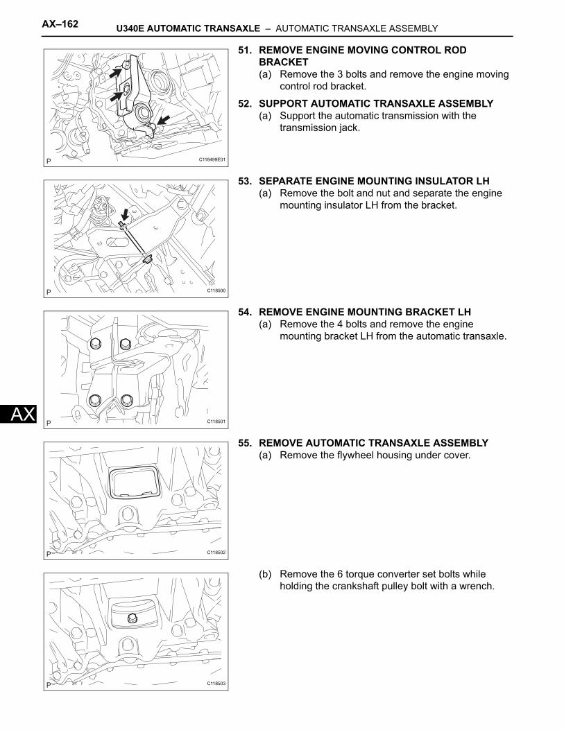
AX–162 U340E AUTOMATIC TRANSAXLE – AUTOMATIC TRANSAXLE ASSEMBLY
AX
51. REMOVE ENGINE MOVING CONTROL ROD BRACKET(a) Remove the 3 bolts and remove the engine moving
control rod bracket.
52. SUPPORT AUTOMATIC TRANSAXLE ASSEMBLY(a) Support the automatic transmission with the
transmission jack.
53. SEPARATE ENGINE MOUNTING INSULATOR LH(a) Remove the bolt and nut and separate the engine
mounting insulator LH from the bracket.
54. REMOVE ENGINE MOUNTING BRACKET LH(a) Remove the 4 bolts and remove the engine
mounting bracket LH from the automatic transaxle.
55. REMOVE AUTOMATIC TRANSAXLE ASSEMBLY(a) Remove the flywheel housing under cover.
(b) Remove the 6 torque converter set bolts while holding the crankshaft pulley bolt with a wrench.
C118499E01
C118500
C118501
C118502
C118503
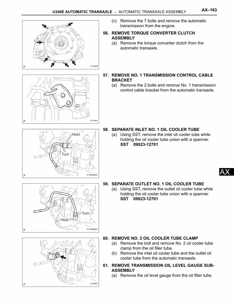
U340E AUTOMATIC TRANSAXLE – AUTOMATIC TRANSAXLE ASSEMBLY AX–163
X
A(c) Remove the 7 bolts and remove the automatic transmission from the engine.
56. REMOVE TORQUE CONVERTER CLUTCH ASSEMBLY(a) Remove the torque converter clutch from the
automatic transaxle.
57. REMOVE NO. 1 TRANSMISSION CONTROL CABLE BRACKET(a) Remove the 2 bolts and remove No. 1 transmission
control cable bracket from the automatic transaxle.
58. SEPARATE INLET NO. 1 OIL COOLER TUBE(a) Using SST, remove the inlet oil cooler tube while
holding the oil cooler tube union with a spanner.SST 09023-12701
59. SEPARATE OUTLET NO. 1 OIL COOLER TUBE(a) Using SST, remove the outlet oil cooler tube while
holding the oil cooler tube union with a spanner.SST 09023-12701
60. REMOVE NO. 2 OIL COOLER TUBE CLAMP(a) Remove the bolt and remove No. 2 oil cooler tube
clamp from the oil filler tube.(b) Remove the inlet oil cooler tube and the outlet oil
cooler tube from the automatic transaxle.
61. REMOVE TRANSMISSION OIL LEVEL GAUGE SUB-ASSEMBLY(a) Remove the oil level gauge from the oil filler tube.
C118504
C121647
Hold
Turn
C118505E01
Turn
Hold
C118506E01
C118507
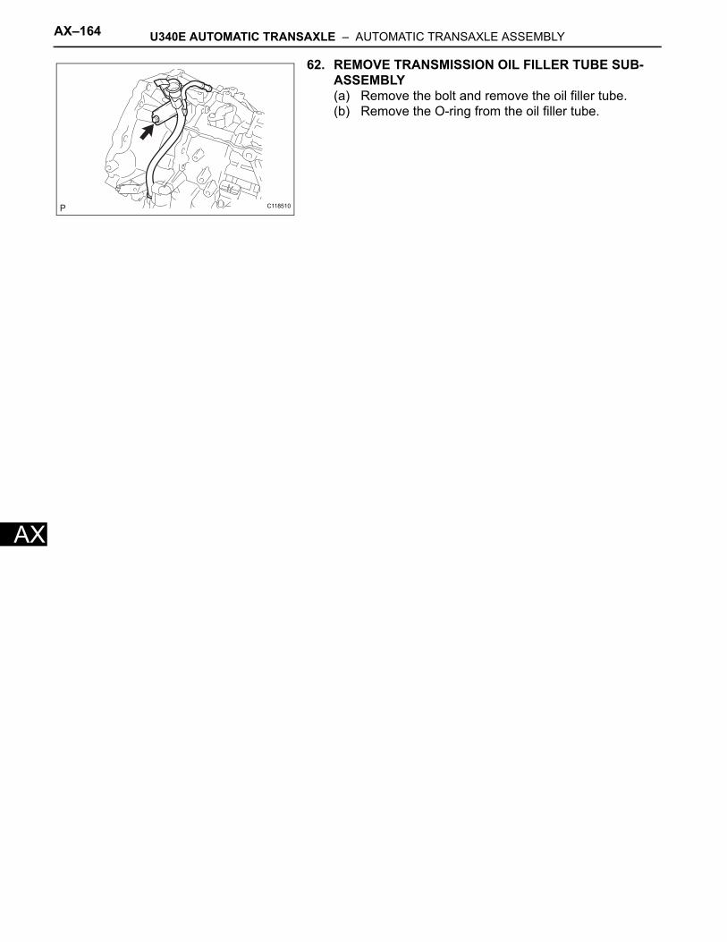
AX–164 U340E AUTOMATIC TRANSAXLE – AUTOMATIC TRANSAXLE ASSEMBLY
AX
62. REMOVE TRANSMISSION OIL FILLER TUBE SUB-ASSEMBLY(a) Remove the bolt and remove the oil filler tube.(b) Remove the O-ring from the oil filler tube.
C118510
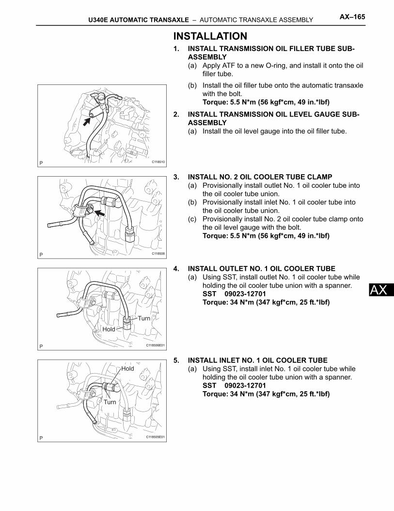
U340E AUTOMATIC TRANSAXLE – AUTOMATIC TRANSAXLE ASSEMBLY AX–165
X
AINSTALLATION1. INSTALL TRANSMISSION OIL FILLER TUBE SUB-
ASSEMBLY(a) Apply ATF to a new O-ring, and install it onto the oil
filler tube.(b) Install the oil filler tube onto the automatic transaxle
with the bolt.Torque: 5.5 N*m (56 kgf*cm, 49 in.*lbf)
2. INSTALL TRANSMISSION OIL LEVEL GAUGE SUB-ASSEMBLY(a) Install the oil level gauge into the oil filler tube.
3. INSTALL NO. 2 OIL COOLER TUBE CLAMP(a) Provisionally install outlet No. 1 oil cooler tube into
the oil cooler tube union.(b) Provisionally install inlet No. 1 oil cooler tube into
the oil cooler tube union.(c) Provisionally install No. 2 oil cooler tube clamp onto
the oil level gauge with the bolt.Torque: 5.5 N*m (56 kgf*cm, 49 in.*lbf)
4. INSTALL OUTLET NO. 1 OIL COOLER TUBE(a) Using SST, install outlet No. 1 oil cooler tube while
holding the oil cooler tube union with a spanner.SST 09023-12701Torque: 34 N*m (347 kgf*cm, 25 ft.*lbf)
5. INSTALL INLET NO. 1 OIL COOLER TUBE(a) Using SST, install inlet No. 1 oil cooler tube while
holding the oil cooler tube union with a spanner.SST 09023-12701Torque: 34 N*m (347 kgf*cm, 25 ft.*lbf)
C118510
C118508
Turn
Hold
C118506E01
Hold
Turn
C118505E01
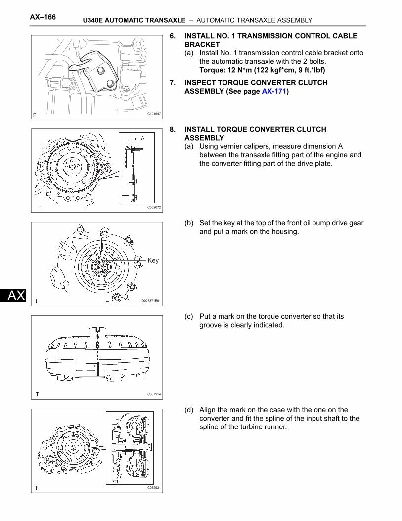
AX–166 U340E AUTOMATIC TRANSAXLE – AUTOMATIC TRANSAXLE ASSEMBLY
AX
6. INSTALL NO. 1 TRANSMISSION CONTROL CABLE BRACKET(a) Install No. 1 transmission control cable bracket onto
the automatic transaxle with the 2 bolts.Torque: 12 N*m (122 kgf*cm, 9 ft.*lbf)
7. INSPECT TORQUE CONVERTER CLUTCH ASSEMBLY (See page AX-171)
8. INSTALL TORQUE CONVERTER CLUTCH ASSEMBLY(a) Using vernier calipers, measure dimension A
between the transaxle fitting part of the engine and the converter fitting part of the drive plate.
(b) Set the key at the top of the front oil pump drive gear and put a mark on the housing.
(c) Put a mark on the torque converter so that its groove is clearly indicated.
(d) Align the mark on the case with the one on the converter and fit the spline of the input shaft to the spline of the turbine runner.
C121647
C062672
Key
D025371E01
C057914
C062931
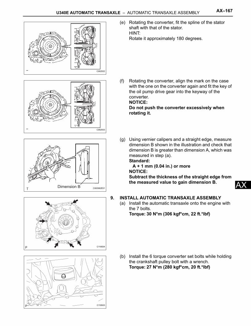
U340E AUTOMATIC TRANSAXLE – AUTOMATIC TRANSAXLE ASSEMBLY AX–167
X
A(e) Rotating the converter, fit the spline of the stator shaft with that of the stator.HINT:Rotate it approximately 180 degrees.
(f) Rotating the converter, align the mark on the case with the one on the converter again and fit the key of the oil pump drive gear into the keyway of the converter.NOTICE:Do not push the converter excessively when rotating it.
(g) Using vernier calipers and a straight edge, measure dimension B shown in the illustration and check that dimension B is greater than dimension A, which was measured in step (a).Standard:
A + 1 mm (0.04 in.) or moreNOTICE:Subtract the thickness of the straight edge from the measured value to gain dimension B.
9. INSTALL AUTOMATIC TRANSAXLE ASSEMBLY(a) Install the automatic transaxle onto the engine with
the 7 bolts.Torque: 30 N*m (306 kgf*cm, 22 ft.*lbf)
(b) Install the 6 torque converter set bolts while holding the crankshaft pulley bolt with a wrench.Torque: 27 N*m (280 kgf*cm, 20 ft.*lbf)
C062932
C062933
Dimension B C063992E01
C118504
C118503
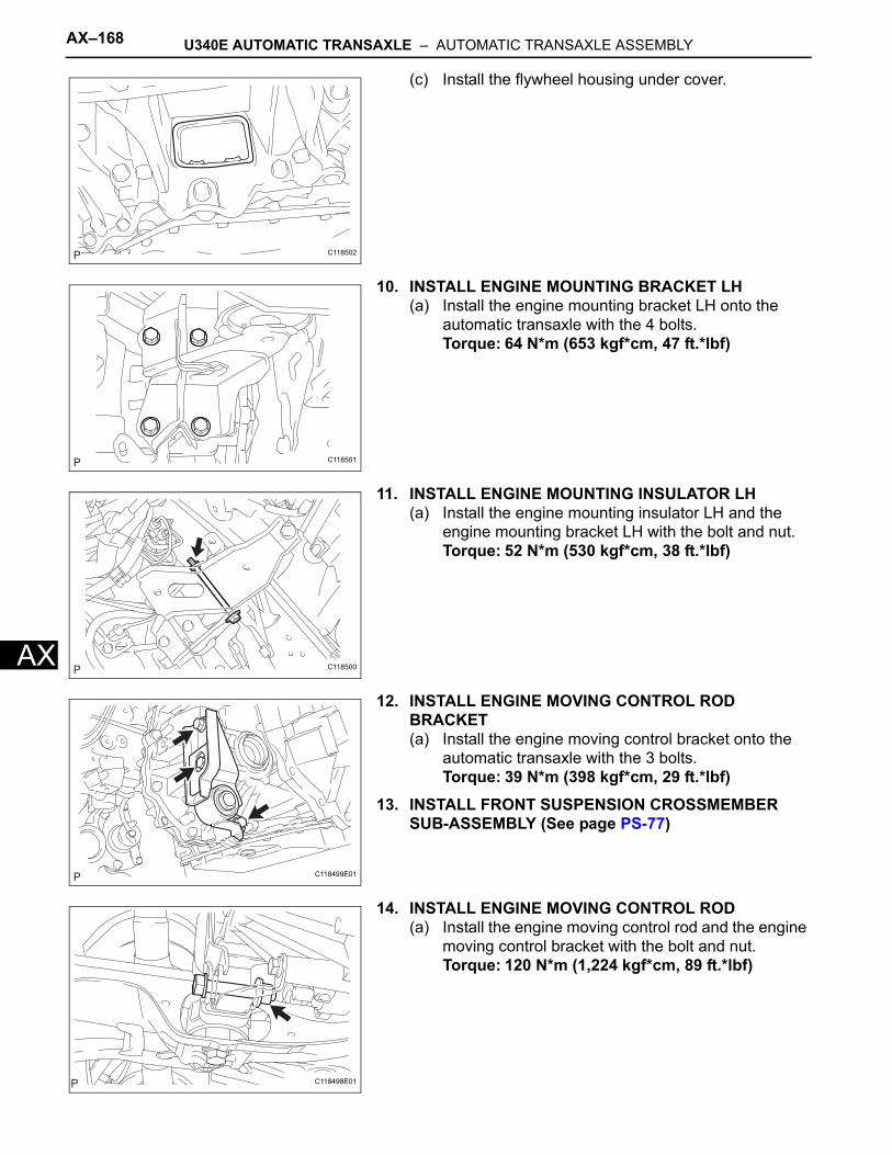
AX–168 U340E AUTOMATIC TRANSAXLE – AUTOMATIC TRANSAXLE ASSEMBLY
AX
(c) Install the flywheel housing under cover.
10. INSTALL ENGINE MOUNTING BRACKET LH(a) Install the engine mounting bracket LH onto the
automatic transaxle with the 4 bolts.Torque: 64 N*m (653 kgf*cm, 47 ft.*lbf)
11. INSTALL ENGINE MOUNTING INSULATOR LH(a) Install the engine mounting insulator LH and the
engine mounting bracket LH with the bolt and nut.Torque: 52 N*m (530 kgf*cm, 38 ft.*lbf)
12. INSTALL ENGINE MOVING CONTROL ROD BRACKET(a) Install the engine moving control bracket onto the
automatic transaxle with the 3 bolts.Torque: 39 N*m (398 kgf*cm, 29 ft.*lbf)
13. INSTALL FRONT SUSPENSION CROSSMEMBER SUB-ASSEMBLY (See page PS-77)
14. INSTALL ENGINE MOVING CONTROL ROD(a) Install the engine moving control rod and the engine
moving control bracket with the bolt and nut.Torque: 120 N*m (1,224 kgf*cm, 89 ft.*lbf)
C118502
C118501
C118500
C118499E01
C118498E01
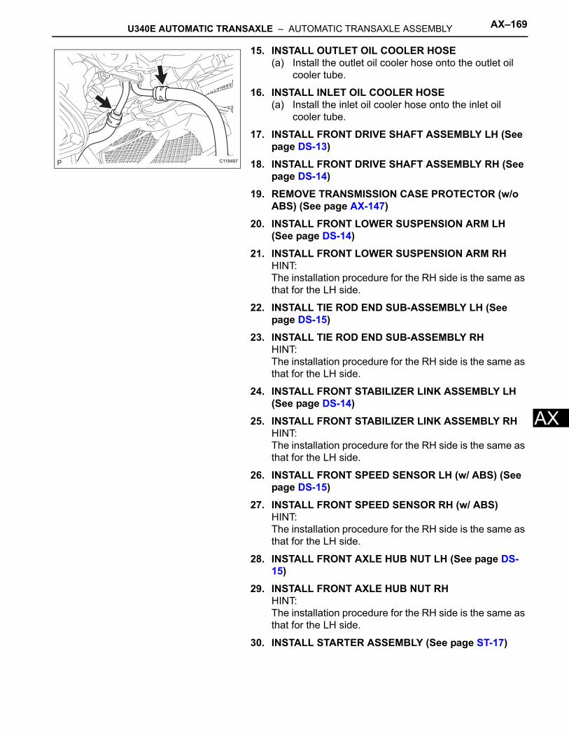
U340E AUTOMATIC TRANSAXLE – AUTOMATIC TRANSAXLE ASSEMBLY AX–169
X
A15. INSTALL OUTLET OIL COOLER HOSE(a) Install the outlet oil cooler hose onto the outlet oil
cooler tube.
16. INSTALL INLET OIL COOLER HOSE(a) Install the inlet oil cooler hose onto the inlet oil
cooler tube.
17. INSTALL FRONT DRIVE SHAFT ASSEMBLY LH (See page DS-13)
18. INSTALL FRONT DRIVE SHAFT ASSEMBLY RH (See page DS-14)
19. REMOVE TRANSMISSION CASE PROTECTOR (w/o ABS) (See page AX-147)
20. INSTALL FRONT LOWER SUSPENSION ARM LH (See page DS-14)
21. INSTALL FRONT LOWER SUSPENSION ARM RHHINT:The installation procedure for the RH side is the same as that for the LH side.
22. INSTALL TIE ROD END SUB-ASSEMBLY LH (See page DS-15)
23. INSTALL TIE ROD END SUB-ASSEMBLY RHHINT:The installation procedure for the RH side is the same as that for the LH side.
24. INSTALL FRONT STABILIZER LINK ASSEMBLY LH (See page DS-14)
25. INSTALL FRONT STABILIZER LINK ASSEMBLY RHHINT:The installation procedure for the RH side is the same as that for the LH side.
26. INSTALL FRONT SPEED SENSOR LH (w/ ABS) (See page DS-15)
27. INSTALL FRONT SPEED SENSOR RH (w/ ABS)HINT:The installation procedure for the RH side is the same as that for the LH side.
28. INSTALL FRONT AXLE HUB NUT LH (See page DS-15)
29. INSTALL FRONT AXLE HUB NUT RHHINT:The installation procedure for the RH side is the same as that for the LH side.
30. INSTALL STARTER ASSEMBLY (See page ST-17)
C118497
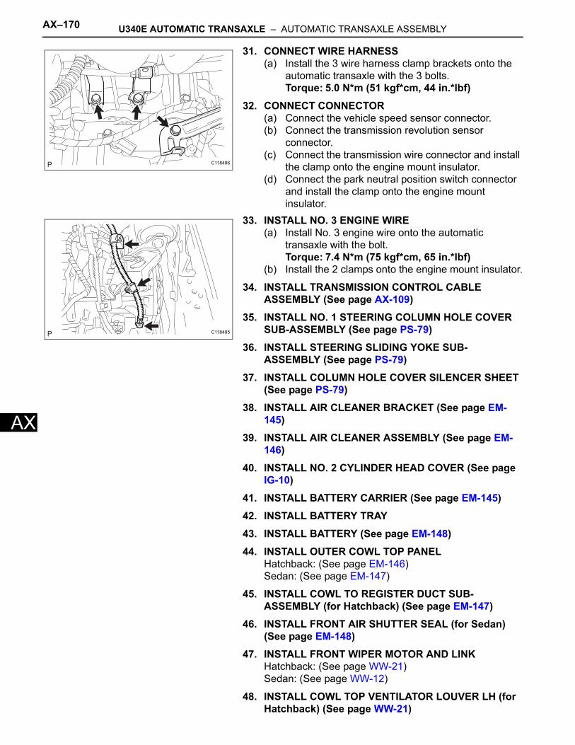
AX–170 U340E AUTOMATIC TRANSAXLE – AUTOMATIC TRANSAXLE ASSEMBLY
AX
31. CONNECT WIRE HARNESS(a) Install the 3 wire harness clamp brackets onto the
automatic transaxle with the 3 bolts.Torque: 5.0 N*m (51 kgf*cm, 44 in.*lbf)
32. CONNECT CONNECTOR(a) Connect the vehicle speed sensor connector.(b) Connect the transmission revolution sensor
connector.(c) Connect the transmission wire connector and install
the clamp onto the engine mount insulator.(d) Connect the park neutral position switch connector
and install the clamp onto the engine mount insulator.
33. INSTALL NO. 3 ENGINE WIRE(a) Install No. 3 engine wire onto the automatic
transaxle with the bolt.Torque: 7.4 N*m (75 kgf*cm, 65 in.*lbf)
(b) Install the 2 clamps onto the engine mount insulator.
34. INSTALL TRANSMISSION CONTROL CABLE ASSEMBLY (See page AX-109)
35. INSTALL NO. 1 STEERING COLUMN HOLE COVER SUB-ASSEMBLY (See page PS-79)
36. INSTALL STEERING SLIDING YOKE SUB-ASSEMBLY (See page PS-79)
37. INSTALL COLUMN HOLE COVER SILENCER SHEET (See page PS-79)
38. INSTALL AIR CLEANER BRACKET (See page EM-145)
39. INSTALL AIR CLEANER ASSEMBLY (See page EM-146)
40. INSTALL NO. 2 CYLINDER HEAD COVER (See page IG-10)
41. INSTALL BATTERY CARRIER (See page EM-145)42. INSTALL BATTERY TRAY43. INSTALL BATTERY (See page EM-148)44. INSTALL OUTER COWL TOP PANEL
Hatchback: (See page EM-146)Sedan: (See page EM-147)
45. INSTALL COWL TO REGISTER DUCT SUB-ASSEMBLY (for Hatchback) (See page EM-147)
46. INSTALL FRONT AIR SHUTTER SEAL (for Sedan) (See page EM-148)
47. INSTALL FRONT WIPER MOTOR AND LINKHatchback: (See page WW-21)Sedan: (See page WW-12)
48. INSTALL COWL TOP VENTILATOR LOUVER LH (for Hatchback) (See page WW-21)
C118496
C118495
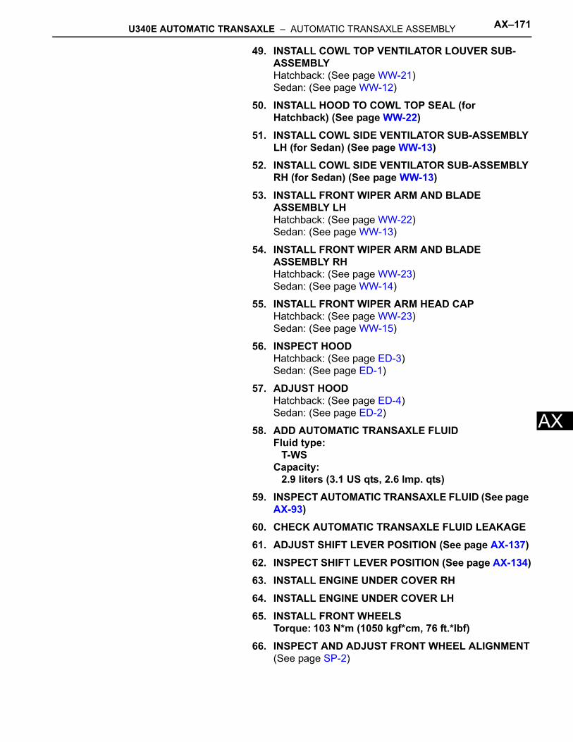
U340E AUTOMATIC TRANSAXLE – AUTOMATIC TRANSAXLE ASSEMBLY AX–171
X
A49. INSTALL COWL TOP VENTILATOR LOUVER SUB-ASSEMBLYHatchback: (See page WW-21)Sedan: (See page WW-12)
50. INSTALL HOOD TO COWL TOP SEAL (for Hatchback) (See page WW-22)
51. INSTALL COWL SIDE VENTILATOR SUB-ASSEMBLY LH (for Sedan) (See page WW-13)
52. INSTALL COWL SIDE VENTILATOR SUB-ASSEMBLY RH (for Sedan) (See page WW-13)
53. INSTALL FRONT WIPER ARM AND BLADE ASSEMBLY LHHatchback: (See page WW-22)Sedan: (See page WW-13)
54. INSTALL FRONT WIPER ARM AND BLADE ASSEMBLY RHHatchback: (See page WW-23)Sedan: (See page WW-14)
55. INSTALL FRONT WIPER ARM HEAD CAPHatchback: (See page WW-23)Sedan: (See page WW-15)
56. INSPECT HOODHatchback: (See page ED-3)Sedan: (See page ED-1)
57. ADJUST HOODHatchback: (See page ED-4)Sedan: (See page ED-2)
58. ADD AUTOMATIC TRANSAXLE FLUIDFluid type:
T-WSCapacity:
2.9 liters (3.1 US qts, 2.6 lmp. qts)59. INSPECT AUTOMATIC TRANSAXLE FLUID (See page
AX-93)60. CHECK AUTOMATIC TRANSAXLE FLUID LEAKAGE61. ADJUST SHIFT LEVER POSITION (See page AX-137)62. INSPECT SHIFT LEVER POSITION (See page AX-134)63. INSTALL ENGINE UNDER COVER RH64. INSTALL ENGINE UNDER COVER LH65. INSTALL FRONT WHEELS
Torque: 103 N*m (1050 kgf*cm, 76 ft.*lbf)66. INSPECT AND ADJUST FRONT WHEEL ALIGNMENT
(See page SP-2)
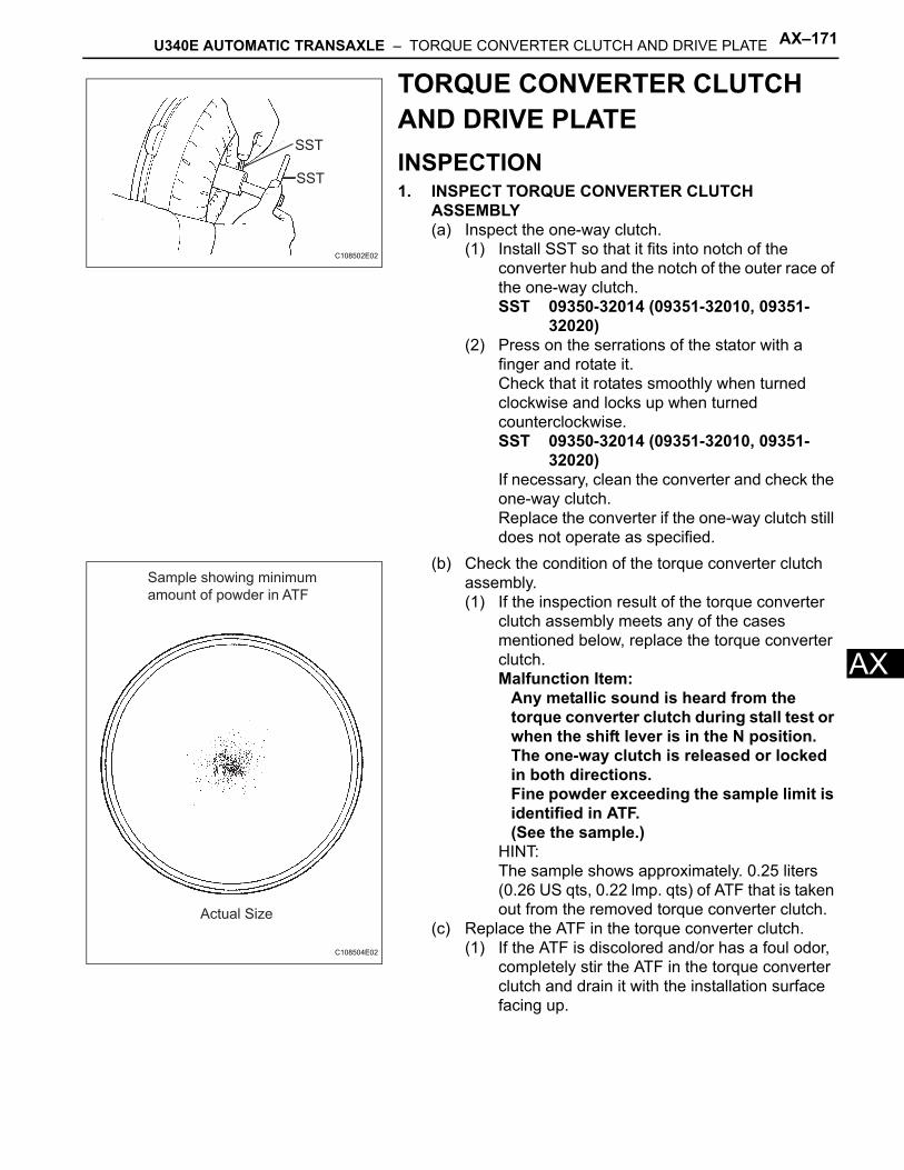
U340E AUTOMATIC TRANSAXLE – TORQUE CONVERTER CLUTCH AND DRIVE PLATE AX–171
X
ATORQUE CONVERTER CLUTCH AND DRIVE PLATEINSPECTION1. INSPECT TORQUE CONVERTER CLUTCH
ASSEMBLY(a) Inspect the one-way clutch.
(1) Install SST so that it fits into notch of the converter hub and the notch of the outer race of the one-way clutch.SST 09350-32014 (09351-32010, 09351-
32020)(2) Press on the serrations of the stator with a
finger and rotate it.Check that it rotates smoothly when turned clockwise and locks up when turned counterclockwise.SST 09350-32014 (09351-32010, 09351-
32020)If necessary, clean the converter and check the one-way clutch.Replace the converter if the one-way clutch still does not operate as specified.
(b) Check the condition of the torque converter clutch assembly.(1) If the inspection result of the torque converter
clutch assembly meets any of the cases mentioned below, replace the torque converter clutch.Malfunction Item:
Any metallic sound is heard from the torque converter clutch during stall test or when the shift lever is in the N position.The one-way clutch is released or locked in both directions.Fine powder exceeding the sample limit is identified in ATF. (See the sample.)
HINT:The sample shows approximately. 0.25 liters (0.26 US qts, 0.22 lmp. qts) of ATF that is taken out from the removed torque converter clutch.
(c) Replace the ATF in the torque converter clutch.(1) If the ATF is discolored and/or has a foul odor,
completely stir the ATF in the torque converter clutch and drain it with the installation surface facing up.
SST
SST
C108502E02
Sample showing minimum
amount of powder in ATF
Actual Size
C108504E02
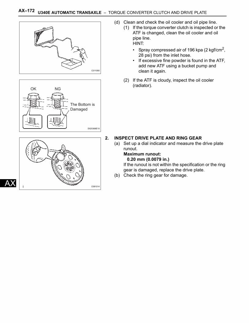
AX–172 U340E AUTOMATIC TRANSAXLE – TORQUE CONVERTER CLUTCH AND DRIVE PLATE
AX
(d) Clean and check the oil cooler and oil pipe line.(1) If the torque converter clutch is inspected or the
ATF is changed, clean the oil cooler and oil pipe line.HINT:• Spray compressed air of 196 kpa (2 kgf/cm2,
28 psi) from the inlet hose.• If excessive fine powder is found in the ATF,
add new ATF using a bucket pump and clean it again.
(2) If the ATF is cloudy, inspect the oil cooler (radiator).
2. INSPECT DRIVE PLATE AND RING GEAR(a) Set up a dial indicator and measure the drive plate
runout.Maximum runout:
0.20 mm (0.0079 in.)If the runout is not within the specification or the ring gear is damaged, replace the drive plate.
(b) Check the ring gear for damage.
C011090
OK NG
The Bottom is
Damaged
D025368E10
C081014
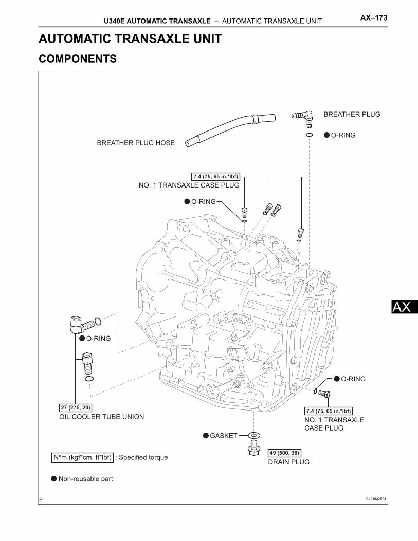
U340E AUTOMATIC TRANSAXLE – AUTOMATIC TRANSAXLE UNIT AX–173
X
ATRANSMISSIONU340E AUTOMATIC TRANSAXLEAUTOMATIC TRANSAXLE UNITCOMPONENTS
OIL COOLER TUBE UNION
O-RING
O-RING
7.4 (75, 65 in.*lbf)
27 (275, 20)
49 (500, 36)
O-RING
DRAIN PLUG
7.4 (75, 65 in.*lbf)
GASKET
O-RING
BREATHER PLUG HOSE
BREATHER PLUG
NO. 1 TRANSAXLE
CASE PLUG
NO. 1 TRANSAXLE CASE PLUG
N*m (kgf*cm, ft*lbf) : Specified torque
Non-reusable part
C121622E03
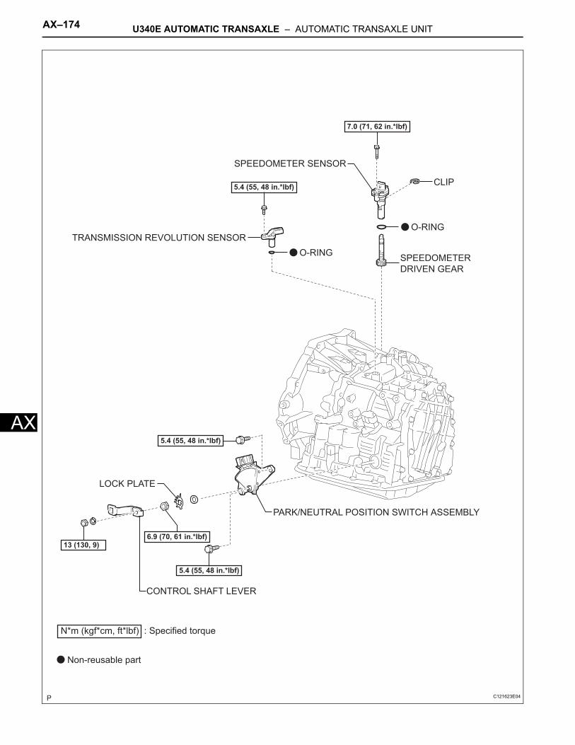
AX–174 U340E AUTOMATIC TRANSAXLE – AUTOMATIC TRANSAXLE UNIT
AX
PARK/NEUTRAL POSITION SWITCH ASSEMBLY
TRANSMISSION REVOLUTION SENSOR
O-RING
5.4 (55, 48 in.*lbf)
13 (130, 9)
O-RING
7.0 (71, 62 in.*lbf)
CLIP
SPEEDOMETER
DRIVEN GEAR
5.4 (55, 48 in.*lbf)
5.4 (55, 48 in.*lbf)
CONTROL SHAFT LEVER
LOCK PLATE
6.9 (70, 61 in.*lbf)
N*m (kgf*cm, ft*lbf) : Specified torque
Non-reusable part
SPEEDOMETER SENSOR
C121623E04
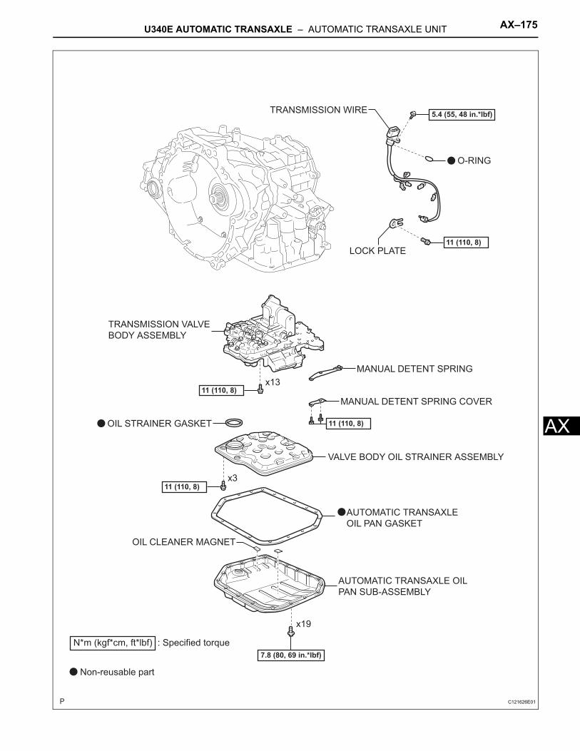
U340E AUTOMATIC TRANSAXLE – AUTOMATIC TRANSAXLE UNIT AX–175
X
AAUTOMATIC TRANSAXLE OIL
PAN SUB-ASSEMBLY
TRANSMISSION VALVE
BODY ASSEMBLY
TRANSMISSION WIRE
VALVE BODY OIL STRAINER ASSEMBLY
LOCK PLATE
MANUAL DETENT SPRING
MANUAL DETENT SPRING COVER
OIL STRAINER GASKET
OIL CLEANER MAGNET
7.8 (80, 69 in.*lbf)
11 (110, 8)x3
11 (110, 8)x13
11 (110, 8)
11 (110, 8)
O-RING
5.4 (55, 48 in.*lbf)
x19
N*m (kgf*cm, ft*lbf) : Specified torque
Non-reusable part
AUTOMATIC TRANSAXLE
OIL PAN GASKET
C121626E01
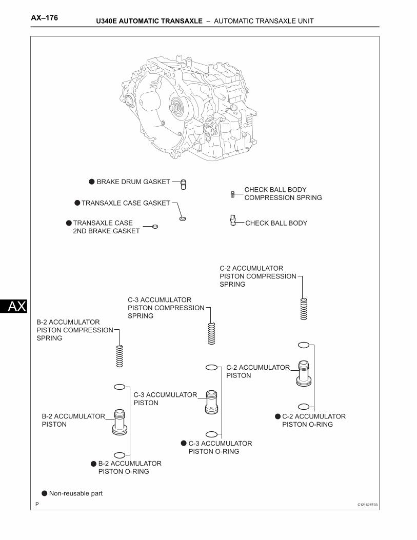
AX–176 U340E AUTOMATIC TRANSAXLE – AUTOMATIC TRANSAXLE UNIT
AX
CHECK BALL BODY
CHECK BALL BODY
COMPRESSION SPRING
B-2 ACCUMULATOR
PISTON COMPRESSION
SPRING
B-2 ACCUMULATOR
PISTON O-RING
C-3 ACCUMULATOR
PISTON COMPRESSION
SPRING
C-3 ACCUMULATOR
PISTON O-RING
C-2 ACCUMULATOR
PISTON O-RING
C-2 ACCUMULATOR
PISTON COMPRESSION
SPRING
Non-reusable part
BRAKE DRUM GASKET
TRANSAXLE CASE
2ND BRAKE GASKET
B-2 ACCUMULATOR
PISTON
C-2 ACCUMULATOR
PISTON
C-3 ACCUMULATOR
PISTON
TRANSAXLE CASE GASKET
C121627E03
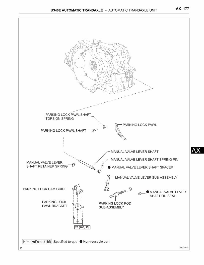
U340E AUTOMATIC TRANSAXLE – AUTOMATIC TRANSAXLE UNIT AX–177
X
AMANUAL VALVE LEVER SHAFTMANUAL VALVE LEVER
SHAFT OIL SEAL
MANUAL VALVE LEVER SUB-ASSEMBLY
PARKING LOCK PAWL
PARKING LOCK
PAWL BRACKETPARKING LOCK ROD
SUB-ASSEMBLY
MANUAL VALVE LEVER SHAFT SPRING PIN
PARKING LOCK PAWL SHAFT
TORSION SPRING
PARKING LOCK PAWL SHAFT
PARKING LOCK CAM GUIDE
N*m (kgf*cm, ft*lbf) :Specified torque Non-reusable part
20 (205, 15)
MANUAL VALVE LEVER SHAFT SPACER
MANUAL VALVE LEVER
SHAFT RETAINER SPRING
C121628E03
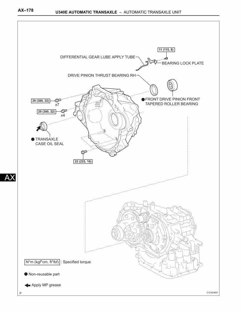
AX–178 U340E AUTOMATIC TRANSAXLE – AUTOMATIC TRANSAXLE UNIT
AX
BEARING LOCK PLATE
DIFFERENTIAL GEAR LUBE APPLY TUBE
FRONT DRIVE PINION FRONT
TAPERED ROLLER BEARING
DRIVE PINION THRUST BEARING RH
22 (225, 16)
Apply MP grease
29 (300, 22)
29 (300, 22)
x4
x7
11 (115, 8)
TRANSAXLE
CASE OIL SEAL
N*m (kgf*cm, ft*lbf) : Specified torque
Non-reusable part
C121624E01
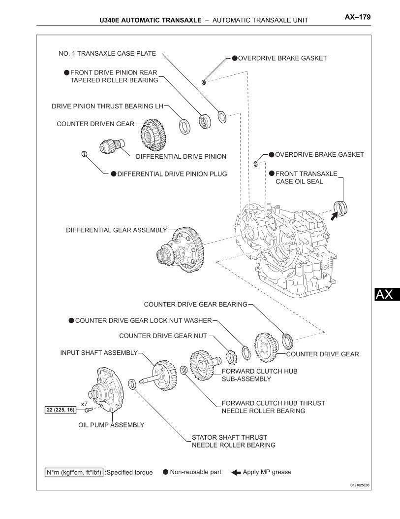
U340E AUTOMATIC TRANSAXLE – AUTOMATIC TRANSAXLE UNIT AX–179
X
AFRONT TRANSAXLE
CASE OIL SEAL
COUNTER DRIVEN GEAR
DIFFERENTIAL DRIVE PINION
DIFFERENTIAL GEAR ASSEMBLY
COUNTER DRIVE GEAR
COUNTER DRIVE GEAR NUT
DRIVE PINION THRUST BEARING LH
COUNTER DRIVE GEAR BEARING
COUNTER DRIVE GEAR LOCK NUT WASHER
FORWARD CLUTCH HUB
SUB-ASSEMBLY
OIL PUMP ASSEMBLY
N*m (kgf*cm, ft*lbf) :Specified torque Non-reusable part
22 (225, 16)
Apply MP grease
x7
NO. 1 TRANSAXLE CASE PLATE
FORWARD CLUTCH HUB THRUST
NEEDLE ROLLER BEARING
OVERDRIVE BRAKE GASKET
OVERDRIVE BRAKE GASKET
DIFFERENTIAL DRIVE PINION PLUG
FRONT DRIVE PINION REAR
TAPERED ROLLER BEARING
INPUT SHAFT ASSEMBLY
STATOR SHAFT THRUST
NEEDLE ROLLER BEARING
C121625E03
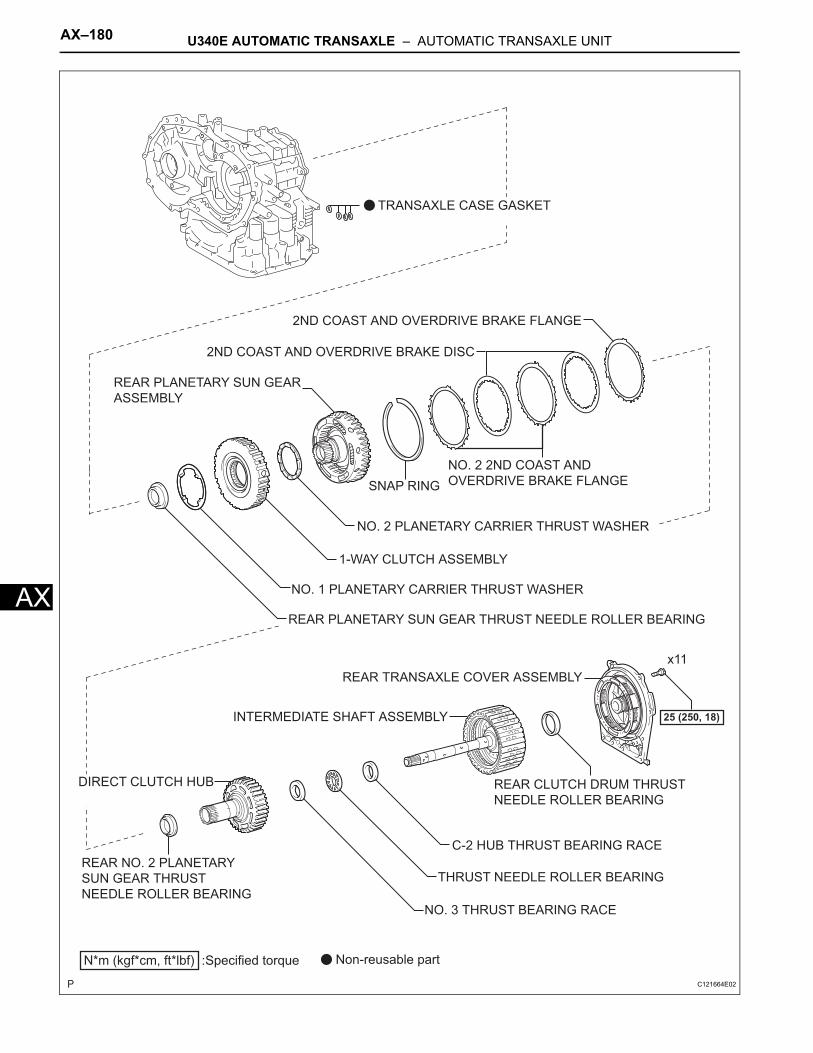
AX–180 U340E AUTOMATIC TRANSAXLE – AUTOMATIC TRANSAXLE UNIT
AX
C-2 HUB THRUST BEARING RACE
NO. 3 THRUST BEARING RACE
2ND COAST AND OVERDRIVE BRAKE DISC
2ND COAST AND OVERDRIVE BRAKE FLANGE
NO. 2 2ND COAST AND
OVERDRIVE BRAKE FLANGESNAP RING
NO. 2 PLANETARY CARRIER THRUST WASHER
REAR PLANETARY SUN GEAR
ASSEMBLY
NO. 1 PLANETARY CARRIER THRUST WASHER
N*m (kgf*cm, ft*lbf) :Specified torque Non-reusable part
25 (250, 18)
x11
1-WAY CLUTCH ASSEMBLY
REAR CLUTCH DRUM THRUST
NEEDLE ROLLER BEARING
THRUST NEEDLE ROLLER BEARING
DIRECT CLUTCH HUB
INTERMEDIATE SHAFT ASSEMBLY
REAR PLANETARY SUN GEAR THRUST NEEDLE ROLLER BEARING
REAR TRANSAXLE COVER ASSEMBLY
TRANSAXLE CASE GASKET
REAR NO. 2 PLANETARY
SUN GEAR THRUST
NEEDLE ROLLER BEARING
C121664E02
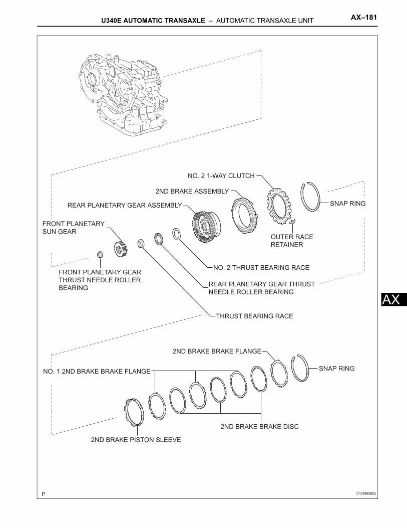
U340E AUTOMATIC TRANSAXLE – AUTOMATIC TRANSAXLE UNIT AX–181
X
A2ND BRAKE BRAKE DISC
OUTER RACE
RETAINER
2ND BRAKE BRAKE FLANGE
NO. 1 2ND BRAKE BRAKE FLANGE SNAP RING
SNAP RING
THRUST BEARING RACE
NO. 2 THRUST BEARING RACEFRONT PLANETARY GEAR
THRUST NEEDLE ROLLER
BEARING
2ND BRAKE ASSEMBLY
NO. 2 1-WAY CLUTCH
2ND BRAKE PISTON SLEEVE
FRONT PLANETARY
SUN GEAR
REAR PLANETARY GEAR ASSEMBLY
REAR PLANETARY GEAR THRUST
NEEDLE ROLLER BEARING
C121665E02
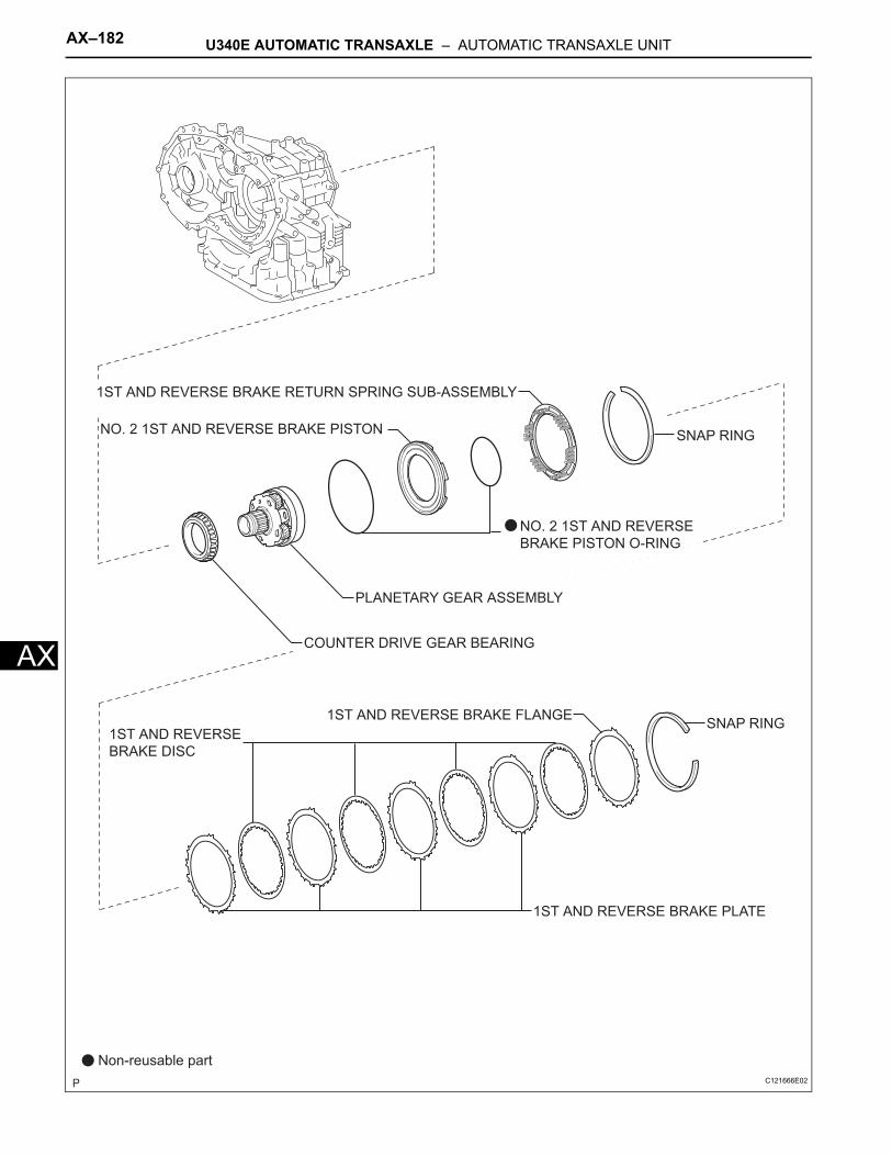
AX–182 U340E AUTOMATIC TRANSAXLE – AUTOMATIC TRANSAXLE UNIT
AX
1ST AND REVERSE
BRAKE DISC
1ST AND REVERSE BRAKE RETURN SPRING SUB-ASSEMBLY
PLANETARY GEAR ASSEMBLY
SNAP RING
SNAP RING
1ST AND REVERSE BRAKE PLATE
1ST AND REVERSE BRAKE FLANGE
Non-reusable part
COUNTER DRIVE GEAR BEARING
NO. 2 1ST AND REVERSE BRAKE PISTON
NO. 2 1ST AND REVERSE
BRAKE PISTON O-RING
C121666E02
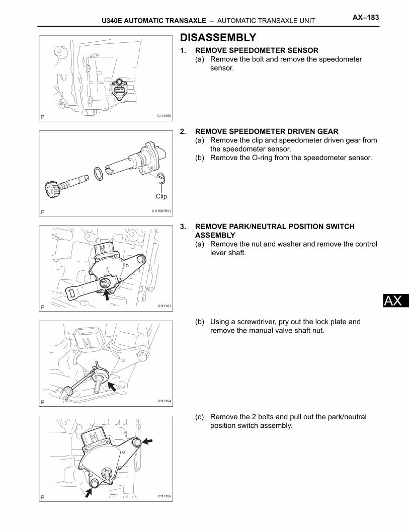
U340E AUTOMATIC TRANSAXLE – AUTOMATIC TRANSAXLE UNIT AX–183
X
ADISASSEMBLY1. REMOVE SPEEDOMETER SENSOR
(a) Remove the bolt and remove the speedometer sensor.
2. REMOVE SPEEDOMETER DRIVEN GEAR(a) Remove the clip and speedometer driven gear from
the speedometer sensor.(b) Remove the O-ring from the speedometer sensor.
3. REMOVE PARK/NEUTRAL POSITION SWITCH ASSEMBLY(a) Remove the nut and washer and remove the control
lever shaft.
(b) Using a screwdriver, pry out the lock plate and remove the manual valve shaft nut.
(c) Remove the 2 bolts and pull out the park/neutral position switch assembly.
C121660
Clip
C117097E01
C117101
C117104
C117106
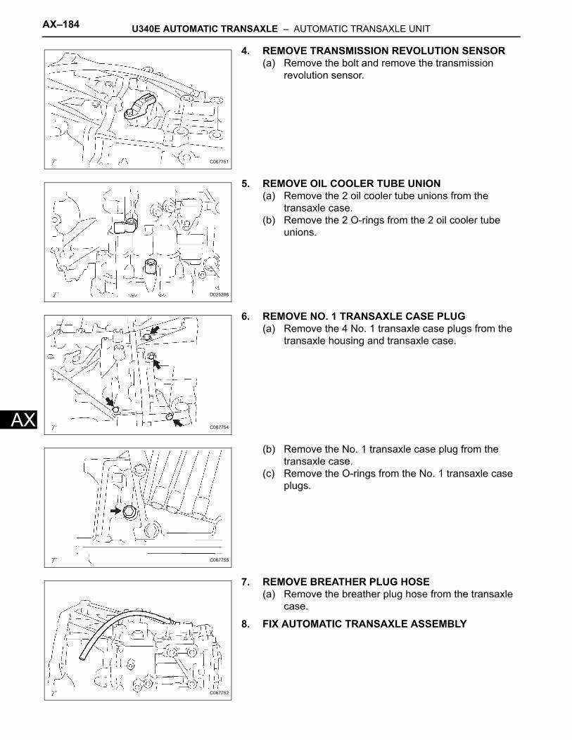
AX–184 U340E AUTOMATIC TRANSAXLE – AUTOMATIC TRANSAXLE UNIT
AX
4. REMOVE TRANSMISSION REVOLUTION SENSOR(a) Remove the bolt and remove the transmission
revolution sensor.
5. REMOVE OIL COOLER TUBE UNION(a) Remove the 2 oil cooler tube unions from the
transaxle case.(b) Remove the 2 O-rings from the 2 oil cooler tube
unions.
6. REMOVE NO. 1 TRANSAXLE CASE PLUG(a) Remove the 4 No. 1 transaxle case plugs from the
transaxle housing and transaxle case.
(b) Remove the No. 1 transaxle case plug from the transaxle case.
(c) Remove the O-rings from the No. 1 transaxle case plugs.
7. REMOVE BREATHER PLUG HOSE(a) Remove the breather plug hose from the transaxle
case.
8. FIX AUTOMATIC TRANSAXLE ASSEMBLY
C067751
D025286
C067754
C067755
C067752
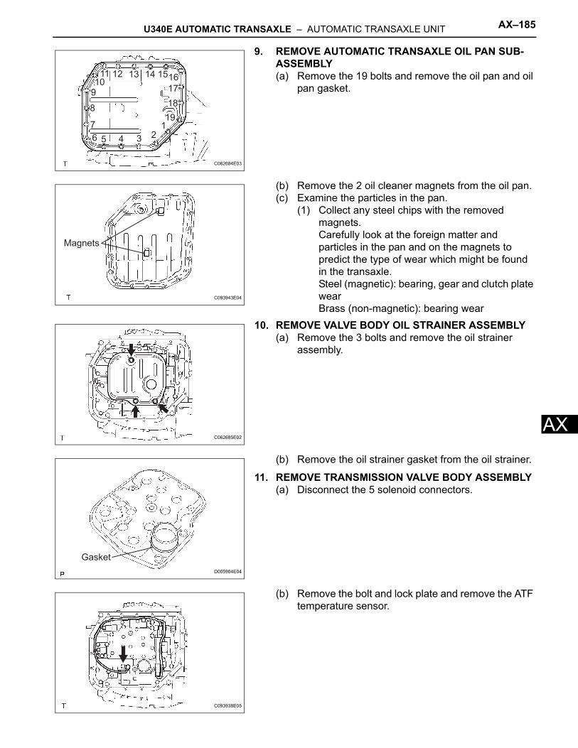
U340E AUTOMATIC TRANSAXLE – AUTOMATIC TRANSAXLE UNIT AX–185
X
A9. REMOVE AUTOMATIC TRANSAXLE OIL PAN SUB-ASSEMBLY(a) Remove the 19 bolts and remove the oil pan and oil
pan gasket.
(b) Remove the 2 oil cleaner magnets from the oil pan.(c) Examine the particles in the pan.
(1) Collect any steel chips with the removed magnets.Carefully look at the foreign matter and particles in the pan and on the magnets to predict the type of wear which might be found in the transaxle.Steel (magnetic): bearing, gear and clutch plate wearBrass (non-magnetic): bearing wear
10. REMOVE VALVE BODY OIL STRAINER ASSEMBLY(a) Remove the 3 bolts and remove the oil strainer
assembly.
(b) Remove the oil strainer gasket from the oil strainer.
11. REMOVE TRANSMISSION VALVE BODY ASSEMBLY(a) Disconnect the 5 solenoid connectors.
(b) Remove the bolt and lock plate and remove the ATF temperature sensor.
123456
7
8
910
11 12 13 14 1516
17
18
19
C062684E03
Magnets
C093943E04
C062685E02
Gasket
D005904E04
C093938E05
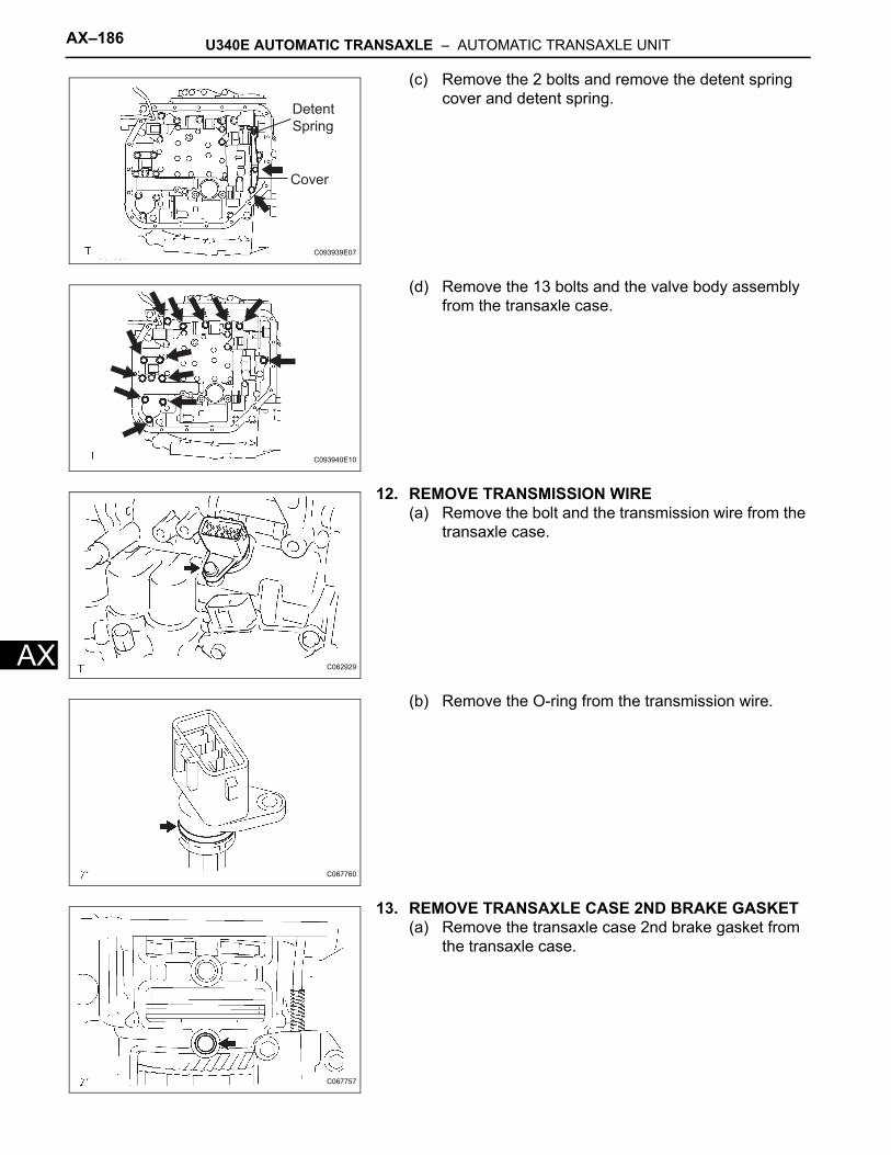
AX–186 U340E AUTOMATIC TRANSAXLE – AUTOMATIC TRANSAXLE UNIT
AX
(c) Remove the 2 bolts and remove the detent spring cover and detent spring.
(d) Remove the 13 bolts and the valve body assembly from the transaxle case.
12. REMOVE TRANSMISSION WIRE(a) Remove the bolt and the transmission wire from the
transaxle case.
(b) Remove the O-ring from the transmission wire.
13. REMOVE TRANSAXLE CASE 2ND BRAKE GASKET(a) Remove the transaxle case 2nd brake gasket from
the transaxle case.
Detent
Spring
Cover
C093939E07
C093940E10
C062929
C067760
C067757
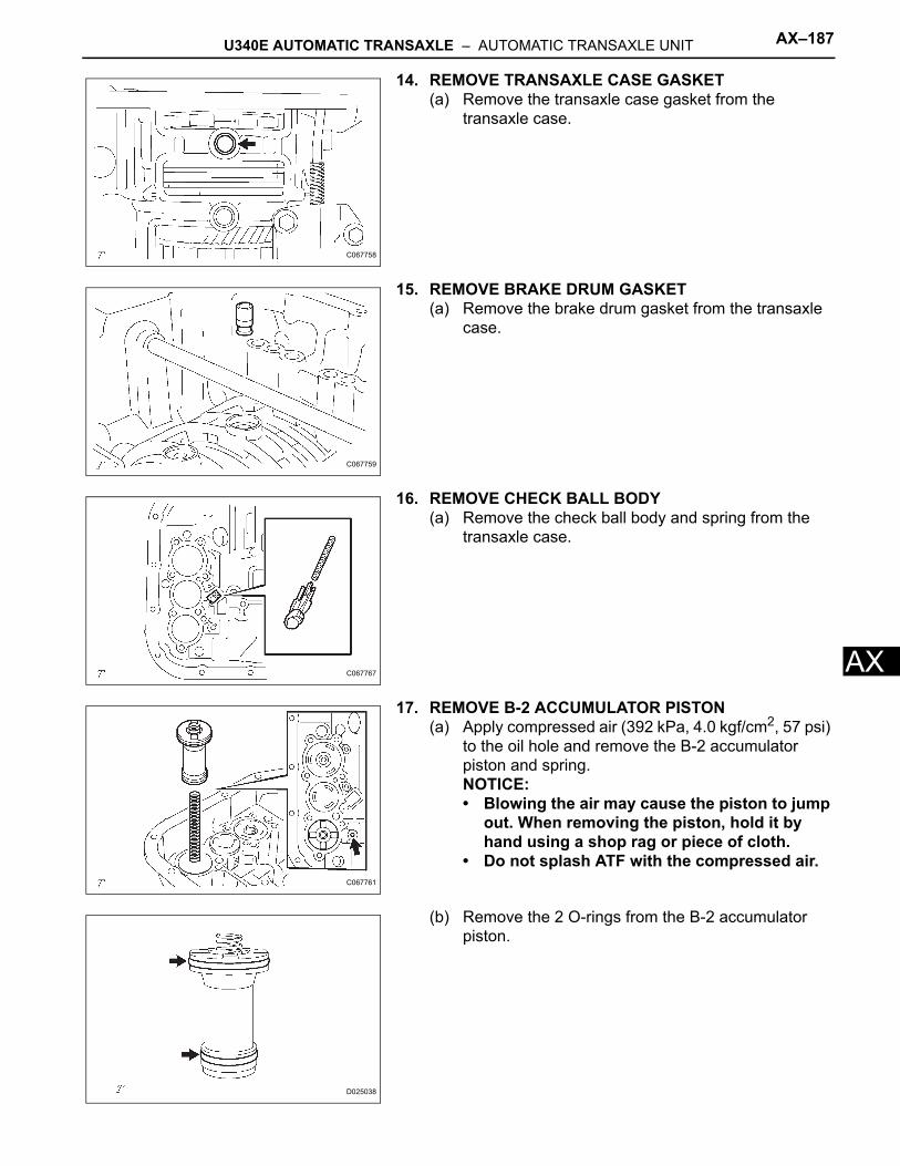
U340E AUTOMATIC TRANSAXLE – AUTOMATIC TRANSAXLE UNIT AX–187
X
A14. REMOVE TRANSAXLE CASE GASKET(a) Remove the transaxle case gasket from the
transaxle case.
15. REMOVE BRAKE DRUM GASKET(a) Remove the brake drum gasket from the transaxle
case.
16. REMOVE CHECK BALL BODY(a) Remove the check ball body and spring from the
transaxle case.
17. REMOVE B-2 ACCUMULATOR PISTON(a) Apply compressed air (392 kPa, 4.0 kgf/cm2, 57 psi)
to the oil hole and remove the B-2 accumulator piston and spring.NOTICE:• Blowing the air may cause the piston to jump
out. When removing the piston, hold it by hand using a shop rag or piece of cloth.
• Do not splash ATF with the compressed air.
(b) Remove the 2 O-rings from the B-2 accumulator piston.
C067758
C067759
C067767
C067761
D025038
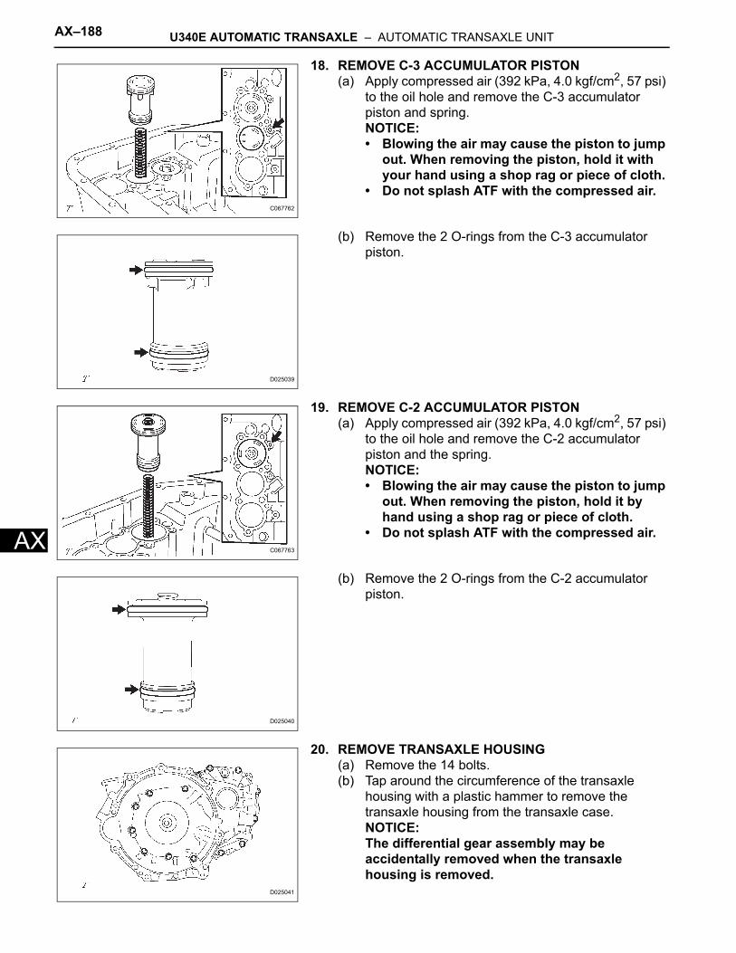
AX–188 U340E AUTOMATIC TRANSAXLE – AUTOMATIC TRANSAXLE UNIT
AX
18. REMOVE C-3 ACCUMULATOR PISTON(a) Apply compressed air (392 kPa, 4.0 kgf/cm2, 57 psi)
to the oil hole and remove the C-3 accumulator piston and spring.NOTICE:• Blowing the air may cause the piston to jump
out. When removing the piston, hold it with your hand using a shop rag or piece of cloth.
• Do not splash ATF with the compressed air.
(b) Remove the 2 O-rings from the C-3 accumulator piston.
19. REMOVE C-2 ACCUMULATOR PISTON(a) Apply compressed air (392 kPa, 4.0 kgf/cm2, 57 psi)
to the oil hole and remove the C-2 accumulator piston and the spring.NOTICE:• Blowing the air may cause the piston to jump
out. When removing the piston, hold it by hand using a shop rag or piece of cloth.
• Do not splash ATF with the compressed air.
(b) Remove the 2 O-rings from the C-2 accumulator piston.
20. REMOVE TRANSAXLE HOUSING(a) Remove the 14 bolts.(b) Tap around the circumference of the transaxle
housing with a plastic hammer to remove the transaxle housing from the transaxle case.NOTICE:The differential gear assembly may be accidentally removed when the transaxle housing is removed.
C067762
D025039
C067763
D025040
D025041
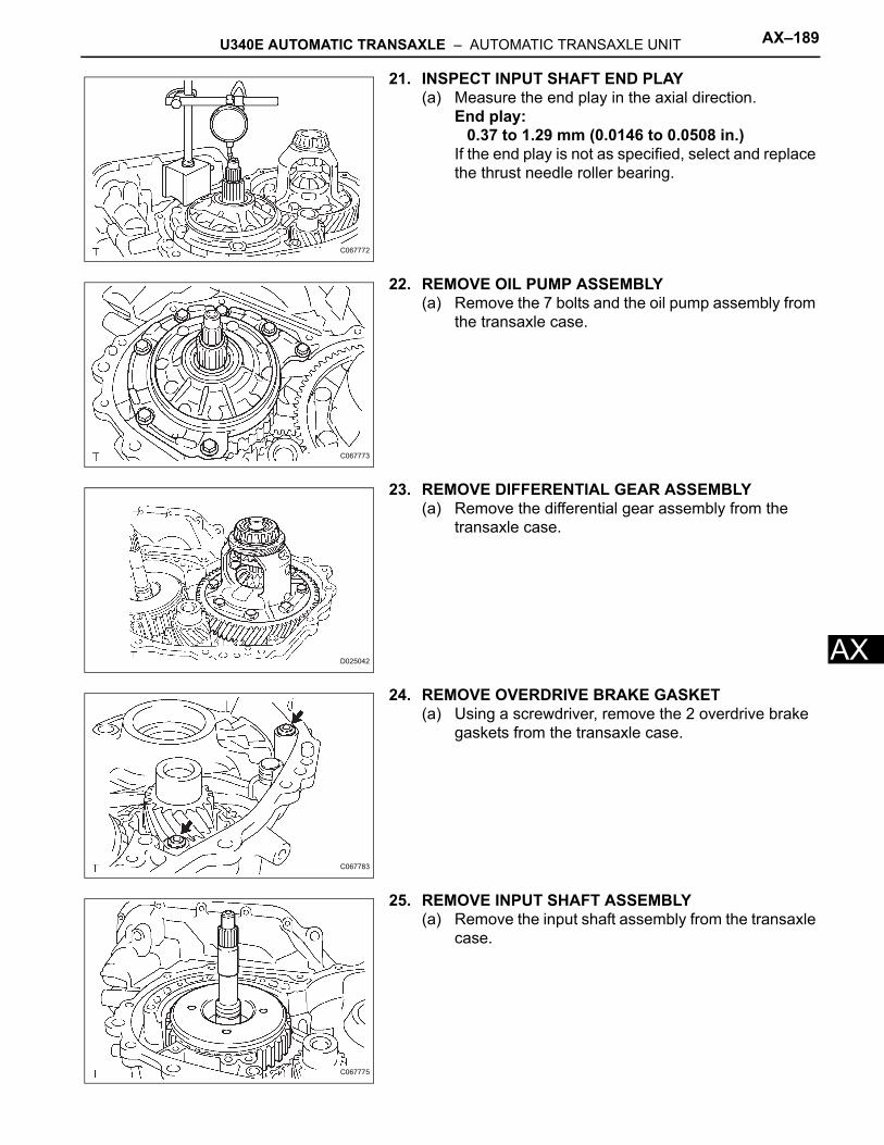
U340E AUTOMATIC TRANSAXLE – AUTOMATIC TRANSAXLE UNIT AX–189
X
A21. INSPECT INPUT SHAFT END PLAY(a) Measure the end play in the axial direction.
End play:0.37 to 1.29 mm (0.0146 to 0.0508 in.)
If the end play is not as specified, select and replace the thrust needle roller bearing.
22. REMOVE OIL PUMP ASSEMBLY(a) Remove the 7 bolts and the oil pump assembly from
the transaxle case.
23. REMOVE DIFFERENTIAL GEAR ASSEMBLY(a) Remove the differential gear assembly from the
transaxle case.
24. REMOVE OVERDRIVE BRAKE GASKET(a) Using a screwdriver, remove the 2 overdrive brake
gaskets from the transaxle case.
25. REMOVE INPUT SHAFT ASSEMBLY(a) Remove the input shaft assembly from the transaxle
case.
C067772
C067773
D025042
C067783
C067775
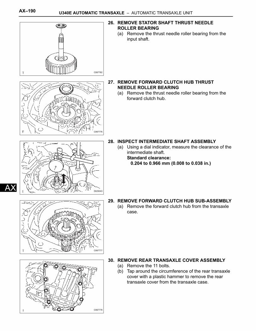
AX–190 U340E AUTOMATIC TRANSAXLE – AUTOMATIC TRANSAXLE UNIT
AX
26. REMOVE STATOR SHAFT THRUST NEEDLE ROLLER BEARING(a) Remove the thrust needle roller bearing from the
input shaft.
27. REMOVE FORWARD CLUTCH HUB THRUST NEEDLE ROLLER BEARING(a) Remove the thrust needle roller bearing from the
forward clutch hub.
28. INSPECT INTERMEDIATE SHAFT ASSEMBLY(a) Using a dial indicator, measure the clearance of the
intermediate shaft.Standard clearance:
0.204 to 0.966 mm (0.008 to 0.038 in.)
29. REMOVE FORWARD CLUTCH HUB SUB-ASSEMBLY(a) Remove the forward clutch hub from the transaxle
case.
30. REMOVE REAR TRANSAXLE COVER ASSEMBLY(a) Remove the 11 bolts.(b) Tap around the circumference of the rear transaxle
cover with a plastic hammer to remove the rear transaxle cover from the transaxle case.
C067782
C067776
D025043
C067777
C067778
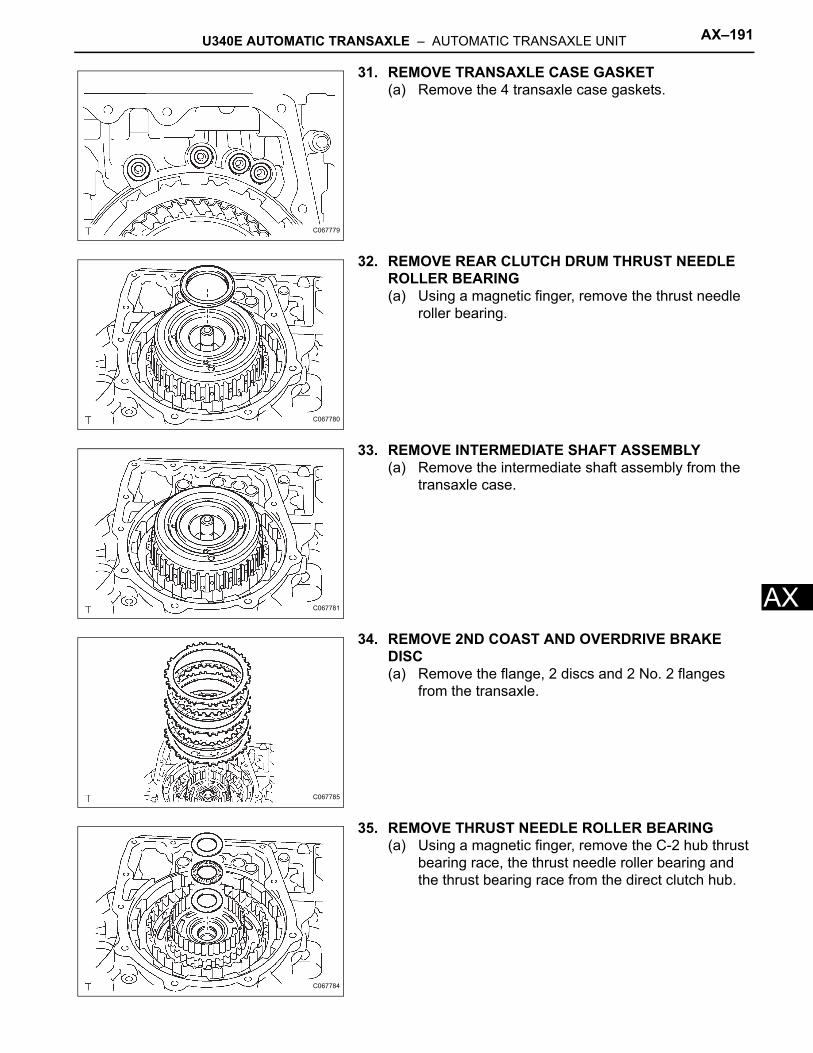
U340E AUTOMATIC TRANSAXLE – AUTOMATIC TRANSAXLE UNIT AX–191
X
A31. REMOVE TRANSAXLE CASE GASKET(a) Remove the 4 transaxle case gaskets.
32. REMOVE REAR CLUTCH DRUM THRUST NEEDLE ROLLER BEARING(a) Using a magnetic finger, remove the thrust needle
roller bearing.
33. REMOVE INTERMEDIATE SHAFT ASSEMBLY(a) Remove the intermediate shaft assembly from the
transaxle case.
34. REMOVE 2ND COAST AND OVERDRIVE BRAKE DISC(a) Remove the flange, 2 discs and 2 No. 2 flanges
from the transaxle.
35. REMOVE THRUST NEEDLE ROLLER BEARING(a) Using a magnetic finger, remove the C-2 hub thrust
bearing race, the thrust needle roller bearing and the thrust bearing race from the direct clutch hub.
C067779
C067780
C067781
C067785
C067784
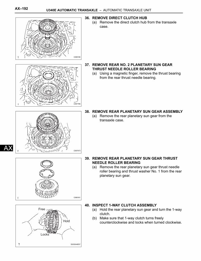
AX–192 U340E AUTOMATIC TRANSAXLE – AUTOMATIC TRANSAXLE UNIT
AX
36. REMOVE DIRECT CLUTCH HUB(a) Remove the direct clutch hub from the transaxle
case.
37. REMOVE REAR NO. 2 PLANETARY SUN GEAR THRUST NEEDLE ROLLER BEARING(a) Using a magnetic finger, remove the thrust bearing
from the rear thrust needle bearing.
38. REMOVE REAR PLANETARY SUN GEAR ASSEMBLY(a) Remove the rear planetary sun gear from the
transaxle case.
39. REMOVE REAR PLANETARY SUN GEAR THRUST NEEDLE ROLLER BEARING(a) Remove the rear planetary sun gear thrust needle
roller bearing and thrust washer No. 1 from the rear planetary sun gear.
40. INSPECT 1-WAY CLUTCH ASSEMBLY(a) Hold the rear planetary sun gear and turn the 1-way
clutch. (b) Make sure that 1-way clutch turns freely
counterclockwise and locks when turned clockwise.
C068196
C067786
C067973
C068161
Hold
Locks
Free
D025044E07
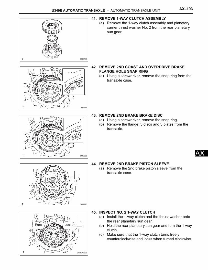
U340E AUTOMATIC TRANSAXLE – AUTOMATIC TRANSAXLE UNIT AX–193
X
A41. REMOVE 1-WAY CLUTCH ASSEMBLY(a) Remove the 1-way clutch assembly and planetary
carrier thrust washer No. 2 from the rear planetary sun gear.
42. REMOVE 2ND COAST AND OVERDRIVE BRAKE FLANGE HOLE SNAP RING(a) Using a screwdriver, remove the snap ring from the
transaxle case.
43. REMOVE 2ND BRAKE BRAKE DISC(a) Using a screwdriver, remove the snap ring.(b) Remove the flange, 3 discs and 3 plates from the
transaxle.
44. REMOVE 2ND BRAKE PISTON SLEEVE(a) Remove the 2nd brake piston sleeve from the
transaxle case.
45. INSPECT NO. 2 1-WAY CLUTCH(a) Install the 1-way clutch and the thrust washer onto
the rear planetary sun gear.(b) Hold the rear planetary sun gear and turn the 1-way
clutch. (c) Make sure that the 1-way clutch turns freely
counterclockwise and locks when turned clockwise.
C068163
C067971
C067969
C067970
Free Locks
D025045E06
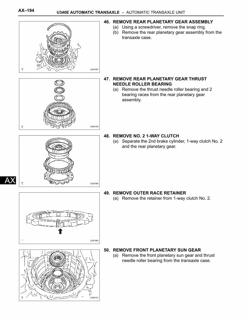
AX–194 U340E AUTOMATIC TRANSAXLE – AUTOMATIC TRANSAXLE UNIT
AX
46. REMOVE REAR PLANETARY GEAR ASSEMBLY(a) Using a screwdriver, remove the snap ring.(b) Remove the rear planetary gear assembly from the
transaxle case.
47. REMOVE REAR PLANETARY GEAR THRUST NEEDLE ROLLER BEARING(a) Remove the thrust needle roller bearing and 2
bearing races from the rear planetary gear assembly.
48. REMOVE NO. 2 1-WAY CLUTCH(a) Separate the 2nd brake cylinder, 1-way clutch No. 2
and the rear planetary gear.
49. REMOVE OUTER RACE RETAINER(a) Remove the retainer from 1-way clutch No. 2.
50. REMOVE FRONT PLANETARY SUN GEAR(a) Remove the front planetary sun gear and thrust
needle roller bearing from the transaxle case.
C067967
C068159
C067966
C067965
C068157
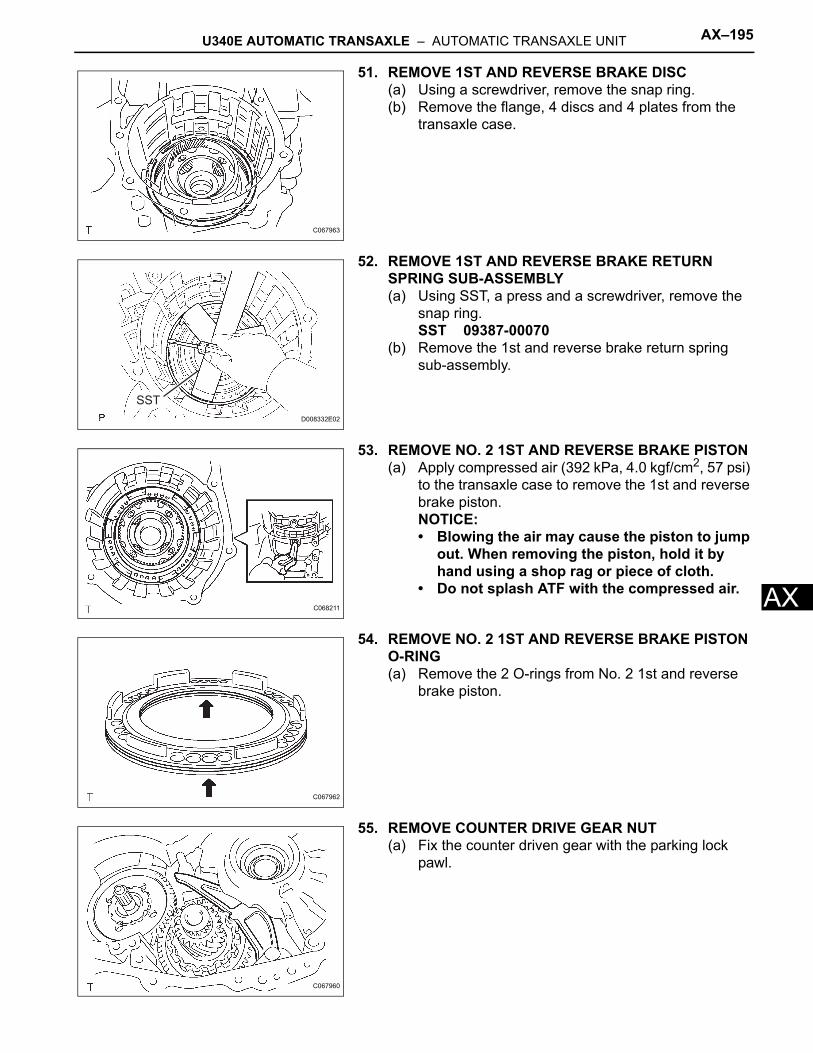
U340E AUTOMATIC TRANSAXLE – AUTOMATIC TRANSAXLE UNIT AX–195
X
A51. REMOVE 1ST AND REVERSE BRAKE DISC(a) Using a screwdriver, remove the snap ring.(b) Remove the flange, 4 discs and 4 plates from the
transaxle case.
52. REMOVE 1ST AND REVERSE BRAKE RETURN SPRING SUB-ASSEMBLY(a) Using SST, a press and a screwdriver, remove the
snap ring.SST 09387-00070
(b) Remove the 1st and reverse brake return spring sub-assembly.
53. REMOVE NO. 2 1ST AND REVERSE BRAKE PISTON(a) Apply compressed air (392 kPa, 4.0 kgf/cm2, 57 psi)
to the transaxle case to remove the 1st and reverse brake piston.NOTICE:• Blowing the air may cause the piston to jump
out. When removing the piston, hold it by hand using a shop rag or piece of cloth.
• Do not splash ATF with the compressed air.
54. REMOVE NO. 2 1ST AND REVERSE BRAKE PISTON O-RING(a) Remove the 2 O-rings from No. 2 1st and reverse
brake piston.
55. REMOVE COUNTER DRIVE GEAR NUT(a) Fix the counter driven gear with the parking lock
pawl.
C067963
SST
D008332E02
C068211
C067962
C067960
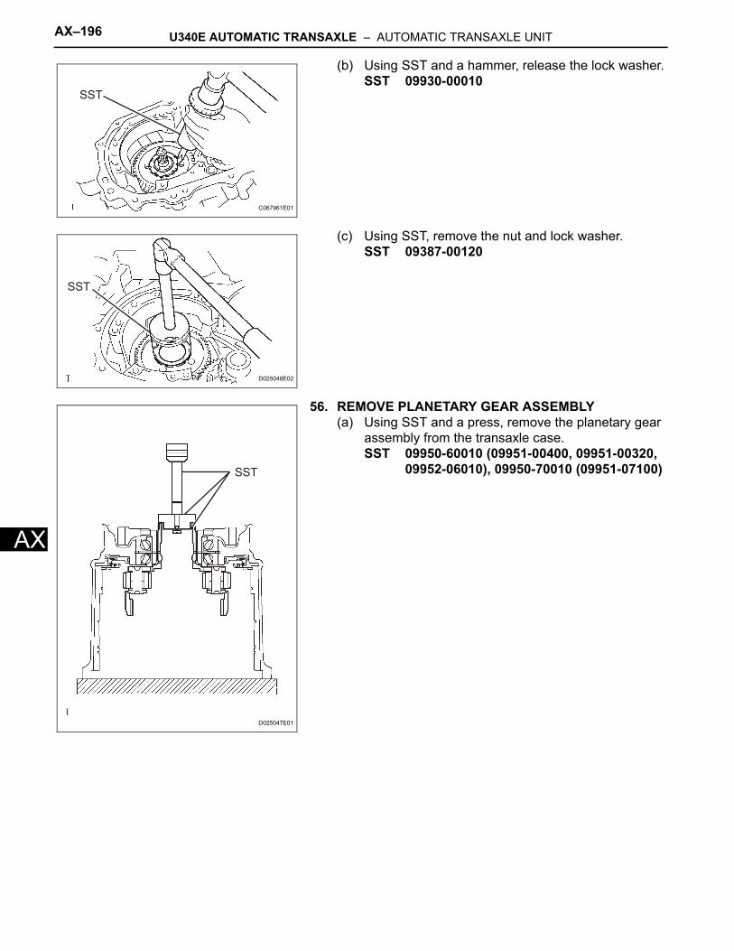
AX–196 U340E AUTOMATIC TRANSAXLE – AUTOMATIC TRANSAXLE UNIT
AX
(b) Using SST and a hammer, release the lock washer.SST 09930-00010
(c) Using SST, remove the nut and lock washer.SST 09387-00120
56. REMOVE PLANETARY GEAR ASSEMBLY(a) Using SST and a press, remove the planetary gear
assembly from the transaxle case.SST 09950-60010 (09951-00400, 09951-00320,
09952-06010), 09950-70010 (09951-07100)
SST
C067961E01
SST
D025048E02
SST
D025047E01
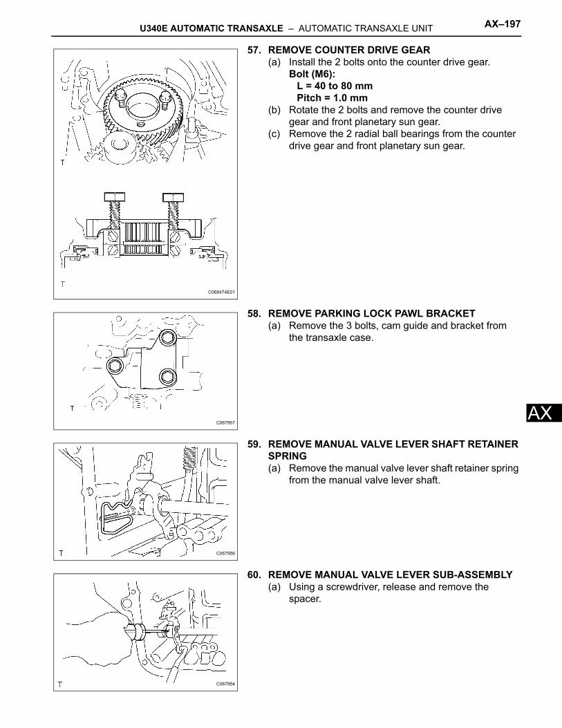
U340E AUTOMATIC TRANSAXLE – AUTOMATIC TRANSAXLE UNIT AX–197
X
A57. REMOVE COUNTER DRIVE GEAR(a) Install the 2 bolts onto the counter drive gear.
Bolt (M6):L = 40 to 80 mmPitch = 1.0 mm
(b) Rotate the 2 bolts and remove the counter drive gear and front planetary sun gear.
(c) Remove the 2 radial ball bearings from the counter drive gear and front planetary sun gear.
58. REMOVE PARKING LOCK PAWL BRACKET(a) Remove the 3 bolts, cam guide and bracket from
the transaxle case.
59. REMOVE MANUAL VALVE LEVER SHAFT RETAINER SPRING(a) Remove the manual valve lever shaft retainer spring
from the manual valve lever shaft.
60. REMOVE MANUAL VALVE LEVER SUB-ASSEMBLY(a) Using a screwdriver, release and remove the
spacer.
C068474E01
C067957
C067956
C067954
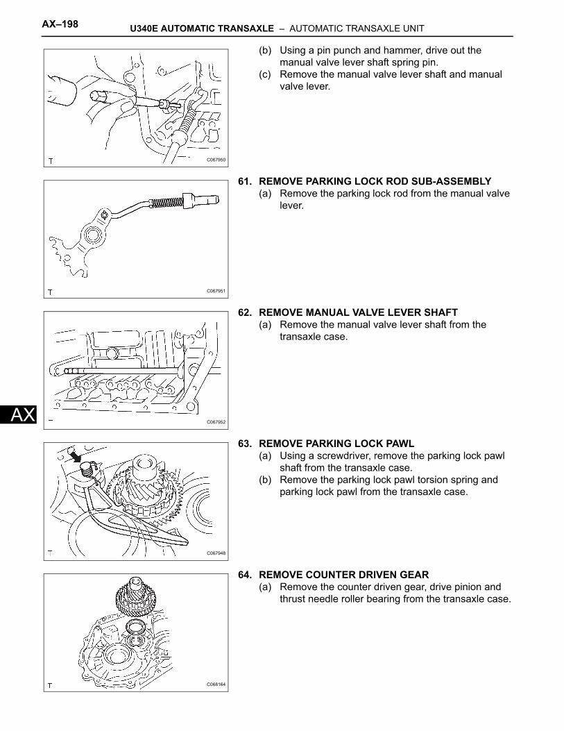
AX–198 U340E AUTOMATIC TRANSAXLE – AUTOMATIC TRANSAXLE UNIT
AX
(b) Using a pin punch and hammer, drive out the manual valve lever shaft spring pin.
(c) Remove the manual valve lever shaft and manual valve lever.
61. REMOVE PARKING LOCK ROD SUB-ASSEMBLY(a) Remove the parking lock rod from the manual valve
lever.
62. REMOVE MANUAL VALVE LEVER SHAFT(a) Remove the manual valve lever shaft from the
transaxle case.
63. REMOVE PARKING LOCK PAWL(a) Using a screwdriver, remove the parking lock pawl
shaft from the transaxle case.(b) Remove the parking lock pawl torsion spring and
parking lock pawl from the transaxle case.
64. REMOVE COUNTER DRIVEN GEAR(a) Remove the counter driven gear, drive pinion and
thrust needle roller bearing from the transaxle case.
C067950
C067951
C067952
C067948
C068164
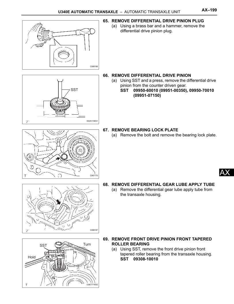
U340E AUTOMATIC TRANSAXLE – AUTOMATIC TRANSAXLE UNIT AX–199
X
A65. REMOVE DIFFERENTIAL DRIVE PINION PLUG(a) Using a brass bar and a hammer, remove the
differential drive pinion plug.
66. REMOVE DIFFERENTIAL DRIVE PINION(a) Using SST and a press, remove the differential drive
pinion from the counter driven gear.SST 09950-60010 (09951-00350), 09950-70010
(09951-07150)
67. REMOVE BEARING LOCK PLATE(a) Remove the bolt and remove the bearing lock plate.
68. REMOVE DIFFERENTIAL GEAR LUBE APPLY TUBE(a) Remove the differential gear lube apply tube from
the transaxle housing.
69. REMOVE FRONT DRIVE PINION FRONT TAPERED ROLLER BEARING(a) Using SST, remove the front drive pinion front
tapered roller bearing from the transaxle housing.SST 09308-10010
C068188
SST
D025174E01
C067770
C068187
Turn
Hold
SST
C067771E02
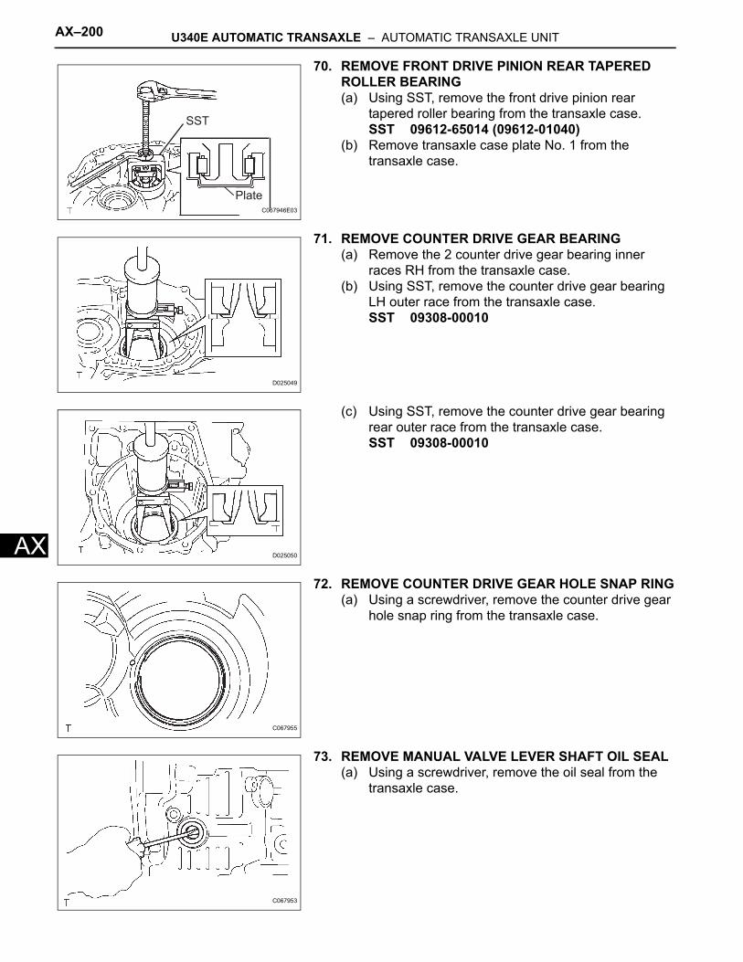
AX–200 U340E AUTOMATIC TRANSAXLE – AUTOMATIC TRANSAXLE UNIT
AX
70. REMOVE FRONT DRIVE PINION REAR TAPERED ROLLER BEARING(a) Using SST, remove the front drive pinion rear
tapered roller bearing from the transaxle case.SST 09612-65014 (09612-01040)
(b) Remove transaxle case plate No. 1 from the transaxle case.
71. REMOVE COUNTER DRIVE GEAR BEARING(a) Remove the 2 counter drive gear bearing inner
races RH from the transaxle case.(b) Using SST, remove the counter drive gear bearing
LH outer race from the transaxle case.SST 09308-00010
(c) Using SST, remove the counter drive gear bearing rear outer race from the transaxle case.SST 09308-00010
72. REMOVE COUNTER DRIVE GEAR HOLE SNAP RING(a) Using a screwdriver, remove the counter drive gear
hole snap ring from the transaxle case.
73. REMOVE MANUAL VALVE LEVER SHAFT OIL SEAL(a) Using a screwdriver, remove the oil seal from the
transaxle case.
SST
PlateC067946E03
D025049
D025050
C067955
C067953
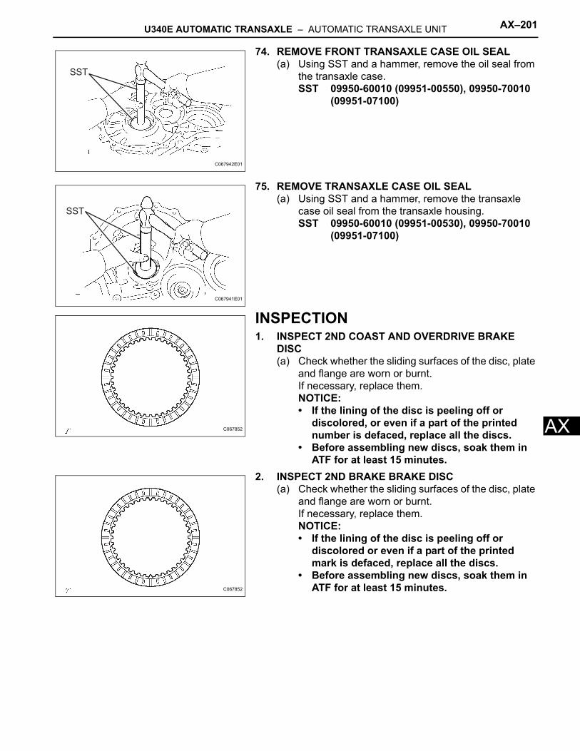
U340E AUTOMATIC TRANSAXLE – AUTOMATIC TRANSAXLE UNIT AX–201
X
A74. REMOVE FRONT TRANSAXLE CASE OIL SEAL(a) Using SST and a hammer, remove the oil seal from
the transaxle case.SST 09950-60010 (09951-00550), 09950-70010
(09951-07100)
75. REMOVE TRANSAXLE CASE OIL SEAL(a) Using SST and a hammer, remove the transaxle
case oil seal from the transaxle housing.SST 09950-60010 (09951-00530), 09950-70010
(09951-07100)
INSPECTION1. INSPECT 2ND COAST AND OVERDRIVE BRAKE
DISC(a) Check whether the sliding surfaces of the disc, plate
and flange are worn or burnt.If necessary, replace them.NOTICE:• If the lining of the disc is peeling off or
discolored, or even if a part of the printed number is defaced, replace all the discs.
• Before assembling new discs, soak them in ATF for at least 15 minutes.
2. INSPECT 2ND BRAKE BRAKE DISC(a) Check whether the sliding surfaces of the disc, plate
and flange are worn or burnt.If necessary, replace them.NOTICE:• If the lining of the disc is peeling off or
discolored or even if a part of the printed mark is defaced, replace all the discs.
• Before assembling new discs, soak them in ATF for at least 15 minutes.
SST
C067942E01
SST
C067941E01
C067852
C067852
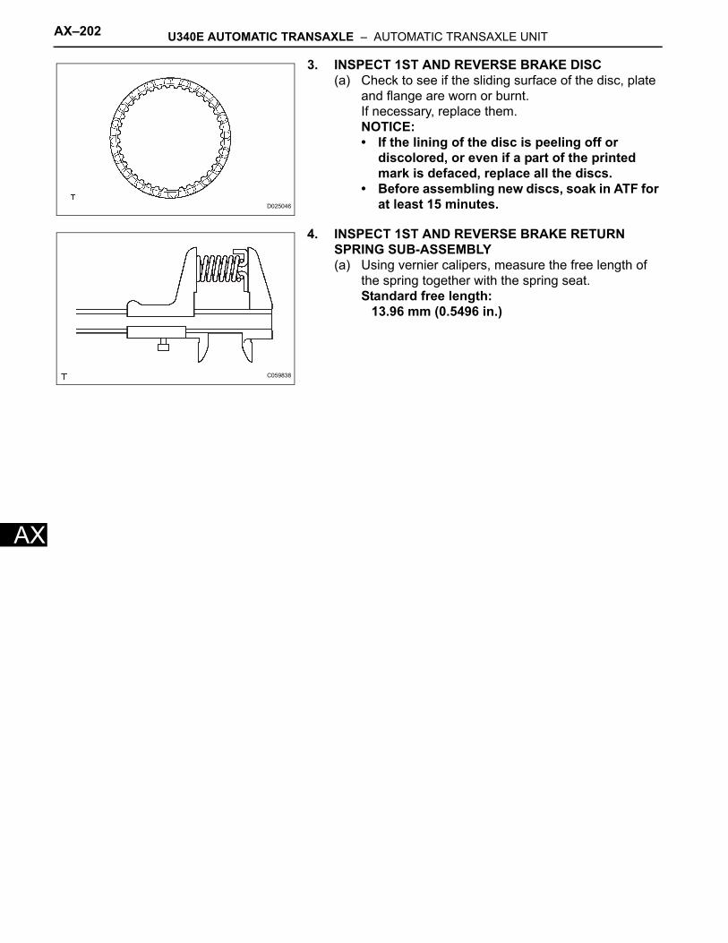
AX–202 U340E AUTOMATIC TRANSAXLE – AUTOMATIC TRANSAXLE UNIT
AX
3. INSPECT 1ST AND REVERSE BRAKE DISC(a) Check to see if the sliding surface of the disc, plate
and flange are worn or burnt.If necessary, replace them.NOTICE:• If the lining of the disc is peeling off or
discolored, or even if a part of the printed mark is defaced, replace all the discs.
• Before assembling new discs, soak in ATF for at least 15 minutes.
4. INSPECT 1ST AND REVERSE BRAKE RETURN SPRING SUB-ASSEMBLY(a) Using vernier calipers, measure the free length of
the spring together with the spring seat.Standard free length:
13.96 mm (0.5496 in.)
D025046
C059838
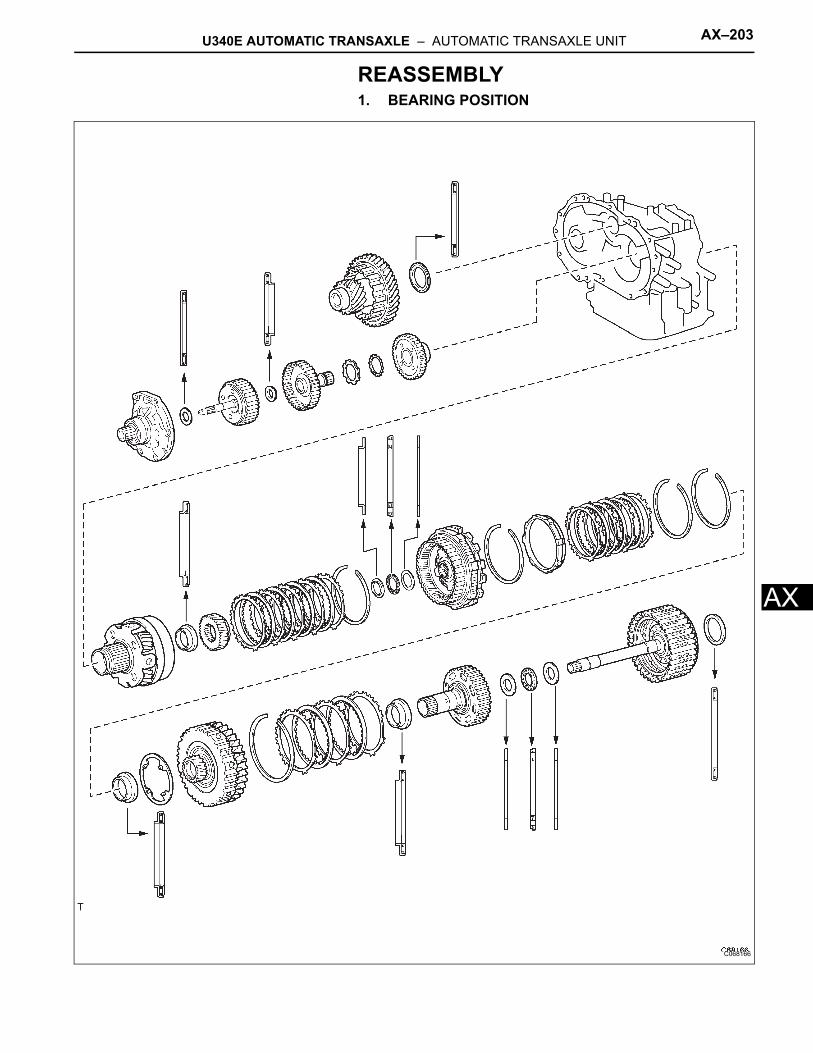
U340E AUTOMATIC TRANSAXLE – AUTOMATIC TRANSAXLE UNIT AX–203
X
AREASSEMBLY1. BEARING POSITION
C068166
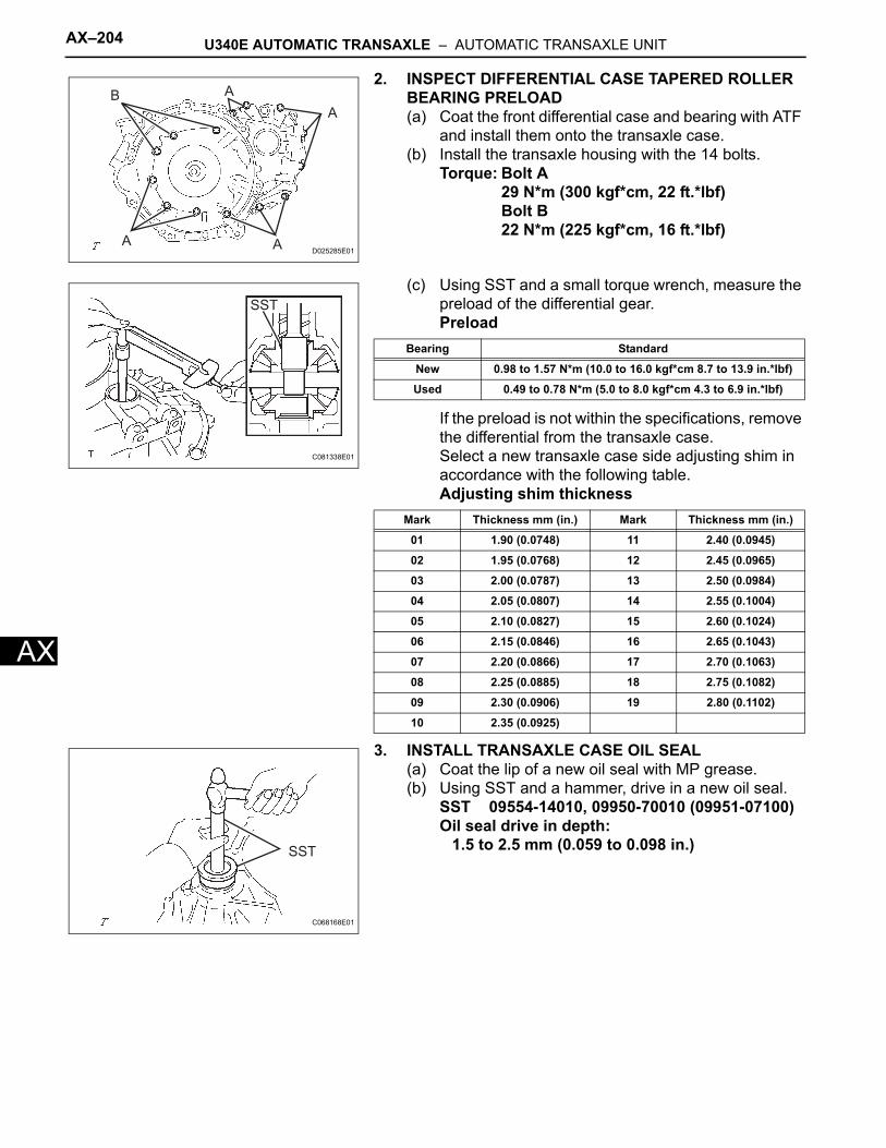
AX–204 U340E AUTOMATIC TRANSAXLE – AUTOMATIC TRANSAXLE UNIT
AX
2. INSPECT DIFFERENTIAL CASE TAPERED ROLLER BEARING PRELOAD(a) Coat the front differential case and bearing with ATF
and install them onto the transaxle case.(b) Install the transaxle housing with the 14 bolts.
Torque: Bolt A29 N*m (300 kgf*cm, 22 ft.*lbf)Bolt B22 N*m (225 kgf*cm, 16 ft.*lbf)
(c) Using SST and a small torque wrench, measure the preload of the differential gear.Preload
If the preload is not within the specifications, remove the differential from the transaxle case. Select a new transaxle case side adjusting shim in accordance with the following table.Adjusting shim thickness
3. INSTALL TRANSAXLE CASE OIL SEAL(a) Coat the lip of a new oil seal with MP grease.(b) Using SST and a hammer, drive in a new oil seal.
SST 09554-14010, 09950-70010 (09951-07100)Oil seal drive in depth:
1.5 to 2.5 mm (0.059 to 0.098 in.)
AB
A
AAD025285E01
SST
C081338E01
Bearing Standard
New 0.98 to 1.57 N*m (10.0 to 16.0 kgf*cm 8.7 to 13.9 in.*lbf)
Used 0.49 to 0.78 N*m (5.0 to 8.0 kgf*cm 4.3 to 6.9 in.*lbf)
Mark Thickness mm (in.) Mark Thickness mm (in.)
01 1.90 (0.0748) 11 2.40 (0.0945)
02 1.95 (0.0768) 12 2.45 (0.0965)
03 2.00 (0.0787) 13 2.50 (0.0984)
04 2.05 (0.0807) 14 2.55 (0.1004)
05 2.10 (0.0827) 15 2.60 (0.1024)
06 2.15 (0.0846) 16 2.65 (0.1043)
07 2.20 (0.0866) 17 2.70 (0.1063)
08 2.25 (0.0885) 18 2.75 (0.1082)
09 2.30 (0.0906) 19 2.80 (0.1102)
10 2.35 (0.0925)
SST
C068168E01
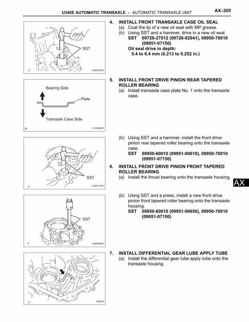
U340E AUTOMATIC TRANSAXLE – AUTOMATIC TRANSAXLE UNIT AX–205
X
A4. INSTALL FRONT TRANSAXLE CASE OIL SEAL(a) Coat the lip of a new oil seal with MP grease.(b) Using SST and a hammer, drive in a new oil seal.
SST 09726-27012 (09726-02041), 09950-70010 (09951-07150)
Oil seal drive in depth:5.4 to 6.4 mm (0.213 to 0.252 in.)
5. INSTALL FRONT DRIVE PINION REAR TAPERED ROLLER BEARING(a) Install transaxle case plate No. 1 onto the transaxle
case.
(b) Using SST and a hammer, install the front drive pinion rear tapered roller bearing onto the transaxle case.SST 09950-60010 (09951-00610), 09950-70010
(09951-07150)6. INSTALL FRONT DRIVE PINION FRONT TAPERED
ROLLER BEARING(a) Install the thrust bearing onto the transaxle housing.
(b) Using SST and a press, install a new front drive pinion front tapered roller bearing onto the transaxle housing.SST 09950-60010 (09951-00650), 09950-70010
(09951-07150)
7. INSTALL DIFFERENTIAL GEAR LUBE APPLY TUBE(a) Install the differential gear lube apply tube onto the
transaxle housing.
SST
C068167E01
Bearing Side
Transaxle Case Side
Plate
C125250E01
SST
C068171E01
SST
C068209E01
C068187
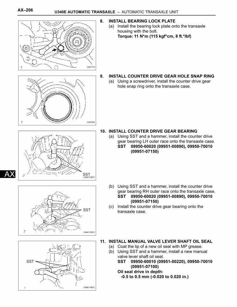
AX–206 U340E AUTOMATIC TRANSAXLE – AUTOMATIC TRANSAXLE UNIT
AX
8. INSTALL BEARING LOCK PLATE(a) Install the bearing lock plate onto the transaxle
housing with the bolt.Torque: 11 N*m (115 kgf*cm, 8 ft.*lbf)
9. INSTALL COUNTER DRIVE GEAR HOLE SNAP RING(a) Using a screwdriver, install the counter drive gear
hole snap ring onto the transaxle case.
10. INSTALL COUNTER DRIVE GEAR BEARING(a) Using SST and a hammer, install the counter drive
gear bearing LH outer race onto the transaxle case.SST 09950-60020 (09951-00890), 09950-70010
(09951-07150)
(b) Using SST and a hammer, install the counter drive gear bearing RH outer race onto the transaxle case.SST 09950-60020 (09951-00890), 09950-70010
(09951-07150)(c) Install the counter drive gear bearing onto the
transaxle case.
11. INSTALL MANUAL VALVE LEVER SHAFT OIL SEAL(a) Coat the lip of a new oil seal with MP grease.(b) Using SST and a hammer, install a new manual
valve lever shaft oil seal.SST 09950-60010 (09951-00220), 09950-70010
(09951-07100)Oil seal drive in depth:
-0.5 to 0.5 mm (-0.020 to 0.020 in.)
C067770
C067955
SSTC068173E01
SST
C068172E01
SST
C068174E01
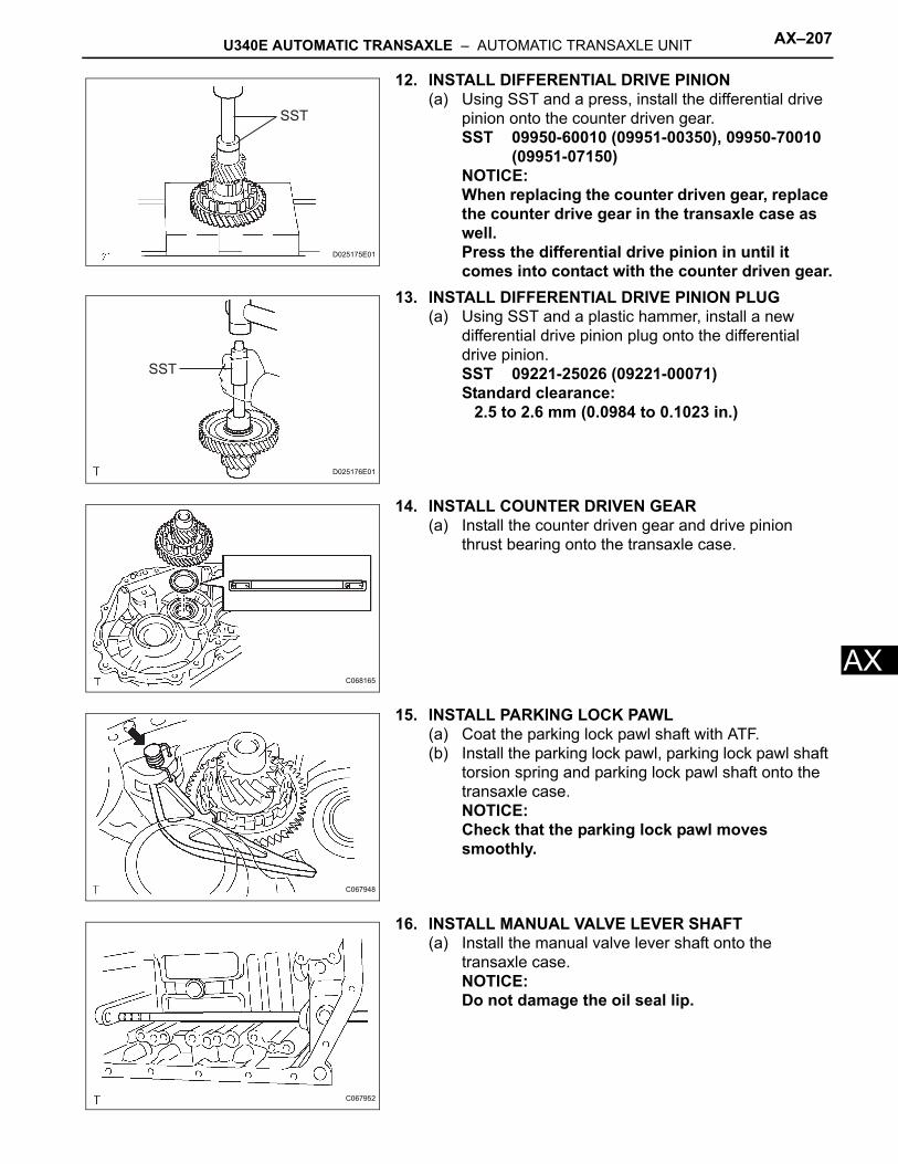
U340E AUTOMATIC TRANSAXLE – AUTOMATIC TRANSAXLE UNIT AX–207
X
A12. INSTALL DIFFERENTIAL DRIVE PINION(a) Using SST and a press, install the differential drive
pinion onto the counter driven gear. SST 09950-60010 (09951-00350), 09950-70010
(09951-07150)NOTICE:When replacing the counter driven gear, replace the counter drive gear in the transaxle case as well.Press the differential drive pinion in until it comes into contact with the counter driven gear.
13. INSTALL DIFFERENTIAL DRIVE PINION PLUG(a) Using SST and a plastic hammer, install a new
differential drive pinion plug onto the differential drive pinion.SST 09221-25026 (09221-00071)Standard clearance:
2.5 to 2.6 mm (0.0984 to 0.1023 in.)
14. INSTALL COUNTER DRIVEN GEAR(a) Install the counter driven gear and drive pinion
thrust bearing onto the transaxle case.
15. INSTALL PARKING LOCK PAWL(a) Coat the parking lock pawl shaft with ATF.(b) Install the parking lock pawl, parking lock pawl shaft
torsion spring and parking lock pawl shaft onto the transaxle case.NOTICE:Check that the parking lock pawl moves smoothly.
16. INSTALL MANUAL VALVE LEVER SHAFT(a) Install the manual valve lever shaft onto the
transaxle case.NOTICE:Do not damage the oil seal lip.
SST
D025175E01
SST
D025176E01
C068165
C067948
C067952
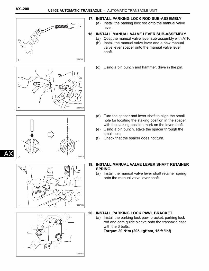
AX–208 U340E AUTOMATIC TRANSAXLE – AUTOMATIC TRANSAXLE UNIT
AX
17. INSTALL PARKING LOCK ROD SUB-ASSEMBLY(a) Install the parking lock rod onto the manual valve
lever.
18. INSTALL MANUAL VALVE LEVER SUB-ASSEMBLY(a) Coat the manual valve lever sub-assembly with ATF.(b) Install the manual valve lever and a new manual
valve lever spacer onto the manual valve lever shaft.
(c) Using a pin punch and hammer, drive in the pin.
(d) Turn the spacer and lever shaft to align the small hole for locating the staking position in the spacer with the staking position mark on the lever shaft.
(e) Using a pin punch, stake the spacer through the small hole.
(f) Check that the spacer does not turn.
19. INSTALL MANUAL VALVE LEVER SHAFT RETAINER SPRING(a) Install the manual valve lever shaft retainer spring
onto the manual valve lever shaft.
20. INSTALL PARKING LOCK PAWL BRACKET(a) Install the parking lock pawl bracket, parking lock
rod and cam guide sleeve onto the transaxle case with the 3 bolts.Torque: 20 N*m (205 kgf*cm, 15 ft.*lbf)
C067951
C067950
C068175
C067956
C067957
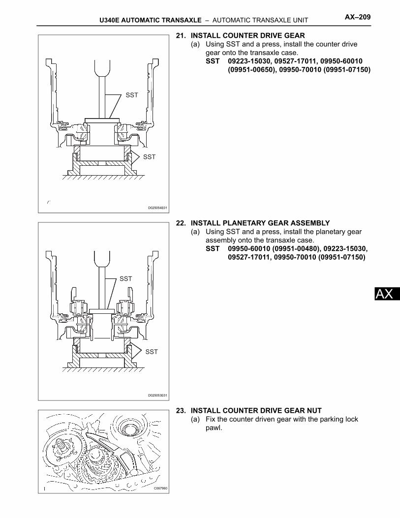
U340E AUTOMATIC TRANSAXLE – AUTOMATIC TRANSAXLE UNIT AX–209
X
A21. INSTALL COUNTER DRIVE GEAR(a) Using SST and a press, install the counter drive
gear onto the transaxle case.SST 09223-15030, 09527-17011, 09950-60010
(09951-00650), 09950-70010 (09951-07150)
22. INSTALL PLANETARY GEAR ASSEMBLY(a) Using SST and a press, install the planetary gear
assembly onto the transaxle case.SST 09950-60010 (09951-00480), 09223-15030,
09527-17011, 09950-70010 (09951-07150)
23. INSTALL COUNTER DRIVE GEAR NUT(a) Fix the counter driven gear with the parking lock
pawl.
SST
SST
D025054E01
SST
SST
D025053E01
C067960
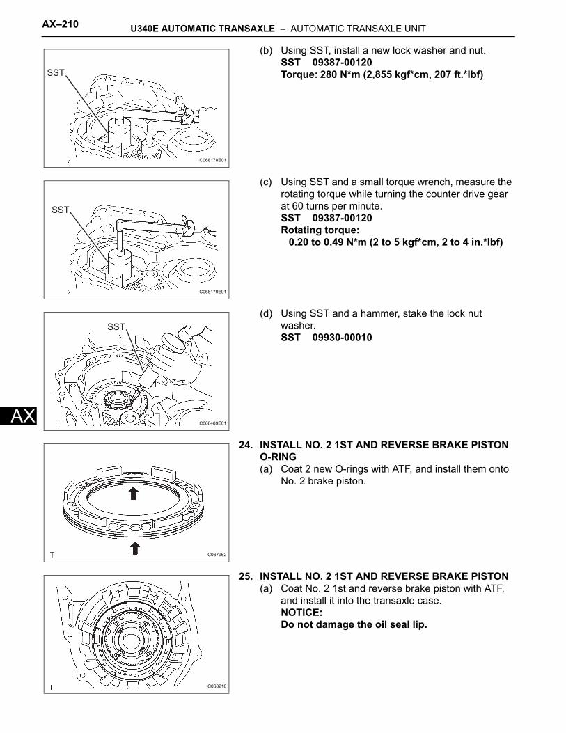
AX–210 U340E AUTOMATIC TRANSAXLE – AUTOMATIC TRANSAXLE UNIT
AX
(b) Using SST, install a new lock washer and nut.SST 09387-00120Torque: 280 N*m (2,855 kgf*cm, 207 ft.*lbf)
(c) Using SST and a small torque wrench, measure the rotating torque while turning the counter drive gear at 60 turns per minute.SST 09387-00120Rotating torque:
0.20 to 0.49 N*m (2 to 5 kgf*cm, 2 to 4 in.*lbf)
(d) Using SST and a hammer, stake the lock nut washer.SST 09930-00010
24. INSTALL NO. 2 1ST AND REVERSE BRAKE PISTON O-RING(a) Coat 2 new O-rings with ATF, and install them onto
No. 2 brake piston.
25. INSTALL NO. 2 1ST AND REVERSE BRAKE PISTON(a) Coat No. 2 1st and reverse brake piston with ATF,
and install it into the transaxle case.NOTICE:Do not damage the oil seal lip.
SST
C068178E01
SST
C068179E01
SST
C068469E01
C067962
C068210
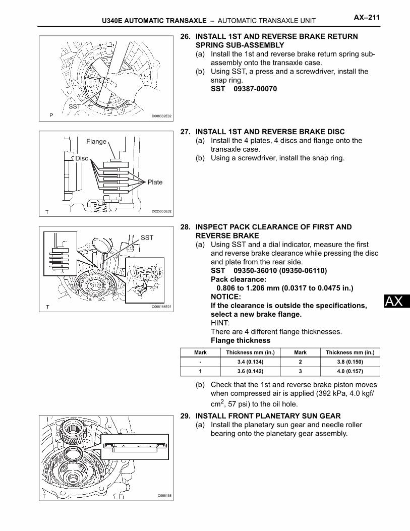
U340E AUTOMATIC TRANSAXLE – AUTOMATIC TRANSAXLE UNIT AX–211
X
A26. INSTALL 1ST AND REVERSE BRAKE RETURN SPRING SUB-ASSEMBLY(a) Install the 1st and reverse brake return spring sub-
assembly onto the transaxle case.(b) Using SST, a press and a screwdriver, install the
snap ring.SST 09387-00070
27. INSTALL 1ST AND REVERSE BRAKE DISC(a) Install the 4 plates, 4 discs and flange onto the
transaxle case.(b) Using a screwdriver, install the snap ring.
28. INSPECT PACK CLEARANCE OF FIRST AND REVERSE BRAKE(a) Using SST and a dial indicator, measure the first
and reverse brake clearance while pressing the disc and plate from the rear side.SST 09350-36010 (09350-06110)Pack clearance:
0.806 to 1.206 mm (0.0317 to 0.0475 in.)NOTICE:If the clearance is outside the specifications, select a new brake flange.HINT:There are 4 different flange thicknesses.Flange thickness
(b) Check that the 1st and reverse brake piston moves when compressed air is applied (392 kPa, 4.0 kgf/cm2, 57 psi) to the oil hole.
29. INSTALL FRONT PLANETARY SUN GEAR(a) Install the planetary sun gear and needle roller
bearing onto the planetary gear assembly.
SST
D008332E02
Disc
Plate
Flange
D025055E02
SST
C068184E01
Mark Thickness mm (in.) Mark Thickness mm (in.)
- 3.4 (0.134) 2 3.8 (0.150)
1 3.6 (0.142) 3 4.0 (0.157)
C068158
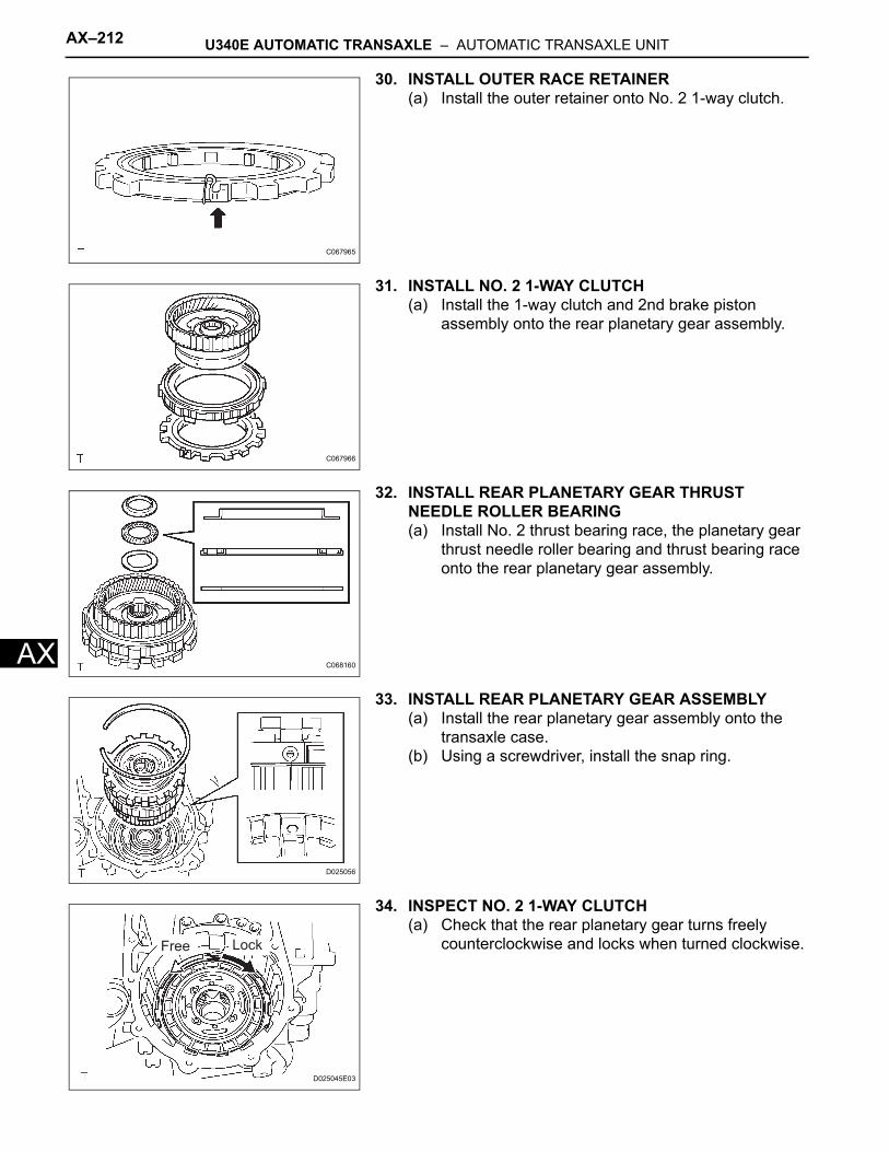
AX–212 U340E AUTOMATIC TRANSAXLE – AUTOMATIC TRANSAXLE UNIT
AX
30. INSTALL OUTER RACE RETAINER(a) Install the outer retainer onto No. 2 1-way clutch.
31. INSTALL NO. 2 1-WAY CLUTCH(a) Install the 1-way clutch and 2nd brake piston
assembly onto the rear planetary gear assembly.
32. INSTALL REAR PLANETARY GEAR THRUST NEEDLE ROLLER BEARING(a) Install No. 2 thrust bearing race, the planetary gear
thrust needle roller bearing and thrust bearing race onto the rear planetary gear assembly.
33. INSTALL REAR PLANETARY GEAR ASSEMBLY(a) Install the rear planetary gear assembly onto the
transaxle case.(b) Using a screwdriver, install the snap ring.
34. INSPECT NO. 2 1-WAY CLUTCH(a) Check that the rear planetary gear turns freely
counterclockwise and locks when turned clockwise.
C067965
C067966
C068160
D025056
Free Lock
D025045E03
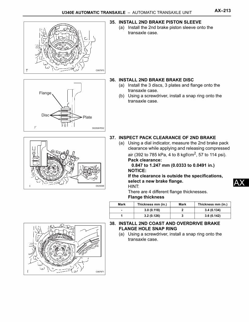
U340E AUTOMATIC TRANSAXLE – AUTOMATIC TRANSAXLE UNIT AX–213
X
A35. INSTALL 2ND BRAKE PISTON SLEEVE(a) Install the 2nd brake piston sleeve onto the
transaxle case.
36. INSTALL 2ND BRAKE BRAKE DISC(a) Install the 3 discs, 3 plates and flange onto the
transaxle case.(b) Using a screwdriver, install a snap ring onto the
transaxle case.
37. INSPECT PACK CLEARANCE OF 2ND BRAKE(a) Using a dial indicator, measure the 2nd brake pack
clearance while applying and releasing compressed air (392 to 785 kPa, 4 to 8 kgf/cm2, 57 to 114 psi).Pack clearance:
0.847 to 1.247 mm (0.0333 to 0.0491 in.)NOTICE:If the clearance is outside the specifications, select a new brake flange.HINT:There are 4 different flange thicknesses.Flange thickness
38. INSTALL 2ND COAST AND OVERDRIVE BRAKE FLANGE HOLE SNAP RING(a) Using a screwdriver, install a snap ring onto the
transaxle case.
C067970
Flange
DiscPlate
D025097E02
D025098
Mark Thickness mm (in.) Mark Thickness mm (in.)
- 3.0 (0.118) 2 3.4 (0.134)
1 3.2 (0.126) 3 3.6 (0.142)
C067971
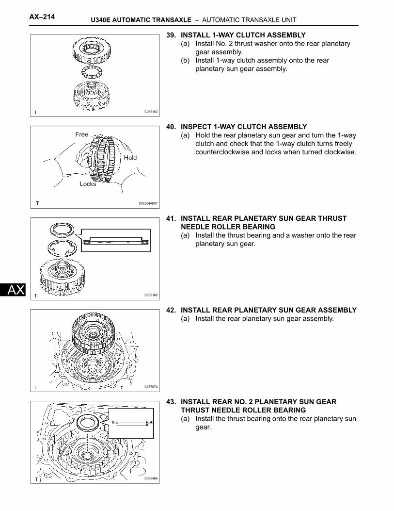
AX–214 U340E AUTOMATIC TRANSAXLE – AUTOMATIC TRANSAXLE UNIT
AX
39. INSTALL 1-WAY CLUTCH ASSEMBLY(a) Install No. 2 thrust washer onto the rear planetary
gear assembly.(b) Install 1-way clutch assembly onto the rear
planetary sun gear assembly.
40. INSPECT 1-WAY CLUTCH ASSEMBLY(a) Hold the rear planetary sun gear and turn the 1-way
clutch and check that the 1-way clutch turns freely counterclockwise and locks when turned clockwise.
41. INSTALL REAR PLANETARY SUN GEAR THRUST NEEDLE ROLLER BEARING(a) Install the thrust bearing and a washer onto the rear
planetary sun gear.
42. INSTALL REAR PLANETARY SUN GEAR ASSEMBLY(a) Install the rear planetary sun gear assembly.
43. INSTALL REAR NO. 2 PLANETARY SUN GEAR THRUST NEEDLE ROLLER BEARING(a) Install the thrust bearing onto the rear planetary sun
gear.
C068163
Hold
Locks
Free
D025044E07
C068162
C067973
C068466
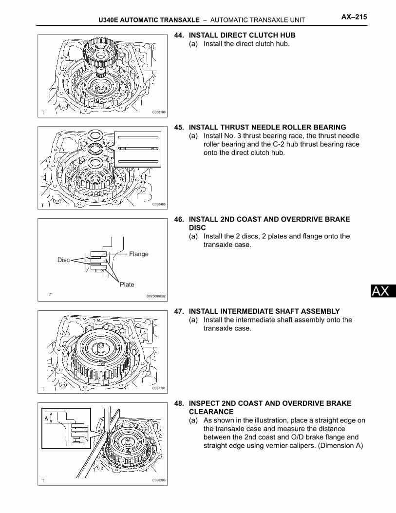
U340E AUTOMATIC TRANSAXLE – AUTOMATIC TRANSAXLE UNIT AX–215
X
A44. INSTALL DIRECT CLUTCH HUB(a) Install the direct clutch hub.
45. INSTALL THRUST NEEDLE ROLLER BEARING(a) Install No. 3 thrust bearing race, the thrust needle
roller bearing and the C-2 hub thrust bearing race onto the direct clutch hub.
46. INSTALL 2ND COAST AND OVERDRIVE BRAKE DISC(a) Install the 2 discs, 2 plates and flange onto the
transaxle case.
47. INSTALL INTERMEDIATE SHAFT ASSEMBLY(a) Install the intermediate shaft assembly onto the
transaxle case.
48. INSPECT 2ND COAST AND OVERDRIVE BRAKE CLEARANCE(a) As shown in the illustration, place a straight edge on
the transaxle case and measure the distance between the 2nd coast and O/D brake flange and straight edge using vernier calipers. (Dimension A)
C068196
C068465
Flange
Plate
Disc
D025099E02
C067781
C068205
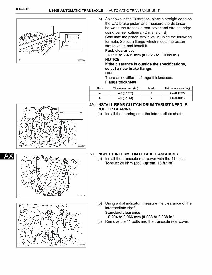
AX–216 U340E AUTOMATIC TRANSAXLE – AUTOMATIC TRANSAXLE UNIT
AX
(b) As shown in the illustration, place a straight edge on the O/D brake piston and measure the distance between the transaxle rear cover and straight edge using vernier calipers. (Dimension B)Calculate the piston stroke value using the following formula. Select a flange which meets the piston stroke value and install it.Pack clearance:
2.091 to 2.491 mm (0.0823 to 0.0981 in.)NOTICE:If the clearance is outside the specifications, select a new brake flange.HINT:There are 4 different flange thicknesses.Flange thickness
49. INSTALL REAR CLUTCH DRUM THRUST NEEDLE ROLLER BEARING(a) Install the bearing onto the intermediate shaft.
50. INSPECT INTERMEDIATE SHAFT ASSEMBLY(a) Install the transaxle rear cover with the 11 bolts.
Torque: 25 N*m (250 kgf*cm, 18 ft.*lbf)
(b) Using a dial indicator, measure the clearance of the intermediate shaft.Standard clearance:
0.204 to 0.966 mm (0.008 to 0.038 in.)(c) Remove the 11 bolts and the transaxle rear cover.
C068206
Mark Thickness mm (in.) Mark Thickness mm (in,)
4 4.0 (0.1575) 6 4.4 (0.1732)
5 4.2 (0.1654) 7 4.6 (0.1811)
C068467
C067778
D025043
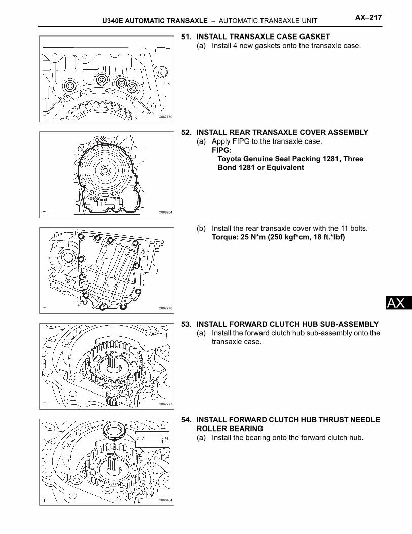
U340E AUTOMATIC TRANSAXLE – AUTOMATIC TRANSAXLE UNIT AX–217
X
A51. INSTALL TRANSAXLE CASE GASKET(a) Install 4 new gaskets onto the transaxle case.
52. INSTALL REAR TRANSAXLE COVER ASSEMBLY(a) Apply FIPG to the transaxle case.
FIPG:Toyota Genuine Seal Packing 1281, Three Bond 1281 or Equivalent
(b) Install the rear transaxle cover with the 11 bolts.Torque: 25 N*m (250 kgf*cm, 18 ft.*lbf)
53. INSTALL FORWARD CLUTCH HUB SUB-ASSEMBLY(a) Install the forward clutch hub sub-assembly onto the
transaxle case.
54. INSTALL FORWARD CLUTCH HUB THRUST NEEDLE ROLLER BEARING(a) Install the bearing onto the forward clutch hub.
C067779
C068204
C067778
C067777
C068464
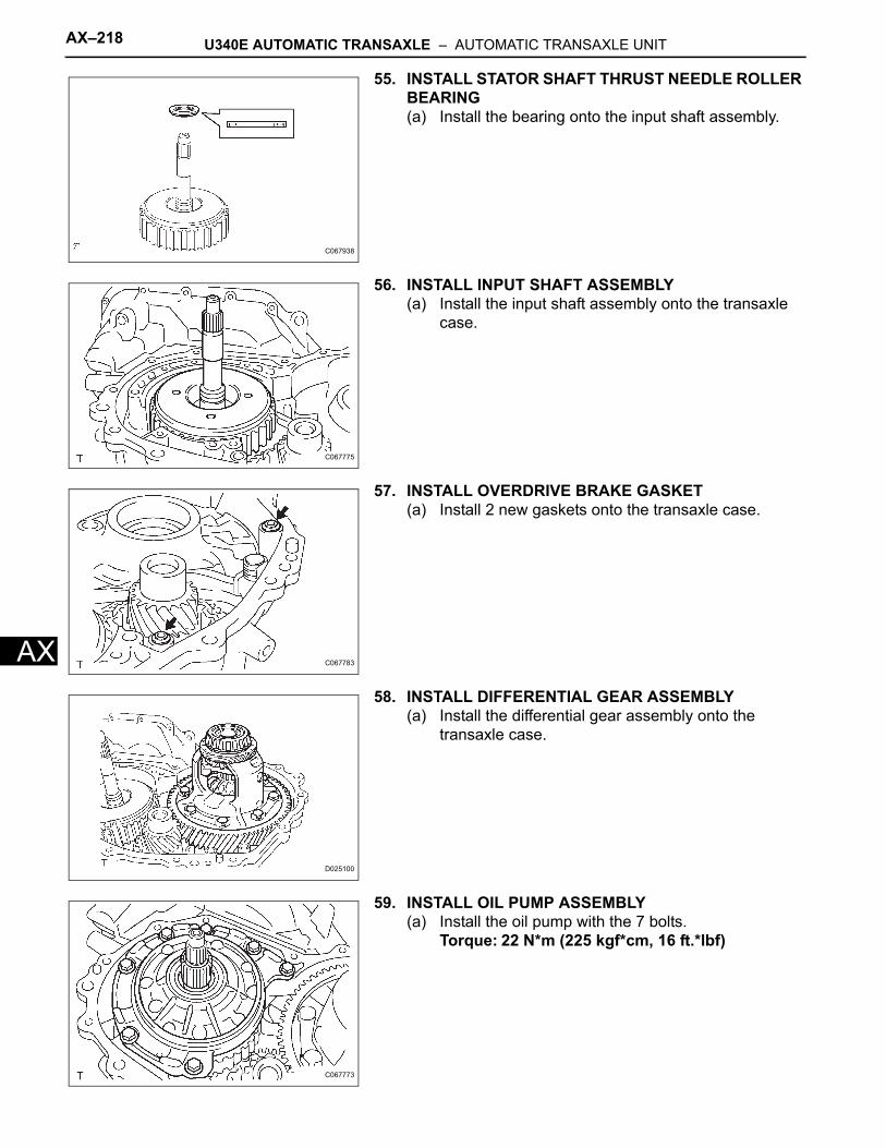
AX–218 U340E AUTOMATIC TRANSAXLE – AUTOMATIC TRANSAXLE UNIT
AX
55. INSTALL STATOR SHAFT THRUST NEEDLE ROLLER BEARING(a) Install the bearing onto the input shaft assembly.
56. INSTALL INPUT SHAFT ASSEMBLY(a) Install the input shaft assembly onto the transaxle
case.
57. INSTALL OVERDRIVE BRAKE GASKET(a) Install 2 new gaskets onto the transaxle case.
58. INSTALL DIFFERENTIAL GEAR ASSEMBLY(a) Install the differential gear assembly onto the
transaxle case.
59. INSTALL OIL PUMP ASSEMBLY(a) Install the oil pump with the 7 bolts.
Torque: 22 N*m (225 kgf*cm, 16 ft.*lbf)
C067938
C067775
C067783
D025100
C067773
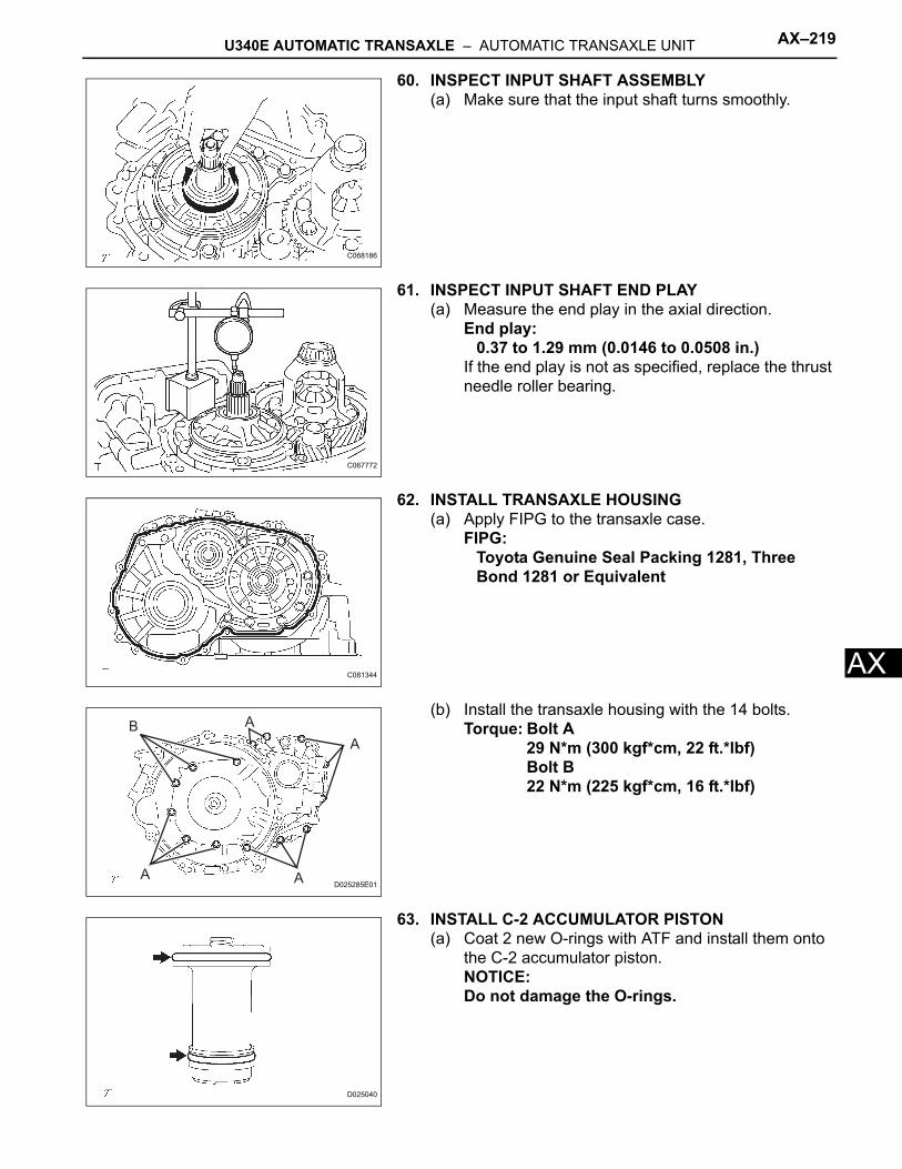
U340E AUTOMATIC TRANSAXLE – AUTOMATIC TRANSAXLE UNIT AX–219
X
A60. INSPECT INPUT SHAFT ASSEMBLY(a) Make sure that the input shaft turns smoothly.
61. INSPECT INPUT SHAFT END PLAY(a) Measure the end play in the axial direction.
End play:0.37 to 1.29 mm (0.0146 to 0.0508 in.)
If the end play is not as specified, replace the thrust needle roller bearing.
62. INSTALL TRANSAXLE HOUSING(a) Apply FIPG to the transaxle case.
FIPG:Toyota Genuine Seal Packing 1281, Three Bond 1281 or Equivalent
(b) Install the transaxle housing with the 14 bolts.Torque: Bolt A
29 N*m (300 kgf*cm, 22 ft.*lbf)Bolt B22 N*m (225 kgf*cm, 16 ft.*lbf)
63. INSTALL C-2 ACCUMULATOR PISTON(a) Coat 2 new O-rings with ATF and install them onto
the C-2 accumulator piston.NOTICE:Do not damage the O-rings.
C068186
C067772
C081344
AB
A
AAD025285E01
D025040
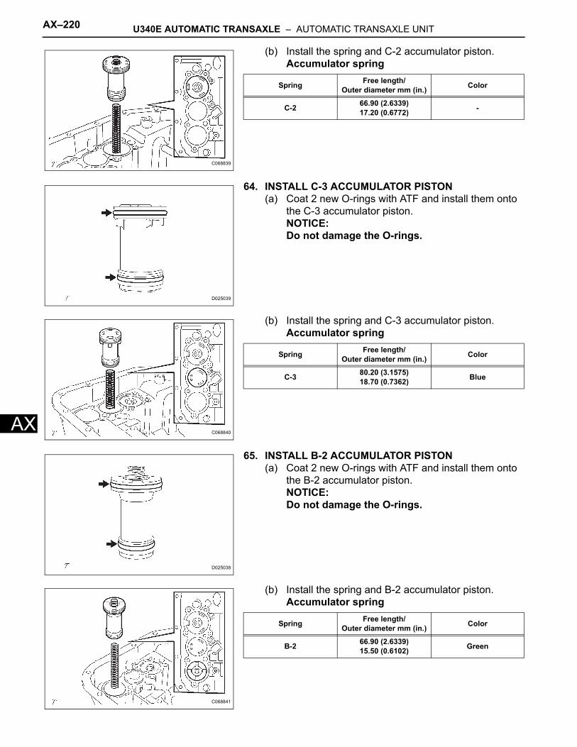
AX–220 U340E AUTOMATIC TRANSAXLE – AUTOMATIC TRANSAXLE UNIT
AX
(b) Install the spring and C-2 accumulator piston.Accumulator spring
64. INSTALL C-3 ACCUMULATOR PISTON(a) Coat 2 new O-rings with ATF and install them onto
the C-3 accumulator piston.NOTICE:Do not damage the O-rings.
(b) Install the spring and C-3 accumulator piston.Accumulator spring
65. INSTALL B-2 ACCUMULATOR PISTON(a) Coat 2 new O-rings with ATF and install them onto
the B-2 accumulator piston.NOTICE:Do not damage the O-rings.
(b) Install the spring and B-2 accumulator piston.Accumulator spring
C068839
Spring Free length/Outer diameter mm (in.) Color
C-2 66.90 (2.6339)17.20 (0.6772) -
D025039
C068840
Spring Free length/Outer diameter mm (in.) Color
C-3 80.20 (3.1575)18.70 (0.7362) Blue
D025038
C068841
Spring Free length/Outer diameter mm (in.) Color
B-2 66.90 (2.6339)15.50 (0.6102) Green
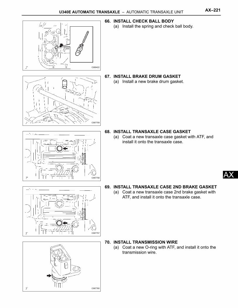
U340E AUTOMATIC TRANSAXLE – AUTOMATIC TRANSAXLE UNIT AX–221
X
A66. INSTALL CHECK BALL BODY(a) Install the spring and check ball body.
67. INSTALL BRAKE DRUM GASKET(a) Install a new brake drum gasket.
68. INSTALL TRANSAXLE CASE GASKET(a) Coat a new transaxle case gasket with ATF, and
install it onto the transaxle case.
69. INSTALL TRANSAXLE CASE 2ND BRAKE GASKET(a) Coat a new transaxle case 2nd brake gasket with
ATF, and install it onto the transaxle case.
70. INSTALL TRANSMISSION WIRE(a) Coat a new O-ring with ATF, and install it onto the
transmission wire.
C069422
C067759
C067758
C067757
C067760
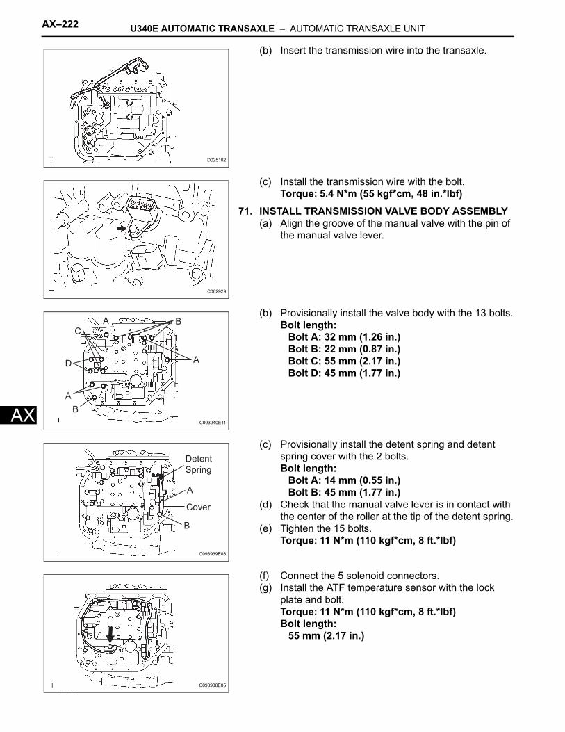
AX–222 U340E AUTOMATIC TRANSAXLE – AUTOMATIC TRANSAXLE UNIT
AX
(b) Insert the transmission wire into the transaxle.
(c) Install the transmission wire with the bolt.Torque: 5.4 N*m (55 kgf*cm, 48 in.*lbf)
71. INSTALL TRANSMISSION VALVE BODY ASSEMBLY(a) Align the groove of the manual valve with the pin of
the manual valve lever.
(b) Provisionally install the valve body with the 13 bolts.Bolt length:
Bolt A: 32 mm (1.26 in.)Bolt B: 22 mm (0.87 in.)Bolt C: 55 mm (2.17 in.)Bolt D: 45 mm (1.77 in.)
(c) Provisionally install the detent spring and detent spring cover with the 2 bolts.Bolt length:
Bolt A: 14 mm (0.55 in.)Bolt B: 45 mm (1.77 in.)
(d) Check that the manual valve lever is in contact with the center of the roller at the tip of the detent spring.
(e) Tighten the 15 bolts.Torque: 11 N*m (110 kgf*cm, 8 ft.*lbf)
(f) Connect the 5 solenoid connectors.(g) Install the ATF temperature sensor with the lock
plate and bolt.Torque: 11 N*m (110 kgf*cm, 8 ft.*lbf)Bolt length:
55 mm (2.17 in.)
D025102
C062929
B
A
D
CA B
A
C093940E11
Detent
Spring
A
Cover
B
C093939E08
C093938E05
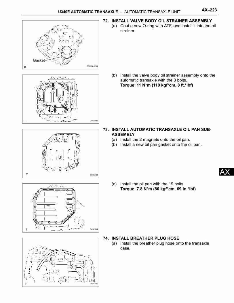
U340E AUTOMATIC TRANSAXLE – AUTOMATIC TRANSAXLE UNIT AX–223
X
A72. INSTALL VALVE BODY OIL STRAINER ASSEMBLY(a) Coat a new O-ring with ATF, and install it into the oil
strainer.
(b) Install the valve body oil strainer assembly onto the automatic transaxle with the 3 bolts.Torque: 11 N*m (110 kgf*cm, 8 ft.*lbf)
73. INSTALL AUTOMATIC TRANSAXLE OIL PAN SUB-ASSEMBLY(a) Install the 2 magnets onto the oil pan.(b) Install a new oil pan gasket onto the oil pan.
(c) Install the oil pan with the 19 bolts.Torque: 7.8 N*m (80 kgf*cm, 69 in.*lbf)
74. INSTALL BREATHER PLUG HOSE(a) Install the breather plug hose onto the transaxle
case.
Gasket
D005904E04
C062685
D025104
C062684
C067752
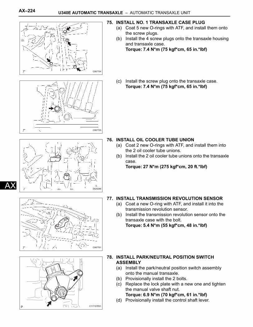
AX–224 U340E AUTOMATIC TRANSAXLE – AUTOMATIC TRANSAXLE UNIT
AX
75. INSTALL NO. 1 TRANSAXLE CASE PLUG(a) Coat 5 new O-rings with ATF, and install them onto
the screw plugs.(b) Install the 4 screw plugs onto the transaxle housing
and transaxle case.Torque: 7.4 N*m (75 kgf*cm, 65 in.*lbf)
(c) Install the screw plug onto the transaxle case.Torque: 7.4 N*m (75 kgf*cm, 65 in.*lbf)
76. INSTALL OIL COOLER TUBE UNION(a) Coat 2 new O-rings with ATF, and install them into
the 2 oil cooler tube unions.(b) Install the 2 oil cooler tube unions onto the transaxle
case.Torque: 27 N*m (275 kgf*cm, 20 ft.*lbf)
77. INSTALL TRANSMISSION REVOLUTION SENSOR(a) Coat a new O-ring with ATF, and install it into the
transmission revolution sensor.(b) Install the transmission revolution sensor onto the
transaxle case with the bolt.Torque: 5.4 N*m (55 kgf*cm, 48 in.*lbf)
78. INSTALL PARK/NEUTRAL POSITION SWITCH ASSEMBLY(a) Install the park/neutral position switch assembly
onto the manual transaxle.(b) Provisionally install the 2 bolts.(c) Replace the lock plate with a new one and tighten
the manual valve shaft nut.Torque: 6.9 N*m (70 kgf*cm, 61 in.*lbf)
(d) Provisionally install the control shaft lever.
C067754
C067755
D025286
C067751
C117107E01
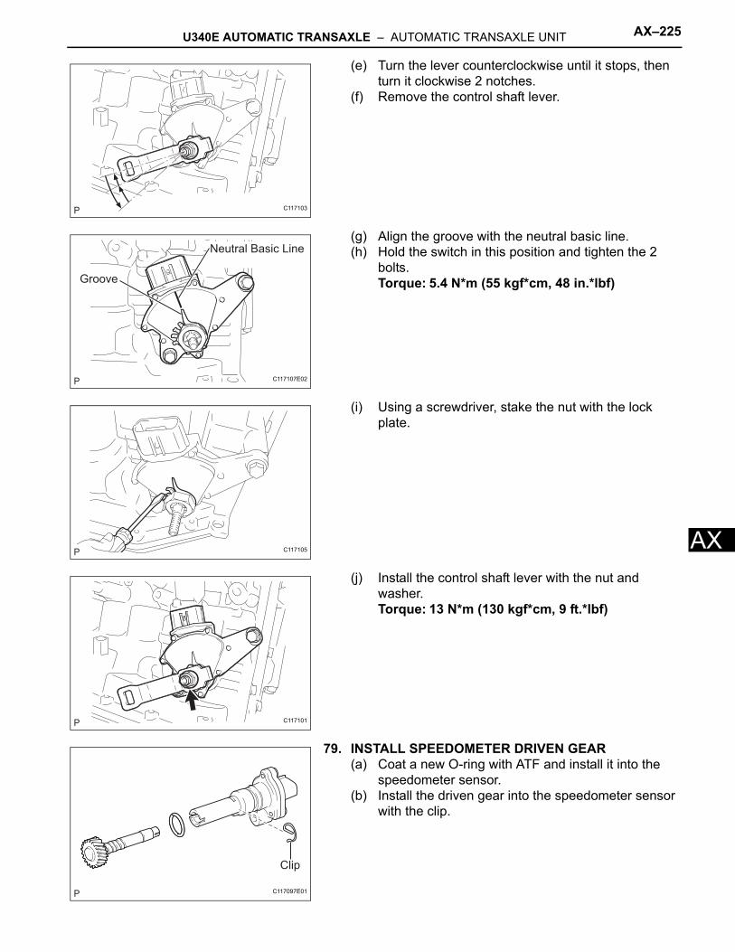
U340E AUTOMATIC TRANSAXLE – AUTOMATIC TRANSAXLE UNIT AX–225
X
A(e) Turn the lever counterclockwise until it stops, then turn it clockwise 2 notches.
(f) Remove the control shaft lever.
(g) Align the groove with the neutral basic line.(h) Hold the switch in this position and tighten the 2
bolts.Torque: 5.4 N*m (55 kgf*cm, 48 in.*lbf)
(i) Using a screwdriver, stake the nut with the lock plate.
(j) Install the control shaft lever with the nut and washer.Torque: 13 N*m (130 kgf*cm, 9 ft.*lbf)
79. INSTALL SPEEDOMETER DRIVEN GEAR(a) Coat a new O-ring with ATF and install it into the
speedometer sensor.(b) Install the driven gear into the speedometer sensor
with the clip.
C117103
Neutral Basic Line
Groove
C117107E02
C117105
C117101
Clip
C117097E01
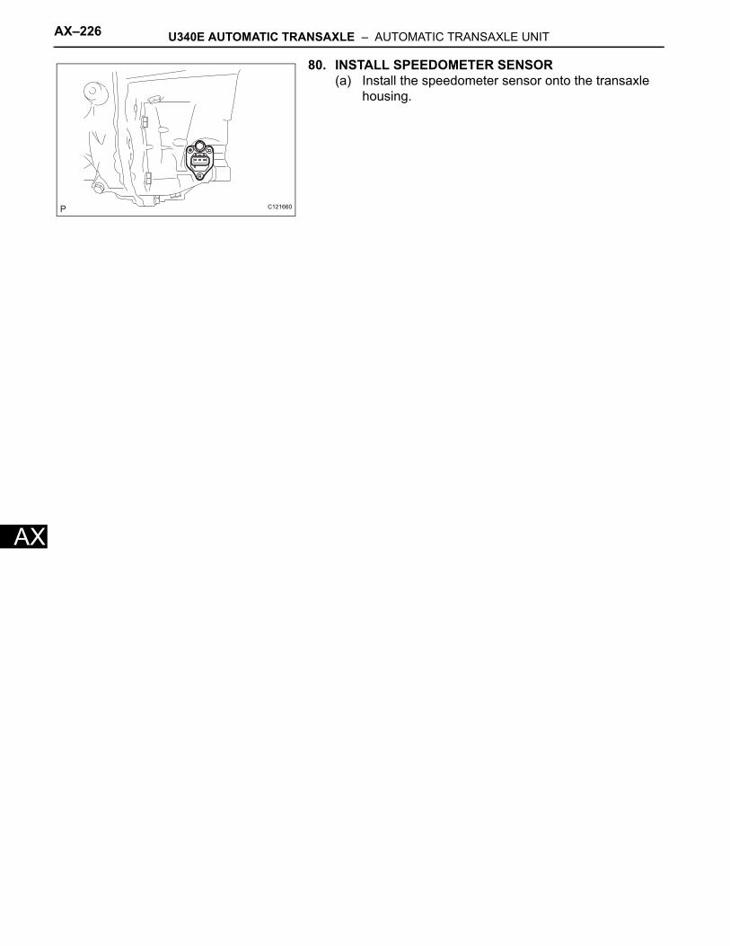
AX–226 U340E AUTOMATIC TRANSAXLE – AUTOMATIC TRANSAXLE UNIT
AX
80. INSTALL SPEEDOMETER SENSOR(a) Install the speedometer sensor onto the transaxle
housing.
C121660
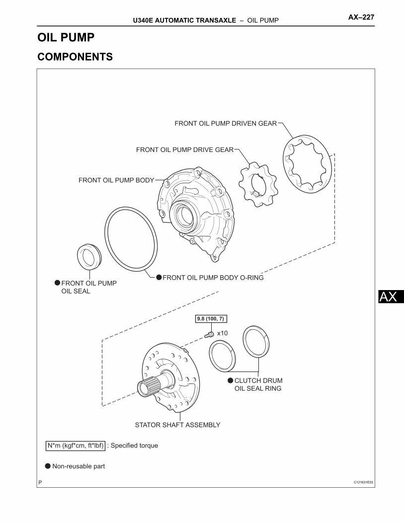
U340E AUTOMATIC TRANSAXLE – OIL PUMP AX–227
X
ATRANSMISSIONU340E AUTOMATIC TRANSAXLEOIL PUMPCOMPONENTS
FRONT OIL PUMP BODY O-RING
FRONT OIL PUMP DRIVE GEAR
FRONT OIL PUMP DRIVEN GEAR
FRONT OIL PUMP
OIL SEAL
STATOR SHAFT ASSEMBLY
FRONT OIL PUMP BODY
x10
9.8 (100, 7)
N*m (kgf*cm, ft*lbf) : Specified torque
Non-reusable part
CLUTCH DRUM
OIL SEAL RING
C121631E03
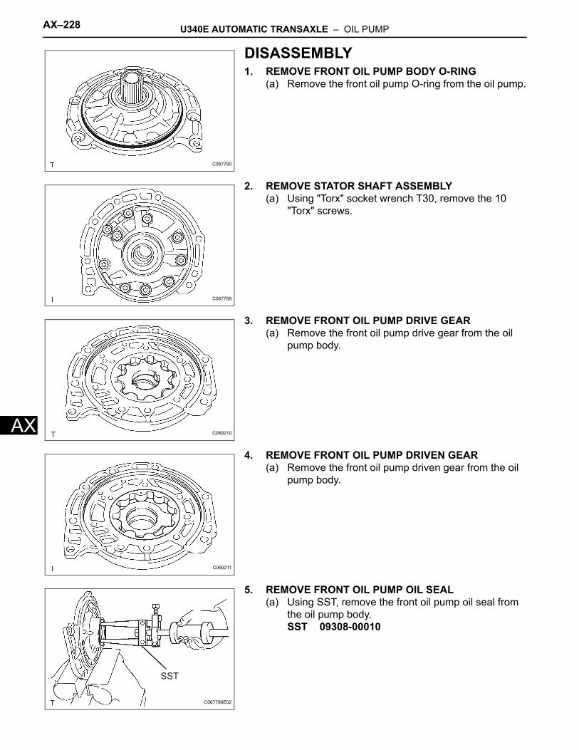
AX–228 U340E AUTOMATIC TRANSAXLE – OIL PUMP
AX
DISASSEMBLY1. REMOVE FRONT OIL PUMP BODY O-RING
(a) Remove the front oil pump O-ring from the oil pump.
2. REMOVE STATOR SHAFT ASSEMBLY(a) Using "Torx" socket wrench T30, remove the 10
"Torx" screws.
3. REMOVE FRONT OIL PUMP DRIVE GEAR(a) Remove the front oil pump drive gear from the oil
pump body.
4. REMOVE FRONT OIL PUMP DRIVEN GEAR(a) Remove the front oil pump driven gear from the oil
pump body.
5. REMOVE FRONT OIL PUMP OIL SEAL(a) Using SST, remove the front oil pump oil seal from
the oil pump body.SST 09308-00010
C067790
C067789
C069210
C069211
SST
C067796E02
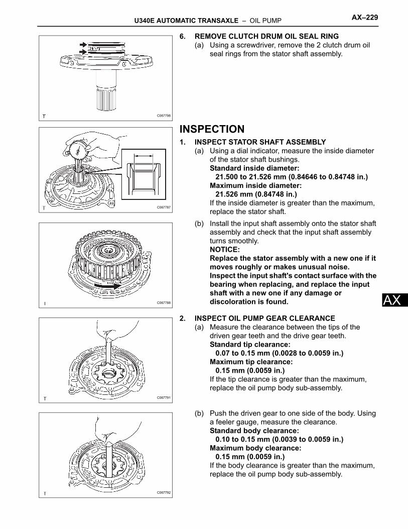
U340E AUTOMATIC TRANSAXLE – OIL PUMP AX–229
X
A6. REMOVE CLUTCH DRUM OIL SEAL RING(a) Using a screwdriver, remove the 2 clutch drum oil
seal rings from the stator shaft assembly.
INSPECTION1. INSPECT STATOR SHAFT ASSEMBLY
(a) Using a dial indicator, measure the inside diameter of the stator shaft bushings.Standard inside diameter:
21.500 to 21.526 mm (0.84646 to 0.84748 in.)Maximum inside diameter:
21.526 mm (0.84748 in.)If the inside diameter is greater than the maximum, replace the stator shaft.
(b) Install the input shaft assembly onto the stator shaft assembly and check that the input shaft assembly turns smoothly.NOTICE:Replace the stator assembly with a new one if it moves roughly or makes unusual noise. Inspect the input shaft's contact surface with the bearing when replacing, and replace the input shaft with a new one if any damage or discoloration is found.
2. INSPECT OIL PUMP GEAR CLEARANCE(a) Measure the clearance between the tips of the
driven gear teeth and the drive gear teeth.Standard tip clearance:
0.07 to 0.15 mm (0.0028 to 0.0059 in.)Maximum tip clearance:
0.15 mm (0.0059 in.)If the tip clearance is greater than the maximum, replace the oil pump body sub-assembly.
(b) Push the driven gear to one side of the body. Using a feeler gauge, measure the clearance.Standard body clearance:
0.10 to 0.15 mm (0.0039 to 0.0059 in.)Maximum body clearance:
0.15 mm (0.0059 in.)If the body clearance is greater than the maximum, replace the oil pump body sub-assembly.
C067798
C067787
C067788
C067791
C067792
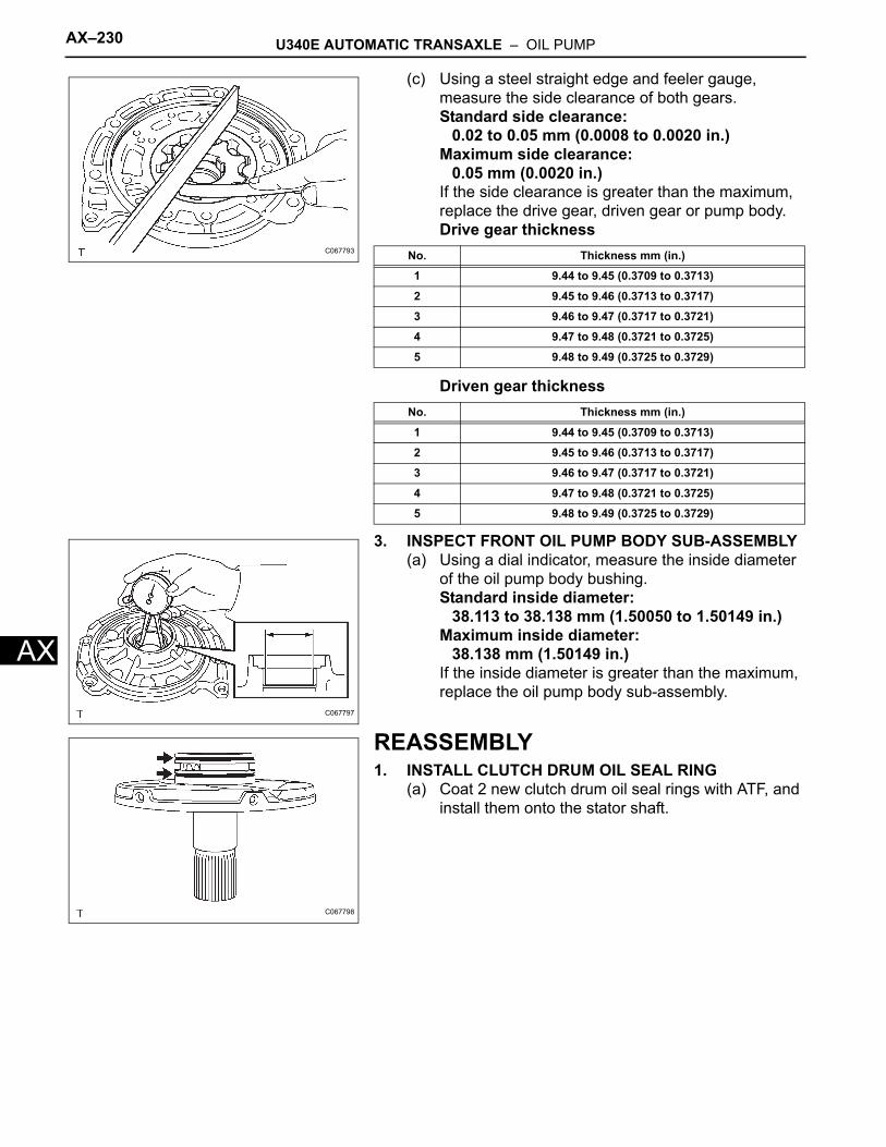
AX–230 U340E AUTOMATIC TRANSAXLE – OIL PUMP
AX
(c) Using a steel straight edge and feeler gauge, measure the side clearance of both gears.Standard side clearance:
0.02 to 0.05 mm (0.0008 to 0.0020 in.)Maximum side clearance:
0.05 mm (0.0020 in.)If the side clearance is greater than the maximum, replace the drive gear, driven gear or pump body.Drive gear thickness
Driven gear thickness
3. INSPECT FRONT OIL PUMP BODY SUB-ASSEMBLY(a) Using a dial indicator, measure the inside diameter
of the oil pump body bushing.Standard inside diameter:
38.113 to 38.138 mm (1.50050 to 1.50149 in.)Maximum inside diameter:
38.138 mm (1.50149 in.)If the inside diameter is greater than the maximum, replace the oil pump body sub-assembly.
REASSEMBLY1. INSTALL CLUTCH DRUM OIL SEAL RING
(a) Coat 2 new clutch drum oil seal rings with ATF, and install them onto the stator shaft.
C067793 No. Thickness mm (in.)
1 9.44 to 9.45 (0.3709 to 0.3713)
2 9.45 to 9.46 (0.3713 to 0.3717)
3 9.46 to 9.47 (0.3717 to 0.3721)
4 9.47 to 9.48 (0.3721 to 0.3725)
5 9.48 to 9.49 (0.3725 to 0.3729)
No. Thickness mm (in.)
1 9.44 to 9.45 (0.3709 to 0.3713)
2 9.45 to 9.46 (0.3713 to 0.3717)
3 9.46 to 9.47 (0.3717 to 0.3721)
4 9.47 to 9.48 (0.3721 to 0.3725)
5 9.48 to 9.49 (0.3725 to 0.3729)
C067797
C067798
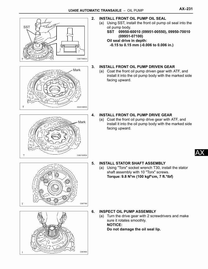
U340E AUTOMATIC TRANSAXLE – OIL PUMP AX–231
X
A2. INSTALL FRONT OIL PUMP OIL SEAL(a) Using SST, install the front oil pump oil seal into the
oil pump body.SST 09950-60010 (09951-00550), 09950-70010
(09951-07100)Oil seal drive in depth:
-0.15 to 0.15 mm (-0.006 to 0.006 in.)
3. INSTALL FRONT OIL PUMP DRIVEN GEAR(a) Coat the front oil pump driven gear with ATF, and
install it into the oil pump body with the marked side facing upward.
4. INSTALL FRONT OIL PUMP DRIVE GEAR(a) Coat the front oil pump drive gear with ATF, and
install it into the oil pump body with the marked side facing upward.
5. INSTALL STATOR SHAFT ASSEMBLY(a) Using "Torx" socket wrench T30, install the stator
shaft assembly with 10 "Torx" screws.Torque: 9.8 N*m (100 kgf*cm, 7 ft.*lbf)
6. INSPECT OIL PUMP ASSEMBLY(a) Turn the drive gear with 2 screwdrivers and make
sure it rotates smoothly.NOTICE:Do not damage the oil seal lip.
SST
C067799E03
Mark
D025108E05
Mark
C082193E04
C067789
C067800
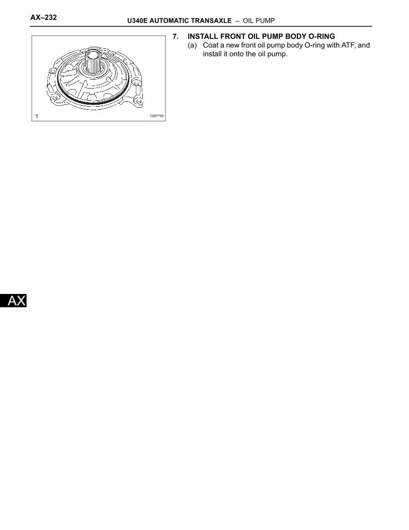
AX–232 U340E AUTOMATIC TRANSAXLE – OIL PUMP
AX
7. INSTALL FRONT OIL PUMP BODY O-RING(a) Coat a new front oil pump body O-ring with ATF, and
install it onto the oil pump.
C067790
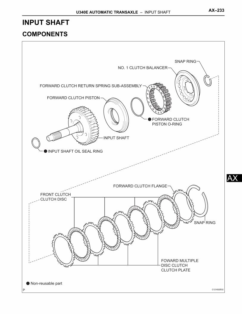
U340E AUTOMATIC TRANSAXLE – INPUT SHAFT AX–233
X
ATRANSMISSIONU340E AUTOMATIC TRANSAXLEINPUT SHAFTCOMPONENTS
FORWARD CLUTCH
PISTON O-RING
FORWARD CLUTCH RETURN SPRING SUB-ASSEMBLY
FRONT CLUTCH
CLUTCH DISC
INPUT SHAFT OIL SEAL RING
FOWARD MULTIPLE
DISC CLUTCH
CLUTCH PLATE
FORWARD CLUTCH FLANGE
SNAP RING
INPUT SHAFT
SNAP RING
Non-reusable part
NO. 1 CLUTCH BALANCER
FORWARD CLUTCH PISTON
C121632E02
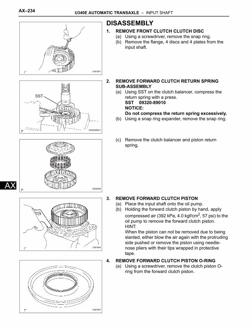
AX–234 U340E AUTOMATIC TRANSAXLE – INPUT SHAFT
AX
DISASSEMBLY1. REMOVE FRONT CLUTCH CLUTCH DISC
(a) Using a screwdriver, remove the snap ring.(b) Remove the flange, 4 discs and 4 plates from the
input shaft.
2. REMOVE FORWARD CLUTCH RETURN SPRING SUB-ASSEMBLY(a) Using SST on the clutch balancer, compress the
return spring with a press.SST 09320-89010NOTICE:Do not compress the return spring excessively.
(b) Using a snap ring expander, remove the snap ring.
(c) Remove the clutch balancer and piston return spring.
3. REMOVE FORWARD CLUTCH PISTON(a) Place the input shaft onto the oil pump.(b) Holding the forward clutch piston by hand, apply
compressed air (392 kPa, 4.0 kgf/cm2, 57 psi) to the oil pump to remove the forward clutch piston.HINT:When the piston can not be removed due to being slanted, either blow the air again with the protruding side pushed or remove the piston using needle-nose pliers with their tips wrapped in protective tape.
4. REMOVE FORWARD CLUTCH PISTON O-RING(a) Using a screwdriver, remove the clutch piston O-
ring from the forward clutch piston.
C067851
SST
D008368E01
D008369
C067856
C067857
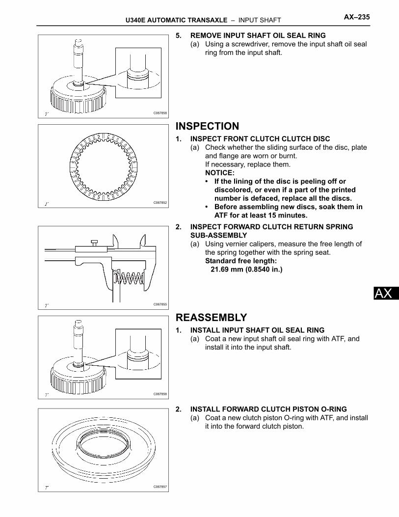
U340E AUTOMATIC TRANSAXLE – INPUT SHAFT AX–235
X
A5. REMOVE INPUT SHAFT OIL SEAL RING(a) Using a screwdriver, remove the input shaft oil seal
ring from the input shaft.
INSPECTION1. INSPECT FRONT CLUTCH CLUTCH DISC
(a) Check whether the sliding surface of the disc, plate and flange are worn or burnt.If necessary, replace them.NOTICE:• If the lining of the disc is peeling off or
discolored, or even if a part of the printed number is defaced, replace all the discs.
• Before assembling new discs, soak them in ATF for at least 15 minutes.
2. INSPECT FORWARD CLUTCH RETURN SPRING SUB-ASSEMBLY(a) Using vernier calipers, measure the free length of
the spring together with the spring seat.Standard free length:
21.69 mm (0.8540 in.)
REASSEMBLY1. INSTALL INPUT SHAFT OIL SEAL RING
(a) Coat a new input shaft oil seal ring with ATF, and install it into the input shaft.
2. INSTALL FORWARD CLUTCH PISTON O-RING(a) Coat a new clutch piston O-ring with ATF, and install
it into the forward clutch piston.
C067858
C067852
C067855
C067858
C067857
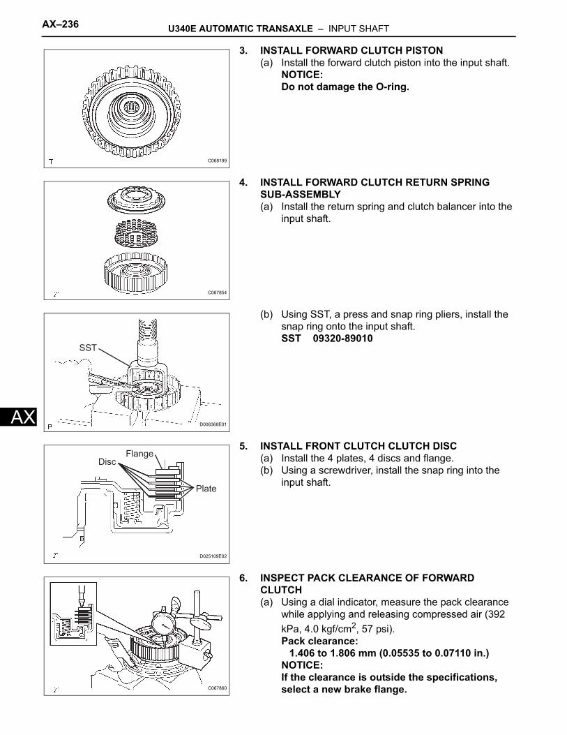
AX–236 U340E AUTOMATIC TRANSAXLE – INPUT SHAFT
AX
3. INSTALL FORWARD CLUTCH PISTON(a) Install the forward clutch piston into the input shaft.
NOTICE:Do not damage the O-ring.
4. INSTALL FORWARD CLUTCH RETURN SPRING SUB-ASSEMBLY(a) Install the return spring and clutch balancer into the
input shaft.
(b) Using SST, a press and snap ring pliers, install the snap ring onto the input shaft.SST 09320-89010
5. INSTALL FRONT CLUTCH CLUTCH DISC(a) Install the 4 plates, 4 discs and flange.(b) Using a screwdriver, install the snap ring into the
input shaft.
6. INSPECT PACK CLEARANCE OF FORWARD CLUTCH(a) Using a dial indicator, measure the pack clearance
while applying and releasing compressed air (392 kPa, 4.0 kgf/cm2, 57 psi).Pack clearance:
1.406 to 1.806 mm (0.05535 to 0.07110 in.)NOTICE:If the clearance is outside the specifications, select a new brake flange.
C068199
C067854
SST
D008368E01
DiscFlange
Plate
D025109E02
C067860
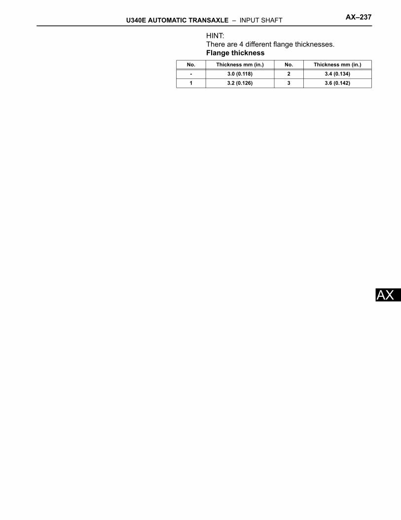
U340E AUTOMATIC TRANSAXLE – INPUT SHAFT AX–237
X
AHINT:There are 4 different flange thicknesses.Flange thickness
No. Thickness mm (in.) No. Thickness mm (in.)
- 3.0 (0.118) 2 3.4 (0.134)
1 3.2 (0.126) 3 3.6 (0.142)
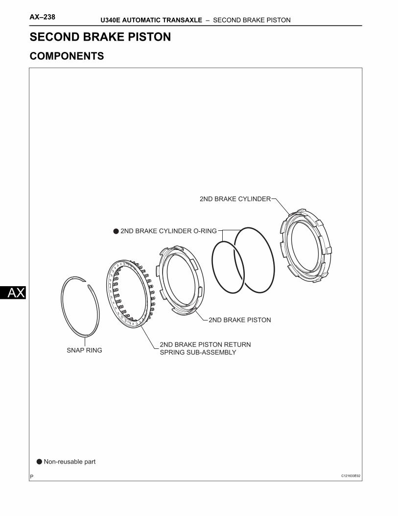
AX–238 U340E AUTOMATIC TRANSAXLE – SECOND BRAKE PISTON
AX
TRANSMISSIONU340E AUTOMATIC TRANSAXLESECOND BRAKE PISTONCOMPONENTS
Non-reusable part
2ND BRAKE CYLINDER O-RING
2ND BRAKE PISTON
SNAP RING
2ND BRAKE CYLINDER
2ND BRAKE PISTON RETURN
SPRING SUB-ASSEMBLY
C121633E02
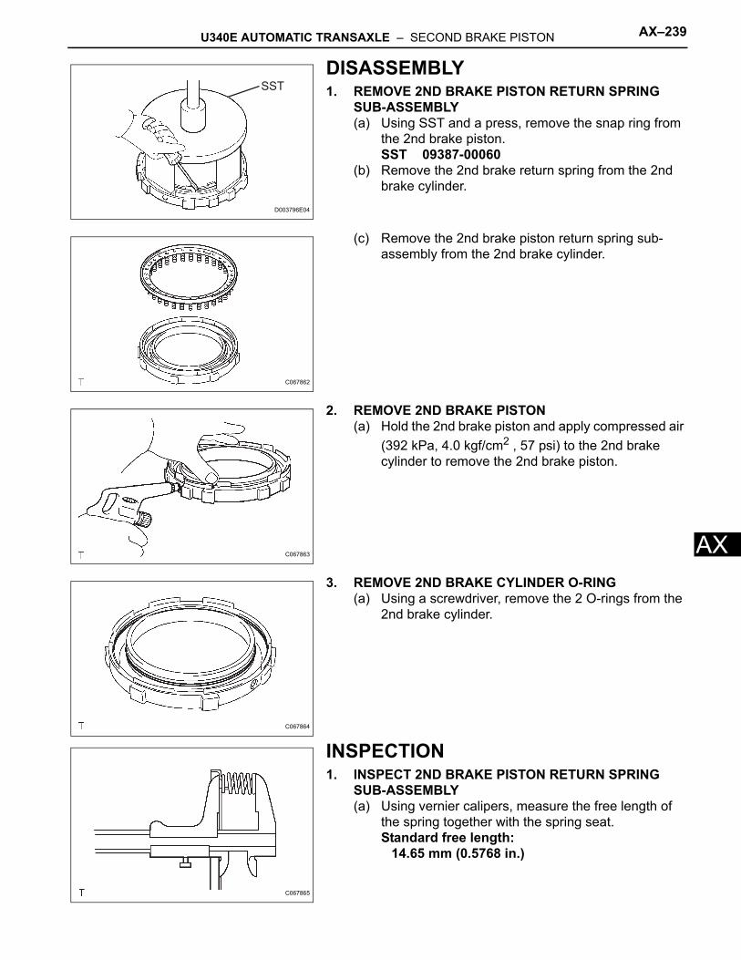
U340E AUTOMATIC TRANSAXLE – SECOND BRAKE PISTON AX–239
X
ADISASSEMBLY1. REMOVE 2ND BRAKE PISTON RETURN SPRING
SUB-ASSEMBLY(a) Using SST and a press, remove the snap ring from
the 2nd brake piston.SST 09387-00060
(b) Remove the 2nd brake return spring from the 2nd brake cylinder.
(c) Remove the 2nd brake piston return spring sub-assembly from the 2nd brake cylinder.
2. REMOVE 2ND BRAKE PISTON(a) Hold the 2nd brake piston and apply compressed air
(392 kPa, 4.0 kgf/cm2 , 57 psi) to the 2nd brake cylinder to remove the 2nd brake piston.
3. REMOVE 2ND BRAKE CYLINDER O-RING(a) Using a screwdriver, remove the 2 O-rings from the
2nd brake cylinder.
INSPECTION1. INSPECT 2ND BRAKE PISTON RETURN SPRING
SUB-ASSEMBLY(a) Using vernier calipers, measure the free length of
the spring together with the spring seat.Standard free length:
14.65 mm (0.5768 in.)
SST
D003796E04
C067862
C067863
C067864
C067865
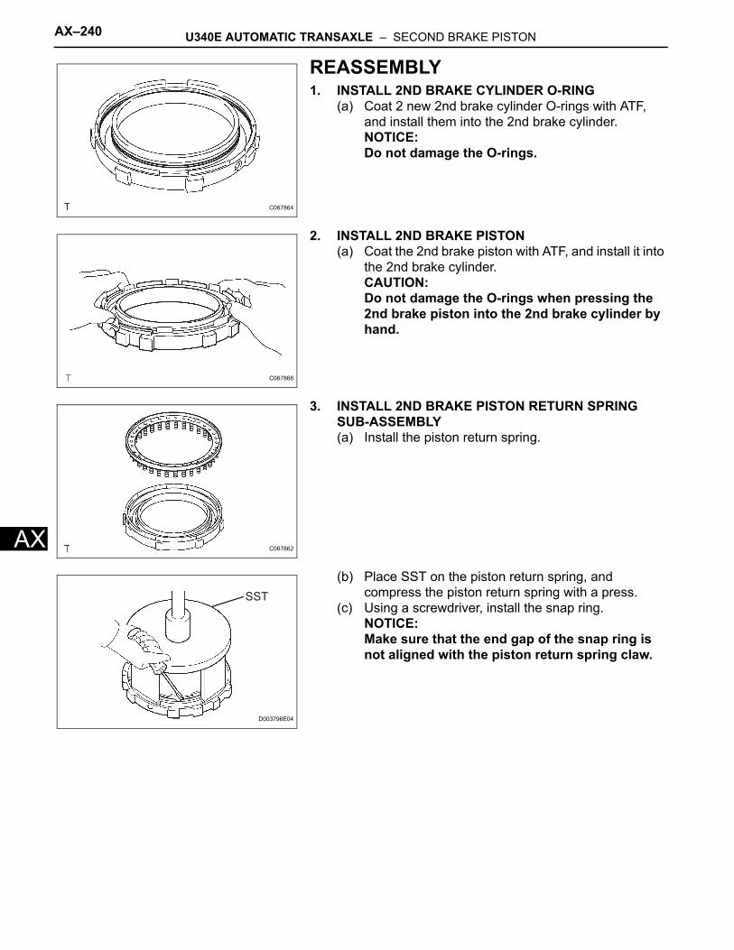
AX–240 U340E AUTOMATIC TRANSAXLE – SECOND BRAKE PISTON
AX
REASSEMBLY1. INSTALL 2ND BRAKE CYLINDER O-RING
(a) Coat 2 new 2nd brake cylinder O-rings with ATF, and install them into the 2nd brake cylinder.NOTICE:Do not damage the O-rings.
2. INSTALL 2ND BRAKE PISTON(a) Coat the 2nd brake piston with ATF, and install it into
the 2nd brake cylinder.CAUTION:Do not damage the O-rings when pressing the 2nd brake piston into the 2nd brake cylinder by hand.
3. INSTALL 2ND BRAKE PISTON RETURN SPRING SUB-ASSEMBLY(a) Install the piston return spring.
(b) Place SST on the piston return spring, and compress the piston return spring with a press.
(c) Using a screwdriver, install the snap ring.NOTICE:Make sure that the end gap of the snap ring is not aligned with the piston return spring claw.
C067864
C067866
C067862
SST
D003796E04
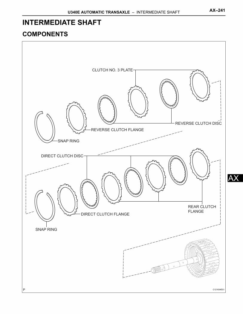
U340E AUTOMATIC TRANSAXLE – INTERMEDIATE SHAFT AX–241
X
ATRANSMISSIONU340E AUTOMATIC TRANSAXLEINTERMEDIATE SHAFTCOMPONENTS
REVERSE CLUTCH DISC
REVERSE CLUTCH FLANGE
CLUTCH NO. 3 PLATE
SNAP RING
DIRECT CLUTCH DISC
DIRECT CLUTCH FLANGE
REAR CLUTCH
FLANGE
SNAP RING
C121634E01
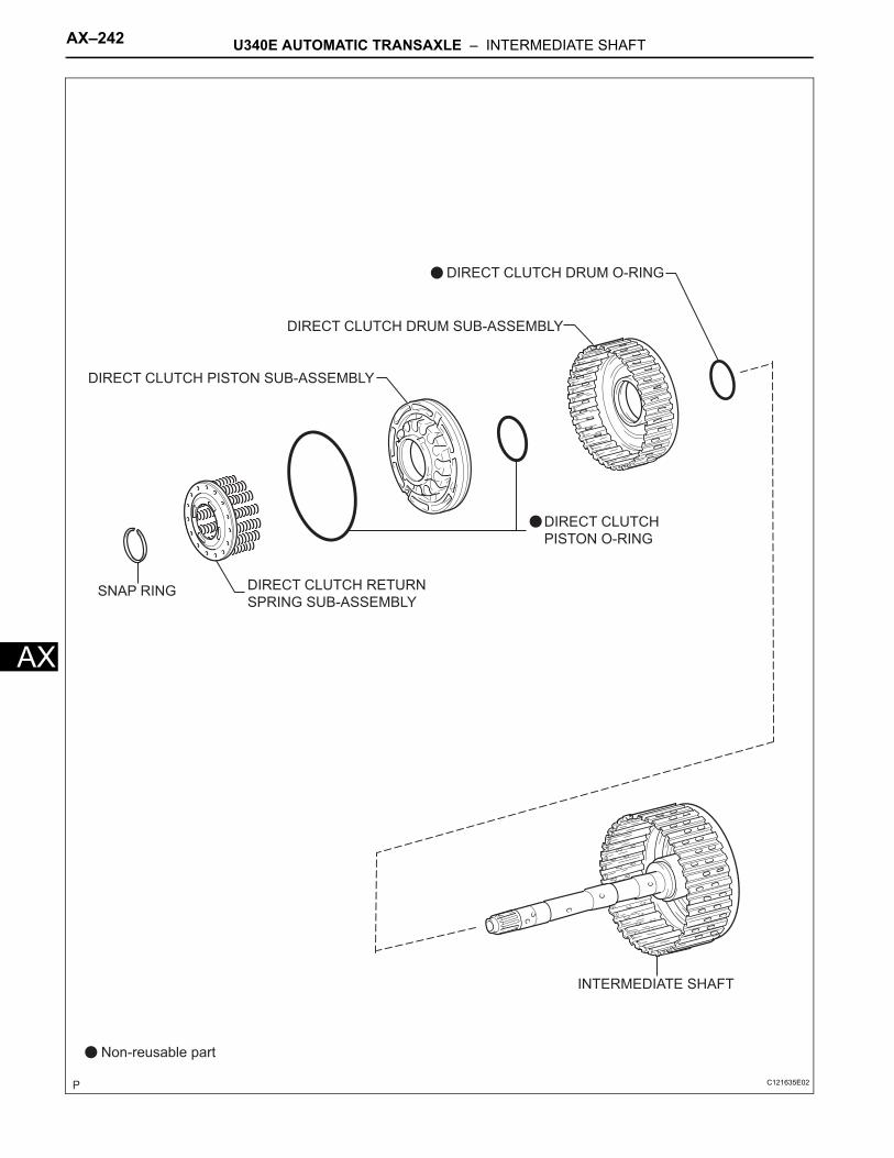
AX–242 U340E AUTOMATIC TRANSAXLE – INTERMEDIATE SHAFT
AX
DIRECT CLUTCH
PISTON O-RING
DIRECT CLUTCH PISTON SUB-ASSEMBLY
DIRECT CLUTCH RETURN
SPRING SUB-ASSEMBLYSNAP RING
INTERMEDIATE SHAFT
Non-reusable part
DIRECT CLUTCH DRUM O-RING
DIRECT CLUTCH DRUM SUB-ASSEMBLY
C121635E02
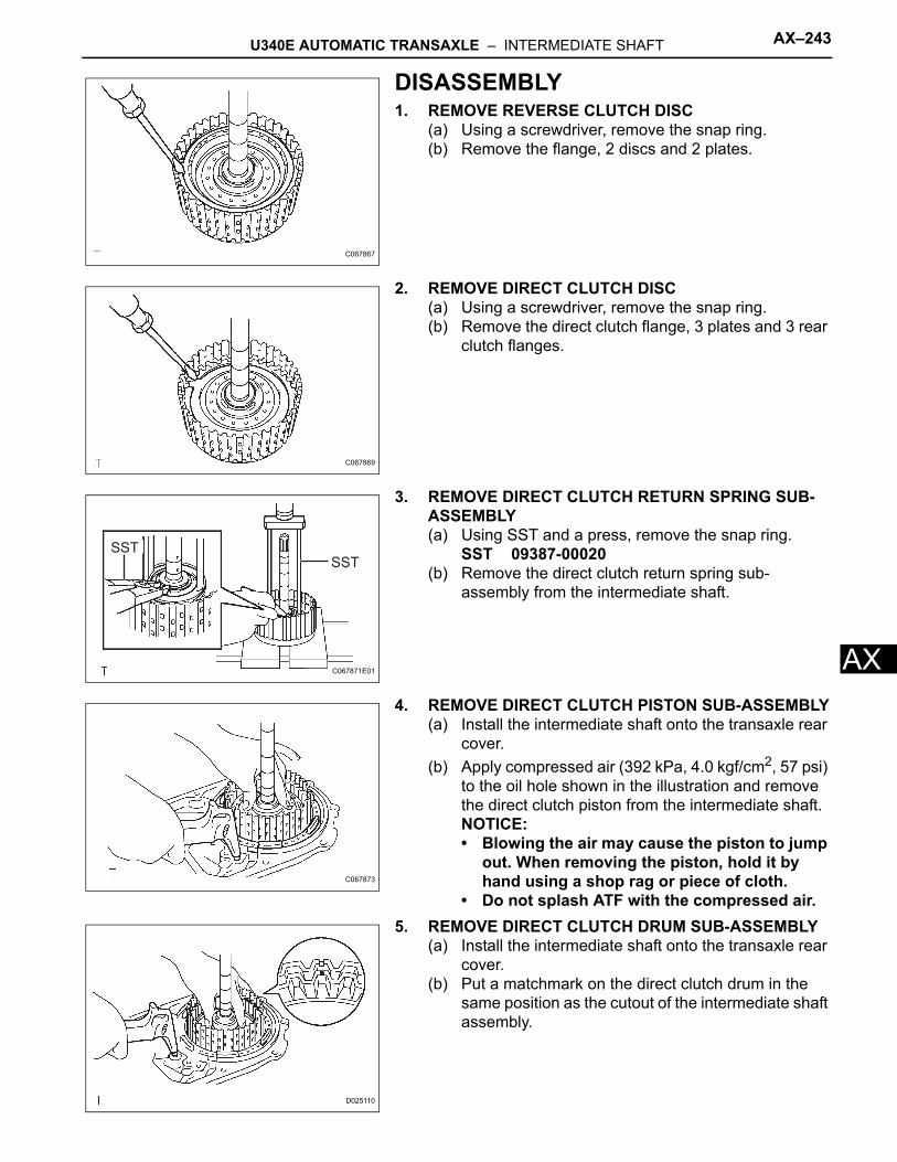
U340E AUTOMATIC TRANSAXLE – INTERMEDIATE SHAFT AX–243
X
ADISASSEMBLY1. REMOVE REVERSE CLUTCH DISC
(a) Using a screwdriver, remove the snap ring.(b) Remove the flange, 2 discs and 2 plates.
2. REMOVE DIRECT CLUTCH DISC(a) Using a screwdriver, remove the snap ring.(b) Remove the direct clutch flange, 3 plates and 3 rear
clutch flanges.
3. REMOVE DIRECT CLUTCH RETURN SPRING SUB-ASSEMBLY(a) Using SST and a press, remove the snap ring.
SST 09387-00020(b) Remove the direct clutch return spring sub-
assembly from the intermediate shaft.
4. REMOVE DIRECT CLUTCH PISTON SUB-ASSEMBLY(a) Install the intermediate shaft onto the transaxle rear
cover.(b) Apply compressed air (392 kPa, 4.0 kgf/cm2, 57 psi)
to the oil hole shown in the illustration and remove the direct clutch piston from the intermediate shaft.NOTICE:• Blowing the air may cause the piston to jump
out. When removing the piston, hold it by hand using a shop rag or piece of cloth.
• Do not splash ATF with the compressed air.5. REMOVE DIRECT CLUTCH DRUM SUB-ASSEMBLY
(a) Install the intermediate shaft onto the transaxle rear cover.
(b) Put a matchmark on the direct clutch drum in the same position as the cutout of the intermediate shaft assembly.
C067867
C067869
SSTSST
C067871E01
C067873
D025110
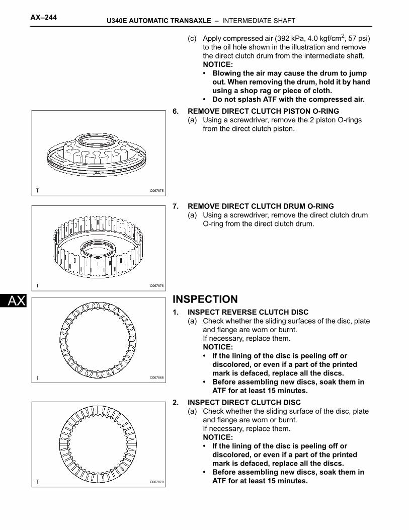
AX–244 U340E AUTOMATIC TRANSAXLE – INTERMEDIATE SHAFT
AX
(c) Apply compressed air (392 kPa, 4.0 kgf/cm2, 57 psi) to the oil hole shown in the illustration and remove the direct clutch drum from the intermediate shaft.NOTICE:• Blowing the air may cause the drum to jump
out. When removing the drum, hold it by hand using a shop rag or piece of cloth.
• Do not splash ATF with the compressed air.6. REMOVE DIRECT CLUTCH PISTON O-RING
(a) Using a screwdriver, remove the 2 piston O-rings from the direct clutch piston.
7. REMOVE DIRECT CLUTCH DRUM O-RING(a) Using a screwdriver, remove the direct clutch drum
O-ring from the direct clutch drum.
INSPECTION1. INSPECT REVERSE CLUTCH DISC
(a) Check whether the sliding surfaces of the disc, plate and flange are worn or burnt.If necessary, replace them.NOTICE:• If the lining of the disc is peeling off or
discolored, or even if a part of the printed mark is defaced, replace all the discs.
• Before assembling new discs, soak them in ATF for at least 15 minutes.
2. INSPECT DIRECT CLUTCH DISC(a) Check whether the sliding surface of the disc, plate
and flange are worn or burnt.If necessary, replace them.NOTICE:• If the lining of the disc is peeling off or
discolored, or even if a part of the printed mark is defaced, replace all the discs.
• Before assembling new discs, soak them in ATF for at least 15 minutes.
C067875
C067876
C067868
C067870
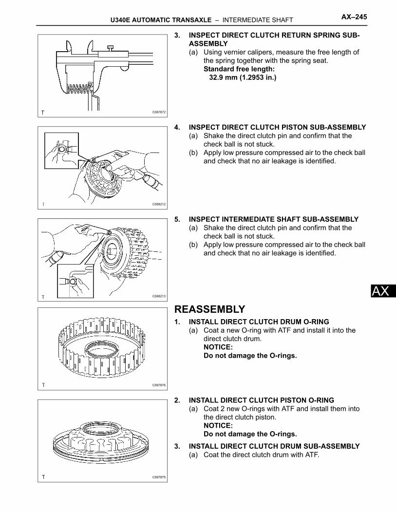
U340E AUTOMATIC TRANSAXLE – INTERMEDIATE SHAFT AX–245
X
A3. INSPECT DIRECT CLUTCH RETURN SPRING SUB-ASSEMBLY(a) Using vernier calipers, measure the free length of
the spring together with the spring seat.Standard free length:
32.9 mm (1.2953 in.)
4. INSPECT DIRECT CLUTCH PISTON SUB-ASSEMBLY(a) Shake the direct clutch pin and confirm that the
check ball is not stuck.(b) Apply low pressure compressed air to the check ball
and check that no air leakage is identified.
5. INSPECT INTERMEDIATE SHAFT SUB-ASSEMBLY(a) Shake the direct clutch pin and confirm that the
check ball is not stuck.(b) Apply low pressure compressed air to the check ball
and check that no air leakage is identified.
REASSEMBLY1. INSTALL DIRECT CLUTCH DRUM O-RING
(a) Coat a new O-ring with ATF and install it into the direct clutch drum.NOTICE:Do not damage the O-rings.
2. INSTALL DIRECT CLUTCH PISTON O-RING(a) Coat 2 new O-rings with ATF and install them into
the direct clutch piston.NOTICE:Do not damage the O-rings.
3. INSTALL DIRECT CLUTCH DRUM SUB-ASSEMBLY(a) Coat the direct clutch drum with ATF.
C067872
C068212
C068213
C067876
C067875
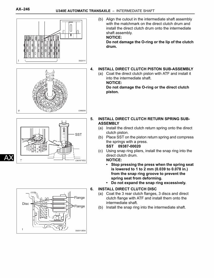
AX–246 U340E AUTOMATIC TRANSAXLE – INTERMEDIATE SHAFT
AX
(b) Align the cutout in the intermediate shaft assembly with the matchmark on the direct clutch drum and install the direct clutch drum onto the intermediate shaft assembly.NOTICE:Do not damage the O-ring or the lip of the clutch drum.
4. INSTALL DIRECT CLUTCH PISTON SUB-ASSEMBLY(a) Coat the direct clutch piston with ATF and install it
into the intermediate shaft.NOTICE:Do not damage the O-ring or the direct clutch piston.
5. INSTALL DIRECT CLUTCH RETURN SPRING SUB-ASSEMBLY(a) Install the direct clutch return spring onto the direct
clutch piston.(b) Place SST on the piston return spring and compress
the springs with a press.SST 09387-00020
(c) Using snap ring pliers, install the snap ring into the direct clutch drum.NOTICE:• Stop pressing the press when the spring seat
is lowered to 1 to 2 mm (0.039 to 0.078 in.) from the snap ring groove to prevent the spring seat from deforming.
• Do not expand the snap ring excessively.6. INSTALL DIRECT CLUTCH DISC
(a) Coat the 3 rear clutch flanges, 3 discs and direct clutch flange with ATF and install them onto the intermediate shaft.
(b) Install the snap ring into the intermediate shaft.
D025111
C068200
SST
C067871E03
Disc
Flange
Flange
D025112E04
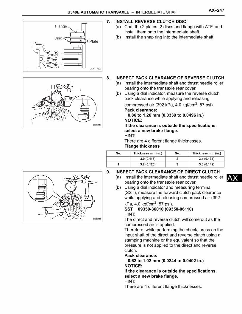
U340E AUTOMATIC TRANSAXLE – INTERMEDIATE SHAFT AX–247
X
A7. INSTALL REVERSE CLUTCH DISC(a) Coat the 2 plates, 2 discs and flange with ATF, and
install them onto the intermediate shaft.(b) Install the snap ring into the intermediate shaft.
8. INSPECT PACK CLEARANCE OF REVERSE CLUTCH(a) Install the intermediate shaft and thrust needle roller
bearing onto the transaxle rear cover.(b) Using a dial indicator, measure the reverse clutch
pack clearance while applying and releasing compressed air (392 kPa, 4.0 kgf/cm2, 57 psi).Pack clearance:
0.86 to 1.26 mm (0.0339 to 0.0496 in.)NOTICE:If the clearance is outside the specifications, select a new brake flange.HINT:There are 4 different flange thicknesses.Flange thickness
9. INSPECT PACK CLEARANCE OF DIRECT CLUTCH(a) Install the intermediate shaft and thrust needle roller
bearing onto the transaxle rear cover.(b) Using a dial indicator and measuring terminal
(SST), measure the forward clutch pack clearance while applying and releasing compressed air (392 kPa, 4.0 kgf/cm2, 57 psi).SST 09350-36010 (09350-06110)HINT:The direct and reverse clutch will come out as the compressed air is applied. Therefore, while performing the check, press on the input shaft of the direct and reverse clutch using a stamping machine or the equivalent so that the pressure is not applied to the direct and reverse clutch.Pack clearance:
0.62 to 1.02 mm (0.0244 to 0.0402 in.)NOTICE:If the clearance is outside the specifications, select a new brake flange.HINT:There are 4 different flange thicknesses.
Flange
DiscPlate
D025113E02
D025114
No. Thickness mm (in.) No. Thickness mm (in.)
- 3.0 (0.118) 2 3.4 (0.134)
1 3.2 (0.126) 3 3.6 (0.142)
D025115
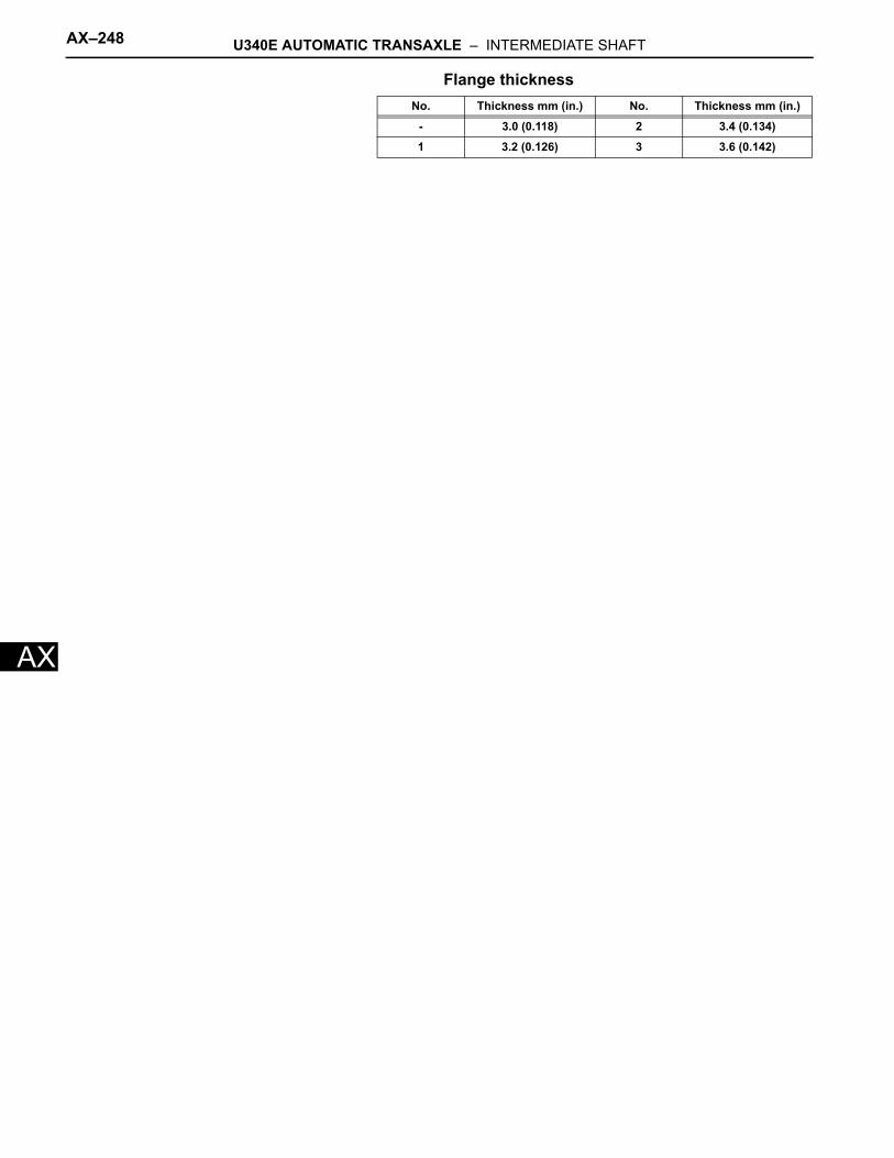
AX–248 U340E AUTOMATIC TRANSAXLE – INTERMEDIATE SHAFT
AX
Flange thicknessNo. Thickness mm (in.) No. Thickness mm (in.)
- 3.0 (0.118) 2 3.4 (0.134)
1 3.2 (0.126) 3 3.6 (0.142)
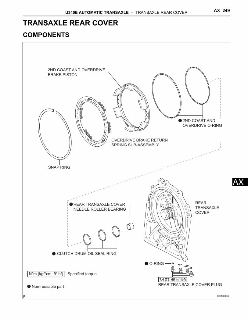
U340E AUTOMATIC TRANSAXLE – TRANSAXLE REAR COVER AX–249
X
ATRANSMISSIONU340E AUTOMATIC TRANSAXLETRANSAXLE REAR COVERCOMPONENTS
2ND COAST AND OVERDRIVE
BRAKE PISTON
2ND COAST AND
OVERDRIVE O-RING
CLUTCH DRUM OIL SEAL RING
OVERDRIVE BRAKE RETURN
SPRING SUB-ASSEMBLY
REAR TRANSAXLE COVER PLUG
7.4 (75, 65 in.*lbf)
O-RING
REAR
TRANSAXLE
COVER
SNAP RING
N*m (kgf*cm, ft*lbf) : Specified torque
Non-reusable part
REAR TRANSAXLE COVER
NEEDLE ROLLER BEARING
C121636E02
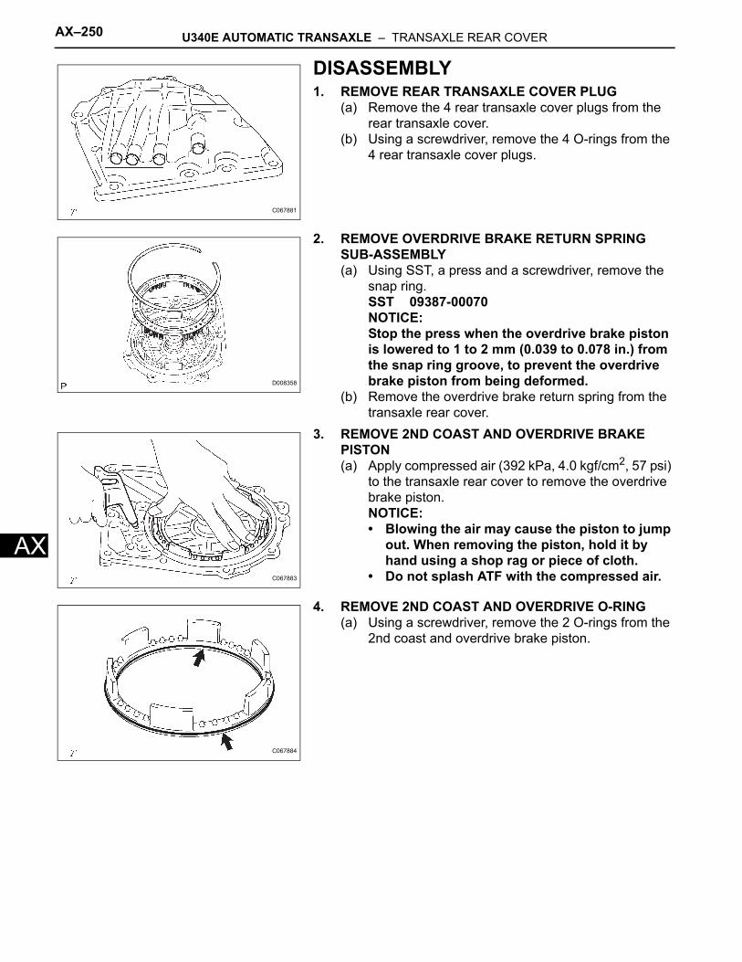
AX–250 U340E AUTOMATIC TRANSAXLE – TRANSAXLE REAR COVER
AX
DISASSEMBLY1. REMOVE REAR TRANSAXLE COVER PLUG
(a) Remove the 4 rear transaxle cover plugs from the rear transaxle cover.
(b) Using a screwdriver, remove the 4 O-rings from the 4 rear transaxle cover plugs.
2. REMOVE OVERDRIVE BRAKE RETURN SPRING SUB-ASSEMBLY(a) Using SST, a press and a screwdriver, remove the
snap ring.SST 09387-00070NOTICE:Stop the press when the overdrive brake piston is lowered to 1 to 2 mm (0.039 to 0.078 in.) from the snap ring groove, to prevent the overdrive brake piston from being deformed.
(b) Remove the overdrive brake return spring from the transaxle rear cover.
3. REMOVE 2ND COAST AND OVERDRIVE BRAKE PISTON(a) Apply compressed air (392 kPa, 4.0 kgf/cm2, 57 psi)
to the transaxle rear cover to remove the overdrive brake piston.NOTICE:• Blowing the air may cause the piston to jump
out. When removing the piston, hold it by hand using a shop rag or piece of cloth.
• Do not splash ATF with the compressed air.
4. REMOVE 2ND COAST AND OVERDRIVE O-RING(a) Using a screwdriver, remove the 2 O-rings from the
2nd coast and overdrive brake piston.
C067881
D008358
C067883
C067884
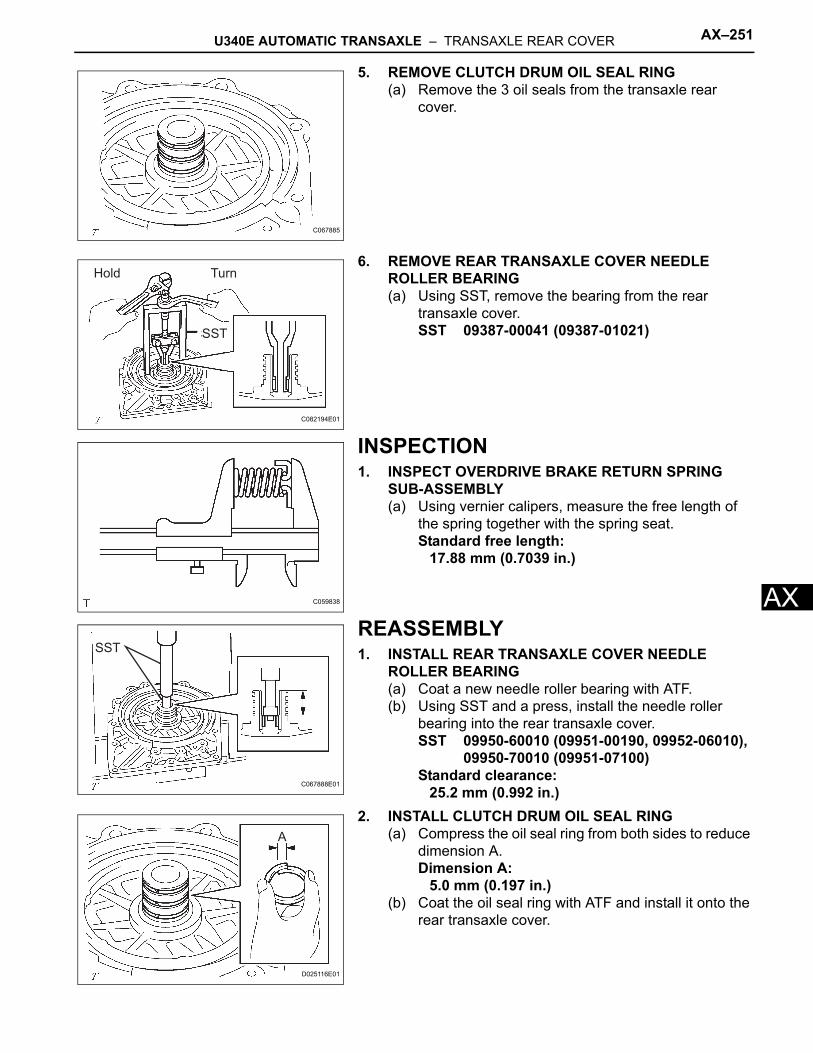
U340E AUTOMATIC TRANSAXLE – TRANSAXLE REAR COVER AX–251
X
A5. REMOVE CLUTCH DRUM OIL SEAL RING(a) Remove the 3 oil seals from the transaxle rear
cover.
6. REMOVE REAR TRANSAXLE COVER NEEDLE ROLLER BEARING(a) Using SST, remove the bearing from the rear
transaxle cover.SST 09387-00041 (09387-01021)
INSPECTION1. INSPECT OVERDRIVE BRAKE RETURN SPRING
SUB-ASSEMBLY(a) Using vernier calipers, measure the free length of
the spring together with the spring seat.Standard free length:
17.88 mm (0.7039 in.)
REASSEMBLY1. INSTALL REAR TRANSAXLE COVER NEEDLE
ROLLER BEARING(a) Coat a new needle roller bearing with ATF.(b) Using SST and a press, install the needle roller
bearing into the rear transaxle cover.SST 09950-60010 (09951-00190, 09952-06010),
09950-70010 (09951-07100)Standard clearance:
25.2 mm (0.992 in.)2. INSTALL CLUTCH DRUM OIL SEAL RING
(a) Compress the oil seal ring from both sides to reduce dimension A.Dimension A:
5.0 mm (0.197 in.)(b) Coat the oil seal ring with ATF and install it onto the
rear transaxle cover.
C067885
Hold Turn
SST
C082194E01
C059838
SST
C067888E01
A
D025116E01
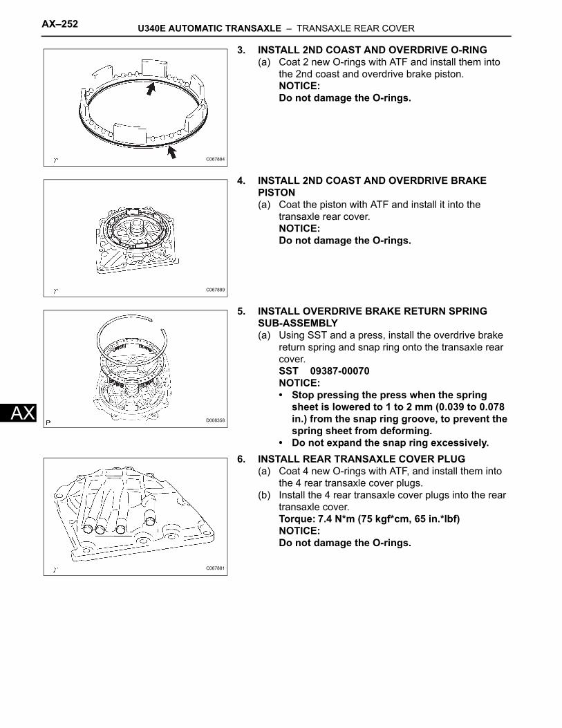
AX–252 U340E AUTOMATIC TRANSAXLE – TRANSAXLE REAR COVER
AX
3. INSTALL 2ND COAST AND OVERDRIVE O-RING(a) Coat 2 new O-rings with ATF and install them into
the 2nd coast and overdrive brake piston.NOTICE:Do not damage the O-rings.
4. INSTALL 2ND COAST AND OVERDRIVE BRAKE PISTON(a) Coat the piston with ATF and install it into the
transaxle rear cover.NOTICE:Do not damage the O-rings.
5. INSTALL OVERDRIVE BRAKE RETURN SPRING SUB-ASSEMBLY(a) Using SST and a press, install the overdrive brake
return spring and snap ring onto the transaxle rear cover.SST 09387-00070NOTICE:• Stop pressing the press when the spring
sheet is lowered to 1 to 2 mm (0.039 to 0.078 in.) from the snap ring groove, to prevent the spring sheet from deforming.
• Do not expand the snap ring excessively.6. INSTALL REAR TRANSAXLE COVER PLUG
(a) Coat 4 new O-rings with ATF, and install them into the 4 rear transaxle cover plugs.
(b) Install the 4 rear transaxle cover plugs into the rear transaxle cover.Torque: 7.4 N*m (75 kgf*cm, 65 in.*lbf)NOTICE:Do not damage the O-rings.
C067884
C067889
D008358
C067881
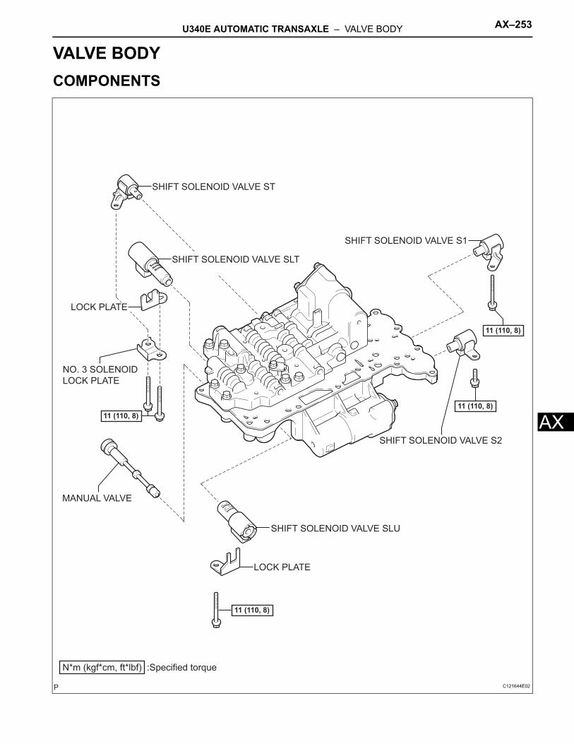
U340E AUTOMATIC TRANSAXLE – VALVE BODY AX–253
X
ATRANSMISSIONU340E AUTOMATIC TRANSAXLEVALVE BODYCOMPONENTS
MANUAL VALVE
SHIFT SOLENOID VALVE S1
SHIFT SOLENOID VALVE S2
SHIFT SOLENOID VALVE SLU
LOCK PLATE
N*m (kgf*cm, ft*lbf) :Specified torque
11 (110, 8)
11 (110, 8)11 (110, 8)
11 (110, 8)
LOCK PLATE
NO. 3 SOLENOID
LOCK PLATE
SHIFT SOLENOID VALVE ST
SHIFT SOLENOID VALVE SLT
C121644E02
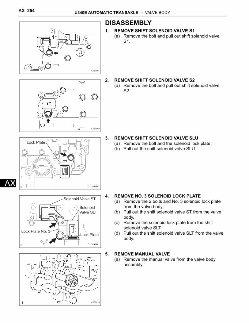
AX–254 U340E AUTOMATIC TRANSAXLE – VALVE BODY
AX
DISASSEMBLY1. REMOVE SHIFT SOLENOID VALVE S1
(a) Remove the bolt and pull out shift solenoid valve S1.
2. REMOVE SHIFT SOLENOID VALVE S2(a) Remove the bolt and pull out shift solenoid valve
S2.
3. REMOVE SHIFT SOLENOID VALVE SLU(a) Remove the bolt and the solenoid lock plate.(b) Pull out the shift solenoid valve SLU.
4. REMOVE NO. 3 SOLENOID LOCK PLATE(a) Remove the 2 bolts and No. 3 solenoid lock plate
from the valve body.(b) Pull out the shift solenoid valve ST from the valve
body.(c) Remove the solenoid lock plate from the shift
solenoid valve SLT.(d) Pull out the shift solenoid valve SLT from the valve
body.
5. REMOVE MANUAL VALVE(a) Remove the manual valve from the valve body
assembly.
C067907
C067908
Lock Plate
C121643E01
Lock Plate No. 3Lock Plate
Solenoid
Valve SLT
Solenoid Valve ST
C125246E01
C067910
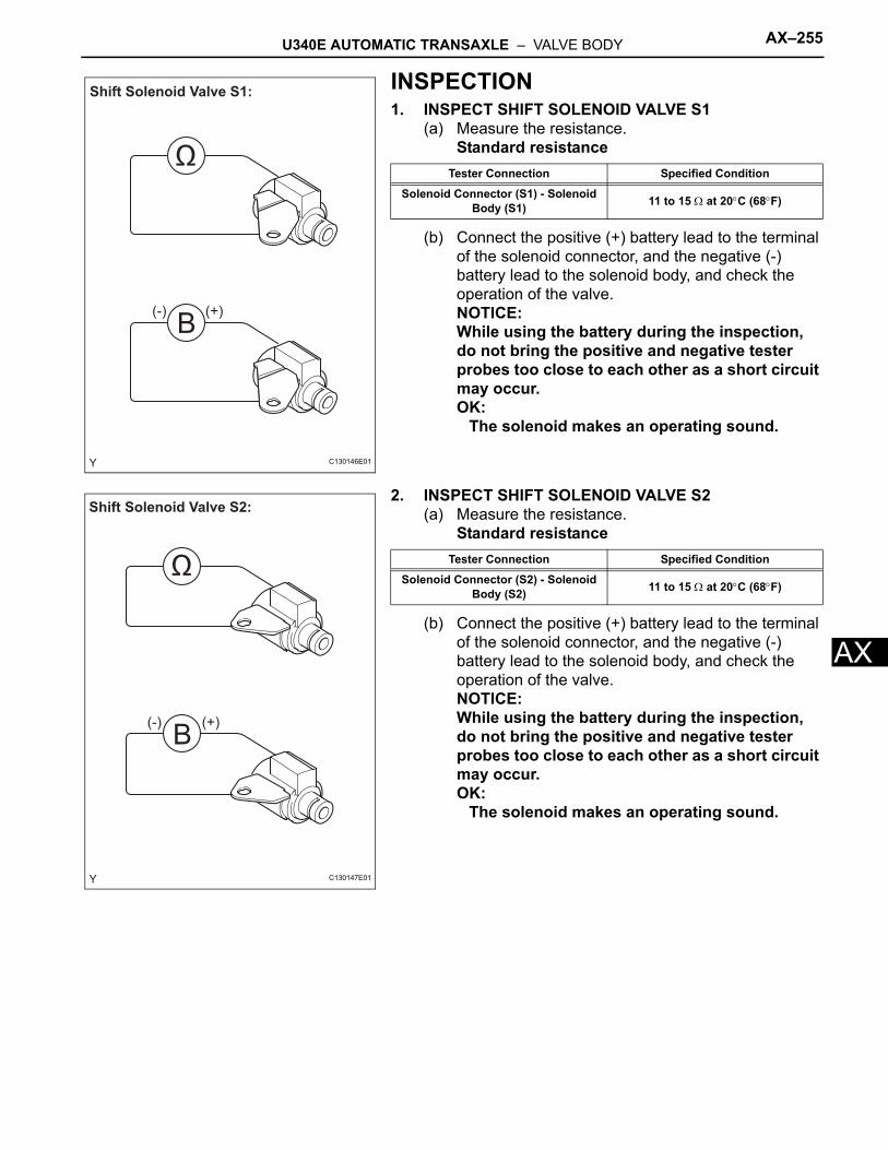
U340E AUTOMATIC TRANSAXLE – VALVE BODY AX–255
X
AINSPECTION1. INSPECT SHIFT SOLENOID VALVE S1
(a) Measure the resistance.Standard resistance
(b) Connect the positive (+) battery lead to the terminal of the solenoid connector, and the negative (-) battery lead to the solenoid body, and check the operation of the valve.NOTICE:While using the battery during the inspection, do not bring the positive and negative tester probes too close to each other as a short circuit may occur.OK:
The solenoid makes an operating sound.
2. INSPECT SHIFT SOLENOID VALVE S2(a) Measure the resistance.
Standard resistance
(b) Connect the positive (+) battery lead to the terminal of the solenoid connector, and the negative (-) battery lead to the solenoid body, and check the operation of the valve.NOTICE:While using the battery during the inspection, do not bring the positive and negative tester probes too close to each other as a short circuit may occur.OK:
The solenoid makes an operating sound.
B
Ω
Shift Solenoid Valve S1:
(-) (+)
C130146E01
Tester Connection Specified Condition
Solenoid Connector (S1) - Solenoid Body (S1) 11 to 15 Ω at 20°C (68°F)
B
Ω
Shift Solenoid Valve S2:
(-) (+)
C130147E01
Tester Connection Specified Condition
Solenoid Connector (S2) - Solenoid Body (S2) 11 to 15 Ω at 20°C (68°F)
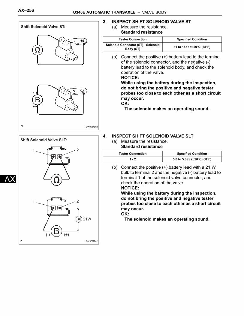
AX–256 U340E AUTOMATIC TRANSAXLE – VALVE BODY
AX
3. INSPECT SHIFT SOLENOID VALVE ST(a) Measure the resistance.
Standard resistance
(b) Connect the positive (+) battery lead to the terminal of the solenoid connector, and the negative (-) battery lead to the solenoid body, and check the operation of the valve.NOTICE:While using the battery during the inspection, do not bring the positive and negative tester probes too close to each other as a short circuit may occur.OK:
The solenoid makes an operating sound.
4. INSPECT SHIFT SOLENOID VALVE SLT(a) Measure the resistance.
Standard resistance
(b) Connect the positive (+) battery lead with a 21 W bulb to terminal 2 and the negative (-) battery lead to terminal 1 of the solenoid valve connector, and check the operation of the valve.NOTICE:While using the battery during the inspection, do not bring the positive and negative tester probes too close to each other as a short circuit may occur.OK:
The solenoid makes an operating sound.
Shift Solenoid Valve ST:
D009034E02
Tester Connection Specified Condition
Solenoid Connector (ST) - Solenoid Body (ST) 11 to 15 Ω at 20°C (68°F)
Shift Solenoid Valve SLT:
(-) (+)
21W
1 2
1 2
G020767E42
Tester Connection Specified Condition
1 - 2 5.0 to 5.6 Ω at 20°C (68°F)
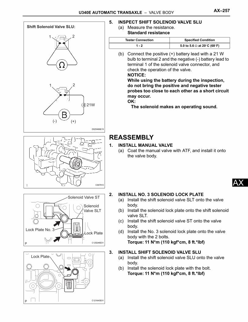
U340E AUTOMATIC TRANSAXLE – VALVE BODY AX–257
X
A5. INSPECT SHIFT SOLENOID VALVE SLU(a) Measure the resistance.
Standard resistance
(b) Connect the positive (+) battery lead with a 21 W bulb to terminal 2 and the negative (-) battery lead to terminal 1 of the solenoid valve connector, and check the operation of the valve.NOTICE:While using the battery during the inspection, do not bring the positive and negative tester probes too close to each other as a short circuit may occur.OK:
The solenoid makes an operating sound.
REASSEMBLY1. INSTALL MANUAL VALVE
(a) Coat the manual valve with ATF, and install it onto the valve body.
2. INSTALL NO. 3 SOLENOID LOCK PLATE(a) Install the shift solenoid valve SLT onto the valve
body.(b) Install the solenoid lock plate onto the shift solenoid
valve SLT.(c) Install the shift solenoid valve ST onto the valve
body.(d) Install the No. 3 solenoid lock plate onto the valve
body with the 2 bolts.Torque: 11 N*m (110 kgf*cm, 8 ft.*lbf)
3. INSTALL SHIFT SOLENOID VALVE SLU(a) Install the shift solenoid valve SLU onto the valve
body.(b) Install the solenoid lock plate with the bolt.
Torque: 11 N*m (110 kgf*cm, 8 ft.*lbf)
Shift Solenoid Valve SLU:
1 2
(-) (+)
1 2
21W
D025466E19
Tester Connection Specified Condition
1 - 2 5.0 to 5.6 Ω at 20°C (68°F)
C067910
Lock Plate No. 3Lock Plate
Solenoid
Valve SLT
Solenoid Valve ST
C125246E01
Lock Plate
C121643E01
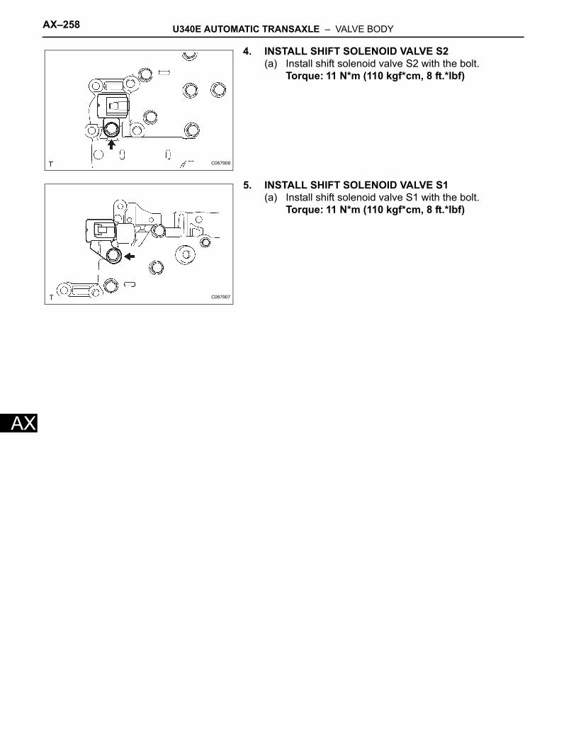
AX–258 U340E AUTOMATIC TRANSAXLE – VALVE BODY
AX
4. INSTALL SHIFT SOLENOID VALVE S2(a) Install shift solenoid valve S2 with the bolt.
Torque: 11 N*m (110 kgf*cm, 8 ft.*lbf)
5. INSTALL SHIFT SOLENOID VALVE S1(a) Install shift solenoid valve S1 with the bolt.
Torque: 11 N*m (110 kgf*cm, 8 ft.*lbf)
C067908
C067907
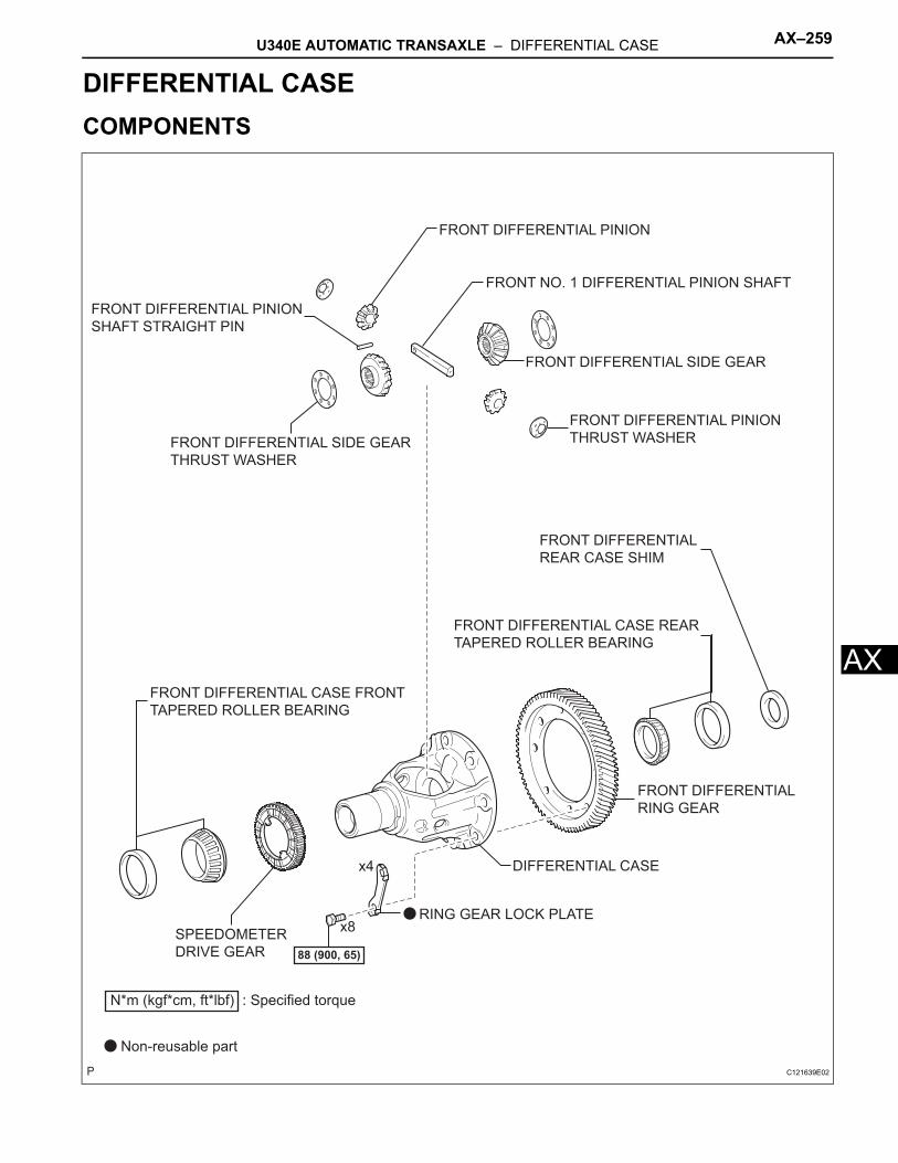
U340E AUTOMATIC TRANSAXLE – DIFFERENTIAL CASE AX–259
X
ATRANSMISSIONU340E AUTOMATIC TRANSAXLEDIFFERENTIAL CASECOMPONENTS
FRONT DIFFERENTIAL CASE FRONT
TAPERED ROLLER BEARING
FRONT DIFFERENTIAL CASE REAR
TAPERED ROLLER BEARING
FRONT DIFFERENTIAL PINION
SHAFT STRAIGHT PIN
FRONT DIFFERENTIAL
RING GEAR
FRONT DIFFERENTIAL SIDE GEAR
SPEEDOMETER
DRIVE GEAR
RING GEAR LOCK PLATE
DIFFERENTIAL CASE
88 (900, 65)
FRONT DIFFERENTIAL PINION
THRUST WASHERFRONT DIFFERENTIAL SIDE GEAR
THRUST WASHER
FRONT DIFFERENTIAL PINION
FRONT DIFFERENTIAL
REAR CASE SHIM
x4
x8
FRONT NO. 1 DIFFERENTIAL PINION SHAFT
N*m (kgf*cm, ft*lbf) : Specified torque
Non-reusable part
C121639E02
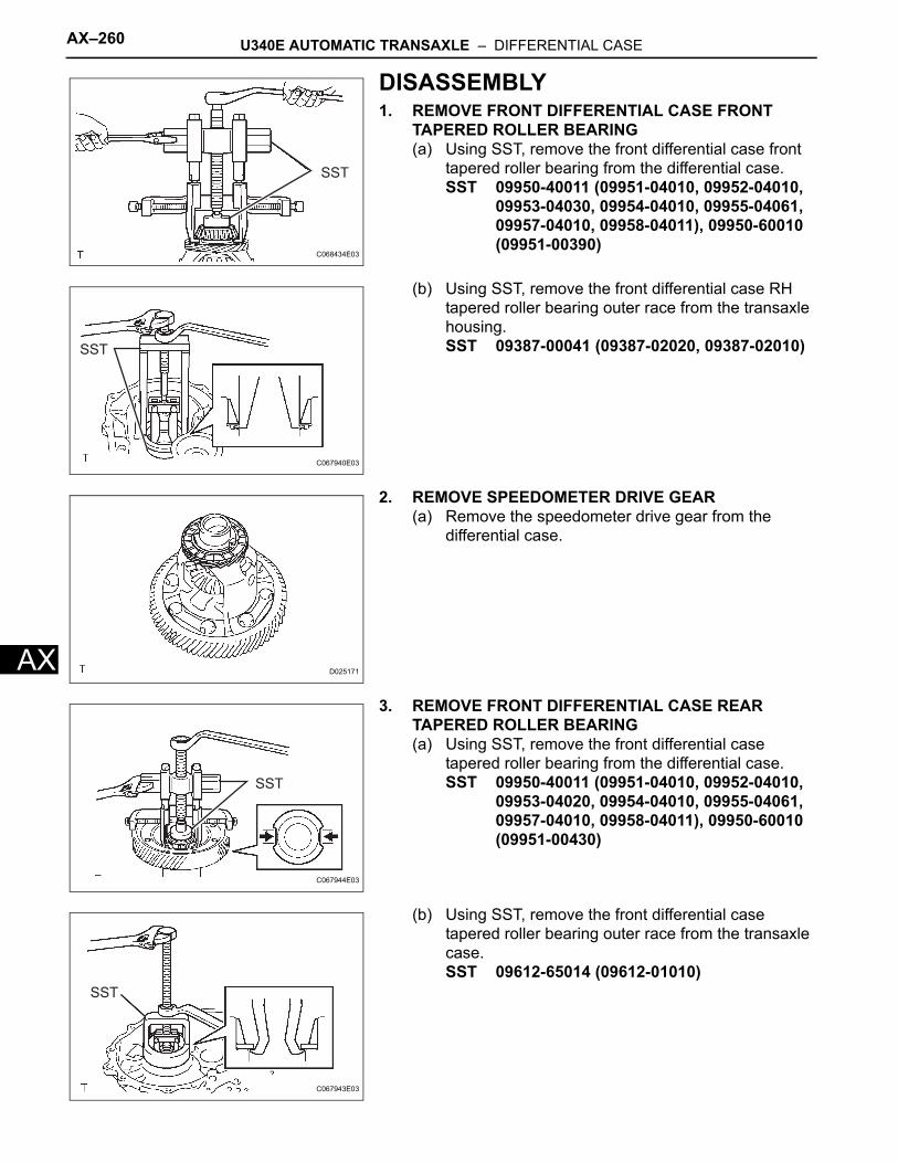
AX–260 U340E AUTOMATIC TRANSAXLE – DIFFERENTIAL CASE
AX
DISASSEMBLY1. REMOVE FRONT DIFFERENTIAL CASE FRONT
TAPERED ROLLER BEARING(a) Using SST, remove the front differential case front
tapered roller bearing from the differential case.SST 09950-40011 (09951-04010, 09952-04010,
09953-04030, 09954-04010, 09955-04061, 09957-04010, 09958-04011), 09950-60010 (09951-00390)
(b) Using SST, remove the front differential case RH tapered roller bearing outer race from the transaxle housing.SST 09387-00041 (09387-02020, 09387-02010)
2. REMOVE SPEEDOMETER DRIVE GEAR(a) Remove the speedometer drive gear from the
differential case.
3. REMOVE FRONT DIFFERENTIAL CASE REAR TAPERED ROLLER BEARING(a) Using SST, remove the front differential case
tapered roller bearing from the differential case.SST 09950-40011 (09951-04010, 09952-04010,
09953-04020, 09954-04010, 09955-04061, 09957-04010, 09958-04011), 09950-60010 (09951-00430)
(b) Using SST, remove the front differential case tapered roller bearing outer race from the transaxle case.SST 09612-65014 (09612-01010)
SST
C068434E03
SST
C067940E03
D025171
SST
C067944E03
SST
C067943E03
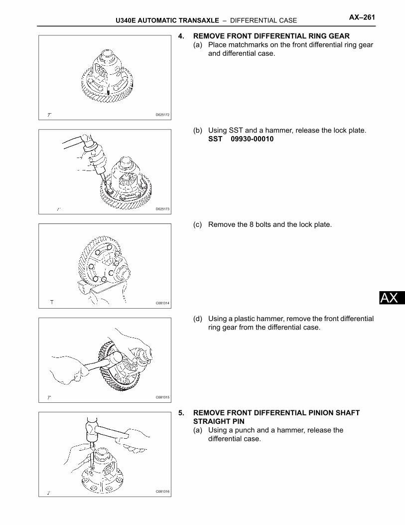
U340E AUTOMATIC TRANSAXLE – DIFFERENTIAL CASE AX–261
X
A4. REMOVE FRONT DIFFERENTIAL RING GEAR(a) Place matchmarks on the front differential ring gear
and differential case.
(b) Using SST and a hammer, release the lock plate.SST 09930-00010
(c) Remove the 8 bolts and the lock plate.
(d) Using a plastic hammer, remove the front differential ring gear from the differential case.
5. REMOVE FRONT DIFFERENTIAL PINION SHAFT STRAIGHT PIN(a) Using a punch and a hammer, release the
differential case.
D025172
D025173
C081314
C081315
C081316
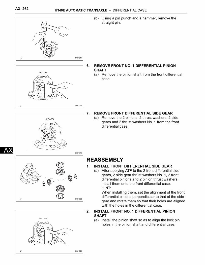
AX–262 U340E AUTOMATIC TRANSAXLE – DIFFERENTIAL CASE
AX
(b) Using a pin punch and a hammer, remove the straight pin.
6. REMOVE FRONT NO. 1 DIFFERENTIAL PINION SHAFT(a) Remove the pinion shaft from the front differential
case.
7. REMOVE FRONT DIFFERENTIAL SIDE GEAR(a) Remove the 2 pinions, 2 thrust washers, 2 side
gears and 2 thrust washers No. 1 from the front differential case.
REASSEMBLY1. INSTALL FRONT DIFFERENTIAL SIDE GEAR
(a) After applying ATF to the 2 front differential side gears, 2 side gear thrust washers No. 1, 2 front differential pinions and 2 pinion thrust washers, install them onto the front differential case.HINT:When installing them, set the alignment of the front differential pinions perpendicular to that of the side gear and rotate them so that their holes are aligned with the holes in the differential case.
2. INSTALL FRONT NO. 1 DIFFERENTIAL PINION SHAFT(a) Install the pinion shaft so as to align the lock pin
holes in the pinion shaft and differential case.
C081317
C081318
C081319
C081320
C081321
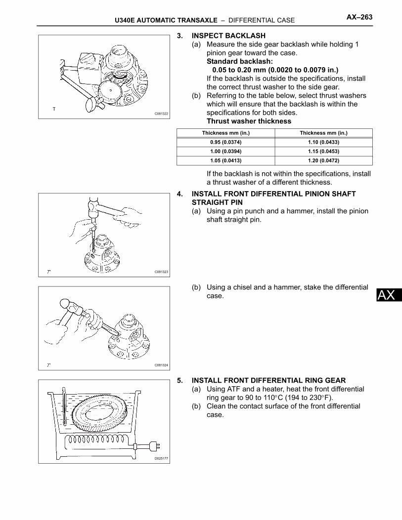
U340E AUTOMATIC TRANSAXLE – DIFFERENTIAL CASE AX–263
X
A3. INSPECT BACKLASH(a) Measure the side gear backlash while holding 1
pinion gear toward the case.Standard backlash:
0.05 to 0.20 mm (0.0020 to 0.0079 in.)If the backlash is outside the specifications, install the correct thrust washer to the side gear.
(b) Referring to the table below, select thrust washers which will ensure that the backlash is within the specifications for both sides.Thrust washer thickness
If the backlash is not within the specifications, install a thrust washer of a different thickness.
4. INSTALL FRONT DIFFERENTIAL PINION SHAFT STRAIGHT PIN(a) Using a pin punch and a hammer, install the pinion
shaft straight pin.
(b) Using a chisel and a hammer, stake the differential case.
5. INSTALL FRONT DIFFERENTIAL RING GEAR(a) Using ATF and a heater, heat the front differential
ring gear to 90 to 110°C (194 to 230°F).(b) Clean the contact surface of the front differential
case.
C081322
Thickness mm (in.) Thickness mm (in.)
0.95 (0.0374) 1.10 (0.0433)
1.00 (0.0394) 1.15 (0.0453)
1.05 (0.0413) 1.20 (0.0472)
C081323
C081324
D025177
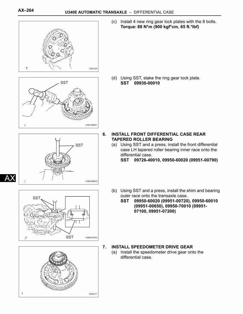
AX–264 U340E AUTOMATIC TRANSAXLE – DIFFERENTIAL CASE
AX
(c) Install 4 new ring gear lock plates with the 8 bolts.Torque: 88 N*m (900 kgf*cm, 65 ft.*lbf)
(d) Using SST, stake the ring gear lock plate.SST 09930-00010
6. INSTALL FRONT DIFFERENTIAL CASE REAR TAPERED ROLLER BEARING(a) Using SST and a press, install the front differential
case LH tapered roller bearing inner race onto the differential case.SST 09726-40010, 09950-60020 (09951-00790)
(b) Using SST and a press, install the shim and bearing outer race onto the transaxle case.SST 09950-60020 (09951-00720), 09950-60010
(09951-00650), 09950-70010 (09951-07100, 09951-07200)
7. INSTALL SPEEDOMETER DRIVE GEAR(a) Install the speedometer drive gear onto the
differential case.
C081325
SST
C081326E01
SST
C068169E03
SST
SST
C068191E03
D025171
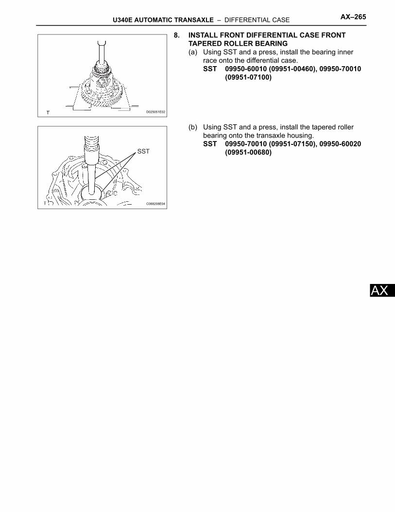
U340E AUTOMATIC TRANSAXLE – DIFFERENTIAL CASE AX–265
X
A8. INSTALL FRONT DIFFERENTIAL CASE FRONT TAPERED ROLLER BEARING(a) Using SST and a press, install the bearing inner
race onto the differential case.SST 09950-60010 (09951-00460), 09950-70010
(09951-07100)
(b) Using SST and a press, install the tapered roller bearing onto the transaxle housing.SST 09950-70010 (09951-07150), 09950-60020
(09951-00680)
D025051E02
SST
C068208E04


![A960E AUTOMATIC TRANSMISSION · A960E AUTOMATIC TRANSMISSION GENERAL The A960E 6-speed automatic transmission [6 Super ECT (Electronic Controlled Transmission)] is used on the 4GR-FSE](https://img.pdfslide.us/doc/110x75/5e8ff69218b2bd4cae3aae4a/a960e-automatic-transmission-a960e-automatic-transmission-general-the-a960e-6-speed.jpg)