Embed Size (px)
Citation preview
Step-by-Step Guide to Using Your
In-Step Mobility Products Corp.
U-Step II Walking Stabilizer
4-inch non-markingcasters
Paddedseat
Tension control
Heightadjustable
Adjustablebackrest
Spring-loaded front wheel
Place to step forgoing up curbs
Glow-in-the-Darktabs
Laser module(Optional)
Laser projectedred line –optional
Ergonomicallypositionedhandlebars
Comfort grips
Hand brake
Removablebasket
www.ActiveForever.com
— 2 —
CONTENTS:
A. Assembly Instructions
B. Braking
C. Tension Control Adjustment
D. Sitting Down
E. Walking Over Obstacles
F. Transporting
G. Setup After Transporting
H. Accessories
1. Alternative Brake Accessory
2. Laser & Sound Cueing Module
3. Replacing the Cueing Module Batteries
4. Optional Weights
I. Maintenance
J. Warranty Information
Guide for Setting Up & Using Your U-Step II
www.ActiveForever.com
1) After opening the box, cut the plastic ties that secured the U-Step II in transit.
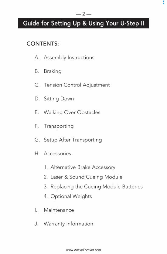
2) Attach the basket to theU-Step II. The back of thebasket has a mounting platethat connects to the hard-ware on the back of the junc-tion. (See Right)
a. First remove the two wingnuts and washers on the toptwo bolts.
b. Undo the two Velcrostraps holding the mesh intothe rear of the basket.
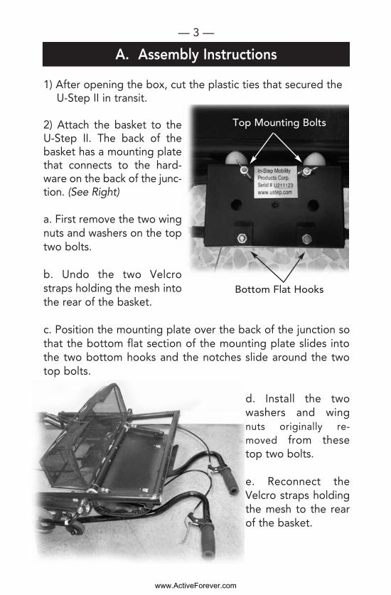
c. Position the mounting plate over the back of the junction sothat the bottom flat section of the mounting plate slides intothe two bottom hooks and the notches slide around the twotop bolts.
d. Install the twowashers and wingnuts originally re-moved from thesetop two bolts.
e. Reconnect theVelcro straps holdingthe mesh to the rearof the basket.
— 3 —
A. Assembly Instructions
Bottom Flat Hooks
Top Mounting Bolts
www.ActiveForever.com
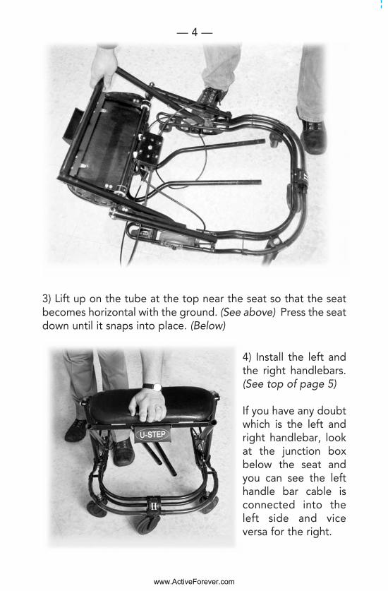
3) Lift up on the tube at the top near the seat so that the seatbecomes horizontal with the ground. (See above) Press the seatdown until it snaps into place. (Below)
4) Install the left andthe right handlebars.(See top of page 5)
If you have any doubtwhich is the left andright handlebar, lookat the junction boxbelow the seat andyou can see the lefthandle bar cable isconnected into theleft side and viceversa for the right.
— 4 —
www.ActiveForever.com
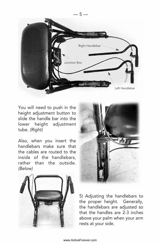
You will need to push in theheight adjustment button toslide the handle bar into thelower height adjustmenttube. (Right)
Also, when you insert thehandlebars make sure thatthe cables are routed to theinside of the handlebars,rather than the outside.(Below)
5) Adjusting the handlebars tothe proper height. Generally,the handlebars are adjusted sothat the handles are 2-3 inchesabove your palm when your armrests at your side.
— 5 —
Junction Box
Right Handlebar
Left Handlebar
www.ActiveForever.com
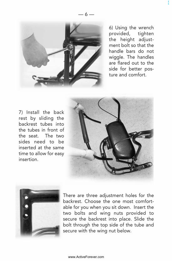
6) Using the wrenchprovided, tightenthe height adjust-ment bolt so that thehandle bars do notwiggle. The handlesare flared out to theside for better pos-ture and comfort.
7) Install the backrest by sliding thebackrest tubes intothe tubes in front ofthe seat. The twosides need to beinserted at the sametime to allow for easyinsertion.
There are three adjustment holes for thebackrest. Choose the one most comfort-able for you when you sit down. Insert thetwo bolts and wing nuts provided tosecure the backrest into place. Slide thebolt through the top side of the tube andsecure with the wing nut below.
— 6 —
www.ActiveForever.com
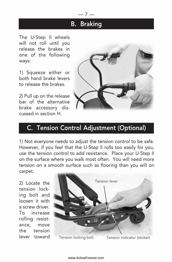
The U-Step II wheelswill not roll until yourelease the brakes inone of the followingways:
1) Squeeze either orboth hand brake leversto release the brakes.
2) Pull up on the releasebar of the alternativebrake accessory dis-cussed in section H.
1) Not everyone needs to adjust the tension control to be safe.However, if you feel that the U-Step II rolls too easily for you,use the tension control to add resistance. Place your U-Step IIon the surface where you walk most often. You will need moretension on a smooth surface such as flooring than you will oncarpet.
2) Locate thetension lock-ing bolt andloosen it witha screw driver.To increaserolling resist-ance, movethe tensionlever toward
— 7 —
B. Braking
C. Tension Control Adjustment (Optional)
Tension locking bolt
Tension lever
Tension indicator (sticker)
www.ActiveForever.com

the front of the walker. On the frame just below the tensionlever is an indicator for adjusting the tension lever. “H” standsfor Higher tension and “L” stands for Lower tension.
3) Re-tighten thetension locking boltto hold the positionof the tension lever.
4) Remember tosqueeze one of thehand brakes whiletesting the walker.Test the rollingspeed of the walker;if you need more orless resistance adjustaccordingly.
To sit down, you can either turnaround while holding the han-dlebar, or pivot the U-Step IIaround so that it is positionedbehind you and then sit downon the seat.
When you are sitting on the U-Step II you are facing back-wards relative to the movingdirection of the U-Step II.
— 8 —
j WARNING:While sitting, DO NOT pushoff with your feet to move the U-Step II. This is unsafe.
D. Sitting Down
www.ActiveForever.com
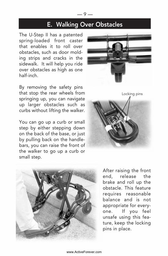
The U-Step II has a patentedspring-loaded front casterthat enables it to roll overobstacles, such as door mold-ing strips and cracks in thesidewalk. It will help you rideover obstacles as high as onehalf-inch.
By removing the safety pinsthat stop the rear wheels fromspringing up, you can navigateup larger obstacles such ascurbs without lifting the walker.
You can go up a curb or smallstep by either stepping downon the back of the base, or justby pulling back on the handle-bars, you can raise the front ofthe walker to go up a curb orsmall step.
After raising the frontend, release thebrake and roll up theobstacle. This featurerequires reasonablebalance and is notappropriate for every-one. If you feelunsafe using this fea-ture, keep the lockingpins in place.
— 9 —
E. Walking Over Obstacles
Locking pins
www.ActiveForever.com

1) With the U-Step IIin front of you, raisethe release lever infront of the seat andtilt the seat upward.
2) Reach down andpull up on the hori-zontal bar that has asticker on it reading“Lift Here to Fold”until the U-Step IIfolds up.
— 10 —
F. Transporting Your U-Step II
Release Lever
www.ActiveForever.com
— 11 —
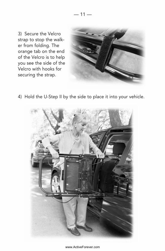
3) Secure the Velcrostrap to stop the walk-er from folding. Theorange tab on the endof the Velcro is to helpyou see the side of theVelcro with hooks forsecuring the strap.
4) Hold the U-Step II by the side to place it into your vehicle.
www.ActiveForever.com
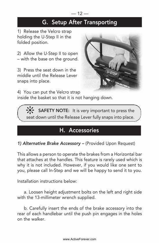
1) Release the Velcro strapholding the U-Step II in thefolded position.
2) Allow the U-Step II to open– with the base on the ground.
3) Press the seat down in themiddle until the Release Leversnaps into place.
4) You can put the Velcro strapinside the basket so that it is not hanging down.
1) Alternative Brake Accessory – (Provided Upon Request)
This allows a person to operate the brakes from a Horizontal barthat attaches at the handles. This feature is rarely used which iswhy it is not included. However, if you would like one sent toyou, please call In-Step and we will be happy to send it to you.
Installation instructions below:
a. Loosen height adjustment bolts on the left and right sidewith the 13-millimeter wrench supplied.
b. Carefully insert the ends of the brake accessory into therear of each handlebar until the push pin engages in the holeson the walker.
— 12 —
H. Accessories
G. Setup After Transporting
j SAFETY NOTE: It is very important to press theseat down until the Release Lever fully snaps into place.
www.ActiveForever.com

c. Adjust the height of thehandlebars so that the hori-zontal bar is at a comfortableheight for you.
d. Re-tighten the heightadjustment bolts.
e. The pull-up rod below should be positioned below thehand brakes so that when the rod is pulled up the hand brakesare squeezed.
f. If you use this Alternative Brake setup, you may want toremove the backrest in front so that you can sit down on yourU-Step II from the front.
2) Laser and Sound Cueing Module —
Primarily used by those with Parkinson’s freezing but can beused by anyone with an irregular gait pattern. The Laser andSound Cueing Module can help you get started, normalize yourwalking, and increase your stride. First press the red button onthe module that is located below the seat. This will activate theLaser cueing function. A bright red laser line will be projectedon the floor to guide your steps.
To activate the Sound Cueing, press and hold the top blackbutton in for a few seconds. You will then hear the beeping. Toset the beep pattern to befaster, press the top blackbutton. To slow down thebeep pattern, press the bot-tom black button.
The sound cueing will onlywork when the laser cueingis on. To turn it off, you need
— 13 —
www.ActiveForever.com
to press the red button and turn off the whole unit. Thelaser will go off automatically if you forget to turn it off. Toadjust how long the laser stays on without turning it off,press the red button to turn on the unit and then press thetop black button. Each short beep signifies 4 minutes. Tochange the volume of the beeps, press the red button toturn on the unit and then press the bottom black buttonuntil you get to volume desired.
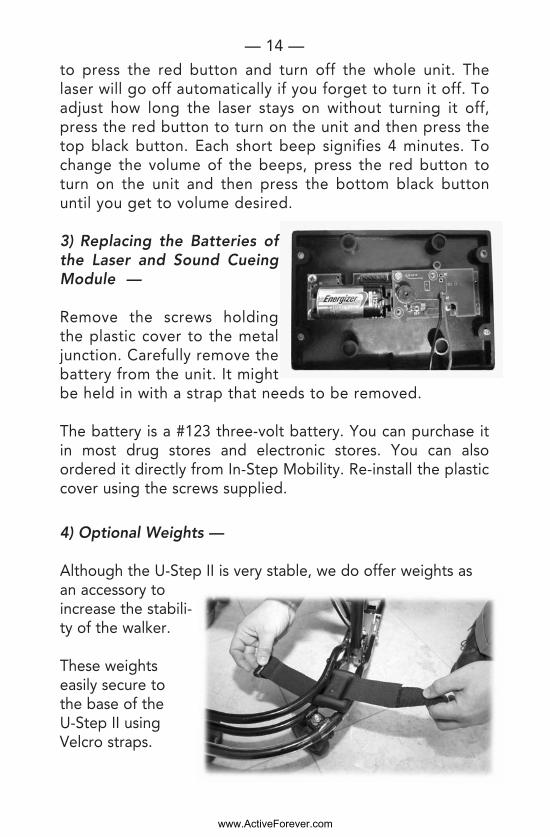
3) Replacing the Batteries ofthe Laser and Sound CueingModule —
Remove the screws holdingthe plastic cover to the metaljunction. Carefully remove thebattery from the unit. It mightbe held in with a strap that needs to be removed.
The battery is a #123 three-volt battery. You can purchase itin most drug stores and electronic stores. You can alsoordered it directly from In-Step Mobility. Re-install the plasticcover using the screws supplied.
4) Optional Weights —
Although the U-Step II is very stable, we do offer weights asan accessory toincrease the stabili-ty of the walker.
These weights easily secure to the base of the U-Step II usingVelcro straps.
— 14 —
www.ActiveForever.com
I. Maintenance
J. Warranty
j NOTE: DO NOT pull on the cabling. Pulling on acable can cause it to become kinked or stretched outof shape, which could prevent the braking systemfrom functioning properly. A damaged cable shouldbe replaced. Please have your U-Step II serviced ifthe cabling becomes damaged.
Your U-Step II Walking Stabilizer is warranted for a full year towork properly and be free from any defects in materials andworkmanship. Additionally, the frame is warranted for threeyears from the date of purchase.
In the event of a defect covered by this warranty, we will, at ouroption, repair or replace the device. In the event of a problem,you will need to return the walker for repair at your cost. We willfix the product or replace it and send it back to you at our cost.
This warranty does not cover device failure due to owner's mis-use or negligence.
In the event of a minor problem, In-Step Mobility Products willattempt to resolve the issue by sending replacement parts.
If you have a question about your U-Step II or this warranty,please contact In-Step Mobility Products at 1-800-558-7837.
— 15 —
Clean your U-Step II with a clean, damp cloth when necessary.
Periodically check some of the moving components for wear.On a daily basis, check over the U-Step II by trying the brakes.Please call your U-Step II representative or call 1-800-558-7837if you experience any problems with the tension of the wheelsor with braking.
www.ActiveForever.com
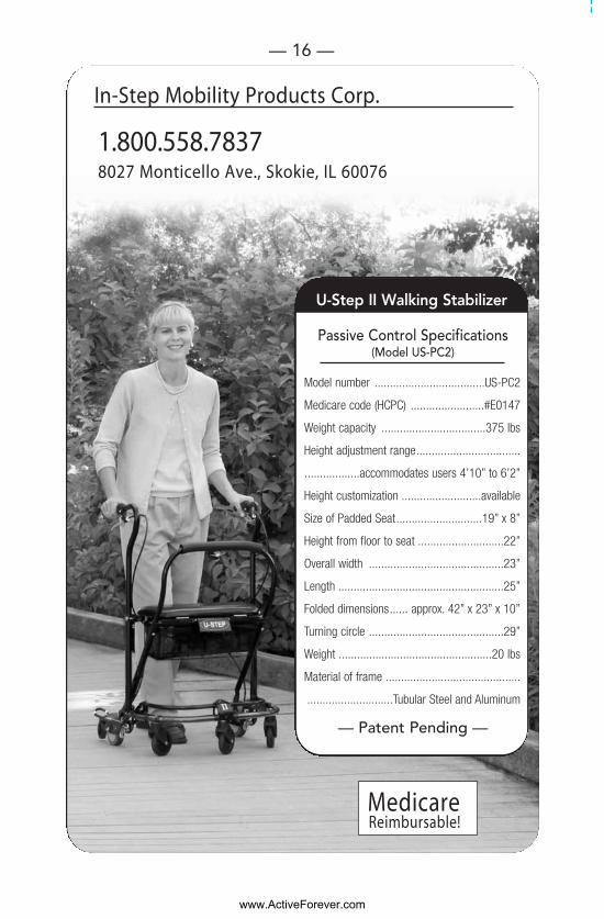
U-Step II Walking Stabilizer
MedicareReimbursable!
In-Step Mobility Products Corp.
8027 Monticello Ave., Skokie, IL 60076 1.800.558.7837
— 16 —
Passive Control Specifications(Model US-PC2)
Model number ....................................US-PC2
Medicare code (HCPC) ........................#E0147
Weight capacity ..................................375 lbs
Height adjustment range..................................
..................accommodates users 4’10” to 6’2”
Height customization ..........................available
Size of Padded Seat............................19” x 8”
Height from floor to seat ............................22”
Overall width ............................................23”
Length ......................................................25”
Folded dimensions...... approx. 42” x 23” x 10”
Turning circle ............................................29”
Weight ..................................................20 lbs
Material of frame ............................................
............................Tubular Steel and Aluminum
— Patent Pending —
www.ActiveForever.com