Embed Size (px)
Citation preview
Type covered in this manual
• UAN Type : UAN06, UAN08, UAN10, UAN12,
UAN16, UAN20, UAN25, UAN32,
UAN40, UAN50
• UAS Type : UAS06, UAS08, UAS10, UAS12,
UAS16, UAS20, UAS25, UAS32
Notice
• Read this instruction manual carefully before
using this Air Circuit Breaker.
• This instruction manual does not include all
information regarding installation and
maintenance.
• For further information, please contact
Hyundai Heavy Industries (HHI) or your local
dealer.
U-Series
Air Circuit BreakersInstruction Manual

| U-Series | Air Circuit Breakers Instruction Manual
Safety Practices
This instruction manual applies only to U-Series air circuit breakers (ACB) regarding installation and maintenance procedures.
Installing and maintaining these products improperly may result in serious personal injury, property damage, or even death.
Therefore this instruction manual must be read and understood at any step in unpacking, assembly, operation, and maintenance of
the breaker. Only qualified persons who are familiar with installing and maintaining circuit breakers are permitted to work on breakers,
and this instruction manual should be accessible to those persons at any time.
For Operational Safety of Air Circuit Breakers
Indicates an imminently hazardous point that, if ignored, a serious accident causing death or severe injury could occur.
This is the most dangerous point.
Indicates a potentially hazardous point that, if ignored, a serious accident causing death or severe injury could occur.
Indicates a potentially hazardous point that, if ignored, minor or moderate injury could occur.
This signal reminds operators to work safely.
Never lift the ACB over an area where there are people.
Naver stand under the ACB.
• OCR field tests and setting changes must be performed by qualified personnel.
• After completion of OCR tests, make sure to return the original values.
• Failure to do may cause a fire or burnout.
• If the ACB trips open automatically, remove the cause before closing the ACB.
Otherwise, a fire could occur.
• For the ACB with the fixing block, be sure to loosen the block screws before drawing out the ACB.
Otherwise, damage to the ACB may occur.
• Never touch live terminal parts.
There is a risk of electric shock.
• Do not leave the ACB in the draw-out position.
Dropping the ACB cause serious injury.
Signal Words
Signal words used in this instruction manual are divided by DANGER, WARNING, and CAUTION depending on the situation.
Transportation Precaution
OCR Field Test Precautions
Operation Precautions
CAUTION
DANGER
DANGER
CAUTION
CAUTION
DANGER
WARNING

2 | 3
• Installation work must be performed by qualified personnel.
• Prior to commencing any installation work, open an upstream circuit breaker to shut off all sources of power.
Otherwise, electric shock may occur.
• Tighten terminal bolt up securely to the specified torque.
Otherwise, a fire may occur.
• Fix the draw-out cradle of the ACB firmly on a flat level surface using mounting screws.
Otherwise, draw-out operation may cause the ACB to fall.
• To ensure adequate arc space (insulation distance), avoid blocking the arc gas vents of the ACB.
Otherwise a burn may result from high temperature arc gas.
• Do not place the ACB in such as an area that is subject to high temperature, high humidity, dusty air,
corrosive gas, vibration and shock, or other unusual conditions.
Mounting in such area could cause a fire, non-tripping, or malfunction.
• Install the ACB to prevent dust, concrete powder, iron powder, and rainwater from entering the unit.
These materials could cause a fire or non-tripping.
• For the ACB with four poles, connect the neutral wire of a 3-phase, 4-wire cable to the N-phase pole
(on the right end).
Otherwise, an overcurrent may cause non-tripping resulting a fire.
• ACB maintenance, inspection and/or parts replacement must be performed by qualified personnel.
• Prior to commencing any work on the ACB, open an upstream breaker or the like to isolate all sources of
power/voltage from both the primary and auxiliary circuits.
Otherwise, electric shock may result.
• Prior to commencing ACB internal inspection, make sure that the ACB is open and the closing spring is released.
Otherwise, fingers or tools could be pinched in the internal mechanism, resulting injury.
• Retighten the terminal screws periodically to the specified torque.
Otherwise, a fire could result.
• Be sure to reinstall the arc chamber if removed.
Failure to do so or incorrect installation of the arc chamber may result in a fire or burn.
• Do not touch ACB live parts (contacts in particular), or structural parts close to a live part immediately
after opening the ACB to stop supplying power.
Otherwise, remaining heat may cause burn or residual charged voltage may cause electric shock.
• Do not bring your hand or face close to the arc gas vent of the arc chute while the ACB is closed.
Otherwise, a burn may result from high-temperature arc gas blowing out of the arc gas vent
when the ACB trips open.
Installation Precautions
Maintenance and Inspection Precautions
CAUTION
CAUTION

| U-Series | Air Circuit Breakers Instruction Manual
1. Receiving and Handling
1.1 Storage 5
1.2 Transportation 5
1.3 Installation 5
2. Structure 7
3. Operation
3.1 Manual Charging Type 8
3.2 Motor Charging Type 9
4. Draw-out Mechanism 10
4.1 Draw-out Operation 11
4.2 Draw-in Operation 13
5. Periodic Inspection and Parts Replacement 14
5.1 Arc Chamber 15
5.2 Contact Unit 16
5.3 Operating Mechanism 17
5.4 Internal Accessories 18
6. Protection Relay-UPR 24
6.1 Rated Current 26
6.2 Protective Functions and Setting Ranges 26
6.3 Operation Indication Functions 29
6.4 Field Test 30
6.5 Characteristic Check 32
6.6 Operating Manual for UPR-LA, LAG, LAZ, LP, LH, SA, SP Type 35
7. Insulation Resistance Test and Dielectric Withstand Test
7.1 Main Circuit 41
7.2 Control Circuit (to earth) 41
8. Troubleshooting Points 42
9. Appendix
9.1 Neutral CT and UPR Protection Relay Connection Methods 43
9.2 Ground Protection Method 44
9.3 Closing and Trip Operation Cycle 45
9.4 Wiring Circuit for UPR Protection Relay 46
9.5 Wiring Circuit for ACB 50
Contents

01 Receiving and Handling
Upon receipt of your breaker, check the following first.
HHI air circuit breakers are completely assembled, inspected and tested both electrically and mechanically at the factory, then
shipped in fully guaranteed condition in construction and operation.
1.2 Transportation
When transporting the breaker, follow these instructions.
1) When lifting up the breaker, suspend wire rope from lifting lug and take care to ensure that the wire ropes do not touch
the arc chute and protection relay. When lifting up the breaker, be sure to lift it up slowly.
2) Lower the breaker onto a flat surface.
3) Avoid impacts and shocks to the breaker during transportation.
1.3 Installation
1) Ambient temperature : from -5 C̊ to +40 C̊ (24 hours average temperature should not exceed 35 C̊).
2) Altitude : Less than 2,000 m
3) In case of special environment application
(1) Derating table for the altitude over 2,000 m
Altitude ≤2,000 m 3,000 m 4,000 m 5,000 m
Rated voltage 690 V 590 V 520 V 460 V
Rated current 100 % 99 % 96 % 94 %
(2) Derating table for ambient temperature over 40 C̊
Ambient Temperature ≤40 C̊ 50 C̊ 60 C̊
Rated current 100 % 95 % 90 %
1.1 Storage
While it is recommended that the breaker be used as soon as you have received it. If it is necessary to store the ACB, note the
followings.
1) Store the breaker in a dry indoor location to prevent condensation due to sudden changes in ambient temperature,
which is quite harmful to the breaker insulation.
2) Store the breaker in a clean place free of corrosive gases, dirt, dust and salinity (NaCI).
In particular, a mixture of cement dust and moisture may cause corrosion damage to metal parts of the ACB.
Fully protect the breaker from such mixtures.
3) Place the breaker on a flat, level surface in its normal position.
4) Do not place the breaker directly on the floor.
5) Do not stack up ACBs.
4 | 5

| U-Series | Air Circuit Breakers Instruction Manual
(3) Clearance requirements
※ - In case of arc shield application, ignore "A" size.
- In case of mechanical interlock application, it needs extra space over "B" size.
B B
A
01 Receiving and Handling
Minimum Space Distance A B
Insulate parts 150 mm 30 mm
Metal parts 150 mm 50 mm

Fig. 1
1 Control circuit terminal
2 Front cover
3 Close/Open indicator
4 Close button
5 Protection relay (UPR)
6 Open button
7 Position padlock
8 Position lock release button
9 Draw-in/out handle insertion hole
10 Position indicator
11 Cycle counter
12 Charged/Discharged indicator
13 Charging handle
14 Name plate
15 Arc shield
16 Busbar terminal
17 OCR Manual reset
18 Draw-out guide rail
02 Structure
1
2
17
3
4
5
6
7
8
9
10
11
12
13
14
18
Cradle for vertical type busbar Cradle for horizontal type busbar
15
16
6 | 7

| U-Series | Air Circuit Breakers Instruction Manual
1
3
2
54
2
1
03 Operation
3.1 Manual Charging Type
In the manual charging type, both charging the closing springs and open-close control of the breaker should be done manually.
The breaker is able to close only when the closing spring is charged.
1) Spring charging operation
Follow the procedure given below to charge the closing springs.
• Pump the charging handle (Fig. 2. ①) about five times.
• When closing springs are fully charged, a metallic click will be heard and no more pumping of the charging handle will be possible.
Check that the spring charged indicator now shows「 」(Fig. 2. ②).
2) Closing operation
Check the instruction before closing the breaker.
• Closing spring should be charged.
• Position lock release button should be in original position (Fig. 3. ①).
• Specified voltage should be applied to the under-voltage trip device option.
See the description of the under-voltage trip device for the procedure in detail.
Upon satisfactory confirmation of the above three items, press the closing button (Fig. 3. ②).
Then, closing springs are discharged and the breaker is closed.
The close/open indicator indicates「 」and spring charged indicator shows「 」(Fig. 3. ③).
3) Opening operation
Press the open button (Fig. 3. ④), close/open indicator indicates「 」(Fig. 3. ⑤).
Air circuit breakers are available either manual charging type or motor charging type.
Do not force down the charging handle after completion of charging.
It may cause a malfunction.
CAUTION
Fig. 2 Fig. 3

3.2 Motor Charging Type
In this type, a motor-operated mechanism automatically charges the closing springs.
Means for remote electrical close-open control of the breaker are also fitted (see page 50-51 wiring circuit).
Manual operation is also possible (manual operation procedures are described in the 3.1 section manual charging type).
1) Spring charging operation
• Supply the specified control power voltage to the charging motor circuit.
• As soon as the closing springs are discharged, the charging motor is turned on to charge the closing springs.
• The charging motor is automatically stopped after the closing springs are fully charged.
Then, charged/discharged indicator show charged sign,「 」(Fig. 2. ②).
Spring charging time is different according to control power and type of breaker.
This is normally within a range of 3 to 10 seconds.
2) Closing operation
Before closing the breaker, check the followings.
• Closing springs are charged.
• Position lock release button should be in original position.
• Under voltage trip device (UVT) is supplying rated voltage.
Upon satisfactory confirmation of the above items, press the PB (Close) button (page 50-51).
This energizes LRC (latch release coil, Fig. 9. ④) which in turn release the closing springs and close the breaker.
Close/Open indicator indicates [ ] (Fig. 3. ③).
Charged/Discharged indicator indicates「 」(Fig. 3. ③).
When closing springs are discharged, the charging motor immediately turn to charge closing springs.
3) Opening operation
The shunt trip device (SHT) or under voltage trip device (UVT) is used for remote electrical opening operation.
Press the open button (PB open, page 50-51). This opens the breaker via the SHT or UVT.
The permissible control voltage range for the charging motor is from 85 % to 110 % but 100 % of rated voltage
is more recommended to be supplied.
Failure to follow this instruction will result damage in charging motor.
CAUTION
It is strongly recommended to supply the control power at the rated voltage.
Dielectric withstand test in motor, AC/DC 100-220 V : 1,500 V 1 min, DC 24, 48 V : 500 V 1 min.
The motor jack should be disconnected before dielectric withstand test.
CAUTION
When close-open operations are repeated with the charging motor ON, limit the number of successive close-open cycles to
10 times. If the open-close cycle is repeated more than 10 times, allow a cooling period of at least 10 minutes between
the 10th cycle and the 11th cycle.
Repeating open-close cycle more than 10 times consecutively may damage of charging motor.
CAUTION
Even when no. 2) is not satisfied, the breaker will not be placed in a closed state.
Be sure to perform closing operation according no. 2).
CAUTION
8 | 9

| U-Series | Air Circuit Breakers Instruction Manual
Caution of operation
- Open the breaker before working with the draw-out mechanism.
- Loosen the screws of the fixing blocks before drawing out the breaker body.
- Push the position lock release button (Fig. 1. ⑧), insert draw-in/out handle into the insertion hole (Fig. 1. ⑨).
- When you try to move the breaker body to the CONNECTED position, the operating force will increase.
Torque of operating force is about 25 kgf.
- Operate draw-in/out handle totally in inserted state.
- Rotate draw-in/out handle until the handle is locked automatically at each ISOLATED, TEST, and CONNECTED position.
At each locked position, stop turning the draw-out handle.
Failure to follow this instruction can result in equiptment damage or malfunction.
Main circuit connected Control connected
Main circuit connected Control connected
Main circuit connected Control connected
ISOLATED position
CONNECTED position TEST position
REMOVED position
04 Draw-out Mechanism
In order to test the breaker and exchange parts easily, the breaker body is drawn-in/out from draw-out cradle, the breaker can be
fixed in one among three of draw-out cradle.
The breaker can be moved to TEST or ISOLATED position when the panel door is closed.
During the breaker body move from ISOLATED to CONNECTED position, or from CONNECTED to ISOLATED position,
do not rotate the handle by releasing position locking.
CAUTION

1
2
3
4
7
5
6
4.1 Draw-out Operation
The draw-in/out handle is used to move the breaker body to one of the three positions (CONNECTED, TEST, ISOLATED).
When the fixing blocks (Fig. 4. ② option) are fitted, loosen the right and left screws of the fixing blocks before
drawing-out operation.
CAUTION
When the main circuit is disconnected as the breaker body is being drawn out, the breaker body will be slightly pushed
forward by the spring action of the primary disconnect contacts with a "banging" sound.
While the loudness of this sound may vary, the sound itself is perfectly normal and does not affect breaker performance.
CAUTION
When position lock release button (Fig. 4. ⑤) is pushed, the breaker will not close.
In order to test operation, must move to the right position (CONNECTED, TEST, ISOLATED), and position lock release button
(Fig. 4. ⑤) should be pushed out.
CAUTION
When breaker body is drawn out to the TEST position or ISOLATED position, a metallic sound "click" will be heard,
and the draw-in/out handle operation is automatically locked.
At this time, do not attempt to compulsively rotate the handle.
DANGER
1) Moving from CONNECTED position to TEST position
• When the fixing blocks are fitted, loosen and free right and left screws.
• Check that the breaker is open.
If it is closed, push open button (Fig. 4. ④) to open breaker.
• When the position lock release button is completely pushed in, connect draw-in/out handle to shaft fully.
If it is not completely pushed in or not inserted, the body doesn't move and indicator doesn't rotate.
The position indicator is rotated while the breaker body drawn out.
Fig. 4
10 | 11

| U-Series | Air Circuit Breakers Instruction Manual
Fig. 5
3
5
1
42
04 Draw-out Mechanism
2) Moving from TEST position to ISOLATED position
In order to move from TEST to ISOLATED, push position lock release button (Fig. 4. ⑤) shortly after handle locking is released,
and turn the draw-in/out handle in a counterclockwise direction.
3) Removing body from ISOLATED position
For maintenance, inspection, or exchanging parts, the breaker in the ISOLATED position should be drawn out from the draw-out
cradle. If the breaker is charged, the breaker should release the closing springs, by using the manual close and open button.
• When the breaker is drawn-out perfectly, the breaker body is stopped by rail end stoppers (Fig. 5. ④).
To release the stoppers, pull down the body lock (Fig. 5. ④) and take out the body slowly.
If it is approaching ISOLATED position, draw-in/out handle (Fig. 4. ①) will be automatically locked.
Do not attempt to compulsively rotate the handle.
CAUTION
This operation should be done slowly.
Apply wire rope to the lifting lug and lift the body upward after releasing stoppers.
CAUTION
Don't leave the breaker in REMOVED position.
When the breaker is drawn out, the center of gravity is changed.
The draw-out cradle should be fixed in advance in the PNL.
CAUTION

• With position lock release button (Fig. 4. ⑤) pushed, connect drawing in/out handle to the shaft.
• Then, when position lock release button (Fig. 4. ⑤) is pushed, it maintains self holding and allows draw-in/out handle (Fig. 4. ①)
operation.
• To move the breaker to CONNECTED or TEST position, rotate draw-in/out handle in a clockwise direction.
With the breaker moving, if position indicator is accessing TEST position, position release button (Fig. 4. ⑤) is automatically pushed
out and it locked draw-in/out handle.
When the handle is locked, do not rotate excessively. This may cause damage to the breaker.
• In the TEST position, with the handle stick, PUSH position release button (Fig. 4. ⑤) again and release draw-in/out handles.
• With position lock release button pushed, it maintains self holding, rotate draw-in/out handle in a clockwise direction again.
• Main circuit connection starts just before CONNECTED position, draw-in/out handle operation will become heavy.
But continue the rotating by adding force until, position indicator (Fig. 4. ⑥) of the breaker shows CONNECTED and, position release
button (Fig. 4. ⑤) is automatically pushed out to lock the draw-in/out handle.
Then, remove draw-in/out handle and fix it on the right side of draw-out cradle.
• In CONNECTED position, do not operate draw-in/out handle in a clockwise direction. This may cause damage to the breaker.
• When the breaker fixing block is fitted, tighten left and right fixing screw by draw-in/out handle.
• In order to control the breaker electrically, you should connect all circuit according to the diagram on page 44-45.
4.2 Draw-in Operation
In order to push back the breaker body to CONNECTED position, follow steps below.
• Check that the breaker is open. Also, check draw-in/out indicator shows isolated.
• Check charged/discharged indicator.
Indicator shows discharged「 」.
• Lift up the breaker body or use a special lifter.
Push in the breaker body until the body side rails are locked by the cradle side plate.
Never enter under the breaker.
The breaker may fall and cause serious injury.
Do not push hard the breaker.
CAUTION
12 | 13

| U-Series | Air Circuit Breakers Instruction Manual
05 Periodic Inspection and Parts Replacement
Period of periodic inspection
It is most appropriate that the user works out his or her own inspection plan for the breakers according to the switching frequency,
the value of normal breaking and making currents, the magnitude of the fault current interrupted, service conditions,
and environmental conditions.
It is recommended to perform a simplified inspection once every 6 months and a full inspection once every 12 months.
To perform an periodic inspection, draw out to ISOLATED position or move out of draw-out cradle.
Mechanical durability life of the breaker
The following table shows the mechanical durability of the breaker.
When accumulated counting number of switching cycles excees those shown, we recommend you check the breaker.
For renewal or thorought inspection, please contact us.
Frame Size Below 3,200 AF Above 4,000 AF
No. of switching cycle 20,000 10,000
Frequency of inspection
Frequency of inspection is considered with service condition and switching numbers, breaking/making current value,
but it is recommended to perform a simplified inspection once every 6 months and a full inspection once every 12 months.
Inspection by switching numbers
Switching Conditions of ACBInspection Interval Based on Switching Cycles
Below 1,000 AF 1,250-2,500 AF Above 3,200 AF
Switching operation in the state of
nearly no-carrying current1,000 1,000 1,000
Switching operation in the rated
current region500 500 100
Switching operation in overload
region (about 2-3 times the rated
current)
25 25 10
Switching operation in current
interruption regioneach time each time each time
Draw out the breaker to the ISOLATED position or remove the breaker body from the draw-out cradle for inspection or parts
replacement purposes.
Make sure that residual heat of terminal should be cooled down before performing inspection work.
Unless it may cause burn.
CAUTION
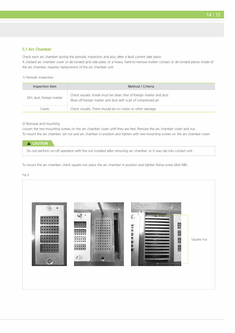
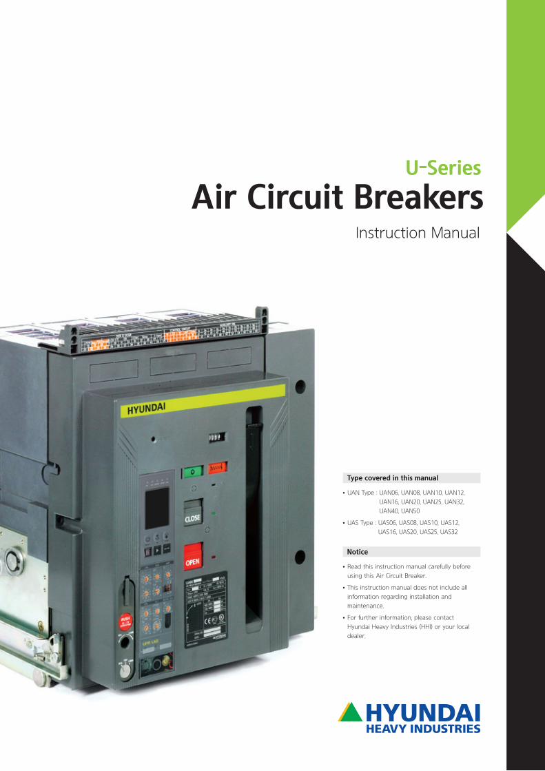
Fig. 6
Square nut
5.1 Arc Chamber
Check each arc chamber during the periodic inspection and also, after a fault current take place.
A cracked arc chamber cover or de-ionized grid side plate, or a heavy, hard-to-remove molten contact or de-ionized pieces inside of
the arc chamber, requires replacement of the arc chamber unit.
1) Periodic inspection
2) Removal and mounting
Loosen the two-mounting screws on the arc chamber cover until they are free. Remove the arc chamber cover and nut.
To mount the arc chamber, set nut and arc chamber in position and tighten with two-mounting screws on the arc chamber cover.
To mount the arc chamber, check square nut, place the arc chamber in position and tighten fixing screw (dish M6).
Do not perform on-off operation with the nut installed after removing arc chamber, or it may slip into contact unit.
CAUTION
14 | 15
Inspection Item Method / Criteria
Dirt, dust, foreign matterCheck visually. Inside must be clean, free of foreign matter and dust.
Blow off foreign matter and dust with a jet of compressed air.
Cracks Check visually. There should be no cracks or other damage.

| U-Series | Air Circuit Breakers Instruction Manual
1) Periodic inspection
(1) Arcing contact
Inspection Item Method / Criteria
Contact tip surface
- Check visually.
- Melting mark in the contact point tip surface is not a problem because it is a normal
phenomenon by close-open arc.
- Remove dirt, dust, grease, etc.
- When the arcing contact is melted less than 33 % original thickness, it should be replaced.
For replacements, please contact us.
(2) Main contact
If contact surface is badly worn or become rough, you should clean the surface in case of periodic inspection.
Fig. 7
1 Arc runner
2 Up terminal
3 In/out terminal body
4 Main fix contact tip
5 Arc fix contact tip
6 Arc move contact tip
7 Arc move contact
8 Main move contact
9 Main move contact tip
10 Low terminal3
5
4
3
2
17
8
9
10
6
05 Periodic Inspection and Parts Replacement
5.2 Contact Unit
Contact unit are visible and accessible when the arc chamber is removed.
Check the contact unit during a periodic inspection and after a short-circuit fault current take place.
When scrubbing contact trips' surface, pay attention to not let dust fall into the breaker mechanism.
After dressing, be sure to wipe and clean contact trips.
CAUTION
1) Periodic maintenance
Check the operating mechanism in detail as much as possible.
If there are parts that seem to be checked or hard to check, please contact us.
Inspection Item Method / Criteria
OperationOpen and close breaker through manual control to check the mechanical parts for normal
operation (every six months).
LubricationAdd a small amount of grease to each of the pins, shafts and their bearings (every six months).
Avoid excessive oiling to prevent the accumulation of dirt and dust.
Screws, bolts and springs
Check screws and bolts on each part for signs of loosening. Tighten them if loose.
Check each spring for proper engagement and damage.
Correct problem through repair or replacement (every six months).
Dirt and dust Latching parts should be free of dirt and dust. Wipe them with a clean cloth (every six months).
Fig. 8
1 Arc chamber
2 Move contact fix base
3 Crossbar unit
4 Open lever
5 Close lever
6 Charged/Discharged indicator
7 Open latch
8 Close latch
9 CO latch
10 Closing cam
11 Mechanism frame
12 Current transformer
12
11
1
6
7
8
9
10
5 4 3 2
5.3 Operating Mechanism
16 | 17

| U-Series | Air Circuit Breakers Instruction Manual
14
5
4 3 2 1
6
8
9
10
7
13
12
11
05 Periodic Inspection and Parts Replacement
5.4 Internal Accessories
Loosen the two front cover mounting screws and open the front cover (Fig. 1. ②) to check internal accessories.
Do not place your fingers or a tool in the gap between close/open and charged/discharged indicator (Fig. 9. ⑥, ⑫)
since this gap is closed when the breaker is closed.
Do not attempt to put hand or a tool into the breaker when closing springs are charged.
Be sure to discharge the closing springs prior to internal inspection.
Do not operate the on-off operation arbitrarity (qualified personnel only).
CAUTION
Fig. 9
1 Auxiliary switch
2 Shunt (SHT)
3 Cycle counter
4 LRC (latch release coil)
5 MHT (magnetic hold trigger)
6 Close/Open indicator
7 Close button
8 Over current relay (UPR)
9 Open button
10 Device of drawing in/out
11 Spring charging motor
12 Charged/Discharged indicator
13 Manual charging handle
14 Automatic connection
control jack

1 Shunt coil
2 Shunt terminal
3 Shunt/LRC mounting support fixing bolt
(R/H, M4)
4 LRC terminal
5 LRC coil
6 Shunt moving core-trip rod assembly check
7 Trip-rod
(2) Replacement of SHT (Fig. 10)
• Remove the two pin terminal from the control jack terminals (Fig. 10. ②).
• Remove the one support mount screws (Fig. 10. ③) and take out LRC-UVT-SHT support.
• Remove the coil mount screws (Fig. 13. ③).
• A new coil is properly assembled, and during attaching it. The trip-rod and shunt moving core position is shown as in Fig. 10. ⑥, ⑦.
• After checking the light movement of the moving core of new SHT, mount it in the breaker as it was.
• Connect the two pin terminal to the control jack terminals, and test the ACB and trip lever both electrically and mechanically for
normal operation (number 7, 8).
4 2
5 1
3
7
6
1) Shunt trip device (SHT)
Rated Voltage Coil Resistence
AC/DC110 40 Ω ± 5 %
220 68 Ω ± 5 %
AC380 120 Ω ± 5 %
440 120 Ω ± 5 %
DC24 12 Ω ± 5 %
48 22 Ω ± 5 %
(1) Periodic inspection (Fig. 21. reference)
Inspection Items Methods / Criteria / Dispositions
Operation
- Push the moving core of SHT with a pointed tool, such as a screwdriver trip, then, slowly release
the core. The result is acceptable if the core returns lightly.
- Push in the moving core slowly after closing the breaker. The result is acceptable if breaker trips open.
- The result is acceptable, if the breaker trips open at less than 70 % of the rated voltage after
closing the breaker.
Coil- Measure the coil resistance with an ohmmeter.
If it is much lower than the value shown in table or there is no continuity, replace the coil.
Terminals and mounting screws - Check terminals and mounting screws. Tighten them if loose.
Fig. 10. Shunt trip equipment mounting
18 | 19

| U-Series | Air Circuit Breakers Instruction Manual
2) Undervoltage trip device (UVT)
• UVT coil uses only DC rating.
• The under-voltage trip device includes instantaneous trip type and time delay trip type having 0.5 sec, 1 sec, 1.5 sec and 3 sec time
delay characteristics.
(1) General view of undervoltage trip coil & controller (time delay trip type)
(2) Periodic inspection
Inspection Items Methods / Criteria / Dispositions
Operation
- The breaker can not be closed when the UVT is de-energized. Because of this, if the breaker can be
closed at more than 85 % of the rated voltage, moving core becomes pick-up, the result is acceptable.
- If the breaker can be tripped from 35 % to 70 % of the rated voltage after closing the breaker,
the result is acceptable.
Coil resistance
- Measure the coil resistance with an ohmmeter. If the
measured resistance is much lower than the value shown
in the right or there is no continuity, replace the UVT coil.
Coil resistance (Ω)
118 Ω ± 5 %
Terminals and mounting screws - Check terminals and mounting screws for loosening. Retighten them if loose.
1 UVT coil
2 UVT controller
3 Wire terminal
4 UVT controller
mounting hole
(3) Replacement of UVT controller
When it is necessary to replace the UVT controller, replace the whole UVT controller unit.
• Remove the UVT wire at the wire terminal (Fig. 11. ①).
• Remove UVT mounting bolt (2-M6x10) (Fig. 11. ④).
• Take out the UVT controller.
• Install new UVT controller as it was on the breaker with UVT mounting bolt (Fig. 11. ④).
• Connect the wire terminals with fasten terminals at the same time.
• Test the UVT both electrically and mechanically.
1
2
4
3
05 Periodic Inspection and Parts Replacement
Fig. 11. UVT coil & UVT controller (only time delay type applied)
When inspecting the performance, rated voltage should be supplied unless ACB will not operate.
CAUTION
Recheck the wire terminal before suppling power.
Incorrect wiring may cause coil burning.
CAUTION

3) Latch release coil (LRC)
Coil resistance is same with SHT.
(1) General view of latch release coil (LRC)
(2) Periodic inspection
Inspection Items Methods / Criteria / Dispositions
Operation
- Push the moving core with a pointed tool, such as a screwdriver tip, then, slowly release the core.
The result is acceptable if the core returns lightly.
- Charge the closing springs and push the moving core.
The result is acceptable if the closing springs are discharged.
- If the breaker can be closed at 85 % of the rated voltage, the result is acceptable.
Coil resistance- Measure the coil resistance with an ohmmeter. If resistance was much lower than the value
shown in table.1 (page 19) or there is no continuity, replace the LRC.
Terminals and mounting screws - Check terminals and mounting screws for loosening. Tighten them if they are loose.
1 Terminal
2 Moving core
3 LRC mounting bolt tap (M5 tap. 1ea)
12
3
Fig. 12
(3) Replacement of LRC (unit replacement)
• Remove the pin terminal from the control jack terminals (Fig. 10. ④).
• Remove support mounting screw (Fig. 13. ②) M4, and take out the LRC-UVT-SHT support.
• Remove coil mounting screw (Fig. 13. ②).
• After checking the movement of the new LRC moving core, mount it in the breaker as it was.
• Connect the pin terminal to the control jack terminals (Fig. 10. ④).
• Test the device both electrically and mechanically for normal operation in the same manner described in periodic inspection table.
Take care when checking on/off operation by using mechanism manual button.
Fingers may be pinched during operation.
CAUTION
3
1
2
Fig. 13
1 Shunt/LRC mounting support
2 LRC mounting (R/H M5)
3 Shunt mounting (R/H M5)
20 | 21

| U-Series | Air Circuit Breakers Instruction Manual
(2) Periodic inspection
Inspection Items Methods / Criteria / Dispositions
Operation
- Take the breaker body out of the cradle.
- Connect the ohmmeter or alarm (buzzer) to each switch element.
- Check that a-contact is ON and b-contact is OFF when breaker is CLOSED, and that a-contact
is OFF and b-contact is ON when breaker is OPEN.
Contact surface - If contact is excessively worn or rough, replace whole switch unit.
Terminals and mounting screws - Check terminals and mounting screws. Tighten them if loose.
(3) Replacement of auxiliary switch unit (Fig. 17)
The auxiliary switch unit is an assembly of 10 circuits (5 a-contacts and 5 b-contacts).
Replace the whole switch unit even if there is a partial defect.
• Remove the auxiliary switch assembly bolt (1-M6 wrench bolt) (Fig. 14. ①).
• Change wire circuit.
• Tighten the auxiliary switch assembly bolt (1-M6 wrench bolt).
• Conduct periodic inspection mentioned in (2) above and make sure if the switch operates normally.
41
43
45
47
49
5153
5557
59
42
44
46
48
5052
5456
5860
1
05 Periodic Inspection and Parts Replacement
4) Auxiliary switch unit
(1) General view of auxiliary switch unit, connection circuit
Fig. 14. Aux, switch general view Fig. 15. Aux. switch connection circuit
Replaced terminal must be properly connected before operating.
CAUTION
5) Motor unit
(1) Motor unit general view
Fig. 16
1 Motor rotor
2 Motor mounting hole
3 Motor control unit
3
2
1
1
2
(2) Operation check
Open and close the breaker through electrical control to check the relay for normal operation.
Do this in the following procedure.
• After checking front-cover, with the push-button switch ON, close the breaker.
• Normal operation is when the breaker is closed, the motor is rotating and the charged/discharged indicator displays「 」.
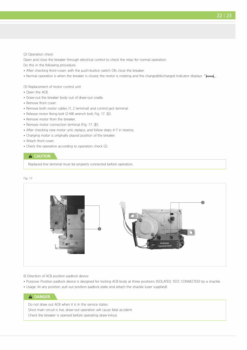
(3) Replacement of motor control unit
• Open the ACB.
• Draw-out the breaker body out of draw-out cradle.
• Remove front cover.
• Remove both motor cables (1, 2 terminal) and control jack terminal.
• Release motor fixing bolt (2-M6 wrench bolt, Fig. 17. ①).
• Remove motor from the breaker.
• Remove motor connection terminal (Fig. 17. ②).
• After checking new motor unit, replace, and follow steps 4-7 in reverse.
• Charging motor is originally placed position of the breaker.
• Attach front cover.
• Check the operation according to operation check (2).
Replaced line terminal must be properly connected before operation.
CAUTION
Fig. 17
6) Direction of ACB position padlock device
• Purpose: Position padlock device is designed for locking ACB body at three positions (ISOLATED, TEST, CONNECTED) by a shackle.
• Usage: At any position, pull out position padlock plate and attach the shackle (user supplied).
Do not draw out ACB when it is in the service states.
Since main circuit is live, draw-out operation will cause fatal accident.
Check the breaker is opened before operating draw-in/out.
DANGER
22 | 23
| U-Series | Air Circuit Breakers Instruction Manual
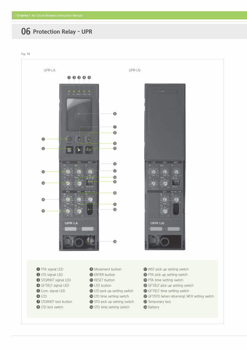
17 INST pick up setting switch
18 PTA pick up setting switch
19 PTA time setting switch
20 GFT/ELT pick up setting switch
21 GFT/ELT time setting switch
22 GFT/STD (when returning), MCR setting switch
23 Temporary test
24 Battery
9 Movement button
10 ENTER button
11 RESET button
12 LIST button
13 LTD pick up setting switch
14 LTD time setting switch
15 STD pick up setting switch
16 STD time setting switch
1 PTA signal LED
2 LTD signal LED
3 STD/INST signal LED
4 GFT/ELT signal LED
5 Com. signal LED
6 LCD
7 STD/INST test button
8 LTD test switch
UPR-LA UPR-LN
6
7
8
9
10
15
16
17
22
20
21
2319
18
14
13
12
11
1 2 3 4 5
24
06 Protection Relay - UPR
Fig. 18

Type UPR-LA, LAG, LAZ, LP, LH, SA, SP OCR is LCD display type.
Protective FunctionUPR Multifunction Protective Device
For General Feeder Circuits
For General Protection
UPR-LN -
UPR-LA -
UPR-LAG -
UPR-LAZ -
UPR-LP -
UPR-LH -
- UPR-SN
- UPR-SA
- UPR-SP
AL AS
AL AS
AL AS
AL AS
AL AS
AL AS
AL AS
AL AS
AL AS
AI
AI
AI
AI
AI
AI
AI
AI
AI
AP
AP
AP
AP
AP
AP
AP
MCR
MCR
MCR
MCR
MCR
MCR
MCR
AG
AG
AG
AG
AG
AG
ELT
ELT
IU
IU
CP/I
CP/I
CP/I
CP/I
CP/I
CP/I
CP/I
Needed
UPR is a CPU loaded, high-reliability, multifunctional protection relay for U-Series ACB.
This protection relay is classified into types UPR-1L, 2L (for general feed circuits) and type UPR-1S, 2S (for generator protection).
Refer to the following protective function combination table.
Protective function combination table
Control Power Supply
Indication Contact
Needed
Needed
Needed
Needed
Needed
Needed
24 | 25
AS
AI
AG
MCR*
Instantaneous trip
Ground fault trip
Function is an option
Making current release (option)
IU
CP/I
AL
AP
ELT
Contact for operation indication
Tripped LED indicator and contact
Long time delay trip
Pre-trip alarm
Short time delay trip * The function check is provided in UPR protection relay
with CP-I, allowing a simple field test.

| U-Series | Air Circuit Breakers Instruction Manual
6.1 Rated Current
Type Rated Current [In]
UPR-L type
- Rated current [In] can be adjusted to 50 %, 63 %, 70 %, 80 %, 90 %, and 100 % of the
rated primary CT current [ICT].
- On the UPR nameplate, rated current [In] is marked.
- Rated current [In] can be selected by sliding the base current setting select switch,
which can be set to the predetermined scale.
UPR-S type
- A proper CT is selected according to the rated current [IGEN] of generator.
Rated current [In] is adjusted to be equal to the rated current value [IGEN] of generator by the
rotary switch inside UPR-S.
Accordingly, the rated current value [IGEN] of generator corresponds to rated current [In].
On the UPR nameplate, rated current [In] is marked.
6.2 Protective Functions and Setting Ranges
Protective Function Current Setting Range Time Setting Range
LTD
trip
(Ir,Tr)
Type
UPR-L
- The scale is marked as magnification
of [In].
- Current setting range is 10 steps
(Non, 0.8, 0.83, 0.85, 0.88, 0.9, 0.93,
0.95, 0.98, 1.0) times of [In].
- When [Ir] is set to NON the protective
function, it does not operate.
- The breaker is not tripped at less
than 105 %, and tripped at more
than 120 % of [Ir] setting.
- The setting dial is scaled in a few
seconds, which is the operating time
at 600 % of [Ir] setting.
- Time setting range is 10 steps of 0.5,
1.25, 2, 2.5, 5, 10, 15, 20, 25, and 30
seconds.
- The breaker is tripped at the range
from -15 % to +15 % of time setting
range.
Type
UPR-S
- The scale is marked as magnification
of [In].
- Current setting range is eight steps
(NON, 0.7, 0.8, 0.9, 1.0, 1.05, 1.1, 1.15,
1.2, 1.25) of [In].
- When [Ir] is set to NON the protective
function, it does not operate.
- The setting dial is scaled in a few
seconds, which is the operating time
of current flow at 120 % of [Ir]
setting.
- Time setting range is nine steps of
10, 15, 20, 25, 30, 35, 40, 50, and 60
seconds (error extent is 5 %).
INST
trip
(Ii)
Type
UPR-L
- The scale is marked as magnification
of [In].
- Current setting range is nine steps
(NON, 2, 3, 4, 6, 8, 10, 12, 15) of [In].
- When [Ii] is set to NON the protective
function, it does not operate.
- Time setting is unnecessary.
Type
UPR-S
- The scale is marked as magnification
of [In].
- Current setting range is nine steps
(NON, 2, 3, 4, 6, 8, 10, 12, 15) of [In].
- When [Ii] is set to NON the protective
function, it does not operate.
06 Protection Relay - UPR

Protective Function Current Setting Range Time Setting Range
STD trip
(Isd, Tsd)
Type
UPR-L
- The scale is marked as magnification
of [In].
- Setting dial is scaled in multiples of
[In].
- There are ten discrete setting
positions: NON, 1, 1.5, 2, 2.5, 3, 4, 6, 8,
10 times [In].
- When [Isd] and [Ii] are set at NON, the
device is operated at 1,000 % of [In]
setting as a fail-safe function by [Tsd]
setting.
- Setting dial is scaled in milliseconds,
which is the operating time at
current flow higher than [Isd] 120 %
setting.
- There are six discrete 50, 100, 200,
300, 400, 500 milliseconds.
Type
UPR-S
- The scale is marked as magnification
of [In].
- Setting dial is scaled in multiples of [In].
- There are nine discrete setting
positions: NON, 1, 1.5, 2, 2.5, 3, 3.5, 4,
4.5, 5 times [Io].
- When [Isd] and [Ii] are set at NON, the
device is operated at 500 % of [In]
setting as a fail-safe function.
- Setting dial is scaled in milliseconds,
which is the operating time at
current flow higher than [Isd] 120 %
setting.
- There are six discrete setting
positions: 50, 100, 200, 300, 400, 500
milliseconds.
GFT
(Ig)
Type
UPR-L
- The scale is marked as magnification
of UPR rated primary current [ICT].
- The current setting range is 10
steps (NON, 0.1, 0.2, 0.3, 0.4, 0.5, 0.6,
0.7, 0.8, 1.0 times of [ICT]).
- Setting dial is marked as relay
operation time. The mark is
milliseconds.
- The current setting range is six steps
(50, 100, 200, 300, 400, 500
milliseconds).
ELT
(IΔt)
Type
UPR-L
- The scale is marked as magnification
of UPR rated primary current [ZCT].
- The current setting range is six
steps (NON, 0.5, 0.8, 1, 2, 3, 5 A of
[ZCT]).
- If setting primary current is applying
an electric current, two modes of
alarm and trip are established.
- Alarm setting range is five steps (140,
230, 350, 800, 950 milliseconds).
- Trip setting range is five steps (60,
140, 230, 350, 800 milliseconds).
Pre-alarm
(IP)
Type
UPR-L
- The scale is marked as magnification
of UPR rated primary current [In].
- The current setting range is 10
steps methods (NON, 0.6, 0.65, 0.7,
0.75, 0.8, 0.85, 0.9, 0.95, 1.0 times of
[In]).
- Setting dial is marked as relay
operating time. The mark is seconds.
- The current setting range is 10
steps (5, 10, 15, 20, 40, 60, 80, 120,
160, 200 seconds).
Type
UPR-S
- The scale is marked as magnification
of UPR rated primary current [In].
- The current setting range is 10
steps methods (NON, 0.7, 0.75, 0.8,
0.85, 0.9, 0.95, 1.0, 1.05, 1.1 times of
[In]).
- At 120 % of [Ip], nine steps are
available (1, 5, 10, 15, 20, 25, 30, 35,
40 seconds).
26 | 27

| U-Series | Air Circuit Breakers Instruction Manual
• After adjustment, check a set point by using a test function and tester of UPR checker (optional item).
• Return the transparent UPR cover (Fig. 19. ①) to its original position.
Rotary step switches
Rotate the dial until the arrow points to the desired position.
The setting is the same within the scale range denoted by a bold line.
Slide switches
Slide the switch knob up/down to turn on/off.
ON ON MCRIg2t Isd2t
OFF OFF INST
1
2
06 Protection Relay - UPR
1) Method of changing protective function settings
The settings of type UPR protection relay can be changed easily by dial operation.
This section describes the basic procedures for setting the protective device.
For setting details of individual protective functions see page 26-27.
(1) Basic procedures
• To release the UPR safety cover attached to the front of the ACB, insert a flat-head screwdriver at ①.
• Adjust setting switches with a small flat-head screwdriver.
UPR is composed of two setting switch.
Do not apply excessive force to the switches.
The switches should be turned lightly or slid with the screwdriver.
CAUTION
Fig. 19

• Isd2t ON/OFF
STD time characteristic is divided into definite time and inverse time, it can be selected.
• INST/MCR
Instantaneous characteristic can be selected INST or MCR.
When MCR is selected, must be sure to observe, following condition:
Estimated short-circuit current ≦ Rated breaking current (without INST).
※ MCR is a protective function which instantaneously trips open the breaker only when a
fault current exceeding STD current setting value is applied at making operation
of the breaker. After making operation, MCR function is not working.
6.3 Operation Indication Functions
The operation indication function includes IU contact for tripped indication (whole indication).
1) IU contact for tripped indication (whole indication) (UPR-L, UPR-S)
• This contact output is one contact operating even when of LTD, STD, INST, or GFT operates.
• The contact output (Fig. 1. ⑬) is transmitted between the terminals ㉒ and ㉓ of disconnecting device for control circuit.
• Rating of contact for tripped indication.
Rated Voltage AC 250 V DC 30 V DC 125 V DC 250 V
Rated current (resistive load) 8 A 5 A 0.5 A 0.3 A
Rated current (inductive load) 3 A 3 A 0.25 A 0.15 A
Ig2t ON/OFF
Isd2t ON/OFF
MCR ON/OFF
Ig2t OFF: For definite time characteristic
Ig2t ON : For inverse time characteristic, which has Ig2t=C (constant) characteristic
at 100 % of a set point, please refer to product catalogue for detail.
Tolerance of setting current is ±30 %.
Isd2t OFF: For definite time characteristic
Isd2t ON : For inverse time characteristic, which has Isd2t=C (constant) characteristic
at 100 % of a set point, (500 % for marine application) please refer to
catalogue for detail. Tolerance of setting current is ±20 %.
ON ON ONMCRIg2t Isd2t
OFF OFF OFF
ON ON ONMCRIg2t Isd2t
OFF OFF OFF
(2) The setting of slide switch
• Ig2t ON/OFF
GFT time characteristic is divided into definite time and inverse time, it can be selected.
ON ON ONMCRIg2t Isd2t
OFF OFF OFF
28 | 29
| U-Series | Air Circuit Breakers Instruction Manual
Operation signal contact terminal (UPR-2L-GS)
㉒-㉑ : LTD contact terminal ㉒-㉔ : STD/INST contact terminal
㉒-㉓ : PTA contact terminal ㉒-㉕ : GFR/ELT contact terminal
06 Protection Relay - UPR
2) CP/I LED light and contact for tripped indication (type UPR-LA, LAG, LAZ, LP, LH, SA, SP)
• Control power is required for tripped indication. Supply the following power between terminals ⑲ and ⑳ of control circuit
disconnecting device (Fig. 1. ⑫).
- AC 100-125 V / 10 VA or AC 200-250 V / 10 VA
- DC 100-125 V / 10 W or DC 200-250 V / 10 W or DC 240 V / 10 W
• When LTD, STD or GFT operates, the LED lights for tripped indication (Fig. 18. ②, ③, ④) light up individually.
• At the same time, the contact signal ON is outputted individually between terminals ㉒-㉑ of control circuit disconnecting device (Fig. 1. ①).
• The LTD, STD and GFT tripped indications remain ON until the reset button (Fig. 18. ⑩) is depressed.
Pressing the reset button for more than one second resets the ON state.
• LED light and contacts for Pre-trip alarm operation indication
- The PTA pickup indication LED light (Fig. 18. ①) flickers at more than pickup current value [IP].
At the same time, the contact signal ON is outputted between terminals ㉒-㉓ of control circuit.
- The operation indication is automatically reset if the current of less than [IP] is reached.
※ Push the reset button (Fig. 18. ⑩).
If the abnormality is temporary, such as noise, the LED will turn off. At that time, the control function returns to normal.
If the LED does not go off after pushing the reset button, some abnormality may occur.
In this case, immediately contact to HHI.
• Rating of contact for tripped indication
Rated Voltage AC 250 V DC 220 V
Rated current (resistive load) 125 VA (MAX 2 A) 60 W (MAX 2 A)
Rated current (inductive load) 20 VA (MAX 2 A) 10 W (MAX 2 A)
6.4 Field Test
1) Function check method
• A simple check of operation for type UPR protection relay can be made with a test switch.
• Function check of the ground fault trip function is not possible (for ground fault trip function, portable UPR checker can be possible).
2) Necessity for function check
• Stop watch.
• A flat-head screwdriver
• Control power supply: Use marking plate of type UPR multifunction protective device if test in the test position checks function, check
whether control power supply ⑲ to ⑳ of control circuit short device (Fig. 1. ⑫).
For function check of each protective function, draw out the breaker to the ISOLATED position, or take it out from the draw-out cradle.
If making function check in the TEST position, confirm that there is no influence on the sequence.
CAUTION

3) Protective function check
Protective Function Type UPR-L (for general feeder circuit) / Type UPR-S (for generator protection)
LTD
1. Close the breaker.
2. In case of UPR-L, when short time delay and instantaneous time setting current value is lower than
rated current, each dial should be in "NON" position using a flat-head screwdriver .
3. Push the "LOW" test switch (Fig. 18. ⑪) (current flow of 6 times the rated current [In] in type UPR-L,
and 1.2 times the rated current in type UPR-S), and at the same time, measure the tripping time with a
stopwatch.
Also, hold the test switch until the breaker is tripped.
4. After tripping, release the test SW. Push the RESET button to OFF (neutral) automatically.
5. Read the tripped time. in case of type UPR-L, by flowing current (6 times of [In], 1.2 times of [In]), If it is
nearly equal to the operation time, at the current of 6 times [In] for UPR-L and 1.2 times [In] for UPR-S,
it is normal.
6. After the LCD test, short time delay and instantaneous time setting should be reset to original setting
value by flat head screwdriver.
In case of pre-trip alarm device, until the breaker is tripped, an alarm signal occur.
STD
1. Close the breaker.
2. Instantaneous time trip setting current dial should set to NON position using a flat-head screw-driver.
3. Push the test switch (Fig. 18. ⑫) to [HI] current flow of more than 15 times the rated current [In].
If the breaker is tripped with time delay setting, it is normal.
4. After tripping, release the test switch. Push the RESET button to OFF (neutral) automatically.
Return the STD pickup current setting dial to the original set value with a flat-head screwdriver.
INST
1. Close the breaker.
2. Push the test switch (Fig. 18. ⑫) to [HI] current flow of more than 15 times the base current [In].
If the breaker is tripped momentarily, it is normal.
3. After tripping, release the test switch. Push the RESET button to OFF (neutral) automatically.
30 | 31

| U-Series | Air Circuit Breakers Instruction Manual
6.5 Characteristic Check
Protective Function Type UPR-L (for general feeder circuit) / Type UPR-S (for generator protection)
LTD
Pick-up
current
1. Close the breaker.
2. Increase test voltage gradually from zero, pre-alarm trip, indicator LED (Fig. 18. ①), will flicker near the
long time setting current value.
3. Increase test voltage gradually until the long-time trip pick-up signal LED (Fig. 18. ②) turns on.
At this moment, the test voltage of type UPR-1L should be within 1.05-1.2 times of secondary voltage
converted from [Ir] current. In case of type UPR-1S, the test voltage should be within ±20 % of
secondary voltage.
4. Reduce the test voltage to zero.
※ LCD display is not available for type UPR-L and UPR-S.
Trip time
1. Close the breaker.
2. In case of type UPR-L, when short time and instantaneous time setting current value are lower than
6 times of rated current, each dial using a flat-bladed screwdriver should set NON position.
3. Type UPR-L and type UPR-S flow 6 times and 1.2 times current of setting value separately.
And at the same time, measure trip deadline as stopwatch or portable UPR checker.
4. The breaker is tripped in a range of ±15 %, it is normal.
5. Reduce the test voltage to zero.
6. In case of operation of [2], short time delay and instantaneous time setting dial should be reset original
setting value with a flat-head screwdriver.
LED display
LCD display
06 Protection Relay - UPR

Protective Function Type UPR-L (for general feeder circuit) / Type UPR-S (for generator protection)
Short time
delay trip
characteristic
check
Trip
setting
current
1. Close the breaker.
2. Set long time and instantaneous time trip setting current dial to non using a flat-head screw-driver.
3. Supply test voltage within ±15 % of secondary voltage converted from [Isd] setting current for type
UPR-L.
If the breaker trips, it is normal. In case of type UPR-S, test voltage is within ±10 % of secondary
voltage.
4. Reduce the test voltage to zero.
Trip time
1. Close the breaker.
2. Set the test equipment output to 1.2 times the secondary current levels converted from the set value
[Isd] current.
3. Apply test voltage. At the same time, start the trip delay measurement with a stopwatch.
4. If the breaker is tripped, reduce the test voltage to zero.
5. Read the trip time. If the trip time is within the range of resettable time (ms) and maximum total
clearing time (ms) shown in the table below, it is normal.
Time setting [Tsd] (ms)
Six step system 50 100 200 300 400 500
Resettable time (ms) 35 60 150 240 330 400
Max. total clearing time (ms) 120 170 270 380 480 580
6. Return the LTD/INST pickup current setting dial to the original set value with a flat-head screwdriver.
INST
Trip
setting
current
1. Close the breaker.
2. If the breaker doesn't trip at the test voltage of -20 % of secondary voltage converted from [Ii] setting
current and trips at +20 % of secondary voltage, it is normal.
32 | 33

| U-Series | Air Circuit Breakers Instruction Manual
06 Protection Relay - UPR
Protective Function Type UPR-L (for general feeder circuit) / Type UPR-S (for generator protection)
Pre trip
alarm
Pick-up
current
1. Close the breaker.
2. Increase the test voltage up to the position in which the pre-alarm indicator LED (Fig. 18. ①) flickers.
If the current value at that time is within the range of 7.5 % (UPR-L) and 5 % (UPR-S) of secondary
voltage levels converted from the set value [IP] current, it is normal.
3. Reduce the test voltage to zero.
Trip time
1. Supply the specified control power.
2. Apply the test voltage of 1.1 times (UPR-L) and 1.2 times of (UPR-S) of secondary voltage levels
converted from the set value [IP] current.
At the same time, start the time measurement with a stopwatch.
- If the time at which an alarm signals is outputed across COM-PTA terminals is within the range of 20 %
(UPR-L) and 15 % (UPR-S) of the set value [TP] second, it is normal.
- Reduce of the test voltage to zero.
GFT
Trip
setting
current
1. Close the breaker.
2. Apply the test voltage within the range of 20 % of secondary voltage levels converted from the set
value [IG] current: If the breaker is tripped, it is normal.
3. Reduce the test voltage to zero.
Trip time
1. Close the breaker.
2. Set the test equipment output to 120 % of the secondary voltage levels converted from the set value [ICT] current.
3. Apply the test voltage. At the same time, start the trip delay measurement with a stopwatch.
4. If the breaker is tripped, reduce the test equipment output to zero.
5. Read the trip time. If the trip time value is within the range of resettable time (ms) and maximum total
clearing time (ms) shown in the table below, it is normal.
Time setting [T ] (ms)
Six step system 50 100 200 300 400 500
Resettable time (ms) 35 60 150 240 330 400
Max. total clearing time (ms) 120 170 270 380 480 580
Neutral
protection
NON
1. Set when switchboard system does not needs neutral pole protection.
2. It is only possible with control power supply type of OCR.
3. It is impossible with UPR-LN, SN type of OCR.
50n
(@0.5 In)
1. It operates at 50 % of In value.
2. LTD current of neutral pole is same as 50 % of Ir setting value.
3. STD current of neutral pole is same as 50 % of Isd setting value.
4. INST operates at 100 % of Ii setting value.
5. It is impossible with UPR-LN, SN type of OCR.
100n
(@ In)
1. It operates at 100 % of In value.
2. LTD current of neutral pole is same as 100 % of Ir setting value.
3. STD current of neutral pole is same as 100 % of Isd setting value.
4. INST operates at 100 % of Ii setting value.
5. For UPR-LN, SN type of OCR. It is basically set as 100 %
g

6.6 Operating Manual for UPR-LA, LAG, LAZ, LP, LH, SA, SP Type
1) Simplicity test methods
2) The beginning screen
For LTD simplicity test, control
source of UPR (AC/DC 110-220 V)
is approved.
If you push continually low button,
with PTA/LTD LED flickering, it starts
perception
After time delay, LTD LED turning
on, at the same time, LTD ground
point is printed. ACB is open.
In order to remove printed ground
point, after pushing reset button, all
output LED is turned on and off. Also,
the print contact point is removed.
For STD/INST simplicity test,
control source of UPR
(AC/DC 110-220 V) is approved.
In case of STD/INST, if you push
hi button, INST LED and ground
point is printed. In case of INST/
NON, STD ground point is printed.
STD/INST accident signal and
ground point is printed.
ACB is open.
In order to remove printed ground
point, after pushing reset button, all
output LED is turned on and off. Also,
the print contact point is removed.
STD/INST test
LTD test
The beginning screen
If control source is applied, each phase load-current is automatically displayed in regular sequence of R-S-T-N.
Under the rated 2 %, it marks "0".
In case of pickup setting switch change
In case of pick up setting switch adjustment, setting value is automatically
displayed and after turning on back light, it is automatically turned off.
In case of time setting switch change
In case of setting switch adjustment, setting value is automatically displayed and after turning on
back light, it is automatically turned off.
34 | 35

| U-Series | Air Circuit Breakers Instruction Manual
It explains relay menu and key operation method, setting method
through window and example.
By using key panel below, it can use all menu of the relay.
There is a button saving list for checking setting data.
There is a button for moving data.
After moving to the item you want to know, there is a button
for carrying out.
3) Data check method
• List button ( ) - In case of pushing 1 time: Shows maximum current.
×1 time
×2 times
• List button ( ) - In case of pushing 2 times: Voltage confirmation (E type only)
For E type, pushing list button twice shows measured voltage value.
When it is 3P type, it shows phase-to-phase voltage only. And when it is 4P type, it shows both phase-to-phase
voltage and phase voltage. By pushing movement button you can check voltage value which you want.
This mode shows phase with maximum current.
Push list button once.
Push list button twice. Using movement button, you can confirm voltage.
For E type, pushing list buttom 3 times shows measured power value. Each value shows each total for P, Q, S, PF
in sequence. In case of negative PF value, positive value will be shown marked with R (reverse).
• List button ( ) - In case of pushing 3 times: Power confirmation (E type only)
06 Protection Relay - UPR
×3 times

• List button ( ) - In case of pushing 4 times: Energy
• List button ( ) - In case of pushing 5 times: Fault confirmation
This mode shows active energy value.
Energy is shown in two screens. When there is remaining value, arrow will shown and you can move by movement button.
This is list checking accident record. The accident is stored in 10 data at this point in time, F001 is the newest.
In case of data number exceeds, it is automatically deleted from the older data. Accidental contents, type-phase
load current and accident occurrence time are stored, and you can confirm it by movement button.
Time information is shown in year, month, day, hour, minute in sequence. After choose data with movement
button and then push enter button, you can check saved data.
This mode can check pickup setting value and time setting value per each item.
You can check each menu by movement button in regular sequence of LTD > STD > INST > PTA > GFT > ELT.
Each menu shows its pickup setting value, delayed time value moving by button.
• List button ( ) - In case of pushing 6 times: Set information confirmation.
×4 times
×5 times
×6 times
36 | 37
| U-Series | Air Circuit Breakers Instruction Manual
• List button ( ) - In case of pushing 7 times: Frequency confirmation
• List button ( ) + Movement button ( ) - In case of pushing both for 3 seconds : Neutral protection setting
• Movement button ( ) - In case of pushing it twice: Setting in (SA type only)
You can set the frequency value. Frequency is available for 50/60 Hz.
※ When changing frequency, you have to reboot it with power source once disconnected and reconnect it.
This is N phase protection. N phase protection can be set as 100 %, 50 %, non of In value.
Once you push enter button, figures flash, it turns into setting mode. Use hi/low button during this setting mode
and then press enter button when you finished setting.
Flashing
Flashing
FlashingThis is only for the SA type of OCR.
For the marine type you can set the in value. Pressing the enter button,
figures flash, it turns into setting mode. Using hi/low button to adjust
value, and press the enter button when you finished setting.
Setting value is available for 50-100 % of Ict, with 1 A unit.
This is communicational parameters setting mode. Pressing enter button at each screen make figures flashing,
turning into setting mode. Using hi/low button to adjust value, and press the enter button when you finished setting.
• Communication protocol : Modbus-RTU • Data bit: 8 bit • Parity: non • Stop bit: 1
Modbus address can be set between 1-240, and basically set as 1.
Baud rate can be set as 9,600/19,200/38,400 and basically set as 38,400.
Swap is transmitting function which able to transmit data byte more than word.
Ex) 0×1234 > 0×3412
Modbus address
1-240
Baud rate
9,600/19,200/38,400
38,400 (default)
Swap
ON, OFF (default)
• Movement button ( ) - In case of pushing it 1 time: Baud rate setting
06 Protection Relay - UPR
×7 times

• Movement button ( ) - In case of pushing it twice : Demand time setting (P type only)
• Movement button ( ) - In case of pushing it 3 times: Network setting.
• Movement button ( ) - In case of pushing it 4 times: Power factor sign convention setting (P type only)
Demanding value is average value during given time.
Set the time for demanding value calculation of power and current.
Pressing enter button, figures are flashing, it turns into setting mode.
Using hi/low button to adjust value, and press the enter button when you
finished setting.
Time setting is available from 5 to 60 minutes, by 1minute unit.
Default setting is 15 minutes.
This is setting mode of network type.
It is restricted by type of OCR 3-pole/4-pole.
※ Network setting criteria is determined by type of ACB.
ACB CT OCR type Network
3 3-poles 3P3W, 3P4W
4 4-poles 4P4W
※ In case of 3P ACB but with 4 wire connection, you have to
set network as 3P4W.
When you press enter button, figures are flashing, it turns
into setting mode. Using hi/low button to adjust value, and
press the enter button when you finished setting.
This is setting mode regarding power factor sign convention according to IEC and IEEE.
Signs are determined from the active power and reactive power flow.
Pressing enter button, figures are flashing, it turns into setting mode. Using hi/low button to adjust value,
and press the enter button when you finished setting. Basic setting is IEC convention.
Flashing
Demand value
of active power
Demand value
of phase
Flow of active and reactive power
P from loadQ to load
P to loadQ to load
P from loadQ from load
P to loadQ from load
Q
P
38 | 39
IEEE
P = -Q = +PF= + (leading)
P = +Q = +PF= + (leading)
P = -Q = -PF= - (leading)
P = +Q = -PF= + (leading)
Q
P
IEC
P = -Q = +Pf = -
P = +Q = +PF= +
P = -Q = -PF= -
P = +Q = -PF= +
Q
P

| U-Series | Air Circuit Breakers Instruction Manual
4) Flow-current test of the main circuit
(1) Temperature test
If rated current flowed current to a 3-poles series connection and 1-phase source, the breaker functioning GFT will work and
trip the ACB.
This is 2-poles among 3-poles in the same direction, pick-up circuit inside UPR protection relay flows unbalanced current as a vector.
Therefore, in the temperature test in 1-pole source system, before test, separate NHT connection cable to prevent from GFT trip.
(2) Overcurrent trip test
Turn the GFT function knob to NON and execute LTD test.
To test relay setting with single phase source, ACB with GFT function will trip by GFT because of load unbalance.
- GFT function in a circuit breaker is in the single-phase type.
In the breaker functioning GFT, in case that the current in the 1-phase is approved by approving load unbalance GTF operates.
• Movement button ( ) - In case of pushing it 8 times: OCR version confirmation
• Movement button ( ) - In case of pushing it 9 times: OCR model number confirmation
This mode shows and sets the time of your OCR.
Time is expressed in year, month, day, hour, minute in sequence each in two digit number.
Pressing enter button, figures are flashing, turning into setting mode.
Using hi/low button to adjust value, and press the enter button when you finished setting.
※ OCR time runs by replaceable battery. You have to replace it when 'LOW'.
• Movement button ( ) - In case of pushing it 5, 6, 7 times: Time setting
This mode shows model number of your OCR.
This mode shows version of your OCR.
06 Protection Relay - UPR

The insulation resistance test and dielectric withstand test for main circuit and control circuit are performed as follows:
7.1 Main Circuit
• Dielectric withstand voltage performance is AC 3,500 V for one minute.
• Use a DC 500 V insulation resistance tester (megger) (over 300 ohm).
7.2 Control Circuit (to earth)
• Dielectric withstand voltage performance is AC 1,500 V for one minute.
For DC 24 V rating of motor charging and closing operation circuits, its characteristic is AC 500 V for one minute (control circuit
terminals ①, ②, ③).
For DC rating of the following control circuits, withstand voltage test is impossible.
- Control circuit terminals ⑨ and ⑩ of undervoltage trip device (UVT).
- The terminals ⑲ and ⑳ of UPR protection relay.
• Use DC 500 V insulation resistance tester (megger) for insulation resistance test.
07 Insulation Resistance Test and Dielectric Withstand Test
40 | 41

| U-Series | Air Circuit Breakers Instruction Manual
No. TroublePhenomenon
Expected Causes Corrective ActionsMachine Electrical
1Close
fault
× ×
1. Mechanism badness 1. Contact HHI
2. Whether it is charging by handle mechanism 2. Contact HHI
3. Is close rod returned ? 3. Close rod returning check
4. Whether inertia latch is jamming or not ? 4. Inertia latch movement check.
5. Is ACB placed in proper position
(ISO-TEST-CON) ?5. Move to proper position
6. Is UPR manual reset button pull out ? 6. Push back UPR manual reset button
7. Is UVT coil applied proper voltage ? 7. UVT source check
8. Is position lock button handle cover
pushed in ?
8. Handle cover comeback .
Push draw in/out handle and adjust position
confirm button returning
9. The breaker caught interlock ? 9. Interlock dissolution
10. Is trip latch turned down ? 10. Trip latch returning
× O
1. Is close rod returned ? 1. Close rod returning
2. Is trip latch turned down ? 2. Trip latch returning
O ×
1. Is proper voltage applied to CC coil ? 1. CC coil voltage check
2. Is CC coil operates normally ? 2. Coil replacement
3. Is CC coil stroke in proper position ? 3. Stroke check
4. Is UVT coil applied proper voltage ? 4. UVT source check
5. Is over current relay reset ? 5. Reset OCR
2Open
fault
× ×1. Whether any interlock system exist ? 1. Contact HHI
2. Whether trip latch exists bur ? 2. Contact HHI
O ×
1. Whether proper voltage applied to TC coil ? 1. TC coil voltage check
2. Whether TC coil exists mechanical interference 2. After voltage is applied, check core movement
3. Whether proper voltage applied to UVT coil ? 3. UVT coil voltage check
3Charging
fault
× ×1. Whether handle mechanism cam operates
normally ?1. Contact HHI
O ×
1. Whether proper voltage applied to motor ? 1. Voltage check (85-110 % of rated voltage)
2. Whether motor control unit is damaged 2. Motor output voltage check
3. Whether motor ratchet (M/B) is proper 3. Part check
08 Troubleshooting Points

k
kk
k
30 29
gn
KC
KB
KA
UPR
UPR-LN
UPR-LA
UPR-LAG
UPR-LAZ
UPR-LP
UPR-LH
N-line Source (or load)
09 Appendix
9.1 Neutral CT and UPR Protection Relay Connection Methods
In case of using 3-poles ACB with 3-phase 4-lines, both switchboard neutral pole and neutral pole CT are attached.
1) Neutral CT rating and specification
Frame ACB CT Rating (V)
A
UAN06/UAS06
UAN08/UAS08
UAN10/UAS10
UAN12/UAS12
UAN16/UAS16
UAN20
320/0.2
640/0.2
800/0.2
1,000/0.2
1,250/0.2
1,600/0.2
2,000/0.2
B
UAN20/UAS20
UAN25/UAS25
UAN32/UAS32
UAN40
2,000/0.2
2,500/0.2
3,200/0.2
4,000/0.2
C
UAN32
UAN40
UAN50
3,200/0.2
4,000/0.2
5,000/0.2
DUAN40
UAN50
4,000/0.2
5,000/0.2
2) Connection
Connect CT (the dotted line is tied up the user side) with attention of polarity.
※ The neutral pole CT class: Class 1.0
Connection diagram for natural CT of 3-poles ACB
When the CT polarity is connected reversely, ground fault protection function may cause a malfunction.
(ACB is set with K polarity, please assemble NCT as K polarity)
CAUTION
42 | 43

| U-Series | Air Circuit Breakers Instruction Manual
09 Appendix
9.2 Ground Protection Method
1) Grounded neutral Y-Y transformer
(1) In case of 3-poles ACB with 3-phase 4-lines
The neutral pole CT connects neutral pole terminals.
When remaining current of CT exceeds setting value, ACB is tripped to GFT.
As the ratio of the neutral poles lowers, apply HHI NCT (only for UPR optional).
Ig ICT×(0.1-0.2-0.3-0.4-0.5-0.6-0.7-0.8-1.0- Non) 10 steps
Pickup Current Adjustment ICT×from 0.1 to 1.0 type-step temporarily adjustment
Tolerance ±20 %
Trip Time (ms) 50-100-200-300-400-500 msec
(2) In case of using 4-poles ACB with 3-phase 4-lines
The neutral pole is equipped with CT in 4-poles ACB, CT sense remaining current not ground but vector sum of CT of 4GE by ground.
In case of Ia + Ib + Ic + In = 0, Non Trip
In case of Ia + Ib + Ic + In ≠ 0, Trip
(3) In case of using 3-poles ACB with 3-phase 3-lines, the operating principles is the same
In case of Ia + Ib + Ic = 0, Non Trip
In case of Ia + Ib + Ic ≠ 0, Trip
2) Insulated system Y-△ transformer
At isolated-neutral system, the grounded current is very small.
HHI UPR protection relay can not detect small grounded current at this system can not applied.
If you need GFT function at this system, please select UPR with ELT (option) and ZCT.
Ia Ib Ic
Ia Ib Ic In

9.3 Closing and Trip Operation Cycle
No
No
No
No
No
No
No
No
Regular power supplyControl circuit
terminals checkManual charge
Motor charging
" " signal
Closing operation
"OPEN" signal
"OPEN" signal
TC, UVT wiring check
(operation power supply
check)
Electrical fault
Contact to HHI
Key-lock remove
Mechanical fault
Circuit check
ACB position check
Key-lock & padlock check
Draw-in/out handle remove
UVT regular power supply
Interlock function check
Handle shutter close check
"CLOSE" signal
Trip operation
OK
44 | 45

| U-Series | Air Circuit Breakers Instruction Manual
UPR-LN
UPR-LA
NT
CT1
CT2
CT3
Ac
22
L
21
NTSR
Rn Sn Tn Nn MCR+
3029
Main Circuit
PT
Rn Sn Tn
Over-CurrentProtective Device
Over-currentProtective Device
R S T
1a for MCR
NCT NCT1 2
NCT
K L
N
Nn
CT4
MCR-
UPR-LN
MHT
TN
TP
NT
CT1CT2
CT3
S/I
24
Ac
22
L
21
NTSR
Rn Sn Tn Nn
23
P
COM MCR+
3029
35
20SAC,DC100-250 V - S
19
2S
0SPT
20Rn Sn Tn
G/E
26
R S T
NCT NCT1 2
NCT
K L
ZI1
ZI2
ZO1
ZO2
31 32 33 34
+ - + -
COM
36
+ -
+ -
N
Nn
CT4RR+ RR-
5 6
+ -
MCR-
Main CircuitOver-current
Protective Device
MHT
TN
TP
1a for MCR
Over-CurrentProtective Device
UPR-LA
ZSIIN OUT Communi-
cationRemoteReset
Source
09 Appendix
9.4 Wiring Circuit for UPR Protection Relay

UPR-LAG/LAZ
UPR-LP/LH
Main CircuitOver-current
Protective Device
NT
CT1
CT2
CT3
2422
21 23 27
ELT
302928
35
AC,DC100-250 V
19
2S
0SPT
2026
R S T
ELT1 2
NCT
K LK L
31 32 33 34
+ - + -
36
+ -
+ -
N
CT4
5 6
+ -
20S - S
Source
MCR+
MCR-S/IAcRn Sn Tn Nn COMG/E ZI
1ZI2
ZO1
ZO2 COM RR+ RR-
LNTSR P NCT NCT1 2
Over-CurrentProtective Device
UPR-LAG / LAZ
Rn Sn Tn Nn
ZSIIN OUT Communi-
cationRemoteReset
MHT
TN
TP
1a for MCR
Main CircuitOver-current
Protective Device
CT1CT2
CT3
2422
S
35
2S
20Rn Sn Tn 26
NCT
K L
31 32 33 34
+ - + -
36
+ -
+ -
Nn
CT4
5 6
+ -
VM
VR VNVTVS
VR VNVTVS
3Ø3W/3Ø4W
AC,DC100-250 V 20S - S
21 23 3029 19R S T N
NCT NCT1 2LNTR P
MCR+
MCR-COMG/E ZI
1ZI2
ZO1
ZO2 COM RR+ RR-S/IAcRn Sn Tn Nn NT 0SPT
MHT
TN
TP
1a for MCR
ZSIIN OUT Communi-
cationRemoteReset
Source
Over-CurrentProtective Device
UPR-LP / LH
46 | 47

| U-Series | Air Circuit Breakers Instruction Manual
UPR-SN
UPR-SA
09 Appendix
Main CircuitOver-current
Protective Device
CT1
CT2
CT3
Ac
22
L
21
NTSR
Rn Sn Tn Nn
Rn Sn Tn
R S T
NTMCR+ PTMCR
-
1a for MCR
MHT
TN
TP
Over-CurrentProtective Device
UPR-SN
Main CircuitOver-current
Protective Device
CT1
CT2
CT3
2422
L
21
NTSR
23
P
35
19
2S
20Rn Sn Tn 26
R S T
31 32 33 34
+ - + -
36
+ -
+ -
5 6
+ -
20SAC,DC100-250 V - S
NTS/IAcRn Sn Tn Nn COM MCR+ 0SPTG/E ZI
1ZI2
ZO1
ZO2 COM RR+ RR- MCR
-
MHT
TN
TP
1a for MCR
ZSIIN OUT Communi-
cationRemoteReset
Source
Over-CurrentProtective Device
UPR-SA

UPR-SP
Main CircuitOver-current
Protective Device
CT1
CT2
CT3
S/I
24
Ac
22
L
21
NTSR
Rn Sn Tn Nn
23
P
35
19
2S
20Rn Sn Tn
G/E
26
R S T
31 32 33 34
+ - + -
36
+ -
+ -
5 6
+ -
VM
VR VTVS
VR VTVS
AC,DC100-250 V 20S - S
3Ø3W/3Ø4WSource
COMZI1
ZI2
ZO1
ZO2 COM RR+ RR- MCR
+MCR- NT 0SPT
MHT
TN
TP
1a for MCR
ZSIIN OUT Communi-
cationRemoteReset
Over-CurrentProtective Device
UPR-SP
48 | 49

| U-Series | Air Circuit Breakers Instruction Manual
CT Current transformer
LTD terminal
PTA (pre-trip alarm) terminal
Ground fault terminal
STD/INST terminal
Common terminal
Neutral current transformer
Zone selective input
Zone selective output
MCR input terminal
MHT input source
Charging motor
Close coil (close)
Trip coil (open)
Under voltade trip coil
Magnetic hold trigger
UPR protection relay source power
Charging motor (M) source power
Closing coil (CC) source power
Open coil (TC) source power
UVT coil terminal
Charge complete contact
OCR source power
LTD contact
PTA/TEMP contact
STD/INST contact
GFT/ELT contact
NCT input terminal
- ZSI
- AUX. contact
- Position switch
9.5 Wiring Circuit for ACB
Symbol description Terminal description
Over-currentProtective Device
AlarmContact
ChargingCircuit
ClosingCircuit
OprnningCircuit
CapacitorTrip
SecondaryTrip Coil
Under-voltage Trip Auxiliary SW. Position SW. MOCOprnning CircuitTrip Coil Supervision
ChargCompl
AUX S/W1a 1b
NT
CT1CT2
CT3
S/I
24
Ac
22
L
21
NTSR
Rn Sn Tn Nn
23 27
P ELT
COM MCR+
302928
35
Main Circuit
AC,DC100-250 V 20S - S
19
2S
0SPT
20
PB(O
pen
)
7
TC
8
U
CTD
TC
P
7
8
V
N
3
CC
4
PB(Close)
M
2
SpringChargeOff SW.
15
16
1
T1
T2
C2
C1
UVT
10Rn Sn Tn
ZSI
Over-CurrentProtective Device
G/E
26
R S T
1a for MCR
b
COMa U2
U1
ELT1 2
NCT NCT1 2
NCT
Source
K LK L
ZI1
ZI2
ZO1
ZO2
31 32 33 34
+ - + -IN OUT
COM
36
+ -Communi-cation
+ -
66 72
41 43 45 47 49 51 53 55 57 59
42 44 46 48 50 52 54 56 58 60 73 8375 76 82 85 86
71 8174 84
Use
d for MCR (Option)
Use
d for Sh
ort "b" co
ntact (Option)
Use
d for SH
T Su
pervision (Option)
Use
d for SH
T Su
pervision (Option)
Use
d for SH
T Su
pervision (Option)
N
Nn
CT4
68 69 102 103
101
78 79
77
92 93 95 96
91 94 121 123 125 127 129 131 133 135 137 139
122 124 126 128 130 132 134 136 138 140
141 143 145 147 149 151 153 155 157 159
142 144 146 148 150 152 154 156 158 160
MOC1 MOC2
RR+ RR-
5 6
+ -RemoteReset
VM
VR VNVTVS
VR VNVTVS
3Ø3W/3Ø4W
MCR-
37
38
39
40
37 39
38 40
BA 1a (37/38), 1b (39/40)BH 1a (37/38)B7 : ATS OCR alarm 1a (37/38)AA 1a 1b : 1a (37/38), 1b (39/40)
7
TC
8
Supervision59 9 9
TC2
10
UVT
10
UVT
Time Delay
9 61 64 67
62 63 65
TP
TN
MHT
Source Source Source Source
Source
Source Source
Source
PB(O
pen
)
PB(O
pen
)
PB(O
pen
)
PB(O
pen
)
PB(O
pen
)
Test Position
IsolationPosition
Connection Position
InsertPosition
61-62 ON61-63 OFF64-65 ON64-66 OFF67-68 ON67-69 OFF101-102 ON101-103 OFF
71-72 ON71-73 OFF74-75 ON74-76 OFF77-78 ON77-79 OFF
81-82 ON81-83 OFF84-85 ON84-86 OFF
84-85 ON84-86 OFF91-92 ON91-93 OFF94-95 ON94-96 OFF
G
S/I
Ac
NCT
ZI
ZO
A/C
Tp / Tn
M
CC
TC
UVT
CT
S0 / S2
PT
L
61 93
41 60
31 34
29 30
22 26
22 24
22 23
22 21
19 20
15 16
9 10
7 8
3 4
1 2
Manufacturer's wiring
User's wiring
Disconnecting device (draw out type)
09 Appendix

Control jack lay-out
Over-currentProtective Device
AlarmContact
ChargingCircuit
ClosingCircuit
OprnningCircuit
CapacitorTrip
SecondaryTrip Coil
Under-voltage Trip Auxiliary SW. Position SW. MOCOprnning CircuitTrip Coil Supervision
ChargCompl
AUX S/W1a 1b
NT
CT1CT2
CT3
S/I
24
Ac
22
L
21
NTSR
Rn Sn Tn Nn
23 27
P ELT
COM MCR+
302928
35
Main Circuit
AC,DC100-250 V 20S - S
19
2S
0SPT
20
PB(O
pen
)
7
TC
8
U
CTD
TC
P
7
8
V
N
3
CC
4
PB(Close)
M
2
SpringChargeOff SW.
15
16
1
T1
T2
C2
C1
UVT
10Rn Sn Tn
ZSI
Over-CurrentProtective Device
G/E
26
R S T
1a for MCR
b
COMa U2
U1
ELT1 2
NCT NCT1 2
NCT
Source
K LK L
ZI1
ZI2
ZO1
ZO2
31 32 33 34
+ - + -IN OUT
COM
36
+ -Communi-cation
+ -
66 72
41 43 45 47 49 51 53 55 57 59
42 44 46 48 50 52 54 56 58 60 73 8375 76 82 85 86
71 8174 84
Use
d for MCR (Option)
Use
d for Sh
ort "b" co
ntact (Option)
Use
d for SH
T Su
pervision (Option)
Use
d for SH
T Su
pervision (Option)
Use
d for SH
T Su
pervision (Option)
N
Nn
CT4
68 69 102 103
101
78 79
77
92 93 95 96
91 94 121 123 125 127 129 131 133 135 137 139
122 124 126 128 130 132 134 136 138 140
141 143 145 147 149 151 153 155 157 159
142 144 146 148 150 152 154 156 158 160
MOC1 MOC2
RR+ RR-
5 6
+ -RemoteReset
VM
VR VNVTVS
VR VNVTVS
3Ø3W/3Ø4W
MCR-
37
38
39
40
37 39
38 40
BA 1a (37/38), 1b (39/40)BH 1a (37/38)B7 : ATS OCR alarm 1a (37/38)AA 1a 1b : 1a (37/38), 1b (39/40)
7
TC
8
Supervision59 9 9
TC2
10
UVT
10
UVT
Time Delay
9 61 64 67
62 63 65
TP
TN
MHT
Source Source Source Source
Source
Source Source
Source
PB(O
pen
)
PB(O
pen
)
PB(O
pen
)
PB(O
pen
)
PB(O
pen
)
Test Position
IsolationPosition
Connection Position
InsertPosition
61-62 ON61-63 OFF64-65 ON64-66 OFF67-68 ON67-69 OFF101-102 ON101-103 OFF
71-72 ON71-73 OFF74-75 ON74-76 OFF77-78 ON77-79 OFF
81-82 ON81-83 OFF84-85 ON84-86 OFF
84-85 ON84-86 OFF91-92 ON91-93 OFF94-95 ON94-96 OFF
OCR
OCR Protection relay Operating circuit Auxiliary switch
- UPR Protection relay -
POW
POW ZSI
20
19 29 31 33 35 37 39 VR VT 1 3 7 9 15 41 43 45 47 49 51 53 55 57 5921 23 27
2422 26 28 30 38 2 16 48 5632 40 4 42 50 5834 VS 8 44 52 6036 VN 10 46 54
OCR Contact
OCR Contact
COM L S/I P/T
COM L S/I P/T G/E
G/E
N-CTELT
ELT N-CT
ZSI COM
COM
Temp
Temp
V Input
V Input
20
19 21 23 27 29 31 33 35 37 39 VR VT
22 24 26 28 30 32 34 36 38 40 VS VN
M
1
2 42
41
1a
52
51
1bCC
3
4 44
43
2a
54
53
2bTC
7
8 46
45
3a
56
55
3bUVT
9
10 48
47
4a
58
57
4bCHA
15
16 50
49
5a
60
59
5b
- Operating circuit - - Auxiliary switch -
OCR
Operating Auxiliary switch
Operating Auxiliary switch
1aM CC TC UVT CHA 2a 3a 4a 5a 1b 2b 3b 4b 5b
50 | 51

HH
IS-W
Z-LE
-073-0
2, 2
014.8
Desig
ned b
y JC C
reative
Head Office 1000, Bangeojinsunhwan-doro, Dong-gu, Ulsan, Korea
Tel: 82-52-202-8101~8 Fax: 82-52-202-8100
Seoul 75, Yulgok-ro, Jongno-gu, Seoul, Korea
(Sales & Marketing) Tel: 82-2-746-7620, 8519 Fax: 82-2-746-7441
Atlanta 6100 Atlantic Boulevard, Norcross, GA 30071, USA
Tel: 1-678-823-7839 Fax: 1-678-823-7553
London 2nd Floor, The Triangle, 5-17 Hammersmith Grove London, W6 0LG, UK
Tel: 44-20-8741-0501 Fax: 44-20-8741-5620
Moscow World Trade Center, Ent. 3# 703, Krasnopresnenskaya Nab. 12, Moscow, 123610, Russia
Tel: 7-495-258-1381 Fax: 7-495-258-1382
Madrid Paseo De La Castellana 216, Planta 0, 28046 Madrid, Spain
Tel: 34-91-732-0454, 733-6069 Fax: 34-91-733-2389
Tokyo 8th Floor, North Tower Yurakucho Denki Bldg., 1-7-1 Yuraku-cho, Chiyoda-ku, Tokyo 100-0006, Japan
Tel: 81-3-3211-4792 Fax: 81-3-3216-0728
Osaka I-Room 5th Floor Nagahori Plaza Bldg. 2-4-8 Minami Senba, Chuo-ku, Osaka, 542-0081, Japan
Tel: 81-6-6261-5766~7 Fax: 81-6-6261-5818
Mumbai Liaison Office 5th Floor, East Quadrant, The IL & FS Financial Centre, Plot No. C-22, G-Block,
Bandra-kurla Complex, Bandra(E), Mumbai 400 051, India
Tel: 91-22-2653-3424 Fax: 91-22-2653-3429
Riyadh Office No. 230, 2nd Floor, 4th Akariya Plaza Olaya Street, PO Box 8072, Riyadh 11485, Saudi Arabia
Tel: 966-1-464-4696 Fax: 966-1-462-2352
Dubai Unit 205, Building 4, Emaar Square, Sheikh Zayed Road, Pobox 252458, Dubai, UAE
Tel: 971-4-425-7995 Fax: 971-4-425-7996
Kuwait 15th Floor, Al-Sour Tower, Al Sour Street, Al-Qiblah, Kuwait
Tel: 965-2291-5354 Fax: 965-2291-5355
Sofia 1271, Sofia 41, Rojen Blvd., Bulgaria
Tel: 359-2-803-3200, 3220 Fax: 359-2-803-3203
Alabama 215 Folmar Parkway, Montgomery, AL 36105, USA
Tel: 1-334-481-2000 Fax: 1-334-481-2098
Ohio 330 East First Street, Mansfield, OH 44902 USA
Tel: 1-724-759-7445 Fax: 1-419-522-9386
Vladivostok 15, str. Potemkina, Artem, Primorskiy Krai, 692760, Russia
Tel: 7-423-201-0110 Fax: 7-423-201-0110
Yangzhong No.9 Xiandai Road, Xinba Scientific and Technologic Zone, Yangzhong, Jiangsu, P.R.C. Zip: 212212, China
Tel: 86-511-8842-0666, 0212 Fax: 86-511-8842-0668
www.hyundai-elec.com