Embed Size (px)
Citation preview

April 1988
Engineering and Research Center
U. S. Department of the Interior Bureau of Reclamation
Emergency Spillways Using Geomembranes April 1988
6. PERFORMING ORGANIZATION CODE
D-220, D- 1520
7. AUTHOR(S)
L. 0. Timblin, Jr., P. G. Grey, 8. C. Muller, and W. R. Morrison
8. PERFORMING ORGANIZATION REPORT NO.
REC-ERC-88-1
9. PERFORMING ORGANIZATION NAME AND ADDRESS
Bureau of Reclamation Engineering and Research Center Denver, CO 80225
10. WORK UNIT NO.
11. CONTRACT OR GRANT NO.
13. TYPE OF REPORT AND PERIOD COVERED
12. SPONSORING AGENCY NAME AND ADDRESS
Same
14. SPONSORING AGENCY CODE
DIBR 15. SUPPLEMENTARY NOTES
Microfiche and/or hard copy available at the E&R Center, Denver, Colorado
Editor:RNW
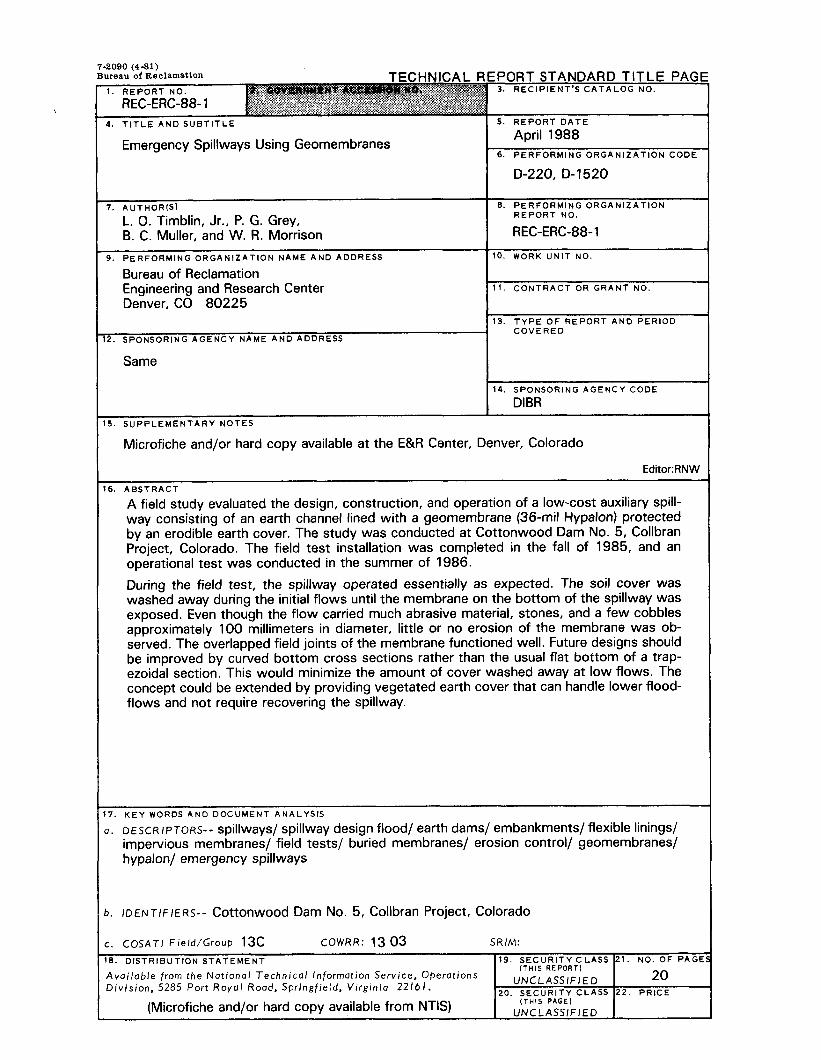
16. ABSTRACT
A field study evaluated the design, construction, and operation of a low-cost auxiliary spill- way consisting of an earth channel lined with a geomembrane (36-mil Hypalon) protected by an erodible earth cover. The study was conducted at Cottonwood Dam No. 5, Collbran Project, Colorado. The field test installation was completed in the fall of 1985, and an operational test was conducted in the summer of 1986.
During the field test, the spillway operated essentially as expected. The soil cover was washed away during the initial flows until the membrane on the bottom of the spillway was exposed. Even though the flow carried much abrasive material, stones, and a few cobbles approximately 100 millimeters in diameter, little or no erosion of the membrane was ob- served. The overlapped field joints of the membrane functioned well. Future designs should be improved by curved bottom cross sections rather than the usual flat bottom of a trap- ezoidal section. This would minimize the amount of cover washed away at low flows. The concept could be extended by providing vegetated earth cover that can handle lower flood- flows and not require recovering the spillway.
17. KEY WORDS AND DOCUMENT ANALYSIS
1. DESCRIPTORS-- spillways/ spillway design flood/ earth dams/ embankments/ flexible linings/ impervious membranes/ field tests/ buried membranes/ erosion control/ geomembranes/ hypalon/ emergency spillways
). IDENTIFIERS-- Cottonwood Dam No. 5, Collbran Project, Colorado
:. COSATI Field/Group 13c COWRR: 13 03 SRIM:
6. DISTRIBUTION STATEMENT 19. SECURITY CLASS 21. NO. OF PAGE:
Available from the National Technical Information Service, Operations (THIS REPORT)
20 Division. 5285 Port Royal Road, Springfield. Virginia 22161.
UNCLASSIFIED 20. SECURITY CLASS 22. PRICE
(Microfiche and/or hard copy available from NTIS) (THIS PAGE1
UNCLASSIFIED

REC-ERC-88-1
EMERGENCY SPILLWAYS USING GEOMEMBRANES
by
L. 0. Timblin, Jr.
P. G. Grey
B. C. Muller
W. R. Morrison
April 1988
Applied Sciences Branch Division of Research and Laboratory Services Concrete Dams Branch Division of Dam and Waterway Design Engineering and Research Center Denver, Colorado
UNITED STATES DEPARTMENT OF THE INTERIOR * BUREAU OF RECLAMATION

ACKNOWLEDGEMENTS
Cooperation provided by the regional office in Salt Lake City, Utah, and field offices at Grand Junction and Collbran, Colorado, is appreciated. In particular, the contributions of Bob Brewster, Ron Johnston, and Mike Thomas from the Salt Lake City Office; Don Wiltse, Collbran; and Fred Crabtree, Grand Junction Proj- ects Office are especially appreciated.
Special recognition is given to John G. Starbuck who assisted in the design work.
Special thanks are given to the following E&R Center personnel who assisted on the project: Clair Haverland, Warren King, Roman Koltuniuk, John Schaffer, and John Swihart.
As the Nation’s principal conservation agency, the Department of the Interior has responsibility for most of our nationally owned public lands and natural resources. This includes fostering the wisest use of our land and water resources, protecting our fish and wildlife, preserv- ing the environmental and cultural values of our national parks and historical places, and providing for the enjoyment of life through out- door recreation. The Department assesses our energy and mineral resources and works to assure that their development is in the best interests of all our people. The Department also has a major respon- sibility for American Indian reservation communities and for people who live in Island Territories under U.S. Administration.
The research covered by this report was funded under the Bu- reau of Reclamation PRESS (Program Related Engineering and Scientific Studies) allocation No. SO-5, “Flexible Membrane Emergency/Auxiliary Spillways.”
The information contained in this report regarding commercial prod- ucts or firms may not be used for advertising or promotional purposes and is not to be construed as an endorsement of any product or firm by the Bureau of Reclamation.
ii
-- -

CONTENTS Page
Introduction... . . . . . . . . . . . . . . . . . . . . . . . . . . . . . . . . . . . . . . . . . . . . . . . . . . . . . . . . . . . . . . . . . . . . . . . . . . . . . . . . . . . . . . . . . . . . . . . . . . . . . . . . . . . . . . . . . . . , . . . . . . . . . . 1
Summary . . . . . . . . . . . . . . . . . . . . . . . . . . . . . . . . . . . . . . . . . . . . . . . . . . . . . . . . . . . . . . . . . . . . . . . . . . . . . . . . . . . . . . . . . . . . . . . . . . . . . . . . . . . . . . . . . . . . . . . . . . . . . . . . . . . . 1
Background . . . . . . . . . . . . . . . . . . . . . . . . . . . . . . . . . . . . . . . . . . . . . . . . . . . . . . . . . . . . . . . . . . . . . . . . . . . . . . . . . . . . . . . . . . . . . . . . . . . . . . . . . . . . . . . . . . . . . . . . ......... 1
Initial investigation . . . . . . . . . . . . . . . . . . . . . . . . . . . . . . . . . . . . . . . . . . . . . . . . . . . . . . . . . . . . . . . . . . . . . . . . . . . . . . . . . . . . . . . . . . . . . . . . . . . . . . . . . . . . . . . . . . . . . . 2
Field study . . . . . . . . . . . . . . . . . . . . . . . . . . . . . . . . . . . . . . . . . . . . . . . . . . . . . . . . . . . . . . . . . . . . . . . . . . . . . . . . . . . . . . . . . . . . . . . . . . . . . . . . . . . . . . . . . . . . . . . . . . . . . . . . . . 2
Design considerations . . . . . . . . . . . . . . . . . . . . . . . . . . . . . . . . . . . . . . . . . . . . . . . . . . . . . . . . . . . . . . . . . . . . . . . . . . . . . . . . . . . . . . . . . . . . . . . . . . . . . . . . . . . . . . . . . . 2
Operational test at Cottonwood Dam No. 5.. . . . . . . . . . . . . . . . . . . . . . . . . . . . . . . . . . . . . . . . . . . . . . . . . . . . . . . . . . . . . . . . . . . . . . . . . . . . . . . . . . 3
Laboratory tests . . . . . . . . . . . . . . . . . . . . . . . . . . . . . . . . . . . . . . . . . . . . . . . . . . . . . . . . . . . . . . . . . . . . . . . . . . . . . . . . . . . . . . . . . . . . . . . . . . . . . . . . . . . . . . . . . . . . . . . . .. 5
Bibliography . . . . . . . . . . . . . . . . . . . . . . . . . . . . . . . . . . . . . . . . . . . . . . . . . . . . . . . . . . . . . . . . . . . . . . . . . . . . . . . . . . . . . . . . . . . . . . . . . . . . . . . . . . . . . . . . . . . . . . . . ........ 20
TABLES Table
1 Material properties of Hypalon . . . . . . . . . . . . . . . . . . . . . . . . . . . . . . . . . . . . . . . . . . . . . . . . . . . . . . . . . . . . . . . . . . . . . . . . . . . . . . . . . . . . . . . . . . . 3 2 Water immersion test results for 36-mil Hypalon . . . . . . . . . . . . . . . . . . . . . . . . . . . . . . . . . . . . . . . . . . . . . . . . . . . . . . . . . . . . . . . . . 6 3 Outdoor exposure test results for 36-mil Hypalon . . . . . . . . . . . . . . . . . . . . . . . . . . . . . . . . . . . . . . . . . . . . . . . . . . . . . . . . . . . . . . . 7
FIGURES
Figure Overall plan view of Cottonwood Dam No. 5 and emergency spillway .................................. Profile of the spillway showing locations of geomembrane blankets.. .................................... Typical cross section of spillway ........................................................................................ Termination of the upstream and downstream end of the geomembrane blankets ................. Gradation of soil cover ...................................................................................................... Preparation of subgrade before geomembrane installation in spillway.. .................................. Section of geomembrane installed in spillway before backfilling and compacting
anchor trenches ............................................................................................................ Downstream end of geomembrane-lined spillway ................................................................ Looking upstream at geomembrane-lined spillway ............................................................... Placement of soil cover to protect geomembrane from the elements and mechanical
damage ........................................................................................................................ Completed spillway ........................................................................................................... Placement of sandbags in spillway crest to form an artificial barrier ...................................... Sandbags in place.. ........................................................................................................... Flow over spillway crest during operational test .................................................................. Flow at downstream end of spillway .................................................................................. Spillway during operation ................................................................................................... Looking upstream at geomembrane-lined spillway after operational test.. .............................. Downstream end of geomembrane-lined spillway after operational test ................................. Tear in geomembrane ........................................................................................................ Overlap seam after operational test ....................................................................................
8
i 10 11 12
8 9
10
12 13 13
11 12 13 14 15 16 17 18 19 20
14 14 15 15 16 16 17 17 18 18 19
. . . III


The use of flexible membrane lined emergency spill- ways is being shown to be a feasible solution to the problem of inadequate spillway capacity for some existing embankment dams. The USBR (Bureau of Reclamation) has completed the initial stage of an investigation on the use of membrane emergency spillways for low-head structures (< 15 m). This study, initiated in 1981, involved the installation of an 80-meter-long flexible lining on a spillway of an earth dam located near Grand Junction, Colorado, at an elevation of 3050 meters. The field test installa- tion was completed in the fall of 1985, and an op- erational test was conducted in the summer of 1986. Long-term studies on this installation are continuing. These studies involve the removal of test coupons of the flexible lining for durability studies and behav- ioral observations of the spillway both during and between the passage of flows throughout the re- search period.
SUMMARY
A field study evaluated the design, construction, and operation of a low-cost spillway consisting of an earth channel lined with a geomembrane protected by an erodible soil cover. The concept was tested on a 5.8-meter-high by 137-meter-wide dam in Colorado. In 1986, construction was completed and a field test performed to evaluate the behavior of the erodible soil cover and the operation of a geomembrane-lined channel. During the field test, the flow was about 0.7 m3/s with a maximum ve- locity of 8 m/s.
In the field test, the spillway operated essentially as expected. During the initial flows over the spillway, the soil cover was washed away until the membrane on the bottom of the spillway was exposed. Even though the flow carried much abrasive material, stones, and a few cobbles approximately 100 milli- meters in diameter, little or no erosion of the mem- brane was observed. The overlapped field joints of the membrane functioned well. Future designs should be improved by curved bottom cross sections rather than the usual flat bottom of a trapezoidal section. This would minimize the amount of cover washed away at low flows. The concept could be extended by providing vegetated earth cover that can handle lower floodflows and not require recovering the spillway.
Before construction, 2-year water immersion and outdoor exposure tests were conducted on samples of the membrane to be used in the field study. Al- though some properties changed, these changes were considered insignificant. This is because there
was no indication of progressive deterioration with time and because the changes were consistent with those that occur with the Hypalon curing that takes place in the first few months of exposure.
BACKGROUND
In a 1981 survey of non-Federal dams, 81 percent had dam safety deficiencies because their spillways were not adequate to pass the estimated maximum floods. This reflects the difference between present- day design flood criteria and the criteria used when the dams were constructed [ 1, 2, 31’.
Embankment dams are particularly sensitive to failure caused by overtopping, both during construction and while in service. There have also been many cases where dams were overtopped because of gate failure [4]. Because the cost of a conventional concrete- lined spillway or even a rock-lined compacted-earth spillway would be prohibitive for some reservoirs, an attractive approach would be to provide a geomem- brane-lined emergency spillway. The geomembrane would be covered with a protective soil cover until the spillway is needed for operation. At the beginning of emergency spillway operation, the soil cover would be washed away, and the membrane lining would carry the flow, protecting the embankment from erosion [5]. The basic concept is that with both existing and new embankment dams, a low-cost spillway could be constructed on or adjacent to the embankment. The function of the membrane during operation is to provide a watertight barrier that pro- tects the embankment from erosion.
Narrow canyons present special problems for emer- gency spillways. If there is not an alternative valley available for an emergency discharge, the flow must be through the dam, over the dam, or tunneled around the dam through the abutment. With con- ventional engineering, any of these alternatives could encounter difficult engineering problems or extreme costs. For an embankment dam, a geomembrane- lined emergency spillway over the embankment may offer a cost-effective alternative to a conventional design. As with such spillways constructed in the adjoining abutment, the geomembrane would con- tain the flow and protect the embankment from ero- sion. A protective soil cover would be used to avoid mechanical damage when not in use and promote long-term durability. This potential use of geomem- brane-lined spillways in narrow valleys is applicable both where the existing spillway is inadequate to convey the infrequent large floodflows or where an emergency spillway is required to supplement the operational spillway.
l Numbers in brackets refer to entries in the bibliography.

INITJAL INVESTIGATION
The geomembrane must be strong enough to resist damage from hydraulic forces and debris during op- eration. It also must have chemical properties that provide very long-term durability. Significant ad- vances have been made in recent years in the man- ufacture of flexible membrane materials suitable for a wide range of water resources engineering work. Extensive work has been performed to identify the important properties of the many excellent materials now available. Laboratory testing, field studies, and observations of these materials in place have pro- vided guidance for the selection of durable materials [6, 71. Encouraging studies have also been done in France and the U.S.S.R. [8, 91.
The USBR investigation included an evaluation of the feasibility of various applications for low-head struc- tures [ 10, 111. The initial potential applications in- clude existing low-head structures that have inadequate spillways, new low-head earth dams, low-head dikes on large reservoirs, saddles suitable for emergency overflow where erosion could be a problem, and improvements to emergency/auxiliary spillways. In 1983, a geomembrane was installed as part of the emergency fuseplug spillway at the Lake Byllesby Dam in southern Minnesota [ 121.
Ultimately, the investigation is intended to produce design procedures, materials specifications, con- struction procedures, and cost data to assist in the selection, design, and construction of geomembrane emergency/auxiliary spillways for low-head struc- tures. With the experience gained in studying low- head structures, the potential of geomembranes for high-head structures can be evaluated.
FIELD STUDY
The rehabilitation of Cottonwood Dam No. 5, Coll- bran Project, Colorado, offered an excellent oppor- tunity for a field study. Some of the questions addressed in this study are:
1. When membranes are used on slopes, what ef- fect does the water velocity have on the membrane? Does drag produce a tensile force on the membrane exceeding its strength? Does the flow uplift the sheet from its foundation?
2. What are the effects of abrasive sands and ma- terials on the membrane?
3. What are efficient methods of anchoring the membrane along the sides and in the transverse direction?
4. What is the minimum depth of cover material re- quired to protect the membrane from the elements and from accidental, mechanical, and animal damage. What is the best type of cover material to use?
5. Would erosion of the cover material during op- eration pose a serious problem for downstream hy- draulic structures and machinery?
6. What affect does high water velocity (4 to 5 m/s) have on the membrane when the sheet is wrinkled after placement?
7. Are special foundation treatments needed before the membrane is placed?
8. What are the effects of aging on the durability and permeability of membranes?
Cottonwood Dam No. 5 is 1 of 17 small private res- ervoirs of the Collbran Project that was constructed on Grand Mesa, near Grand Junction, Colorado. These reservoirs, which are filled during the spring runoff, regulate the runoff from small streams. The stored water is released on demand for hydroelectic power and irrigation purposes.
A USBR SEED (Safety Examination of Existing Dams) report recommended that Cottonwood Dam No. 5 be breached and reconstructed. This recommenda- tion provided the opportunity for the implementation of the flexible membrane emergency spillway study.
DESIGN CONSIDERATIONS
Cottonwood Dam No. 5 is an embankment dam 5.8 meters high and 137 meters wide. The geo- membrane spillway was aligned through the more plastic materials on the right abutment to provide additional erosion protection if needed, as shown on figure 1. The geomembrane-lined channel is 80 meters long and 1 meter deep with a 3.6-meter bottom width, 2: 1 side slopes, and a maximum slope of 0.170. Two grade sills are provided: one at the upstream end of the membrane liner to provide flow control and to prevent piping, the other at the down- stream end to prevent head-cutting back into the spillway. In considering the spillway design, it was clear that the geomembrane should be installed so that each sheet overlaps the adjacent downstream sheet by 1.5 meters. The sheets should not be bonded to each other. This type of construction pro- vides a positive seal for water flowing down its sur- face while providing relief for any hydrostatic pressures under the lining. This type of construction also prevents the accumulated transfer of hydraulic sheer stress from sheet to sheet during operation of
2
^-

the spillway. Design details are shown on figures 2, 3, and 4.
The edges of the liner along the sides and the up- stream edge of the transverse joints were placed in trenches that were subsequently backfilled with compacted soil. A protective cover of 150 milli- meters of noncohesive material was placed over the flexible membrane to protect it from foot, animal, and vehicle traffic. Noncohesive soil materials were se- lected so that they would erode during spillway op- eration [lo]. Gradation of the cover material is shown on figure 5.
With regard to spillway releases, the alignment was chosen so that discharges would not occur along the toe of the dam. Because the flow passes through critical depth at the upstream grade sill, the flow is supercritical over all areas protected by the flexible membrane liner. Energy dissipation was provided by a natural hydraulic jump, which forms over the down- stream channel riprap protection. Riprap was sized to resist displacement caused by velocities associ- ated with the design discharge.
It was considered that cavitation damage might occur downstream from an abrupt change in surface con- dition, such as a seam or wrinkle in the membrane. The most severe condition is a right angle offset into the direction of flow. However, the design velocity, 4.42 m/s, is much lower than the minimum cavitation velocity. Hence, cavitation damage is not expected [ll, 13, 14, 151.
Factors included in selection of the flexible membrane were high tensile strength and flexibility, high punc- ture and abrasion resistance, good impact tear re- sistance, good weatherability, and immunity to bacterial and fungus attack. Two types of lining ma- terials that appear suitable for this application are the fabric-reinforced materials, such as Hypalon and CPE (chlorinated polyethylene) and HPDE (high-density polyethylene). Because of the remote location, small size, and onsite availability of some Hypalon, the ma- terial selected for the field study was 0.9-millimeter- thick reinforced Hypalon sheet, fabricated to 11.6 by 12.2 meters, and 11.6 by 7.0 meters [l l] (table 1).
OPERATIONAL TEST AT COTTONWOOD DAM NO. 5
To obtain the maximum benefit, the field test consists of a two-part program with both a short-term and a long-term phase. The short-term phase concentrates on design and construction factors and an initial as- sessment of the operation of the spillway. Long-term studies cover O&M (operation and maintenance) and geomembrane serviceability.
Table 1. - Material properties of Hypalon.
Property Test method Test value
Gauge (nominal)
Piles reinforcing
Thickness (mm, minimum) 1. Overall 2. Over scrim
Breaking strength - fabric (kN, minimum)
Tear strength (kN, minimum)
1. Initial 2. After aging
Low temperature (‘C)
Dimensional stability (each direction percent change maximum)
Volatile loss (percent loss maximum)
Resistance to soil burial (percent change maximum in original values)
a. Unsupported sheet 1. Breaking strength 2. Elonoation at break 3. Modilus at 100%
elongation
b. Membrane fabric breaking strength
Hydrostatic resistance (Mpa, minimum)
Ply adhesion (each direction kN/m width, minimum)
ASTM D 751
Optical method
ASTM D 751 method A
ASTM D 751 (modified)
ASTM D 2136 3.2-mm mandrel, 4 hour pass
1 hour
ASTM D 1203 method A, 0.36-mm sheet
ASTM D 3083
:i::imm (modified)
ASTM D 751 method A, procedure 1
ASTM D 751 method A, procedure 1
ASTM D 413 machine method we A
Factory seam requirements
Bonded seam strength - ASTM D 751 shear (factory seam, (modified) brztng factor, kN
Peel adhesion (kN/m, ASTM D 413 minimum) (modified)
36 mils (0.81 mm)
1
::i:
0.89
10.5 4.5
-40
2
0.5
0.5
:1
0.11
1.72
1.75
0.712
Ply sep- aration in plane of scrim or 1.75
3

Construction of the spillway was begun by hand plac- ing eight geomembrane blankets that were approx- imately 12.5 meters in width and ranged from 1.5 to 21.4 meters in length [ 151. After placement, the upstream and side edges of the geomembrane blan- kets were secured in l- by 0.5-meter trenches filled with compacted backfill. The protective cover of non- cohesive soil was then placed on the blankets. The entire placement of the membrane and cover material was accomplished between June and September 1985. Because of the high altitude, remote location, and periods of bad weather, construction could be accomplished only a few days at a time during suit- able weather conditions. Photographs taken during construction of the spillway are shown on figures 6 through 10. Figure 11 shows the completed spillway.
The operational test was conducted in July 1986. To provide the necessary reservoir level to conduct the test, the gate to the primary outlet structure was closed and flashboards were installed in a weir in the gate chamber that serves as a service spillway. For the emergency spillway, a total of 41 sandbags were stacked in 5 layers across the inlet channel, increas- ing the effective height of the reservoir above the emergency spillway crest by approximately 0.5 meters. A rope was attached to each sandbag and labeled so that the sandbags could be selectively removed during the test. Placement of the sandbags is shown on figures 12 and 13.
The operational test was conducted for approxi- mately 3% hours. At the beginning of the test, the reservoir level behind the sandbags in the emergency spillways was about 0.3 meters. During the test, the discharge was estimated to be 0.6 to 0.7 m3/s, and the maximum velocity estimated to be 6 to 8 m/s. These velocities are higher than anticipated and may be attributed to a Manning’s number that was lower than the assumed value of 0.015. Consequently, some additional studies should be conducted to ob- tain design data for establishing a Manning’s number for spillways with flexible membrane linings.
The spillway operated essentially as expected, as shown on figures 14 through 18. Early in the oper- ation of the spillway, the soil cover was washed away until the membrane on the bottom was exposed. From then on, gradual erosion of the cover on the sides of the spillway continued for a few centimeters up the sides. Even though the flow carried much ab- rasive material, stones, and a few cobbles approxi- mately 100 millimeters in diameter, little or no erosion of the membrane was observed. Only one small tear, approximately 75 millimeters long, was found, (fig. 19); it was suspected that this occurred during construction. A fist-sized stone found under the membrane at this location was probably respon- sible for the tear. This tear was visible during the
operation of the spillway but did not appear to in- crease in size.
The overlapped field joints of the membrane func- tioned well. Immediately after the test, the over- lapped joints were inspected. The exposed portion of the geomembrane was wet from the flows; how- ever, the portion under the overlap was completely dry (fig. 20). There was no evidence of accumulated tensile strain from one sheet to another. As ex- pected, the membrane was installed with some wrin- kles to help it conform to the subgrade. These wrinkles, did not cause any problems during the op- eration of the spillway.
Specific observations and results of the field test, in terms of the study objectives, are summarized:
1. The flow placed no noticeable serious strain on the geomembrane, and the overlapped joints helped avoid accumulation of tensile load along the spillway. Any uplift pressures were accommo- dated by the overlapped joints. The amount of uplift was minimal.
2. The geomembrane experienced little or no ab- rasive damage from the cover material as it was washed away.
3. The simple method of securing the membrane in 1- by 0.5-meter trenches filled with compacted soil was successful.
4. The soil cover proved successful in preventing mechanical damage to the geomembrane for the 10 months of exposure as a buried membrane lin- ing. The cover was stable on the 2: 1 side slopes.
5. As a precaution, the downstream hydroelec- tric facilities were protected from damage by the soil cover material by bypassing the turbid flow. However, this was necessary for only a few min- utes as the stream quickly cleared up.
6. The velocity exceeded the expected 4 to 5 m/s and reached perhaps 6 to 8 m/s. Even at these higher velocities and with the wrinkled liner damage, distress, or cavitation was not observed.
7. Reesonable care must be taken to prepare the subgrade free of rocks and stones. If suitable ma- terial is not available for construction of the subgrade, a layer of fine-grained material will be needed under the geomembrane.
8. Aging and durability were not problems in the early field test, and none are expected because the normal,early aging observed in the 2-year ma- terials tests shows adequate retention of materials properties.
4

Future designs should be improved by curved bottom cross sections rather than the usual flat bottom of a trapezoidal section. This would minimize the amount of cover washed away at low flows. This concept could be expanded by providing vegetated earth cover that can handle floodflows with minimal ero- sion and not require recovering the spillway after each operation. Studies have recently been com- pleted in England on the reinforcement of steep grassed waterways [16]. This may have application in USBR work, but would depend upon local soil and climatic conditions. To prevent the membrane from being torn by logs, trees, or branches, installation of a log boom upstream of the spillway should be considered.
LABORATORY TESTS
Water immersion and outdoor exposure tests were conducted on samples of the Hypalon liner installed in the spillway.
For water immersion, samples of the 36-mil lining material were placed in laboratory tapwater and tested after 4, 13, 26, 52, 78, and 105 weeks of immersion. The temperature of the running tapwater varied between 10 and 16 “C. The following ASTM tests were conducted on the samples after recon- ditioning at 23 “C and 50 percent relative humidity for a minimum of 40 hours:
No. Test ASTM Test Method
1 Thickness D 751 2 Hydrostatic D 75 1, Method A,
resistance Procedure 1 3 Breaking strength D 751, Grab Method A 4 Tear strength D 75 1, Tongue Tear, Method B 5 Ply adhesion D 431, Machine Method,
Type A Specimens 6’ Bonded seam D 75 1, Grab Method A
strength in shear 7’ Bonded seam D 413
strength in peel
‘Tests conducted on factory seams.
Samples were weighed before and after immersion to determine amount of water absorption. Samples of Hypalon were also placed in the E&R Center out- door exposure test area and tested after 26,52,78, and 104 weeks of outdoor weathering; tests No. 1, 2, 5, and 7 were conducted on the samples.
Results for water immersion are summarized in table 2. Results show minimal changes in physical properties of the Hypalon, including three factory seams. There was some decrease in tear strength (from 162 to 116 Ibf) after 105 weeks of immersion. The amount of water absorption was quite low: a weight gain of only 4.1% (surface dry condition) after 105 weeks of immersion. Outdoor exposure test re- sults (see table 3) indicate, as with water immersion, little change occurred in the Hypalon physical properties.
5

Table 2. - Water immersion test results for 36-mil Hypalon. Sample No. B-7084.
Property Original test method values
Weight gain, % (surface dry) -
Weight gain, % (conditioned) -
Thickness, mils, ASTM D 751 37.4
Hydrostatic resistance, Ibf/irV, 420 ASTM D 751, Method A
Breaking strength, Ibf, ASTM D 751, Grab Method A
254
Q) Tear strength, Ibf, 162
ASTM D 751, Tongue Tear Method B
Ply adhesion, Ibf/in, ASTM D 413, Machine Method Type A Specimens
7.2
‘Bonded seam strength in shear, Ibf, ASTM D 751, Grab Method A
140
*Bonded seam strength in peel Ibf/in, ASTM D 1876
23.0 15.1 -34.3 19.6 -14.8
4-week 13-week 26-week 52-week 78-week
Ialue % change
- 2.91
1.33
36.5 -2.4
121 0
98 -22.0
47 -9.3
6.7 -6.9 7.1 -1.4 6.1
I17 -16.4 1 112 -20.0 151
\
c c
1
1
/alue % change Value % change
36.5
t99
3.02
1.43
-2.4
-7.4
35.7
423
2.89
1.40
-4.5
0.7
174 -31.5 188 -26:0
122 -24.7 133 -17.9
-15.3
7.9
-
Value % change
3.33
1.26
34.6 -7.5
114 -1.4
!35 -7.5
144 -11.1
6.3 -12.5
176 25.7
23.5 2.2
falue % change
35.4
Cl3
!73
Ill
6.8
!lO
23.9
3.44
1.65
-5.3
-1.6
7.5
-31.5
-5.5
50.0
3.9
105-week
dalue % change
4.06
1.90
34.9 -6.7
402 -4.3
274 7.9
116 -28.4
7.3 1.4
162 15.7
24.5 6.5
l Tests conducted on factory seam.

Table 3. - Outdoor exposure test results for 36-mil Hypslon.
26-week 52-week 78-week 1 OCweek Original values Value % change Value % change Value % change Value % change
Thickness, mils, 37.4 35.6 -4.8 35.1 -6.1 35.2 -5.9 34.8 -7.0 ASTM D 751
Hydrostatic resistance, Ibf/in2, 420 421 0 418 -0.5 414 -1.4 417 -0.7 ASTM D 75 1. Method A
Ply adhesion, Ibf/in, ASTM D 413, Machine Method Type A Specimens
7.2 6.3 -12.5 5.4 -25.0 6.0 -16.7 6.4 -11.1
‘Bonded seam strength in 23.0 - - 26.6 15.6 - 23.7 3.0 peel, Ibf/in, ASTM D 1876
l Tests conducted on factory seams.
7
___- . ..-..

SO 0 80 100 180
lJ’1111*111 I I
SCALE OF FEET
Figure 1. - Overall plan view of Cottonwood 5 Dam and emergency spillway.
8

9
-----..-__ ..-

1.0 Feet of loose granular protection
\ 1.0 Riprap on
n K haMinn
Compacted backfill Redwood furring strip (I"X 4”)
DETAIL X NOT TO SCALE
L--u 1.0 I.5 ‘E I. 9994.5
(a) Upstream end of the spillway at the dam crest.
DETAIL Y (TYPICAL)
LCompacted backfill
(b) Typical section along the spillway showing an overlap of approximately 5 feet.
Redwood furring strip 0.5 Feet loose granular protection
DETAIL 2 NOT TO SCALE
l-l I.0
(1% 4’7
3.0 Riprap on I. 5 bedding
(c) Downstream end of the spillway.
Figure 4. - Termination of the upstream and downstream ends of the geomembrane blankets.
10

GRADATION TEST SIEVE ANALYSIS
Dealsnation USBR __
HYDROMETER ANALYSIS EVE OPENING EVE OPENING US. STANDARD SIEVE NUMBERS US. STANDARD SIEVE NUMBERS TIME READINGS TIME READINGS
75 75 37.5 37.5 19.0 19.0 9.5 9.5 4.75 4.75 2.362.0 2.362.0 1.16 1.16 .6 .6 ,425 ,425
.3 .3 .15 .15 ,075 ,075 .037 .037 ,019 ,019 .309 .309 .w5 .w5 .a02 .a02 .OOl ,001
1111I I ll1lI I lllllII I 1 lllllII I 1 lll1lI 1 I I lll1lI I I I lllllI I I I lllllI I I I IllIll I I I IllIll I I I I I 50 50 10 10 5 5 1 1 0.5 0.5 0.1 0.1 0.05 0.05 0.01 0.01 0.005 0.005 0.001 0.001
DIAMETER OF PARTICLE IN MILLIMETERS
FINES
Figure 5. - Gradation of soil cover.

Figure 6. ~ Preparation of subgrade before geomembrane installation in spillway.
P801-D-81368
Figure 7. -Section of geomembrane installed in spillway before backfilling and compactinganchor trenches. P801-D-81369
12

Figure 8. -Downstream end of geomembrane-lined spillway. Note concrete cutoff wall.P801-D-81370
Figure 9. -Looking upstream at geomembrane-lined spillway. P801-D-81371
13

Figure 10. -Placement of soil cover to protect geomembrane from the elements andmechanical damage. P801-D-81372
Figure 11. -Completed spillway. P801-D-81373
14
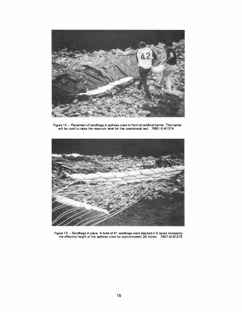
Figure 12. -Placement of sandbags in spillway crest to form an artificial barrier. This barrierwill be used to raise the reservoir level for the operational test. P801-D-81374
Figure 13. -Sandbags in place. A total of 41 sandbags were stacked in 5 layers increasingthe effective height of the spillway crest by approximately 20 inches. P801-D-81375
15

Figure 14. -Flow over spillway crest during operational test. The flow was estimated tobe 0.6 to 0.7 m3/s at a maximum velocity of 6 to 8 m/s. P801-D-81376
Figure 15. -Flow at downstream end of spillway. P801-D-81377
16

Figure 16. -Spillway during operation. P801-D-81378
Figure 17. -Looking upstream at geomembrane-lined spillway after operational test.PBO1-D-B1379
17

Figure 18. -Downstream end of geomembrane-lined spillway after operational test.P801-D-81380
Figure 19. -Tear in geomembrane. This tear may have occurred during the original in-stallation. The material was in excellent condition after the operational test with onlyseveral small areas exhibiting some abrasion damage. P801-D-81381
18

Figure 20. -Overlap seam after operational test. The geomembrane below the overlapwas dry. P801-D-81382
19

BIBLIOGRAPHY
[l] “Recommended Guidelines for Safety Inspec- tion of Dams,” Office of the Chief of Engineers, Department of the Army, Washington, D.C., 1975.
[2] “FEMA Forum,” Federal Emergency Manage- ment Agency, Washington, D.C., July 1982.
[3] “Dam Safety Practices and Concerns in the United States,” U.S. Committee on Large Dams, Boston, MA, April 1982.
[4] Londe, M. Pierre, “Lessons from Earth Dam Failures,” News and Views, British National Com- mittee on Large Dams, London, August 1983.
[5] Timblin, L. 0. Jr., “Comments on the Use of Plastic or Elastomeric Membranes,” Transac- tions of the Fourteenth International Congress on Large Dams, vol. V, p. 674, International Com- mission on Large Dams, Paris, May 1982.
[6] Standard 54, “Flexible Membrane Liners,” Na- tional Sanitation Foundation, November 1983.
[7] Morrison, W. R., and John G. Starbuck, “Per- formance of Plastic Canal Linings,” Bureau of Reclamation Report No. REC-ERC-81-1, January 1984.
[8] Kozoreozva, I. M., “Evaluation of Energy Dis- sipation on Sprawling Membrane Spillways,” Novachersassk Institute of Reclamation Engi- neering, U.S.S.R. December 12, 1977.
[9] Cassard, A., F. Kern, and G. Mathieu, “Use of Reinforcement Techniques in Earth Dams,” Pro- ceedings of International Conference of Soil Re-
inforcement, pp. 229-233 vol. 1, Paris, March 1979.
[lo] Timblin, L. O., Jr., Peter G. Grey, John G. Star- buck, and Ronald K. Frobel, “Flexible Membrane Emergency Spillway,” Dam Safety and Rehabili- tation - Fourth Annual USCOLD Lecture, U.S. Committee on Large Dams, pp. 3-l to 3-13, Bos- ton, January 1984.
[l l] Timblin, L. 0. Jr., Peter G. Grey, and John G. Starbuck, “Flexible Membrane Lining for Emer- gency Spillways,” Proceedings International Conference on Geomembranes, Industrial Fabrics Association International, vol. I, pp. 133-l 39, June 20-24, 1984.
[12] Larson, John R., “Geosynthetics Used to In- crease Dam’s Spillway Capacity,” Geotechnical Fabrics Report, July/August 1987.
[13] Rouse, Hunter, “Engineering Hydraulics Pro- ceedings of the Fourth Hydraulics Conference,” John Wiley and Sons, pp. 29-31, New York, NY, 1950.
[14] Hamilton, W. S., “Preventing Cavitation to Hy- draulic Structures,” Water and Power Dam Con- struction, November, December 1983.
[15] Timblin, L. O., Jr., “The Use of Geomembranes for Emergency Spillway,” Water Power and Dam Construction, December 1985.
[16] Hewlett, H.W.M., L.A. Buarman, M.E. Bramley, and E. Whitehead, “Reinforcement of Steep Grassed Waterways,” Construction Industry Re- search and Information Association, Technical Note 120, London, England, 1985.
20 QU.6.. GOVERNMENT PRINTING OmcE:1994-641-096

Mission of the Bureau of Reclamation
The Bureau of Reclamation of the U.S. Department of the Interior is resoonsible for the development and conservation of the Nation’s water resources in the Western United States.
The Bureaus original purpose “to provide for the reclamation of arid and semiarid lands in the West” today covers a wide range of interre- lated functions. These include providing municipaland industrial water supplies; hydroelectric power generation; irrigation water for agricul- ture; water quality improvement; flood control; river navigation; river regulation and control; fish and wildlife enhancement; outdoor recrea- tion; and research on water-related design, construe tion, materials, atmospheric management, and wind and solar power.
Bureau programs most frequently are the result of close cooperation with the U.S. Congress, other Federal agencies, States, local govern- men ts, academic institutions, water-user organizations, and other concerned groups.
A free pamphlet is available from the Bureau entitled “Publications for Sale.” It describes some of the technical publications currently available, their cost, and how to order them. The pamphlet can be obtained upon request from the Bureau of Reclamation, Attn D-922, P 0 Box 25007, Denver Federal Center, Denver CO 80225-0007.