Embed Size (px)
Citation preview

.dio Telegraphy
.dio Telephony
ire and Cable egraphy
ire and Cablr. lephony
mdcast insmission
rrier nsmission
am nsmission
rine Radio
'ce Radio
!ronautical Radio
le vision
-simile
SUBSCRIPTION
$3.00 YEARLY
u n cation,. Broadcas
Engineering
JUNE, 1935
The Journal of World Communication www.americanradiohistory.com
f0)ApRtTC CORPORHTIOI!
of )°buv'r elot MICROPHONES icrophone for every urpose e.
PERFECT REPRODUCTION and GREAT VALU combined in these mikes PROVE THIS FOR YOURSELF AT NO COST OR OBLIGATION
We believe that we have the finest microphones available today, regardless of price] That's why we will send any one of our models to any responsible broadcaster for a TWO WEEKS' FREE TRIAL I No deposit, no obligation, no strings attached. You simply return the microphone if you don't agree that it's the greatest value available today. PERFECT DEFINITION achieved. Instead of just a general effect of music, each instru- ment is clearly defined. Also, the specially hand -hammered ribbon is unaffected by even a 40 mile gale ... Learn what these top -notch microphones can do. Don't hesitate. There's no obligation. Write us on your business letterhead ...NOW! FOR ANNOUNCING
AND REMOTE
signed for flux Nickel are used . .
powerful than even bolt. Since this micr has no peaks, it gives perfect lifelike reproduction (not me- chanical) and does not tire listener Eliminates accous feed -back in P. A work Model RB -M can be used for both speech and musc Excellent for remote work.
ENGINEERS SAY:
UNEXCELLED FOR MODEL STUDIO USE '_ = S R - 8 0
C7CCCOffCf C7CCCCCfoC C.CCfCCCCC- ,-foeccoce C,CCCCfCCC C^CCCCCCCC
F(POT BROADCASTING
THE LITTLE VELOCITY WITH UNIFORM OUTPUT
Output uniform with speaker's head at any angle. Output level practically equal to large velocity Frequency re- sponse 60 -750C cycles. Repro- duction lifelilm Eliminates audience noises. Transformer included within microphone case. Rugger construction New chrome aluminum mag- nets used. Weighs only 8
' /t ounces. Size ? /s x 11/4 x l. A
A -C PRE - AMPLIFIER end LINE AMPLIFIER
"Best we have test- ed irrespective of price.
--Replacer three of our old micro. phones in rearm. ble work.'
"After plenty of punishment, still as good es ens:
Easiest way to imprd any installation. PesfeCt'' fidelity. No background noises. No resonant peaks
Can be placed up to 2000 feet from amplifier with- out any appreciable loss.
Completely shielded. Elastic coupling absorbs shocks and vibrations.
Frequency response, 30 to 000 CPS. (Max. dil rib I Output, -64 db
-kup angle 120' on front 120' on back side
Can be changed to order.) Output impedance 50 to 200 ohm. Other val- ues if requested. Not af- fected by temperature, pressure, or humidity.
NEW! Illustrated Bulletins 1.2 -3. Write for them now.
THORCUGHLY S H I E L D E D 6 GUAFANTEED H U N I L E S S
Another great Amperio valut in. eluded o FREE TRIAL o-fer. rte. quinsy =mgt. 30- 14.000 cycles 11 db.). Hum Mee. -100 db. Input and output SO. 200.200 ohms.
AMPERITE Córporation 561 BROADWAY NEI
MPERITE 7-POINT GI/AR
YORK
loaY MICROPHONES TO BE THE GREATEST VALUE IN MICROPHONES A I A
(Cable Address: Alkem. New York)
ILABLE TODAY'
www.americanradiohistory.com

i
tMICROPHONES AND PICKUPS
r r Designed for general use,
Astatic quality crystal in-
struments have, through their continued successful applica- tion to public address, remote control and studio broadcast- ing, become the choice of
ousan ds I1 coil th of radio technicians l in these three fields through- out the world. Send for your literature today!
D -104
Type S
LICENSED UNDER BRUSH DEVELOPMENT CO. PATENTS
Astatic Microphone Laboratory, Inc., Youngstown, O. "Pioneer Manufacturers of Quality Crystal Products"
NEW HAMMARLUND I.F. T PROVIDES SELECTIVITY OR
FIDELITY CONTINUOUSLY VARIABLE SELEC-
TIVITY, from a needle -sharp peak to the eat too required for fidelity - without Meeting tuning.
The transformer, basically, Is the lime- tested Ilammarlund I.F.T. design, with neo triple - type, pie- wound Litz coils and aidlelectric condensers. Plus the startling feature of eon - tlntseusly variable equaling between the coils.
Adjustment of coupling in each transformer may be fixed at any point. or continuously varied by panel -control.
Transformers available for 465 ke. or 173 kr. List price, $5.50 each. Variable -..muslin
mechanism for panel control of uD to four transformers. $2.50 list.
It',it,- !)rpt. CRE -ti for !'etoi.n HAMMARLUND MFG. COMPANY, INC. 424 -438 WEST 33rd STREET, NEW YORK CITY
R A N S F o R
E R S
726O72 nf.071,
JUNE 1935
TATTELITE TESTERS - "tell the tale" Tests for blown fuses, resistors or mulensers. circuits, continuity. r.f. peaks and Icm - tuning and neutralizing transmitters, polarity.' defecti,. spark plugs, etc. 100 uses- pocket size.
Price, with instructions, only a $1.00 bill.
NEON PILOT LIGHTS: For indicating open or closed circuits on remote con- trols, test equipment, motors. heaters. Also dead -fuse Indicators and mountings -described In folder 0 -lt, FUSES and FUSE MOUNTINGS: Precision fuses and 1 for i mmnits, trans- mitters. aircraft. radii.. grid auto -radii..
Write for Technical Catalog 6
LITTELFUSE LABS. Ää. Chicago. III.
for QUALITY REPRODUCTION CONSIDER THE NEW HIGH -FIDELITY PRESTO "INSTANT RECORDER"
Built by skilled craftsmen of the finest materials, the Presto Recorder is con- structed with watch-spring precision.
Note these salient features of the Presto Instant Recorder:
I. Completely portable. 2. Easy to operate -only two con-
trols for operation. 3. Flat within 1.5 db from 20 -12000
cycles. 4. Prices within your reach.
I. Completely portable. * 2. Easy to operate -only two controls operation.
for
3. Flat within 1.5 db from 20 -12000 cycles. 4. Two speeds -331/2 or 78 RPM. 5. Positive overhead feed screw mechanism. 6. Power output -I0 watts. 7. Prices within your reach.
7 EVERYTHING FOR RECORDING 7C . . . FROM A NEEDLE TO A COMPLETE
STUDIO INSTALLATION
Write for latest descriptive bulletin of our equipment and coated discs.
RECORDING CORPORATION 139 West 19th Street, New York, N. Y.
COMMUNICATION AND BROADCAST ENGINEERING 3
www.americanradiohistory.com

JUNE 1935
E DITORIAL
ULTRA -S 11111 I T -WAVE PROGRESS
RAPID ADVANCEMENTS ARE being made in the technique of ultra -short -wave communi- cation, and in the application of the equip- ment to commercial use. The modern so- cial structure calls for an ever -widening communication network, serving numerous agencies. From the engineering point of view, an adequate expansion can take place only in the higher frequency bands.
The now famous "G -Men" of the Fed- eral Government are to have facilities for two -way communication between the nu- merous mobile units and with headquarters stations. Transceivers, or separate trans- mitter and receiver units, are to be used, and these will operate in the ultra- high -fre- quency band. According to reports, this type of service may be extended so as to provide a more ambitious inter- communica- tion network, taking in state police units, with the purpose in mind of the general broadcasting of data on crimes of signifi- cance to law- enforcement agencies in va- rious cities and states. Probably this is to be accomplished through the use of relay stations operating at frequencies that may be intercepted over wide areas, or through the use of regional transmitters operating on definite schedules. In any event, the ultra - short -waves will constitute the backbone of the system.
Ultra- short -wave equipment continues to grow in favor with the police depart- ments throughout the country. A dis- tinct advantage lies in the fact that a one - way communication system can be set up at moderate expense, and later converted to a two -way system, without scrapping the original equipment. The system also lends itself to the tying in of local fire depart- ments and hospitals, with slight additional expense. In this respect, it is also possible to provide industrial plants, theatres, hos- pitals, and large estates remotely located, with automatic fire and burglar alarm sys-
terns capable of transmitting the usual type of alarm signal, on the common frequency employed by the local police department radio system.
There are a myriad uses to which the ultra- short -waves may be put. So far, little has been done in adapting such equipment to marine use. Since an ultra- short -wave transmitter is limited in range to begin with, and may be further limited by a reduction of power, it may serve much the same pur- pose as a lighthouse, but with more advan- tages. For example, such non -directional transmitters installed on ships, and having very short range, would guard against col- lisions during fogs. The same units could be used for voice communication between ships close at hand, but not within hailing distance.
The inexpensiveness, compactness, small weight and economy of the ultra- short- wave equipment makes it particularly suit- able for stationary and mobile short-haul work. There is the possibility, however. that through further advancements in de- sign and operating technique, the present range may be considerably increased. New distance records are being made each month, and in many cases these records have been made without an increase of transmitter power or receiver sensitivity. With a clearer knowledge of the propagation char- acteristics of the ultra -high- frequencies, there is a fair possibility that we may be able to overcome to a large degree the bar- riers of space.
An increase in the range of ultra- short- wave transmitters should make them highly desirable for broadcasting, providing, as they could, true high -fidelity programs, free of interstation interference. But, even with moderate ranges, ultra- high- frequency broadcast stations could function as multi- ple- program feeders for cities by injecting, say, four programs from various chain groups on a single carrier, with 20 percent modulation for each program and the use of volume compression, or by modulating a single ultra- high -frequency carrier with four separate program carrier- frequencies, and using at the receiving end a triple- detec- tion superheterodyne.
4 JUNE COMMUNICATION AND
1935 BROADCAST ENGINEERING
www.americanradiohistory.com

BROADCASTERS and RECORDERS tine
RADIO RECEPTOR DYNAMIC (moving coil)
MICROPHONES for Highest Fidelity
Greatest Sensitivity Extreme Ruggedness
Weatherproof . blastproof . . wide angle pickul. . no back- ground noise . . clue to high amplification can be operated 1000 It. from amplifier . . no change in frequency response in close up talking . . no spring suspension needed for P.A. work . . rea- sonably priced from $33 list up.
Complete data supplied on request. Write on your letterhead.
RADIO RECEPTOR CO., Inc., 106 7th Ave., New York
Broadcasting from the Field TYPE PTR -19
PORTABLE PACK TRANSMITTER and
RECEIVER
Description in May "Communi- cation and Broadcast Engineering"
Write for Bulletin C - -
RADIO TRANSCEIVER LABORATORIES
86 -27 115TH STREET RICHMOND HILL, N. Y.
FREQUENCY MEASURING SERVICE Many stations find this exact measuring service of great value for routine observation of transmitter perform- ance and for accurately calibrating their own monitors.
MEASUREMENTS WHEN YOU NEED THEM MOST
R. C. A. COMMUNICATIONS, Inc. Commercial Department
A RADIO CORPORATION OF AMERICA SUBSIDIARY 66 BROAD STREET NEW YORK, N. Y.
MULTIMETERS nd
Ultra Sensitive Meters Thermo Couples in Vacuo
Wattmeters, Fluxmeters Electrostatic Voltmeters, etc.
THE ONLY TWO PIVOT METERS MECHANICALLY CLAMPED FOR TRANSIT
RAWSON ELECTRICAL INSTRUMENT CO. SCHOOL ST., CAMBRIDGE, MASS.
BRANCH: 91 SEVENTH AVE., NEW VOR'< CITY Representative: E. N. WEBBER, Daily News Bldg., Chicago
JUNE 1935
for EXACTING REQUIREMENTS
Engineer who require high fidelity and ESTRI\ PERFORMANCE- specify. KENYON Laboratory Standard units.
From coast to coast. in esery e mew-vial station line -up. KEN YON units are winning :r national OK for doing a rrnl leader's
Unconditionally Guaranteed fre. guency response of + I db from 30 to 15.000 cycles.
Self shielding coil and core structure plus high permeabllity iron casting allow for maximum shielding and minimum electro- magnetic pick -up.
Write for Catalog No. 1 describing these Trans-
formers in jell. Kenyon Transformer Co.,
Inc. 411 ßo,,. ,,,t t, Ne. York
O I
T R A N S F O R M E R S
MICRO -PRECISION WORKMANSHIP
RESULTS IN
High- Fidelity Reproduction
In a microphone it's per- formance and Bruno knows no compromise! After pears of intensive research and development Bruno engineers again lead the field with a new and improved microphone.
('HECK these characteristics of the new RV-3 I. Mechanical ruggedness and flexibility 2. Frequency response 30 to 14,000 CPS 3. Output level -69 db 4. Highly directional 5. Beautifully executed -fits in with the
demands of modern studios The engineering facilities of Department M are at your disposal.
Complete descriptive data available.
TOOK UNDEE COVER
R TH AND CONVINCE
YOURSELF,
BRUNO LABORATORIES 20 -22 West 22nd Street
NEW YORK, N.Y.
COMMUNICATION AND BROADCAST ENGINEERING
www.americanradiohistory.com

THE NEW WOR 50 K. W. TRANSMITTER
Beacon lights on the towers and station roof of the new WOR station are auto- matically lighted by a Weston PHOTRONn: Cell whenever the light intensity falls below a point of good visibility, thus protecting against plane mishaps.
Another WESTON equipped station!
As in all carefully engineered jobs, standard Weston electrical indicating instruments are used in this new station.
A specially mounted \ \...ton high frequency ammeter measures this new station's high output current as it leaves the transmitter building. At lower left is seen the nitrogen -filled tube through which the concentric transmission line runs underground for 600 feet to the antenna system.
Weston Electrical instrument Corporation. 612 Frelinghtrvsen Avenue, Newark, N. J.
WE STQN nrfrumen&
6 JUNE 1935
COMMUNICATION AND BROADCAST ENGINEERING
www.americanradiohistory.com

COMM \IICAVVON & BROADCAST E \GoOElERll \G
FOR JUNE, 1935
AIR CONDITIONING OF BROADCASTING STUDIOS
By D. A. MYER
Plant Engineer
WESTINGHOUSE KDKA and W8XK
SINCE THE BEGINNING of broadcasting, studios have been the subject of endless experimentation and discussion. It has long been recognized that only the proper design of studios will insure op- timum results from the point of view of the critical radio listener.
At first only the problems of poor acoustics of the studio were recognized by the broadcaster. In more recent years not only has acoustical treatment of the studios been perfected but there has also been introduced the soundproofed type of studio. Studios are now constructed with the walls, ceilings and floors sup- ported on springs and with air space between the studio walls and building walls. They resemble a box within a box and are of the sealed -in type, neces- sitating some form of artificial ventila- tion.
KDKA STUDIOS
In planning new studios for KDKA during the summer of 1934, air con- ditioning was given as much consid- eration as was acoustics or the space to be occupied. Thus in finding adequate quarters for KDKA's new studios many more factors presented themselves for consideration than was the case when the world's first broadcast studios were built for the sanie station.
When on November 2, 1934, Westing- house Station KDKA, celebrated the combined events of the opening of its new quarters in the Grant Building in Pittsburgh. and the beginning of its fifteenth year of continuous daily broad- casts, its studios presented the highest point in radio development covering de-
sign, construction, soundproofing, acous-
JUNE 1935
tical treatment, lighting and air con- ditioning.
The new studios and associated offices of KDKA are on the third floor of a modern office building in downtown Pittsburgh. The studio quarters occupy the entire floor, with the studios being grouped in the central section and flanked by the offices along the outside walls of the building.
The air -conditioning system is of Westinghouse design and is intended to supply only the studios and associated rooms but not the offices. The air - conditioning machinery room occupies one of the inside corner rooms from which air is distributed through ducts to the various studios. Both supply and return ducts are concealed above a sus- pended ceiling over the corridors.
In describing a closed circuit it is
difficult to know where to begin, but the fan might be as good as any other point. This fan handles 7200 cubic feet per minute against a head of approximately 1 -% inches of water pressure, and is of liberal design to minimize noise. The blades are of the backward curved type and the discharge velocity is a little over 1000 feet per minute. Above the dis- charge of the fan is the bank of reheat coils and above them individual ducts are run to each of the principal studios. The duct system is carefully designed and installed to avoid generation and transmission of noise. Just before the air reaches a studio it passes through a
bank of sound- absorbing tubes. These are square tubes, each approximately 8" x 8" x 16 ", formed of heavy wire wrapped outside with sound -insulating material. Enough such tubes are banked
STUDIO "A" -ONE OF THE NEW SOUNDPROOFED STUDIOS OF KDKA WITH FLOATING WALL
CONSTRUCTION. NOTE FRESH AIR SPLAYES ON CEILING, ALSO FLUSH LIGHTING FIXTURES.
COMMUNICATION AND 7 BROADCAST ENGINEERING
www.americanradiohistory.com

together to permit the passage of the required volume of air at a velocity of 600 feet per minute. All supply ducts are securely wrapped with insulation to prevent any possible condensation and to further insulate against the entrance of noise.
The air to the two largest studios enters through mushroom -type outlets in the ceiling while in the others it en- ters through suitable grilles near the ceiling. Air is withdrawn near the floor and passes back to the machinery room through the return system. The return air, upon reaching the machinery room, first passes through the humidifier space. This consists of a large pan built into the duct and containing a steam coil. The pan may be filled with water when additional humidity is desired. An auto- matic steam valve is controlled by a humidistat in the fan casing to hold the water at a temperature which will pro- vide the required relative humidity. The return air system then joins the fresh air and is connected to the housing con- taining the cooling coils. All the air then passes through a double bank of filters after which it passes through the cooling coils. There are four cooling coils provided, two in series and two in multiple. After having its temperature reduced, the air goes to the fan for its next round trip.
Two Westinghouse RW -12 compres- sors supply the necessary refrigeration, one compressor supplying a pair of coils.
DESIGN DETAILS
This outlines very briefly the physical
layout of the system and will serve as a background for a discussion of sonic of the details of design. Ít was stated that the fan circulates 7200 cfm. Of this one -third is drawn from outdoors, and the remainder is re- circulated. Since air must escape from the system. pro- vision is made for discharging air from the smaller rooms into the corridor. The system was designed on assumed out- door summer condition of 90° dry bulb and 73° wet bulb. Studios are to be held under these conditions at 80° and 50 percent average humidity. To ac- complish this the air leaves the cooling coils at a temperature of 57° and must enter the studio at a temperature not below 65 °, even under maximum load conditions. As the load in any room decreases, the temperature of the air must rise to hold a constant room tem- perature. This reaches a maximum of something less than 80° when there is no load at all.
The reheat coils supply the heat as required, and these are connected through motor -operated valves which are under thermostatic control from the studio. The thermostats are of the pro- portioning type. With outdoor tempera- tures of 90° and above. the studios are held at a temperature of 10° below that outside. As the outdoor temperature goes below 90° the differential between indoor and outdoor temperatures de- creases proportionately down to zero at 72 °. In other words, with outdoor temperature of 90° the studios are 80 °. With 81° outdoors, the inside tempera- ture is 76 °, and with 72° or less outside, the inside temperature is 72 °.
8 JUNE 1935
GENERAL VIEW OF AIR - CONDITIONING EQUIPMENT ROOM. COMPRESSORS ARE SHOWN ON THE RIGHT, WITH FIL- TER. AIR COOLING C O I L A N D F A N HOUSING ON THE
LEFT.
Since the big problem is one of cool- ing, the year around, it is desirable to keep the temperature at the fan inlet low and allow the reheat coils to care for the temperature of air supplied to the studios. The tempering coil in the outside air supply is therefore bypassed by an automatic damper. The coil is turned on manually when the outdoor temperature reaches about 10° F. The damper operates, during the winter months, from a thermostat in the fan casing to hold a temperature at that point of 57 °.
The humidifier has been mentioned. This is designed to hold a relative humidity of 40 percent with a tem- perature of 72 °.
ENGINEERING ASPECTS
Thus far, we have spoken of gen- eralities. Now let us be a little more specific and discuss in a brief way the engineering aspects of air -conditioning apparatus and its design. Really there is nothing so particularly difficult or mysterious about the manufacture of artificial weather. There are certain fundamental laws which must be kept in mind and always act to guide the engineer.
First, we can consider air condition- ing in the winter months. During a large part of the time the equipment merely acts as a hot -air heater. In this case fresh air from the outside is heated by steam and circulated throughout the rooms to be heated.
Quite frequently in the winter season the relative humidity of the outside air is very low. On occasions of this kind the steam in the humidifier is turned on and the air absorbs the hot vapor which, in turn, raises the humidity of the studio air. The proper amount of humidity of the treated air, after the steam to the humidifier is turned on, is controlled by the humidistat.
Of course, there are instances, espe- cially during the milder winter days. when it is necessary to actually cool the air in the studio quarters. This occurs when the temperature is mild and the studios have been used for an appre- ciable length of time with possibly a full heat load of persons in the studio quar- ters, either a large cast or visitors. To take care of this condition one or both of the compressors are put into oper- ation and the air temperature reduced. We then have air conditioning as it is generally understood. However, air con- ditioning really means the maintenance of a desired condition of air tempera- ture, humidity, motion, and quality at all times, summer and winter. The cooling and dehumidifying functions are found usually only in very modern in- stallations and these will be discussed in detail.
COMMUNICATION AND BROADCAST ENGINEERING
www.americanradiohistory.com

COOLING AND DEHUM DIFYING
To begin with, we are dealing in terms of heat and we must therefore consider our problem from this angle. Each person with a normal amount of more or less restive activity gives off approximately 400 BTU's per hour. Electric lights radiate 3.4 BTU's per watt per hour. The warm summer air from outside of the building has a certain amount of heat which must be taken out of it, and in addition to this there is a certain transmission loss or leakage which must be overcome. All of the above represents the load against which the compressors are working. Compressors are usually rated in terms of "tons" -equivalent tons of ice melted in 24 hours, there being 12.000 BTU's per hour to a ton.
We learn from the air -conditioning engineers that one pound of air will absorb .24 BTU's per degree tempera- ture of cooling and also that there are 13.5 cubic feet of air in one pound of air. Most air -conditioning plants are so designed to cool approximately 10
degrees below outside temperature, with the difference tapering off to zero when the outside temperature drops to 70° or 72 °. For a temperature change of 10
degrees the absorption will be 10 x .24 or 2.40 BTU's per pound of air. The question of how much air must be cir- culated through the system can be answered !Ay finding the number of BTU's which must be removed from the studio quarters. We first find out how many persons are expected to be in the studio quarters. The number of persons is multiplied by 400 and the "people load" is known. The next will be the light load. This figure becomes familiar after a short time, but if we wish to calculate it we take the total wattage of the electric lights and multiply it by 3.4. This load is ordinarily associated with a constant inasmuch as some of the heat from the lights is usually carried away by the ceiling or walls, depending upon how they are mounted. The transmission load is the next figure, and as the transmission constant for each room is known we multiply the area of walls, floor, and ceiling by their transmission constants and by the tem perature difference to obtain the trans- mission load. The studio load therefore will he the total of the people, the light load and the transmission load, ex- pressed in BTU's, per hour. This figure is then divided by 2.4 and we find the number of pounds of air which must be
circulated through the studio to give a maximum cooling of 10 degrees below outside temperature. As mentioned be- fore. there are 13.5 cubic feet of air per pound. The number of pounds of air is then multiplied by 13.5 and we have the number of cubic feet of air which
JUNE 1935
CUT -AWAY DRAWING OF AIR DUCTS SHOW- ING AIR BAFFLES. BAFFLES ARE MADE UP OF WIRE FORMS WHICH ARE COVERED BY A HALF -INCH LAYER OF CABOT'S QUILT
SOUND -ABSORBING MATERIAL.
the fan must circulate to accomplish the 10- degree cooling. The number of cubic feet obtained represents the air which must be used in cooling the entire studio load. Studio load is not the entire com- pressor load, for the compressors must also remove the heat contained in the outside fresh air. The studio load plus the intake air load represents the com- plete compressor load.
DESIGN DATA
In Table I are given figures for the KDKA studio quarters. The first col- umn shows the area in square feet and is obtained by multiplying the room dimensions.
The second column, headed "K ", is
the transmission load constant, or the leakage to be expected from the various rooms. An ordinary room with solid walls has a high leakage constant and may be as high as .8. Rooms with hollow tile construction, or where air space is
provided, have a much lower constant, on the order of .2, as given in the con- trol booth for Studio A or the audi- tion room. When a room such as the main studio is sound treated, as well as soundproofed, the construction is similar
to a refrigerator, and the room in addi- tion to being soundproof holds its heat for a considerable time due to its ther- mos- bottle effect. It may be seen from this column that our control rooms are not sound treated, and likewise that Studios "A ", "B" and "C" are well treated acoustically.
The next column shows the trans- mission load and is the actual load in BTU's lost through leakage.
The next two columns refer to elec- tric illumination -the first column being the total number of watts required when all the lights in the various rooms are lighted, while the associated column gives the BTU heat load. In this par- ticular case the electric light load is not a true multiple of the total watts times 3.4. As the lights for the studios and audition room are mounted flush with the ceiling an appreciable percentage of the heat is radiated into the space above the studio, which has the effect of low- ering the light load.
The next column indicates the num- ber of people which are expected to be in the various rooms.
The seventh and eighth columns com- prise the people load and are labelled "sensible" and "latent ". If the sensible and latent loads for each room or studio are added it will be found to be the product of the expected number of people times 400.
The adjoining column gives the vol- ume of the room in cubic feet. This may be obtained from room dimensions.
The number of air changes which must be maintained per hour for ade- quate cooling has been estimated for the various rooms as indicated in the col- umn headed "Changes per Hour ".
The air velocity or cubic feet per minute circulated is shown in the last column.
OPERATING COSTS
It is natural that one might wonder as to the cost of operating a plant the size of the one under discussion. The new studios of KDKA were opened No- vember 2, 1934, and the air- conditioning
TABLE I
é Le
Studio A 3,870 .06 4,250
Control A 534 .2 590
Studio B 3,490 .06 3,840
Control B 534 .2 590
Observers' A 640 .2 720
Observers' B 578 .2 635
Studio C 1,534 .06 1,700
Control C 514 .2 565
Trans. Studio 640 .2 700
Speakers' Studio 884 .2 970
Speakers' Control 12995 2 1,3300 Audition
Control Master 1,530 .2 1,685
Totals and Average. 16.591 .2 18,285
Ó ;
Z i
á 4 =
a,d
4.800 10,200 80 16,000 400 680 4 800
4,800 10,200 PO 16,000 400 680 4 800
1,300 1,200 30 6.000 1.300 1.000 30 6,000 1.200 680 20 8,000
400 510 4 800
400 700 4 800 400 1.100 5 1,000 200 270 4 400
1,200 2.500 15 3,000 1,200 2.700 4 800
1,200 32.420 2.112 60,400
16,000 14,400 10 2.400 800 1.062 734 137
16,000 12,560 10.7 2.240 800 1.062 744 137
6.000 1.560 20 520 6,000 1.500 20 500
8,000 3,709 11 680 800 789 9.5 125
800 1.080 8 144 1,000 1.655 7% 200
400 330 12 66 33X17 3.751) 7.6 -175
800 3.587 4.6 275
60.400 47.144 9.5 7,899
COMMUNICATION AND BROADCAST ENGINEERING
www.americanradiohistory.com

equipment was of course put into use on that date. From the start detailed records have been kept as to the cost of operating, the average cost of the first four months being $128.00 per month. In analyzing and prophesying yearly costs of operation several things must be kept in mind.
The air -circulating fan operates con- tinuously during all seasons of the year inasmuch as the changes of air in the studio quarters depend upon the action of this fan. The fan at KDKA is in operation approximately eighteen hours per clay. It is driven by a 3 -hp motor. The power costs of the fan therefore should be segregated from the total electrical power bill in order to obtain the power figures for the compressor.
There are two compressors associated with this installation, each being driven by a 20 -hp motor.
Water is used to cool the compressors as the heat taken from the studios is in turn removed by the circulating water. In the case of the KDKA installation the water is wasted. In larger installa- tions it probably would be better to pro- vide for a closed system, cooling the water by means of condensers and there- by permitting its use over and over again. As is to be expected, the water consumption follows the general trend of electrical power. This is obvious when we consider that above the power required for the fan. any additional power used would be for the compres- sors and during long periods of com- pressor operation it follows that water will be used for cooling. During the summer months the ratio of water consumption to power is increased, due to the fact that the temperature of city water is higher and a greater flow of
water is required to obtain the same degree of cooling.
Generally speaking, the steam con- sumption also follows the same trend, as steam must be used for raising the tem- perature of the air from 57° to 72° before the air is returned to the studio.
Table II gives an analysis of the operating costs for the KDKA system for the first four months of operation.
Perhaps the only thing unusual in these figures is the apparently low steam consumption for November and Decem- ber. The steam costs for the period would have been more equalized if it were not for the fact that climatic con- ditions in the Pittsburgh area were very severe and required the use of steam in the preheat coils twenty -four hours a day. In addition to this, the relative humidity of the outside air was ex- tremely low and the humidifier was used a large majority of the time during Jan - urary and February.
It is, of course, to be expected that the summer months will represent the period of most complete and constant use of the air -conditioning apparatus, but the increase in cost will not be di- rectly proportional to the increased hours of operation, inasmuch as electric power and steam consumption will fall into other brackets, or billing blocks, tending to retard accelerated costs.
The renewal cost for spun -glass filters is perhaps a little higher at KDKA than would be expected from stations in other localities. Pittsburgh being an indus- trial center maintains its national rep- utation of being a smoky city. The fact that the air filters at KDKA had to be changed rather frequently is a tribute to the filters and stands as evidence that
TABLE II
Electric Power November 1,660 KWH $35.35 December 1,200 " 27.60 January 1,590 " 34.66 February 1,330 31.65
November December
Compressor Fan 551 KWH = $11.73 1,109 KWH
12 = 28 1,188 = =
$23.62 27.52 January 402 " = 8.76 1,188 " = 25.90
February 221 = 5.26 1,109 " = 26.39 Water Consumption
November 13,900 Gal $2.78 December January February
6,100 " 8,000 .,
6,000 ,.
1.22 2.49 2.09
Steam Consumption November 50.100 Lbs $56.35 December 87,100 92.42 January 107,700 " 112.50 February 108,400 " 113.19
Total Monthly Cost Air Filters Elec. Power I1'aler Steam Total November $5.00 $35.35 $2.78 $56.35 $99.48
December 5.00 7.60 1.22 92.42 12624 January . 5.00 34.66 2.49 112.50 154.65 February 5.00 31.65 2.09 113.19 151.93
10 JUNE 1935
the filters are removing smoke, soot and dirt from the outside air. MAINTENANCE
The time spent in maintenance is surprisingly small. The air filters must be changed periodically, the length of time between changes depending upon climatic conditions to a certain extent. The procedure of change is merely to slide out the old filters and slip the new ones in place. In some cases it may prove worthwhile to shake the filters, dislodging the dirt, and obtain more use from them. In the case of Pittsburgh where smoky and occasionally foggy weather prevails, we have not found it advisable to attempt to clean the filters.
The rotating equipment is watched and cared for as any other rotating equipment might be. The oil cups on the motor bearings are kept filled with oil and the fan grease cups filled.
The steam gauges of course are noted periodically, as well as the pressure gauges on the compressors. Any serious trouble which might develop, such as a leak of freon refrigerant gas (di -chro- difloromethane) will be taken care of by the service department of the company who installed the equipment. After the apparatus is once installed and pipe joints tightened, a leak of the gas prac- tically never occurs. The pipe -joint bolts should be tightened approximately once a month. A serious leak of gas can of course be detected by the pressure gauge on the compressor. Slight leaks can be determined by using a torch pro- vided for the purpose. The gas is non- explosive, non- poisonous and non -tox- icant. When applying a torch to the joints the flame will show a reddish orange, or possibly blue, when no leak exists. With the presence of the slight- est amount of freon gas the flame will turn a violent green.
CONCLUSION
While air conditioning for small in- stallations perhaps may be considered something new, we are convinced from our brief experience that it has per - mantly established itself as a necessary part of all modern broadcasting studio installations. Its cost of operation is almost trivial when compared to its ad- vantages. As outlined in the fore part of this story, it makes possible the adoption of soundproofed studios and concentrated quarters. It is difficult to place a value on the advantages it affords in having the studio quarters in a location where they are easily acces- sible to clients and artists, as well as an interested general public. It is still more difficult to place any value on both the psychological and physiological favor- able reactions obtained from artists working in studios under the most favorable climatic conditions.
COMMUNICATION AND BROADCAST ENGINEERING
www.americanradiohistory.com

VARIABLE CONDENSER
BREAKDOWN VOLTAGES By RAYMOND L. MOREHOUSE
Engineer,
ALLEN D. CARDWELL MFG. CORP.
THERE IS AN increasing tendency on
the part of variable condenser purchas- ers, both professional and amateur, to demand condensers with certain voltage breakdown ratings. This has led to occasional mis- rating, with the result that even many competent engineers and amateurs are confused by the con- tradictory figures. The trouble is that most of these ratings are calculated on
the basis of the mere air separation be- tween the plates, and many of them do not take into consideration such im- portant factors as plate thickness and shape, operating frequency and also the ratio of inductance to capacitance in the actual transmitter circuit.
AVERAGE BREAKDOWN POINTS
In this connection, prospective users of high- voltage transmitting condensers should be interested in the curves shown in Fig. 1. These represent the average of hundreds of individual tests made on stock condensers of various types and sizes by members of the writer's or- ganization and also by the Bell Labora- tories. They reveal some pertinent facts that apply to all variable air condensers, regardless of make.
All the tested condensers had pol- ished plates with rounded edges. The use of square -edge plates in condensers intended for high- voltage applications is altogether unthinkable, as square -edge plates reduce the flashover voltage as much as 20 percent. This figure is not a mere guess. but is based on actual measurements.
PLATE THICKNESS
The curves are correct for plate thicknesses from about .025 to .062 inch. Thinner plates reduce the rating by S
percent or more, a fact that is not gen- erally appreciated. Fig. 2 explains why this is so. The thinner the plate, the more nearly does its edge approach a sharp point, and of course corona and jumpover effects take place much more readily from points than from rounded surfaces. The comparative bluntness of plate B, as measured against plate A, reduces the sparking tendency consid- erably. The plate thicknesses have been exaggerated a little to show the gen- eral idea.
Design engineers will note that there
JUNE 1935
a 1 ?errent difference between the breakdown voltage of the sanie air gap when the condenser is used first on 515 kc and then on 4000 kc. The first fre- quency is regarded as average for the broadcast and neighboring channels, and the second for the amateur and high- f requency communication bands. No ordinary air -dielectric variable condenser is ever operated on 60 cycles, but the uppermost curve is included as a ?tatter of interest. It shows that there is about 8 percent difference between 60 cycles and 515 kilocycles.
USING CURVES
Practical use of these curves may be made in the following manner. Begin with the dc plate voltage of the tube, multiply by three, and from the chart pick a condenser with that flashover voltage, bearing in mind the approxi- mate frequency the transmitter is to use. This procedure applies to circuits that are keyed for cw telegraphy. If the tube is plate -modulated, use the multiplying factor of four instead of three.
Split- stator condensers, which arc commonly used, have a higher flashover voltage than the air gap alone indicates, as the sections usually are in series in relation to the applied dc voltages. In a series of measurements made on such condensers with air gaps from .07 to .218 inch, the flashover voltage for two sections was from 1.6 to 2.1 times that of one section alone.
The L -C ratio of the plate tuning cir- cuit naturally must also be considered. The higher the inductance, the greater the emf developed across the circuit,
A
Fig. 2
THE THICKER THE CONDENSER PLATE THE
LESS ARE CORONA AND JUMPOVER EFFECTS.
.12 .14 .16 .18 .2 .22 .24.26 .28 .3 Air Gap in Inches
AVERAGE BREAKDOWN VOLTAGES OF AIR
CONDENSER%
and the greater the possibility of con- denser flashover. This undoubtedly ac- counts for some cases of flashover in
transmitters using condensers of ap- parently adequate rating.
EFFECT OF FLASHOVERS
"\\ by worry about occasional flash- overs in an air condenser, with its self - healing dielectric ?" This question is frequently asked by amateurs without much practical operating experience with tube transmitters. The answer is found in the behavior of a vacuum tube operated as an amplifier. When the L -C circuit in the plate is tuned to the same frequency as that of the exciting source on the grid, the plate current assumes a
comparatively low value, say 50 mil- liamperes in a medium- powered tube. Off resonance, however, the plate cur- rent shoots up to several times this value. If the full rated plate voltage has been applied, the tube may readily lose all its emission, or the elements will collapse because of the terrific heat developed by the bombardment of the plate. Cases of tube failure because of careless tuning are quite common.
Now a condenser remains a condenser only so long as its dielectric remains intact. A flashover has the effect of short -circuiting the plates, with the re- sult that the L -C circuit is thrown out of resonance and the tube takes the shock of suddenly- increased plate cur- rent. The condenser itself isn't damaged appreciably. Small pit marks may de- velop at the sparking point, but these are easily polished off.
PROTECTION
The best way to protect expensive transmitting tubes from flashovers is to use condensers of suitable design and to operate the tubes within their rated out- put, or appreciably below it. Plate cur- rent jumps caused by off- resonance con- ditions will then be less serious than with the tube already loaded to the limit.
COMMUNICATION AND BROADCAST ENGINEERING
www.americanradiohistory.com

MAINTAINING AND MEASURING TRANSMITTER FREQUENCY
Part, IV-- Standards of Frequency
IN TILE PRECEDING articles of this series we have described various methods used to control or measure the frequency of radio transmitters. In each case considered, we depended on some other oscillator as a standard of frequency. The ultimate oscillator in this series is called a primary standard. It in turn is measured by comparison with a standard of time. Frequency and time are simply two different ways of describing the same quantity.
The usual form of primary standard is a counting device which automatical- ly counts the number of cycles which occur in a given time. This indicates the average duration of one oscillation, or number of oscillations per second. These averages are taken over long periods, at least a day, in contrast with the few seconds usually spent in ob- taining a comparison of frequency of two oscillators. One must rely upon the careful construction of the oscilla- tor to be sure that the frequency at any instant is the same as the measured average frequency. TYPICAL PRIMARY STANDARD
The usual kind of primary standard is illustrated in Fig. 16. The "counting device" is a series of frequency dividers. One cycle in the output of a divider indicates that ten cycles in the input have been "counted." The piezoelectric oscillator operates at a frequency of 100,000 cycles. This frequency is div- ided by 10 three times successively, pro- ducing an output of 100 cycles. This frequency is then amplified until suf- ficient energy is obtained to drive a
By VICTOR J. ANDREW, Ph.D.
Chief Engineer,
DOOLITTLE & FALKNOR, INC.
synchronous motor. Through reduction gears the synchronous motor drives clock hands. Since the speed of the motor depends directly upon the fre- quency of the piezoelectric oscillator, the clock gains or loses time propor- tionately as the frequency of the oscil- lator is above or below 100,000 cycles.
There are relatively few primary standards of frequency in existence. The one located in the Bureau of Stand- ards in Washington is particularly im- portant. The majority of . transmitters are ultimately measured by comparison with this standard, using the interme- .diate agency of the transmissions from station W W V at the Bureau of Stand- ards. The Rules and Regulations of the Federal Communications Commis- sion prescribe that Bureau of Stand- ards shall be accepted as final authority in the measurement of frequency. An- other government primary standard is located in the central frequency -mon- itoring station of the FCC in Grand Island, Nebraska.
The Bell Telephone Laboratories maintain a primary standard in New York which controls the 4000 -cycle frequency which is transmitted by wire for various uses, such as synchroniza- tion of broadcast transmitters. The General Radio Company has sold sev- eral primary standards. CHECKING STANDARDS
The time indicated by the clock driven by a primary standard of fre- quency is most often checked against time signals from the Naval Observa- tory in Washington, which are trans-
Piezo- electric
Oscillator
Frequency 1OA00.
(t)
Frequency Divider
(2)
Frequency Divider
(3) loo
Fiy.l6
Amplifier 100 Synchronous
Motor Clock
PRIMARY FREQUENCY STANDARD.
2 JUNE 1935
mitted by station NAA. If the clock is found to be gaining 0.1 second per day, since there are 86,400 seconds in a day, it indicates that the frequency of the piezoelectric oscillator is 100,- 000.116 cycles per second, or 1.16 parts in a million above its rated frequency. By using a recorder or stroboscope in comparing the clock with the time signals, a reading with an accuracy of about 0.01 second is obtained.
The time signals from NAA are transmitted automatically by the stand- ard clocks of the Naval Observatory. The Riff ler clocks here have for many years been the nation's standard of time. The standard clocks of Great Britain are located in Greenwich, hence the time basis G. M. T. (Greenwich Mean Time). The Shortt clocks de- veloped in England a few years ago are probably the most accurate timekeepers now available. Several of these clocks have been keeping remarkably accurate time for a number of years in the pri- vate laboratory of Mr. Loomis at Tuxedo Park, N. Y.
The precision of piezoelectric oscil- lators is now of about the same order as that of pendulum clocks, and it seems probable that oscillators can be im- proved more easily than pendulums. Primary frequency standards are likely therefore to eventually replace pendu- lum clocks as standards of time. MEASUREMENT OF TIME
The one ultimate unit of time to which all man -made standards are com- pared is the time of rotation of the earth. Certain systematic variations in the period of rotation are known. If there is a long time variation in the period, it is not known, and in fact it can not be discussed unless one first defines time by something other than the period of rotation of the earth. As- suming that irregularities due to tech- nical difficulties are sufficiently small,
COMMUNICATION AND BROADCAST ENGINEERING
www.americanradiohistory.com

there are now available three experi- mental bases for the measurement of time: (1) The period of rotation of the earth, which involves astronomical forces: (2) the period of a pendulum, which involves the strength of the gravitational field; (3) the frequency of a piezoelectric oscillator, which in- volves neither. The study of the dis- crepencies between these three meas- ures of time forms a most interesting and fundamental branch of science.
The comparison between standard clocks and the period of rotation of the earth is made by astronomers who observe daily the time that a given star passes a given position. The average of
several stars is used.
FREQUENCY COMPARISON
In Fig. 17 we show schematically the complete system which is used in com- paring the frequency of a radio trans- mitter with the frequency of rotation of the earth. The earth produces one cycle per day. The pendulum of the standard clock produces 0.5 cycle per second, which is divided by means of gears so that the hour hand operates
Earth
Beat (I)
Pendulum Divider (I)
Beat (2)
Divider (2)
Oscillator (I)
Multiplier Trans m lter (I)
Receiver Oscillator Divider Multiplier (2) (3) (2)
Fig. 17 Trans- mitter
(2)
COMPLETE SYSTEM FOR COMPARING THE
FREQUENCY OF A TRANSMITTER WITH THE
FREQUENCY OF ROTATION OF THE EARTH.
at 2 cycles per day. The comparison of two time- keepers is actually a case of observing the beat, or difference in frequency between the two.
The first comparison, beat (1), is made by the astronomer who compares the reading of the standard clock with the rotation of the earth. The second comparison. beat (2), is made in the Bu-
reau of Standards, between the stand- ard clock and the primary frequency standard. Oscillator (1) is the piezo- electric oscillator in the primary stand- ard. This oscillator, acting through multiplier (1), controls the frequency of transmitter (1), which is WWV.
The next comparison is made in the radio receiver located in the frequency - measuring laboratory. Here the labora- tory standard is calibrated by use of the WWV signals. The only remaining comparison, which is also made in this receiver, is between the laboratory standard and the remote transmitter (2 ) which is being measured.
CONCLUSION
When it is realized that the knowl- edge of the frequency of a transmitter depends on such a long series of com- parisons, as well as on the frequency stability of each intermediate oscilla- tor, the extreme precision necessary in
the individual steps is evident. If the transmitter frequency is to be meas- ured to one part in one million, the largest error in a single step must be
kept down to approximately one -tenth of a part in one million.
NAB MEETING TO BE HELD IN
COLORADO THE EXECUTIVE COMMITTEE of the Na- tional Association of Broadcasters has announced that its 1935 membership meeting will be held at the Broadmoor Hotel in Colorado Springs, Colorado, on July 6, 7, 8, 9 and 10.
This agreement was reached by President Ward, Treasurer Levy and Managing Director Loucks. The deci- sion follows the recommendations of the membership, as expressed in a reso- lution adopted at the Cincinnati Conven- tion, and by a motion adopted at the De- cember Meeting of the Board of Direc- tors.
This meeting is expected to he of un- usual interest.
NEW AUSTRIAN TELEPHONE SERVICE
VIENNA TELEPHONE subscribers are in- formed by means of the usual "no answer" signal, when the person called is either absent or unable to come to the phone. By means of a new device, the subscriber can leave a message to pros- pective callers that he can be reached by telephone at a certain hour. After the "no answer" or "busy" signal is re- ceived, the caller then hears bell strokes which, according to the number, advise him when the party called will be able to answer the phone. Morning hours are given by single strokes, afternoon hours by double strokes; eight single strokes would indicate that the person called can be reached at 8 a. m., while five double strokes indicate 5 p. m.
This innovation saves repeated calls
JUNE 1935
and brings many advantages to business and professional men and to private in- dividuals who have no one to attend to the telephone while out, or do not wish to he interrupted in their work, sleep or pleasure. The clock -stroke signal is pro- duced by a so- called 'return- advisor," a device which can be attached to every telephone apparatus in Vienna within 8
days on application. Its operation is
simple and the whole service, in addi- tion to an installation fee of 5.70 schil- lings, costs only 2.30 schillings per month. All telephone numbers equipped with the "return- advisor" will be so in- dicated in future telephone directories. (Electrical Division. Department of Commerce.)
TELEVISION IN FRANCE ACCORDING TO TIIE "Wireless World," a Television Committee has been set up in France. It is proposed that television transmissions should take place with 170 -line horizontal scanning at 24 frames per second. The French Postal Administration has ordered an experi- mental television transmitter working on ultra -short waves. (Electrical Review, London.)
RADIO EQUIPMENT OF THE S. S.
"NORMANDIE" Tite S. S "NORMANDIE" is equipped with an ultra- modern radio installation, ac- cording to the Electrical Division, De- partment of Commerce. The planned
installation includes a security station and a commercial station.
The security station, installed on the bridge, will be reserved for service calls and includes the following: A 500 - watt transmitter with continuous alter- nating, modulated and unmodulated wavelengths (3 wavelengths of 600- 800 meters, 3 wavelengths of from 2000 to 2400 meters) ; an emergency trans- mitter with batteries; a receiver for all wavelengths (200 -8000 meters) ; and a
shielded loop aerial radiognometer (200 -3000 meters).
The commercial station installed in
the rear of the ship includes : An 800 -watt transmitter, on 6 wavelengths, of from 2000 to 2400 meters, for tele- graphing to the pilot circuits: a trans- mitter with 7 wavelengths of from 600 to 800 meters with approximately 300 watts, with the antenna on shipboard circuits, and which can be worked on emergency batteries ; a short -wave transmitter for telegraphing, 1800 to 2500 watts on 10 wavelengths, 15 to 120 meters ; a short -wave trans- mitter for telephoning, 1000 to 1400 watts with an 8- wavelength antenna, 15 to 80 meters; a 200 -8000 meter receiver ; a telegraph receiver, 13 to 250 meters; a telephone receiver, 16 to 70 meters; a press receiver 8000 to 23,000 meters; and a loop aerial radiognometer.
It should be noted that each trans- mitter has its independent antenna. This means that there is, then, at least 5 antennae on board the S. S. "Nor - mandie." (Lestrade Brown, Asst. Trade Cotnnlissioner. Paris.)
COMMUNICATION AND BROADCAST ENGINEERING
www.americanradiohistory.com

EVANSVILLE'S NEW TWO -WAY POLICE RADIO Fixes/ 1< 9XEII and Mobile W9XEX, on 30.1 Mew:- may", Provide Good Coverage for Policed Area
TO EVANSVILLE, INDIANA, comes the dis- tinction of being the first city in the country to install the new Western Elec- tric Ultra- High- Frequency, Two -Way Police Radio Communication System.
The fixed station, W9XEH, located on the top floor of the Police Headquar- ters Building, was placed in operation January 8, 1935. This transmitter is a Type 16-A 50 -watt unit operating on a frequency of 30,100 kilocycles.
THE FIXED TRANSMITTER
Mechanically, it consists of a relay rack cabinet 6 feet 11 inches high, 22 inches wide, and 18 inches deep, in which are located several panel mount- ing units. A rear door provides acces- sibility for changing tubes and making adjustments of the equipment. The door is equipped with a safety switch which, when opened, removes all high volt- ages. A fan located in the top of the cabinet provides forced -draft ventila- tion and a filter at the bottom removes dust from the air drawn into the trans- mitter.
OSCILLATOR AND R -F UNITS
The radio -frequency unit contains a crystal -controlled oscillator. The crystal is a Type 4 -A "A -Cut" quartz plate which maintains the carrier frequency, accurate to within .025 percent, with- out the aid of a temperature -control
By ROY E. McCONNELL Chief Engineer, W9XEH
A VIEW OF THE I6A TRANSMITTER. SEATED AT THE CONTROL DESK IS CHIEF ENGINEER MCCONNELL. AT THE LEFT IS OPERATOR MORRIS WITH OPERATOR MOUTOUX AT THE RIGHT.
oven. The frequency of the crystal used is 5016.660 kilocycles. The oscillator tube is a Type 306 -A.
The frequency -multiplier stage uses a 306 -A also. The r -f amplifier stage employs a Type 305 -A, and the final r -f amplifier stage uses a pair of 305 -A's in push -pull. An output fre- quency of 6, 8, or 9 times the crystal frequency can be obtained by proper adjustments of the r -f circuits.
THE MODULATOR
The audio -frequency panel contains three stages of a -f amplification. The first stage uses a Type 247 -A tube. The
14 JUNE 1935
OPERATOR HARPER AT THE CONTROL DESK. SHOWN IS THE RECENTLY INSTALLED WESTERN ELECTRIC 89 -A SPEECH AMPLI- FIER AT THE RIGHT. THE 19 -A STATION RECEIVER IS SHOWN AT THE LEFT AND THE 600 -A MICRO. PHONE IN CENTER.
second or driver stage uses two Type 252 -A's in push -pull and the modulator stage uses two Type 284 -A's in push - pull. High -level Class AB. modulation is employed, modulating the plate and screen -grid circuits of the final r -f am- plifier stage.
The power -supply equipment operates from a 220 -volt, 60 -cycle supply, and consists of two full -wave, mercury - vapor rectifiers for supplying grid bias and plate voltages. The rectifier tubes used are 249 -B's. This equipment, ex- cept for the power transformers which are bolted to the frame, is mounted on a panel in the lower portion of the cabinet. The total power consumed by the transmitter is 1.2 kw when trans- mitting at full power.
METERS
There are seven meters in all, mounted on the front of the cabinet. There is an ac meter for reading supply - line voltage; a dc meter for reading the plate- supply voltage; a radio -frequency ammeter for antenna current ; a 0 to 5 milliammeter for indicating grid cur- rent to the oscillator, doubler, and r -f amplifier stages ; a 0 to 50 milliam- meter for indicating grid current to the modulated amplifier stage; a 0 to 300 milliammeter for reading the total mod- ulated amplifier plate current as well as indicating the individual plate current
COMMUNICATION AND BROADCAST ENGINEERING
www.americanradiohistory.com
to each of the two final amplifier tubes; and a 0 to 300 milliammeter for total plate current to the modulator tubes as well as that of each tube in the audio circuits. By use of several switches as- sociated with the meters, the operator can instantly measure the performance of twelve circuits within the equipment. All tuned circuits can be locked to avoid tampering and to insure permanency of adiustment.
THE ANTENNA
A 100 -foot hollow steel flagpole mounted on top of the Police Head- quarters Building serves as a support for the vertical antenna. A concentric transmission line runs through this pole to the antenna. The line consists of two copper tubes, one within the other, the outer being a little less than an inch in diameter and the inner tube about the size of a pencil. The outer tube is
grounded and the inner tube is insulated from the outer by use of Steatite washers. The antenna portion is a brass tube 22 feet long with a 7 -foot brass tube paralleling it at the lower end. This sets up an electrical effect which prevents current from surging back into the transmission line and maintains a uniform current in the line. The re- maining 15 feet of the brass tube be- comes the actual radiator, being a half - wavelength antenna.
MOBILE TRANSMITTER
One car transmitter has been installed and other installations are to be made in the near future.
The call W9XEX has been assigned to the car transmitter which was placed in operation on March 15, 1935. This transmitter is a Type 18 -A unit. It is
housed in a case 11 inches long, 7 inches high and 6% inches deep. The chassis carrying the apparatus is integral with the front panel and may be easily re- moved from the cabinet for inspection.
For mobile use the filament power is
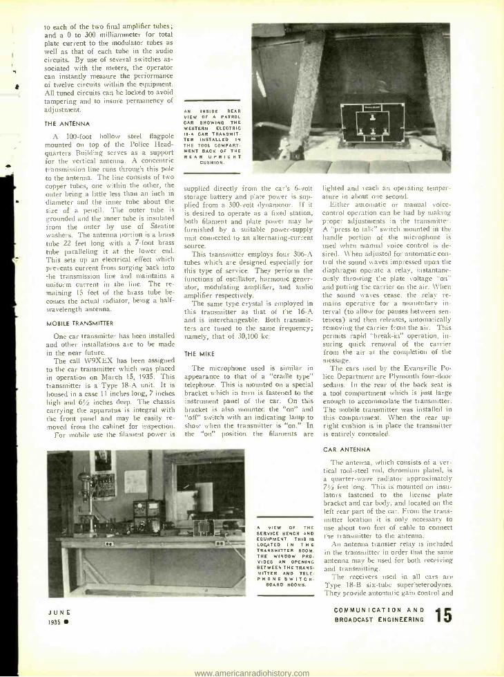
AN INSIDE REAR VIEW OF A PATROL CAR SHOWING THE WESTERN ELECTRIC 18 -A CAR TRANSMIT. TER INSTALLED IN THE TOOL COMPART- MENT BACK OF THE R E A R U P R I G H T
CUSHION.
supplied directly from the car's 6 -volt storage battery and plate power is sup- plied from a 300 -volt dynamotor. If it is desired to operate as a fixed station, both filament and plate power may be furnished by a suitable power- supply unit connected to an alternating- current source.
This transmitter employs four 306 -A tubes which are designed especially for this type of service. They perform the functions of oscillator, harmonic gener- ator, modulating amplifier, and audio amplifier respectively.
The same type crystal is employed in this transmitter as that of the 16 -A and is interchangeable. Both transmit- ters are tuned to the same frequency; namely, that of 30,100 kc.
THE MIKE
The microphone used is similar in appearance to that of a "cradle type" telephone. This is mounted on a special bracket which in turn is fastened to the instrument panel of the car. On this bracket is also mounted the "on" and "off" switch with an indicating lamp to show when the transmitter is "on." In the "on" position the filaments are
JUNE 1935
A VIEW OF THE SERVICE BENCH AND EQUIPMENT. THIS IS LOCATED IN T H E
TRANSMITTER ROOM. THE WINDOW PRO- VIDES AN OPENING BETWEEN THE TRANS- MITTER AND TELE- PHONE SWITCH-
BOARD ROOMS.
lighted and reach an operating temper- ature in about one second.
Either automatic or manual voice - control operation can be had by making proper adjustments in the transmitter. A "press to talk" switch mounted in the handle portion of the microphone is
used when manual voice control is de- sired. When adjusted for automatic con- trol the sound waves impressed upon the diaphragm operate a relay, instantane- ously throwing the plate voltage "On" and putting the carrier on the air. When the sound waves cease, the relay re- mains operative for a momentary in- terval (to allow for pauses between sen- tences) and then releases, automatically removing the carrier from the air. This permits rapid "break -in" operation. in- suring quick removal of the carrier from the air at the completion of the message.
The cars used by the Evansville Po- lice Department are Plymouth four -door sedans. In the rear of the back seat is a tool compartment which is just large enough to accommodate the transmitter. The mobile transmitter was installed in this compartment. When the rear up=
right cushion is in place the transmitter is entirely concealed.
CAR ANTENNA
The antenna, which consists of a ver- tical tool -steel rod, chromium plated, is a quarter -wave radiator approximately 7% feet long. This is mounted on insu- lators fastened to the license plate bracket and car body, and located on the left rear part of the car. From the trans- mitter location it is only necessary to use about two feet of cable to connect the transmitter to the antenna.
An antenna transfer relay is included in the transmitter in order that the same antenna may be used for both receiving and transmitting.
The receivers used in all cars are Type 18 -B six -tube superheterodynes. They provide automatic gain control and
COMMUNICATION AND BROADCAST ENGINEERING
www.americanradiohistory.com

r
1
automatic noise suppression features. They receive their filament voltage direct from the car battery and the plate voltage from a dynamotor.
COVERAGE
Extensive tests have been made with both the fixed and mobile transmitters to determine signal- strength coverage. Evansville is a town of 103,000 people and is situated along the Ohio River. The topography of the eastern part of the city is flat while the western part is exceedingly hilly. The area of the city is 10 square miles. The longest distance east and west is 5 miles, and 4 miles north and south. Reliable two - way communication can be carried on between the fixed and mobile transmitter from any point within the city and up to a distance of 7% miles in any direc- tion from Headquarters. There are, within the city, a number of steel bridges and underpasses, but these do not seem to affect the signals from either transmitter.
A dependable signal can be had from the fixed station up to a distance of 12 miles in any direction. In some direc- tions the signal is readable up to a dis- tance of 22 miles from the station.
At the present time there are twelve cars equipped with receivers. These in- chide the one used by Ira C. Wiltshire, Chief of Police ; three detective cars ;
an armored emergéncy car and seven patrol cars. Two spare receivers, dyna- motors, and generators are carried as extras in the service department to re- place equipment to be serviced.
OPERATING PROCEDURE
Station and operating procedure is more or less standardized. The tele- phone switchboard is located in an ad- joining room and here also is located a Gamewell Fire Alarm tape recorder. Incoming calls are routed to the various departments by the switchboard opera-
A PATROL CAR. SHOWING THE TRANSMIT. TING ANTENNA. FROM LEFT TO RIGHT ARE OFFICER HORNE. CHIEF RADIO ENGINEER McCONNELL. AND OFFICER
YOUNGBLOOD.
tor and the commanding officer of that particular department involved calls Radio, after determining disposition to be made, and gives the order for assign- ment to a particular car or cars. The Radio Operator then transmits the mes- sage. A Western Electric Type 89 -A amplifier with a Type 600 -A double - button microphone is now being in- stalled in the operating room with a similar microphone on the Captain's desk. When this installation is com- pleted the Captain will transmit the calls one time and by use of a monitor speaker the Radio Operator will pick up and repeat the call twice. This is being done to save time in handling as- signments.
Each car Radio Patrolman is re- quired to keep a log of time checks and runs assigned to his car. In this log is kept the time check numbers, the nature
of assignments addressed to his car only, along with the time of assignment, and the time of completion and disposition of same. The station log is made in du- plicate on a typewriter by the Radio Operator. The original is kept at the station and the duplicate goes to the Captain. He in turn checks his officers' logs against this duplicate for accuracy.
THE RADIO OPERATORS
The Radio Operators are not a pari of the police force. They are employed by the city through the Department of Safety and are responsible to the Direc- tor of Safety, Col. Louis L. Roberts. The operating personnel consists of three Operators and a Chief Engineer.
The operators each stand an eight - hour watch and rotate watches on the first of each month. The Chief Engi- neer fills the capacity of relief operator and allows each operator one Sunday a month off as well as "filling in" in case of sickness or emergency. In addition, be looks after the maintenance of equip- ment as well as other details pertaining to the station operation.
RADIO SCHOOL
A Police Radio School is now in progress and under the supervision of Chief McConnell. Police officers are being trained for Third Class Radio - Telephone Licenses. These men, after passing the examination, will be as- signed to the cars equipped with trans- mitters. Under the present ruling of the FCC, where operators other than Amateur or Radio -Telephone Third Class have their mobile stations under their control, the operators of the mobile stations do not have to be licensed when operating on frequencies above 30,100 kc. However, it was deemed e5cpedient by the Evansville officials to train men for a Third Class License so they would be available for duty at the fixed station in case of emergency.
CANADIAN RADIO COMMISSION AUTHORITY EXTENDED
UNDER TIIE TERMS of Bill No. 60, an Act respecting radio broadcasting, in- troduced as a Government measure and passed by the House of Commons, the life of the Canadian Radio Broadcast- ing Commission was extended 2 months. (Assistant Trade Commissioner Avery F. Peterson, Ottawa, Electrical For- eign Trade Notes.)
CENTRAL BROADCASTING BUILDING FOR VIENNA
AT A RECENT MEETING the Board of Management of the RAVAG, the Aus- trian Radio Company, resolved on the construction of a central broadcasting building on the land of the "Theresia-
16 JUNE 1935
num" in the center of Vienna at an estimated cost of 6,700,000 schillings. This building is to contain all the offices, the technical rooms and the studio of the RAVAG, which are now located in two separate buildings. Construction will be started this summer so that the buildings can be completed before next winter sets in. (Commercial Attache Gardner Richardson, Vienna, Electrical Foreign Trade .Votes. )
TELEVISION BROADCASTING IN FRANCE
THE MINISTER Of Posts and Telegraphs, Mr. Georges Mandel, announced that regular broadcasting of televised pic- tures will begin in France at an early date. The new emission which will ac-
company ordinary broadcasting will be made at first on 175 meter waves at the rate of 25 images per second scanned horizontally by 90 lines per image.
This is expected to give as good pic- tures as any system contemplated in either England or Germany, according to the French Minister, but the French system will be further improved by in- creasing the scanning rate to 180 and even 240 lines.
The broadcasting televised pictures will be in the nature of an experiment at first. The sending apparatus has al- ready been installed. The improved model will be set up on the top of the Eiffel Tower. All equipment is made in France. (Assistant Trade Commissioner Lestrade Brown, Paris, in Electrical Foreign Trade Notes, No. 366.)
COMMUNICATION AND BROADCAST ENGINEERING
www.americanradiohistory.com

ROOK REVIEW PHOTOELECTRIC CELL APPLI-
CATIONS, by R. C. Walker and T. M. C. Lance, published by Sir Isaac Pitman and Sons, Ltd., London, Eng- land (U. S. Representative, Pitman Publishing Corp., 2 West 45th Street, New York City), second edition, 245 pages, cloth covers, price $2.50. To attempt to cover in any detail all
of the varied applications of photo- electric cells in a 245 -page book would, to say the least, mean the undertaking of an exceptionally difficult task. Logi- cally, the authors of Photoelectric Cell Applications originally set forth as their objective the description of a few typi- cal examples of the many practical ap- plications of this device. However, since the first edition of this book appeared in 1933, there have been such numer- ous extensions in the industrial uses of photocells that the appearance of a sec- ond and more up -to -date edition was re- quired in 1935.
Feeling that the physics of light sen- sitive devices has been competently cov- ered elsewhere, only a brief review of the theory of photoelectricity has been included . . . this in the first chapter which covers some twenty pages. The historical background, modern theory of atomic structure, the vacuum cell, gas - filled cells. cathode construction, cells sensitive to ultra -violet radiation, dark current, time lag, and rectifier cells are the subjects covered in Chapter I.
Chapter II is concerned with the methods of use of photoelectric cells, including galvanometer circuits, thermi- onic valves, the grid -glow tube, elec- trometer triode, gas -filled relay, time - delay circuits, and the like ; while count- ing, timing, and mechanical handling devices are dealt with in the following chapter. Alarms, indicators and safety devices have been devoted some 24 pages. Advertising, Sound Reproduc- tion and Phototelegraphy are the titles of Chapters V, VI and VII, respective- ly. The subject of Television has also been given an entire chapter.
Chapter IX is devoted to scientific instruments. The use of the photocell in conjunction with recording micro - photometers, density meters, photom- etry, lamps and color temperature, ultra -violet -ray measurements, and color- matching instruments are dis- cussed.
The final chapter is given over en- tirely to additional circuits of various kinds, devices for incteasing sensitivity, and the like.
An added item of value is the refer-
JUNE 1935
once list given, with but one exception, at the end of each chapter and at the end of the book. Such a list is of con- siderable value in a book of this nature.
All in all, Photoelectric Cell Applica- tions is to be recommended for those interested in the uses of light sensitive devices.
ELECTRIC CIRCUITS AND WAVE FILTERS, by A. T. Starr, published by Sir Isaac Pitman and Sons, Ltd., London, England (U. S. Representa- tive, Pitman Publishing Corporation, 2 West 45th Street, New York, N. Y.), first edition, 3z5 pages, cloth covers, price $6.00. The importance of the study of elec-
tric circuits and network theory can hardly be stressed too much. Direct ap- plications are to be found in nearly all branches of the electrical industry. In writing Electric Circuits and Wave Fil- ters the author felt that he should start from first principles and lead, without any omissions of theory, to a complete survey of the subject. From all appear- ances, Mr. Starr has succeeded quite well in carrying out his original in- tentions.
This book begins with the customary list of notations and abbreviations, after which follows Chapter I on "Mathemat- ical Processes." This chapter begins with the well- remembered quadratic equation axe bx c = 0 and its solu- tion. Next comes the solution of simul- taneous equations by use of determinants, which, in turn, is followed by pro- gressions and binomial series, alge- braic notation, exponential and loga- rithmic functions, trigonometric func- tions, real hyperbolic functions, complex numbers, the relation between hyper- bolic and trigonometric functions, and linear differential equations, ... all in order. Since this material is covered in 24 pages, the condensed nature of this book will be quite apparent to the reader.
Chapter II has been devoted to the fundamental principles of alternating- current theory. In this chapter some 5% pages have been devoted to electro- statics; about 4 pages to self, direct and mutual capacity; 1 page to continuous currents, 3 pages to magnetism, 2 pages to the vector potential, PA pages to electromagnetism, 2 pages to the vector potential due to steady currents, 1 page to electromagnetic induction, 9 pages to the algebraic and vectorial methods of solution in alternating current, etc.
"Theory of Electric Circuits" is the
title of Chapter III which covers impe- dance and admittance, Kirchhoff's laws and Maxwell's circulating currents, coupled circuits, the general ladder net- work, reciprocal theorem, compensation theorem, Thevenin's theorem, star -mesh transformation, theorem on the general three -terminal network, mechanical and acoustic analogies, electro- acoustics, piezo -electricity, negative resistance, the continuous line, etc.
Chapter IV covers the design of re- sistances, coils and condensers, while Chapters V and VI are devoted to two - terminal impedances and four- terminal networks, respectively. Chapter VII is given over to the subject of wave filters. Low -pass, high -pass and band - pass filters are considered in the follow- ing three chapters.
"Calculation and Measurement of Performance" is the title of Chapter XI, while Chapter XII, the last one. treats the subject of transients in net- works.
Five Appendices are given at the end of the book. The first three are sum- maries of low -pass, high -pass and band - pass filters. The fourth appendix is "A Nomogram for the Band -Pass Filter," while the last one covers the develop- ment of the lattice -type filter.
The advanced student, the engineer engaged in the design of electrical units, or any electrical engineer with a fairly good background of mathematics will find Electric Circuits and Wave Filters an excellent reference book.
THEORIE ET PRACTIQUE DES LAMPES DE T. S. F., by A. Kiri- lojf, 116 pages, 6% x 10 inches, 146 diagrams. Paper covers. Printed in French. Publisher: Etienne Chiron, Paris. Starting with the Edison Effect and
ending with pentodes, this book of 116 pages is a popularly written treatise on radio vacuum tubes intended for prac- tical experimenters and amateurs. It includes numerous diagrams showing the applications of various European types.
Rather poorly printed on coarse pa- per, this book probably will be of inter- est in the United States only to engi- neering students and recent college graduates who might like to exercise their classical classroom French on something practical. The technical terms are very much like ours, and the diagrams and sketches indicate the meaning of terms and words not found in the usual French -English dictionary.
COMMUNICATION AND BROADCAST ENGINEERING
www.americanradiohistory.com
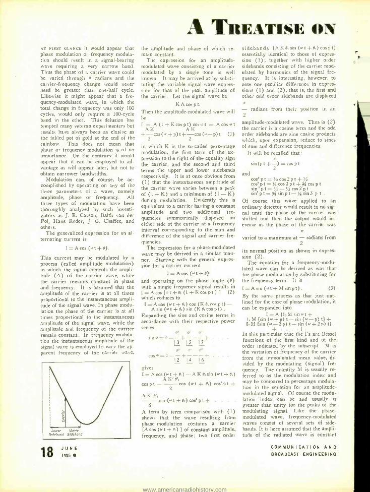
AT FIRST GLANCE it would appear that phase modulation or frequency modula- tion should result in a signal -bearing wave requiring a very narrow band. Thus the phase of a carrier wave could be varied through * radians and the carrier -frequency change would never need be greater than one -half cycle. Likewise it might appear that a fre- quency- modulated wave, in which the total change in frequency was only 100 cycles, would only require a 100 -cycle band in the ether. This delusion has tempted many veteran experimenters but results have always been as elusive as the fabled pot of gold at the end of the rainbow. This does not mean that phase or frequency modulation is of no importance. On the contrary it would appear that it can be employed to ad- vantage as will appear later, but not to obtain narrower bandwidths.
Modulation can, of course, be ac- complished by operating on any of the three parameters of a wave, namely amplitude, phase or frequency. All three types of modulation have been thoroughly analyzed by such investi- gators as J. R. Carson, Balth van der Pol, Hans Roder, J. G. Chaffee, and others.
The generalized expression for an al- ternating current is
I =Acos (wt +9).
This current may be modulated by a process (called amplitude modulation) in which the signal controls the ampli- tude (A) of the carrier wave, while the carrier remains constant in phase and frequency. It is assumed that the amplitude of the carrier is at all times proportional to the instantaneous ampli- tude of the signal wave. In phase modu- lation the phase of the carrier is at all times proportional to the instantaneous amplitude of the signal wave, while the amplitude and frequency of the carrier remain constant. In frequency modula- tion the instantaneous amplitude of the signal wave is employed to vary the ap- parent frequency of the carrier wave,
Lower Upper
Sidebond Sideband
JUNE 1935
A TREATISE ON the amplitude and phase of which re- main constant.
The expression for an amplitude - modulated wave consisting of a carrier modulated by a single tone is well known. It may be arrived at by substi- tuting the variable signal -wave expres- sion for that of the peak amplitude of the carrier. Let the signal wave be
KA cos p t.
Then the amplitude- modulated wave will be I = A (1 + K cos p t) cos w t = Acoswt
AK AK + -cos (w +p)t + -cos (o+ -p)t (1)
2 2
in which K is the so- called percentage modulation, the first term of the ex- pression to the right of the equality sign the carrier, and the second and third terms the upper and lower sidebands respectively. It is at once obvious from (1) that the instantaneous amplitude of the carrier wave varies between a peak of (1 + K) and a minimum of (1 - K) during modulation. Evidently this is equivalent to a carrier having a constant amplitude and two additional fre- quencies symmetrically disposed on either side of the carrier at a frequency interval corresponding to the sum and difference of the signal and carrier fre- quencies.
The expression for a phase -modulated wave may be derived in a similar man- ner. Starting with the general expres- sion for a carrier current
I = A cos (wt +9) and operating on the phase angle (e) with a single frequency signal results in I =Acos [wt +e, (1 +Kcospt) ] (2) which reduces to I=A cos (wt+e,) cos (IC e, cos pt)-
A sin (w t + e,) sin (K e, cos pt) .
Expanding the sine and cosine terms in accordance with their respective power series
os Sin m=T--+----I-
I 3 15 I7
ms
cos h= l --- + - --+ 2 14. 16
gives I= A cos (wt +6,)- AK8, sin (wt +e,)
AK'e', rns p t cos (w t + 9,) cos' p t +
2
\ K' e', sin (w t O,) cos' pt+
6
A term by term comparison with (1) shows that the wave resulting from phase modulation contains a carrier [A cos (w t + e,) ] of constant amplitude, frequency, and phase; two first order
sidebands [A Ke,sin (wt +e,) cospt] essentially identical to those of expres- sion (1) ; together with higher order sidebands consisting of the carrier mod- ulated by harmonics of the signal fre- quency. It is interesting, however, to note one peculiar difference in expres- sions (1) and (2), that is, the first and other odd order sidebands are displaced x
radians 2
amplitude -modulated wave. Thus is (2) the carrier is a cosine term and the odd order sidebands are sine cosine products which, upon expansion, reduce to sines of sum and difference frequencies.
It will be recalled that: A
sin(pt + -) =cospt 2
and cos' pt= % cos2pt+ cos'pt='/gcos3pt+)a cos pt sin' pt= '' /z -' /z cos2pt sin' pt= 34 sin pt -% sin 3 p t .
Of course this wave applied to an ordinary detector would result in no sig- nal until the phase of the carrier was shifted and then the output would in- crease as the phase of the carrier was
,r
varied to a maximum at - radians from 2
its normal position as shown in expres- sion (2).
The equation for a frequency -modu- lated wave can be derived as was that for phase modulation by substituting for the frequency term. It is
I =Asin (wt +Msinpt). (3)
By the same process as that just out- lined for the case of phase modulation, it can be expanded into
I = A [I.M sin wt+ I, M {sin (w + p) t - sin (w - p) t} + I,M {sin (w -2p) t -sin (w +2p) t}
In this particular case the I's are Bessel functions of the first kind and of the order indicated by the subscript. M is the variation of frequency of the carrier from the unmodulated mean value, di- vided by the modulating (signal) fre- quency. The quantity M is usually re- ferred to as the modulation index and may be compared to percentage modula- tion in the equation for an amplitude - modulated signal. Of course the modu- lation index can be and usually is greater than unity for the peaks of the modulating signal. Like the phase - modulated wave, frequency -modulated waves consist of several sets of side - bands. It is here assumed that the ampli- tude of the radiated wave is constant
from their position in an
COMMUNICATION AND BROADCAST ENGINEERING
www.americanradiohistory.com
FREQUENCY MODULATION and that its frequency is varied in ac- cordance with the instantaneous ampli- tude of the modulating or signal fre- quency. If the modulation index is less than unity, then the amplitude of the first set of sidebands will be approxi- mately proportional to this index, while the amplitude of the higher order side - bands will be negligible. When the modulation index exceeds unity the higher order sidebands become of more importance, in that they carry more energy, while the carrier amplitude drops rapidly. Under this condition there will be sideband components of ap- preciable magnitude extending on either side of the carrier up to the extreme lim- its between which the carrier frequency is varied. As the modulation index be- comes greater, less and less energy is carried by the carrier and first set of sidebands (i.e., those nearest the carrier in frequency) and more and more by the higher order sidebands.
From the above discussion, it is ap- parent that the bandwidth transmitted with a frequency -modulated signal is at least of the same order as that of ali amplitude- modulated signal and may be much greater. This fact coupled with the difficulty of receiving such sig- nals has largely prevented the use of frequency modulation in the past. It is evident that before detection the fre- quency- modulated signal must be re- converted to an amplitude -modulated signal. In general this is done by the use of an equalizer network in which the attenuation is directly proportional to frequency. In the simplest case the side of the resonance curve of a tuned circuit might be used. That is, the cir- cuit is cletuned so that the carrier falls to one side of the band instead of in the center. This is shown in the accompany- ing illustration, from which it is evi- dent that the pass band of the tuned circuit is not used for signal transmis- sion. If this is to be done without dis- tortion, it is obvious that some additional equalization may be required. More- over the amplitude of the side band com- ponents depends upon the signal fre- quency so that the modulation index is inversely proportional to the signal or modulating frequency. Thus, if the amplitude of the modulation frequency is kept constant while the frequency is varied, the modulation index and hence the amplitude of the intelligence- bearing sidebands will decrease as the signal fre- quency is increased. This may of course introduce distortion. At any rate it is evident that frequency modulation is most readily applicable at a single wave- length rather than over wide bands.
JUNE 1935
It] the foregoing an attempt has been made to show something of the differ- ences involved between frequency and amplitude modulation as well as some of the difficulties involved in the use of the former. It is obvious that frequency and phase modulation involve an almost completely new technique and that some of our conceptions of modulation as well as some of the customary axioms must be changed or discarded. This does not of course mean that frequency modula- tion has no place in the present scheme of things. On the other hand it appears that it offers numerous advantages at very short wavelengths and may come into general use when the proper equip - ment for its transmission and reception is available. All of which brings us to that time- tested axiom of communication which may be stated' : The total amount of information which may be transmitted over a system which is limited to a re- stricted frequency range is proportional to the product of the frequency range which it transmits by the time which it is available for transmission.
Recently Major E. H. Armstrong has suggested that inasmuch as the elimina- tion of frequency modulation at ultra - short wavelengths is very difficult to accomplish, it might be better to employ it exclusively, instead of amplitude mod- ulation. As a matter of fact frequency modulation is generally admitted to be easier of accomplishment at waveengths in the centimeter range than amplitude modulation. In addition, Major Arm- strong has worked out ways and means of accomplishing this and has announced that experiments conducted between the Empire State Building in New York City and other stations in New Jersey and Long Island have proven that the theoretical advantages of such a system may be realized in practice.
It is present practice in radio systems to use as narrow a bandwidth as pos- sible, consistent with the degree of fi-
delity required, to reduce interference both from static and from thermal and tube noises to the lowest possible value it the receiver output. It has been shown that the noise due to thermal agitation and shot effect has a constant distribu- tion with frequency. That is, a given bandwidth at any frequency admits a given amount of noise. This is, of course. not true of static which disap- pears at very high frequencies.
According to Major Armstrong. thermal noise and shot effect consists of variations not only in amplitude but also
1. Transmission of Information -R. V. L. Hartley -Reis Sv.tem Technical Journal. Vol.
VII. pg. 535.563. July. 1928.
in frequency, so that they would ap- pear in the output of a receiver intended for reception of frequency -modulated signals as well as those intended for the reception of amplitude -modulated sig- nals. However, he finds that by employ- ing a greater swirl; in the frequency of the carrier than that caused by the above mentioned disturbances the signal -to- noise ratio can be greatly improved. It would seem that this might be carried to almost any desired degree with the penalty, of course, of a wider trans- mitted frequency band. It should be borne in mind that when the carrier swing exceeds the frequency band of the. modulating signal (i.e., the modulation index is greater than unity) that the higher order sidebands begin to assume importance. This, of course, calls for a wider received band, but since it over - rides set noise this is of no consequence at frequencies at which there is no static.
While it is not the intention to set forth here the details of the circuits which Major Armstrong has invented and proposed for use at ultra -short wavelengths the reader is referred to patent No. 1,941,069 which describes transmitting and receiving circuits cap- able of producing the results claimed by Major Armstrong. In general the cir- cuits described in this patent consist of a more or less conventional transmitter in which frequency modulation is ob- tained in a novel and somewhat involved manner. Current limiting is provided to insure that the transmitter transmits a current of constant amplitude. Thus a frequency -modulated signal of constant amplitude results. The receiver is of the triple- detection type and feeds a balanced output or bridge circuit. Two series tuned circuits each feeding a rectifier are, in turn, connected differentially between receiver output and the headphones. One tuned circuit resonates at the lower edge of the second i -f band while the other similar tuned circuit resonates at the upper edge of the second i -f band. The circuits are so arranged that equal outputs of noise are produced by the two last detectors, the outputs of which are differentially connected, thus eliminating to a large extent set noises. This is ac- complished by arranging the tuned cir- cuits so that their impedances over the audible range-on either side of the sec- ond intermediate frequency is equal. Noise currents are therefore balanced out, whereas signal currents which vary over a much wider frequency range are unbalanced. One edge of one resonance curve is used for signals of increasing amplitude and the other side is used for decreasing the amplitude.
COMMUNICATION AND BROADCAST ENGINEERING
www.americanradiohistory.com

Tenth Annual I. R. E. Convention HOTEL STATLER- 11ETROIT -JULY 1 -2 -3
THE TENTH ANNUAL CONVENTION of the Institute of Radio Engineers will be held at the Hotel Statler in Detroit on the first, second and third of July. The following is the complete program:
SUNDAY, JUNE 30
Registration: 4 :00 P.M.-6 :00 P.M.
MONDAY, JULY I
9:00 A.M.: Registration and opening of exhibitions. Official welcome and technical session.
Addresses of welcome by Stuart Ballantine, President of the Institute, and H. L. Byer - lay, Chairman of the Convention Com- mittee.
Technical Session, Large Meeting Room: Electron Beams and Their Application
in Low- Voltage Devices, by H. C. Thomp- son, RCA Radiotron Division, RCA Manu- facturing Company, Harrison, N. J.
Frequency Control by Low Power Fac- tor Line Circuits, by C. \V. Hansel', F. I I. Kroger and P. S. Carter, RCA Com- munications, New York, N. Y.
Design and Equipment of a 50- Kilowatt Broadcast Station for WOR, by J. R. Poppele, Station WOR, Newark, N. J., and F. W. Cunningham and A. \V. Kish - paugh, Bell Telephone Laboratories, New York, N. Y.
10:00 A.M.-11:00 A.M.: Official greetings at ladies' headquarters.
11:00 A.M.-S:00 P.M.: Trip No. 1. Ladies' sight- seeing trip.
12:30 P.M.-2:00 P.M.: Luncheon and inspection of exhibits.
2:00 P.M.-3:30 P.M.: Technical Session, Large Meeting Room:
Automatic Selectivity Control, by G. L. Beers, RCA Victor Division, RCA Manu- facturing Company, Camden, N. J.
Automatic Frequency Control by Charles Travis, RCA License Laboratory, New York, N. Y.
Radio -Panel Lamps and Their Charac- teristics, by J. H. Kurlander, Westinr.- house Lamp Company, Bloomfield, N. J.
2:00 P.M. -3:30 P.M.:
Technical Session, Small Meeting Room:
Magnetron Oscillators for Generating Frequencies from 300 to 600 Megacycles, by G. R. Kilgore, RCA Radiotron Di- vision, RCA Manufacturing Company, Harrison, N. J.
An Unattended Ultra -Short -Wave Radio -Telephone System, by N. E. Schlaack and F. A. Polkinghorn, Bell Telephone Laboratories, New York, N. Y.
Some Notes on Piezoelectric Crystals, by Isaac Koga, Tokyo University of En- gineering, Tokyo, Japan.
3:30 P.M :6:00 P.M.: Trip No. 1 General Motors Research
Laboratory.
6:00 P.M. -7:00 P. M.: Inspection of exhibits.
TUESDAY, JULY 2
9:00 A.M.: Registration and opening of exhibition.
0:00 A.M.-1 I :30 A.M.: Technical Session, Large Meeting Room:
Recent Developments of Class B Audio - and Radio- Frequency Amplifiers, by L. E. Barton, RCA Victor Division, RCA Manu- facturing Company, Camden, N. J.
General Theory and Application of Dy- namic Coupling and Power -Tube Design, by C. F. Stromeyer, Revelation Patents Holding Company, New York, N. Y.
Notes on Intermediate- Frequency Trans- former Design, by F. W. Scheer, S. W. Sickles Coil Company, Springfield, Mass.
10:00 A.M.-11:30 A.M.: Technical Session, Small Meeting Room:
Some Theoretical Considerations Relat- ing to Vacuum-Tube Design, by G. D. O'Neill, Hygrade Sylvania Corporation, Salem, Mass.
Ratings and Operating Information on Large High-Vacuum 7 ubes, by R. W. Larson, General Electric Company, Sche- nectady, N. Y., and E. E. Spitzer, RCA Radiotron Division, RCA Manufacturing Company, Harrison, N. J.
Analysis of the Operation of Vacuum Tubes as Class C Amplifiers by I. E. Mouromtseff and H. N. Kozanwski, West- inghouse Electric and Manufacturing Corn- pany, East Pittsburgh, Pa.
10:00 A.M.-11:30 A.M.: Trip No. 3. Ladies' shopping tour.
1 1:30 A.M.-6:00 P. M.: Trip No. 4. Greenfield Village.
6:00 P.M.: Exhibits Close.
7:00 P.M.: Annual banquet and entertainment, Main
Banquet Room.
WEDNESDAY, JULY 3
9:00 A.M.: Registration and opening of exhibition.
10:00 A.M.-11:30 A.M.: Technical Session, Large Meeting Room
A New Tube for Use in Superheterodyne Frequency -Conversion Systems, by C. F. Nesslage, E. W. Harold, and W. A. Harris, RCA Radiotron Division, RCA Manufacturing Company, Harrison, N. J.
A New Type of Gas -Filled Amplifier Tube, by J. D. LeVan and P. T. Weeks, Raytheon Production Corporation, Newton, Mass.
10:00 A.M.-11:30 A.M.: Technical Session, Small Meeting Room:
Ultra -Short -Wave Propagation Over Land, by C. R. Burrows, Alfred Decino and L. E. Hunt, Bell Telephone Labora- tories, New York, N. Y.
.A Note on the Source of Interstellar Interference, by K. G. Jansky, Bell Tele- phone Laboratories, New York, N. Y.
Comparison of Cosmic Data toith Char- acteristics of the Ionosphere at Washing- ton, by E. B. Judson, National Bureau of Standards, Washington, D. C.
A Study of Radio Field Intensity Versus Distance Characteristics of a High Ver- tical Radiator at 1,080 Kilocycles, by S. S. Kirby. National Bureau of Standards, Washington, D. C.
I I:00 A.M.-6:00 P.M.: Trip No. 5. Ladies' luncheon and sight-
seeing trip. I I:30 A.M.-1:00 P. M.:
Luncheon and inspection of exhibits. I:00 P.M.-6:00 P.M.:
Trip No. 6. Ford Motor Plant. 4:00 P. M.:
Closing of exhibits.
COMMERCIAL RADIO BROAD- CASTING IN CHINA
CUT- THROAT competition has become a serious detriment to the legitimate de- velopment of commercial broadcasting in China. Four years ago, when com- mercial broadcasts had gained an as- sured foothold on Chinese programs, the formation of two associations was ad- vocated. One group would represent the radio dealers and the other those in- terested in the various phases of broad- casting. These two groups would con- trol prices, have standard contracts and work in conjunction for a common good.
20 JUNE 1935
Owing to lack of cooperation this plan was never placed in effect. The business today still lacks necessary organization and is faced with competitive methods which retard its legitimate expansion as a commercial asset. (Electrical For- eign Trail,' A- Nt.'s.)
FUTURE OF ENGLISH BROAD - CASTI NG
THE POSTMASTER GENERAL has an- nounced that a committee has been set up to consider the future of broadcast- ing in England after the expiration of the present charter. The committee's
terms of reference are : "To consider the constitution, control and finance of the broadcasting service in this country, and report and advise generally on the conditions under which this service, in- eluding broadcasting to the Empire, tele- vision broadcasting, and the system of wireless exchanges, should be conducted after Dec. 31, 1936." The committee will he presided over by Lord Ullswater, and among its members are Major J. T.
Astor, Mr. C. R. Atlee, and Lady Read - ing.-(Conseulor of Embassy Ray Atherton, April 22. 1035.)
COMMUNICATION AND BROADCAST ENGINEERING
www.americanradiohistory.com

m-w
Ilì!
111 °Ì ix s W móóó
() ¢ x (f) `"x: > - ;% °1 'I 0 :<3 wx W a "` =°_' " r m°;
(J7 I- Q $Ñ rYÉgÉ x s' O "1 QWi
w w N z c' i I 1 O ós E.E W él ""' óó'i - f } w v ;Rr,oá;ó°_
_ Y 10 0 O U) Y ' - O I e1 .
44 = Z O .$.§:- A O : -_ ?- 0 J O p.Éá íiL'i
c - 5^
cn U ~ a Z = x_ °
\A 5. il
Z 4 4 xa ': I W W ( t _ _ ="z - - .R
2 4 m z E"r`°`:` :8
- \`a °+û
(i O t7 eoz_Qm: ~ dl 1Q
a - w E`a - >I .. ag a 0 u c``E: ó; - ' a1._
U.1 Z o`LL Y ..
ri . á
< 2 ci G
_ ~ _
á ;
"
m
m w Q o \a H / .3`s2
g=oS-a z R H '
D L. - R A j¡
$
_E
/ »I
¡ ER a I °
: 2 a1 :I =1 1. A7$+
: ° a^
iI
1 I °I ' rl (n 'I" !
=;° -g
9`WOs&I "g
W= ssat,
=1 x 5 ¡_ -
7, = 7, O WI ^ ó1I; -4
=1 ma1
/4 ?1 .;ad
- : í ° =I W=J
. 1
=W p . EI aF.
- ER 1 =1 1 á¡ =1
1 " °s1
e ;1 m"
o 1 u
/, =1
/ y
el áI W
;I °'
ó 9 H b , i; / i è =` H
w 3 H Y 7 I
1 tl
a
" l
I
o c
I 2 :1
i! 1 °
Y
` =Ì I W
10v1 T V -m °1
i1 °1 ;-
^atl-r: óNá= xy ,sE1 zz'i iyc.
I =
" o'
31
'ill
:1 ni
.1
á((
i g
I '
" gI ól _ O( ) W.g Ñ il
=P - _1 I 0 msì ° =1
" ° : ;1
4 oa 1 s 2 fóz¡
r °sìó
^'yg'mz= ó 0=-5
¡$y$
;_+ enÉ _ 3!118 °ló 1£E W Sa Yg` É e C~
I.
FSa°9 cE :sl eé ± É á"oF
E _ - `':;lì `-ia :° á$. _ s: s °J$=
z a:
gy 1 ' ììt@@ á=1 ° pps Q;gs ióX ¢ É ? 1 .a.8 ri' » 8 a°r?$ _ë° z m g 3_1; a8éo x=, .ì ì"o .Yg: 3£+. -'É -a ó YYöà
;'it;
w I I A I ! ;£»$S °p`: » c Ñ1 c=E" iSé1
1
I Y I A "x 8° `Bá. » I I I: 'x8'1 W Igs'g ; " I
N s 04-01)7 -°4` 2Wr ú- á:$° 3!afi
WS:; $" : zÉF; K5 ys`ú Ç1Bñ
` S
m
ii`-zf WW`.s3 ás_iE
`
°x°-W `§E ?Xi _ u=$a óglEE s.:ä sI=__.5 z?E'la
1 I
I.; + + + I
JUNE 1935
COMMUNICATION AND A BROADCAST ENGINEERING L
www.americanradiohistory.com

TELECOMMUNICATION PANORAMA OF PROGRESS IN THE FIELDS OF COMMUNICATION AND BROADCASTING
FIVE -METER CONTACT BETWEEN NEW YORK AND PHILADELPHIA
'1 HE GARDEN CITY RADIO CLUB has again scored in the ultra -high - frequency field. During a regular contact between station W2DLG, located at the Hotel New Yorker, and station W2AMJ, owned and operated by Frank Lester of Bergenfield, N. J., the voice from the hotel was picked up by W3AZG at Riverton, N. J., which is just across the river from Philadelphia. The total air distance is approximately 100 miles.
Mr. Arthur H. Lynch, who was oper- ating the New Yorker station at the time, says that the news from Philadel- phia is 'most encouraging, particularly in view of the fact that the transmitter at the New York end was operating on comparatively low power, the input to the oscillator circuit being but 28 watts.
COMMUNICATION WITH LITTLE AMERICA
THE SECOND Byrd Antarctic Expedition yielded data for twenty -two sciences, Rear Admiral Richard E. Byrd re- vealed in the course of his brief remarks at a private luncheon given in his honor by Thomas J. Watson, president of International Business Machines Cor- poration, at the Waldorf Astoria Hotel.
These sciences included that of com- munication, to which an important con- tribution was made by the Expedition in cooperating in the sending of an experimental message eleven thousand miles by radiotype from its camp in Little America to the temporary Inter- national Business Machines experi- mental laboratory erected at Ridgewood, N. J. Despite bad conditions in the ether, a single word "WATSON" was transmitted to prove the experiment a success.
The experimental message trans- mitted from Little America to Ridge- wood was sent just before the Byrd Antarctic Expedition broke camp. The Byrd party had an experimental set of radiotype sending equipment. consist- ing of an all- electric typewriter manu- factured by International Business Ma- chines Corporation, with apparatus for emitting a radio impulse for each key struck.
In the transmission of the message, the impulses were sent out by radiotype from Little America and were received over the circuits of the Mackay Radio
22 JUNE 1935
ULTRA -SHORT -WAVE BEAM ANTENNA DESIGNED AND INSTALLED BY A R T H U R
LYNCH. ON THE 48TH FLOOR OF THE HOTEL NEW YORKER. THE TWO TELESCOPIC HALF- WAVE RADIATORS A R E
SHOWN IN FOREGROUND AND THE REFLECTORS IN
BACKGROUND.
& Telegraph Co.. at a special inter- ceptor station in the woods outside of the Ridgewood. N. J.. laboratory, where it had been found necessary to place the receivers and amplifiers in order to avoid interference from the ignition systems of passing automobiles. At the intercepting station the received im- pulses were reduced to microwave - length, amplified and transmitted through a special portable microwave installation to the IBM laboratory at Ridgewood, where they were received on a special experimental radiotype receiving installation.
The tests were in charge of Walter S. Lemmon, general manager of the Radiotype Division of International Business Machines Corporation, who developed the apparatus, assisted by two well known radio engineers of the division, D. E. Replogle and C. T. Fitch.
CZECHOSLOVAK PUBLIC UTILITY PROPOSAL
A PROPOSAL submitted recently to the Czechoslovak Ministry of Posts and Telegraphs for consideration suggests that Czechoslovak public utility com- panies pay a certain percentage of their profits to a special fund from which disbursements would be made to ex-
pand propaganda for the use of radio sets in Czechoslovakia.
According to estimates of the "Radio - mournal" broadcasting company, the total value of electricity consumed annually by socket -type radio sets amounts to at least 75 million crowns ($3.000,000) and therefore it is claimed that the public utility companies, which profit from radio operation, should carry at least a portion of the expense of advertising undertaken to promote sales of radios.
It is doubtful that the proposal will be accepted as a number of local power companies are extending special rate reductions on electric current consumed by radio sets and such concerns claim that in this manner they are doing their just share for the development of radio listening in Czechoslovakia. (Electrical Foreign Trade .Ynfes.)
WIBM SETS RECORD AT 7:30 A. M., April 11, WIBM began a continuous twenty-four hour broadcast grind for the purpose of establishing a world's record for endurance, and to make an engineering analysis of the technical equipment of the station under the strain of continuous load.
For over twenty days- 473 -% hours
COMMUNICATION AND BROADCAST ENGINEERING
e
www.americanradiohistory.com

to be exact -a continuous program was
arranged. Not for one second during
this entire period was the carrier broken.
The sign -off at 1:00 a. m., May 1, was
made necessary by the fact that the 1370
channel frequency -measurement period
began at that time. It was, therefore,
only because of a regular established or-
der of the. Commission that it became
necessary to silence the WIBM carrier.
At sign -off time everything was func-
tioning perfectly and, undoubtedly, many
more hours could have been rolled up
before a mechanical failure occurred.
Letters from DX listeners in thirty -
seven states were received. during this
broadcast, and Manager Charles A.
llill said that the whole stunt was a
huge success . . . from several angles.
First, the technical equipment of
WI BM has been proven to be dependa-
bly designed, and while the transmitter is of composite construction, it is a com-
plete high -fidelity layout. Constant use
of the cathode -ray oscilloscope for
maintenance of these quality standards
during the test gave the station engi-
neers much valuable data.
SUN ECLIPSE IMPROVES SHORT-
WAVE TRANSMISSION CONFIRMING TIHEORETICAI. RESEARCH of
the effect of a sun eclipse on short -wave
radio, the 12 ground radio stations of
Eastern Air Lines and pilots of six
passenger -(nail- express Douglas airlin-
ers of the company in the air at the
time reported that transmission and
reception efficiency as well as distance
was improved approximately 50 percent
at the peak of the partial sun eclipse
Sunday, February 3.
Working with research engineers of
the Bell Telephone Laboratories, de-
signers of short -wave equipment used
by Eastern Air Lines, Capt. E. V. Rick -
enbacker, general manager, ordered all
ground stations and planes in the air to keep a careful check of conditions during the eclipse, which lasted from 10:29 a.m. to 12:33 p.m (EST).
"Conditions improved slowly until about 11:15 p.m.," reported Ricken-
backer. "Then between 11:25 a.nt. and
11:31 a.m., when the peak of the eclipse arrived, pilots and ground radio opera- tors said that almost ideal conditions existed, being identical to twilight op-
eration. Static noise was almost com- pletely eliminated and signals 400 and 600 stiles away boomed in over the re-
TO KEEP AUDIENCE AND PERFORMERS COOL AND COMFORTABLE IN THE NEW STUDIOS OF RADIO STATION WIOD. MIAMI. THIS YORK AIR -
CONDITIONING EQUIPMENT HAS BEEN IN- STALLED. IT CONSISTS OF TWO YORK C1000 COILS AS SHOWN. WITH ACCESSORY FANS AND
CONTROL APPARATUS.
JUNE 1935
ceivers sufficiently to require volume control."
While Eastern Air Lines personnel were reporting the phenomena, research engineers of Bell Telephone Labora- tories, J. P. Schafer and William M.
Goodall, made observations and con- ducted ground tests which coincided with the work of the airline.
"There was a decrease of as much as 25 to 30 percent in ionization in the lower levels of the so- called Kennelly - Heaviside layer," reported J. C. Schel- leng, radio research engineer of the Bell Telephone Laboratories. "The ex- cellent signal strength, improved trans- mission and reception of radio mes- sages between ground stations and planes was undoubtedly clue to the de- creased absorption of radio waves in the layer about 60 to 70 miles above the earth.
"Normally during the daytime these lower layers, as for example the 'E' region of the Kennelly- Heaviside layer, hangs like a curtain below the layer from which radio waves are re- flected back to earth. This weakens the signals before they reach the reflecting layer. Though the density of the ioni- zation of the 'F' region, about 150 miles up, was probably also reduced, never- theless it remained easily dense enough to reflect the waves. Consequently the eclipse reduced absorption but not re- flection."
Full reports as noted at the time by the radio operators of Eastern Air Lines have been turned over to Western Elec- tric and Bell Telephone Laboratories' engineers by Captain Rickenbacker.
RADIO TO REPLACE TELEGRAPH IN PHILIPPINES
THE SECRETARY Of Public Works and Communications is preparing a bill to
be introduced into the next session of
the Legislature in July to appropriate money for the installation of a new radio -telegraph service to replace the present telegraph service throughout the Philippine Islands. It is not certain just how large an appropriation will be required, but it will probably be between P250,000 and P500,000. The plan con- templates the establishment of radio stations at the principal centers through- out the Islands, including stations at Brooks Point, Palawan, and Sitangki. Jolo, to combat smuggling of aliens. New transmitting and receiving sets would be purchased. The Secretary of
Public Works and Communications is convinced that the radio service could he operated more economically than the telegraph service and that it would also be more reliable. being less vulnerable to typhoons.
This plan for installation of a beano
radio service has no connection with the proposed plan, which it is believed will ultimately be realized, for installing a Government -owned broadcasting sys- tem for purposes of propaganda and in-
struction o:, alternatively, taking over the broadcasting stations already in
operation. (Trade Commissioner J. Bartlett Richards. Manila, Electrical Foreign Trade .Votes.)
GUIDING SHIPS BY RADIO
SATISFACTORY tests have been made at Havre, France, for guiding vess -ls en- tering and leaving ports by radio.:'.ar- bor pilots would therefore be replaced by signalling posts, which would guide the ships up to the berth assigned them when entering the harbor. Excellent results have also been obtained from similar tests at Marseilles and Alger. - (Assistant Trade Commissioner Les - trade Brown, Paris, May 10. 1935.)
COMMUNICATION AND BROADCAST ENGINEERING L3
www.americanradiohistory.com

FEDERAL COMMUNICATIONS COMMISSION REPORTS
GARDNER APPOINTED COUNSEL FOR TELEPHONE INVESTIGATION O. MAX I:ARDNER, former Governor of North Carolina, was named, on April 29, Counsel for the telephone investigation by the Fed- eral Communications Commission at a meeting presided over by Dr. Irvin Stew- art, Vice -Chairman, in the absence, on ac- count of illness, of Chairman Anning S. Prall. This investigation was authorized by Public Resolution No. 8, 74th Congress, approved March 15, 1935.
Mr. Gardner is an outstanding lawyer with a wide grasp of public questions.
He was born March 22, 1882, at Shelby, N. C., and received his early training at North Carolina State College of Agricul- ture and Engineering at Raleigh, and at the University of North Carolina. Soon after his admission to the bar he rose rapidly as a lawyer and for years he has been identified with important litigation.
Mr. Gardner took an active part in the Spanish- American War, serving as team- ster of the First N. C. Infantry. From 1907 to 1914 he was Captain of Company G, First N. C. Infantry.
His term as Governor covered the period from 1929 to 1933.
He is a member of the American and North Carolina Bar Associations, and trus- tee of the State College, Raleigh.
EMERY APPOINTED SECRETARY TO CHAIRMAN WALKER \1R. %% ALTER It EMERY of Norman, Okla- homa, Director of Forensics at the Univer- sity of Oklahoma since 1929, has secured a leave of absence for the summer from his duties at the University of Oklahoma, to assume the duties of Secretary to Com- missioner Paul A. Walker, Chairman of the Telephone Division. He will take over the work of Mr. John J. Hassler, who was recently appointed as Executive Assistant to the Assistant Engineer in charge of Telephones.
Mr. Emery was born at Howe, Okla- homa, in 1907. He is a graduate of the Shawnee, Oklahoma, High School ; of the Oklahoma Baptist University, A. B., 1929; of the School of Law of the University of Oklahoma, L.L.B., 1934; and has done graduate work in government and political science. He has also completed a number of courses in law and economics dealing with public utilities. He has been a mem- ber of the Oklahoma State Bar since 1933.
Upon graduation from the Oklahoma Baptist University, he was employed as field representative for that school until he became Director of Debating at the University of Oklahoma, in the fall of 1929. Mr. Emery has been an outstanding student. He won a number of state and regional contests in debate and oratory and is a member of honor, scholastic and debating organizations. He is co- author of a manual of debate and parliamentary prac- tice which is now used as a text in the University of Oklahoma.
Mr. Emery's duties at the University of Oklahoma have included the direction of Radio Station WNAD at the University.
ENGINEERS FOR TELEPHONE INVESTIGATION THE COMMISSION announces that the follow- ing engineers, heretofore appointed for the telephone investigation, have reported for duty.
24 JUNE 1935
Manfred K. Toeppen From Lansing, Michigan. Graduate of
Washington University, St. Louis, Mis- souri. At present Chief Consulting Engi- neer, Michigan Public Utilities Commis- sion. He has held this position on several occasions and in the interim has been in private practice in connection with matters before the Michigan Public Utilities Com- mission and other commissions. He has been recently engaged in handling the in- vestigation of the Michigan Bell Tele- phone Company which is before the Public Utilities Commission. George S. Macomber
From New York City. Graduated from Cornell University in 1900. Graduate work at Cornell, Johns Hopkins and Columbia. Served in various engineering capacities with municipalities, Interstate Commerce Commission and comes to the Federal Com- munications Commission from the New York State Public Service Commission. William H. Schlasman
From Reading, Pennsylvania. Gradu- ated from Lehigh University, M.E., 1920, from Yale, M.S. in E.E., 1926. Engineer Long Lines Department, A. T. & T., Vita - phone Corporation, Electrical Research Products, Inc., and consulting engineer. Harold G. Tufty
From Evanston, Illinois. Graduated from University of Wisconsin. Engineer with various manufacturing and utility companies. Barry T. Benson
From Sherman, Texas. Presbyterian Memorial College, Leonard, Texas. Served in various engineering capacities with a number of telephone and telegraph com- panies for the past twenty years, includ- ing various independent telephone com- panies and both the Western Union and Postal Telegraph Companies. George B. Donohue
From Milwaukee, Wisconsin. Graduated from Marquette University. Served in various engineering capacities with West- ern Electric Company for the past eleven years, and has been engaged in indepen- dent consulting work.
WHITTINGTON RECEIVES APPOINTMENT 771E FEDERAL COMMUNICATIONS COMMIS- SION. on May 11, announced the appoint- ment of William Vallie Whittington as Secretary to Commissioner Irvin Stewart. Mr. Whittington was born near Benton, Illinois, December 10, 1904. He has been for several years a legal assistant in the Department of State. A brief statement of his scholastic training and of his career fol lows :
Elementary school, eight years, Benton, Illinois; Benton Township High School, four years; Georgetown University and Law School, five years, Washington, D. C.; LL.B. Degree, 1928; French Language School, three years, Washington, D. C.
Assistant in office of County Recorder and Clerk of Circuit Court, Benton, Illi- nois, 1922 -23; Secretary in Law Office, Benton, Illinois, 1923 ; clerical and adminis- trative employment in the Department of State, 1924 -30; reporting and special writ- ing for daily newspapers, 1926 -27; admit- ted to Bar of District of Columbia, 1928; admitted to Bar of Illinois, 1928; general
legal practice, 1928 -30; Technical -Legal Assistant, professional and scientific serv- ice, Treaty Division of the Department of State, 1930 -35; research and drafting in relation to treaties, laws and regulations, and assistant since 1931 in work relating to international telecommunication prob- lems; American Delegate to the third meet- ing of the International Radio Consulting Committee (C.C.I.R.) at Lisbon, Septem- ber- October, 1934.
COMMISSION EMPLOYMENT RULING THE FEDERAL. COMMUNICATIONS COMMIS- SION en banc, on May 1, adopted the fol- lowing rule :
No one serving in the Federal Communi- cations Commission on or after July 1, 1935, shall be permitted to practice, appear, or act as an attorney or agent in any case, claim, contest or other proceeding before the Commission or before any division or agency thereof. until two years shall have elapsed after the separation of the said pc-- son from the said service.
CONFERENCE ON TARIFF RULES ON APRIL 3, 1935, the Federal Communica- tions Commission adopted a proposed set of tariff rules, known as Tariff Circular No. 1, and directed that copies thereof be sent to communication carriers required to file schedules of their charges under the Com- munications Act of 1934, with an invitation to the carriers to file written criticisms and suggestions respecting the proposed rules by May I, 1935.
On or before May 1, responses were re- ceived from certain carriers and certain state commissions either approving the pro- posed rules or making certain criticisms and suggestions, and a request was made for an informal conference between repre- sentatives of the carriers and state com- missions and representatives of this Com- mission. at which conference the rules could be discussed and considered.
The matter being under consideration by this Commission on May 8, the Commission set June 6, 1935, at 10 o'clock a. m., as the date and hour when an informal conference between representatives of the carriers. representatives of state commissions and representatives of this Commission was to be held for the purpose of considering the proposed rules. The conference was to be held in the office of the Federal Communi- cations Commission at Washington, D. C.
REVISION OF UNIFORM SYSTEM OF ACCOUNTS FOR TELEPHONE COMPANIES THE FEDERAL COMMUNICATIONS COMMIS- SION on May I, 1935, adopted certain re- visions of the Uniform System of Accounts for Telephone Companies, to become ef- fective January I, 1936.
These revised rules have been the sub- ject of conferences between representatives of the telephone companies and representa- tives of the Federal regulating commis- sions for some years. Public hearing was held thereon before the Federal Communi- cations Commission on November 16, 1934.
One of the most important changes in the system of accounts deals with the ascer- tainment of original cost of properties. The changes have been repeatedly considered and discussed. from time to time, in confer- ences and hearings among representatives of the commissions, both Federal and State, and of the telephone companies.
COMMUNICATION AND BROADCAST ENGINEERING
www.americanradiohistory.com

The publication of the revised uniform system of accounts for telephone companies on May 1 gives the commissions and the utilities an additional two months' time for consideration and for preparation for ef- fectiveness January 1, 1936. It also gives opportunity for hearings before State com- missions with corresponding jurisdiction over intrastate accounts, in time for six months' publication, prior to effectiveness, of any revisions.
The joint conference on May 16 with State Commissions having corresponding jurisdiction over intrastate accounts and the telephone companies, was in response to repeated requests of the telephone com- panies for such conference.
The Federal Communications Commis- sion has carefully considered the record heretofore made, both before the Interstate Commerce Commission and the Communi- cations Commission.
The Commission fully realizes the impor- tance, both to the public and to the utili- ties, of an adequate uniform system of ac- counts, and desires that this uniform system be as free from defects as possible, to avoid the frequent issue of supplementary orders of modification. For these reasons, and to comply with the request of the telephone carriers, the Commission arranged the May 16 conference.
MODIFICATION OF RULE 28
THE COMMISSION on May 21 modified Rule 28 to read as follows :
Rule 28. Insofar as practicable. call sig- nals of radio stations will be designated in alphabetical order from groups available for assignment, depending upon the class of station to be licensed. Because of the large number of amateur stations, calls will be assigned thereto in regular order and requests for particular calls will not be con- sidered except on formal application. The Commission may reassign calls to the last holders of record.
APPLICATIONS GRANTED FOR NEW STATIONS
Telegraph Division
1prit 23, 1935.
CITY OF MUSKOGEE, Oklahoma, granteo construction permit for police sta- tion. 2450 kc, 50 watts. CITY OF LANCASTER, Ohio, granted construction permit to authorize construc- tion of police station. 2430 kc, 50 watts. CITY OF SAVANNAH, Georgia, granted construction permit for police station in emergency service, 30,100, 33,100, 37,100, 40,100 kc, 25 watts. CITY OF TYLER. Texas, granted con- struction permit, 278 kc, 15 watts. April 30, 1935. GEORGE BIEDERMANN, NC -9657, granted aviation- aircraft license, 3105 kc, 20 watts. ALASKA SOUTHERN PACKING COMPANY, La Merced (moored in vicin- ity of False Pass). granted construction permit, fixed public point -to -point tele- graph public coastal -coastal telegraph: (a) 500 kc calling, 460 kc working; (b) 274, 262 kc. The power is 200 watts. To com- municate with ships on frequencies (a), station \VZE. Kamakansk, with frequen- cy 274 kc, and other point -to -point stations in vicinity on 262 kc. ICY STRAITS SALMON COMPANY. Alaska, granted construction permit, fixed public point -to -point telegraph public coast- al- coastal telegraph service. (a) 500 call-
JUNE 1935
ing and 426 working, (b) 246 and 262 kc; 200 watts; points of communication: With ships on frequencies (a), and with point -to- point telegraph stations in vicinity on fre- quencies (b). APEX FISH COMPANY, Port Wake- field, Alaska, granted construction permit, fixed public point -to -point telegraph public coastal- coastal harbor service, 2632 kc, 10 watts, to communicate with WZA, Kodiak, and other point -to -point stations in vicinity and with ships in Alaskan waters. CITY OF DALLAS, Texas, Police De- partment, granted construction permit, mo- bile, general experimental, 30,100, 33,100, 37,100, 40,100 kc, 8 watts. CITY OF LOS ANGELES, California, granted license to cover construction per- mit, police service, portable, 1712 kc, 200 watts, to be used in case of emergency in and around Los Angeles. CITY OF YAKIMA, Washington, granted construction permit, 2414 kc, 50 watts, emis- mision A3, transmitter capable of 100 watts output. .1/ay 7, 1935. CITY OF SAGINAW, Michigan, granted construction permits (10 applications), portable -mobile, general experimental, to operate as a police station in emergency service, 30,100 kc, 10 watts. CITY OF PITTSBURGH, California, granted construction permit (4 applica- tions), portable -mobile, general experimen- tal, 30,100, 33,100, 37,100, 40,100 kc, 5 watts; similar permit granted with the ex- ception of 15 watts power. CITY OF SANTA ROSA, California, granted construction permit, general experi- mental, 30,100, 33,100, 37,100, 40,100 kc, 10 watts ; also granted construction permit (2 applications), mobile, general experi- mental. same frequencies, 2.5 watts. TEXACO DEVELOPMENT CORP., Southwestern U. S., granted construction permit (6 applications), portable, geophysi- cal, 1602, 1628, 1652, 1676, 1700 kc, 7.5 watts. CITY OF LODI, California,.granted con- struction permit, emergency -municipal pol- ice, 2414 kc, 50 watts. TOWN OF SAN ANSELMO, California, Department of Police, granted construction permit, general experimental service, 3.0,100 33,100, 37,100, 40,100 kc, 5 watts ; also granted construction permit (2 applica- tions) for mobile equipment, 2.5 watts. May 14, 1935. AERONAUTICAL RADIO, Inc., Gal- veston, Texas, granted construction permit, aeronautical, 2912, 5042.5 kc; aeronautical point -to -point 2640 kc; 50 watts. H. G. SLINGSBY, NC -381, granted li- cense, aviation- aircraft, 3105 kc, 7.5 watts. TOWN OF HARRISON, New York, granted construction permit, portable -mo- bile. general experimental 30,100, 33,100, 37.100, 40,100 kc, 9 watts. CITY OF SCRANTON Pennsylvania, Police Department, granted permit, general experimental, 30,100, 33,100, 37,100, 40,100 kc, 100 watts. Also, 4 applications for mo- bile equipment, 25 watts. CITY ON SAN BUENA VENTURA, California, granted construction permit, general experimental, 30,100, 33,100, 37,- 100, 40,100 kc, 50 watts. Same for 4 ap- plications, portable- mobile, 10 watts. CITY OF MANCHESTER, New Hamp- shire, Police Department, granted construc- tion permit. general experimental, 30,100, 33,100, 37,100, 40,100 kc, 50 watts. Same for 2 applications, mobile, 5 watts. GL.EASON W. KENRICK, Porto Rico,
granted construction permit, portable, gen- eral experimental, 1614, 2398, 3492.5, 4797.5, 6425, 8655, 12,862.5, 17,310 kc, 1500 watts. Also granted license covering same for period ending October 1, 1936.
ST. LOUIS METROPOLITAN POL- ICE DEPT., Missouri, granted construc- tion permit (6 applications), mobile, gen- eral experimental, 33,100 kc, 5 watts. CITY OF TALLAHASSEE, Florida, granted construction permit, general ex- perimental, 30,100, 33,100, 37,100, 40,100 kc, 25 watts. CITY OF MONROVIA, California, Police Department, granted construction permit, general experimental, 30,100, 33,100, 37,100, 40,100 kc, 12 watts. Same for 2 applica- tions for portable- mobile equipment, 4.5 watts.
Broadcast Division
.1 prit 30, 1935. HART AND NELSON, High Point, North Carolina, granted construction per- mit, 1200 kc, 100 watts, daytime. WESTINGHOUSE ELECTRIC AND MFG. CO., Chicopee Falls, Massachusetts, granted construction permit (2 applica- tions), portable- mobile, special experimen- tal, 31,600, 35,600, 38,600, 41,000, 55,500, 60,500, 86,000- 400,000 kc, 50 watts. Also granted license covering this equipment. .1/ay 7, 1935. NATIONAL BROADCASTING COM- PANY, Chicago, Illinois, granted license to operate broadcast pickup station and use equipment authorized under permit granted for visual broadcast station W9XAP, 1606, 2020, 2102, 2760, 2 kw. May 14, 1935. LEROY HALEY, Durango, Colorado, granted construction permit, 1370 kc, 100 watts, unlimited time. May 21, 1935. ISLE OF DREAMS BROADCASTING CO., Miami, Florida, granted construction permit, portable, broadcast pickup, 1606, 2020, 2102, 2760 kc, 50 watts. \VBNS, Inc., Columbus, Ohio, granted construction permit, 2 applications, portable, -mobile, general experimental, 31,- 100, 34,600, 37,600, 40,600 kc, 2 watts. \VCBD, Inc., Waukegan, Illinois, granted construction permit, portable. general ex- perimental, 31,100, 34,600, 37,600, 40,600 kc. 5 watts.
Telephone and Telegraph Division
.flay 21, 1935. WESTERN RADIO TELEGRAPH CO.. Inc., Bartlesville, Oklahoma, granted con- struction permit, 4805, 4530 kc, 500 watts, specified hours, to communicate with Ca- hokia, Illinois, in the fixed public service. WESTERN RADIO TELEGRAPH CO.. Inc., Oklahoma City, Oklahoma, granted construction permit, fixed public service, 4805. 4530 kc. 500 watts, specified hours, to communicate with Cahokia, Illinois. \VESTERN RADIO TELEGRAPH CO., Inc., Cahokia, Illinois. granted construc- tion permits, 2 stations, fixed public service, 2252 kc unlimited time, 3047.5 and 3022.5 kc day only, 50 watts, to communicate with Cahokia. Illinois. WESTERN RADIO TELEGRAPH CO., Inc., Cahokia, Illinois. granted construc- tion permit. fixed public service. 4805, 4530 kc, specified hours, to communicate with Borger and Breckenridge. Texas. Okla- homa City and Bartlesville. Oklahoma, portable units and all other stations of W. R. T. C. network. Crane. Texas.
COMMUN I CATION AND BROADCAST ENGINEERIN L
www.americanradiohistory.com

VO A
VETERAN WIRELESS OPERATORS
ASSOCIATION NEWS
W. J. McGonagle, Secretary, 112 Willoughby Avenue, Brooklyn, N. Y.
MEMORIAL DAY SERVICES
TnE VETERAN WIRELESS OPERATORS ASSOCIA-
TION held Memorial Services at 5 :45 p.m. on May 30, 1935, at the Wireless Opera- tors Monument in Battery Park. A tablet bearing the name of Ernest E. Dailey, late Chief Radioman of the ill -fated dirigible Macon, which has just been placed on the monument, was unveiled by his widow, Mrs. Dailey, who journeyed from Washington for the Services.
A fifteen- minute broadcast over a WEAF- N BC network marked the Services, dur- ing which George Clark, President of our Association, dramatized the events lead- ing up to the Macon disaster. Commander J. L. Kenworthy, Assistant Chief of the Bu- reau of Aeronautics, U. S. N., flew from Washington to participate in the broadcast. Commander Kenworthy, who was Execu- tive Officer of the Macon on its last voy- age, eulogized Radioman Dailey in the most glowing terms, telling the radio audience of the ambitions of Dailey to become an officer in the Naval service and of his courage and tenacity of purpose in remaining in the radio room to direct rescue vessels which was highly instrumental in effecting the rescue of all but himself and one other member of the dirigible's crew. A firing squad. furnished through the courtesy of the Commandant of the Third Naval Dis- trict, fired three volleys while a Color Guard from the Brooklyn Navy Yard stood at attention and three Naval planes flew overhead dipping each time they passed over the monument. A medal awarded by the Association was presented to Mrs. Dailey by the Secretary. The Services were concluded by the playing of "Taps" by a Naval bugler.
We take this opportunity of publicly ex- pressing our appreciation of the splendid cooperation rendered the Association in making possible the beautiful and impres- sive Memorial Services by the U. S. Navy; Admiral J. K. Taussig, Acting Chief of Naval Operations ; Admiral Yates Sterling, Commandant of the Third Naval District ;
Lieut. Commander J. L. Kenworthy for his part in the program ; the Navy personnel who flew the planes and comprised the Colar Guard and Firing Squad and the Navy bugler; and to the National Broad-
casting Company and Pathe News for bringing these Services to a vast audience throughout the world.
George Clark, our President, deserves the highest praise for arranging the continuity of the broadcast and attending to many of the details. A. F. Wallis was of invaluable assistance in working out the details of the Services.
NEW MEMBERS
E. D. Bryant, residing in Bloomington, Ind., and who operated commercially way hack in 1910, joins the Association as a Veteran Member and automatically becomes a member of the twenty -five year group.
Adam Kalkowsky, of Pan American .Airways down Florida way, joins as a
JUNE 1935
Veteran Member, his service dating back to 1923. He resides in that very romantically titled town of Cocoanut Grove, Florida. .
Don E. Self, formerly connected with the Tropical Radio and Telegraph Company, now with American Airlines, Inc., at Mur- freesboro, Tenn., becomes a Veteran Mem- ber of the Association. He began in coln- mercial radio in 1925.. . . Chester B. Harman, who, judging from his list of as- signments, seems to have been continuously employed in commercial radio since he started in 1927, has been elected to Asso- ciate Membership.
We extend a cordial welcome to our re- cently elected members and invite their co- operation and suggestions in acquainting other eligibles with the work of the Asso- ciation. OLDTIMER
The letter starts off : "Have been hear- ing about the V. W. O. A. and am wonder- ing if I am qualified for membership.
"Some time ago, so long I've forgotten the exact date -about 1903 -I was employ- ed by the Reading Railway as a telegraph operator and heard about wireless on ships and made up my mind that was my job. Left the Reading and visited wireless head- quarters at 42 Broadway and after a wait of three days was assigned to the S. S. Concho of the Mallory Line, call VC, as operator.
Maginnis was operator at Key West Fred Chambers at GV, Galveston; Miller and Wheeler at AX, Atlantic City. Think Payne was one of the boys at New York at that time. Later left, after the DeForest Wireless Company had become the Ameri- can DeForest and then the United Wire- less, and went to the United Fruit on the Cartago, UC, New Orleans to Colon. Was on her only a few trips when she ran aground on Utilla Island off the coast of Honduras, when I sent my first and only CQD through much static to New Orleans, HB, I believe, and got the Heredia and Parisrnina to take off our passajeros. Left her to go with the United."
Our correspondent continues his remin- iscences, recalling some of the names of his contemporaries in the early 1900's. "Dur- ing the early days in New York, when H. J. Hughes was in charge, there was Duffy, and CCG and Mr. Wilson and Dr. De Forest. While I was at Galille, Pickerell and McLarney were at the Waldorf, WA; Dave Heilig at BS Philadelphia; Ben Beckerman was on the Old Dominion and there was Arthur Cohen and Wallace. and the one -armed boy named Edwards, I think: also Don White and R. H. Marriott. Old DF at Manhattan Beach was going strong then.
"Carborundum detectors, electrolytic de- tectors with Wollaston wire ; then Perikon detectors. a Wireless Specialty product at 365.00. Type D tuners with sliders on top and sides, Carborundum defector and po- tentiometer on top, and in 1910, at SN, re- ceived the first loose coupler tuner. Big open -core transformers, 18 Leyd -n jars
with chains inside which were continually burning and corroding off. Helix on top of condenser rack, with spark gap inside. Anchor gaps in the antenna leads. Beauti- ful blue glow around tops of jars and noise of battle when you closed the key."
We thank our correspondent, who is H. R. Baum, of Miami, Florida, for his notes of the days back in the early part of the present century.
PERSONALS Peter Podell postcards that he is now as-
sociated with University Chevrolet, Inc., at 1605 Jerome Avenue, in the Bronx, N. Y.
George Street recently started for Honolulu to assume the managership of an RCA Communications office in Hawaii. Bon voyage and best of luck, George.... Wil- liam S. Gill, first President and originator of our Association name was recently in New York after spending seven years in Holly- wood managing various movie stars enroute on a honeymoon to the west coast of South America. He plans to transfer at the Canal when north bound and proceed up the .Pa- cific Coast to San Pedro. Glad to see you again WSG and we hope you do not re- main away seven years this trip.... The last time we saw Ben Titow he was pre- paring to move to Baltimore to assume charge of the new RCA Communications office in that city. We are certain Ben will relish the Maryland hospitality. He prom- ises to work for the formation of a Balti- more Chapter when he becomes settled there.
Karl Baarslag attended our last spag- hetti party and autographed copies of his book, "S O S To The Rescue," for the members present. . . Glad to see Charles Maps at that meeting, too. Don't forget the beer party, CM. (That is, we hope he didn't forget it, for by the time this reaches print the party will have been held.) Eddie Kaminsky and Charles Carney, both of Radiomarine, were at the last meeting... .
Thomas D. Entz, who has been a member for some time, attended his first meeting. Hope you don't continue to be such a stranger, TDE. . . . V. H. C. Eberlin, our former Treasurer, continues his sojourn under Florida skies. We up north don't envy him naw, though, for we are having our share of warm weather. All of which makes the writing of this material the more laborious. . Mcllvain Ross is now Radio Officer abroad the S. S. Algonquin of the Socony Vacuum Company fleet... .
Charles Kolster is Chairman; Guy R. Ent- wistle, Vice-Chairman ; R. F. Trop, Treas- urer, and Harry Chetham, Secretary of our Boston Chapter. We're always glad to re- ceive those cheery notes from HC follow- ing each meeting of the Boston group. .
K. Anthony continues aboard the U. S. S. Chicago as Radio Electrician, now station- ed on the West Coast. . Lloyd C. Nunn makes his remittance for the current year. . . G. G. Greene is now stationed out at Amagansett, Long Island. Says he would like to get in to the meetings, but distance does not permit. A welcome awaits you GGG when you can make it. . J. Christianson, too, is stationed out East on Long Island at the Port Jefferson station of the A. T. & T. Company, to be exact. Now that the nice weather is with us we may journey out that way some one of these week -ends. . Bill Simon and R. H. Pheysey of the Tropical Company were in attendance and seemed to enjoy our last spaghetti festival. . F. M. Daggett sends in his dues. Have you done so? . . .
An interesting letter from Miles A. New- ton from Florida City, Florida. . . . Mel- vin P. Beckvold inquires about the 1935 Year Books. Yes. we have some on hand and we'll be pleased to send a complete set to members for 50 cents to cover mailing.
COMMUNICATION AND BROADCAST ENGINEERING
h
www.americanradiohistory.com
N
OVER THE TAPE
NEWS OF THE RADIO, TELEGR APH AND TELEPHONE INDUSTRIES
EDMUND BRUCE RECEIVES EDWARD LONGSTRETH MEDAL
Public commendation for the develop- ment of a new radio antenna which greatly improves transoceanic telephone communi- cation was given Mr. Edmund Bruce of Bell Telephone Laboratories May 15 when he received the Longstreth medal of the Franklin Institute, Philadelphia, at its an- nual medal day meeting. This medal, which is awarded each year for the encourage- ment of invention and in recognition of meritorious work in science and the indus- trial arts, was presented to Mr. Bruce for his development of a steerable antenna for use in short -wave radio communication.
This improvement greatly reduces the disturbances called fading, which some- times occur during transoceanic and ship - to -shore radio -telephone conversations. Such disturbances are due to interference between waves which come over different paths from the transmitter. Mr. Bruce found that by using an adjustable antenna in the form of a diamond several hundred feet on a side, it is possible to select one of the strong wave -trains of the arriving signal. discard the others, and thus obtain a clear message.
RCA MOVES NEW YORK OFFICE The New York Office of the Victor Di-
vision, RCA Manufacturing Company, has been moved from 153 East 24th Street, New York City, to Room 1813, RKO Building, 1270 Sixth Avenue, New York City. Mr. T. A. Smith is the District Manager.
NEW TUBE COMPANY The United Electronics Company, 42
Spring Street, Newark, N. J., is a new organization that intends manufacturing radio -transmitting tubes, industrial control and power tubes. According to a state- ment made by this new company, its per- sonnel is made up of "key men of the original De Forest group which built up the Sylvania transmitting -tube line. Our designer is the man who laid out all of this construction. Our head chemical engineer was chief chemist for Sylvania electronics division and co- inventor of the graphite anode processing method. Our production superintendent was factory engineer and assistant production superintendent at Syl- vania. Our chief engineer was the head electrical engineer in this work."
This company is said to be headed in a financial and general management way by men of substantial experience. Their plant is equipped with advanced facilities and tubes of first production are expected to embody certain changes in design.
NEW GENERAL ELECTRIC PUBLICATION As a companion book to GEA -1731,
"How to Make Cable Joints," issued last year, the General Electric Company now has available a new publication, GEA- 1839. "Cable Accessories." The two books should be of interest and assistance to everyone who is engaged in work that in-
JUNE 1935
volves the jointing and terminating of in- sulated cable.
"How to Make Cable Joints" gives clear and concise instructions for splicing, joint- ing, and terminating all types of insulated cable. Its forty -four pages are illustrated with drawings and construction men can easily follow the instructions while on the job.
"Cable Accessories" lists and describes all the materials required for this work -joints, connectors, terminals, reservoirs, and other materials. It has eighty pages and is complete in every respect -including prices. It should prove useful in making up jointing standards and as a general reference book.
Copies of these publications can be ob- tained from the nearest General Electric sales office or from General Electric Com- pany. Dept. 6N -201, Schenectady, N. Y.
AMERICAN INSTRUMENT CATALOG A catalog of Aminco instruments for
radio engineers and broadcasting stations is announced by the American Instrument Company, 774 Girard St., N. W., Wash- ington, D. C.
Instruments described include constant - temperature apparatus, crystals and holders, relays, audio- and radio -frequency indicat- ing instruments, and other Aminco device which are used in radio stations.
WESTINGHOUSE ELECTS NEW DIRECTOR
A. W. Robertson, Chairman of the Board of the Westinghouse Electric and Manufacturing Company, announced, at the Annual Meeting of Stockholders of the Company, held April 10, that Winthrop W. Aldrich, H. B. Rust and Samuel M. Vauclain were reelected members of the Board of Directors.
The election of John L. Hall, Senior Member of the law firm, Choate, Hall & Stewart of Boston, as a Director of the Company, was also announced.
RADIART PERSONNEL CHANGE The Radiart Corporation, Cleveland.
Ohio, announce that Mr. James Dalgleish terminated his employment with them on April 15. Mr. Dalgleish's place has been filled by Mr. Charles S. Blank, formerly associated with the Ohio Varnish Com- pany.
ROSEN APPOINTED RCA JOBBER Raymond Rosen and Company, promi-
nent Philadelphia radio and refrigeration wholesale organization, has been appointed a distributor for the sale of RCA Victor centralized radio, public address. sound reenforcement and other commercial sound systems in the eastern Pennsylvania and southern New Jersey territory. according to an announcement by W. L. Rothen- berger, in charge of those activities for the RCA Manufacturing Company. This pio- neer radio distributing company already
represents RCA Victor in the sale of "magic brain" radio and radio- phonograph instruments.
As a preliminary step in developing the potentialities of the rapidly growing com- mercial sound applications field, the Ray- mond Rosen Company has taken over the business of the L. P. Clark Company of Philadelphia, which has for many years specialized in this work and incorporated it into a newly- created Special Products Division. Paul Ziesmer has been placed at the head of the new department in charge of sales and service, and L. P. Clark will work with him as Sales Engineer.
DUBILIER TOURS EUROPE
William Dubilier, Vice -President in Charge of Research of the Cornell -Dubilier Corporation, of New York, left during the early part of April for a two -month tour of Europe. He will visit the firm's British and continental affiliates, make first -hand observations of engineering progress in several countries and pay particular atten- tion to television developments in Great Britain and Germany.
RCA RADIOTRON APPOINTMENTS
C. R. King, Sales Manager for RCA Radio Tubes, announced the appointment of Paul J. Pfohl, as Sales Manager of the Chicago District, including Illinois, Wisconsin, Indiana and Kentucky, with headquarters at the RCA Radiotron Divi- sion Sales Offices at 520 N. Michigan Avenue, Chicago. Richard A. Graver, formerly Chicago District Sales Manager for RCA Radio Tubes, has been appointed Sales Manager of the Chicago Talking Machine Company, RCA Victor and RCA Radiotron wholesale distributors.
Mr. Pfohl has been identified with RCA Radiotron activities for many years, as factory representative for initial tube- equipment sales to radio manufacturers in the Chicago area, and more recently as wholesale and retail trade representative in the same territory.
Mr. Graver has been with RCA Radio - Iron since 1930 when it was formed as a Company. He was appointed Atlanta Dis- trict Sales Manager, and later Sales Manager of the important Chicago Dis- trict.
TAYLOR APPOINTED SALES MANAGER OF KENYON
The Kenyon Transformer Company, In- corporated, 840 Barry Street. New York City, New York, recently announced the appointment of Mr. William E. Taylor to the position of General Sales Manager.
Mr. Taylor will apply his experience to the promotion of the company's complete line of transformers.
COMMUNICATION AND BROADCAST ENGINEERING L
www.americanradiohistory.com
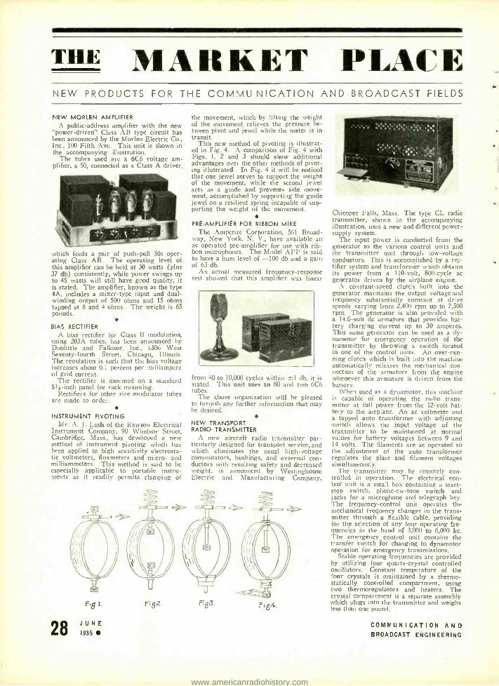
THE MARKET PLACE NEW PRODUCTS FOR THE COMMU NICATION AND BROADCAST FIELDS
NEW MORLEN AMPLIFIER A public- address amplifier with the new
"power -driven" Class AB type circuit has been announced by the Morlen Electric Co., Inc., 100 Fifth Ave. This unit is shown in the accompanying illustration.
The tubes used are a 6C6 voltage am- plifier. a 50, connected as a Class A driver,
which feeds a pair of push -pull 50s oper- ating Class AB. The operating level of this amplifier can be held at 30 watts (plus 37 db) consistently, while power swings up to 45 watts will still have good quality, it is stated. The amplifier, known as the type 4A, includes a mixer -type input and dual - winding output of 500 ohms and 15 ohms tapped at 8 and 4 ohms. The weight is 65 pounds. - BIAS RECTIFIER
A bias rectifier for Class B modulation, using 203A tubes, has been announced by Doolittle and Falknor, Inc., 1306 West Seventy- fourth Street, Chicago, Illinois. The regulation is such that the bias voltage increases about 0.1 percent per milliampere of grid current.
The rectifier is mounted on a standard 5% -inch panel for rack mounting.
Rectifiers for other size modulator tubes are made to order.
INSTRUMENT PIVOTING Mr. A. J. Lush of the Rawson Electrical
Instrument Company, 90 Windsor Street, Cambridge, Mass., has developed a new method of instrument pivoting which has been applied to high sensitivity electrosta- tic voltmeters, fluxmeters and micro- and milliammeters. This method is said to be especially applicable to portable instru- ments as it readily permits clamping of
the movement, which l y lifting the weight of the movement relieves the pressure be- tween pivot and jewel while the meter is in transit.
This new method of pivoting is illustrat- ed in Fig. 4. A comparison of Fig. 4 with Figs. 1, 2 and 3 should show additional advantages over the other methods of pivot- ing illustrated. In Fig. 4 it will be noticed that one jewel serves to support the weight of the movement, while the second jewel acts as a guide and prevents side move- ment, accomplished by supporting the guide jewel on a resilient spring incapable of sup- porting the weight of the movement.
PRE -AMPLIFIER FOR RIBBON MIKE
The Amperite Corporation, 561 Broad- way, New York, N. V., have available an ac operated pre- amplifier for use with rib- bon microphones. The Model APP is said to have a hum level of -100 db and a gain of 63 db.
An actual measured frequency- response test showed that this amplifier was linear
from 40 to 10,000 cycles within ±1 db, it is stated. This unit uses an 80 and two 6C6 tubes.
The above organization will be pleased to furnish any further information that may he desired.
NEW TRANSPORT RADIO TRANSMUTER
A new aircraft radio transmitter par- ticularly designed for transport service, and which eliminates the usual high -voltage commutators, bushings, and external con- ductors with resulting safety and decreased weight, is announced by Westinghouse Electric and :lfanufacturing Company,
Fig]. Fi g2. F183. Fi 8.4.
Chicopee Falls, Mass. The type CL radio transmitter, shown in the accompanying illustration, uses a new and different power - supply system.
The input power is conducted from the generator to the various control units and the transmitter unit through low- voltage conductors. This is accomplished by a rec- tifier system and transformer which obtains its power from a 110 -volt, 800 -cycle ac generator driven by the airplane engine.
A constant -speed clutch built into the generator maintains the output voltage and frequency substantially constant at drive speeds varying from 2,400 rpm up to 7,500 rpm. The generator is also provided with a 14.6 -volt dc armature that provides bat- tery charging current up to 30 amperes. This same generator can be used as a dy- namotor for emergency operation of the transmitter by throwing a switch located in one of the control units. An over -run- ning clutch which is built into the machine automatically releases the mechanical con- nection of the armature from the engine whenever this armature is driven from the battery.
\Vhen used as a dynamotor, this machine is capable of operating the radio trans- mitter at full power from the 12 -volt bat- tery to the airplane. An ac voltmeter and a tapped auto transformer with adjusting switch allows the input voltage of the transmitter to be maintained at normal values for battery voltages between 9 and 14 volts. The filaments are ac operated so the adjustment of the auto transformer regulates the plate and filament voltages simultaneously.
The transmitter may be remotely con- trolled in operation. The electrical con- trol unit is a small box containing a start - stop switch, phohe -cw -tone switch and jacks for a microphone and telegraph key. The frequency -control unit operates the mechanical frequency changer in the trans- mitter through a flexible cable, providing for the selection of any four operating fre- quencies in the band of 3,000 to 6,000 kc. The emergency control unit contains the transfer switch for changing to dynamotor operation for emergency transmissions.
Stable operating frequencies are provided by utilizing four quartz- crystal controlled oscillators. Constant temperature of the four crystals is maintained by a thermo- statically controlled compartment, using two thermoregulators and heaters. The crystal compartment is a separate assembly which plugs into the transmitter and weighs less than one pound.
28 JUNE COMMUNICATION AND 1935 BROADCAST ENGINEERING
a
www.americanradiohistory.com

NEW AIRCRAFT TRANSMITTER
A new aircraft transmitter has been an- nounced by Lear Developments, Inc., 125
W. 17th Street, New York, N. Y. Two views of this unit, the L -35, are shown in the accompanying illustration.
This transmitter has been designed to use 3105 kc as the calling frequency and 3120 kc as the working frequency. The
power output is 35 watts. Voice or car may be used.
The transmitter cabinet measures 8 x 9
x 10 inches and is finished in baked black crackle. The total weight of the transmit- ter, including power supply and remote - control cable, is 40 pounds.
With a 4<i-wave trailing wire antenna the L -35 is said to have a range of 500 miles. A new feature is the automatic reeling in and out of this antenna.
"PERMA -SET"
A new small ceramic base trimmer just brought out is designed to eliminate drift- ing, as constructional features which might cause drifting are said to have been elimi- nated. A distinctive feature is that under the pressure of average settings, the top plate has anchorage at both front and rear. The new trimmer is called the "Perma-
Set," and is supplied in maximum capaci- ties of 30 mmfd to 180 mmfd.
Solar Manufacturing Corporation, 599- 601 Broadway, New York City, are the manufacturers. They also produce wet and dry electrolytics, paper, mica, and trimmer condensers.
KILOVOLTMETER MULTIPLIERS The Shallcross Kilovoltmeter Multipliers
(resistance boxes) have been designed to furnish a practical and inexpensive exter- nal meter multiplier for a wide variety of standard instruments for measuring poten- tials up to 25,000 volts ac or dc.
Potentials of this magnitude are encoun- tered in broadcasting- station transmitters,
JUNE 1935
intermediate- voltage power transmission, electric railways, neon signs, dust precipi- tators, internal combustion engine ignition systems, X -rays, electron tube development and manufacturing, miscellaneous chemical plants, educational institutions and research laboratories.
Measurements of transient voltages can he made conveniently by substituting for the associated meter any of the cathode -ray oscillographs now available on the market.
The Shallcross Multipliers are classified according to resistance, voltage and cur- rent. For example, any Westinghouse 0 -1
do milliammeter or similar instrument of any other make can be associated with the Shallcross Type 720 Multiplier for voltage ranges of 1, 2, 5, 10 and 20 kilovolts.
Complete information on these units is contained in Bulletin 700. Address- the Shallcross Manufacturing Company, Col - lingdale, Pennsylvania.
SEMI -AUTOMATIC TRANSMITTER TUNING In changing transmitter tuning from one
wavelength to another it is desirable and necessary to effect the change in the short- est possible time. This is especially true in airway communications where a ground station may be transmitting weather reports on one wavelength, a direction beam on another and talking with pilots aloft on the third. It is also essential that the trans- mitter he returned to identically the same
wavelength each time the same information is again to be broadcast to make it easier tor the pilots to tune their receivers. To accomplish semi- automatic tuning of the transmitter the following equipment is used:
A six -position selector switch, mounted on the control panel, provides for selection of any one of five circuits and an off posi- tion. Selection of any one circuit may be made from any previous position of the switch without closing any other circuit. A relay is used to connect the transmitter for the desired wavelength. It consists of five independently- operated relays mounted side by side, each one having three normally open poles. The contacts short circuit various sections of the tuning coils and are located as close to the coils as possible to reduce capacity effects and prevent induc- tive coupling.
Struthers Dunn, Inc., of Philadelphia, Pa., are in a position to supply this equip- ment.
PUBLIC -ADDRESS AMPLIFIER The Radolek Company announces a new
high- quality all -purpose model medium - power public- address amplifier with a num- ber of unusual features.
This amplifier was designed for the medium -sized installations in which higher power and therefore necessarily more cost- ly amplifiers are not necessary.
This unit allows the use of carbon, and
capacity, dynamic or velocity microphones -operates up to 7 dynamic speakers -pro- vided with complete plug- and -socket -input and output connections- two -input channels with mixing and fading equipment - equipped with tone control and has a flat frequency- characteristic curve from 100 to 7,000 cycles.
Complete descriptive literature is avail- able from the Radolek Co., 611 \V. Ran- dolph St., Chicago.
NEW TRANSMITTING CONDENSERS A new line of porcelain- encased mica
transmitting condensers, designed for ama- teur, police and small broadcast transmit- ters, has been brought out by the Cornell - 1)ubilier Corporation, 4377 Bronx Boule- vard, New York. Designated as the Type 86, the line includes thirteen sizes ranging
from .00005 mfd to .1 mmfd, in voltage rat- ings front 2,000 to 12,500 volts.
COMMUNICATION AND BROADCAST ENGINEERING 29
www.americanradiohistory.com

"FRONT OF PANEL" SOCKET The Gates Radio and Supply Company,
Quincy, Illinois, announce the introduction of an improved type of L design or, better known, "Front of Panel" socket. These are made for standard tubes as well as for 50 -watt type tubes and are of heavy cast
brass with bakelite sockets, or on special order Isolantite sockets may be had.
Finish is in black, baked on to assure a rugged finish that will not chip.
Full details and prices available by writing the above concern.
THE TORK "TYMIT" The Tork Clock Company, Mount Ver-
non, New Turk. have available a timing device to automatically turn on and off electrical appliances, such as, radios, lamps, refrigerators, fans, heaters, etc. This unit is equipped with two pointers which can be set for the time of day you wish some electrical appliance to start operation and the time for which you wish it to be turned off ... and, if desired, left on those settings permanently.
These devices are available in two sizes. The No. 6 Tymit is a 600 -watt plug -in type, for all domestic uses except oil burn- ers. The No. 15 Tymit is a 1500 -watt unit that may be installed for oil burner, sign, window, and indoor commercial uses. They come finished in black and chrome or walnut and chrome. Designed for operation on 115 -volt, 60 -cycle ac.
STA -WARM IRONS The Sta -Warm Electric Co., 508 N.
Chestnut, Ravenna, Ohio, have available their Sta -Warm Irons in four sizes, 3 -inch to 1% -inch. These units have a twistlock connection. And, it is stated. that by rotat- ing the tapered copper tip in its special seat, all scales may be ground out to continually maintain maximum heat transference. Fur- ther data will be supplied oy the above company.
Q -METER
The Boonton Radio Corporation, Boon- ton, N. J., are producing their new Type 100 -A Q- Meter, a modern high -speed laboratory and factory instrument for the measurement of coils, condensers, resistors, and other circuit components. This instru- ment has been developed by engineers of the Radio Frequency Laboratories to fill the need for a completely contained in- strument for measuring over a wide range of radio frequencies (50 kc to 50 mc).
Heretofore the Q of a coil has been de- termined by the assemblage of numerous pieces of equipment, by computations, and by repeated reference to calibration curves. The Q -Meter requires no additional ap- paratus for its operation. It contains a complete r -f oscillator, a measuring circuit consisting of a tuning condenser and the external coil which is being measured, a vacuum -tube voltmeter of special design which reads the voltage developed across the tuning condenser, and a means of in-
troducing a known amount of the oscillator voltage in series in the measuring circuit.
The procedure in measuring Q consists of either adjusting the oscillator to a pre- determined frequency and tuning the cir- cuit under measurement to resonance, or conversely of tuning the circuit with a predetermined capacitance and adjusting the oscillator to resonance. At resonance the voltmeter indicates the Q of the cir- cuit.
The outstanding characteristic of this in- strument are the speed and facility with which measurements may be made due to the direct- reading frequency calibration of the oscillator, the self- contained oscillator coil system, the direct- reading calibration of the tuning condenser and of the Q volt- meter ... and the fact that the cabinet design and location of controls on a slop- ing panel places the calibrated dials and controls directly under and on a plane normal to the line of vision.
There are two Q ranges on the meter, 0 -250 and 0 -500. while the tuning con- denser range is continuously variable from 40 to 450 mmfd. The power supply oper- ates from 100 /120 -volt, 60 -cycle ac, with a power consumption of approximately 50 watts.
The Q -Meter is a more useful instrument than its name implies. It is a universal instrument with which the radio -frequency inductance, capacitance and resistance of coils, condensers, resistors, switches, in- sulating materials, etc., may be determined.
VOLTAGE -REGULATING TRANSFORMER In localities with great fluctuation of
line voltage -much higher or much lower than normal -as is frequent on lighting plants in rapidly growing cities or sub-
urban sections, the highest performance of electric appliances can be maintained more easily, and the life of appliances greatly increased by keeping the voltage supply nearest normal rating.
The Voltage -Regulating Transformer herewith illustrated, manufactured by the General Transformer Corporation, Chi- cago, has a positive, manually- controlled adjustment. A snap selector switch at the front is easily turned to primary tap to deliver proper voltage to the appliance. A sensitive voltmeter. mounted on the trans- former case -dial up (convenient for read- ing), plainly indicates when the unit de- livers rated voltage.
The unit is housed in an attractive wrin- kle finish black steel case. Size, 434" x 7" x 63/4" high. It is provided with four non -scratching (soft) rubber supports.
These Voltage -Regulating units are regu- larly supplied in three models . one for normally 110 -volt 50 -60 cycle which trans- forms 70- 80- 90- 100 -110 -120 or 130 volts to 110 volts at 160 watts.
One for normally 220 -volt 50 -60 cycle
which transforms 100- 115- 130 -145 -160 -175 or 190 volts to 110 volts at 160 watts.
One for normally 220 -volt 50 -60 cycle which transforms 140 -160- 180 -200 -220 -240 or 260 volts to 110 volts at 160 watts.
Other voltages or higher capacities are furnished according to specifications.
MOBILE PUBLIC-ADDRESS SYSTEM
The Operadio Manufacturing Co., St. Charles, Illinois, are introducing their Model 62 Mobile Public- Address System. This unit, which has a power output of 18 watts, is storage -battery operated, all power being obtained from a 6 -volt supply, and has been designed for service in cars. A false bottom which is adjustable to the pitch of the seat permits placing the unit on any seat still maintaining a level turn- table. All the controls are next to the
driver and accessible for instant control. Three power switches are provided to
control the turntable motor, the amplifier filaments, and the amplifier B supply. Sub- stantial current saving is possible through judicious use of these switches. particularly the one controlling the B supply and the speaker fields, it is stated.
The Model 62 is a Class A three -stage system using two 76's and two 2B6's. The overall gain is 75 db. The dimensions are 20 x 15 -3/4 x 10 -3 inches and the shipping weight is 94 pounds. Further information may be obtained by writing for Bulletin 94.
NEW PORTABLE P -A SYSTEM
A new portable public- address and sound -reenforcement system for moderate -
sized public places, compactly self -con- tained in a carrying -case and weighing only 28% pounds has been introduced by the RCA Victor Commercial Sound Sales De- partment.
This unit is suited to the steadily grow- ing market for an inexpensive portable sound system. It has been designed for such applications as window demonstra- tions in dealers' stores, counter -to- kitchen restaurant call systems, and for local fairs and carnivals. The new sound system is to be known as Model PG63 -B and will be made available to radio and electrical supply dealers and service organizations through the regular RCA Victor Distribu- tors . and in some cities through RCA Victor Commercial Sound Distributors as well.
Exceptional tone quality and simplicity of operation are two of the principal features which distinguish this low -cost system, according to Mr. W. L. Rothen- berger, Manager of RCA Victor Com- mercial Sound Sales. The equipment has been designed so that actual operation is as convenient and fool -proof as that of an ordinary radio receiver, he said.
30 JUNE COMMUNICATION AND 1935 BROADCAST ENGINEERING
4
www.americanradiohistory.com

AMERICAN MICROPHONE CO. A California Corporation
Microphones of Quality Condensers, Carbons, Dynamics, and Ribbons
New catalogue available upon request. 1915 South Western Avenue, Los Angeles, Calif.
"THE CRYSTAL SPECIALISTS SINCE 1925"
PIEZO- ELECTRIC CRYSTALS GrARANTEED Accurate to BETTER than .01%
SCIENTIFIC RADIO SERVICE Send for FREE Booklet and /'rice List!
UNIVERSITY PARK - - - - HYATTSVILLE, MD.
BLILEY CRYSTALS Supplied to any frequency from 20 Kcs. to 15,000 Kcs.
For Radio Write for Bulletin C -4
TRANSMITTERS and price list. RECEIVERS MONITORS
STANDARDS t-r BLILEY ELECTRIC CO.
Union Station B ,,ildins, Erie, Pa.
Genuine Sapphire and Diamond Needles for Grooving, Recording, Cutting and -¡ Reproducing on Aluminum, Celluloid and Commercial Discs, blank or pre -grooved.
MEYER for tKOttStH CO.,
circular. ULI Inc.
64 FULTON STREET NEW YORK, N. Y.
Yes! Subscribers may date back their subscriptions to include the first number (October) of Communication and Broadcast Engineering.
A limited number of extra copies have been printed so that files may be kept com- plete.
The subscription rate is S3.00 yearly. Foreign and Canada S4.00 yearly.
Bryan Davis Publishing Co., Inc.
19 East 47th Streei
New York City
JUNE 1935
COMMUNICATION AND A BROADCAST ENGINEERING 3
www.americanradiohistory.com
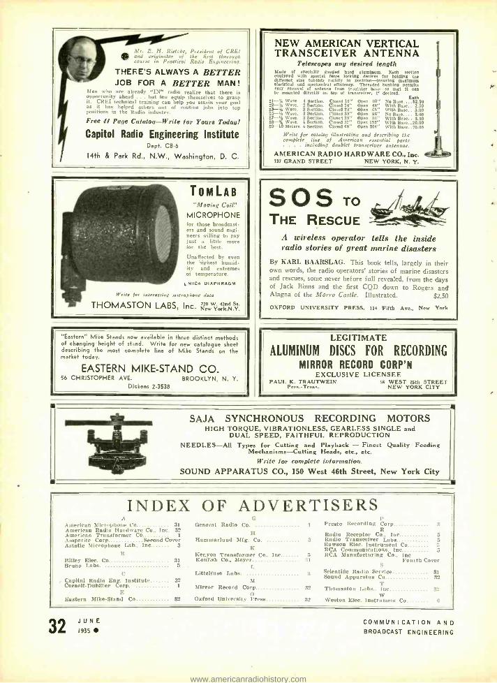
dfr. E. H. Rietzke, President of CREI and originator of the first thorough
rse in Practical Radio Engineering.
THERE'S ALWAYS A BETTER JOB FOR A BETTER MAN!
Men who are already "IN" radio realize that there is opportunity ahead ... but few equip themselves to grasp it. CREI technical training can help you attain your goal as it has helped others out of routine jobs into top positions in the Radin industry.
Free JJ Page Catalog-Write for Yours Today!
Capitol Radio Engineering Institute Dept. CB -6
14th & Park Rd., N.W., Washington, D. C
TOM LAB "Mooing Coil"
MICROPHONE for those broadcast- ers and sound engi- neers willing to pay just a little more for the best.
Unaffected by even the highest humid- ity and extremes of temperature.
MICA DIAPHRAGM
Write for interesting microphone data
THOMASTON LABS, Inc. New ÿork,N Y.
"Eastern" Mike Stands now available in three distinct methods of changing height of stand. Write for new catalogue sheet describing the most complete line of Mike Stands on the market today.
EASTERN MIKE -STAND CO 56 CHRISTOPHER AVE. BROOKLYN, N. Y.
Dickens 2.3536
NEW AMERICAN VERTICAL TRANSCEIVER ANTENNA
Telescopes any desired length Made of specially gauged hard aluminum. Each section equipped with special force locking devices for holding Use different size tubing. rigidly In position -Insuring maximum electrical and mechanical efficiency. Threaded bushing permits easy removal of antenna from insulator base -so that It can be mounted directly on top of transceiver. If desired.
gI -'A Wave. 4 Section. L2-V. Wave. 2 Section. II3 -i4 Wave. 3 Section. 55-1 ware. 3 Section. 27 -'i Nave. 3 Section. La-4. Wave. 4 Section. 69-10 Meters. 4 Section.
Closed 16" Closed 24" Closed 28" Closed 38" Closed 38" Closed 57" Closed 68"
Each Open 60" No Base. ...82.50 Open 48" With hase.. 2.50 Open 65' with Base.. 3.00 Open 96" No Base.... 3.00 Open 96" With Base.. 3.50 Open 152" With llase..20.00 Open 204" With Base..20.00
Write for catalog illustrating and describing the complete line of American essential parts . , . . including doublet transceiver antennae.
AMERICAN RADIO HARDWARE CO., Inc. 137 GRAND STREET NEW YORK, N. Y.
SOS TO
THE RESCUE .1 wireless operator tells the inside radio stories of great marine disasters
By KARL BAARSLAG. This book tells, largely in their ,wn words, the radio operators' stories of marine disasters
and rescues, some never before full revealed, from the days of Jack Binns and the first CQD down to Rogers and Alagna of the Morro Castle. Illustrated. $2.50
OXFORD UNIVERSITY PRESS, 114 Fifth Ave., New York
LEGITIMATE
ALUMINUM DISCS FOR RECORDING
MIRROR RECORD CORP'N EXCLUSIVE LICENSEE
PAUL K. TRAUTWEIN 55 WEST 25th STREET Pres. -Tress. NEW YORK CITY
SAJA SYNCHRONOUS RECORDING MOTORS HIGH TORQUE, VIBRATIONLESS, GEARLESS SINGLE and
DUAL SPEED, FAITHFUL REPRODUCTION NEEDLES -All Types for Cutting and Playback - Finest Quality Feeding
Mechanisms -Cutting Heads, etc., etc.
{Frite for complete infuriation. SOUND APPARATUS CO., 150 West 46th Street, New York City
INDEX OF ADVERTISERS .t
American Microphone t'o 31 American Radio Hardware Co.. Inc. 32 American Transformer Co 1
Amperite Corp Second Cover Astatic Microphone Lab.. Inc 3
B Bliley Elen. Co. Bruno Labs. 5
C , Capital Radio Eng. Institut*. 32
Cornell- Dubiller Corp. 1
ti General Radio Co.
H Hanlmarlund Mtg. Co.
K Kenyon Transformer Co.. Inc
31 Koulish Co., Meyer
E Eastern Mike -Stand Co 32
Littelfuse Labs.
Mirror Record Corp fl
Oxford University l'ress
l'resto Recording Corp 3 R
Radio Receptor Co.. Inc. 5 3 Radio Transceiver Labs 5
Rawson Elec. Instrument t'o RCA Communications. hue. 5
5 RCA Manufacturing Co.. Inc. :15 Fourth Cover
3
S
Scientific Radio Service 31 Sound Apparatus Co 32
T 3' Thomaston Labs.. NI' 3"
W 32 Weston Elen. Instrument Co r,
JUNE 1935
COMMUNICATION AND BROADCAST ENGINEERING
www.americanradiohistory.com

y
e THE Group Subscription Plan for COM-
MUNICATION AND BROADCAST ENGINEERING
enables a group of engineers or department
heads to subscribe at two -thirds the usual yearly
rate.
The regular individual rate is $ 3.00 a year. In
groups of 4 or more, the subscription rate is
$2.00 a year. (In Canada and foreign coun-
tries, $ 3.00.) Each subscriber should print his
name and address clearly and state his occupa-
tion- whether an executive, engineer, depart-
ment head, plant superintendent, or foreman,
etc.
Possibly your associates would be interested in this
group plan
(Communication and Broadcast Engineering)
BRYAN DAVIS PUBLISHING CO., Inc. 19 East 47th Street, New York, N. Y.
www.americanradiohistory.com

RV Makes Another Great Contribution
to Crime Control
No severe drain on car battery. Spe- cial generator is furnished, driven by engine, supplying 250 watts to transmitter. Only one tube is con- nected with the battery and it draws less current than a headlight. Tubes are easily replaced and are standard
types obtainable anywhere.
ET-5022 Mobile Transmitter fits easily inside standard rear trunks. May also be located within car if desired. Self-contained in strong but light aluminum case. mounted on shock absorbers. Total weight about 60 lbs.
Adds 2 -way communication to Terra-Wave Police Radio System
Here is the biggest news since the introduction of the famous RCA Terra -Wave Police Radio! Now your patrol cars can be equipped for 2 -way radio communication, easily doubling the effectiveness of the system. Cars using the new RCA Terra- Wave Mobile Transmitter can call headquarters by radio to transmit important information, ac- knowledge orders, answer questions, ask for help, advise when returning to service. Within 3 seconds after pressing a switch, every word spoken by the driver is heard by the despatcher. There is no in- terruption of work on the immediate emergency.
Several years of intensive research went into this remarkable development. It had to be 100% right before it was worthy to bear the RCA Terra -Wave
name. Power is 25 watts actually put on the air, the highest ever offered for such use. Our tests prove conclusively that this much power must be used if complete reliability is to be had -and nothing less than absolute reliability is good enough for police use.
The transmitter is compact, simple to operate and so sturdy that only a major collision can in- jure it. No changes are required in your present RCA Terra -Wave equipment. The 2 -way feature is obtained merely by installing the new transmitter in each of your cars. Write for complete details and specifications of this second great RCA con- tribution to the speed and efficiency with which your department controls crime.
Sales and Service Representatives in Principal Cities
TERRA -WAVE POLICE RADIO SYSTEM RCA MANUFACTURING COMPANY, INC., CAMDEN, NEW JERSEY
(A Radio Corporation of America Subsidiary)
www.americanradiohistory.com