Embed Size (px)
Citation preview
CAM-M8C u-blox M8 Concurrent GNSS Antenna Module Data Sheet
Highlights:
• Concurrent reception of GPS/QZSS, GLONASS, BeiDou
• Miniature size and weight with low power consumption
• Embedded, omnidirectional and wideband antenna
• Industry leading –164 dBm navigation sensitivity
• Optional external antenna
• Crystal variant to meet cost requirement
www.u-blox.com
UBX-14044858 - R02
CAM-M8C - Data Sheet
UBX-14044858 - R02 Advance Information Page 2 of 26
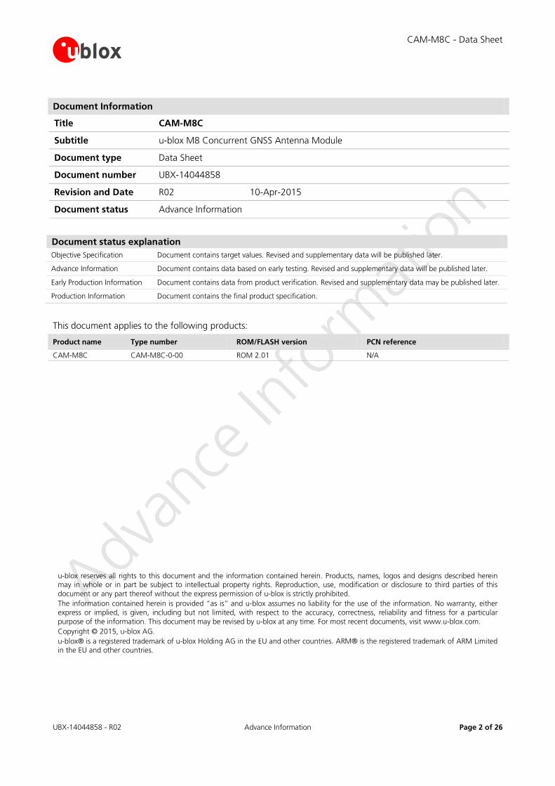
Document Information
Title CAM-M8C
Subtitle u-blox M8 Concurrent GNSS Antenna Module
Document type Data Sheet
Document number UBX-14044858
Revision and Date R02 10-Apr-2015
Document status Advance Information
Document status explanation Objective Specification Document contains target values. Revised and supplementary data will be published later.
Advance Information Document contains data based on early testing. Revised and supplementary data will be published later.
Early Production Information Document contains data from product verification. Revised and supplementary data may be published later.
Production Information Document contains the final product specification.
This document applies to the following products:
Product name Type number ROM/FLASH version PCN reference
CAM-M8C CAM-M8C-0-00 ROM 2.01 N/A
u-blox reserves all rights to this document and the information contained herein. Products, names, logos and designs described herein may in whole or in part be subject to intellectual property rights. Reproduction, use, modification or disclosure to third parties of this document or any part thereof without the express permission of u-blox is strictly prohibited. The information contained herein is provided “as is” and u-blox assumes no liability for the use of the information. No warranty, either express or implied, is given, including but not limited, with respect to the accuracy, correctness, reliability and fitness for a particular purpose of the information. This document may be revised by u-blox at any time. For most recent documents, visit www.u-blox.com. Copyright © 2015, u-blox AG. u-blox® is a registered trademark of u-blox Holding AG in the EU and other countries. ARM® is the registered trademark of ARM Limited in the EU and other countries.
CAM-M8C - Data Sheet
UBX-14044858 - R02 Objective Specification Contents
Page 3 of 26
Contents Contents .............................................................................................................................. 3
1 Functional description .................................................................................................. 5 1.1 Overview .............................................................................................................................................. 5 1.2 Product features ................................................................................................................................... 5 1.3 GNSS performance ............................................................................................................................... 6 1.4 Block diagram ....................................................................................................................................... 7 1.5 GNSS .................................................................................................................................................... 7
1.5.1 GPS ............................................................................................................................................... 7 1.5.2 GLONASS ...................................................................................................................................... 7 1.5.3 BeiDou .......................................................................................................................................... 7 1.5.4 QZSS ............................................................................................................................................. 8
1.6 Assisted GNSS (A-GNSS) ....................................................................................................................... 8 1.6.1 AssistNow™ Online ....................................................................................................................... 8 1.6.2 AssistNow™ Offline ...................................................................................................................... 8 1.6.3 AssistNow™ Autonomous ............................................................................................................. 8
1.7 Augmentation Systems ......................................................................................................................... 9 1.7.1 Satellite-Based Augmentation System (SBAS) ................................................................................. 9 1.7.2 Differential GPS (D-GPS) ................................................................................................................ 9
1.8 Odometer ............................................................................................................................................. 9 1.9 EXTINT: External interrupt ..................................................................................................................... 9
1.9.1 Pin Control .................................................................................................................................... 9 1.9.2 Aiding ........................................................................................................................................... 9
1.10 TIMEPULSE ...................................................................................................................................... 10 1.11 Protocols and interfaces .................................................................................................................. 10 1.12 Interfaces ........................................................................................................................................ 10
1.12.1 UART ........................................................................................................................................... 10 1.12.2 SPI ............................................................................................................................................... 10 1.12.3 Display Data Channel (DDC) ........................................................................................................ 10
1.13 Clock generation ............................................................................................................................ 11 1.13.1 Oscillators .................................................................................................................................... 11 1.13.2 Real-Time Clock (RTC) ................................................................................................................. 11
1.14 Power management ........................................................................................................................ 11 1.14.1 DC/DC converter ......................................................................................................................... 11 1.14.2 Operating modes ........................................................................................................................ 11
1.15 Antenna .......................................................................................................................................... 12 1.15.1 Embedded Antenna .................................................................................................................... 12 1.15.2 External GPS/GLONASS antenna connectivity .............................................................................. 12 1.15.3 Active antenna control (ANTON).................................................................................................. 12 1.15.4 Embedded antenna operation ..................................................................................................... 12

CAM-M8C - Data Sheet
UBX-14044858 - R02 Objective Specification Contents
Page 4 of 26
2 Pin Definition .............................................................................................................. 14 2.1 Pin assignment ................................................................................................................................... 14
3 Configuration management ...................................................................................... 16 3.1 Interface Selection (DSEL) ................................................................................................................... 16
4 Electrical specification ................................................................................................ 17 4.1 Absolute maximum rating .................................................................................................................. 17 4.2 Operating conditions .......................................................................................................................... 18 4.3 Indicative power requirements ............................................................................................................ 18
5 Mechanical specifications .......................................................................................... 19
6 Reliability tests and approvals .................................................................................. 20 6.1 Reliability tests .................................................................................................................................... 20 6.2 Approvals ........................................................................................................................................... 20
7 Product handling & soldering .................................................................................... 21 7.1 Packaging ........................................................................................................................................... 21
7.1.1 Reels ........................................................................................................................................... 21 7.1.2 Tapes .......................................................................................................................................... 21
7.2 Shipment, storage and handling ......................................................................................................... 22 7.2.1 Moisture Sensitivity Levels ........................................................................................................... 22 7.2.2 Reflow soldering ......................................................................................................................... 22 7.2.3 Antenna ageing .......................................................................................................................... 22 7.2.4 ESD handling precautions ............................................................................................................ 22
8 Default messages ....................................................................................................... 23
9 Labeling and ordering information ........................................................................... 24 9.1 Product labeling .................................................................................................................................. 24 9.2 Explanation of codes........................................................................................................................... 24 9.3 Ordering codes ................................................................................................................................... 24
Related documents........................................................................................................... 25
Revision history ................................................................................................................ 25
Contact .............................................................................................................................. 26
CAM-M8C - Data Sheet
UBX-14044858 - R02 Objective Specification Functional description
Page 5 of 26
1 Functional description
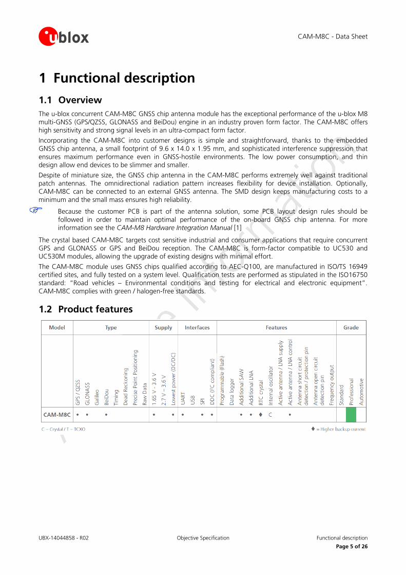
1.1 Overview The u-blox concurrent CAM-M8C GNSS chip antenna module has the exceptional performance of the u-blox M8 multi-GNSS (GPS/QZSS, GLONASS and BeiDou) engine in an industry proven form factor. The CAM-M8C offers high sensitivity and strong signal levels in an ultra-compact form factor.
Incorporating the CAM-M8C into customer designs is simple and straightforward, thanks to the embedded GNSS chip antenna, a small footprint of 9.6 x 14.0 x 1.95 mm, and sophisticated interference suppression that ensures maximum performance even in GNSS-hostile environments. The low power consumption, and thin design allow end devices to be slimmer and smaller.
Despite of miniature size, the GNSS chip antenna in the CAM-M8C performs extremely well against traditional patch antennas. The omnidirectional radiation pattern increases flexibility for device installation. Optionally, CAM-M8C can be connected to an external GNSS antenna. The SMD design keeps manufacturing costs to a minimum and the small mass ensures high reliability.
Because the customer PCB is part of the antenna solution, some PCB layout design rules should be followed in order to maintain optimal performance of the on-board GNSS chip antenna. For more information see the CAM-M8 Hardware Integration Manual [1]
The crystal based CAM-M8C targets cost sensitive industrial and consumer applications that require concurrent GPS and GLONASS or GPS and BeiDou reception. The CAM-M8C is form-factor compatible to UC530 and UC530M modules, allowing the upgrade of existing designs with minimal effort.
The CAM-M8C module uses GNSS chips qualified according to AEC-Q100, are manufactured in ISO/TS 16949 certified sites, and fully tested on a system level. Qualification tests are performed as stipulated in the ISO16750 standard: “Road vehicles – Environmental conditions and testing for electrical and electronic equipment”. CAM-M8C complies with green / halogen-free standards.
1.2 Product features
CAM-M8C - Data Sheet
UBX-14044858 - R02 Objective Specification Functional description
Page 6 of 26
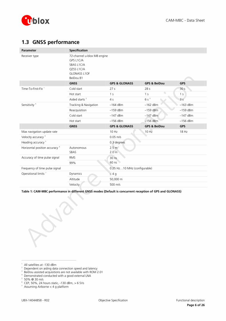
1.3 GNSS performance Parameter Specification
Receiver type 72-channel u-blox M8 engine GPS L1C/A SBAS L1C/A QZSS L1C/A GLONASS L1OF BeiDou B1
GNSS GPS & GLONASS GPS & BeiDou GPS
Time-To-First-Fix 1 Cold start 27 s 28 s 30 s
Hot start 1 s 1 s 1 s
Aided starts 2 4 s 6 s 3 3 s
Sensitivity 4 Tracking & Navigation –164 dBm –162 dBm –163 dBm
Reacquisition –159 dBm –159 dBm –159 dBm
Cold start –147 dBm –147 dBm –147 dBm
Hot start –156 dBm –156 dBm –156 dBm
GNSS GPS & GLONASS GPS & BeiDou GPS
Max navigation update rate 10 Hz 10 Hz 18 Hz
Velocity accuracy 5 0.05 m/s
Heading accuracy 5 0.3 degrees
Horizontal position accuracy 6 Autonomous SBAS
2.5 m 2.0 m
Accuracy of time pulse signal RMS 30 ns 60 ns 99%
Frequency of time pulse signal 0.25 Hz…10 MHz (configurable)
Operational limits 7 Dynamics ≤ 4 g
Altitude 50,000 m
Velocity 500 m/s
Table 1: CAM-M8C performance in different GNSS modes (Default is concurrent reception of GPS and GLONASS)
1 All satellites at -130 dBm 2 Dependent on aiding data connection speed and latency 3 BeiDou assisted acquisitions are not available with ROM 2.01 4 Demonstrated conducted with a good external LNA 5 50% @ 30 m/s 6 CEP, 50%, 24 hours static, -130 dBm, > 6 SVs 7 Assuming Airborne < 4 g platform
CAM-M8C - Data Sheet
UBX-14044858 - R02 Objective Specification Functional description
Page 7 of 26
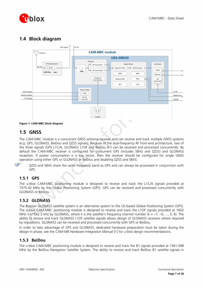
1.4 Block diagram
Figure 1: CAM-M8C block diagram
1.5 GNSS The CAM-M8C module is a concurrent GNSS antenna receiver and can receive and track multiple GNSS systems (e.g. GPS, GLONASS, BeiDou and QZSS signals). Because of the dual-frequency RF front-end architecture, two of the three signals (GPS L1C/A, GLONASS L1OF and BeiDou B1) can be received and processed concurrently. By default the CAM-M8C receiver is configured for concurrent GPS (includes SBAS and QZSS) and GLONASS reception. If power consumption is a key factor, then the receiver should be configured for single GNSS operation using either GPS or GLONASS or BeiDou and disabling QZSS and SBAS.
QZSS and SBAS share the same frequency band as GPS and can always be processed in conjunction with GPS.
1.5.1 GPS The u-blox CAM-M8C positioning module is designed to receive and track the L1C/A signals provided at 1575.42 MHz by the Global Positioning System (GPS). GPS can be received and processed concurrently with GLONASS or BeiDou.
1.5.2 GLONASS The Russian GLONASS satellite system is an alternative system to the US-based Global Positioning System (GPS). The u-blox CAM-M8C positioning module is designed to receive and track the L1OF signals provided at 1602 MHz + k*562.5 kHz by GLONASS, where k is the satellite’s frequency channel number (k = –7, –6, ..., 5, 6). The ability to receive and track GLONASS L1OF satellite signals allows design of GLONASS receivers where required by regulations. GLONASS can be received and processed concurrently with GPS or BeiDou.
In order to take advantage of GPS and GLONASS, dedicated hardware preparation must be taken during the design-in phase, see the CAM-M8 Hardware Integration Manual [1] for u-blox design recommendations.
1.5.3 BeiDou The u-blox CAM-M8C positioning module is designed to receive and track the B1 signals provided at 1561.098 MHz by the BeiDou Navigation Satellite System. The ability to receive and track BeiDou B1 satellite signals in
CAM-M8C - Data Sheet
UBX-14044858 - R02 Objective Specification Functional description
Page 8 of 26
conjunction with GPS results in higher coverage, improved reliability and better accuracy. BeiDou can be received and processed simultaneously with GPS or GLONASS. Global coverage is scheduled for 2020.
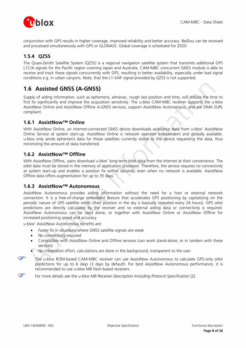
1.5.4 QZSS The Quasi-Zenith Satellite System (QZSS) is a regional navigation satellite system that transmits additional GPS L1C/A signals for the Pacific region covering Japan and Australia. CAM-M8C concurrent GNSS module is able to receive and track these signals concurrently with GPS, resulting in better availability, especially under bad signal conditions e.g. in urban canyons. Note, that the L1-SAIF signal provided by QZSS is not supported.
1.6 Assisted GNSS (A-GNSS) Supply of aiding information, such as ephemeris, almanac, rough last position and time, will reduce the time to first fix significantly and improve the acquisition sensitivity. The u-blox CAM-M8C receiver supports the u-blox AssistNow Online and AssistNow Offline A-GNSS services, support AssistNow Autonomous, and are OMA SUPL compliant.
1.6.1 AssistNow™ Online With AssistNow Online, an internet-connected GNSS device downloads assistance data from u-blox’ AssistNow Online Service at system start-up. AssistNow Online is network operator independent and globally available. u-blox only sends ephemeris data for those satellites currently visible to the device requesting the data, thus minimizing the amount of data transferred.
1.6.2 AssistNow™ Offline With AssistNow Offline, users download u-blox’ long-term orbit data from the Internet at their convenience. The orbit data must be stored in the memory of application processor. Therefore, the service requires no connectivity at system start-up and enables a position fix within seconds, even when no network is available. AssistNow Offline data offers augmentation for up to 35 days.
1.6.3 AssistNow™ Autonomous AssistNow Autonomous provides aiding information without the need for a host or external network connection. It is a free-of-charge embedded feature that accelerates GPS positioning by capitalizing on the periodic nature of GPS satellite orbits (their position in the sky is basically repeated every 24 hours). GPS orbit predictions are directly calculated by the receiver and no external aiding data or connectivity is required. AssistNow Autonomous can be used alone, or together with AssistNow Online or AssistNow Offline for increased positioning speed and accuracy.
u-blox’ AssistNow Autonomous benefits are:
• Faster fix in situations where GNSS satellite signals are weak • No connectivity required • Compatible with AssistNow Online and Offline services (can work stand-alone, or in tandem with these
services) • No integration effort, calculations are done in the background, transparent to the user.
The u-blox ROM-based CAM-M8C receiver can use AssistNow Autonomous to calculate GPS-only orbit predictions for up to 6 days (3 days by default). For best AssistNow Autonomous performance, it is recommended to use u-blox M8 flash-based receivers.
For more details see the u-blox M8 Receiver Description Including Protocol Specification [2]
CAM-M8C - Data Sheet
UBX-14044858 - R02 Objective Specification Functional description
Page 9 of 26
1.7 Augmentation Systems
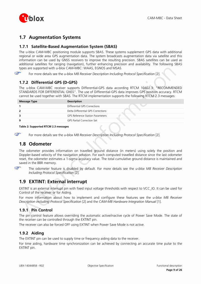
1.7.1 Satellite-Based Augmentation System (SBAS) The u-blox CAM-M8C positioning module supports SBAS. These systems supplement GPS data with additional regional or wide area GPS augmentation data. The system broadcasts augmentation data via satellite and this information can be used by GNSS receivers to improve the resulting precision. SBAS satellites can be used as additional satellites for ranging (navigation), further enhancing precision and availability. The following SBAS types are supported with u-blox CAM-M8C: WAAS, EGNOS and MSAS.
For more details see the u-blox M8 Receiver Description Including Protocol Specification [2].
1.7.2 Differential GPS (D-GPS) The u-blox CAM-M8C receiver supports Differential-GPS data according RTCM 10402.3: "RECOMMENDED STANDARDS FOR DIFFERENTIAL GNSS". The use of Differential-GPS data improves GPS position accuracy. RTCM cannot be used together with SBAS. The RTCM implementation supports the following RTCM 2.3 messages:
Message Type Description
1 Differential GPS Corrections
2 Delta Differential GPS Corrections
3 GPS Reference Station Parameters
9 GPS Partial Correction Set
Table 2: Supported RTCM 2.3 messages
For more details see the u-blox M8 Receiver Description Including Protocol Specification [2].
1.8 Odometer The odometer provides information on travelled ground distance (in meters) using solely the position and Doppler-based velocity of the navigation solution. For each computed travelled distance since the last odometer reset, the odometer estimates a 1-sigma accuracy value. The total cumulative ground distance is maintained and saved in the BBR memory.
The odometer feature is disabled by default. For more details see the u-blox M8 Receiver Description Including Protocol Specification [2].
1.9 EXTINT: External interrupt EXTINT is an external interrupt pin with fixed input voltage thresholds with respect to VCC_IO. It can be used for Control of the receiver or for Aiding.
For more information about how to implement and configure these features see the u-blox M8 Receiver Description including Protocol Specification [2] and the CAM-M8 Hardware Integration Manual [1].
1.9.1 Pin Control The pin control feature allows overriding the automatic active/inactive cycle of Power Save Mode. The state of the receiver can be controlled through the EXTINT pin.
The receiver can also be forced OFF using EXTINT when Power Save Mode is not active.
1.9.2 Aiding The EXTINT pin can be used to supply time or frequency aiding data to the receiver.
For time aiding, hardware time synchronization can be achieved by connecting an accurate time pulse to the EXTINT pin.
CAM-M8C - Data Sheet
UBX-14044858 - R02 Objective Specification Functional description
Page 10 of 26
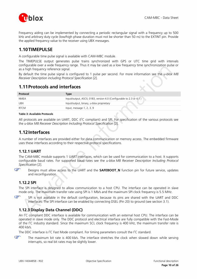
Frequency aiding can be implemented by connecting a periodic rectangular signal with a frequency up to 500 kHz and arbitrary duty cycle (low/high phase duration must not be shorter than 50 ns) to the EXTINT pin. Provide the applied frequency value to the receiver using UBX messages.
1.10 TIMEPULSE A configurable time pulse signal is available with CAM-M8C module.
The TIMEPULSE output generates pulse trains synchronized with GPS or UTC time grid with intervals configurable over a wide frequency range. Thus it may be used as a low frequency time synchronization pulse or as a high frequency reference signal.
By default the time pulse signal is configured to 1 pulse per second. For more information see the u-blox M8 Receiver Description including Protocol Specification [2].
1.11 Protocols and interfaces Protocol Type
NMEA Input/output, ASCII, 0183, version 4.0 (Configurable to 2.3 or 4.1 )
UBX Input/output, binary, u-blox proprietary
RTCM Input, message 1, 2, 3, 9
Table 3: Available Protocols
All protocols are available on UART, DDC (I2C compliant) and SPI. For specification of the various protocols see the u-blox M8 Receiver Description Including Protocol Specification [2].
1.12 Interfaces A number of interfaces are provided either for data communication or memory access. The embedded firmware uses these interfaces according to their respective protocol specifications.
1.12.1 UART The CAM-M8C module supports 1 UART interfaces, which can be used for communication to a host. It supports configurable baud rates. For supported baud rates see the u-blox M8 Receiver Description Including Protocol Specification [2].
Designs must allow access to the UART and the SAFEBOOT_N function pin for future service, updates and reconfiguration.
1.12.2 SPI The SPI interface is designed to allow communication to a host CPU. The interface can be operated in slave mode only. The maximum transfer rate using SPI is 1 Mb/s and the maximum SPI clock frequency is 5.5 MHz.
SPI is not available in the default configuration, because its pins are shared with the UART and DDC interfaces. The SPI interface can be enabled by connecting DSEL (Pin 20) to ground (see section 3.1).
1.12.3 Display Data Channel (DDC) An I2C compliant DDC interface is available for communication with an external host CPU. The interface can be operated in slave mode only. The DDC protocol and electrical interface are fully compatible with the Fast-Mode of the I2C industry standard. Since the maximum SCL clock frequency is 400 kHz, the maximum transfer rate is 400 kb/s.
The DDC interface is I2C Fast Mode compliant. For timing parameters consult the I2C standard.
The maximum bit rate is 400 kb/s. The interface stretches the clock when slowed down while serving interrupts, so real bit rates may be slightly lower.
CAM-M8C - Data Sheet
UBX-14044858 - R02 Objective Specification Functional description
Page 11 of 26
1.13 Clock generation
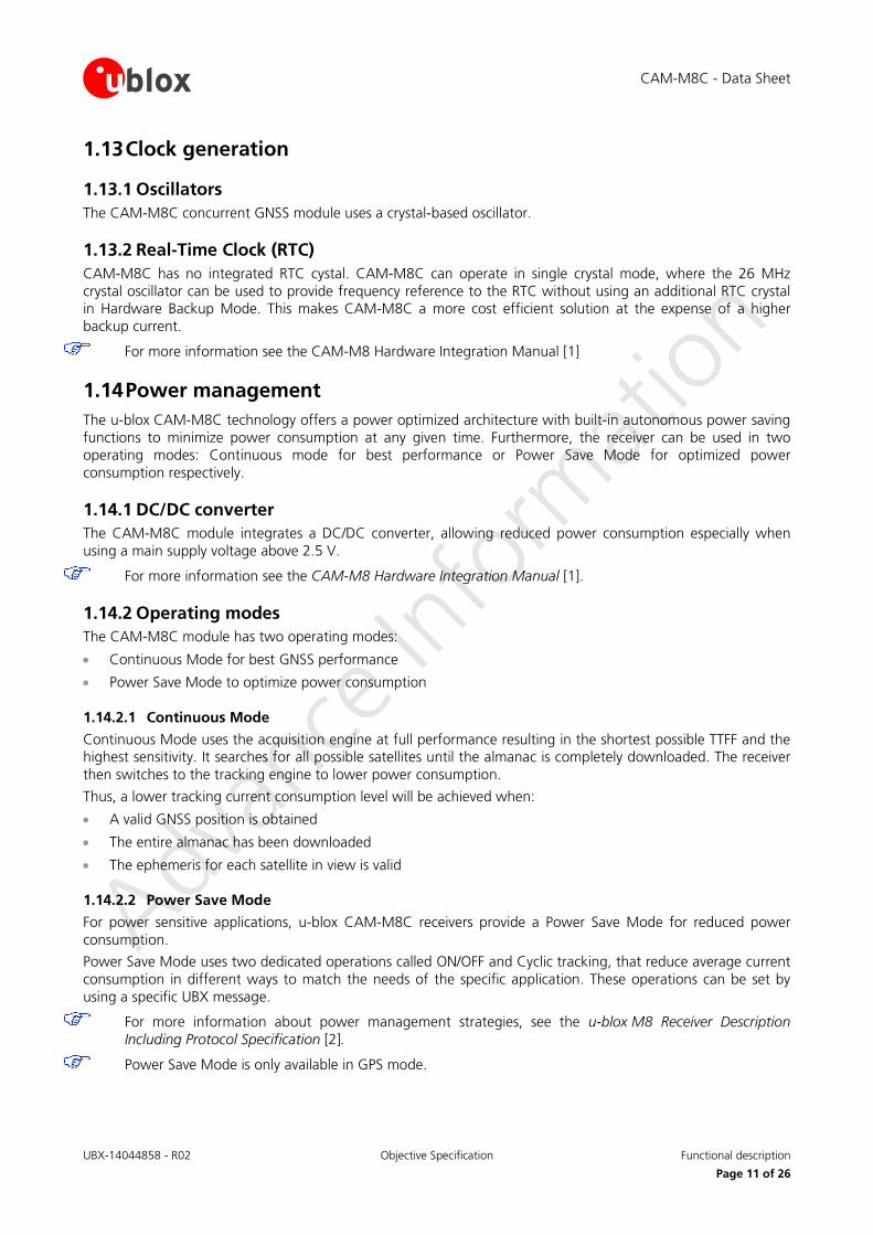
1.13.1 Oscillators The CAM-M8C concurrent GNSS module uses a crystal-based oscillator.
1.13.2 Real-Time Clock (RTC) CAM-M8C has no integrated RTC cystal. CAM-M8C can operate in single crystal mode, where the 26 MHz crystal oscillator can be used to provide frequency reference to the RTC without using an additional RTC crystal in Hardware Backup Mode. This makes CAM-M8C a more cost efficient solution at the expense of a higher backup current.
For more information see the CAM-M8 Hardware Integration Manual [1]
1.14 Power management The u-blox CAM-M8C technology offers a power optimized architecture with built-in autonomous power saving functions to minimize power consumption at any given time. Furthermore, the receiver can be used in two operating modes: Continuous mode for best performance or Power Save Mode for optimized power consumption respectively.
1.14.1 DC/DC converter The CAM-M8C module integrates a DC/DC converter, allowing reduced power consumption especially when using a main supply voltage above 2.5 V.
For more information see the CAM-M8 Hardware Integration Manual [1].
1.14.2 Operating modes The CAM-M8C module has two operating modes:
• Continuous Mode for best GNSS performance
• Power Save Mode to optimize power consumption
1.14.2.1 Continuous Mode
Continuous Mode uses the acquisition engine at full performance resulting in the shortest possible TTFF and the highest sensitivity. It searches for all possible satellites until the almanac is completely downloaded. The receiver then switches to the tracking engine to lower power consumption.
Thus, a lower tracking current consumption level will be achieved when:
• A valid GNSS position is obtained
• The entire almanac has been downloaded
• The ephemeris for each satellite in view is valid
1.14.2.2 Power Save Mode
For power sensitive applications, u-blox CAM-M8C receivers provide a Power Save Mode for reduced power consumption.
Power Save Mode uses two dedicated operations called ON/OFF and Cyclic tracking, that reduce average current consumption in different ways to match the needs of the specific application. These operations can be set by using a specific UBX message.
For more information about power management strategies, see the u-blox M8 Receiver Description Including Protocol Specification [2].
Power Save Mode is only available in GPS mode.
CAM-M8C - Data Sheet
UBX-14044858 - R02 Objective Specification Functional description
Page 12 of 26
1.15 Antenna The CAM-M8C concurrent GNSS module is designed with integrated GNSS chip antenna. Optionally, CAM-M8C can be connected to an external GNSS antenna.
Because the customer PCB is used as a part of antenna, some important PCB layout design rules should be followed in order to maintain good performance of the on-board GNSS chip antenna. For more information see the CAM-M8 Hardware Integration Manual [1].
1.15.1 Embedded Antenna The CAM-M8C module has an embedded GNSS antenna and the signal is further filtered and amplified by internal Low Noise Amplifier (LNA), which is available at ANT output. The antenna signal ANT shall be connected externally to RF_IN Antenna Input signal via a short trace between pads. For more information see the CAM-M8 Hardware Integration Manual [1].
1.15.2 External GPS/GLONASS antenna connectivity The customer may use an external active GNSS antenna connected via an external RF-switch. It is suggested that the active antenna has a net gain including cable loss in the range from +10 dB to +30 dB. Specified sensitivity is measured with external low noise (NF < 1dB, G > 15dB) amplifier. The antenna shall provide simultaneous reception of both GPS 1575 MHz and GLONASS bands 1598 to 1606 MHz.
External passive antenna is not recommended. For more information concerning external antenna option, see the CAM-M8 Hardware Integration Manual [1].
1.15.3 Active antenna control (ANTON) The ANTON Pin can be used to turn on and off an external LNA or an active antenna. This reduces power consumption in Power Save Mode (Backup mode).
When ANTON Pin is used externally, an external pull down resistor should be connected at ANTON signal. For more information see the CAM-M8 Hardware Integration Manual [1]
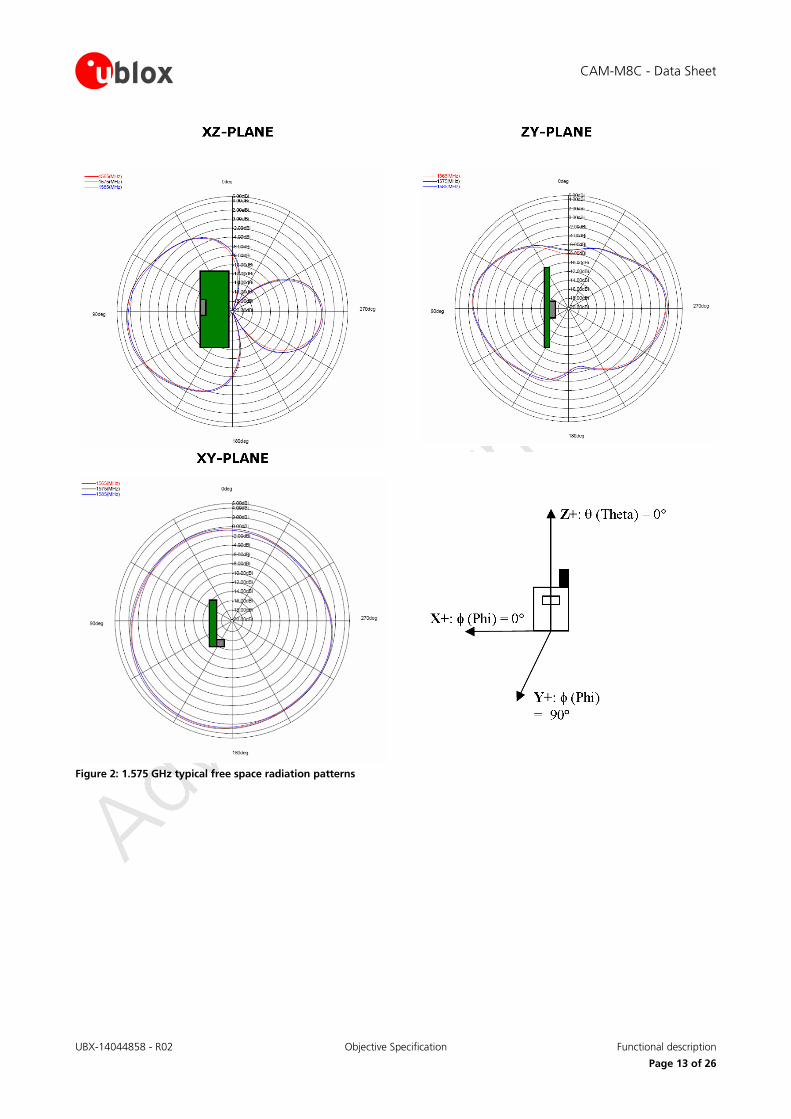
1.15.4 Embedded antenna operation The embedded GNSS chip antenna provides optimal radiation efficiency 80% typ. with 80x40 mm ground plane. The GNSS chip antenna provides linear polarization with peak gain 1.1 dBi and radiation pattern optimized for portable devices. The chip antenna is insensitive to surroundings and has high tolerance against frequency shifts. Figure 2 shows the typical free space radiation patterns of the embedded GNSS chip antenna at 1575 GHz. However, on small ground plane widths, the antenna gain and radiation efficiency is reduced.
CAM-M8C - Data Sheet
UBX-14044858 - R02 Objective Specification Functional description
Page 13 of 26
Figure 2: 1.575 GHz typical free space radiation patterns
CAM-M8C - Data Sheet
UBX-14044858 - R02 Objective Specification Pin Definition
Page 14 of 26
2 Pin Definition
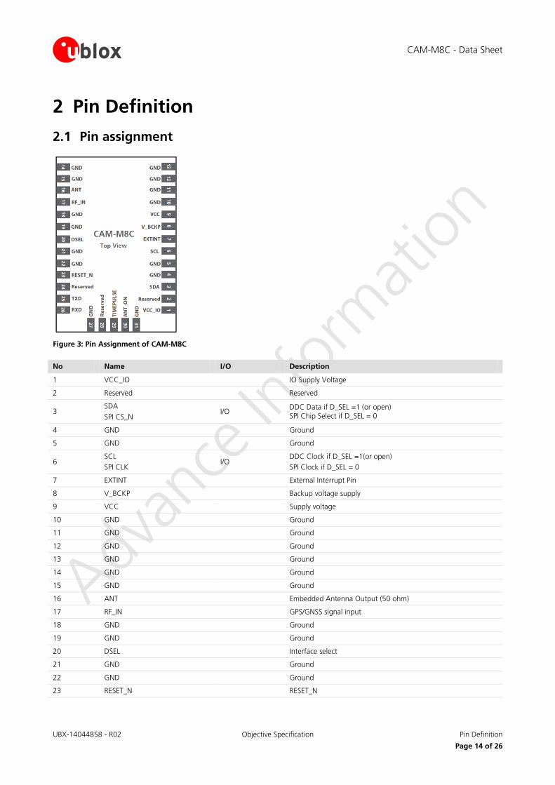
2.1 Pin assignment
Figure 3: Pin Assignment of CAM-M8C
No Name I/O Description
1 VCC_IO IO Supply Voltage
2 Reserved Reserved
3 SDA SPI CS_N
I/O DDC Data if D_SEL =1 (or open) SPI Chip Select if D_SEL = 0
4 GND Ground
5 GND Ground
6 SCL SPI CLK
I/O DDC Clock if D_SEL =1(or open) SPI Clock if D_SEL = 0
7 EXTINT External Interrupt Pin
8 V_BCKP Backup voltage supply
9 VCC Supply voltage
10 GND Ground
11 GND Ground
12 GND Ground
13 GND Ground
14 GND Ground
15 GND Ground
16 ANT Embedded Antenna Output (50 ohm)
17 RF_IN GPS/GNSS signal input
18 GND Ground
19 GND Ground
20 DSEL Interface select
21 GND Ground
22 GND Ground
23 RESET_N RESET_N
CAM-M8C - Data Sheet
UBX-14044858 - R02 Objective Specification Pin Definition
Page 15 of 26
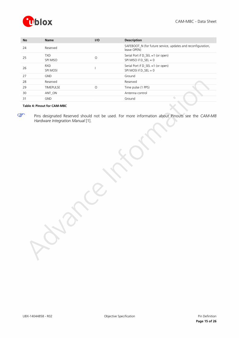
No Name I/O Description
24 Reserved SAFEBOOT_N (for future service, updates and reconfiguration, leave OPEN)
25 TXD SPI MISO
O Serial Port if D_SEL =1 (or open) SPI MISO if D_SEL = 0
26 RXD SPI MOSI
I Serial Port if D_SEL =1 (or open) SPI MOSI if D_SEL = 0
27 GND Ground
28 Reserved Reserved
29 TIMEPULSE O Time pulse (1 PPS)
30 ANT_ON Antenna control
31 GND Ground
Table 4: Pinout for CAM-M8C
Pins designated Reserved should not be used. For more information about Pinouts see the CAM-M8 Hardware Integration Manual [1].
CAM-M8C - Data Sheet
UBX-14044858 - R02 Objective Specification Configuration management
Page 16 of 26
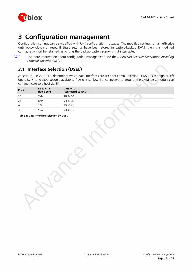
3 Configuration management Configuration settings can be modified with UBX configuration messages. The modified settings remain effective until power-down or reset. If these settings have been stored in battery-backup RAM, then the modified configuration will be retained, as long as the backup battery supply is not interrupted.
For more information about configuration management, see the u-blox M8 Receiver Description including Protocol Specification [2].
3.1 Interface Selection (DSEL) At startup, Pin 20 (DSEL) determines which data interfaces are used for communication. If DSEL is set high or left open, UART and DDC become available. If DSEL is set low, i.e. connected to ground, the CAM-M8C module can communicate to a host via SPI.
PIN # DSEL = ”1” (left open)
DSEL = ”0” (connected to GND)
25 TXD SPI MISO
26 RXD SPI MOSI
6 SCL SPI CLK
3 SDA SPI CS_N
Table 5: Data interface selection by DSEL
CAM-M8C - Data Sheet
UBX-14044858 - R02 Objective Specification Electrical specification
Page 17 of 26
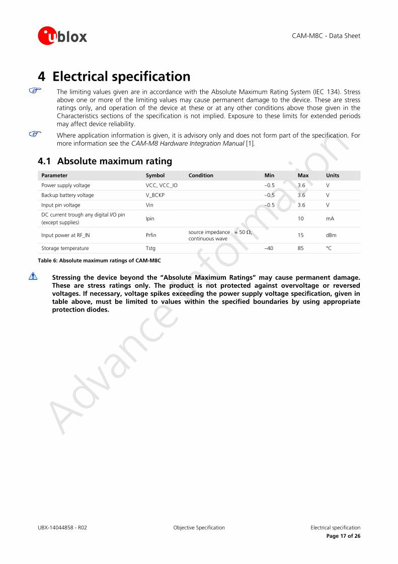
4 Electrical specification The limiting values given are in accordance with the Absolute Maximum Rating System (IEC 134). Stress
above one or more of the limiting values may cause permanent damage to the device. These are stress ratings only, and operation of the device at these or at any other conditions above those given in the Characteristics sections of the specification is not implied. Exposure to these limits for extended periods may affect device reliability.
Where application information is given, it is advisory only and does not form part of the specification. For more information see the CAM-M8 Hardware Integration Manual [1].
4.1 Absolute maximum rating Parameter Symbol Condition Min Max Units
Power supply voltage VCC, VCC_IO –0.5 3.6 V
Backup battery voltage V_BCKP –0.5 3.6 V
Input pin voltage Vin –0.5 3.6 V
DC current trough any digital I/O pin (except supplies)
Ipin 10 mA
Input power at RF_IN Prfin source impedance = 50 Ω, continuous wave
15 dBm
Storage temperature Tstg –40 85 °C
Table 6: Absolute maximum ratings of CAM-M8C
Stressing the device beyond the “Absolute Maximum Ratings” may cause permanent damage. These are stress ratings only. The product is not protected against overvoltage or reversed voltages. If necessary, voltage spikes exceeding the power supply voltage specification, given in table above, must be limited to values within the specified boundaries by using appropriate protection diodes.
CAM-M8C - Data Sheet
UBX-14044858 - R02 Objective Specification Electrical specification
Page 18 of 26
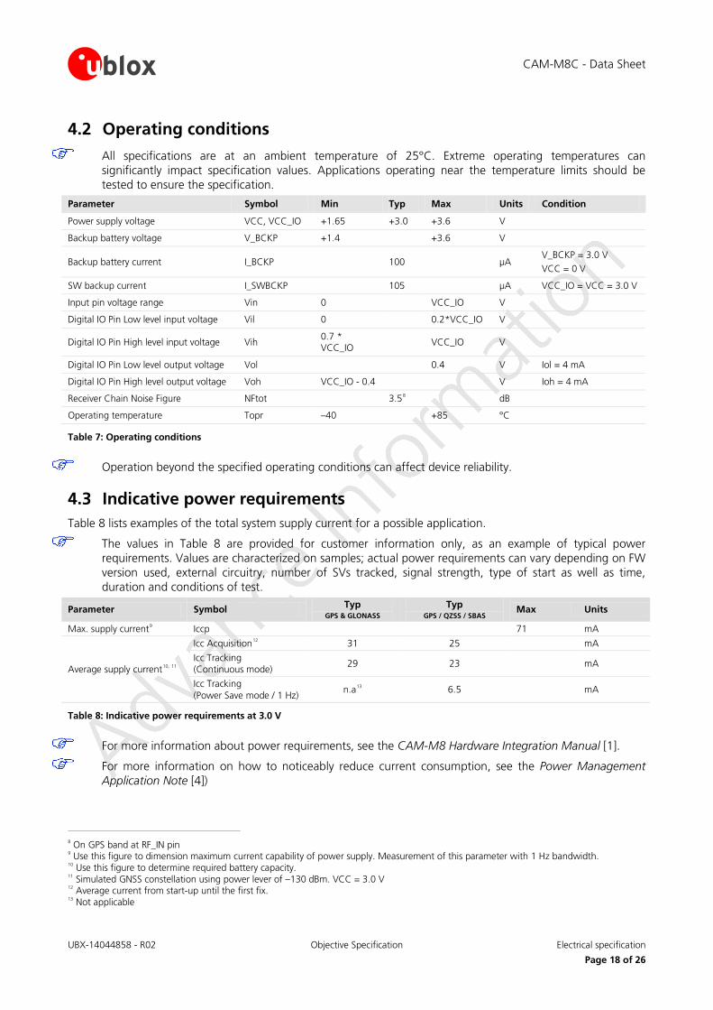
4.2 Operating conditions
All specifications are at an ambient temperature of 25°C. Extreme operating temperatures can significantly impact specification values. Applications operating near the temperature limits should be tested to ensure the specification.
Parameter Symbol Min Typ Max Units Condition
Power supply voltage VCC, VCC_IO +1.65 +3.0 +3.6 V
Backup battery voltage V_BCKP +1.4 +3.6 V
Backup battery current I_BCKP 100 µA V_BCKP = 3.0 V VCC = 0 V
SW backup current I_SWBCKP 105 µA VCC_IO = VCC = 3.0 V
Input pin voltage range Vin 0 VCC_IO V
Digital IO Pin Low level input voltage Vil 0 0.2*VCC_IO V
Digital IO Pin High level input voltage Vih 0.7 * VCC_IO
VCC_IO V
Digital IO Pin Low level output voltage Vol 0.4 V Iol = 4 mA
Digital IO Pin High level output voltage Voh VCC_IO - 0.4 V Ioh = 4 mA
Receiver Chain Noise Figure NFtot 3.58 dB
Operating temperature Topr –40 +85 °C
Table 7: Operating conditions
Operation beyond the specified operating conditions can affect device reliability.
4.3 Indicative power requirements Table 8 lists examples of the total system supply current for a possible application.
The values in Table 8 are provided for customer information only, as an example of typical power requirements. Values are characterized on samples; actual power requirements can vary depending on FW version used, external circuitry, number of SVs tracked, signal strength, type of start as well as time, duration and conditions of test.
Parameter Symbol Typ GPS & GLONASS
Typ GPS / QZSS / SBAS
Max Units
Max. supply current9 Iccp 71 mA
Average supply current10, 11
Icc Acquisition12 31 25 mA
Icc Tracking (Continuous mode)
29 23 mA
Icc Tracking (Power Save mode / 1 Hz)
n.a13 6.5 mA
Table 8: Indicative power requirements at 3.0 V
For more information about power requirements, see the CAM-M8 Hardware Integration Manual [1].
For more information on how to noticeably reduce current consumption, see the Power Management Application Note [4])
8 On GPS band at RF_IN pin 9 Use this figure to dimension maximum current capability of power supply. Measurement of this parameter with 1 Hz bandwidth. 10 Use this figure to determine required battery capacity. 11 Simulated GNSS constellation using power lever of –130 dBm. VCC = 3.0 V 12 Average current from start-up until the first fix. 13 Not applicable
UBX-14044858 - R02 Objective Specification Mechanical specifications Page 19 of 26
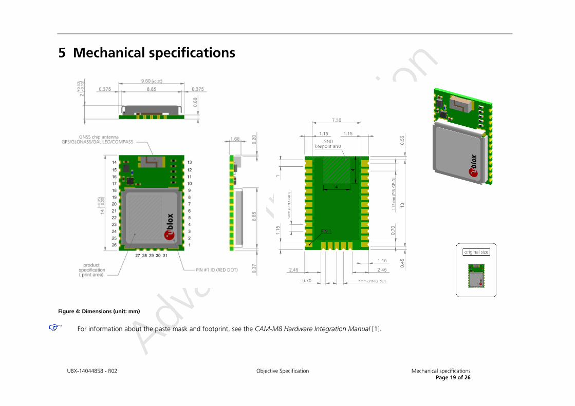
5 Mechanical specifications
Figure 4: Dimensions (unit: mm)
For information about the paste mask and footprint, see the CAM-M8 Hardware Integration Manual [1].
CAM-M8C - Data Sheet
UBX-14044858 - R02 Objective Specification Reliability tests and approvals
Page 20 of 26
6 Reliability tests and approvals
6.1 Reliability tests
The CAM-M8C concurrent GNSS antenna module is based on AEC-Q100 qualified GNSS chips.
Tests for product qualifications are according to ISO 16750 "Road vehicles – Environmental conditions and testing for electrical and electronic equipment”, and appropriate standards.
6.2 Approvals
Products marked with this lead-free symbol on the product label comply with the "Directive 2002/95/EC of the European Parliament and the Council on the Restriction of Use of certain Hazardous Substances in Electrical and Electronic Equipment" (RoHS).
u-blox CAM-M8C concurrent GNSS antenna modules are RoHS compliant.
CAM-M8C - Data Sheet
UBX-14044858 - R02 Objective Specification Product handling & soldering
Page 21 of 26
7 Product handling & soldering
7.1 Packaging The CAM-M8C modules are delivered as hermetically sealed, reeled tapes in order to enable efficient production, production lot set-up and tear-down. For more information see the u-blox Package Information Guide [3].
7.1.1 Reels The CAM-M8C GPS modules are deliverable in quantities of 500 pcs on a reel. The CAM-M8C modules are shipped on Reel Type B, as specified in the u-blox Package Information Guide [3].
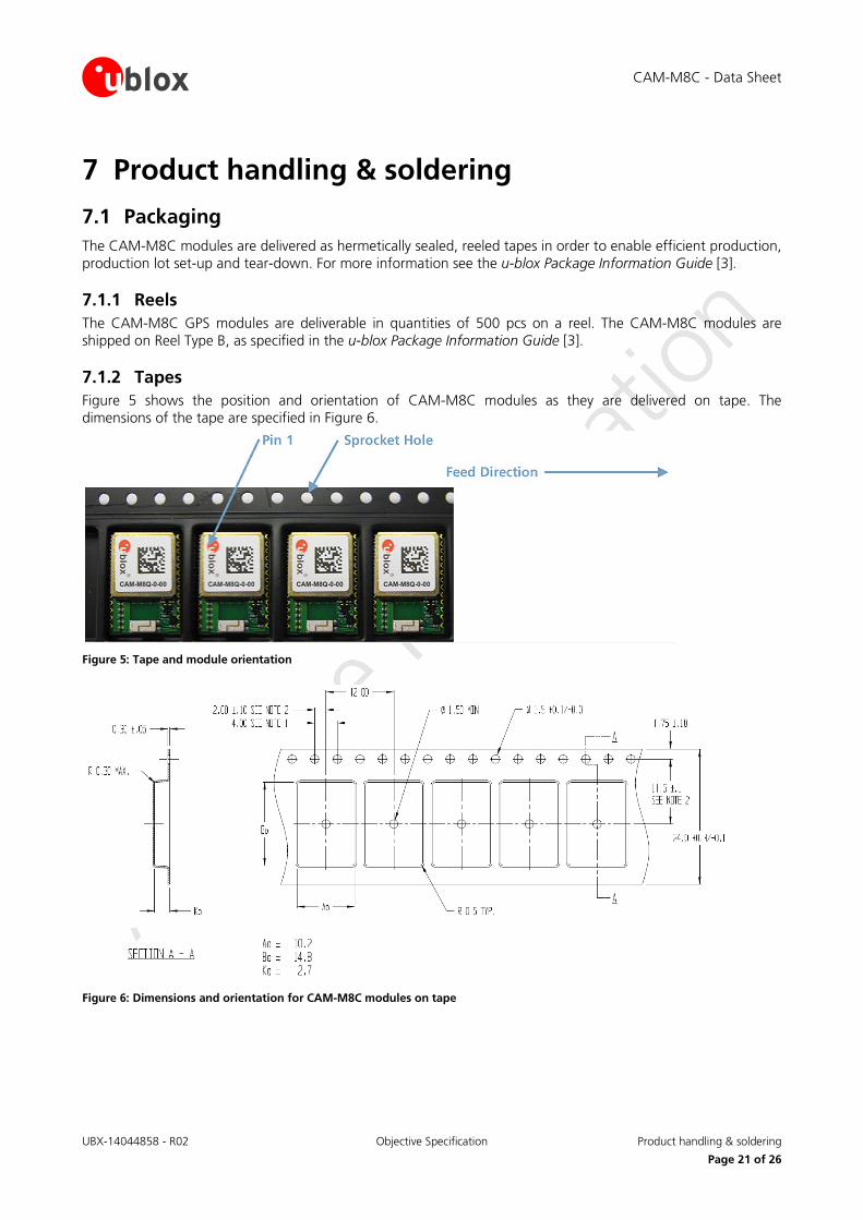
7.1.2 Tapes Figure 5 shows the position and orientation of CAM-M8C modules as they are delivered on tape. The dimensions of the tape are specified in Figure 6.
Figure 5: Tape and module orientation
Figure 6: Dimensions and orientation for CAM-M8C modules on tape
CAM-M8C - Data Sheet
UBX-14044858 - R02 Objective Specification Product handling & soldering
Page 22 of 26
7.2 Shipment, storage and handling For important information about shipment, storage and handling, see the u-blox Package Information Guide [3].
7.2.1 Moisture Sensitivity Levels The Moisture Sensitivity Level (MSL) relates to the packaging and handling precautions required. CAM-M8C modules are rated at MSL level 4.
For MSL standard see IPC/JEDEC J-STD-020. Download available at www.jedec.org.
For more information regarding MSL, see the u-blox Package Information Guide [3].
7.2.2 Reflow soldering Reflow profiles are to be selected according u-blox recommendations (see the CAM-M8C Hardware Integration Manual [1]).
7.2.3 Antenna aging Antenna electrode metallization is unprotected silver and will tarnish during storage due to sulfuric compounds present in the atmosphere. Elevated temperature and humidity will accelerate this process. Human skin contact, wool etc. will also cause tarnishing. This has no effect on the electrical performance of the antenna. u-blox accepts no warranty claims for tarnished products due to this normal and to be expected process.
7.2.4 ESD handling precautions
CAM-M8C modules are Electrostatic Sensitive Devices (ESD). Observe handling precautions! Failure to observe these precautions can result in severe damage to the GNSS receiver!
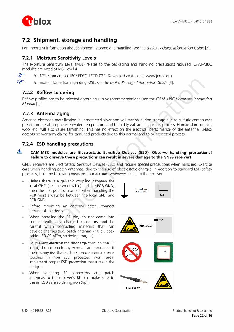
GNSS receivers are Electrostatic Sensitive Devices (ESD) and require special precautions when handling. Exercise care when handling patch antennas, due to the risk of electrostatic charges. In addition to standard ESD safety practices, take the following measures into account whenever handling the receiver:
• Unless there is a galvanic coupling between the local GND (i.e. the work table) and the PCB GND, then the first point of contact when handling the PCB must always be between the local GND and PCB GND.
• Before mounting an antenna patch, connect ground of the device
• When handling the RF pin, do not come into contact with any charged capacitors and be careful when contacting materials that can develop charges (e.g. patch antenna ~10 pF, coax cable ~50-80 pF/m, soldering iron, …)
• To prevent electrostatic discharge through the RF input, do not touch any exposed antenna area. If there is any risk that such exposed antenna area is touched in non ESD protected work area, implement proper ESD protection measures in the design.
• When soldering RF connectors and patch antennas to the receiver’s RF pin, make sure to use an ESD safe soldering iron (tip).
CAM-M8C - Data Sheet
UBX-14044858 - R02 Objective Specification Default messages
Page 23 of 26
8 Default messages Interface Settings
UART Output
9600 Baud, 8 bits, no parity bit, 1 stop bit Configured to transmit both NMEA and UBX protocols, but no UBX messages and only the following NMEA have been activated at start-up: GGA, GLL, GSA, GSV, RMC, VTG, TXT
UART Input 9600 Baud, 8 bits, no parity bit, 1 stop bit, Autobauding disabled Automatically accepts following protocols without need of explicit configuration: UBX, NMEA, RTCM The GPS receiver supports interleaved UBX and NMEA messages.
DDC Fully compatible with the I2C industry standard, available for communication with an external host CPU or u-blox cellular modules, operated in slave mode only. NMEA and UBX are enabled as input messages, only NMEA as output messages Maximum bit rate 400 kb/s.
TIMEPULSE (1 Hz Nav)
1 pulse per second, synchronized at rising edge, pulse length 100 ms
Table 9: Default messages
Refer to the u-blox M8 Receiver Description including Protocol Specification [2] for information about further settings.
CAM-M8C - Data Sheet
UBX-14044858 - R02 Objective Specification Labeling and ordering information
Page 24 of 26
9 Labeling and ordering information
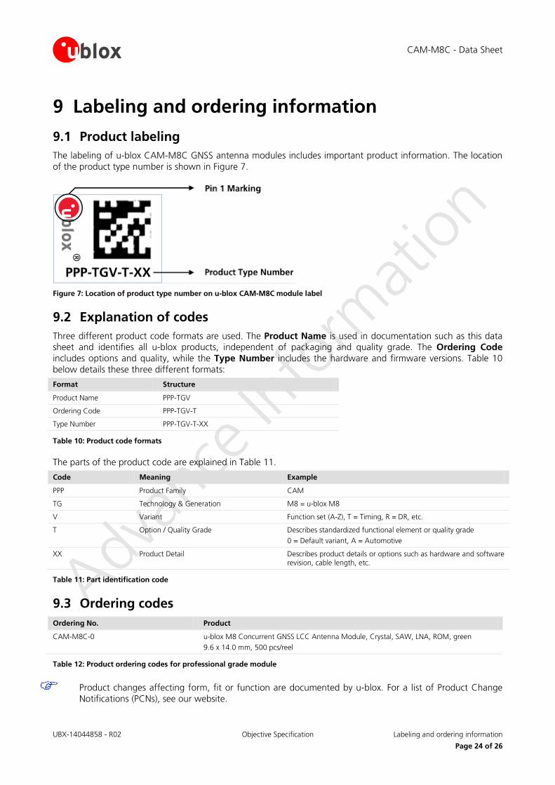
9.1 Product labeling The labeling of u-blox CAM-M8C GNSS antenna modules includes important product information. The location of the product type number is shown in Figure 7.
Figure 7: Location of product type number on u-blox CAM-M8C module label
9.2 Explanation of codes Three different product code formats are used. The Product Name is used in documentation such as this data sheet and identifies all u-blox products, independent of packaging and quality grade. The Ordering Code includes options and quality, while the Type Number includes the hardware and firmware versions. Table 10 below details these three different formats:
Format Structure
Product Name PPP-TGV
Ordering Code PPP-TGV-T
Type Number PPP-TGV-T-XX
Table 10: Product code formats
The parts of the product code are explained in Table 11.
Code Meaning Example
PPP Product Family CAM
TG Technology & Generation M8 = u-blox M8
V Variant Function set (A-Z), T = Timing, R = DR, etc.
T Option / Quality Grade Describes standardized functional element or quality grade 0 = Default variant, A = Automotive
XX Product Detail Describes product details or options such as hardware and software revision, cable length, etc.
Table 11: Part identification code
9.3 Ordering codes Ordering No. Product
CAM-M8C-0 u-blox M8 Concurrent GNSS LCC Antenna Module, Crystal, SAW, LNA, ROM, green 9.6 x 14.0 mm, 500 pcs/reel
Table 12: Product ordering codes for professional grade module
Product changes affecting form, fit or function are documented by u-blox. For a list of Product Change Notifications (PCNs), see our website.
CAM-M8C - Data Sheet
UBX-14044858 - R02 Objective Specification Related documents
Page 25 of 26
Related documents [1] CAM-M8 Hardware Integration Manual, Docu. No. UBX-14000014
[2] u-blox M8 Receiver Description Including Protocol Specification (Public version), Docu. No. UBX-13003221
[3] u-blox Package Information Guide, Docu. No. UBX-14001652
[4] Power Management Application Note, Docu. No. UBX-13005162
For regular updates to u-blox documentation and to receive product change notifications, register on our homepage.
Revision history Revision Date Name Status / Comments
R01 11-Feb-2015 julu Objective Specification
R02 10-Apr-2015 julu Advance Information
CAM-M8C - Data Sheet
UBX-14044858 - R02 Objective Specification Contact
Page 26 of 26
Contact For complete contact information visit us at www.u-blox.com
u-blox Offices
North, Central and South America
u-blox America, Inc.
Phone: +1 703 483 3180 E-mail: [email protected]
Regional Office West Coast:
Phone: +1 408 573 3640 E-mail: [email protected]
Technical Support:
Phone: +1 703 483 3185 E-mail: [email protected]
Headquarters Europe, Middle East, Africa
u-blox AG
Phone: +41 44 722 74 44 E-mail: [email protected] Support: [email protected]
Asia, Australia, Pacific
u-blox Singapore Pte. Ltd.
Phone: +65 6734 3811 E-mail: [email protected] Support: [email protected]
Regional Office Australia:
Phone: +61 2 8448 2016 E-mail: [email protected] Support: [email protected]
Regional Office China (Beijing):
Phone: +86 10 68 133 545 E-mail: [email protected] Support: [email protected]
Regional Office China (Shenzhen):
Phone: +86 755 8627 1083 E-mail: [email protected] Support: [email protected]
Regional Office India:
Phone: +91 959 1302 450 E-mail: [email protected] Support: [email protected]
Regional Office Japan:
Phone: +81 3 5775 3850 E-mail: [email protected] Support: [email protected]
Regional Office Korea:
Phone: +82 2 542 0861 E-mail: [email protected] Support: [email protected]
Regional Office Taiwan:
Phone: +886 2 2657 1090 E-mail: [email protected] Support: [email protected]