Embed Size (px)
Citation preview
EVA-7M u-blox 7 GNSS module Data Sheet
Highlights:
• Industry’s smallest standalone GPS/QZSS,GLONASS module
• Minimal system cost
• Minimal power consumption
• Eases design and manufacturing
• No host integration or external components needed
www.u-blox.com
UBX-13000581 - R07
EVA-7M - Data Sheet
UBX-13000581 - R07 Production Information Page 2 of 27
Document Information
Title EVA-7M
Subtitle u-blox 7 GNSS module
Document type Data Sheet
Document number UBX-13000581
Revision and date R07 30-Jan-2015
Document status Production Information
Document status explanation
Objective Specification Document contains target values. Revised and supplementary data will be published later.
Advance Information Document contains data based on early testing. Revised and supplementary data will be published later.
Early Production Information Document contains data from product verification. Revised and supplementary data may be published later.
Production Information Document contains the final product specification.
This document applies to the following products:
Product name Type number ROM/FLASH version PCN reference
EVA-7M EVA-7M-0-000 ROM 1.00 N/A
u-blox reserves all rights to this document and the information contained herein. Products, names, logos and designs described herein may in whole or in part be subject to intellectual property rights. Reproduction, use, modification or disclosure to third parties of this document or any part thereof without the express permission of u-blox is strictly prohibited. The information contained herein is provided “as is” and u-blox assumes no liability for the use of the information. No warranty, either express or implied, is given, including but not limited, with respect to the accuracy, correctness, reliability and fitness for a particular purpose of the information. This document may be revised by u-blox at any time. For most recent documents, visit www.u-blox.com. Copyright © 2014, u-blox AG. u-blox® is a registered trademark of u-blox Holding AG in the EU and other countries. ARM® is the registered trademark of ARM Limited in the EU and other countries.
EVA-7M - Data Sheet
UBX-13000581 - R07 Production Information Contents
Page 3 of 27
Contents Contents .............................................................................................................................. 3
1 Functional description .................................................................................................. 5 1.1 Overview .............................................................................................................................................. 5 1.2 Highlights ............................................................................................................................................. 5 1.3 Product features ................................................................................................................................... 5 1.4 GNSS Performance ............................................................................................................................... 6 1.5 Block diagram ....................................................................................................................................... 7 1.6 GNSS .................................................................................................................................................... 7
1.6.1 GPS ............................................................................................................................................... 7 1.6.2 GLONASS ...................................................................................................................................... 7 1.6.3 QZSS ............................................................................................................................................. 7
1.7 Augmentation Systems ......................................................................................................................... 8 1.7.1 Assisted GNSS (A-GNSS) ................................................................................................................ 8 1.7.2 Satellite-Based Augmentation System (SBAS) ................................................................................. 8 1.7.3 Differential GPS (D-GPS) ................................................................................................................ 8
1.8 EXTINT: External interrupt ..................................................................................................................... 9 1.8.1 Pin Control .................................................................................................................................... 9 1.8.2 Aiding ........................................................................................................................................... 9
1.9 TIMEPULSE ........................................................................................................................................... 9 1.10 Protocols and interfaces .................................................................................................................... 9 1.11 Interfaces .......................................................................................................................................... 9
1.11.1 UART ............................................................................................................................................. 9 1.11.2 USB ............................................................................................................................................. 10 1.11.3 SPI ............................................................................................................................................... 10 1.11.4 Display Data Channel (DDC) ........................................................................................................ 10 1.11.5 Interface selection (D_SEL) ........................................................................................................... 10
1.12 Configurable Input Output pins ...................................................................................................... 10 1.13 System reset .................................................................................................................................... 10 1.14 Clock generation ............................................................................................................................ 11
1.14.1 Oscillator ..................................................................................................................................... 11 1.14.2 Real-Time Clock (RTC) ................................................................................................................. 11
1.15 Power Management ....................................................................................................................... 11 1.15.1 DC/DC converter ......................................................................................................................... 11 1.15.2 Operating modes ........................................................................................................................ 11
1.16 Antenna .......................................................................................................................................... 12 1.16.1 Active antenna control (ANT_OFF) ............................................................................................... 12 1.16.2 Active Antenna supervisor and short circuit detection.................................................................. 12
2 Pin definition .............................................................................................................. 13 2.1 Pin assignment ................................................................................................................................... 13
EVA-7M - Data Sheet
UBX-13000581 - R07 Production Information Contents
Page 4 of 27
3 Electrical specification ................................................................................................ 15 3.1 Absolute maximum rating .................................................................................................................. 15 3.2 Operating conditions .......................................................................................................................... 16
3.2.1 Normal operating temperature range .......................................................................................... 16 3.2.2 Extended operating temperature range 1 .................................................................................... 16 3.2.3 DC electrical characteristic ........................................................................................................... 17
3.3 Indicative power requirements ............................................................................................................ 18 3.4 SPI timing diagrams ............................................................................................................................ 19
3.4.1 Timing recommendations ............................................................................................................ 19
4 Mechanical specification ............................................................................................ 20
5 Reliability tests and approvals .................................................................................. 21 5.1 Reliability tests .................................................................................................................................... 21 5.2 Approvals ........................................................................................................................................... 21
6 Product handling ........................................................................................................ 22 6.1 Packaging ........................................................................................................................................... 22
6.1.1 Reels ........................................................................................................................................... 22 6.1.2 Tapes .......................................................................................................................................... 22
6.2 Moisture Sensitivity Levels ................................................................................................................... 23 6.3 ESD handling precautions ................................................................................................................... 23
7 Default messages ....................................................................................................... 24
8 Labeling and ordering information ........................................................................... 25 8.1 Product labeling .................................................................................................................................. 25 8.2 Explanation of product codes ............................................................................................................. 25 8.3 Ordering codes ................................................................................................................................... 25
Related documents........................................................................................................... 26
Revision history ................................................................................................................ 26
Contact .............................................................................................................................. 27
EVA-7M - Data Sheet
UBX-13000581 - R07 Production Information Functional description
Page 5 of 27
1 Functional description
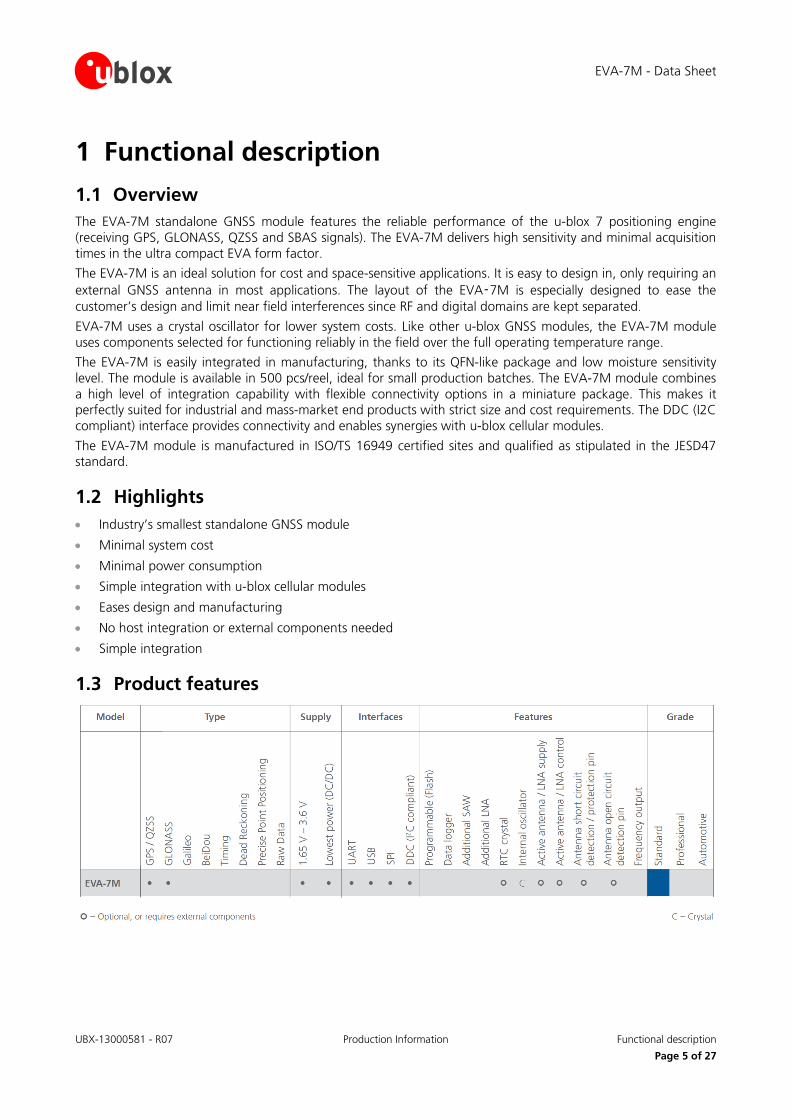
1.1 Overview The EVA-7M standalone GNSS module features the reliable performance of the u-blox 7 positioning engine (receiving GPS, GLONASS, QZSS and SBAS signals). The EVA-7M delivers high sensitivity and minimal acquisition times in the ultra compact EVA form factor.
The EVA-7M is an ideal solution for cost and space-sensitive applications. It is easy to design in, only requiring an external GNSS antenna in most applications. The layout of the EVA‑7M is especially designed to ease the customer’s design and limit near field interferences since RF and digital domains are kept separated.
EVA-7M uses a crystal oscillator for lower system costs. Like other u-blox GNSS modules, the EVA-7M module uses components selected for functioning reliably in the field over the full operating temperature range.
The EVA-7M is easily integrated in manufacturing, thanks to its QFN-like package and low moisture sensitivity level. The module is available in 500 pcs/reel, ideal for small production batches. The EVA-7M module combines a high level of integration capability with flexible connectivity options in a miniature package. This makes it perfectly suited for industrial and mass-market end products with strict size and cost requirements. The DDC (I2C compliant) interface provides connectivity and enables synergies with u-blox cellular modules.
The EVA-7M module is manufactured in ISO/TS 16949 certified sites and qualified as stipulated in the JESD47 standard.
1.2 Highlights • Industry’s smallest standalone GNSS module
• Minimal system cost
• Minimal power consumption
• Simple integration with u-blox cellular modules
• Eases design and manufacturing
• No host integration or external components needed
• Simple integration
1.3 Product features
EVA-7M - Data Sheet
UBX-13000581 - R07 Production Information Functional description
Page 6 of 27
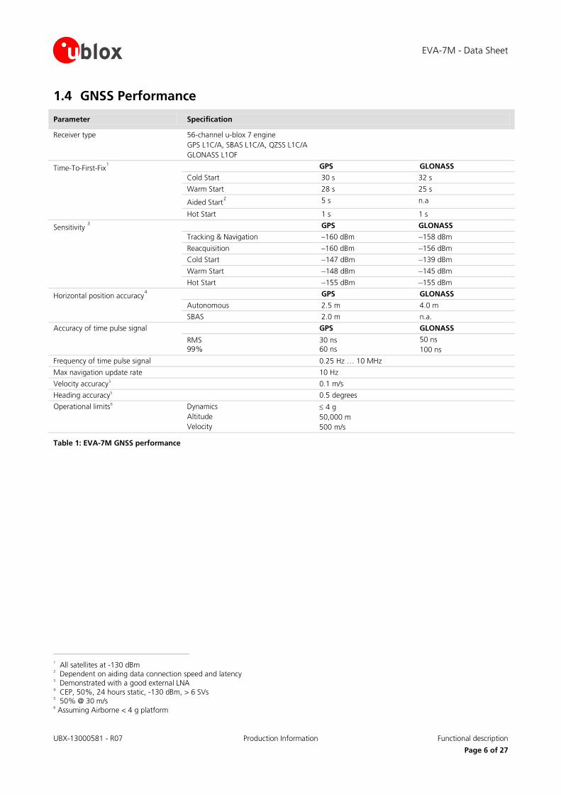
1.4 GNSS Performance
Parameter Specification
Receiver type 56-channel u-blox 7 engine GPS L1C/A, SBAS L1C/A, QZSS L1C/A GLONASS L1OF
Time-To-First-Fix1 GPS GLONASS
Cold Start 30 s 32 s
Warm Start 28 s 25 s
Aided Start2 5 s n.a
Hot Start 1 s 1 s
Sensitivity 3 GPS GLONASS
Tracking & Navigation –160 dBm –158 dBm
Reacquisition –160 dBm –156 dBm Cold Start –147 dBm –139 dBm
Warm Start –148 dBm –145 dBm
Hot Start –155 dBm –155 dBm
Horizontal position accuracy4 GPS GLONASS
Autonomous 2.5 m 4.0 m
SBAS 2.0 m n.a.
Accuracy of time pulse signal GPS GLONASS
RMS 99%
30 ns 60 ns
50 ns 100 ns
Frequency of time pulse signal 0.25 Hz … 10 MHz
Max navigation update rate 10 Hz
Velocity accuracy5 0.1 m/s
Heading accuracy5 0.5 degrees
Operational limits6 Dynamics Altitude Velocity
≤ 4 g 50,000 m 500 m/s
Table 1: EVA-7M GNSS performance
1 All satellites at -130 dBm 2 Dependent on aiding data connection speed and latency 3 Demonstrated with a good external LNA 4 CEP, 50%, 24 hours static, -130 dBm, > 6 SVs 5 50% @ 30 m/s 6 Assuming Airborne < 4 g platform
EVA-7M - Data Sheet
UBX-13000581 - R07 Production Information Functional description
Page 7 of 27
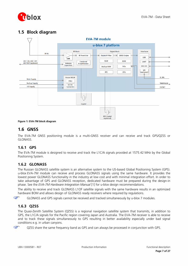
1.5 Block diagram
Figure 1: EVA-7M block diagram
1.6 GNSS The EVA-7M GNSS positioning module is a multi-GNSS receiver and can receive and track GPS/QZSS or GLONASS.
1.6.1 GPS The EVA-7M module is designed to receive and track the L1C/A signals provided at 1575.42 MHz by the Global Positioning System.
1.6.2 GLONASS The Russian GLONASS satellite system is an alternative system to the US-based Global Positioning System (GPS). u-blox EVA-7M module can receive and process GLONASS signals using the same hardware. It provides the lowest power GLONASS functionality in the industry at low cost and with minimal integration effort. In order to take advantage of GPS and GLONASS reception, dedicated hardware must be prepared during the design-in phase. See the EVA-7M Hardware Integration Manual [1] for u-blox design recommendations.
The ability to receive and track GLONASS L1OF satellite signals with the same hardware results in an optimized hardware BOM and allows design of GLONASS ready receivers where required by regulations.
GLONASS and GPS signals cannot be received and tracked simultaneously by u-blox 7 modules.
1.6.3 QZSS The Quasi-Zenith Satellite System (QZSS) is a regional navigation satellite system that transmits, in addition to GPS, the L1C/A signals for the Pacific region covering Japan and Australia. The EVA-7M receiver is able to receive and to track these signals simultaneously to GPS resulting in better availability especially under bad signal conditions e.g. in urban canyons.
QZSS share the same frequency band as GPS and can always be processed in conjunction with GPS.
EVA-7M - Data Sheet
UBX-13000581 - R07 Production Information Functional description
Page 8 of 27
1.7 Augmentation Systems
1.7.1 Assisted GNSS (A-GPS) A-GPS improves GNSS performance by delivering aiding data to the GNSS receiver via wireless networks or the Internet. Supplying information such as ephemeris, almanac, approximate last position, time and satellite status and an optional time synchronization signal significantly reduces Time to First Fix (TTFF) and improves acquisition sensitivity.
AssistNow Online and AssistNow Offline are u-blox’ end-to-end A-GPS services for devices with or without network connectivity. AssistNow Online and AssistNow Offline can either be used alone or in combination. They are very easy to implement, require no additional hardware, and generate virtually no CPU load. All u-blox 7 modules support u-blox’ AssistNow Online, AssistNow Offline and AssistNow Autonomous A-GPS services, and are OMA SUPL compliant.
AssistNow™ Online
With AssistNow Online, an internet-connected GNSS device downloads assistance data from u-blox’ AssistNow Online Service at system start-up. AssistNow Online is network operator independent and globally available. u-blox only sends ephemeris data for those satellites currently visible to the device requesting the data, thus minimizing the amount of data transferred.
AssistNow™ Offline
With AssistNow Offline, users download u-blox’ Differential Almanac Correction Data from the Internet at their convenience. The correction data can be stored in the memory of the application processor. Therefore, the service requires no connectivity at system start-up and enables a position fix within seconds, even when no network is available.
AssistNow™ Autonomous
AssistNow Autonomous provides functionality similar to Assisted-GPS without the need for a host or external network connection. It is an embedded feature available free-of-charge that accelerates GNSS positioning by capitalizing on the periodic nature of GPS satellite orbits. GPS orbit predictions are directly calculated by the GNSS receiver and no external aiding data or connectivity is required. AssistNow Autonomous can be used alone, or together with AssistNow Online or AssistNow Offline for increased positioning speed and accuracy.
For more details see the u-blox 7 Receiver Description Including Protocol Specification V14 [2].
1.7.2 Satellite-Based Augmentation System (SBAS) u-blox EVA-7M positioning module supports SBAS. These systems supplement GPS data with additional regional or wide area GPS augmentation data. The system broadcasts the augmentation data via satellite and this information can be used by GNSS receivers to improve the resulting GPS precision. SBAS satellites can be used as additional satellites for ranging (navigation), further enhancing precision. The following SBAS are supported with the EVA-7M: WAAS, EGNOS and MSAS.
For more details see the u-blox 7 Receiver Description Including Protocol Specification V14 [2].
1.7.3 Differential GPS (D-GPS) The EVA-7M receiver supports Differential-GPS data according to RTCM 10402.3: "RECOMMENDED STANDARDS FOR DIFFERENTIAL GNSS". The use of Differential-GPS data improves GPS position accuracy. RTCM cannot be used together with SBAS. The RTCM implementation supports the following RTCM 2.3 messages:
Message Type Description
1 Differential GPS Corrections
2 Delta Differential GPS Corrections
3 GPS Reference Station Parameters
9 GPS Partial Correction Set
Table 2: Supported RTCM 2.3 messages
For more details see the u-blox 7 Receiver Description Including Protocol Specification V14 [2].
EVA-7M - Data Sheet
UBX-13000581 - R07 Production Information Functional description
Page 9 of 27
1.8 EXTINT: External interrupt EXTINT is an external interrupt pin with fixed input voltage thresholds with respect to VCC_IO. It can be used for control of the receiver or for Aiding.
For more information about how to implement and configure these features, see the u-blox 7 Receiver Description including Protocol Specification V14 [2] and the EVA-7M Hardware Integration Manual [1].
1.8.1 Pin Control The pin control feature allows overriding the automatic active/inactive cycle of Power Save Mode. The state of the receiver can be controlled through the EXTINT pin.
The receiver can also be turned off and sent into Backup Mode using EXTINT when Power Save Mode is not active.
1.8.2 Aiding The EXTINT pin can be used to supply time or frequency aiding data to the receiver.
For time aiding, the time can be supplied using hardware time synchronization where an accurate time pulse is connected to the EXTINT pin.
Frequency aiding can be implemented by connecting a periodic rectangular signal with a frequency up to 500 kHz and arbitrary duty cycle (low/high phase duration must not be shorter than 50 ns) to the EXTINT pin, and providing the applied frequency value to the receiver using UBX messages.
1.9 TIMEPULSE A configurable time pulse signal is available with the EVA-7M modules.
The TIMEPULSE output generates pulse trains synchronized with GPS or UTC time grid with intervals configurable over a wide frequency range. Thus it may be used as a low frequency time synchronization pulse or as a high frequency reference signal.
By default the time pulse signal is configured to 1 pulse per second. For more information see the u-blox 7 Receiver Description including Protocol Specification V14 [2].
1.10 Protocols and interfaces
Protocol Type
NMEA Input/output, ASCII, 0183, 2.3 (compatible to 3.0)
UBX Input/output, binary, u-blox proprietary
RTCM Input, messages 1, 2, 3, 9
Table 3: Available Protocols
All protocols are available on UART, USB, DDC (I2C compliant) and SPI. For specification of the various protocols see the u-blox 7 Receiver Description Including Protocol Specification V14 [2].
1.11 Interfaces A number of interfaces are provided either for data communication or memory access. The embedded firmware uses these interfaces according to their respective protocol specifications.
1.11.1 UART The EVA-7M makes use of a UART interface, which can be used for communication to a host. It supports configurable baud rates. For supported transfer rates see the u-blox 7 Receiver Description Including Protocol Specification V14 [2].
EVA-7M - Data Sheet
UBX-13000581 - R07 Production Information Functional description
Page 10 of 27
1.11.2 USB A USB interface, which is compatible to USB version 2.0 FS (Full Speed, 12 Mbit/s), can be used for communication as an alternative to the UART. The pull-up resistor on pin USB_DP is integrated to signal a full-speed device to the host. The V_USB pin supplies the USB interface.
u-blox USB (CDC-ACM) driver supports Windows Vista and Windows 7 and Windows 8 operating systems.
1.11.3 SPI The SPI interface is designed to allow communication to a host CPU. The interface can be operated in slave mode only. The maximum transfer rate using SPI is 1 Mbit/s and the maximum SPI clock frequency is 5.5 MHz. Note that SPI is not available in the default configuration, because its pins are shared with the UART and DDC interfaces. The SPI interface can be enabled by connecting D_SEL to ground (see section 1.11.5). In this case the DDC interface for data communication is no longer available.
1.11.4 Display Data Channel (DDC) An I2C compliant DDC interface is available for communication with an external host CPU. The interface can be operated in slave mode only. The DDC protocol and electrical interface are fully compatible with Fast-Mode of the I2C industry standard. Since the maximum SCL clock frequency is 400 kHz, thus the maximum transfer rate is 400 kbit/s.
The DDC interface is I2C Fast Mode compliant. For timing parameters consult the I2C standard.
The maximum bit rate is 400 kb/s. The interface stretches the clock when slowed down while serving interrupts, so real bit rates may be slightly lower.
1.11.5 Interface selection (D_SEL) At startup the D_SEL pin determines which data interfaces are used for communication. If D_SEL is set to logical “1” or is not connected, UART and DDC become available. If D_SEL is set to logical “0”, i.e. connected to GND, the EVA-7M can communicate to a host via SPI.
Pin # (D_SEL)=”1” (left open)
(D_SEL)=”0” (connected to GND)
16 UART TX SPI MISO
15 UART RX SPI MOSI
29 DDC SCL SPI CLK
30 DDC SDA SPI CS_N
Table 4: Data interface selection by D_SEL
1.12 Configurable Input Output pins Configuration settings can be modified for several Input/Output pins with either UBX configuration messages or pin selection. This flexible configuration options allow the receivers to be optimally configured for specific applications requirements. The modified settings remain either permanent or effective until power-down or reset depending on the case. Customer can activate or remap the following pins on EVA-7M:
1. Selection of either DDC or UART TX/RX pins interface using D_SEL pin. See section 1.11.5.
2. Selection of antenna supervision pins. See section 1.16.
3. Selection of external interrupt pins. See section 1.8.
4. Configuration of Timepulse. See section 1.9.
For more information see the EVA-7M Hardware Integration Manual [1].
1.13 System reset The EVA-7M provides a RESET_N pin to reset the system and Real-Time Clock (RTC). The RESET_N pin should be only used in critical situations to recover the system.
EVA-7M - Data Sheet
UBX-13000581 - R07 Production Information Functional description
Page 11 of 27
1.14 Clock generation
1.14.1 Oscillator EVA-7M uses a 26 MHz crystal oscillator for lower system costs. Like other u-blox GNSS modules, the EVA-7M uses components selected for functioning reliably in the field over the full operating temperature range.
1.14.2 Real-Time Clock (RTC) The use of the RTC Clock may be optionally used to maintain time in the event of power failure at VCC_IO. The RTC is required for Hotstart, Warmstart, AssistNow Autonomous, AssistNow Offline and in some Power Save Mode operations.
The use of RTC is optional. The time information can be generated in one of these ways:
• by connecting to an external RTC crystal (for lower battery current – default mode)
• by sharing from another RTC oscillator used within the application (for lowest system costs and smallest size)
• from deriving RTC time from the onboard 26 MHz crystal oscillator (for low system costs and small size)
If the main supply voltage fails and a battery is connected to V_BCKP, parts of the baseband section switch off, but the RTC still runs, providing a timing reference for the receiver. This operating mode is called Hardware Backup Mode, which enables all relevant data to be saved in the backup RAM to later allow a hot or warm start.
For more information about crystal operation and configuration, see the EVA-7M Hardware Integration Manual [1].
If neither backup RAM nor RTC are used, the backup battery is not needed and V_BCKP should be connected to VCC_IO.
1.15 Power Management u-blox 7 technology offers a power-optimized architecture with built-in autonomous power saving functions to minimize power consumption at any given time. Furthermore, the receiver can be used in two operating modes: Continuous mode for best performance or Power Save Mode for optimized power consumption respectively. In addition, a high efficiency DC/DC converter is integrated to allow low power consumption even for higher main supply voltages.
1.15.1 DC/DC converter The EVA-7M module integrates a DC/DC converter, allowing reduced power consumption by up to 50%, especially when using a main supply voltage above 2.5 V.
For more information, see the EVA-7M Hardware Integration Manual [1].
1.15.2 Operating modes The EVA-7M module has two operating modes:
• Continuous Mode for best GPS/GNSS performance • Power Save Mode to optimize power consumption
1.15.2.1 Continuous Mode
Continuous Mode uses the acquisition engine at full performance resulting in the shortest possible TTFF and the highest sensitivity. It searches for all possible satellites until the Almanac is completely downloaded. The receiver then switches to the tracking engine to lower power consumption.
Thus, a lower tracking current consumption level will be achieved when:
• A valid GNSS position is obtained
• The entire Almanac has been downloaded
• The Ephemeris for each satellite in view is valid

EVA-7M - Data Sheet
UBX-13000581 - R07 Production Information Functional description
Page 12 of 27
1.15.2.2 Power Save Mode
For power sensitive applications, the EVA-7M module provides a Power Save Mode for reduced power consumption.
Power Save Mode uses two dedicated operations, called ON/OFF and Cyclic tracking, that reduce average current consumption in different ways to match the needs of the specific application. These operations can be set by using a specific UBX message.
For more information about power management strategies, see the u-blox 7 Receiver Description Including Protocol Specification V14 [2].
Power Save Mode is not available in GLONASS mode.
1.16 Antenna The EVA-7M module is designed for use with passive7 and active8 antennas.
Parameter Specification
Antenna Type Passive and active antenna For Passive antenna an external LNA is mandatory to achieve the performance specified in this document
Active Antenna Recommendations Minimum gain Maximum gain Maximum noise figure
15 dB (to compensate signal loss in RF cable) 50 dB 2 dB
Table 5: Antenna recommendations and specifications for EVA-7M module
1.16.1 Active antenna control (ANT_OFF) The ANT_OFF Pin can be used to turn on and off an external LNA or an active antenna. This reduces power consumption in Power Save Mode (Backup mode). This pin is available in EVA-7M module.
ANT_OFF pin polarity can be changed. For more information about active antenna control, see the EVA-7M Hardware Integration Manual [1].
1.16.2 Active Antenna supervisor and short circuit detection An antenna supervisor is available with EVA-7M and requires external components. The antenna supervisor enables the receiver to detect short circuits at the active antenna using the ANT_OFF and ANT_OK pins (activated per default) and to shut down the voltage bias immediately. The antenna supervisor can be extended to also detect condition of open circuit by activating the ANT_DET pin and including external components for antenna open circuit detection. UBX and NMEA messages are provided to report the condition of the antenna supply. Open circuit detection can also be supported.
For more information see the EVA-7M Hardware Integration Manual [1].
7 For integration EVA-7M module with Cellular products, see the EVA-7M Hardware Integration Manual [1]. 8 For information on using active antennas with EVA-7M module, see the EVA-7M Hardware Integration Manual [1].
EVA-7M - Data Sheet
UBX-13000581 - R07 Production Information Pin definition
Page 13 of 27
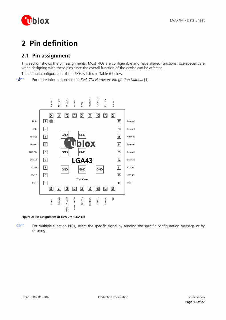
2 Pin definition
2.1 Pin assignment This section shows the pin assignments. Most PIOs are configurable and have shared functions. Use special care when designing with these pins since the overall function of the device can be affected.
The default configuration of the PIOs is listed in Table 6 below.
For more information see the EVA-7M Hardware Integration Manual [1].
Figure 2: Pin assignment of EVA-7M (LGA43)
For multiple function PIOs, select the specific signal by sending the specific configuration message or by e-fusing.
EVA-7M - Data Sheet
UBX-13000581 - R07 Production Information Pin definition
Page 14 of 27
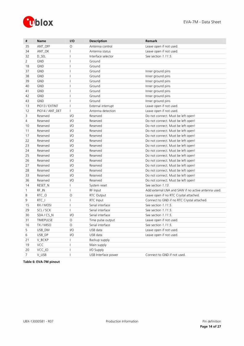
# Name I/O Description Remark
35 ANT_OFF O Antenna control Leave open if not used.
34 ANT_OK I Antenna status Leave open if not used.
32 D_SEL I Interface selector See section 1.11.5.
2 GND I Ground
18 GND I Ground
37 GND I Ground Inner ground pins
38 GND I Ground Inner ground pins
39 GND I Ground Inner ground pins
40 GND I Ground Inner ground pins
41 GND I Ground Inner ground pins
42 GND I Ground Inner ground pins
43 GND I Ground Inner ground pins
13 PIO13 / EXTINT I External interrupt Leave open if not used.
12 PIO14 / ANT_DET I Antenna detection Leave open if not used.
3 Reserved I/O Reserved Do not connect. Must be left open!
4 Reserved I/O Reserved Do not connect. Must be left open!
10 Reserved I/O Reserved Do not connect. Must be left open!
11 Reserved I/O Reserved Do not connect. Must be left open!
17 Reserved I/O Reserved Do not connect. Must be left open!
22 Reserved I/O Reserved Do not connect. Must be left open!
23 Reserved I/O Reserved Do not connect. Must be left open!
24 Reserved I/O Reserved Do not connect. Must be left open!
25 Reserved I/O Reserved Do not connect. Must be left open!
26 Reserved I/O Reserved Do not connect. Must be left open!
27 Reserved I/O Reserved Do not connect. Must be left open!
28 Reserved I/O Reserved Do not connect. Must be left open!
33 Reserved I/O Reserved Do not connect. Must be left open!
36 Reserved I/O Reserved Do not connect. Must be left open!
14 RESET_N I System reset See section 1.13.
1 RF_IN I RF Input Add external LNA and SAW if no active antenna used.
8 RTC_O O RTC Output Leave open if no RTC Crystal attached.
9 RTC_I I RTC Input Connect to GND if no RTC Crystal attached.
15 RX / MOSI I Serial interface See section 1.11.5.
29 SCL / SCK I Serial interface See section 1.11.5.
30 SDA / CS_N I/O Serial interface See section 1.11.5.
31 TIMEPULSE O Time pulse output Leave open if not used.
16 TX / MISO O Serial interface See section 1.11.5.
5 USB_DM I/O USB data Leave open if not used.
6 USB_DP I/O USB data Leave open if not used.
21 V_BCKP I Backup supply
19 VCC I Main supply
20 VCC_IO I I/O Supply
7 V_USB I USB Interface power Connect to GND if not used.
Table 6: EVA-7M pinout
EVA-7M - Data Sheet
UBX-13000581 - R07 Production Information Electrical specification
Page 15 of 27
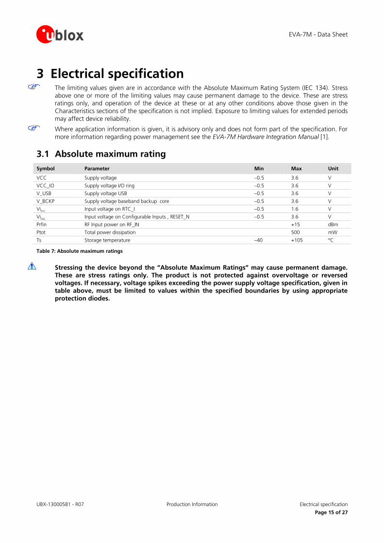
3 Electrical specification The limiting values given are in accordance with the Absolute Maximum Rating System (IEC 134). Stress
above one or more of the limiting values may cause permanent damage to the device. These are stress ratings only, and operation of the device at these or at any other conditions above those given in the Characteristics sections of the specification is not implied. Exposure to limiting values for extended periods may affect device reliability.
Where application information is given, it is advisory only and does not form part of the specification. For more information regarding power management see the EVA-7M Hardware Integration Manual [1].
3.1 Absolute maximum rating Symbol Parameter Min Max Unit
VCC Supply voltage –0.5 3.6 V
VCC_IO Supply voltage I/O ring –0.5 3.6 V
V_USB Supply voltage USB –0.5 3.6 V
V_BCKP Supply voltage baseband backup core –0.5 3.6 V
ViRTC Input voltage on RTC_I –0.5 1.6 V
ViDIG Input voltage on Configurable Inputs , RESET_N –0.5 3.6 V
Prfin RF Input power on RF_IN +15 dBm
Ptot Total power dissipation 500 mW
Ts Storage temperature –40 +105 °C
Table 7: Absolute maximum ratings
Stressing the device beyond the “Absolute Maximum Ratings” may cause permanent damage. These are stress ratings only. The product is not protected against overvoltage or reversed voltages. If necessary, voltage spikes exceeding the power supply voltage specification, given in table above, must be limited to values within the specified boundaries by using appropriate protection diodes.
EVA-7M - Data Sheet
UBX-13000581 - R07 Production Information Electrical specification
Page 16 of 27
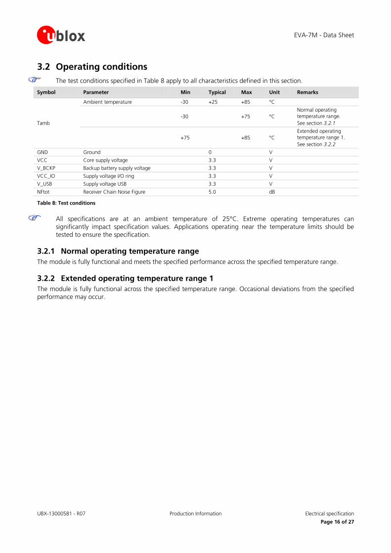
3.2 Operating conditions The test conditions specified in Table 8 apply to all characteristics defined in this section.
Symbol Parameter Min Typical Max Unit Remarks
Tamb
Ambient temperature -30 +25 +85 °C
-30 +75 °C Normal operating temperature range. See section 3.2.1
+75 +85 °C Extended operating temperature range 1. See section 3.2.2
GND Ground 0 V
VCC Core supply voltage 3.3 V
V_BCKP Backup battery supply voltage 3.3 V
VCC_IO Supply voltage I/O ring 3.3 V
V_USB Supply voltage USB 3.3 V
NFtot Receiver Chain Noise Figure 5.0 dB
Table 8: Test conditions
All specifications are at an ambient temperature of 25°C. Extreme operating temperatures can significantly impact specification values. Applications operating near the temperature limits should be tested to ensure the specification.
3.2.1 Normal operating temperature range The module is fully functional and meets the specified performance across the specified temperature range.
3.2.2 Extended operating temperature range 1 The module is fully functional across the specified temperature range. Occasional deviations from the specified performance may occur.
EVA-7M - Data Sheet
UBX-13000581 - R07 Production Information Electrical specification
Page 17 of 27
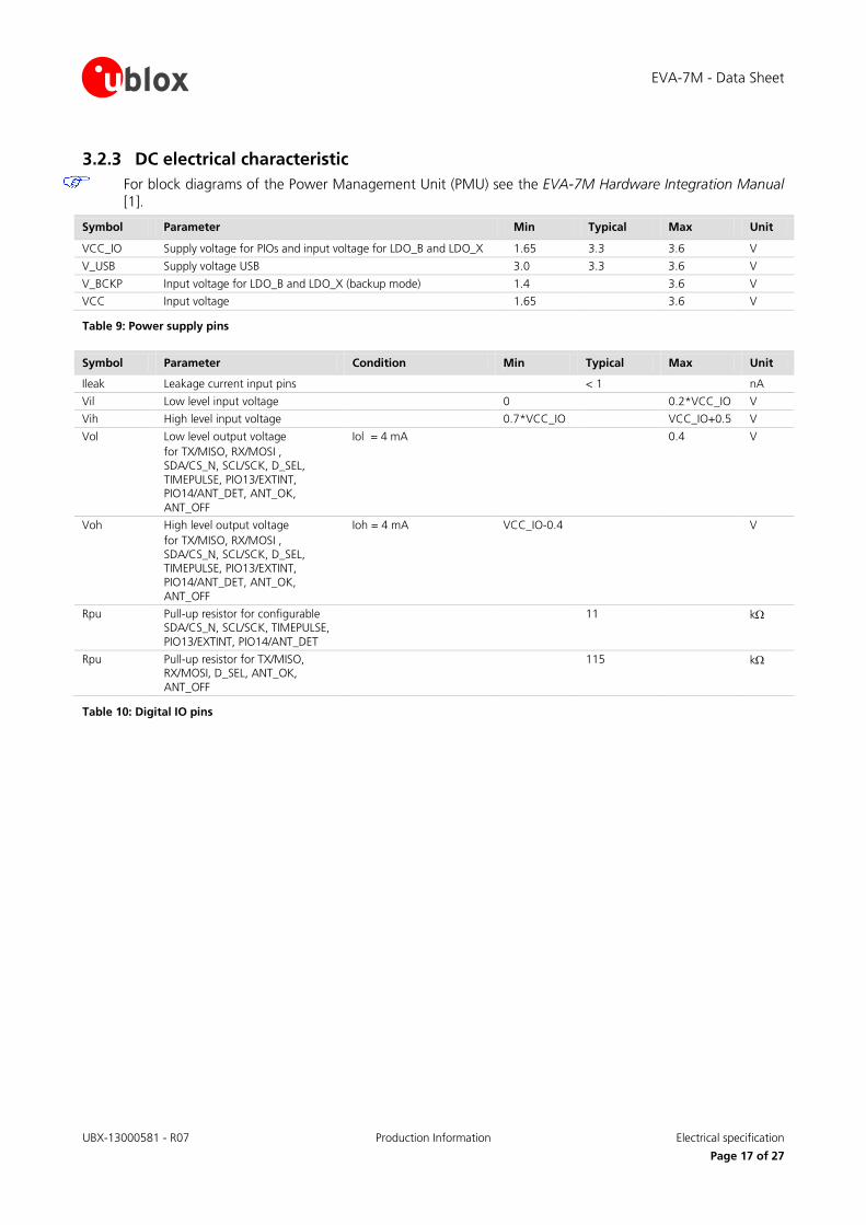
3.2.3 DC electrical characteristic For block diagrams of the Power Management Unit (PMU) see the EVA-7M Hardware Integration Manual
[1].
Symbol Parameter Min Typical Max Unit
VCC_IO Supply voltage for PIOs and input voltage for LDO_B and LDO_X 1.65 3.3 3.6 V
V_USB Supply voltage USB 3.0 3.3 3.6 V
V_BCKP Input voltage for LDO_B and LDO_X (backup mode) 1.4 3.6 V
VCC Input voltage 1.65 3.6 V
Table 9: Power supply pins
Symbol Parameter Condition Min Typical Max Unit
Ileak Leakage current input pins < 1 nA
Vil Low level input voltage 0 0.2*VCC_IO V
Vih High level input voltage 0.7*VCC_IO VCC_IO+0.5 V
Vol Low level output voltage for TX/MISO, RX/MOSI , SDA/CS_N, SCL/SCK, D_SEL, TIMEPULSE, PIO13/EXTINT, PIO14/ANT_DET, ANT_OK, ANT_OFF
Iol = 4 mA 0.4 V
Voh High level output voltage for TX/MISO, RX/MOSI , SDA/CS_N, SCL/SCK, D_SEL, TIMEPULSE, PIO13/EXTINT, PIO14/ANT_DET, ANT_OK, ANT_OFF
Ioh = 4 mA VCC_IO-0.4 V
Rpu Pull-up resistor for configurable SDA/CS_N, SCL/SCK, TIMEPULSE, PIO13/EXTINT, PIO14/ANT_DET
11 kΩ
Rpu Pull-up resistor for TX/MISO, RX/MOSI, D_SEL, ANT_OK, ANT_OFF
115 kΩ
Table 10: Digital IO pins
EVA-7M - Data Sheet
UBX-13000581 - R07 Production Information Electrical specification
Page 18 of 27
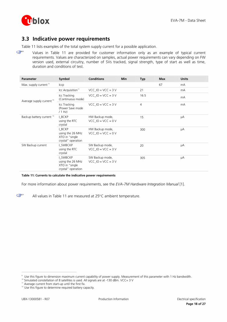
3.3 Indicative power requirements Table 11 lists examples of the total system supply current for a possible application.
Values in Table 11 are provided for customer information only as an example of typical current requirements. Values are characterized on samples, actual power requirements can vary depending on FW version used, external circuitry, number of SVs tracked, signal strength, type of start as well as time, duration and conditions of test.
Parameter Symbol Conditions Min Typ Max Units
Max. supply current 9 Iccp 67 mA
Average supply current 10
Icc Acquisition11 VCC_IO = VCC = 3 V 21 mA
Icc Tracking (Continuous mode)
VCC_IO = VCC = 3 V
16.5 mA
Icc Tracking (Power Save mode / 1 Hz)
VCC_IO = VCC = 3 V 4 mA
Backup battery current 12 I_BCKP using the RTC crystal
HW Backup mode, VCC_IO = VCC = 0 V
15 µA
I_BCKP using the 26 MHz XTO in “single crystal” operation
HW Backup mode, VCC_IO = VCC = 0 V
300 µA
SW Backup current I_SWBCKP using the RTC crystal
SW Backup mode, VCC_IO = VCC = 3 V
20 µA
I_SWBCKP using the 26 MHz XTO in “single crystal” operation
SW Backup mode, VCC_IO = VCC = 3 V
305 µA
Table 11: Currents to calculate the indicative power requirements
For more information about power requirements, see the EVA-7M Hardware Integration Manual [1].
All values in Table 11 are measured at 25°C ambient temperature.
9 Use this figure to dimension maximum current capability of power supply. Measurement of this parameter with 1 Hz bandwidth. 10 Simulated constellation of 8 satellites is used. All signals are at -130 dBm. VCC= 3 V 11 Average current from start-up until the first fix. 12 Use this figure to determine required battery capacity.
EVA-7M - Data Sheet
UBX-13000581 - R07 Production Information Electrical specification
Page 19 of 27
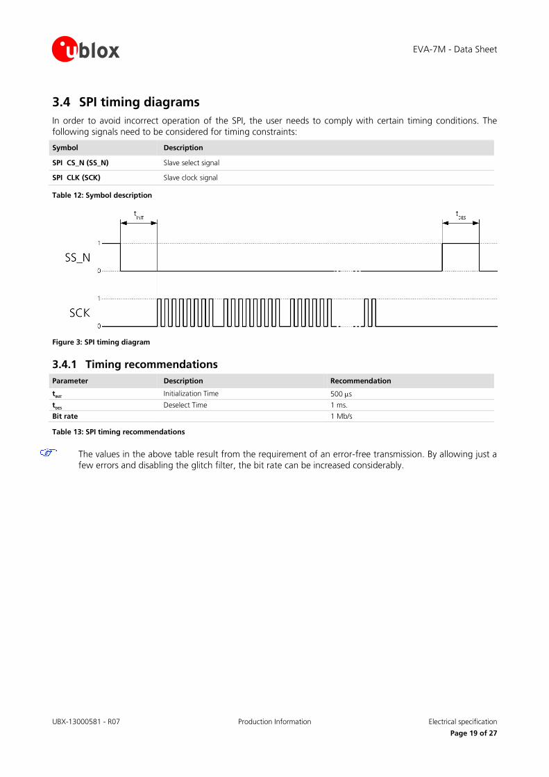
3.4 SPI timing diagrams In order to avoid incorrect operation of the SPI, the user needs to comply with certain timing conditions. The following signals need to be considered for timing constraints:
Symbol Description
SPI CS_N (SS_N) Slave select signal
SPI CLK (SCK) Slave clock signal
Table 12: Symbol description
Figure 3: SPI timing diagram
3.4.1 Timing recommendations Parameter Description Recommendation
tINIT Initialization Time 500 µs
tDES Deselect Time 1 ms.
Bit rate 1 Mb/s
Table 13: SPI timing recommendations
The values in the above table result from the requirement of an error-free transmission. By allowing just a few errors and disabling the glitch filter, the bit rate can be increased considerably.
EVA-7M - Data Sheet
UBX-13000581 - R07 Production Information Mechanical specification
Page 20 of 27
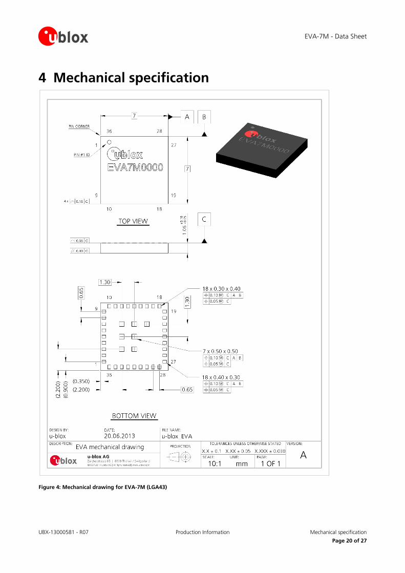
4 Mechanical specification
Figure 4: Mechanical drawing for EVA-7M (LGA43)
EVA-7M - Data Sheet
UBX-13000581 - R07 Production Information Reliability tests and approvals
Page 21 of 27
5 Reliability tests and approvals
5.1 Reliability tests Qualification requirements according JEDEC standards JESD47 "Stress-Test-Driven Qualification of Integrated Circuits".
5.2 Approvals
Products marked with this lead-free symbol on the product label comply with the "Directive 2002/95/EC of the European Parliament and the Council on the Restriction of Use of certain Hazardous Substances in Electrical and Electronic Equipment" (RoHS).
EVA-7M is RoHS compliant and green (no halogens).
EVA-7M - Data Sheet
UBX-13000581 - R07 Production Information Product handling
Page 22 of 27
6 Product handling
6.1 Packaging EVA-7M positioning modules are delivered as hermetically sealed, reeled tapes in order to enable efficient production, production lot set-up and tear-down. For more information about packaging, see the u-blox Package Information Guide [3].
6.1.1 Reels EVA-7M modules are deliverable in quantities of 500 pcs on a reel. EVA-7M receivers are shipped on Reel Type D, as described in the u-blox Package Information Guide [3].
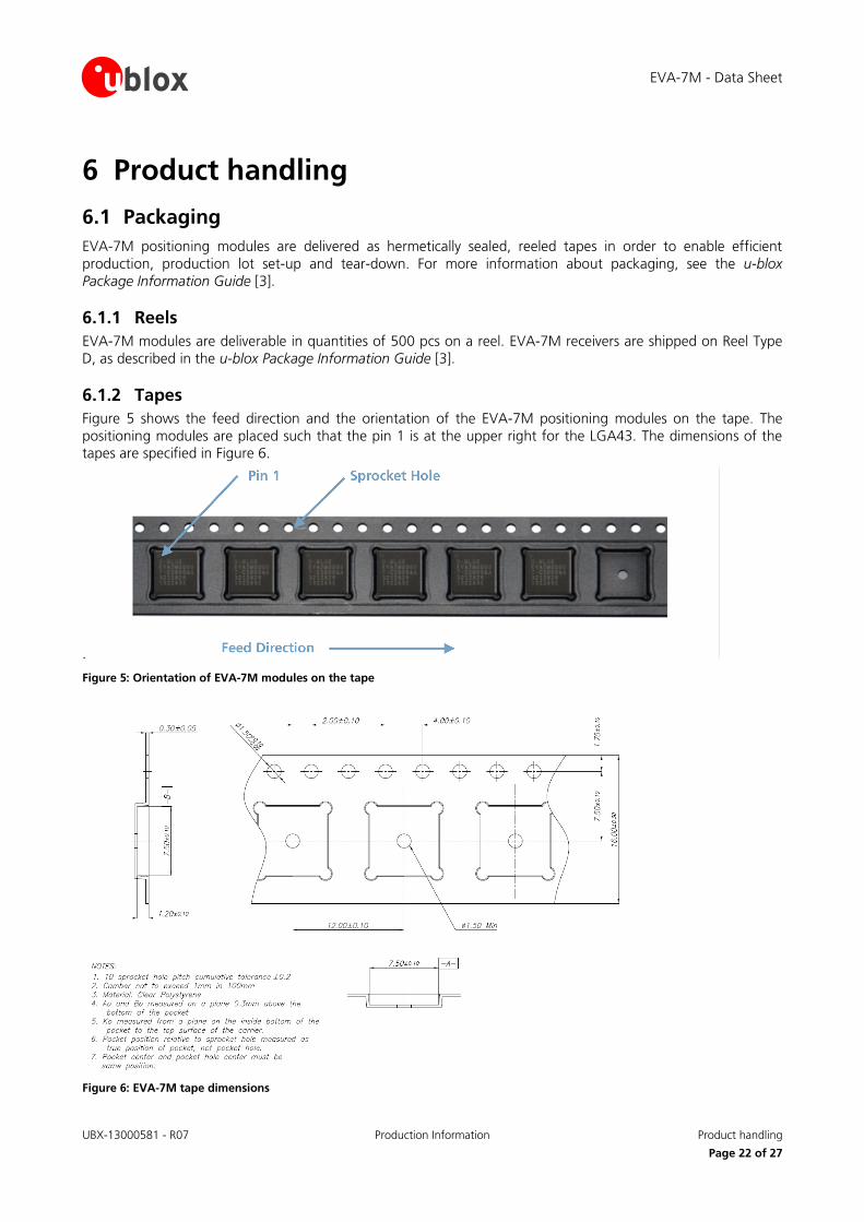
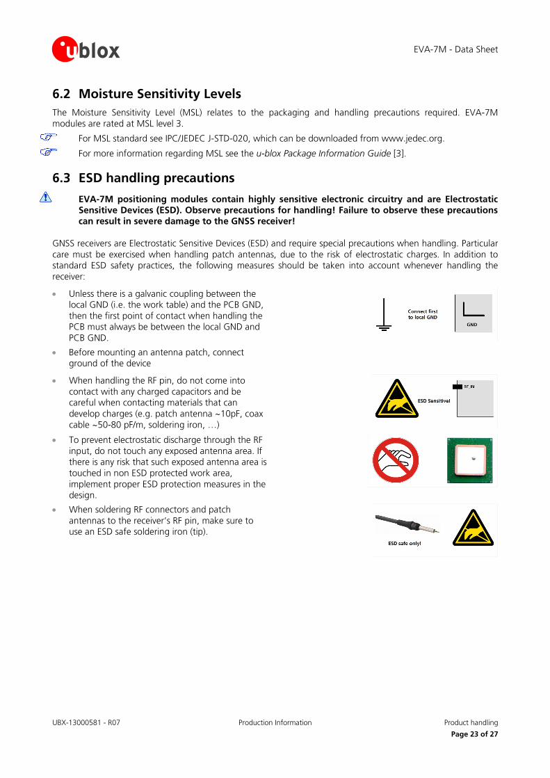
6.1.2 Tapes Figure 5 shows the feed direction and the orientation of the EVA-7M positioning modules on the tape. The positioning modules are placed such that the pin 1 is at the upper right for the LGA43. The dimensions of the tapes are specified in Figure 6.
.
Figure 5: Orientation of EVA-7M modules on the tape
Figure 6: EVA-7M tape dimensions
EVA-7M - Data Sheet
UBX-13000581 - R07 Production Information Product handling
Page 23 of 27
6.2 Moisture Sensitivity Levels The Moisture Sensitivity Level (MSL) relates to the packaging and handling precautions required. EVA-7M modules are rated at MSL level 3.
For MSL standard see IPC/JEDEC J-STD-020, which can be downloaded from www.jedec.org.
For more information regarding MSL see the u-blox Package Information Guide [3].
6.3 ESD handling precautions
EVA-7M positioning modules contain highly sensitive electronic circuitry and are Electrostatic Sensitive Devices (ESD). Observe precautions for handling! Failure to observe these precautions can result in severe damage to the GNSS receiver!
GNSS receivers are Electrostatic Sensitive Devices (ESD) and require special precautions when handling. Particular care must be exercised when handling patch antennas, due to the risk of electrostatic charges. In addition to standard ESD safety practices, the following measures should be taken into account whenever handling the receiver:
• Unless there is a galvanic coupling between the local GND (i.e. the work table) and the PCB GND, then the first point of contact when handling the PCB must always be between the local GND and PCB GND.
• Before mounting an antenna patch, connect ground of the device
• When handling the RF pin, do not come into contact with any charged capacitors and be careful when contacting materials that can develop charges (e.g. patch antenna ~10pF, coax cable ~50-80 pF/m, soldering iron, …)
• To prevent electrostatic discharge through the RF input, do not touch any exposed antenna area. If there is any risk that such exposed antenna area is touched in non ESD protected work area, implement proper ESD protection measures in the design.
• When soldering RF connectors and patch antennas to the receiver’s RF pin, make sure to use an ESD safe soldering iron (tip).
EVA-7M - Data Sheet
UBX-13000581 - R07 Production Information Default messages
Page 24 of 27
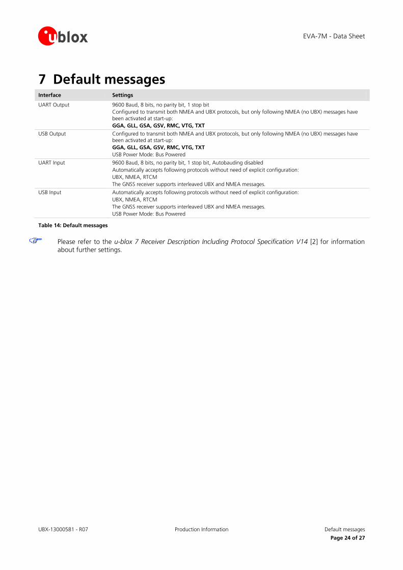
7 Default messages Interface Settings
UART Output
9600 Baud, 8 bits, no parity bit, 1 stop bit Configured to transmit both NMEA and UBX protocols, but only following NMEA (no UBX) messages have been activated at start-up: GGA, GLL, GSA, GSV, RMC, VTG, TXT
USB Output Configured to transmit both NMEA and UBX protocols, but only following NMEA (no UBX) messages have been activated at start-up: GGA, GLL, GSA, GSV, RMC, VTG, TXT USB Power Mode: Bus Powered
UART Input 9600 Baud, 8 bits, no parity bit, 1 stop bit, Autobauding disabled Automatically accepts following protocols without need of explicit configuration: UBX, NMEA, RTCM The GNSS receiver supports interleaved UBX and NMEA messages.
USB Input Automatically accepts following protocols without need of explicit configuration: UBX, NMEA, RTCM The GNSS receiver supports interleaved UBX and NMEA messages. USB Power Mode: Bus Powered
Table 14: Default messages
Please refer to the u-blox 7 Receiver Description Including Protocol Specification V14 [2] for information about further settings.
EVA-7M - Data Sheet
UBX-13000581 - R07 Production Information Labeling and ordering information
Page 25 of 27
8 Labeling and ordering information
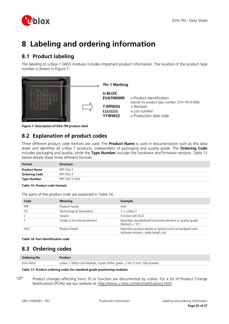
8.1 Product labeling The labeling of u-blox 7 GNSS modules includes important product information. The location of the product type number is shown in Figure 7.
Figure 7: Description of EVA-7M product label
8.2 Explanation of product codes Three different product code formats are used. The Product Name is used in documentation such as this data sheet and identifies all u-blox 7 products, independent of packaging and quality grade. The Ordering Code includes packaging and quality, while the Type Number includes the hardware and firmware versions. Table 15 below details these three different formats:
Format Structure
Product Name PPP-TGV-T
Ordering Code PPP-TGV-T
Type Number PPP-TGV-T-XXX
Table 15: Product code formats
The parts of the product code are explained in Table 16.
Code Meaning Example
PPP Product Family EVA
TG Technology & Generation 7 = u-blox 7
V Variant Function set (A-Z)
T Grade or functional element Describes standardized functional element or quality grade (Default = “0”)
XXX Product Detail Describes product details or options such as hardware and software revision, cable length, etc.
Table 16: Part identification code
8.3 Ordering codes Ordering No. Product
EVA-7M-0 u-blox 7 GNSS LGA Module, crystal, ROM, green, 7.0x7.0 mm, 500 pcs/reel
Table 17: Product ordering codes for standard grade positioning modules
Product changes affecting form, fit or function are documented by u-blox. For a list of Product Change Notifications (PCNs) see our website at: http://www.u-blox.com/en/notifications.html.
U-BLOX EVA7M0000 = Product identification
(stands for product type number: EVA-7M-0-000) T-Rff00SS = Revision LLLLLLLL = Lot number YYWWZZ = Production date code
Pin 1 Marking
EVA-7M - Data Sheet
UBX-13000581 - R07 Production Information Related documents
Page 26 of 27
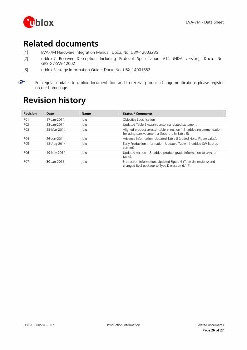
Related documents [1] EVA-7M Hardware Integration Manual, Docu. No. UBX-12003235
[2] u-blox 7 Receiver Description Including Protocol Specification V14 (NDA version), Docu. No. GPS.G7-SW-12002
[3] u-blox Package Information Guide, Docu. No. UBX-14001652
For regular updates to u-blox documentation and to receive product change notifications please register on our homepage.
Revision history
Revision Date Name Status / Comments
R01 17-Jan-2014 julu Objective Specification
R02 23-Jan-2014 julu Updated Table 5 (passive antenna related statement)
R03 25-Mar-2014 julu Aligned product selector table in section 1.3; added recommendation for using passive antenna (footnote in Table 5)
R04 26-Jun-2014 julu Advance Information. Updated Table 8 (added Noise Figure value).
R05 13-Aug-2014 julu Early Production Information. Updated Table 11 (added SW Backup current)
R06 19-Nov-2014 julu Updated section 1.3 (added product grade information to selector table).
R07 30-Jan-2015 julu Production Information. Updated Figure 6 (Tape dimensions) and changed Reel package to Type D (section 6.1.1).
EVA-7M - Data Sheet
UBX-13000581 - R07 Production Information Contact
Page 27 of 27
Contact For complete contact information visit us at www.u-blox.com
u-blox Offices
North, Central and South America
u-blox America, Inc.
Phone: +1 703 483 3180 E-mail: [email protected]
Regional Office West Coast:
Phone: +1 408 573 3640 E-mail: [email protected]
Technical Support:
Phone: +1 703 483 3185 E-mail: [email protected]
Headquarters Europe, Middle East, Africa
u-blox AG
Phone: +41 44 722 74 44 E-mail: [email protected] Support: [email protected]
Asia, Australia, Pacific
u-blox Singapore Pte. Ltd.
Phone: +65 6734 3811 E-mail: [email protected] Support: [email protected]
Regional Office Australia: Phone: +61 2 8448 2016 E-mail: [email protected] Support: [email protected]
Regional Office China (Beijing):
Phone: +86 10 68 133 545 E-mail: [email protected] Support: [email protected]
Regional Office China (Shenzhen):
Phone: +86 755 8627 1083 E-mail: [email protected] Support: [email protected]
Regional Office India:
Phone: +91 959 1302 450 E-mail: [email protected] Support: [email protected]
Regional Office Japan:
Phone: +81 3 5775 3850 E-mail: [email protected] Support: [email protected]
Regional Office Korea:
Phone: +82 2 542 0861 E-mail: [email protected] Support: [email protected]
Regional Office Taiwan:
Phone: +886 2 2657 1090 E-mail: [email protected] Support: [email protected]