Embed Size (px)
Citation preview

TypingRing: A Wearable Ring Platform for Text Input
Shahriar Nirjon, Jeremy Gummeson, Dan Gelb, Kyu-Han KimHewlett-Packard Labs, CA, USA
{nirjon, jeremy.gummeson, dan.gelb, kyu-han.kim}@hp.com
ABSTRACTThis paper presents TypingRing, a wearable ring platformthat enables text input into computers of different forms,such as PCs, smartphones, tablets, or even wearables withtiny screens. The basic idea of TypingRing is to have a userwear a ring on his middle finger and let him type on a sur-face – such as a table, a wall, or his lap. The user types as ifa standard QWERTY keyboard is lying underneath his handbut is invisible to him. By using the embedded sensors Typ-ingRing determines what key is pressed by the user. Further,the platform provides visual feedback to the user and com-municates with the computing device wirelessly. This pa-per describes the hardware and software prototype of Typin-gRing and provides an in-depth evaluation of the platform.Our evaluation shows that TypingRing is capable of detect-ing and sending key events in real-time with an average ac-curacy of 98.67%. In a field study, we let seven users type aparagraph with the ring, and we find that TypingRing yieldsa reasonable typing speed (e.g., 33 − 50 keys per minute)and their typing speed improves over time.
Categories and Subject DescriptorsC.3 [Special-Purpose and Application-Based Systems]: Real-time and embedded systems
General TermsAlgorithm, Design, Experimentation
KeywordsWearable, Typing, Ring
1. INTRODUCTIONAs computing systems evolve, so do their input meth-
ods. With advancements in computing technology, differentforms of text input methods have been proposed and used inpractice. These forms include the standard QWERTY key-boards for PCs, alphanumeric keypads and small keypads inearlier mobile phones, and on-screen soft keyboards in mod-ern smartphones and tablets. Each of these input method-ologies for typing in text has been invented out of the need
for a change as the form factor and the mobility require-ments of these devices have changed. We are now at theforefront of technology where wearable computers, such assmart watches and smart bands, have entered the consumermarket. These devices have even smaller screen sizes andnone of the existing typing methods are viable for these de-vices. A quick fix to this problem has so far been in theform of speech-to-text or shared keypads. However, the coreproblem has still remained unsolved, i.e. there is no typingaccessory that is portable and usable with computers of allform factors and mobility requirements.
To meet this need we have created TypingRing, whichis a wearable keyboard in the form factor of a ring. A userwears the ring on his middle finger and types in text withhis three fingers (the index, the middle and the traditionalring finger) on a surface, such as – a table, his lap, or a wall.The user types and moves his hand as if there is an invisiblestandard keyboard underneath his hand. By moving the handhorizontally and vertically, TypingRing identifies one regionto another on the imaginary keyboard. Further, by pressingone of his three fingers, the user types in the key. By usingthe embedded sensors surrounding the ring, TypingRing de-termines what key is pressed by the user completely insidethe ring and then sends the key event to a remote computerover the Bluetooth LE network. TypingRing implements thestandard BLE keyboard protocol so that it can be used withcommercially available computing devices, such as – PCs,smartphones, tablets, or even wearables with tiny screensthat support an external BLE keyboard. A piece of softwarerunning on the computing device intercepts the key eventsand provides a visual feedback to the user by highlighting akey or a portion of a custom on-screen keyboard, as the usermoves his hand on the surface and types in keys.
Several salient features when combined together makeTypingRing unique of its kind. First, TypingRing being awearable device, is mobile and portable. The ring comeshandy in scenarios where a quick and on-the-go text inputis needed or scenarios when an alternative input method isnot convenient, e.g. devices with tiny screens. Second, Typ-ingRing is fast and highly accurate in detecting keys, and itperforms all its computations inside the ring – without re-quiring any computational support from a more capable de-
1

vice. Third, TypingRing is multi-platform. Because of itsadoption of standard BLE keyboard protocol, TypingRing isusable with any computing device that supports an externalBLE keyboard. Fourth, typing with TypingRing is intuitiveand it is easy to learn. TypingRing breaks down the taskof typing on a standard keyboard into two intuitive tasks, i.e.moving a hand on a surface and then pressing a finger, whichrequire little or no practice to get started with. Fifth, Typin-gRing is flexible and extensible. It is not tied to Englishalphabet or any specific keyboard layout. By changing themapping between a position and a key, TypingRing is usablewith keyboards of different layouts and dimensions.
TypingRing brings both engineering and computationalchallenges in front of us. The hardware architecture of Typ-ingRing is designed to obtain the relative movements of thefinger, and horizontal and vertical motions of the hand ona surface, so that thus-obtained data can be used to inferthe position of the hand and typing gestures from just a sin-gle finger. To realize this, we embed a tiny microcontroller,an accelerometer, multiple line sensors, an optical displace-ment sensor, and a BLE chip on the perimeter of a circularring platform. These sensors are read by a software run-ning inside the ring, which detects and classifies typing ges-tures using an offline trained Hidden Markov Model (HMM)classifier. As an additional feature in TypingRing, we haveimplemented a simple Naïve Bayesian classifier to infer 3Dgestures, such as - pitch, roll, and yaw, and map them tocommonly used keys on a keyboard to offer shortcut keys tothe user.
We have created a prototype of TypingRing using off-the-shelf sensors and an open source miniature hardwareplatform called TinyDuino [11]. In order to, tune variousparameters of the system and train the typing and gestureclassifiers, we perform an empirical study involving 18 userswho uses the ring to type in letters, words, lines, and ges-tures while we store all the raw sensor readings. Basedon this empirical data, we measure execution time, energyconsumption, and the accuracy of typing and gesture clas-sifiers. Our empirical evaluation shows that TypingRing iscapable of detecting and generating key events in real-timewith an average accuracy of 98.67%. Finally, we performa field study, in which, we let seven users type a paragraphwith TypingRing and we find that TypingRing yields a typ-ing speed of 0.55 − 0.81 keys per second, and their typingspeed improves over time.
The contributions of this paper are the following –• We introduce TypingRing, which is a wearable, portable
accessory device that allows a user to input text into mo-bile and non-mobile computers of different forms.
• We describe a Hidden Markov Model (HMM) based typ-ing gesture recognizer that uses acceleration, optical dis-placement and proximity sensors to infer the typing fin-ger in real-time and with an average accuracy of 98.67%.
• We perform a field study by letting seven end users type a
paragraph with TypingRing and we find that TypingRingyields a typing speed of 33 − 50 keys per minute, andtheir typing speed improves over time.
2. USING TYPING RINGThis section describes the working principle of the Typ-
ingRing along with some potential use cases.
2.1 Working PrincipleTypingRing is worn on the middle finger of a user. As
the user rests his ring on a horizontal surface, three consecu-tive keys on the on-screen keyboard of the computing deviceare highlighted. By using embedded sensors surroundingthe perimeter of the ring, the TypingRing detects typing ges-tures made by the user’s three fingers – middle, index, andtraditional ring fingers. To highlight a different set of keys,the user simply drags the ring up, down, left or right on thesurface. As long as the user is seeking a key or typing itin, visual feedback is provided to him on the screen of thecomputing device.
TypingRing assumes that the standard keyboard layout isdivided into multiple zones. A zone is defined as a sequenceof consecutive 3 keys on the same row on a keyboard lay-out. With this definition of a zone, the task of locating a keybecomes a two-step problem: first, to identify the zone ofthe intended key, and second, to identify the key within thatzone.
By moving the ring horizontally and vertically on a sur-face, a user moves from one zone to another. The user isgiven visual feedback by either highlighting the 3 keys on thezone on a soft-keyboard or just showing 3 keys on the screenwhen the computing device has a limited screen space. Oncea zone is selected, each of the three fingers is associated withone of the 3 keys in that zone. To type in a specific key, theuser makes a typing gesture using the corresponding finger.The ring detects the finger and sends the key associated withit to the computing device over the wireless channel.
(a) 3-Letter Zones
f gh
(b) Typing Ring
Figure 1: Working principle of TypingRing.
Example. In Figure 1(a), we show sixteen zones on anAndroid keyboard layout marked with dotted rectangles andthe selected zone fgh with a solid rectangle. Only one zoneis allowed to be active at a time. A large key (e.g. the spacebar) may be a part of multiple zones and the last zone on a
2

row may not have all three keys. To type in a letter, e.g. W,the user at first moves his ring up and left to select the QWE
zone, and then makes a typing gesture with his middle fingerto input the key.
2.2 Usage ScenariosTypingRing may be used with a variety of computing
devices that support standard external wireless keyboards.The list includes desktops, laptops, tablets, smartphones, andsmart watches. However, below we list several compellingusage scenarios, where TypingRing is a more convenientchoice than other input methods (e.g., on-screen keyboard).• Devices with Tiny Screens. Some computing devices,
such as smart watches and smart wristbands, have verysmall sized screens where a full scale touch enabled key-board is not an option. TypingRing can be used withthese devices as it physically separates the actual typingaction from the visual feedback, and hence, the keyboardlayout can be scaled down enough to just to show a tinykeyboard with highlighted keys, or a single row of keys,or just the 3 keys on a selected zone.• Saving Screen Space on a Mobile Display. Typical on-
screen soft keyboards on a mobile device block out morethan 40% of the display. This is annoying to the useras the blocked out area may contain information that theuser needs to see while typing in his inputs. With Typ-ingRing, the size of the blocked area is reduced up to 10times, and hence, the freed space can be utilized by theapplication to improve user experience.• Quick and On-the-Go Typing. In some situations, e.g.
self checking-in at an airport kiosk, making transactionsat ATMs, or inputting pass codes into locks, we wantto input text quickly and on-the-go. Health consciouspeople who want to avoid touching the keypads on thesepublic devices might want to use their personal mobiledevice for input. The TypingRing being a wearable de-vice, is more convenient in these scenarios than pullingout a mobile phone from the pocket and interacting withthe display.
3. SYSTEM OVERVIEWThis section overviews the system architecture of Typin-
gRing. We defer the algorithms and implementation detailsto subsequent sections.
3.1 The Hardware ArchitectureTypingRing hardware platform is a redesign of conven-
tional rings that has embedded sensors surrounding its perime-ter and a tiny micro-controller unit having wireless data com-munication capability. The platform enables continuous sens-ing of user’s hand and finger movements and processes thesensing data on-board to generate the key events. Figure 2is a schematic of the TypingRing– showing the componentsand their placements on the ring.
MCU + Battery
Left FingerProximity
Right FingerProximity
DisplacementΔX, ΔY
AccelerometerBluetooth LE
Figure 2: Hardware architecture of TypingRing.
• Microcontroller. The top of the ring, where usually ajewel is placed, consists of three boards stacked on topof each other. One of these is a micro-controller unit(MCU) that operates all the components, processes sens-ing data to determine key events, and transmits the keyinformation. The MCU is powered by a thin film battery.
• Accelerometer. A 3-axis accelerometer is placed on topthe ring, and it primarily detects the movement of themiddle finger and helps detect other fingers. This sensoris kept always on to detect the presence of motion andturn on and off other sensors as needed.
• Proximity Sensors. Two proximity sensors are placedon the sides of the ring facing the two fingers which arenext to the middle finger. Their placement allows thering to measure the proximity between the middle fingerand the two fingers next to it. This is used to detect whichfinger is used for typing.
• Displacement Sensor. An optical displacement sensor,like the ones used in an optical mouse, is placed under-neath the ring to detect the X and Y displacements ofthe ring. This is used to detect when the user changes histyping zone.
• Bluetooth LE. A Bluetooth LE chip is connected on topof the ring, which is used by the MCU to send key eventswirelessly to the computing device using the standardBLE keyboard protocol.
3.2 The Firmware ArchitectureThe TypingRing determines the key events completely
inside the ring without relying on the computing device forany computational help. This makes it a self-sufficient in-put accessory just like a regular Bluetooth LE keyboard. Analternative to this would be to transmit raw or partially pro-cessed sensing data and let the device determine the keyevents. This, however, would require higher bandwidth com-munication, increase the data transmission cost, and makethe ring a non-standard input accessory. The firmware run-ning inside the TypingRing is responsible for controlling thesensors, determining the key strokes, and generating andsending key events to the computing device.
Figure 3 shows the architecture of the firmware. Figure3 shows the architecture of the firmware. As shown in thefigure, the firmware is composed of three layers: sensing,recognition, and communication.
3
BLECommunication
Key Event Generator
AccelerometerSe
nsin
g La
yer
ControllerUnit
KeyMap
GestureMap
Proximity
Key StrokeRecognizer
GestureRecognizer
OpticalK
ey a
nd G
estu
re
Rec
ogni
tion
Map
ping
and
C
omm
unic
atio
n
[high motion, ring lifted]
[low motion, ring down]
zone/position pitch/yaw/roll
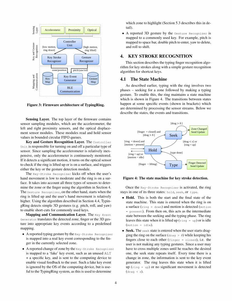
Figure 3: Firmware architecture of TypingRing.
Sensing Layer. The top layer of the firmware containssensor sampling modules, which are the accelerometer, theleft and right proximity sensors, and the optical displace-ment sensor modules. These modules read and hold sensorvalues in bounded circular FIFO queues.
Key and Gesture Recognition Layer. The Controller
Unit is responsible for turning on and off a particular type ofsensor. Since sampling the accelerometer is relatively inex-pensive, only the accelerometer is continuously monitored.If it detects a significant motion, it turns on the optical sensorto check if the ring is lifted up or is on a surface, and triggerseither the key or the gesture detection module.
The Key-Stroke Recognizer kicks off when the user’shand movement is low to moderate and the ring is on a sur-face. It takes into account all three types of sensors to deter-mine the zone or the finger using the algorithm in Section 4.The Gesture Recognizer, on the other hand, starts when thering is lifted up and the user’s hand movement is relativelyhigher. Using the algorithm described in Section 4.4, Typin-gRing detects simple 3D gestures (e.g. pitch, roll, and yaw)to enable short-cuts for commonly used keys.
Mapping and Communication Layer. The Key Event
Generator translates the detected zone, finger or the 3D ges-ture into appropriate key events according to a predefinedmapping.• A reported typing gesture by the Key-Stroke Recognizer
is mapped into a real key event corresponding to the fin-ger in the currently selected zone.
• A reported change of zone by the Key-Stroke Recognizer
is mapped to a ‘fake’ key event, such as an unused ALT+ a specific key, and is sent to the computing device toenable visual feedback to the user. Such a fake key eventis ignored by the OS of the computing device, but is use-ful to the TypingRing system, as this is used to determine
which zone to highlight (Section 5.3 describes this in de-tail).
• A reported 3D gesture by the Gesture Recognizer ismapped to a commonly used key. For example, pitch ismapped to space bar, double pitch to enter, yaw to delete,and roll to shift.
4. KEY STROKE RECOGNITIONThis section describes the typing finger recognition algo-
rithm for key strokes along with a simple gesture recognitionalgorithm for shortcut keys.
4.1 The State MachineAs described earlier, typing with the ring involves two
phases – seeking for a zone followed by making a typinggesture. To enable this, the ring maintains a state machinewhich is shown in Figure 4. The transitions between stateshappen at some specific events (shown in brackets) whichare determined by processing the sensor streams. Below wedescribe the states, the events and transitions.
Seek
Type
Hold
[drag ϵ] or[ring = up]
[finger = lifting]
[type done]
Zone ChangedSend Update
Finger DetectedSend Update
[finger = closed] and [drag δ]
[ring = up] or [motion = idle]
[ring = down] and[motion = present]
[drag δ]
Figure 4: The state machine for key stroke detection.
Once the Key-Stroke Recognizer is activated, the ringstays in one of its three states: hold, seek, or type.• Hold. This is both the start and the final state of the
state machine. This state is entered when the ring is ona surface (ring = down) and motion is detected (motion= present). From then on, this acts as the intermediatestate between the seeking and the typing phase. The ringleaves this state when it is lifted up (ring = up) or is idle(motion = idle).
• Seek. The seek state is entered when the user starts drag-ging the ring on the surface (drag > δ) while keeping hisfingers close to each other (finger = closed), i.e. theuser is not making any typing gestures. Since a user mayhave to cross multiple zones until he reaches the desiredone, the seek state repeats itself. Every time there is achange in zone, the information is sent to the key eventgenerator. The ring leaves this state when it is liftedup (ring = up) or no significant movement is detected(drag < ε).
4

• Type. The type state is entered when the user lifts upone or both of his fingers (finger = lifting) indicatingan intention to type. This state runs the typing gesturedetection algorithm (Section 4.3) to determine a validtyping gesture and the finger used, and then goes backto the hold state. In case of a valid gesture, it sends thedetected finger to the key event generator.
4.2 Detecting Sensor EventsAll the state transitions in the state machine depend on
the values of four types of event variables: ring, motion,drag, and finger.• Drag Events. The drag event relates to the dragging of
the ring on a surface. These events are triggered when-ever the displacement of the ring over a period crossesa certain threshold. A large drag results in a change ofzone whereas the ring leaves the seek state when there isno significant drag. The value of a drag is calculatedfrom the optical displacement sensor’s readings. Theoptical sensor periodically sends updates on X- and Y-displacements of the ring as a vector, ∆d = (∆x,∆y).These values are too noisy and are hardware accelerated.To compute a drag, ∆d is first passed through a movingaverage filter and then integrated continuously. Transi-tion from one zone to another happens when the inte-grated value exceeds an empirically obtained thresholdδd. Equations 1 and 2 show the filtering and drag com-putation steps.
∆d = α ∆dk + (1− α) ∆dk−1 (1)
drag =
∣∣∣∣ ∫ ∆ddt
∣∣∣∣ (2)
• Finger Events. The finger events happen whenever theuser lifts up one of his fingers or presses down both of hisfingers. These events are determined by two identicaldetectors, one for each finger. Each of these detectorsaccumulate proximity values, {pk} over a period of τpand compute the range. The range is compared to twoempirically obtained thresholds δp and εp to detect fingerlifting and pressing events.
range = maxt−τp≤k≤t
{pk} − mint−τp≤k≤t
{pk} (3)
• Motion Events. The presence or absence of motion isdetermined from the 3-axis accelerometer sensor read-ings (ax, ay, az). The ring keeps track of running vari-
ances of the magnitude of acceleration√a2x + a2y + a2z
over a period τa, and based on a threshold, εa, it deter-mines the presence or absence of motion.• Ring Events. The ring events, i.e. whether or not the
bottom of the ring is touching the surface, are read di-rectly from the optical sensor. The optical sensor has abuilt-in lift detector, which is programmed to detect upto 5 mm lifting.
4.3 Detecting the Typing FingerA naive algorithm to detect the typing finger is to use
thresholds to detect finger events similar to Section 4.2 andthereby identify the finger. However, we empirically foundthat such an algorithm does not work in practical cases andresults in false positives (multiple detections of one or morefingers), false negatives (no detection), and does not provideany confidence on the inference. By employing conservativethresholds false positives may be eliminated, but this inducesdelays in typing gesture detection and frustrates the user asunlike zone seeking there is no visual feedback on how muchadditional effort is needed to exert to type in the key.
In order to enable a robust and accurate finger detection,we leverage an observation that – each finger’s movementhas an effect on the accelerometer readings obtained fromthe middle finger – either directly (for the middle finger) orindirectly (for the other two). With this observation, we de-sign an algorithm that takes both the proximity sensors andthe accelerometer into account. Hence, the problem of typ-ing finger detection is stated as – given periodic proximityand accelerometer sensor readings over an interval, whatis the probability of making a typing gesture with one ofthe three fingers?. If the highest probability for a finger isgreater than a threshold, the finger is reported by the algo-rithm.
Because the algorithm runs inside the ring, the solutionhas to meet some additional requirements. The algorithmneeds to be simple enough for implementation inside thering’s microcontroller, and also has to be fast, accurate, androbust. To achieve this, we use a N -state Hidden MarkovModel (HMM). This satisfies our goals as HMMs are knownto be robust classifiers for time series signals [25] and theyprovide a confidence value of the solution (i.e. a probabil-ity for each class), and a trained HMM is compact enough tostore inside the ring and is fast enough to obtain the probabil-ities in real time. The steps of the algorithm are as follows:• Quantization. The left and right proximity sensor val-
ues, pLi and pRi , and the accelerometer reading ai, arefirst quantized using Q′ and Q′′ functions, respectively.
Q′(pi) = argmin1≤k≤L
∣∣∣∣q′k − pi∣∣∣∣ (4)
Q′′(ai) = argmin1≤k≤L
∣∣∣∣q′′k − V (||ai||)∣∣∣∣ (5)
where, V (||ai||) is the variance in acceleration over asecond, L is the number of quantization levels, and q′kand q′′k are the quantization levels for proximity and ac-celeromoter sensors, respectively. To limit the numberof possible states in the HMM, we use L = 3 level quan-tization, and the levels correspond to the quartiles of theempirical data.
• Encoding. At every sampling interval, the quantizedvalues from the 3 sensor streams produce a 3-tuple, (ρli, ρ
ri , αi),
1 ≤ ρli, ρri , αi ≤ L. Considering all possible combi-
5

nations and 3-level quantization, there can be at mostL3 = 27 different tuples. Each of these tuples is con-sidered as an observed event (called an emmision) in theHMM, resulting in a set of possible emissions, {Yi},1 ≤ i ≤ 27, at each state of HMM.• HMM Classification. Assuming we have a precom-
puted HMM corresponding to sensor data obtained bytyping with a specific finger, this step computes the like-lihood of a given sequence of emissions, y = (y1, ..., yT )being generated by the model. The length of the se-quence T depends on the sampling frequency fs and theduration of a typing event W . In TypingRing, we use asliding window of W = 1 second (with 50% overlap)to capture a typing event. This bounds the value of T todW/fse. Using Viterbi [14] algorithm, we compute themaximum likelihood of y given the precomputed HMM– having a state space S, initial probabilites of each stateπi, 1 < lei ≤ |S|, and transition probabilities ui,j oftransitioning from state i to j – as follows:
v(1, i) = p(y1|i). πi (6)v(t, i) = p(yt|i).max
s∈S(us,i. v(t− 1, s)) (7)
where, v(t, i) is the probability that the most probablestate sequence that could emit y ends in state i. Now, toobtain the maximum likelihood of our HMM to generatey, we apply the following:
vML = max1≤i≤|S|
v(T, i) (8)
This step is performed once for each of the 3 HMMs corre-sponding to typing with 3 fingers and the model that has themaximum vML is classified as the most likely finger. Thecomplexity of this algorithm is O(T ∗ |S|2).
In order to train the HMMs, we use our empirical data toestimate the parameters of these HMMs offline. At first, alllabeled training examples – containing the proximity and ac-celerometer sensor readings for typing with one of the threefingers – are quantized and encoded to form a time seriesof emissions. We truncate each instance of typing data to 1second by removing the leading and trailing no-motion val-ues. This makes the length of each encoded training exampleexactly 1/fs elements long, which is used in classification.Using the encoded training examples for each finger, we usethe standard Baum-Welch [25, 29] algorithm to find the un-known parameters of the HMM. These models are storedinside the ring and the ring only runs the classification stepin real-time.
4.4 Detecting Gesture ShortcutsGesture recognition from motion data is a well-studied
problem and there are many efficient and highly accuratealgorithms that detect a wide variety of gestures from ac-celerometer readings obtained from mobile and wearable de-vices. We have adopted one of the simplest of them in Typ-ingRing that uses an offline trained Naïve Bayesian classi-
fier to detect the gestures from 3-axis accelerometer readingsfrom the middle finger. TypingRing recognizes three simple3D gestures - pitch, roll, and yaw, and maps them to six com-monly used non-alphabetic keys on a keyboard. In general,the mapping could be anything, but in our implementation,we have done it as shown in the Table 1. To support morethan three keys, we consider repetitions of the same gesturewithin a small period of time (2 seconds) as two differentkeys.
Gesture Repetition Key
Pitch 1 Space Bar2 Enter
Roll 1 Shift2 Caps Lock
Yaw 1 Delete (letter)2 Delete (word)
Table 1: Gesture shortcuts in TypingRing to enablefaster entry of common keys.
We use an offline-trained Gaussian Naïve Bayesian clas-sifier that uses the variance in each of the three axes of ac-celeration as a feature. The steps that run inside the ring forreal-time gesture classifications are the following-• Windowing. The ring periodically samples the accelerom-
eter and accumulates 1 second worth of 3-axis accelerom-eter readings, ai = (aix, a
iy, a
iz). This window of 1 sec-
ond is shifted by 0.5 second to form the window for thenext iteration.
• Feature Computation. We compute a 3-element con-tinuous valued feature vector, f = (f1, f2, f3), wherethe elements are the variances of {aix}, {aiy}, and {aiz},respectively.
• Classification. To determine the most likely class, vNBfor the feature vector f among the classes, C = {pitch,roll, yaw}, we use Equation 9:
vNB = argmaxc∈C
3∏i=1
1√2πσic
exp
{−(fi − µic
2σic
)2}(9)
where, µic and σic are the mean and standard deviation ofthe feature fi for the class c ∈ C which are empiricallydetermined in our system.We use this model as our empirical observation reveals
that, for each gesture, the features – i.e. the variance in accel-eration along each axis – closely follow normal distributions.The algorithm is also highly efficient as these variances arecalculated as part of motion detection, hence no extra com-putation is required for feature extraction. Given a fixed setof classes the classification step is also essentially a constantoperation and runs very fast.
6

5. SYSTEM IMPLEMENTATIONThis section describes the implementation details of our
TypingRing prototype. We describe the hardware, commu-nication between the ring and the computing device, and thesoftware that enables visual feedback.
5.1 Hardware ImplementationThe hardware is comprised of a total of seven sensor
boards surrounding all four sides of a circular titanium ring.Figure 5 shows the top view, side view, and the bottom viewof the TypingRing prototype.
(a) Top View (b) Side View
(c) Bottom View
Figure 5: The top view, side view, and bottom view of theTypingRing.
The top of the ring consists of a stack of four TinyDuino [11]boards. TinyDuino is an open source platform that featuresthe full capability of the popular Arduino platform but minia-turizes the board to make its size smaller than a quarter. Eachboard has dimensions of 20 mm × 20 mm, and the stack offour boards has a height < 15 mm. Of the four boards, thebottom one contains an Atmel ATmega328P MCU (8MHz,32KB Flash, 2KB RAM, 1KB EEPROM) and is poweredby a coin cell battery. The board on top of it is a BoschBMA250 3-axis accelerometer shield, which connects to theMCU using the I2C bus. The third board contains a low en-ergy Bluegiga BLE112 [1] Bluetooth module, which is usedto send the key events over the air. The top is an extensionboard of the MCU, containing ten digital and four analog IOpins.
The two sides of the ring, facing the index finger andthe traditional ring finger, have two identical QRE 1113 IRline sensor boards attached to them. Each of these boardscontains an IR emitting LED and an IR sensitive photo tran-sistor and has an optimal sensing distance of 3 mm. At thebottom of the ring, there is an ADNS 9800 optical motionsensor board. This sensor is used by the ring to measure theX and Y displacements when the user drags the ring on a
surface. The motion sensor communicates to the MCU overthe standard SPI interface.
5.2 Ring to Device CommunicationThe Bluegiga BLE112 Bluetooth low energy system on
chip (SoC) is used for communications. A Tinyduino micro-controller communicates with the SoC using the BGLib APIto configure the hosted radio stack. After the user presses abutton, the SoC begins sending undirected, connectable ad-vertisement beacon packets that contains the name “TypingRing”; additionally, a field indicates the ring should havethe appearance of a keyboard-based human interface device(HID).
After scanning for devices, a remote device will see “Typ-ing Ring” appear in a list of available devices and has theoption of connecting to it. During the connection process,Android’s Bluetooth Low Energy stack scans the remote de-vice’s global attribute table (GATT) and determines that thedevice is implementing the HID over GATT profile [2]. Oncethis discovery process completes, the remote Android devicecan receive keystroke events generated by the ring.
In order to send a keystroke to the remote device, thering encodes key presses as HID reports that each consist of8 bytes. The first byte indicates a modifier value (i.e. Shift,Alt, Control), the second byte is reserved, and the remaining6 bytes contain slots that indicate individual characters thatare in the key down state. Communications between the ringand the remote device are achieved by sending a key downevent, where a single slot in an HID report is populated bya character, and optionally the modifier field. After trans-mitting the key down event, a null report where all bytes areset to 0x00, indicate that the key(s) have been released fromtheir down state.
Two types of HID reports are sent to the remote device.The first type indicates values that indicate the visual feed-back a user receives should be updated. As the user movestheir hand around on the surface, the position on the vir-tual keyboard changes in terms of the row/column position.These movements are encoded as non-visible keyboard val-ues that make use of the identifier slot: ALT+1-4 indicatethe column of the currently highlighted zone, and ALT+6-9indicate the row of the currently highlighted zone. In total,4 HID reports are used to indicate an update to the currentrow/column position – 2 key down reports and 2 key releasereports.
Additionally, when a virtual key is pressed, the user usesone of their middle 3 fingers on the ring worn hand. The in-dex finger is encoded as ALT+Q, the middle finger as ALT+Wand the ring finger as ALT+R – this is used as additionalfeedback to highlight a particular key in the currently high-lighted zone. The second type of HID report that is sentconsists of the characters themselves. Each HID report con-tains a single key value in byte position 3, while the modifieris either set to 0x00 – no modification, or 0x02 – indicatingcapital letters with the left shift modifier.
7

5.3 Enabling Visual FeedbackWe have created an Android keyboard application to run
on the user’s device and provide visual feedback for the ring.It functions similarly to a traditional Android software key-board but has additional functionality to provide ring relatedfeedback. It can be used as a traditional on-screen softwarekeyboard when the ring is not connected. When the ring is inuse with the app the ring transmits three types of messages.All the messages are sent as Bluetooth keyboard HID events.The first type of message is used to indicate the current zone.This is used to draw a box around the currently active zoneto the user has visual feedback on what keys finger typinggestures will activate. The second message type is to indi-cate a finger press event and which finger was pressed. Thisis used to draw a circle around the pressed key to give vi-sual feedback that a press was registered. These messagesare based as ALT-key modifiers of keys that have no mean-ing in Android. The ALT-key messages are intercepted bythe keyboard app and used to update the visual feedback asshown in Figure 6. The final message type is the actual keycharacter event generated by a press event. This is sent asa standard key event so that the ring could be used for typ-ing with any device that supports Bluetooth keyboards or ifthe keyboard app was not running. Figure 6 shows the ap-pearance of the visual feedback for a normal sized Androidkeyboard when a key has been recently pressed. The circlearound the pressed key serves as visual feedback that the keypress event was detected.
Figure 6: Visual Feedback for Key Press
Our technique can be easily adapted for devices withvery limited screen area, such as wearables including watchesor eyeglass displays. In such devices displaying a full key-board is undesirable since it can consume a significant por-tion of the display, hiding valuable visual information fromthe user. In these situations we can display only a very lim-ited keyboard representation showing only the active region.This is illustrated in Figure 7. As the user moves their handand changes the active zone the micro-keyboard is updated.The figure shows a region in a keyboard with the typicalQWERTY layout, but other layouts including a simple al-phabetically ordered keyboard can also be used if desired.
Figure 7: Minimal Keyboard for Small Screen Devices
6. EVALUATIONIn this section, we describe three types of experiments.
First, we measure the execution time and energy consump-tion of various components of TypingRing. Second, we per-form an empirical study to select various parameters and toevaluate the performance of the key-stroke detection algo-rithm. Third, we perform a user study by letting 7 users typewith the ring and summarize the findings.
6.1 System MeasurementThe TypingRing is a self-contained system where all the
computations – from sensing to key stroke detection andthen sending the key events to the computing device – hap-pen inside the firmware of the ring. Understanding the exe-cution time and the energy consumption of its component isimportant to gauge its responsiveness and lifetime.
6.1.1 Execution TimeWe measure the execution time of all major components
of the system software. Since the timer provided by the Ar-duino platform is not precise, we use a more reliable ap-proach to measure the execution time using a Saleae Logic16high-sensitivity logic probe [8]. Prior to measuring the ex-ecution time, we instrument the code by enclosing it insidetwo instructions – one that writes a logic HIGH to an unuseddigital pin of Arduino and another that writes a logic LOW tohigh. The digital pin is monitored by the logic probe whichsamples the pin at 100 MHz – giving us a 10 ns resolutionin time measurement. We cross-check measured executiontimes using Arduino’s micros() API which has a µs levelresolution and have found that the measurements are closeto each other when rounded to the nearest ms.
0 2 4 6 8
BLE (ACK)BLE (Send)Gesture
HMMEvents
ControllerSensing
EXECUTION TIME (MS)
Figure 8: Execution time of different components in Typ-ingRing.
Figure 8 shows the measured execution time of sevenmajor components of the TypingRing system software whichincludes both computation and communication modules. Among
8

all the computational modules, the HMM classification tasktakes the highest amount of execution time of 6.75 ms, whilecombining all other tasks the total computation time still re-mains < 10 ms. The BLE (Send) of 6.99 ms denotes theduration between time of issuing a send command and theinstant when the key is actually transmitted by the BluetoothLE chip. The BLE (ACK) of 3.67 ms denotes the time ittakes to get an acknowledgment back from the computingdevice, after a key has been sent. Overall, the system hasan end-to-end execution time of about 20 ms from making atyping gesture to getting back an acknowledgment. Consid-ering the 100 ms sensor sampling interval of TypingRing,this indicates that the system is capable of detecting andsending a key in real-time.
6.1.2 Energy ProfileWe create an energy profile of our prototype and esti-
mate its lifetime. We identify the states of the system andthe components (e.g. processor, sensors, and BLE) that con-sume power in each state. Using the estimated power of eachcomponent and the duration of each state from our empiricaldata, we obtain an energy profile that is shown in Figure9.
102
0.34
73
24
0.52
4.14
0 20 40 60 80 100 120
Total
BLE TX/RX (80 mW)
Displacement (75 mW)
Proximity (60 mW)
Accelerometer (0.45 mW)
Arduino (3.6 mW)
ENERGY/KEY (MJ)
Figure 9: Energy profile of TypingRing.
We show the energy consumption per key in this figure.The labels on the left show the hardware components andtheir power consumption when they are active. From ourempirical data, we get the fraction of time each of these com-ponents are active when typing a key and by multiplying thepower to an average key stroke length, we obtain the energyvalues. For example, BLE TX/RX power in general is about80 mW. However, when we consider idle time and data ex-changes separately, the average power to maintain connec-tion and send one key becomes less than 0.3 mW. Similarly,not all sensors are active at all states - e.g. proximity sensorsare not used during seeking, optical sensors are not usingduring typing, and accelerometer is used in hold and gesturestates. With this energy profile and a coin cell battery of125mAh, TypingRing’s life-time is about 13, 650− 15, 500key events. Assuming approximately 1s per key stroke, thelifetime of TypingRing is about 3.8− 4.3 hours.
6.2 Empirical EvaluationIn this section, we evaluate various aspects of the key
stroke recognition algorithm. First, we determine the pa-rameters of the sensor event detectors that have been intro-duced in section 4.2. Second, we evaluate the accuracy ofthe HMM based finger detector and compare its performancewith two other baseline classifiers. Third, we evaluate theaccuracy of the gesture recognition algorithm.
6.2.1 Empirical DatasetWe have created an empirical dataset that we obtained
by letting 18 users (4 females, and 14 males) use the ring.The users were shown randomly generated characters andrandomly selected text from a standard phrase set [23] on amobile device. They typed the text – at first, using the Typ-ingRing, then on the touch-based soft keyboard of a mobiledevice, and then by clicking on a Windows 7 on-screen key-board. Each user typed in about 50 random characters, 5−15phrases, and about 30 gestures. The users were given visualfeedback on the screen by showing the input text, the high-lighted zone, and the typed text. In order to enable visualfeedback, we used a bootstrap classifier that is trained on asinge user prior to the data collection. We programed thering to sample and store accelerometer, proximity, and op-tical sensor readings at 100 ms interval. The collected datawere analyzed offline in a desktop computer.
6.2.2 Drag EventsThe drag event depends on two parameters – the smooth-
ing factor (α) and the drag threshold (δd) which we deter-mine in this experiment.
The smoothing factor is used to reduce the variance inoptical sensor reading prior to integration. However, the re-quired amount of smoothing depends on the surface materialon which the sensor is being dragged. Hence, we conduct anexperiment to understand the relationship between the qual-ity of a surface and the amount of variance in displacementsensor reading on that surface. We leverage this relationshipin TypingRing to tune in the smoothing factor (α) based onthe surface on which the user is typing.
The ADNS 9800 optical sensor comes with a register thatcontains the amount of high-quality optical features it usedto compute the displacement. This gives us an indication ofthe quality of the surface underneath the sensor. In our ex-periment, we collect displacement sensor readings from var-ious types of surfaces, such as – wooden table, wall, plastic,white board, various types of fabrics, and paper. As readby the ADNS 9800, these materials have a surface qualityvalue ranging from 15 to 75. On each surface, we drag thering horizontally, vertically, and diagonally for about 3 feet,at a speed of approximately 4 inches per second, and thenmeasure the variance in displacement.
From Figure 10 we see that there is a linear relationshipbetween the surface quality and the variance in sensor read-ings. We leverage this information to obtain the smoothingfactor α for a particular surface. We do the mapping by firstcomputing α for a white paper surface so that the zone tran-
9

sitions are smooth. For other surfaces, we scale the valueof α according to its relative surface quality with respect towhite paper. This technique makes the zone transition con-sistent across different types of surface materials.
0
10
20
30
40
50
15 25 35 45 55 65 75VARIANCE IN DRAG (%)
SURFACE QUALITY (AS READ FROM SENSOR)
Figure 10: Impact of surface quality on variance in data.
The drag threshold (δd) represents the total linear dis-placement reached when a zone transition happens. A smallerδd results in a quicker zone transition and vice versa. Weperform an experiment to quantify this inverse relationshipbetween the drag threshold and the zone transition rate. Fig-ure 11 shows that as the total displacement (shown in unitsof optical sensor reading) increases from 60 to 270, the ringupdates the zone at the rate of 200 to 50 times per minute.
In TypingRing, we adopt an adaptive thresholding schemefor δd depending on the state of typing. For an initial zonetransition, we use a larger threshold to make certain that theuser really wants to move and it is not just casual hand mo-tion. For successive zone transitions, a smaller threshold isused so that the zone transitions are smoother.
0
20
40
60
80
100
120
60 90 120 150 180 210 240 270ZONE CHANGES / M
INUTE
DRAG THRESHOLD
Figure 11: Adaptive thresholding for smooth zone tran-sitions.
6.2.3 Finger EventsThe finger lift and press events depend on the range of
proximity sensor values. Two thresholds δp and εp are usedto detect these two types of events. Both of these thresholdsare chosen so that the false positives, false negatives, and theoverall error in event detection are minimal. As an illustra-tion of this, we describe how δp is determined.
Each typing gesture made by either the left or the rightfinger in our dataset contains exactly one finger lift event andone finger press event. For a given threshold, based on the
020406080100
0 0 . 1 0 . 3 0 . 5 0 . 7 0 . 9 1
PERC
ENT (%
)
PROXIMITY THRESHOLD
FPR FNR ERR
Figure 12: Finger threshold to reduce false posi-tive/negatives and overall error.
type of finger and the number of times the time vs. prox-imity curve crosses the threshold, we determine whether itcontributes to false positives or false negatives, or if it is ac-curate.
Figure 12 shows the false positive rates (FPR), false neg-ative rates (FNR), and the error in detection (ERR) of thefinger lift events, as the threshold δp is varied. A smaller δpincreases the false positives and larger ones tend to increaseboth the false negative rate and the overall error. We chooseδp = 0.25 to ensure negligible false positives as this is moreproblematic than the other two.
6.2.4 Motion EventsThe presence or absence of significant motion is detected
from the variance in acceleration. To obtain a threshold todistinguish motion and non-motion, we divide our empiricaldata into two subsets – one containing examples that are col-lected when a user is typing or seeking a zone, and the otherone containing examples when the user’s hand is resting andidle. Figure 13 shows the box plot of variance in accelerationfor these two cases. We see that the two classes are clearlyseparable with a small threshold between 20 – 50.
0
300
600
900
1200
1500
No Motion Motion
VARIAN
CE IN
AC
CELERA
TION
MOTION DETECTION
Figure 13: Variance in acceleration for motion detection.
6.2.5 Typing Finger DetectionThe goal of this experiment is to evaluate the accuracy of
the HMM based classifier that determines which of the threefingers a user used to make a typing gesture. The HMM istrained and tested on the empirical dataset that contains a to-
10

tal of over 2500 letters (including phrases). Each letter in thealphabet is typed in at least 75 times, and each of the threefingers has been used at least 650 times. Letters in a phraseare isolated by noting the duration in zones, and sensor val-ues for each letter are stored separately. The training phaseof HMM is run for 1000 iterations and the initial values oftransition and emission matrices are randomized. Becausethere is randomness involved, the experiment is repeated 10times to increase the confidence. On each run, 70% of theexamples are used for training and the rest are used for test-ing. The accuracy is measured by calculating the percentageof correct predictions among all test cases. The accuracy ofthe algorithm is compared with the accuracy of two otherbaseline classifiers: a decision tree classifier and a NaïveBayesian classifier. Both of these use the same set of fea-tures – which are the quantized proximity and accelerometerreadings.
60
70
80
90
100
Left Middle Right
ACCU
RACY
(%)
HMM Decision Tree Naïve Bayes
Figure 14: Accuracy of typing finger detection.
Figure 14 compares the accuracy of the three algorithmsin detecting the typing finger. Of the three, HMM performsthe best with an average accuracy of 98.67%, which is 15%−27% higher compared to the other two. The main reason forHMM to perform better than the other two is that the HMMconsiders the sequence of states and each state is formed bytaking all combinations of the three sensors into account.The other two classifiers are fundamentally extreme in thisissue. The Naïve Bayesian classifier assumes independenceof all three sensor types – which is not true in our problem.The decision tree classifier, on the other hand, assumes thatall variables interact with each other – which is also not quitetrue in TypingRing, e.g. the left and the right proximity sen-sors are mostly independent of each other. The decision treealso suffers from over fitting the training data, which resultsin better training accuracy, but because of their poor gener-alization ability, the cross validation accuracy remains lowerthan the HMM.
One design decision in HMM is to select the number ofhidden states. For our problem, we empirically determinethis by varying the number of states from 2 to 5, and thencomparing the accuracy. Figure 15 compares the classifica-tion error, false positive rate, and the false negative rate offour HMMs. The number after the HMM denotes the num-ber of states. We observe that a 3 state HMM is the best
0
5
10
15
HMM‐2 HMM‐3 HMM‐4 HMM‐5
PERC
ENT (%
)
Error FPR FNR
Figure 15: Performance of different sizes of HMMs.
among the four having the lowest error rate of 1.3% with lessthan the 1.5% false positive and false negative rates. Com-pared to other models, this is 2.4−9.13 times lower. HMM-3is better than HMM-2 as it is more expressive and capable ofencoding more information. HMM-4 and HMM-5 howeveris not better than HMM-3, because of their tendency to over-fit the training data and then failing to recognize unknownexamples from the test set.
88.67 89.3392.33
98.67
80
85
90
95
100
0 . 5 0 . 6 7 0 . 7 5 1
ACCU
RACY
(%)
SCALED SAMPLING FREQUENCY
Figure 16: Effect of sampling frequency.
While detecting the typing finger, we use a sampling pe-riod of 100 ms for all three types of sensors. This resultsin a very high accuracy in finger detection of over 98%. Ahigher frequency does not have enough room for further im-provement, but we wanted to determine the lowest samplingfrequency for which our algorithm still performs reasonablywell. To do this test, we down-sample the sensor streams tolower the sampling frequency to 3
4 , 23 , and 1
2 of the origi-nal frequency and then evaluate the accuracy of HMM usingthese modified samples. Figure 16 plots the results. We seethat we could potentially double the sampling interval, butin that case we have to sacrifice about 10% accuracy. Fur-ther investigation reveals that most of the misclassificationsat the lower frequencies come from the right finger (the tra-ditional ring finger when worn on the right hand) detectionerrors. This is due to the fact that humans have limitations inlifting up the traditional ring finger higher than other fingers.This results in higher false positives and false negatives un-less the right proximity sensor is sampled at a higher rate.We leave this as a future work to enhance the efficiency ofthe ring by suitably choosing the sampling intervals for each
11

sensor individually.
6.2.6 Gesture DetectionWe perform an experiment to determine the accuracy of
the gesture recognizer. Our participants perform about 25−35 gestures of each type, i.e. pitch, roll, and yaw, whichresults in a sample size of over 500 gesture instances. Thisdataset is used to train the 3-class Gaussian Naïve Bayesiangesture recognizer in TypingRing. We use randomly chosen70% examples for model training and use the rest for testing.The experiment is repeated 10 times.
60
70
80
90
100
100 200 300 400 500 600 700 800
ACCURACY (%
)
SAMPLING PERIOD (MS)
Figure 17: Accuracy of gesture recognizer.
Figure 17 shows the accuracy of gesture recognizer forvarious sampling intervals of the accelerometer. During datacollection, we set the sampling interval to 100 ms. Duringour analysis, we down-sample the accelerometer readingsto vary the sampling frequency and compute the accuracyof the classifier for different sampling intervals in the range100− 800 ms.
We observe that up until 400 ms sampling interval, theclassifier’s accuracy remains 100%, and it starts to makemistakes afterward. This indicates that when the ring islifted by the user to make a gesture we may use a largersampling interval to save some CPU cycles. However, thisdoes not help much in practice as gestures in TypingRing arefor shortcut keys with long intervals and last for a short du-ration. In applications where short-cut keys may be used fora longer duration, e.g. pressing only the ‘next’, ‘cancel’ or‘okay’ button at an interactive kiosk, this principle could beapplied.
6.3 User StudyWe performed a user study involving 7 users (2 females
and 5 males). The differences between this experiment andour empirical data collection experiments were that duringthe user study the system was trained on empirical data andcomputations happened inside the ring. We gave each usera paragraph printed on a piece of paper to type using theTypingRing. Users were asked to type the entire paragraphcorrectly – i.e. they were allowed to use the delete key incase of an error. Each user participated in the study in twosessions. In order to compare the performance of Typin-gRing, we used two baseline solutions. The first one is an
on-screen soft keyboard of an Android smartphone, and thesecond one is a Windows 7 on-screen keyboard where a usertypes by clicking a mouse.
6.3.1 Typing SpeedFigure 18 plots typing speed in terms of number of typed
keys per second for each user, for each of the three key entrymethods. We order the users according to their typing speedwith TypingRing. We observe that, the typing speed on asoft keyboard (shown as Soft KB) is the highest with an av-erage speed of 1.63 keys/sec. This is about 2.4 times higherthan TypingRing. This is somewhat expected as our users arehighly experienced with touch-screen keyboards on mobiledevices. A major reason of this gap in speed is the amountof hand movements in each technique. In case of a soft key-board, fingers can be directly targeted to a key, but in case ofTypingRing, a user needs to seek a zone and then press thekey. TypingRing’s speed, however, is comparable to that ofa mouse based on-screen keyboard. For some users, e.g. U1,U5, U6, and U7, TypingRing’s speed is as close as 0.92−1.0times and on average the ratio is 0.88.
0
0.5
1
1.5
2
U1 U2 U3 U4 U5 U6 U7
SPEED (KEY/SEC
)
Soft KB Mouse Click Typing Ring
Figure 18: Typing speed of our participants.
6.3.2 Learning EffectAs TypingRing is a new input technique, it requires some
practice to get used to it. This is evident when we compare auser’s typing time in two separate sessions, which is shownin Figure 19. For the first 4 users, we see a dramatic reduc-tion in typing time by 4.5− 8.6 times. Further investigationreveals that, for the most part, the improvement comes fromthe reduction in seek time. This is intuitive since zone seek-ing is more time consuming than making typing gestures andit also requires some practice to coordinate between ringmovement and visual feedback. From our experience withend users we noticed that those who took time to practicebefore telling us that they are ready for the session were theones who achieve the best results with TypingRing.
6.3.3 User SurveyAt the end of the sessions, we ask our participants some
questionnaire to understand their satisfaction on various as-pects of the system. We ask them how they feel about thesize, weight, portability, usability, and visual feedback. We
12

02468
U1 U2 U3 U4 U5 U6 U7
TIME (SEC
)
TWO SESSIONS PER USER
Seek Time Typing Time
Figure 19: Learning effect in TypingRing.
also ask them if they notice any difference in their own per-formance between two sessions, and their feeling about thering to becoming a replacement for other text input methodson mobile computers. From their responses, some unani-mous things are noticed, e.g. everybody seems to love thevisual feedback, felt that the system is easy to use, and withpractice they are doing better. For other issues, such asabout the size, weight, and portability, we have got mixedresponses. Several of them think that it is fine for typing,but they might not want to wear it all day long. Some ofthem complain about the size as it is larger than a typicalring. Others who have used a smart ring before, are some-what neutral on this issue. Most of them would like to seethis replace the on screen keyboard so that they get morescreen space which is a limitation of current mobile devices.Overall they gave the ring a rating of 7.6. We note their feed-back and plan to improve the usability of the ring in our nextiteration which we keep as a future work.
0 2 4 6 8 10
OverallReplacement
Learning EffectVisual Feedback
Ease of UsePortability
Size and Weight
SCORES (1 = POOR, 10 = EXCELLENT)
Figure 20: Summary of user ratings.
7. RELATED WORKRing-based wearable devices. Several ring-based wear-
able devices have been proposed for variety of purposes. [16]proposes an energy harvesting wearable ring platform forgesture input on surfaces. Ring [7] is proposed for text recog-nition, gesture detection, and payment. Fin [3] is anothergesture detecting ring that a user wears on his thumb andthen makes gestures by touching other fingers with his thumb.NFC Ring [5] uses passive near field communication to pro-vide easy locking/unlocking of a door or a smartphone. Thumb-
Track [10] is an ergonometric ring that performs the func-tions of a mouse. Similarly, a ring proposed in [21] usesa mouse optical sensor and an RGB camera to detect fin-ger movements as well as surface types / textures. Smar-tyRing [9] pairs with a smartphone and shows useful infor-mation, such as notifications, triggers camera, tracks phone,and shows time. In contrast, TypingRing is designed specificfor a text-input with all types of computer devices.
Wearable input devices. Other than the ring-form fac-tor used in our work, there have been various wearable form-factors used for new input methods. Keyglove [4] is a wear-able glove that places 37 touch sensors on the palm of aglove. Using the combination of these touch sensors, it ispossible to input text on to a computer. [15] uses sensorsworn on each finger as a PDA input device, while our systemuses only one finger. Virtual keyboard [6] is another wear-able keyboard with high detection accuracy achieved by us-ing artificial neural networks. It requires a user to wear thedevice on both hands, while TypingRing requires only onefinger.
Gesture recognition with various sensors. Gesture recog-nition as an input method has been extensively investigated.uWave in [21] uses dynamic time warping (DTW) techniquesto classify movements of a hand in free space as 1 of 8 dif-ferent gestures. Work in [26] is similar to uWave, but it usesa HMM approach to classify 5 different gestures. Authorsin [12] use an accelerometer to detect characters and wordsdrawn in the air. Recently, authors in [27] used a RF signaland NFC receiver to detect a gesture in air and translate it tocharacters. While these gesture recognition work is exciting,TypingRing is different in that it focuses on both key eventsand hand gestures.
Keyboards for mobile devices and surfaces. Varioustypes of keyboards have been proposed for mobile devicesand surface environments. Recently the use of acoustic sen-sors for keyboard has drawn significant attention. Ubik [28]is a portable text-entry method that allows a user to makekeystrokes on conventional surfaces, e.g., wood desktop, byextracting location-dependent multi-path fading features fromthe audio signals. This however relies upon the dual-microphoneinterface on a smartphone and not suitable for other devicesor surfaces. Stane [24] is a synthesized surface that makesparticular sounds and facilitates tactile interactions based onthe sounds. [17] uses a microphone on a stethoscope at-tached to different surfaces to interpret gestures based onsound alone. In [20], identifiers are carved into a surfacesimilar to a barcode. A microphone listens to a fingernailmove through the notches to determine the identifier. [22,18] use microphones inside the surface to distinguish be-tween different types of finger strikes (e.g., Knuckle vs. padof finger). [13, 19] combine acoustic sensors and soundsfrom the body (e.g., bone movement) to detect movement/gestureof finger or location of taps. TypingRing uses off-the-shelfmotion and proximity sensors without requiring any externalcomputing entity or synthesized surfaces.
13

8. CONCLUSIONThis paper describes the design, implementation, and eval-
uation of a ring-based wearable platform, called TypingRingthat enables text inputs into computers of different formsand mobile requirements. TypingRing employs embeddedsensors to detect the position of a hand and typing gesturesmade by a finger, and infers the key using a HMM classifier.Evaluations on empirical data and field tests show that thering detects and reports keys in real-time, achieves over 98%accuracy, yields a typing speed of up to 0.81 keys per sec-ond, the typing speed improves as a user uses it more. WhileTypingRing is capable of inputting text into any computerthat supports a BLE keyboard, it’s typing speed is still notcomparable to that of a regular keyboard or on-screen softkeyboards. However, in some scenarios where quick text in-put is needed or other methods are inconvenient, TypingRingpresents a viable solution.
9. REFERENCES[1] Bluegiga technologies. bluegiga.com/.[2] Bluetooth Developer Portal.
developer.bluetooth.org/.[3] Fin. www.finrobotics.com.[4] Keyglove. keyglove.net.[5] NFC Ring. nfcring.com.[6] Project Virtual Keyboard.
www.senseboard.com/.[7] Ring: Shortcut Everything.
www.kickstarter.com/projects/1761670738/ring-shortcut-everything.
[8] Saleae Logic Probe. saleae.com/logic16.[9] Smarty Ring. smartyring.com.
[10] ThumbTrack. mindstreaminc.com.[11] Tiny Duino. tiny-circuits.com/.[12] S. Agrawal, I. Constandache, S. Gaonkar,
R. Roy Choudhury, K. Caves, and F. DeRuyter. Usingmobile phones to write in air. In Proceedings of the9th international conference on Mobile systems,applications, and services, pages 15–28. ACM, 2011.
[13] T. Deyle, S. Palinko, E. S. Poole, and T. Starner.Hambone: A bio-acoustic gesture interface. InWearable Computers, 2007 11th IEEE InternationalSymposium on, pages 3–10. IEEE, 2007.
[14] G. D. Forney Jr. The viterbi algorithm. Proceedings ofthe IEEE, 61(3):268–278, 1973.
[15] M. Fukumoto and Y. Tonomura. "body coupledfingerring": wireless wearable keyboard. InProceedings of the ACM SIGCHI Conference onHuman factors in computing systems, pages 147–154.ACM, 1997.
[16] J. Gummeson, B. Priyantha, and J. Liu. An energyharvesting wearable ring platform for gestureinput onsurfaces. In MobiSys, pages 162–175. ACM, 2014.
[17] C. Harrison and S. E. Hudson. Scratch input: creatinglarge, inexpensive, unpowered and mobile finger inputsurfaces. In Proceedings of the 21st annual ACM
symposium on User interface software andtechnology, pages 205–208. ACM, 2008.
[18] C. Harrison, J. Schwarz, and S. E. Hudson. Tapsense:enhancing finger interaction on touch surfaces. InProceedings of the 24th annual ACM symposium onUser interface software and technology, pages627–636. ACM, 2011.
[19] C. Harrison, D. Tan, and D. Morris. Skinput:appropriating the body as an input surface. InProceedings of the SIGCHI Conference on HumanFactors in Computing Systems, pages 453–462. ACM,2010.
[20] C. Harrison, R. Xiao, and S. Hudson. Acousticbarcodes: passive, durable and inexpensive notchedidentification tags. In Proceedings of the 25th annualACM symposium on User interface software andtechnology, pages 563–568. ACM, 2012.
[21] J. Liu, L. Zhong, J. Wickramasuriya, andV. Vasudevan. uwave: Accelerometer-basedpersonalized gesture recognition and its applications.Pervasive and Mobile Computing, 5(6):657–675,2009.
[22] P. Lopes, R. Jota, and J. A. Jorge. Augmenting touchinteraction through acoustic sensing. In Proceedingsof the ACM International Conference on InteractiveTabletops and Surfaces, pages 53–56. ACM, 2011.
[23] I. S. MacKenzie and R. W. Soukoreff. Phrase sets forevaluating text entry techniques. In CHI’03 extendedabstracts on Human factors in computing systems,pages 754–755. ACM, 2003.
[24] R. Murray-Smith, J. Williamson, S. Hughes, andT. Quaade. Stane: synthesized surfaces for tactileinput. In Proceedings of the SIGCHI Conference onHuman Factors in Computing Systems, pages1299–1302. ACM, 2008.
[25] S. M. Ross. Introduction to probability models.Academic press, 2014.
[26] T. Schlömer, B. Poppinga, N. Henze, and S. Boll.Gesture recognition with a wii controller. InProceedings of the 2nd international conference onTangible and embedded interaction, pages 11–14.ACM, 2008.
[27] J. Wang, D. Vasisht, and D. Katabi. Rf-idraw: virtualtouch screen in the air using rf signals. In Proceedingsof the 2014 ACM conference on SIGCOMM, pages235–246. ACM, 2014.
[28] J. Wang, K. Zhao, X. Zhang, and C. Peng. Ubiquitouskeyboard for small mobile devices: harnessingmultipath fading for fine-grained keystrokelocalization. In Proceedings of the 12th annualinternational conference on Mobile systems,applications, and services, pages 14–27. ACM, 2014.
[29] L. R. Welch. Hidden markov models and thebaum-welch algorithm. IEEE Information TheorySociety Newsletter, 53(4):10–13, 2003.
14