Embed Size (px)
Citation preview

Typical pile characteristics
and uses
Dr. Omar Hattamleh

Principal types of deep Foundation:
(a)Precast RC Pile,
(b)Steel H Pile,
(c)Shell Pile,
(d)Concrete Pile Cast As
Driven Tube
Withdrawn
(e)Bored Pile
(Cast In Situ) And
(a)Under-reamed
Bored Pile (Cast In
Situ).

Purpose of a Deep Foundation
The purpose of a deep foundation is to transmit the structural loads to a stratum that is capable of providing both bearing capacity and acceptable settlements. The deep foundation must be also capable of resisting vertical compressive, lateral and uplift loads.
Piles are commonly used for, 1. To carry structure loads into or through a soil stratum.
2. To resist uplift or overturning forces.
3. To control settlements when spread footings are on marginal or highly
compressible soil.
4. To control scour problems on bridge abutments or piers.
5. In offshore construction to transmit loads through the water and into the
underlying soil.
6. To control earth movements, such as landslides.
Piles are inserted into the soil by the following methods: 1. Driving using a pile hammer.
2. Driving using a vibratory device.
3. Jacking the pile.
4. Drilling a hole (pre-drilling) and inserting a pile into it.
5. Screwed into the ground and injected with a column of grout (augercast shafts).

Conditions for the pile foundation

Piles' Cross section

common types of Deep Foundations
The most common types of Deep Foundations
Driven: 1. Timber piles
2. Steel and composite piles
3. Precast prestressed concrete piles
4. Pressure injected footings
5. Pin piles, geo-piles, soil nailing
Placed: 1. Auger-cast
2. Drilled shafts (with steel casing or with slurry)
3. Under-reamed or belled shafts
4. Pin piles.

Classification of pile w.r.t their effect on the soil.
Driven Bored or placed
Driven piles are considered to be
displacement piles. In the process of
driving the pile into the ground, soil is
moved radically as the pile shaft enters
the ground. There may also be a
component of movement of the soil in
The vertical direction.
Generally a non-displacement pile, where a
void is formed by boring, and concrete is
cast into the void. Stiff clays are
particularly amenable, since the bore hole
walls do not requires temporary support
except cloth to the ground surface. In
unstable ground, such as gravel the ground
requires temporary support from a steel
casing or using a Bentonite slurry

Classification of piles with respect to load
transmission and functional behavior - End bearing piles (point bearing piles). Transfer their load on to a firm stratum
below the base of the structure. Most of their carrying capacity from the penetration resistance of the soil at the toe of the pile. The pile behaves as an ordinary column Even in weak soil a pile will not fail by buckling and this effect need only be considered if part of the pile is unsupported, i.e. if it is in either air or water. Load is transmitted to the soil through friction or cohesion. But sometimes, the soil surrounding the pile may adhere to the surface of the pile and causes "Negative Skin Friction" on the pile. This, sometimes have considerable effect on the capacity of the pile. Negative skin friction is caused by the drainage of the ground water and consolidation of the soil. The founding depth of the pile is influenced by the results of the site investigate on and soil test.
- Friction piles (cohesion piles ). Carrying capacity is derived mainly from Carrying capacity is derived mainly from the adhesion or friction of the soil in contact with the shaft of the pile. These piles transmit most of their load to the soil through skin friction. This process of driving such piles close to each other in groups greatly reduces the porosity and compressibility of the soil within and around the groups. Therefore piles of this category are some times called compaction piles. During the process of driving the pile into the ground, the soil becomes molded and, as a result loses some of its strength. Therefore the pile is not able to transfer the exact amount of load which it is intended to immediately after it has been driven. Usually, the soil regains some of its strength three to five months after it has been driven.
- Combination of friction and cohesion piles.

Typical pile characteristics and uses

Typical pile characteristics and uses continues

Typical pile characteristics and uses continues
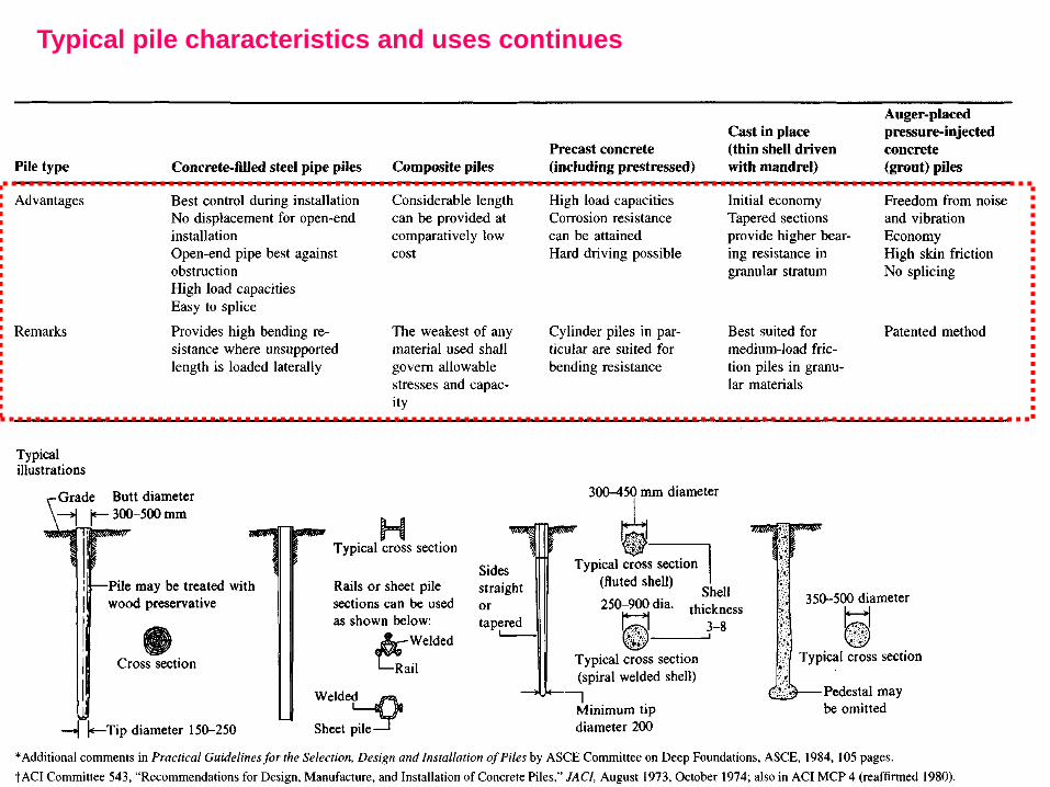
Typical pile characteristics and uses continues

A common use of concrete precast piles is in
marine sites where the soils are soft and loose.

Driving Steel Piles

Dwelling Building – temper pile

Drilled Shafts
- Built by vibrating a steel casing into the ground and
then filling it with concrete.
- Casings are removed as the concrete is being placed in
the shaft.
- The casings are light, easy to handle, cut, and splice.
- The shafts are clean out and visually inspection before
filling with concrete.
- In expansive soils, the shafts are filled as soon as
possible to avoid damage due to lateral soil pressures.

Drilled Shafts
The elements of a drilled shaft.
Notice the “bell” at the bottom
of the shaft, also called “underreaming”.
This expanded shaft
serves to increase the bearing
area by as much as 50% of the
shaft’s capacity.

auger rig & bit
A 5-foot diameter auger bit,
being centered over the surveyed
location of the shaft.

Transfer of Load
The way that the load from a column transfers into the soil through the pile has evolved during the past fifty years, from Terzaghi at the extreme left figure, through to Prieto (1978) on the extreme right.

The Behavior of Soils Around a Driven Pile.
The effect of pile is reflected in remolding the soil around the pile. Sands and clays respond to pile driving differently. First, we describe the behavior of clays and then the behavior of sands.
Clays.
The effects of pile driving in clays are listed in four major categories: 1. Remolding or disturbance to structure of the soil surrounding the pile
2. Changes of the state of stress in the soil in the vicinity of the pile
3. Dissipation of the excess pore pressure developed around the pile
4. Long term phenomena of strength regain in the soil
The essential difference between the actions of piles under dynamic and static loading is the fact that clays show pronounced time effects, and hence the show the greatest difference between dynamic and static action. These effects may be mechanistically described as follow.
Let us consider piles driven into a deep deposit of a soft impervious saturated clay. Since a pile has a volume of many cubic feet, an equal volume of clay must be displaced when the pile is driven.
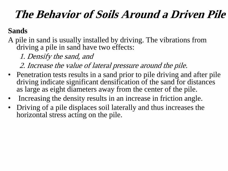
The Behavior of Soils Around a Driven Pile
Sands
A pile in sand is usually installed by driving. The vibrations from driving a pile in sand have two effects:
1. Densify the sand, and
2. Increase the value of lateral pressure around the pile.
• Penetration tests results in a sand prior to pile driving and after pile driving indicate significant densification of the sand for distances as large as eight diameters away from the center of the pile.
• Increasing the density results in an increase in friction angle.
• Driving of a pile displaces soil laterally and thus increases the horizontal stress acting on the pile.

Group Action of Piles
Piles are driven in groups at a spacing ranging from 3 to 4B where B is the diameter or side of a pile. The behavior of piles in a group may be quite different than that of a single pile if the piles are friction piles. This difference may not be so marked in bearing piles.

Negative Skin Friction
If a pile is driven in a soft clay or recently placed fill and has its tip resting in a dense stratum , the settlement of both the pile and the soft clay or fill is taking place after the pile has been driven and loaded. During and immediately after driving, a portion of the load is resisted by adhesion of soft soil with pile. But, as consolidation of the soft clay proceeds, it transmits all the load onto the tip of the pile.
In case of a fill, the settlement of the fill may be greater than that of the pile. In the initial stages of consolidation of the fill, it transmit all the load resisted by adhesion onto the tip of the pile. A further settlement results in a downward drag on the pile. It is known as negative skin friction. Both these cases should be recognized in the field in the design of bearing piles. When this condition occurs, the pile must be capable of supporting the soil weight as well as all other loads that the pile is designed to carry. Also, if fill is to be placed around an existing pile foundation, the ability of the piles to carry the added load should be thoroughly investigated.

Piles in a soft soil overlying a dense strata
(a) Skin friction immediately and during pile driving,
(b) negative skin friction afterwards.

Static Pile Capacity

Equations for Estimating Pile Capacity • The ultimate load-carrying capacity Qu of a pile is given by the
equation
Qp = load-carrying capacity of the pile point
Qs = Frictional resistance (skin friction) derived from the soil-pile interface

Point Bearing Capacity Remember General Bearing Capacity given by
It can be written as
For pile with width , D can be written as
Since D is small, third term become negligible
load-carrying capacity of the pile point is given as
Ap = area of pile tip
c' = cohesion of the soil supporting the pile tip
qp = unit point resistance
q' = effective vertical stress at the level of the pile tip
N*C Nq* = the bearing capacity factors
where

The Frictional Resistance
The Frictional, skin, or shaft resistance of a pile may be written as
where
Allowable Load, Qall
where
Qall = Allowable load-carrying capacity for each pile
FS= Factor of Safety

Static Pile Capacity
• All static pile capacities can be computed
by the following equations:
where Pu = ultimate (maximum) pile capacity in compression
Tu = ultimate pullout capacity
Ppu = ultimate pile tip capacity
Psi,u =ultimate skin resistance capacity
Pp = tip capacity
W = weight of pile being pulled
= summation process over I soil layers making up the soil
profile over length of pile shaft embedment

Static Pile Capacity
This value of Pa or Ta should be compatible with the capacity based
on the pile material (timber, concrete, or steel) considered earlier;
and SF/ represents the safety factors, which commonly range from
2.0 to 4 or more, depending on designer uncertainties.

Meyerhof's Method for Estimating Qp For tip Pile rest on Sand
Shall not exceed
where p, = atmospheric pressure
(=100 kN/m2 or 2000 Ib/ft2)
' = effective soil friction angle
of the bearing stratum
Clay (T = 0)
For piles in saturated clays under
undrained conditions (T = 0),
where cu = undrained cohesion of the soil below the tip of the pile.

Coyle and Castello's Method
Coyle and Castello's Method Applied
for Estimating Qp in Driven Pile in Sand
where
q' = effective vertical stress at the pile tip
N*q = bearing capacity factor

Frictional Resistance (Qs) in Sand
L' = 15D
The unite skin friction
increasingly with depth until
critical depth L’ which
approximately 15 to 20 D
is the friction angle between the soil and the pile or the
shaft: ranges between 0.5 to 0.80
Where o is the effective stress at each level considered

Coyle and Castello's Method
Coyle and Castello's Method Applied
for Estimating Qs in Driven Pile in Sand
where
= average effective overburden pressure
= soil-pile friction angle = 0.8‘
K from the chart
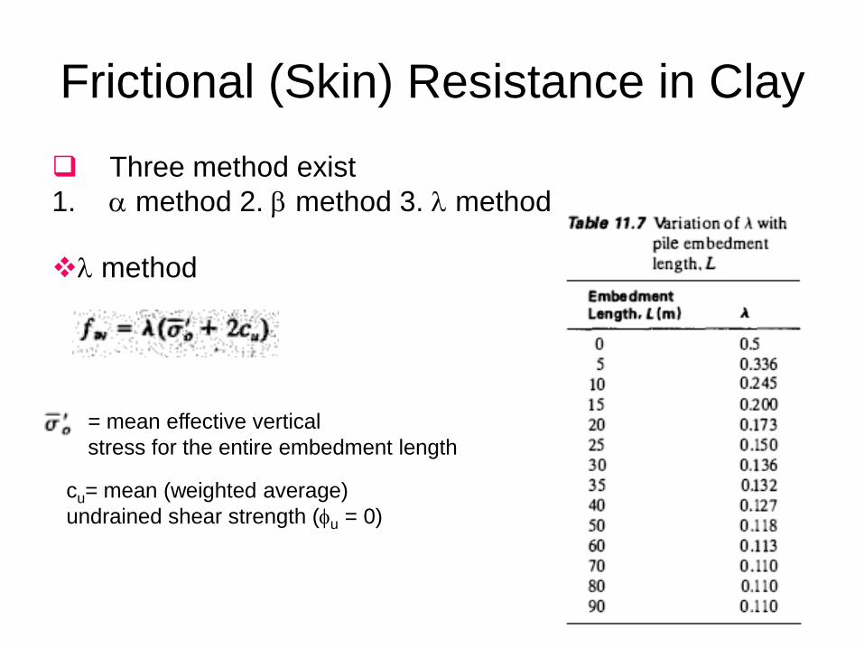
Frictional (Skin) Resistance in Clay
Three method exist
1. method 2. method 3. method
method
cu= mean (weighted average)
undrained shear strength (u = 0)
= mean effective vertical
stress for the entire embedment length

Frictional (Skin) Resistance in Clay Method (total stresses)
Method (effective stress)

Point Bearing Capacity of Piles Resting
on Rock
FS shall be 3

Example 1
1. Estimation of the load bearing capacity of a driven-pipe pile with a diameter of 406mm using , and
2. Point resistance
3. Allowable net carrying capacity
Have Example 2 on sand
Deposits

Pile-load Tests
Use of a hydraulic jack reacting against dead weight to
develop the test load in a static load test

Use of a hydraulic jack reacting against a beam and
reaction piles to develop the test load in a static load test

Estimate pile capacity

Actual Pile
Test

Elastic Settlement of Piles
• The total settlement of a pile under a vertical working load Qw is given by

Page 544

Piles in soil. Pile-to-soil friction
Piles in soil. Pile-to-soil friction tan defined for pile perimeters
shown; HP pile has two values; all others have a single value.

Ultimate Static Pile Point Capacity Ppu = Ap(cN'cdcsc + q-Wqdqsq + ½'BpNs)
Ap = area of pile point effective in bearing,
c = cohesion of soil beneath pile point (or su)
Bp = width of pile point
N'c = bearing capacity factor for cohesion
dc = 1 +0.4tan-1(L/B)
when = 0; c = su; N'c 9.0
N'q = bearing capacity factor
dq = 1 + 2 tan (1 - sin )2 tan-1 L/B
N’ = bearing capacity factor for base width = N
q’ = L = effective vertical (or overburden) pressure at pile point
= 1.0;
Ko=Coefficient of earth pressure at rest

Bearing-capacity factors N'c and N'q by
and Vesic's equations
The rigidity index Ir is computed using the shear modulus G' and
soil cohesion and shear strength s (or ) as

Bearing-capacity factors N'c and N'q by
and Vesic's equations

Bearing-capacity factors N' and N'q

Pile Skin Resistance Capacity
PS=
As = effective pile surface area on which fs acts;
computed as perimeter X embedment increment L
L = increment of embedment length (to allow for soil stratification
and variable pile shaft perimeters in the embedment length L)
fs = skin resistance to be computed by on of the following methods:
1.
2.
3.

The Method
where
= coefficient from Fig. 16-14
c = average cohesion (or su) for the soil stratum of interest
adhesion factor vs. undrained shear strength su.

factor for side-friction computations in
drilled shafts

The Method
where su = undrained shear strength of soil previously defined (kPa, ksf)
effective overburden pressure to the average depth of pile segment or 1/2 full depth.
For tapered piles you may have to use
element lengths L and do a summation, .
= coefficient from Fig,
is pile length-dependent,
and applies over the total pile embedment depth

The -Method

Tension Piles
piles For Resisting Uplift
Tension piles may be used beneath buildings to resist uplift from
hydrostatic pressure.
Psi = skin resistance from the several strata over the embedment
depth L and is computed as
Ppb = pullout capacity from base enlargement (bell);
may also be from Suction but suction is usually transient
W = total weight of pile or drilled pier/caisson

Additional upward capacity
in deep foundations with enlarged bases.

Breakout factor, Nu, for foundations
with enlarged bases in sandy Soils
N’c as before
For sand use Nu
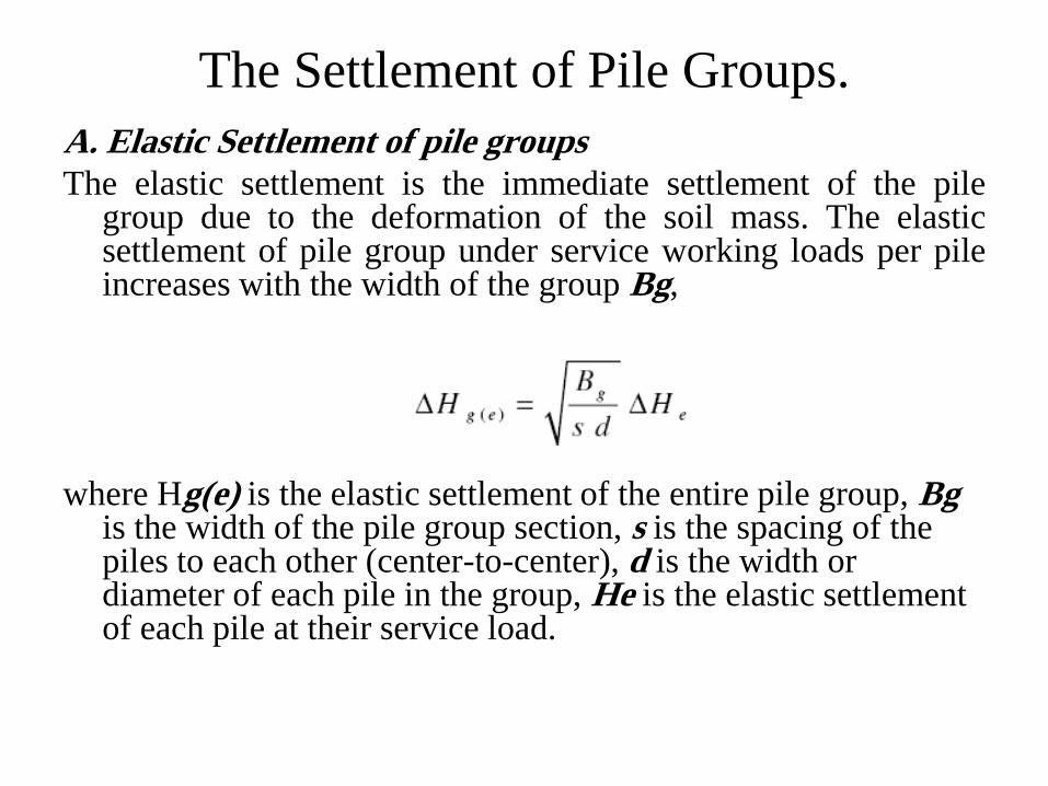
The Settlement of Pile Groups.
A. Elastic Settlement of pile groups
The elastic settlement is the immediate settlement of the pile group due to the deformation of the soil mass. The elastic settlement of pile group under service working loads per pile increases with the width of the group Bg,
where Hg(e) is the elastic settlement of the entire pile group, Bg is the width of the pile group section, s is the spacing of the piles to each other (center-to-center), d is the width or diameter of each pile in the group, He is the elastic settlement of each pile at their service load.

Elastic Settlement of A Single pile-pier
• The settlement of a pier is the axial shortening of the shaft +
the point settlement, written as
H=Hsi + Hp
Hsi = accumulation of shaft axial compression,
=PL/AE
• HP = point settlement due both to the point bearing pressure
and to settlement caused by skin resistance

Consolidation settlement of Pile Groups.
The simple stress distribution below the
pile group is the 2:1 stress method,

Consolidation settlement of Pile Groups

Estimates of the bearing capacity of pile
groups upon soils
To estimate the ultimate bearing capacity of group piles Qg(u) , choose the smaller of,
Estimate of the bearing capacity of pile groups upon rocks.
Most building codes permit Qg(u) = Qu
provided that the minimum distance from center-to-center of each pile is d + 300 mm.
For H-piles and piles with square cross sections, d is the diagonal distance.

The bearing capacity factor Nc* for a pile
group in clay soils.

factor for side-friction computations

Pile Group Efficiency

Calculate The Group’s Efficiency
1) The Converse-LaBarré method. In all methods, is the symbol used for the group’s efficiency expressed as a percentage of the theoretical total group load. The theoretical group load is obviously the ultimate load of each pile multiplied by the total number of piles. The ni represents the number of rows and columns, d is the pile diameter and s is the spacing between piles (center-to-center).
2) The Sand rule is used for piles carried through friction in sand,

Drilled Shafts and Caissons
Introduction.
Drilled shafts are the most popular of deep foundations, because they have the capability that one single shaft can easily carry the entire load of a large column from a tall building. This means that a pile cap is not needed, which not only reduces that expense, but also provides a smoother flow of the stresses from the column into the bearing soils
The Advantages of Using Drilled Shafts. 1. A single drilled shaft replaces a group of piles and their pile cap.
2. Can be constructed in dense soils easier than driving piles.
3. There is no noise or ground vibration from hammering.
4. Piles driven into soils may produce ground heaving which can cause previously driven piles to move laterally.
5. The base of a drilled shaft can be enlarged to provide a greater resistance to uplift (under-reaming).
6. The surface over which the base of the drilled shaft is constructed can be visually inspected.
7. Drilled shafts have very high resistance to lateral loads.

Disadvantages of Drilled Shafts
Disadvantages of Drilled Shafts.
- The designer needs a greater knowledge of the subsurface conditions.
- The large concrete volumes require careful supervision.
- Drilled shafts may induce ground loss to adjacent retained structures: increased liability.
- Inspections and supervision are far more complex.

Types of Drilled Shafts.

Construction Methods:
1. Circular holes are excavated by
hand for depths of 2 to 6 feet.
2. The sides of the hole are lined
with vertical lagging boards.
3. The boards are then held
together with steel rings.
4. The excavation continues for the
next 2 to 6 feet, etc.

The Construction Sequence of Drilled
Shaft

Casing
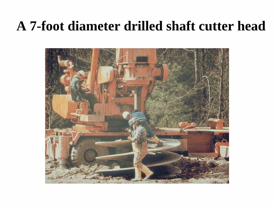
A 7-foot diameter drilled shaft cutter head

A special cutting tool for loose or
collapsing soils.


![Pile Foundation Design[1] - ITDmtp.itd.co.th/ITD-CP/data/PileFoundationDesign.pdf · Introduction to pile foundations Pile foundation design Load on piles Single pile design Pile](https://img.pdfslide.us/doc/110x75/5a6ffb387f8b9ab1538b8376/pile-foundation-design1-itdmtpitdcothitd-cpdatapilefoundationdesignpdfpdf.jpg)