Embed Size (px)
Citation preview

1
Seminar on Challenges in Fuel cell Technology: India’s PerspectiveIndian Institute of Technology- Delhi
1st and 2nd December 2006
Prof. R. NatarajanEnergy CentreVIT University
Vellore-14
PROSPECTS, CHALLENGES AND IMPEDIMENTS IN THE DEVELOPMENT OF BIOMASS GAS BASED
SOLID OXIDE FUEL CELL (SOFC) IN INDIA
Contents of the LectureIntroduction
Types of fuel cell
Solid Oxide Fuel Cell Reaction and Configuration
Important Components of the Solid Oxide fuel cell
Salient features of the components and performance
Prospects of Solid Oxide fuel cell systems
Challenges in Solid Oxide Fuel cell Development
Experience of VIT in Solid Oxide Fuel Cell program
Impediments in the realization
Conclusion and Suggestions for the future
What is a fuel cell?• A fuel cell is an electrochemical device that combines hydrogen or
other fuels and oxygen to produce electricity, with water and heat as its by-product. As long as fuel is supplied, the fuel cell will continue to generate power. Since the conversion of the fuel to energy takes place via an electrochemical process, not combustion, the process is clean, quiet and highly efficient – two to three times more efficient than fuel burning.
• No other energy generation technology offers the combination of benefits that fuel cells do. In addition to low or zero emissions, benefits include high efficiency and reliability, multi-fuel capability, Operation flexibility, durability, and ease of maintenance. Fuel cells are also scalable and can be stacked until the desired power output is reached. Since fuel cells operate silently, they reduce noise pollution as well as air pollution and the waste heat from a fuel cell can be used to provide hot water or space heating for a home or office.
Types of Fuel CellsFuel Cell Designation Electrolyte Temperature
°CCell
Efficiency (Load Partial Load)
Type of Application
Alkaline Fuel Cell AFC Aqueous KOH
60.. .90 50.. .60 Mobile, stationary
Polymer Electrolyte Fuel Cell
PEFC 50.. .80 50.. .60 Mobile, stationary
Direct Methanol Fuel Cell
DMFC 110.. .130 30.. .40 Mobile
Phosphoric Acid Fuel Cell
PAFC H3P04 160.. .220 55 Stationary
Molten Carbonate Fuel Cell
MCFC Alkaline carbonates
620.. .660 60...65 Stationary
Solid Oxide Fuel Cell
SOFC ZrO2 800.. .1000 55.. .65 Stationary
Polymer electrolyteMembrane
Reference : Automotive handbook – MICO
ELECTROCHEMICAL REACTIONS OCCURRING IN DIFFERENT TYPES OF FUEL CELL
Taken from R.M.Dell and D.A.J.Rand, clean energy, the Royal Society of Chemistry, UK,2004
Solid Oxide Fuel Cells
2
Reactions in Solid Oxide Fuel Cell Types of SOFCs
• Tubular– Extremely expensive production– Low power density
• Planar– High power density– Lends itself to mass production
Types of SOFCs
• Tubular– Extremely expensive
production– Low power density
• Planar– High power density– Lends itself to mass
production
SOFC Advantages and Limitations • Advantages
– Being operated at high temperatures and cooling is done by air, there is no water management problem.
– Can handle many conventional fuels, CO is also a fuel, and is more tolerant to higher concentrations of hydrocarbons and sulfur than for the PEMFC.
– Considerably less complex fuel reforming compared to PEMFC. Particularly, natural gas fuel can be reformed within the stack,
– With cogeneration, the system efficiencies can be quite high and flat over the operating temperature range.
– Very low level of NOx and SOX emissions.– Pressurized SOFC can replace the combustor in a gas turbine power plant to
reach the efficiencies up to 70%.• Limitations
– High operating temperatures mean it requires special materials tolerant to those temperatures.
– Sealing and thermal cycling are major problems.– Longer start-up time.
Application of Solid Oxide Fuel cell
• The development of planar type SOFC is being pursued worldwide by many companies in USA, Europe and Japan.
• The focus for the development Is in auxiliary power supply of the order of magnitude 5 kW.
• The applications include auxiliary power for trucks when parked to reduce the significant waste of diesel by running the truck in idle overnight. The expected savings could be around 450,000 gallons of diesel annually only in the USA!
• Planar SOFC are being considered also for home electric power needs to become semi-independent of the grid power.
• Typical unit consist of about 10x10 cm size plates with two stacks consisting of about 40-50 cells connected in series.
Combined Heat and Power (CHP) systems
• The Siemens-Westinghpuse's SOFC power system has shown 46% electric efficiencies in pilot power plant. Small tube bundles have operated over 40,000 hours and a record 69,000 hours for a single tube SOFC.
• Combined-cycle system in which the fuel cell replaces the burner in a gas turbine cycle could achieve the overall system efficiency of over 70%.
• The high temperature fuel cell thus can exceed the efficiencies achieved today by combined gas and steam turbine (60%).
• The high temperature fuel cell can also tolerate many fuels and fuel impurities.
• For small-scale CHP technology (~100 kW to several MW), all fuel cell systems can be used.

3
SOFC & Steam Turbine Combined Cycle
MANUFACTURING TECHNIQUES FOLLOWED FOR SOFC
SOFC Single Cell and StackArrangement
Cathodes Improved Performance
• Improved Microstructure• Reaction Mechanisms• Component interconnections• Mixed Conductivity• Cost
Anodes Oxygen, Sulfur and Carbon Tolerance
♦ Re- oxidation when exposed to Air♦ Sulfur tolerance♦ Carbon tolerance ♦ Internal reforming♦ Cost
Important components and Requirements
Electrolytes The function of electrolyte is to separate the two gas atmospheres and to transport the oxygen ions without significant losses from the cathode to the anode.
♦ It should have sufficient oxygen ion conductivity♦ Minimum voltage loss across the electrolyte♦ Stable under oxidizing condition♦ Should have sufficient mechanical strength♦ Yttria stabilized Zirconia (ysz) is extensively used♦ Alternate electrolyte materials are perovskitiees based
on LaGaO3 doped with ceria.♦ Should be chemically stable in large oxygen partial
pressure gradient potential
Important components and Requirements- Cont.
Interconnects(Bipolar plates)
The interconnect has to meet the following demands
♦ High electronic and low ionic conductivities (electrical conductivity > 1 S cm-1)
♦ Chemical stability under the reducing and oxidizing conditions at the anode and cathode sides of the cell at temperature of up to 1000C (Range of oxygen activity 10-18-1 bar)
♦ Gas tightness;♦ Thermal expansion coefficient matching with that of
other cell components ♦ Low costs.
Seals Leakage and Stress Hydrogen Leakage Rigidity of Stack Volatility and Stability of seal material Cost
Important components and Requirements - Cont.

4
Important components and Requirements - Cont.
Components for reactant supply and products outlet
For the supply of hydrogen and other fuels to the anode and oxygen/air to the cathode and to evacuate H2O and CO2 products
1. It should withstand hgh temperature oxidation / reduction reactions
2. Leak proof connection to the end plates
Instrumentation 1. To measure the temperature, pressure, voltage and current of the cells, intermediates and electrodes
Materials for SOFC applications Electrolyte YSZ, ScSZ, CeO2 (mod.) LaGaO3 (mod.)
Anode Ni/YSZ, Ni/CeO2 (mod). Cu/YSZ, Cu/CeO2 /YSZ, Ni/SrTi1-xNb~ 3, Ni/LaxSr1-x TiO3, Ni/Y,Zr, Ti)O2, Ni/(Y,Sc,Zr,Ti)O2, Ni/Sr2Ga NbO6
Anode substrate
Ni/YSZ, Ni/Al2O3, Ni/TiO2, Ni/NiCr2O4
Cathode (La, Sr, Ca)MnO3, (La, Sr, Ca)CoO3, (Pr,Sr,Ca)MnO3, La(Sr,Ca)FeO-3, La(Ni,Fe)O3
Interconnect, Ceramic/metallic
LaCrO3 (mod). Ferritic Steel Cr-based alloys, Austenitic steel
Sealing Glass, Glass ceramic, Metallic gasket
ExtrusionDrying
SinteringPlasma spraying
Interconnect
Sintering Ni-dipping Electrochemical vapor deposition
Electrochemical reaction
CathodeAnode Electrolyte
Tape Casting Screen PrintingSinteringAnode Cathode
Co- finingElectrolyte
Tape Casting Screen PrintingPre –
SinteringAnode Electrolyte
SinteringWet powder
spraying Sintering
Cathode
c) the anode-supported design
a) the tubular design
b) the electrolyte-supported design and
CURRENT PROCESSING TECHNIQUES USED FOR SOFC
Processing / Fabrication Techniques used for Fuel Cell Elements
• Siemens Westinghouse tubular design– Cathode acts as substract / carrier
– Electrolytes are deposited on the cathode followed by anode and
– Interconnect is running along the length for distributing the reactants.
– Tubular cell was originally made by vapor deposition. Number of layers are formed depending upon the requirement
• Mitsubishi Heavy Industry– Made the substrat by Plasma spray later switched over to sintering method to
reduce the cost
– Sintering method gives porous substrat giving problem in depositing interconnect films.
• TOTO, Japan– Followed slurry coating technique using LaMnO3 Casting/ extrusion mould
technique
– The Electrodes are then coated by dipping process or by printing method
Processing scheme for SOFC fabrication by tape calendaring (filled arrows) and by tape casting (hollow arrows) Schematic Diagram of Extrusion Process

5
Schematic of the Slurry Coating (Dipping) Process. Printing Method for Tubular Cell Preparation
Tape casting of SOFC cell
Planar SOFCs: Microstructure

6
Correlation between screen and paste film on the substrate SCREEN-PRINTING PROCESS
Details of the SOFC Project under progress in VIT
Project Funding DetailsProject title “Development of Technology for
Upgradation of Producer Gas From Biomass Gasifier As Feed Stock In Solid Oxide Fuel For Power Generation”
Project funded by Department of Science and Technology (DST)
Project No. SR/S3/MERC/11/2005-SERC-Engg. The total amount allocated for this project
Rs. 21,52,800 /-
Rs. 17,94,000/-For Institutional overheads
Rs. 3,58,800/-
Additional funding from VIT
Rs. 10,00,000/-
Duration of the Project 30 months
FUEL CELL MANUFACTU
RERS
FUEL CELL LOCATION
AcumentricsCorporation(USA)
5 kW tubular SOFC beta unit
♦ Cleveland, Ohio.♦ Japan♦ Sheridan, Wyoming
♦ Seward, Alaska♦ Houston, Texas♦ Idaho Falls, Idaho
Ceramic Fuel Cells Ltd. (CFCL)Australia
1 kW Micro-CHP SOFC
♦ South Melbourne, Australia
♦ Chadstone, Australia
♦ Brandenburg, Germany
♦ State of Tasmania, New Zealand
♦ Wellington, New Zealand
♦ Oldenburg, Germany
ORGANIZATIONS CONTACTED FOR THE SUPPLY OF SOFC ELEMENTS
FUEL CELL MANUFACTUR
ERS
FUEL CELL LOCATION
Fuel Cell Technologies (FCT)Canada
5 kW SOFC ♦Mississauga, Canada♦Ft. Meade, Maryland♦Kingston, Canada♦Itajuba, Brazil♦Vancouver, Canada♦Pittsburgh,
Pennsylvania♦Liege, Belgium♦Parker Dam State
Park, Pennsylvania♦Fairbanks, Alaska♦Mechernich and
Essen, Germany
♦Yokohama, Japan♦Dearborn, Michigan♦Vancouver, Canada♦Kingston, Canada♦Morgantown, West Virginia♦Memphis, Tennessee♦San Francisco, California♦Stockholm, Sweden♦Various locations, California
Global ThermoelectricUSA
2 to 5 kW SOFC systems
♦Various locations, USA♦Billings, Montana♦Calgary,
Minaton (Russian Ministry of Atom)
1 kW SOFC ♦Snezhinsk, Russia
ORGANIZATIONS CONTACTED FOR THE SUPPLY OF SOFC ELEMENTS

7
FUEL CELL MANUFACTURERS
FUEL CELL
LOCATION
Mitsubishi Heavy Industries (MHI), Japan
150-200 kW SOFC
♦ Japan
Siemens Power Generation, IncGermany
400W to 300 kW SOFC CHP
♦ Turin, Italy♦ Alaska♦ Hannover, Germany♦ Sinetta Marengo, Italy♦ Nikiski, Alaska♦ Toronto, Canada♦ Mississauga, Canada♦ Bergen, Norway
♦ Essen, Germany♦ Toronto, Canada♦ Austria♦ Irvine, California♦ Irvine, California♦ Westervoort, Netherlands;
Essen, Germany♦ Japan
Sulzer HexisSwitzerland
1 kW HXS 1000 Premiere
♦Dresden, Germany♦Zurich, Switzerland♦Northwestern
Switzerland♦La Plaine Saint-Denis,
Paris, France♦Berlin-Buckow, Germany♦Gadebusch, Germany♦Barby, Germany♦Weimar, Germany♦Various locations,
Germany
♦ North Rhine-Westphalia area, Germany
♦ Essen, Germany♦ Attnang Puchheim, Austria♦ Petten, Netherlands♦ Lully, Switzerland♦ Tokyo, Japan♦ Groningen, Netherlands♦ Bilbao, Spain♦ Basel, Switzerland♦ Winterthur, Switzerland
ORGANIZATIONS CONTACTED FOR THE SUPPLY OF SOFC ELEMENTS
FUEL CELL MANUFACTURERS
FUEL CELL
LOCATION
Tokyo GasJapan
SOFC ♦ Japan
ZTEK Corp.USA 25 kW SOFC
♦ Rocky Hill, Connecticut♦ Huntsville, Alabama♦ Japan
International fuel cell USA SOFC ♦ USAGesellschaft fur innovative Eenrgie und Wasserstoff-Technologie mbH (ET)
SOFC ♦ Brunnthal, Germany
Gastech Technology BV SOFC ♦ Apeldoorn, NetherlandsFuel Cell Institute of Australia Pty Ltd (FCIA)
SOFC ♦ Cabramatta NSW, Australia
ORGANIZATIONS CONTACTED FOR THE SUPPLY OF SOFC ELEMENTS
FUEL CELL MANUFACTURERS
FUEL CELL LOCATION
Global Photonic Energy Corporation
SOFC ♦Ewing NJ, United States.
Electrochem, Inc. SOFC ♦Woburn MA, United States
Electric Fuel Limited SOFC ♦Beit Shemesh, Israel
Agni Energie Sdn Bhd SOFC ♦Shah Alam, Malaysia
HT Ceramix SOFC ♦Switcherland
InDEC SOFC ♦Netherland
ORGANIZATIONS CONTACTED FOR THE SUPPLY OF SOFC ELEMENTS
Firms responded for the supply of SOFCs and components
• HT Ceramix- Switcherland for the supply of 100W fuel cell stack with strict conditions
• Indec – Netherland for the supply of anode, and electrolyte fuel cell elements
• Others had regretted or suggested to contact the above suppliers
Price of fuel cellsPrice (US$ per kW
ForecastPresent
Stationary TransportationPhosphoric acid (PAFC) 4000-4500 1500Polymer electrolyte membrane (PEMFC
3500-15000 700-800 30-50
Molten carbonate (MCFC) >15000 1500
Solid Oxide Fuel Cell (SOFC): tubular design with/without micro-tubine
10000-25000 1200 for 1-5MW plants
Solid Oxide (SOFC): Planar design
>10000 700-1000
Fuel Cell
The terms and conditions given by the suppliers of the Solid oxide fuel cell
HT ceramix supplier of fuel cell stack.
• HT Ceramix, Switcher land – Offer against the purchase enquiry HT Ceramix 100W five cell stack
Total cost - Є 24,150 : Rs. 14,24,850 and for 20W Є 20,400, Rs.12,36,000
• HTc agrees to supply a stack for educational / technical evaluation purpose laboratory/ prototyping conditions.
• HTc grants a free, non-exclusive non-transferable license limited to the sole purpose evaluation HTc’ SOFC stack.
• The stack should be tested as per procedure outline by HTc. If HTc products applied failure by the customer to communicator to and consult with HTc on testing and evaluation procedures or any other purpose to which HTc products are applied invalidates all or any warranty, product liability, patent infringement or indemnification, express or implied, for which HTc may be liable world wide.
8
• The customer shall not allow its collaborators or anyone else to reverse engineer or execute analysis of any kind either directly or indirectly on the dimensions, chemical composition, microstructure, surface morphology, method of manufacture or assembly of the cell, as diffusion & distribution layer, current collection layer and the stack itself.
• The customer, upon the completion of the useful life of the stack, shall return the stack to HTc for appropriate disposal.
• The stack initial performance is guaranteed for 24 hours if the HTc startup procedure is followed and the operating condition respected.
• The HT ceramix has suggest to buy the test equipments from Advanced Measurements, Canada.
• These results were obtained under our ideal laboratory conditions. HTceramix offers no guarantee of identical performance under other laboratory conditions.
• This offer is made pursuant to the laws of the Canton de Vaud, Switzerland.
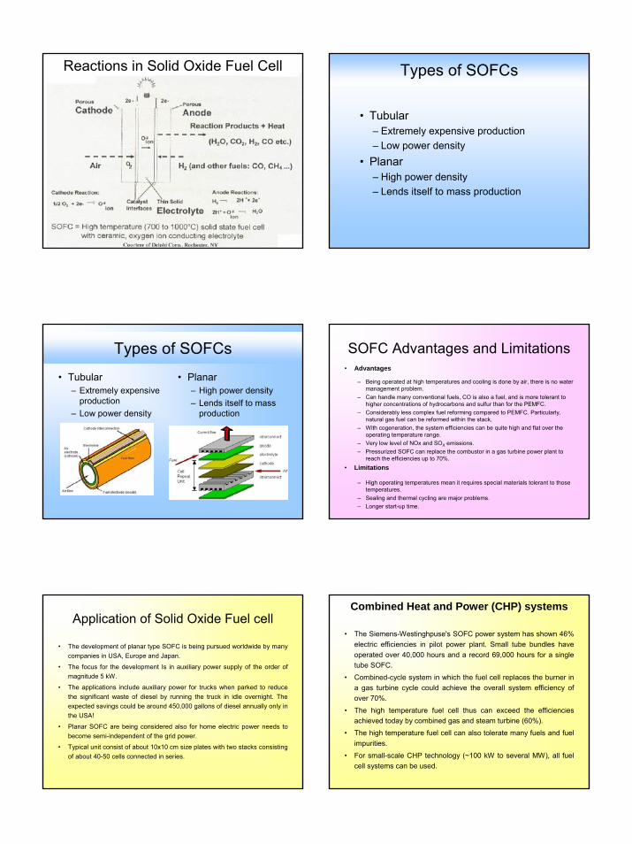
The terms and conditions given by the suppliers of the Solid oxide fuel cell
HT ceramix supplier of fuel cell stack. (cont.)HOT COMPRESSION KIT
INSULATING PLATE AND A TEST FIXTURE
• InDEC (HC Starck), Netherland – Offers only fuel cell elements (anode, cathode and electrolyte)
– Do not offer the stack
– Has suggested to contact stack design engineers for consultancy and bear the consultancy charges.
– The consultancy charges for advising the stack engineering was indicated as us $ 25,000 however they do not give guarantee.
– Has suggested to buy the stack test equipment from (ECN)
– Has given offer for three types of fuel cell elements • Anode supported (ASC1, ASC2)
• Electrode supported cells (ESC2)
• We have to buy minimum 10 cells
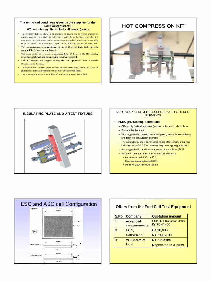
QUOTATIONS FROM THE SUPPLIERS OF SOFC CELL ELEMENTS
ESC and ASC cell Configuration Offers from the Fuel Cell Test Equipment
S.No Company Quotation amount1 Advanced
measurements $131,400 Canadian dollar Rs. 60,44,400
2. ECN, Netherland
Є1,28,000 Rs.73,45,011
3. VB Ceramics, India
Rs. 12 lakhsNegotiated to 8 lakhs.

9
Quotations from the suppliers of SOFC test rig.
S.No
Company Quotation amount
Remarks
1 Advanced measurements
$131,400 Canadian dollar
1. The supply includes a. Gas flow system with control for both
fuel and oxidizerb. Heat exchanger to cool producer gas
with airc. Pre heater to heat to 800C d. Furnace – 1000C rating -system e. Data acquisition and control f. Electronic Loadg. Piping and tubing
2. They will provided at extra cost the following Regulated supply of clean producer gas
a. Fuel cell manifoldb. UPSc. Gas detection (Can be offered at extra
cost)
Quotations from the suppliers of SOFC Test rig. (cont.)
2. ECN, Netherland
Є1,28,000 1. Informed over phone, detailed quotation yet to be received
2. ECN will provide support knowledge on assembly, conditioning / startup procedure, operation etc only when decide to purchase the test rig from them.
3. For information on stack design only when consultancy agreement signed and payment is made separately for this knowledge.
4. However ECN does not give guarantee whatsoever on performance, endurance as this technology is still under development.
3. VB Ceramics, India
Rs. 8 lakhs 1.The supply includes a. Producer gas pre treatment plantb. Compressor assemblyc. Reservoir tankd. Mass flow controllere. Heat exchangerf. Vacuum furnaceg. Pipe linesh. Electronic loadi. Control panelj. Data acquisition (controlled from the
control panel not from the computer)2.They will provided at extra cost the following
1. Data acquisition system and control software
Quotations from the suppliers of SOFC Test rig. (cont.)
The process followed for the purification of producer gas
LIST OF PROJECTS AND EQUIPMENTS USING PRODUCER GAS AS FEED STOCK
A. Preparation and refining of producer gas B. Common Furnace for Heating the working fluid
C. Solid oxide Fuel cell D. Common Control panel
S.NO LIST OF EQUIPMENTS S.NO LIST OF EQUIPMENTS
01 A REACTOR 07 HIGH PRESSURE INSULATED RECEIVING
02 SCREW CONVEYOR 08 B FURNACE CHAMBER WITH BURNER
03 CYCLONE SEPARATOR 09 HEAT TRANSFER TUBES
04 CERAMIC COARSE FILTER
a. TO HEAT THE PRODUCER GAS FROM 400-1000Cb. TO HEAT THE HELIUM FROM 30-750Cc. TO HEAT THE VEGETABLE OIL FROM 30-350C
05 CERAMIC FINE FILTER 10 C SOLID OXIDE FUEL CELL
06 COMPRESSOR 11 D CONTROL PANEL
Producer Gas Purification Unit

10
Producer Gas Purification Unit Ceramic Filter Elements -CALDO Engineering, UK
INSERTION OF CERAMIC FILTER INTO THE FILTER ASSEMBLY PROCESS FLOW DIAGRAM OF THE
TEST RIG FOR SOFC
LIST IMPORTANT EQUIPMENTS, COMPONENTS AND INSTRUMENTS
• Fuel processing Hot producer gas filtration equipment Cooling of producer gas – heat exchangerProducer gas compressorHigh pressure producer gas receiverPressure regulator for producer gasFlow measurement and control system for producer gasHeater for the producer gas to heat from room temperature to around 8500C Thermocouples 8 numbers Pressure sensors transducers 4 numbers Temperature indicator cum recorder – I No.
• Oxidizer processing – Air compressor– Air receiver – Air pressure regulator – Air flow meter and controller – Air heater from room temperature to around 8500C– Thermocouples 6 numbers – Temperature indicator cum recorder – I no. – Pressure sensors – 2 nos.– Flow meters with control valve
• Fuel cell assembly – Single / multi cell stack – 2 nos. – Fuel and oxidiser inlet plumbing lines and nozzles – 1 set– Producer gas
LIST IMPORTANT EQUIPMENTS, COMPONENTS AND INSTRUMENTS

11
• Fuel cell assembly – Single / multi cell stack
– Fuel and oxidizer inlet plumbing lines and nozzles
– Product gas piping
– Thermocouples
– Fuel cell furnace
– Fuel cell gaskets
– High temperature adhesive for fuel cell
• Performance evaluation equipments – Voltmeters, ammeter, Energy meter
– Data acquisition system with monitor and printer
• Fuel cell test equipment
• Tools and fixtures
LIST IMPORTANT EQUIPMENTS, COMPONENTS AND INSTRUMENTS Summary & Requirement
• Present status of research on SOFC in other laboratories in India– The following laboratories have reported that
they are carrying out research in fuel cell and also in SOFC.
• Central Glass and Ceramic Research Institute, Calcutta – CGCRI
• Central Electrochemical Research Institute, (CECRI), Karaikudi &Chennai
CGCRI, Kolkata`
Bhabha Atomic Research Center, Mumbai
BHEL, Bangalore CECRI, IIT, Chennai
IIT, Delhi
BHEL, HyderabadDRDO, Ambernath
NCL, PuneIIT, Mumbai
INSTITUTIONS CARRYING OUT RESEARCH AND DEVELOPMENT
WORK ON SOFC IN INDIA
IIT, Mumbai
Bhubaneshwar
CECRI, Karaikudi
BHU, Varanasi
Details from CGCRI, Kolkata on SOFC • CGCRI scientist working on the SOFC has informed that development of
kW level SOFC is one of the current multi crore CSIR –NMITLI project He was called back from abroad specifically to establish this laboratory
He has worked in USA, Germany, Canada and Japan for 8 years directly on SOFC with Siemens-Westinghouse/Penn state, Forschugszentrum Juelich and McMaster university and Ishihara’s group.
20 scientist including 5 JRFs are working on SOFC project in CGCRI
Have imported test rig to evaluate the performance
They are carrying out the research with commercially available pure hydrogen.
SOFC design is extremely complicated compared to PEM and PAFC stacks. In his opinion there is nobody working on SOFC with producer gas as feed stock.
Information from CECRI, Karaikudi is yet to be receivedFuel cell Research centre at Chennai has separate laboratory space with 7 scientist and supporting staff. CSIR has spent considerable amount in establishing facilities.
Research and Development Challenges for SOFC
SOFC Tubular design
• High cell and stack fabrication cost• Long start-up/shut-down times (upto several hours).• Significant thermal shielding required to avoid heat losses• Difficulties in the management of electrical and thermal load
demands, as well as in temperature maintenance.SOFC Planar Design
• Selection and poor life – time of interconnect and sealing materials
• Lower operating temperature so that cheap metallic interconnect materials can be used with minimal cell degradation.
• Poor thermal cycling capability• Sealing and thermal compatibility issues.• High rates of cell degradation during operation• Long start-up/ shut –down times (up to several hours).• Significant thermal shielding required to avoid heat losses. • Difficulties in electrical and thermal load demand, as well as
in temperature maintenance.

12
PROBLEMS FOR NEW DEVELOPERS(IMPEDIMENTS)
• It is too expensive for any new laboratory to attempt to developdifferent elements required for manufacturing Solid Oxide Fuel Cell.
• Laboratories around the world are reluctant to share their knowledge on practical aspects of solid oxide fuel cell.
• The fund made available from the funding agency in India is too meager to attempt any reasonable research and development on Solid Oxide Fuel Cell.
• Even the limited number of personals working on SOFC development are not having specific goal to commercialize the technology.
• Every scientist will be happy to see the outcome of his research is put into use for wider social cause. It is possible only when commercial scale production units are installed. The execution of any project calls for the contribution of different developing agencies with a team to co-ordinate and a lead person. It is time for India to plan creation of an organization exclusively for fuel cells research, development and manufacture.
• In the absence of a Central agency to integrate the research efforts of different laboratories, academic institutions in fuel cell research may go waste or under utilized as though there is no commitment in the country to commercialize Solid Oxide Fuel Cell based power plants.
PROBLEMS FOR NEW DEVELOPERS(IMPEDIMENTS) – cont.
CONCLUSION AND SUGGESTIONS• Government of India should form a separate
organization similar to ISRO to consolidate the research and development activities progressing in different laboratories and academic institution in the country and realize commercial scale plants in project mode.
– The present laboratories working on different element can also continue to do their research getting the fund through the centralized organization.
– The new organization should be given clear mandate for developing solid oxide fuel cell power plants integrated with cogeneration units
– In absence of creation of an exclusive organization, India will have only pockets of researchers carrying out research without any definite aim and purpose.
References1. Ioannis V.Yentekakis Open-and closed-circuit study of an
intermediate temperature SOFC directly fueled with simulated biogas mixtures., J Power Sources xxx(2006)xxx-xxx
2. J-H Choi and co authors Characteristics of Pulse Cleaning in the Ceramic Filter Unit at High Temperature., Department of Chem. Eng & IEP, Gyeongsang National University, Korea.
3. Market assessment for fuel cell in India: stationary and automotive applications An OPET-international action TERI Delhi.
4. Olga A.Marina and co authors “A solid oxide fuel cell with a gadolinia-doped ceria anode: preparation and performance. J Solid State Ionics 123 (1999)199-208.
References (cont.)5. Catalogue details of M/s Fuel Cell materials Ltd. Ohio
6. Catalogue and Technical information of M/s. NEXTECH materials Ltd. Ohio.
7. The Future of Fuel Cells – Benwiens Energy Science – 2005
8. Hand book of chemical process equipments – mechanical separation equipments.
9. J.D.J.VanderSteen and J.G.Pharoah “ The effect of radiation heat transfer in solid Oxide fuel cell modeling Combustion institute / Canadian section, spring technical meeting, Queen’s University, May 9-12 – 2004.
10. A report on “Australian Hydrogen Activity” Dr.D.A.J.Rand of CSIRO energy technology, and Dr.S.P.S. Badwal of CSIRO manufacturing and Infrastructure Technology, for the Department of Industry, tourism and Resources.
11. D.Stover, H.P.Buchkremer, J.P.P.Huijsmans MEA / cell preparation methods: Europe/USA, solid oxide fuel cells and systems, Chapter 72, pp.1015-1029.
12. M.Suzuki, Osaka Gas Co., Osaka, Japan, MEA / cell preparation methods: Japan/Asia, solid oxide fuel cells and systems, Chapter 72, pp.1032-1036.
Thank youThank you


![[Project Name] Post-Mortem - IIT Delhiweb.iitd.ac.in/~sbasu/seminar/presentation/7Dr. R.N. BasuCGCRI,Kolkata.pdfcoating/EPD/ Thermal Spray Anode-supported Planar Wet-powder spraying](https://img.pdfslide.us/doc/110x75/61126ea3265f95674661ea8b/project-name-post-mortem-iit-sbasuseminarpresentation7dr-rn-basucgcrikolkatapdf.jpg)