Embed Size (px)
Citation preview
Types of Cracking and Influencing
Causes
TRB Cracking Webinar May 25, 2016
R. Doug Hooton NSERC/ Cement Association of Canada, Senior Industrial Research Chair in Concrete Durability & Sustainability
UNIVERSITY OF TORONTO
DEPARTMENT OF CIVIL ENGINEERING

Many Potential Types of Cracks
Plastic
shrinkage Drying
shrinkage
Restrained
thermal &
drying
subsidence
Delayed joint
cuts
R D Hooton U. of Toronto, TRB
Webinar May 25, 2016

Volume Changes That
Influence Cracking
1. Chemical/ autogenous shrinkage
2. Plastic shrinkage, subsidence
3. Drying shrinkage
4. Thermal exp’n/contraction
5. Creep
R D Hooton U. of Toronto, TRB
Webinar May 25, 2016

Chemical Shrinkage of Hydrating
Cement
• Chemical shrinkage occurs due to the
reduction in absolute volume of solids and
liquids in the hydrating paste.
• Chemical shrinkage continues to occur as
long as cement hydrates.
• After initial set, the paste resists deformation,
causing the formation of voids in the
microstructure.
R D Hooton U. of Toronto, TRB Webinar May 25, 2016

R D Hooton U. of Toronto, TRB Webinar May 25, 2016
Chemical Shrinkage is not just
limited to cement hydration
• Occurs when the volume of the products of chemical reaction is smaller than the sum of the initial reactants.
• Eg. 0.50L of Ethanol mixed with 0.50L of water will only result in 0.96L of fluid (Wikipedia).
• Or 0.5L of cement mixed with 0.5L water, if well hydrated, will result in ~0.94L of hydrated solid material.

Autogenous Shrinkage
• Autogenous shrinkage is the dimensional change of
concrete caused by chemical shrinkage.
• When internal relative humidity is reduced below a
given threshold (i.e., extra water is not available),
self-desiccation of the paste occurs, resulting in a
uniform reduction of volume.
• Becomes significant at low water/cement ratios,
less than about 0.42
R D Hooton U. of Toronto, TRB Webinar May 25, 2016

R D Hooton U. of Toronto,
TRB Webinar May 25, 2016
Chemical and Autogenous Shrinkage of
Cement Paste
Figure from PCA Design & Control of
Concrete Mixtures ASTM C1698
ASTM C1608
Becomes significant at low w/cm
typical of HPC mixtures

R D Hooton U. of Toronto, TRB
Webinar May 25, 2016
Volumetric Relationship Between — Subsidence, Bleed Water, Chemical and
Autogenous Shrinkage
PCA Design & Control of Concrete Mixtures
Before
set After
set

R D Hooton U. of Toronto, TRB Webinar May 25, 2016
Window of Finishability or
Window of Plastic Shrinkage Cracking
3.4MPa (500 psi)
27.6MPa (4000psi)
Begin
Finishing
End Finishing
Pen
etr
ati
on
Resis
tan
ce
Time (hours) Figure from K. Hover

From initial float until time of set and application of curing

Plastic Shrinkage Cracks on HPC
Bridge Deck (delayed set & lack of evaporation control)
R D Hooton U. of Toronto, TRB
Webinar May 25, 2016

R D Hooton U. of Toronto, TRB Webinar May 25, 2016
Sprayed on Evaporation Retarder

R D Hooton U. of Toronto, TRB Webinar May 25, 2016
Fog Misting from Upwind Edge

R D Hooton U. of Toronto, TRB Webinar May 25, 2016
One short plastic crack near edge of deck

Epoxy Repair of plastic shrinkage
cracks on new bridge deck (~1991)
good concrete between the cracks R D Hooton U. of Toronto, TRB
Webinar May 25, 2016

Drying Shrinkage and Cracking
Cracking results from restraint.
R D Hooton U. of Toronto, TRB
Webinar May 25, 2016

Influence of Wet Curing on
Shrinkage
More curing reduces on-set and rate of drying shrinkage
R D Hooton U. of Toronto, TRB Webinar May 25, 2016

Drying Shrinkage and Water Content Specifying min. cement
contents prevents
producer from reducing
unit water content of
mixture
Use of water reducers
will reduce shrinkage
Less shrinkage with
more aggregate (better
packing & larger max.
size agg.)
Figure from PCA Design &
Control of Concrete Mixtures
200kg/m3 = 333 pcy
150kg/m3 = 250 pcy

Thermal Cracking
• Can result from excessive temperature
gradients resulting from heat of hydration
of cement.
• Can also result from restraint from
adjacent cool temperature components
preventing contraction on cooling (often
seen on barrier walls dowelled into
previously placed base slabs, with cracks
starting from the bottom). R D Hooton U. of Toronto, TRB
Webinar May 25, 2016

Heat Rise in Concrete Due
to Hydration of Cement
As concrete heats up it swells, then it contracts on cooling
back to ambient temperature----inducing tensile stresses
R D Hooton U. of Toronto, TRB
Webinar May 25, 2016
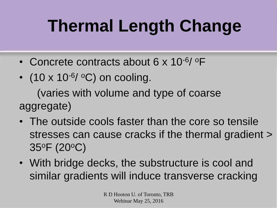
Thermal Length Change
• Concrete contracts about 6 x 10⁻⁶/ oF
• (10 x 10-6/ oC) on cooling.
(varies with volume and type of coarse
aggregate)
• The outside cools faster than the core so tensile
stresses can cause cracks if the thermal gradient >
35oF (20oC)
• With bridge decks, the substructure is cool and
similar gradients will induce transverse cracking
R D Hooton U. of Toronto, TRB
Webinar May 25, 2016

Water Leaking Through New Bridge
Deck Due to Transverse Cracks
(thermal + shrinkage)
R D Hooton U. of Toronto, TRB
Webinar May 25, 2016

Concrete Temperature development for
different HPC Bridge Decks (MTO 2012)
MTO HPC is 50
MPa and <1000
coulombs at 28
days
Low transverse
crack density
High crack
density

Two HPC bridge Decks Two HPC Bridge Decks with high and low
crack density (MTO 2012) High crack
density
(0.743m/m2) Low crack
density
(0.074m/m2)
We are developing a semi-adiabatic test for qualifying
mixes that measures thermal and autogenous shrinkage

Restrained thermal cracks in mass
retaining wall
R D Hooton U. of Toronto, TRB Webinar May 25, 2016
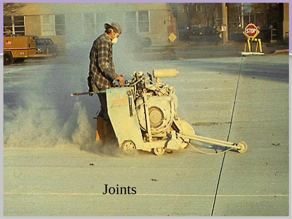
Joints

Saw Cuts 1/3 depth of 400 mm
(16 inch) thick airport pavement
R D Hooton U. of Toronto, TRB
Webinar May 25, 2016

Causes of Random Cracks near
saw-cut joints
ACI C504
R D Hooton U. of Toronto, TRB
Webinar May 25, 2016

Minimizing Cracks
a) Protect the fresh concrete from plastic shrinkage
cracking
b) Do not specify minimum cement contents that increase
unit water content of mixtures. Keep the concrete
sufficiently moist after set to lower early drying shrinkage
c) Minimize thermal cracking due to temperature gradients
(i.e. control heat evolution from concrete mixture & protect
from cold temperatures or from the hot sun)
d) Proper timing and depth of joints
R D Hooton U. of Toronto, TRB
Webinar May 25, 2016

TRB – Minimizing Cracking Prepared by Jason Weiss, [email protected] Slide 1 of 24
Reducing Shrinkage Cracking: Materials, Testing, and Specification
Jason Weiss, Oregon State University
765-412-8358

TRB – Minimizing Cracking Prepared by Jason Weiss, [email protected] Slide 2 of 24
Motivation
• Transverse cracking in 100,000+ bridges
• 62% of DOT’s consider cracking as a problem
• Cracks shorten service life, increase maintenance cost, and accelerate corrosion
Photo
htt
p:/
/ww
w.a
ggre
gate
researc
h.c
om
/caf/file
/new
deckcra
ckin
g.p
df
Here we see cracks spaced at 0.8 m
On the approaches to a bridge

TRB – Minimizing Cracking Prepared by Jason Weiss, [email protected] Slide 3 of 24
Reality is a Bit More Complex

TRB – Minimizing Cracking Prepared by Jason Weiss, [email protected] Slide 4 of 24
Outline
• Materials Approaches to Reduce Cracking
– Aggregate Volume
– Shrinkage Reducing Admixtures
– Internal Curing
• Tests to Evaluate Shrinkage and Cracking
– New Shrinkage Tests
– Dual Ring Test Has Merit and is Fast
• Performance Based Specifications
– Model Based on Risk of Cracking

TRB – Minimizing Cracking Prepared by Jason Weiss, [email protected] Slide 5 of 24
• Shrinkage - Volumetric Change Associated With A Loss Of Water
Concrete
• Shrinkage - Volumetric Change Associated With A Loss Of Water
• Measure Length Change in Concrete
• Shrinkage - Volumetric Change Associated With A Loss Of Water
• Aggregate Generally Does Not Shrink (In the US)
• It’s the Paste That Shrinks
Shrinkage of Concrete Constituents
Me
as
ure
d S
hri
nk
ag
e
Drying Time
Aggregate (Generally)
Paste

TRB – Minimizing Cracking Prepared by Jason Weiss, [email protected] Slide 6 of 24
Shrinkage is a Paste Property
n
fAggPasteConcrete
fPastePastefAggAggConcrete
V
VV
)1(
0 20 40 60 80 100
Aggregate Volume (%)
0
20
40
60
80
100
Sh
rin
ka
ge
(%
of
Pas
te)
Typical
Concrete
Stiffer Aggregate More Effective
In Restraining Paste Shrinkage
n 1.2 to 1.7

TRB – Minimizing Cracking Prepared by Jason Weiss, [email protected] Slide 7 of 24
Shrinkage and Paste Volume

TRB – Minimizing Cracking Prepared by Jason Weiss, [email protected] Slide 8 of 24
Kelvin Young Laplace Theory
• Concrete is Made of Little Tiny Holes, Called Pores
• Size of the Pore Matters
• Pressure (pcap) is related to surface tension (g) and inversely related to radius of the meniscus that forms (r)
• Big Pores – Low Pressure, Low Shrinkage
• Water is a clingly material – High Shrinkage
rpcap
g cos2

TRB – Minimizing Cracking Prepared by Jason Weiss, [email protected] Slide 9 of 24
SRA and Surface Tension
• To reduce shrinkage we reduce pressure, this means we either… reduce surface tension
• 1983 – Japan
• 1997/99 – US
• US Product 1999
rpcap
g2

TRB – Minimizing Cracking Prepared by Jason Weiss, [email protected] Slide 10 of 24
Shrinkage Reducing Admixtures

TRB – Minimizing Cracking Prepared by Jason Weiss, [email protected] Slide 11 of 24
Internal Curing Approach
• To reduce shrinkage we reduce pressure, we can increase the size of the pore
rpcap
g2

TRB – Minimizing Cracking Prepared by Jason Weiss, [email protected] Slide 12 of 24
Shrinkage Cracking and IC
• Restrained tests results on IC concrete (explained in more detail later)
• Increasing the use of LWA leads to a great reduction in cracking
• 24% LWA is typ. des.

TRB – Minimizing Cracking Prepared by Jason Weiss, [email protected] Slide 13 of 24
Field Trials and Applications
• Becoming More Widely Used • INDOT, NYDOT, IL Tollway
Cities and Towns, Others • Reducing Cracking

TRB – Minimizing Cracking Prepared by Jason Weiss, [email protected] Slide 14 of 24
Outline
• Materials Approaches to Reduce Cracking
– Aggregate Volume
– Shrinkage Reducing Admixtures
– Internal Curing
• Tests to Evaluate Shrinkage and Cracking
– New Shrinkage Tests
– Dual Ring Test Has Merit and is Fast
• Performance Based Specifications
– Model Based on Risk of Cracking

TRB – Minimizing Cracking Prepared by Jason Weiss, [email protected] Slide 15 of 24
Laboratory Tests to Measure Shrinkage
• ASTM C-157
• ASTM C-341 Time after Drying (Days)
Me
as
ure
d S
hri
nk
ag
e
Measured
Shrinkage
0l
l

TRB – Minimizing Cracking Prepared by Jason Weiss, [email protected] Slide 16 of 24
Measured
Shrinkage
Time (Days)
Ac
tua
l S
hri
nk
ag
e
Measured
Shrinkage
Time (Days)
Ac
tua
l S
hri
nk
ag
e
Measuring Shrinkage Starting Time is Critical
0.30 0.40 0.50 0.60 0.70
Water to Cement Ratio
0
250
500
750
1000
Sh
rin
ka
ge
Str
ain
(mm
/mm
x1
0^
-6)
Constant Aggregate Volume (70%)
0.30 0.40 0.50 0.60 0.70
Water to Cement Ratio
0
250
500
Sh
rin
ka
ge
Str
ain
(mm
/mm
x1
0^
-6)
Constant Aggregate Volume (65%)
Autogenous Shrinkage at 24 Hours
Time (Days)
Actu
al S
hri
nka
ge
Time (Days)
Actu
al S
hri
nkag
e
New Test – ASTM C1698

TRB – Minimizing Cracking Prepared by Jason Weiss, [email protected] Slide 17 of 24
Stress Development Approach
Original Ring
• Using an
Instrumented Ring
0 10 20 30 Time (Days)
-200
0
Ste
el
Str
ain
(m)
-100
Measured Strain
• Using an
Instrumented Ring
• Measure Strain
that Develops in
Steel
Pres
Determine Pressure
• Using an
Instrumented Ring
• Measure Strain
that Develops in
Steel
• Determine the
Pressure Required
to Obtain that
Strain
Pres
Obtain Stress
• Using an
Instrumented Ring
• Measure Strain
that Develops in
Steel
• Determine the
Pressure Required
to Obtain that
Strain
• Apply Pressure to
Concrete and
Obtain Tensile
Stress
22
22
2
22
2 ICOC
ICOC
OS
ISOSSSteelRrConcrete
RR
RR
R
RREtt
IC
Hossain and Weiss, 2003

TRB – Minimizing Cracking Prepared by Jason Weiss, [email protected] Slide 18 of 24
The Dual Ring Test

TRB – Minimizing Cracking Prepared by Jason Weiss, [email protected] Slide 19 of 24
Outline
• Materials Approaches to Reduce Cracking
– Aggregate Volume
– Shrinkage Reducing Admixtures
– Internal Curing
• Tests to Evaluate Shrinkage and Cracking
– New Shrinkage Tests
– Dual Ring Test Has Merit and is Fast
• Performance Based Specifications
– Model Based on Risk of Cracking

TRB – Minimizing Cracking Prepared by Jason Weiss, [email protected] Slide 20 of 24
Including ‘Random Variation’

TRB – Minimizing Cracking Prepared by Jason Weiss, [email protected] Slide 21 of 24
Results Of An Alternative Approach to Consider Variability in Shrinkage
• Plotted the percentage of specimens cracked by a specific age
• Results of 10,000 simulations
• Can quantify risk or total probability
0 14 28 42 56 70
Age of the Specimen (Days)
0
20
40
60
80
100
Sp
ec
ime
ns
Cra
ck
ed
(%
)
Age of Cracking
Deterministic
Age of Cracking
5% Probability
PCRACK

TRB – Minimizing Cracking Prepared by Jason Weiss, [email protected] Slide 22 of 24
Toward a Shrinkage Specification
200 400 600 800 1000
Shrinkage [m]
0
10
20
30
40
50
60
70
80
90
100
Pro
ba
bil
ity
of
Cra
ck
ing
[%
]
Base
Fast
Slow
DOR=60%
50%
20%
5%
Grade 2
Grade 3
Grade 1
Grade 4
200 400 600 800 1000
Shrinkage [m]
0
10
20
30
40
50
60
70
80
90
100
Pro
ba
bil
ity
of
Cra
ck
ing
[%
]
Base
Fast
Slow
DOR=100%
50%
20%
5%
Grade 2
Grade 3
Grade 1
Grade 4
• Shrinkage can be related to cracking potential and this simple approach begins to relate a simple test to performance

TRB – Minimizing Cracking Prepared by Jason Weiss, [email protected] Slide 23 of 24
A Summary of Thoughts
• Concrete Shrinks but We Have Three Defenses
– Aggregate Volume – Change Shrinking Proportion
– Shrinkage Reducing Admixtures – Change Fluid
– Internal Curing – Change Pore Emptying
• Current Tests are Lacking However
– New Tests Exists – 4+ New Shrinkage Tests
– Dual Ring Test Has Merit and is Fast
• Specifications can Be Performance Based
– Model Based on Risk of Cracking

TRB – Minimizing Cracking Prepared by Jason Weiss, [email protected] Slide 24 of 24
Thank you Are There Any Questions
Jason Weiss , Edwards Distinguished Professor

Donald Streeter, P.E.

Concrete Problems American’s spend 4.2 billion hours a year
stuck in traffic Bridges (>25%) are structurally deficient or
functionally obsolete Highways (>33%) are in poor
or mediocre condition ASCE 2013 report D+ Colbert Report
“Tiny Triumphs”

Constraints Maintenance / preservation vs. Reconstruction ? Accelerated construction / traffic demands ? Durability / Service life expectations ?
Band-aid fix Moderate service extension Longer term service
What is your goal??? How will you achieve your goal???

Cracking - Design Flexure
simple vs. continuous span length
Beam type Geometry, skew

Cracking - Materials Materials
water demand / characteristics Mixtures
interactions

Cracking - Construction Construction
Time of placement, environmental conditions Rate of placement Curing
timing, duration

Where do we see cracking Large elements / Mass placements Accelerated construction Multi-span continuous decks Large surface areas / flatwork Long / thin placements
Causes Shrinkage, Autogenous, Thermal Result of: design, materials, batching, environment,
placing, finishing, curing


Performance specification Owner defined parameters
Life cycle analysis Consider permeability, strength, cracking
QC Plan Contractor defines
process, materials, mixtures crack repair / treatment plan Maintenance schedule

Mass Concrete Treating more placements as “Mass”

Mass Concrete Means to minimize cracking:
• Mixture design • High pozzolan content
30% – 70% SCM’s
• Low heat cements
• Placement size / shape

Mass Concrete Means to minimize cracking (con’t):
• Cooling methods Plastic PCC temp
Internal cooling • Environmental “controls” Temperature monitoring
Max temp 160F Max temp differential 35F

Mass Concrete Thermal Control Plan requirements
Mixture dependant changes in mix = new TCP development
Method / duration of curing Thermal development analysis Temperature monitoring
sensor type / locations Monitoring system plan / recording / reporting
Corrective action plan to control temp

Accelerated Concrete Precast / accelerated closures CIP accelerated PCC
Shrinkage requirements Use longest set period allowed by work schedule

Superstructures HPC initiative in 1990’s
Placing under improved environmental controls Mix controls – strength, temps, etc… Immediate wet curing – 30 minutes from placement Extended wet curing – 14 days
Internal curing
Use of l-w fine aggregates as a replacement for sand 30% substitution by volume

IC Specification - construction Stockpile establishment SSD condition –
minimum 15% absorbed moisture presoak minimum of 48 hours Requires additional bin
Handling, delivery, placement - Follows traditional practice Similar characteristics

I-87 / Route 9 and Trout Brook

Comparison – I-87 7 day 14 day 28 day 28 day RCP F/T
Compressive Compressive Compressive Tensile
Strength Strength Strength Strength
Concrete Type
(psi)
(psi)
(psi)
(psi)
Coulombs
% loss
HPC 4420 5215 5910 569 1000 1.0
HPC-IC 4590 5790 6750 672 383 1.1
% Improvement 3.8% 11.0% 14.2%
Cracking – no transverse cracking, map cracking SB Barriers – used HPC NB, HPC-IC SB, both show cracking

Geometry Large surface areas
Construction practices Long – thin placements
SRA’s Fibers

Minimizing cracking Consider design:
Size, geometry, staging Materials selection to:
Minimize shrinkage, manage temps Construction practices:
Placement times Environmental conditions Placement, finishing, curing Protections during / after curing
No 2 days of placement are the same!