Embed Size (px)
Citation preview
Waste Water, Condensate and HeatTransfer Fluid Pump
MK
Type Series Booklet

Legal information/Copyright
Type Series Booklet MK
All rights reserved. The contents provided herein must neither be distributed, copied, reproduced,edited or processed for any other purpose, nor otherwise transmitted, published or made available to athird party without the manufacturer's express written consent.
Subject to technical modification without prior notice.
© KSB SE & Co. KGaA, Frankenthal 19/06/2019
Contents
Drainage Pumps / Waste Water Pumps .......................................................................................................... 4Waste Water Pumps / Condensate Pumps / Heat Transfer Fluid Pumps ................................................................................. 4
MK......................................................................................................................................................................................... 4Main applications........................................................................................................................................................... 4Fluids handled ................................................................................................................................................................ 4Operating data............................................................................................................................................................... 4Design details ................................................................................................................................................................. 4Designation .................................................................................................................................................................... 5Materials ......................................................................................................................................................................... 5Product benefits ............................................................................................................................................................. 5Product information ...................................................................................................................................................... 5
Product information as per Regulation No. 1907/2006 (REACH) .......................................................................... 5Selection tables .............................................................................................................................................................. 6Technical data ................................................................................................................................................................ 7
MK, MKA variants without motor .......................................................................................................................... 7MK-B, MKA-B variants without motor.................................................................................................................... 7MK-C, MKA-C variants without motor.................................................................................................................... 7MKY variant without motor.................................................................................................................................... 8Motors....................................................................................................................................................................... 8
Characteristic curves....................................................................................................................................................... 9n = 2900 rpm ............................................................................................................................................................ 9
MK/MKA 20-3, 20-4, 20-5, 20-6; n = 2900 rpm ................................................................................................. 9MKY 20-3, 20-4, 20-5, 20-6; n = 2900 rpm ...................................................................................................... 10
n = 1450 rpm .......................................................................................................................................................... 11MK/MKA 20-1, 20-2; n = 1450 rpm.................................................................................................................. 11MKY 20-1, 20-2; n = 1450 rpm......................................................................................................................... 12
Dimensions ................................................................................................................................................................... 13MK/MKA ................................................................................................................................................................. 13MKY ........................................................................................................................................................................ 14
Accessories .................................................................................................................................................................... 15Lubrication equipment (optional)......................................................................................................................... 15Pump accessories .................................................................................................................................................... 15Float switch............................................................................................................................................................. 15Control units and switchgear ................................................................................................................................ 16Alarm switchgears for pumps without ATEX ....................................................................................................... 17LevelControl Basic 2 ............................................................................................................................................... 17Control unit/switchgear accessories ...................................................................................................................... 18
General assembly drawings/exploded views with list of components...................................................................... 18MK, MKA ................................................................................................................................................................ 18MK, MKA - grease-lubricated................................................................................................................................ 19MK, MKA - internally lubricated by fluid handled............................................................................................... 20MK, MKA - lubricated by an external fluid .......................................................................................................... 21MKY ........................................................................................................................................................................ 22
Contents
3
Drainage Pumps / Waste Water PumpsWaste Water Pumps / Condensate Pumps / Heat Transfer Fluid Pumps
4 MK
Drainage Pumps / Waste Water Pumps
Waste Water Pumps / Condensate Pumps / HeatTransfer Fluid Pumps
MK
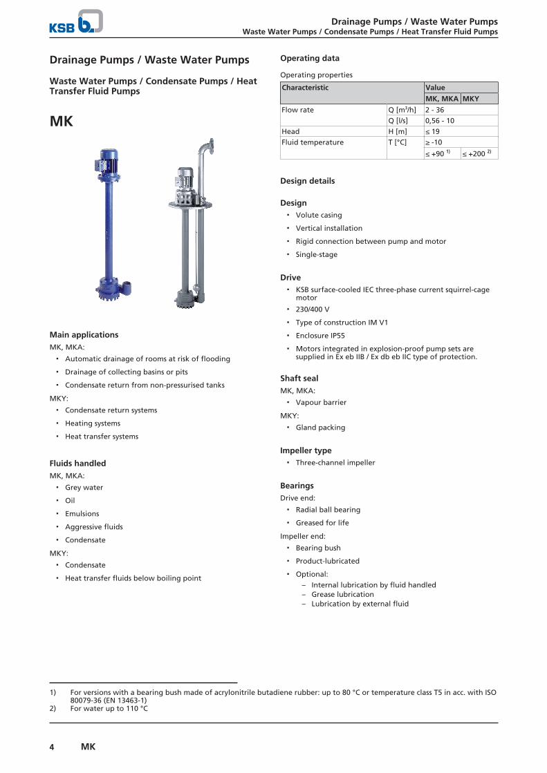
Main applicationsMK, MKA:
▪ Automatic drainage of rooms at risk of flooding
▪ Drainage of collecting basins or pits
▪ Condensate return from non-pressurised tanks
MKY:
▪ Condensate return systems
▪ Heating systems
▪ Heat transfer systems
Fluids handledMK, MKA:
▪ Grey water
▪ Oil
▪ Emulsions
▪ Aggressive fluids
▪ Condensate
MKY:
▪ Condensate
▪ Heat transfer fluids below boiling point
Operating data
Operating properties
Characteristic Value
MK, MKA MKY
Flow rate Q [m3/h] 2 - 36Q [l/s] 0,56 - 10
Head H [m] ≤ 19Fluid temperature T [°C] ≥ -10
≤ +90 1) ≤ +200 2)
Design details
Design▪ Volute casing
▪ Vertical installation
▪ Rigid connection between pump and motor
▪ Single-stage
Drive▪ KSB surface-cooled IEC three-phase current squirrel-cage
motor
▪ 230/400 V
▪ Type of construction IM V1
▪ Enclosure IP55
▪ Motors integrated in explosion-proof pump sets aresupplied in Ex eb IIB / Ex db eb IIC type of protection.
Shaft sealMK, MKA:
▪ Vapour barrier
MKY:
▪ Gland packing
Impeller type▪ Three-channel impeller
BearingsDrive end:
▪ Radial ball bearing
▪ Greased for life
Impeller end:
▪ Bearing bush
▪ Product-lubricated
▪ Optional:– Internal lubrication by fluid handled– Grease lubrication– Lubrication by external fluid
1) For versions with a bearing bush made of acrylonitrile butadiene rubber: up to 80 °C or temperature class T5 in acc. with ISO80079-36 (EN 13463-1)
2) For water up to 110 °C
Drainage Pumps / Waste Water PumpsWaste Water Pumps / Condensate Pumps / Heat Transfer Fluid Pumps
5MK
Explosion protectionMK, MKA:
▪ Available
▪ For explosion-proof variants one of the optionallubrication types must be used for the bearing bush.
MKY:
▪ Not available
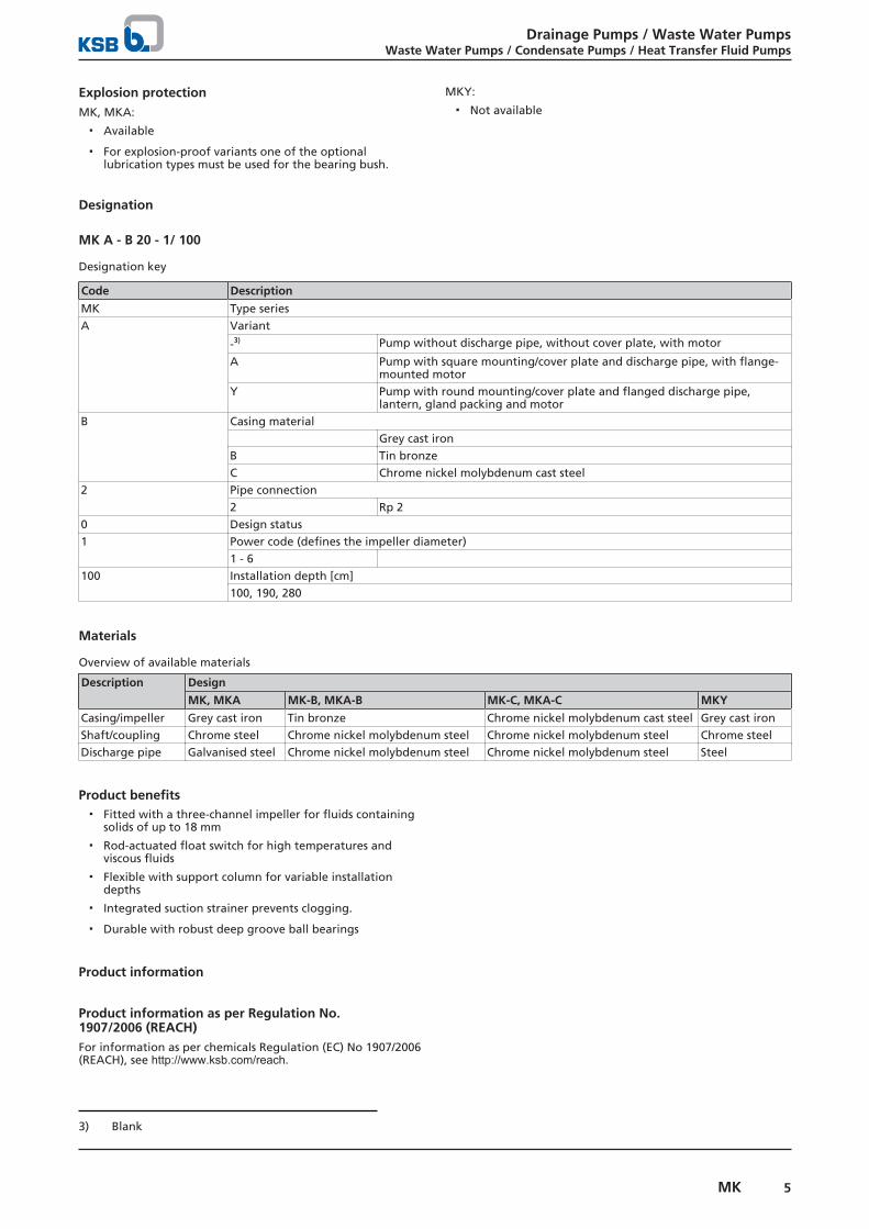
Designation
MK A - B 20 - 1/ 100
Designation key
Code Description
MK Type seriesA Variant
-3) Pump without discharge pipe, without cover plate, with motor
A Pump with square mounting/cover plate and discharge pipe, with flange-mounted motor
Y Pump with round mounting/cover plate and flanged discharge pipe,lantern, gland packing and motor
B Casing materialGrey cast iron
B Tin bronzeC Chrome nickel molybdenum cast steel
2 Pipe connection2 Rp 2
0 Design status1 Power code (defines the impeller diameter)
1 - 6100 Installation depth [cm]
100, 190, 280
Materials
Overview of available materials
Description Design
MK, MKA MK-B, MKA-B MK-C, MKA-C MKY
Casing/impeller Grey cast iron Tin bronze Chrome nickel molybdenum cast steel Grey cast ironShaft/coupling Chrome steel Chrome nickel molybdenum steel Chrome nickel molybdenum steel Chrome steelDischarge pipe Galvanised steel Chrome nickel molybdenum steel Chrome nickel molybdenum steel Steel
Product benefits▪ Fitted with a three-channel impeller for fluids containing
solids of up to 18 mm
▪ Rod-actuated float switch for high temperatures andviscous fluids
▪ Flexible with support column for variable installationdepths
▪ Integrated suction strainer prevents clogging.
▪ Durable with robust deep groove ball bearings
Product information
Product information as per Regulation No.1907/2006 (REACH)For information as per chemicals Regulation (EC) No 1907/2006(REACH), see http://www.ksb.com/reach.
3) Blank
Drainage Pumps / Waste Water PumpsWaste Water Pumps / Condensate Pumps / Heat Transfer Fluid Pumps
6 MK
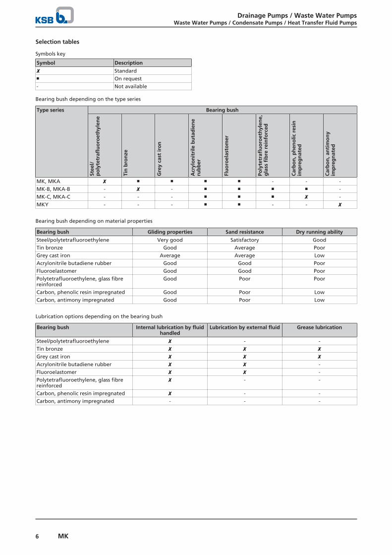
Selection tables
Symbols key
Symbol Description
✘ Standard■ On request- Not available
Bearing bush depending on the type series
Type series Bearing bush
Stee
l/p
oly
tetr
aflu
oro
eth
ylen
e
Tin
bro
nze
Gre
y ca
st ir
on
Acr
ylo
nit
rile
bu
tad
ien
eru
bb
er
Flu
oro
elas
tom
er
Poly
tetr
aflu
oro
eth
ylen
e,g
lass
fib
re r
ein
forc
ed
Car
bo
n, p
hen
olic
res
inim
pre
gn
ated
Car
bo
n, a
nti
mo
ny
imp
reg
nat
ed
MK, MKA ✘ ■ ■ ■ ■ - - -MK-B, MKA-B - ✘ - ■ ■ ■ ■ -MK-C, MKA-C - - - ■ ■ ■ ✘ -MKY - - - ■ ■ - - ✘
Bearing bush depending on material properties
Bearing bush Gliding properties Sand resistance Dry running ability
Steel/polytetrafluoroethylene Very good Satisfactory GoodTin bronze Good Average PoorGrey cast iron Average Average LowAcrylonitrile butadiene rubber Good Good PoorFluoroelastomer Good Good PoorPolytetrafluoroethylene, glass fibrereinforced
Good Poor Poor
Carbon, phenolic resin impregnated Good Poor LowCarbon, antimony impregnated Good Poor Low
Lubrication options depending on the bearing bush
Bearing bush Internal lubrication by fluidhandled
Lubrication by external fluid Grease lubrication
Steel/polytetrafluoroethylene ✘ - -Tin bronze ✘ ✘ ✘Grey cast iron ✘ ✘ ✘Acrylonitrile butadiene rubber ✘ ✘ -Fluoroelastomer ✘ ✘ -Polytetrafluoroethylene, glass fibrereinforced
✘ - -
Carbon, phenolic resin impregnated ✘ - -Carbon, antimony impregnated - - -
Drainage Pumps / Waste Water PumpsWaste Water Pumps / Condensate Pumps / Heat Transfer Fluid Pumps
7MK
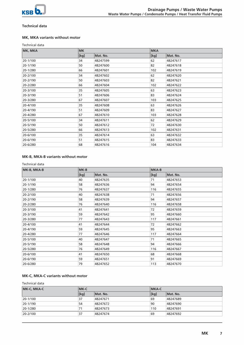
Technical data
MK, MKA variants without motor
Technical data
MK, MKA MK MKA
[kg] Mat. No. [kg] Mat. No.
20-1/100 34 48247599 62 4824761720-1/190 50 48247600 82 4824761820-1/280 66 48247601 102 48247619
20-2/100 34 48247602 62 4824762020-2/190 50 48247603 82 4824762120-2/280 66 48247604 102 48247622
20-3/100 35 48247605 63 4824762320-3/190 51 48247606 83 4824762420-3/280 67 48247607 103 48247625
20-4/100 35 48247608 63 4824762620-4/190 51 48247609 83 4824762720-4/280 67 48247610 103 48247628
20-5/100 34 48247611 62 4824762920-5/190 50 48247612 72 4824763020-5/280 66 48247613 102 48247631
20-6/100 35 48247614 63 4824763220-6/190 51 48247615 83 4824763320-6/280 68 48247616 104 48247634
MK-B, MKA-B variants without motor
Technical data
MK-B, MKA-B MK-B MKA-B
[kg] Mat. No. [kg] Mat. No.
20-1/100 40 48247635 71 4824765320-1/190 58 48247636 94 4824765420-1/280 76 48247637 116 48247655
20-2/100 40 48247638 71 4824765620-2/190 58 48247639 94 4824765720-2/280 76 48247640 116 48247658
20-3/100 41 48247641 72 4824765920-3/190 59 48247642 95 4824766020-3/280 77 48247643 117 48247661
20-4/100 41 48247644 72 4824766220-4/190 59 48247645 95 4824766320-4/280 77 48247646 117 48247664
20-5/100 40 48247647 71 4824766520-5/190 58 48247648 94 4824766620-5/280 76 48247649 116 48247667
20-6/100 41 48247650 68 4824766820-6/190 59 48247651 91 4824766920-6/280 79 48247652 113 48247670
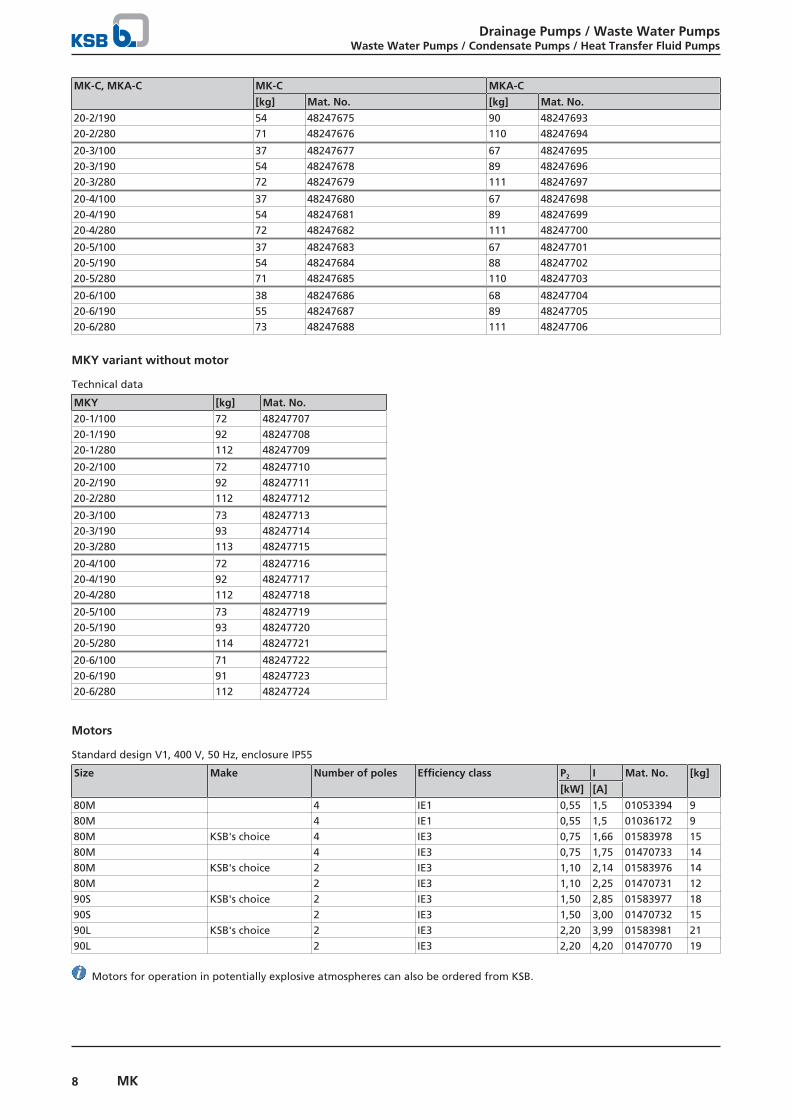
MK-C, MKA-C variants without motor
Technical data
MK-C, MKA-C MK-C MKA-C
[kg] Mat. No. [kg] Mat. No.
20-1/100 37 48247671 69 4824768920-1/190 54 48247672 90 4824769020-1/280 71 48247673 110 48247691
20-2/100 37 48247674 69 48247692
Drainage Pumps / Waste Water PumpsWaste Water Pumps / Condensate Pumps / Heat Transfer Fluid Pumps
8 MK
MK-C, MKA-C MK-C MKA-C
[kg] Mat. No. [kg] Mat. No.
20-2/190 54 48247675 90 4824769320-2/280 71 48247676 110 48247694
20-3/100 37 48247677 67 4824769520-3/190 54 48247678 89 4824769620-3/280 72 48247679 111 48247697
20-4/100 37 48247680 67 4824769820-4/190 54 48247681 89 4824769920-4/280 72 48247682 111 48247700
20-5/100 37 48247683 67 4824770120-5/190 54 48247684 88 4824770220-5/280 71 48247685 110 48247703
20-6/100 38 48247686 68 4824770420-6/190 55 48247687 89 4824770520-6/280 73 48247688 111 48247706
MKY variant without motor
Technical data
MKY [kg] Mat. No.
20-1/100 72 4824770720-1/190 92 4824770820-1/280 112 48247709
20-2/100 72 4824771020-2/190 92 4824771120-2/280 112 48247712
20-3/100 73 4824771320-3/190 93 4824771420-3/280 113 48247715
20-4/100 72 4824771620-4/190 92 4824771720-4/280 112 48247718
20-5/100 73 4824771920-5/190 93 4824772020-5/280 114 48247721
20-6/100 71 4824772220-6/190 91 4824772320-6/280 112 48247724
Motors
Standard design V1, 400 V, 50 Hz, enclosure IP55
Size Make Number of poles Efficiency class P2 I Mat. No. [kg]
[kW] [A]
80M 4 IE1 0,55 1,5 01053394 980M 4 IE1 0,55 1,5 01036172 980M KSB's choice 4 IE3 0,75 1,66 01583978 1580M 4 IE3 0,75 1,75 01470733 1480M KSB's choice 2 IE3 1,10 2,14 01583976 1480M 2 IE3 1,10 2,25 01470731 1290S KSB's choice 2 IE3 1,50 2,85 01583977 1890S 2 IE3 1,50 3,00 01470732 1590L KSB's choice 2 IE3 2,20 3,99 01583981 2190L 2 IE3 2,20 4,20 01470770 19
Motors for operation in potentially explosive atmospheres can also be ordered from KSB.
Drainage Pumps / Waste Water PumpsWaste Water Pumps / Condensate Pumps / Heat Transfer Fluid Pumps
9MK
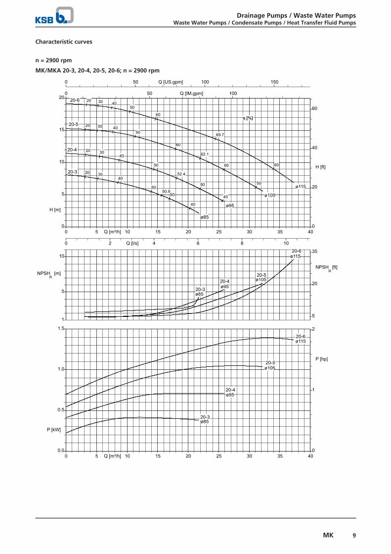
Characteristic curves
n = 2900 rpm
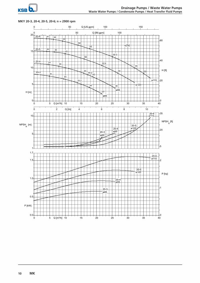
MK/MKA 20-3, 20-4, 20-5, 20-6; n = 2900 rpm
0 5 10 15 20 25 30 35 40Q [m³/h]
0 50 100 150Q [US.gpm]
0 50 100Q [IM.gpm]
0
5
10
15
20
H [m]
0
20
40
60
H [ft]
0 2 4 6 8 10Q [l/s]
5
10
1
NPSHR
[m]
20
5
35
NPSHR [ft]
0.0
0.5
1.0
1.5
P [kW]
0
1
2
P [hp]
0 5 10 15 20 25 30 35 40Q [m³/h]
ø85
ø85
ø85
50.9
20 3040
40
50
50
η [%]
20-3
20-3
20-3
ø95
ø95
ø95
52.4
20 3040
40
50
50
20-4
20-4
20-4
ø105
ø105
ø105
62.1
20 30 4050
50
60
60
20-5
20-5
20-5
ø115
ø115
ø115
69.7
20 30 4050
60
60
20-6
20-6
20-6
Drainage Pumps / Waste Water PumpsWaste Water Pumps / Condensate Pumps / Heat Transfer Fluid Pumps
10 MK
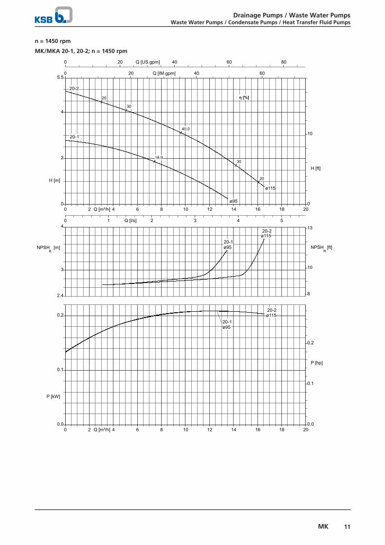
MKY 20-3, 20-4, 20-5, 20-6; n = 2900 rpm
0 5 10 15 20 25 30 35 40Q [m³/h]
0 50 100 150Q [US.gpm]
0 50 100Q [IM.gpm]
0
5
10
15
20
H [m]
0
20
40
60
H [ft]
0 2 4 6 8 10Q [l/s]
5
10
1
NPSHR
[m]
20
5
35
NPSHR [ft]
0.0
0.5
1.0
1.5
1.7
P [kW]
0
1
2
P [hp]
0 5 10 15 20 25 30 35 40Q [m³/h]
ø85
ø85
ø85
33.2
20
20
30
30
η [%]
20-3
20-3
20-3
ø95
ø95
ø95
40.2
2030
30
4040
20-4
20-4
20-4
ø105
ø105
ø105
52.6
20 3040
50
50
20-5
20-5
20-5
ø115
ø115
ø115
59.0
20 3040
50
50
55
55
20-6
20-6
20-6
Drainage Pumps / Waste Water PumpsWaste Water Pumps / Condensate Pumps / Heat Transfer Fluid Pumps
11MK
n = 1450 rpm
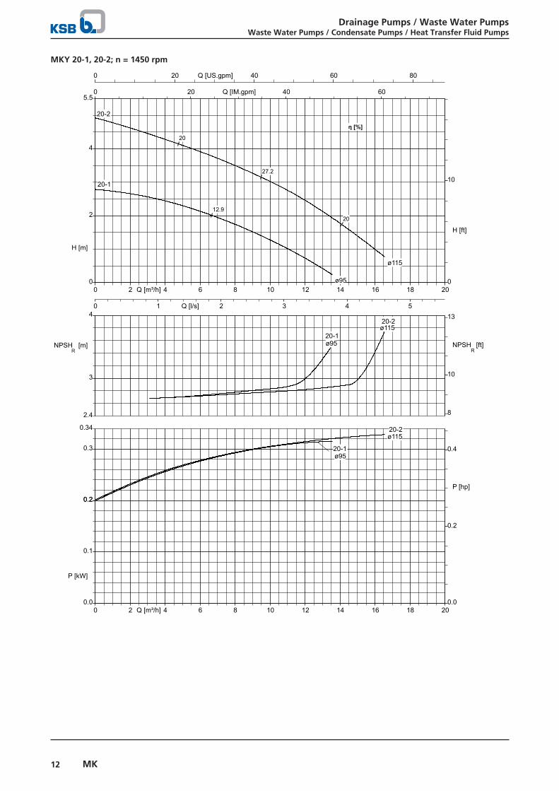
MK/MKA 20-1, 20-2; n = 1450 rpm
0 2 4 6 8 10 12 14 16 18 20Q [m³/h]
0 20 40 60 80Q [US.gpm]
0 20 40 60Q [IM.gpm]
0
2
4
5.5
H [m]
0
10
H [ft]
0 1 2 3 4 5Q [l/s]
3
4
2.4
NPSHR
[m]
10
8
13
NPSHR [ft]
0.0
0.1
0.2
P [kW]
0.0
0.1
0.2
P [hp]
0 2 4 6 8 10 12 14 16 18 20Q [m³/h]
ø95
ø95
ø95
18.9
η [%]
20-1
20-1
20-1
ø115
ø115
ø115
40.0
20
20
30
30
η [%]
20-2
20-2
20-2
Drainage Pumps / Waste Water PumpsWaste Water Pumps / Condensate Pumps / Heat Transfer Fluid Pumps
12 MK
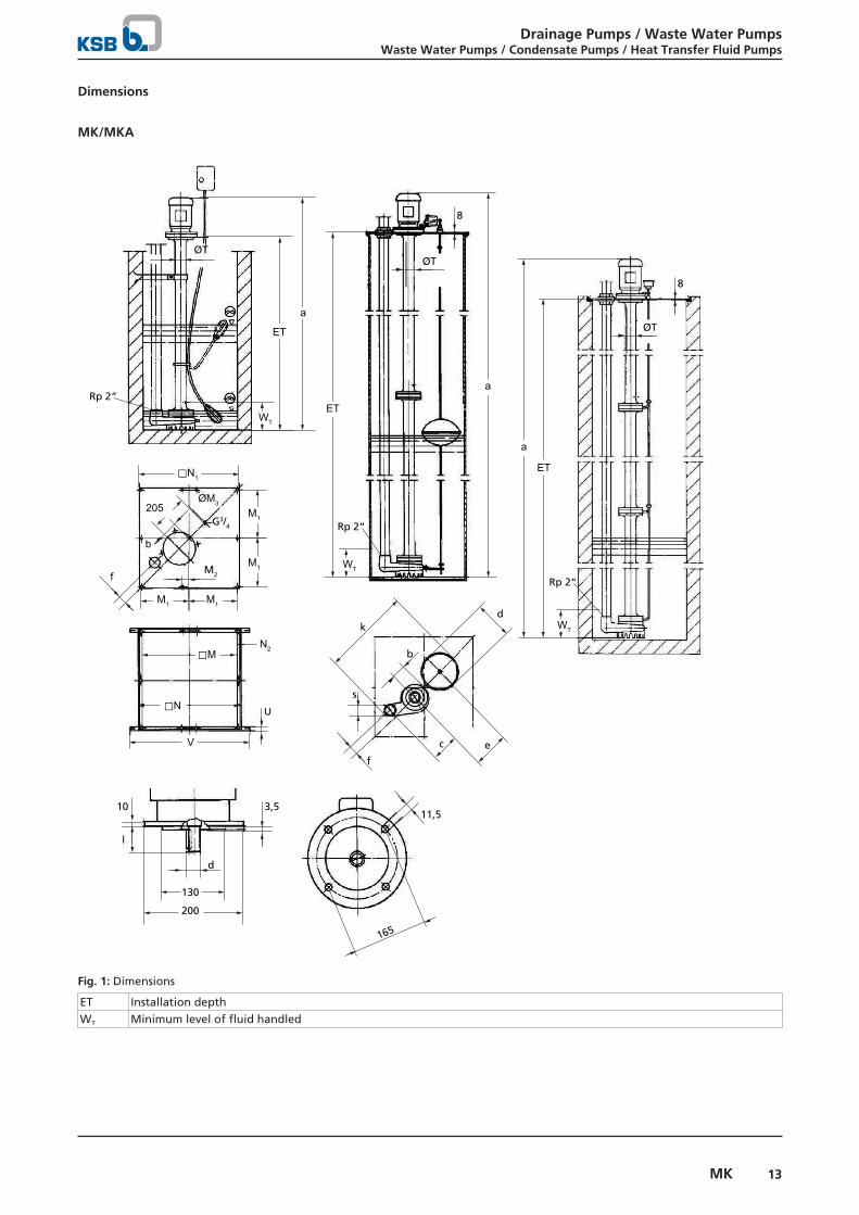
MKY 20-1, 20-2; n = 1450 rpm
0 2 4 6 8 10 12 14 16 18 20Q [m³/h]
0 20 40 60 80Q [US.gpm]
0 20 40 60Q [IM.gpm]
0
2
4
5.5
H [m]
0
10
H [ft]
0 1 2 3 4 5Q [l/s]
3
4
2.4
NPSHR
[m]
10
8
13
NPSHR [ft]
0.0
0.1
0.2
0.3
0.34
P [kW]
0.0
0.2
0.4
P [hp]
0 2 4 6 8 10 12 14 16 18 20Q [m³/h]
0.2
ø95
ø95
ø95
12.9
η [%]
20-1
20-1
20-1
ø115
ø115
ø115
27.2
20
20
20-2
20-2
20-2
Drainage Pumps / Waste Water PumpsWaste Water Pumps / Condensate Pumps / Heat Transfer Fluid Pumps
13MK
Dimensions
MK/MKA
ET
a
M1
M1
M1 M1
⃞N1
ØT
M2f
G3/4
ØM3
b
205
N2
U
⃞M
⃞N
V
ØT
8
ØT
8
a
a
ET
200
130
d
11,5
165
l
3,510
f
b
s
kd
e
WTET
WT
WT
Rp 2“
Rp 2“
Rp 2“
c
Fig. 1: Dimensions
ET Installation depthWT Minimum level of fluid handled
Drainage Pumps / Waste Water PumpsWaste Water Pumps / Condensate Pumps / Heat Transfer Fluid Pumps
14 MK
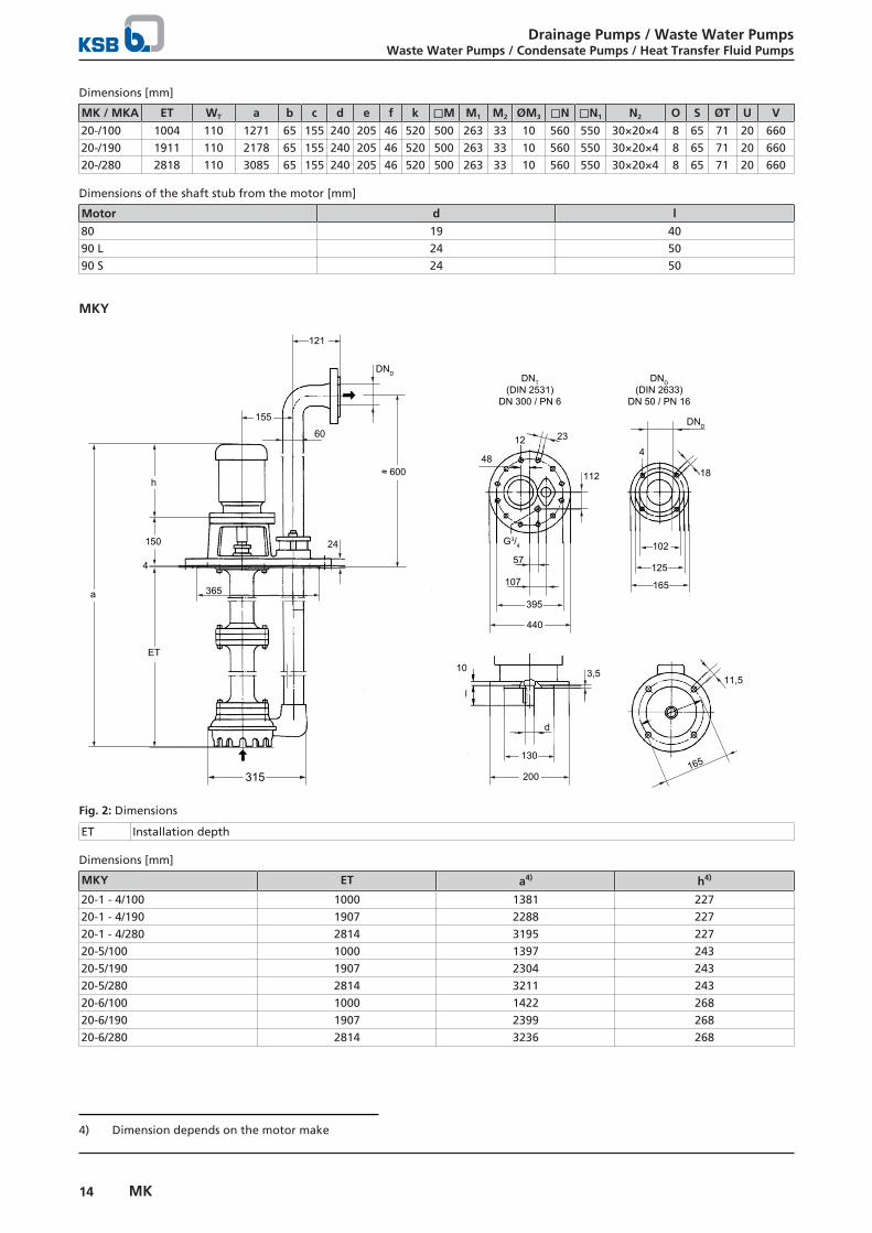
Dimensions [mm]
MK / MKA ET WT a b c d e f k ⃞M M1 M2 ØM3 ⃞N ⃞N1 N2 O S ØT U V
20-/100 1004 110 1271 65 155 240 205 46 520 500 263 33 10 560 550 30×20×4 8 65 71 20 66020-/190 1911 110 2178 65 155 240 205 46 520 500 263 33 10 560 550 30×20×4 8 65 71 20 66020-/280 2818 110 3085 65 155 240 205 46 520 500 263 33 10 560 550 30×20×4 8 65 71 20 660
Dimensions of the shaft stub from the motor [mm]
Motor d l
80 19 4090 L 24 5090 S 24 50
MKY
h
4
DNT(DIN 2531)
DN 300 / PN 6
ET
150
365
24
DND
≈ 600
121
155
60
102
165
DND
125
a
200
130
d
11,5
165
G3/4
4
18
2312
440
395
57
107
10
l
48
112
3,5
DND(DIN 2633)
DN 50 / PN 16
315
Fig. 2: Dimensions
ET Installation depth
Dimensions [mm]
MKY ET a4) h4)
20-1 - 4/100 1000 1381 22720-1 - 4/190 1907 2288 22720-1 - 4/280 2814 3195 22720-5/100 1000 1397 24320-5/190 1907 2304 24320-5/280 2814 3211 24320-6/100 1000 1422 26820-6/190 1907 2399 26820-6/280 2814 3236 268
4) Dimension depends on the motor make
Drainage Pumps / Waste Water PumpsWaste Water Pumps / Condensate Pumps / Heat Transfer Fluid Pumps
15MK
Dimensions of the shaft stub from the motor [mm]
Motor d l
80 19 4090 L 24 5090 S 24 50
Accessories
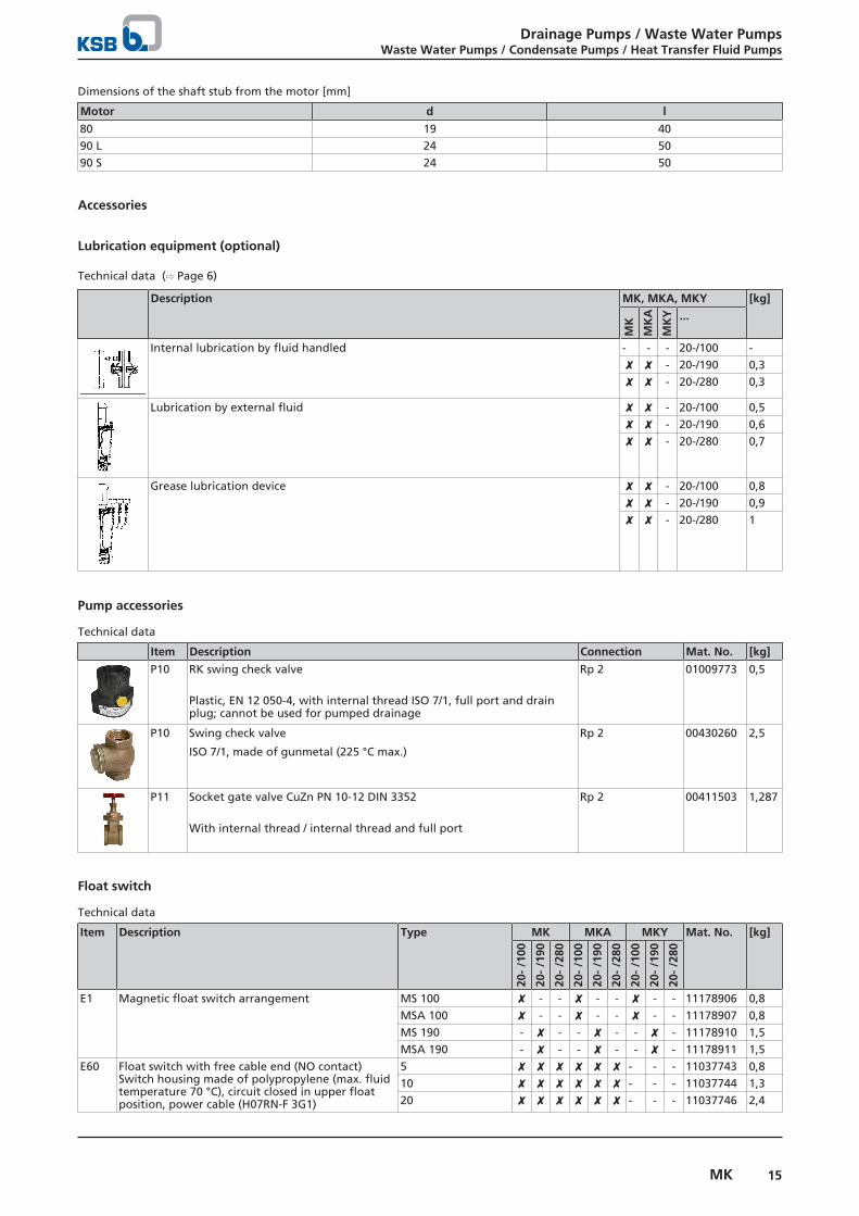
Lubrication equipment (optional)
Technical data (⇨ Page 6)
Description MK, MKA, MKY [kg]
MK
MK
A
MK
Y ...
Internal lubrication by fluid handled - - - 20-/100 -✘ ✘ - 20-/190 0,3✘ ✘ - 20-/280 0,3
Lubrication by external fluid ✘ ✘ - 20-/100 0,5✘ ✘ - 20-/190 0,6✘ ✘ - 20-/280 0,7
Grease lubrication device ✘ ✘ - 20-/100 0,8✘ ✘ - 20-/190 0,9✘ ✘ - 20-/280 1
Pump accessories
Technical data
Item Description Connection Mat. No. [kg]
P10 RK swing check valve
Plastic, EN 12 050-4, with internal thread ISO 7/1, full port and drainplug; cannot be used for pumped drainage
Rp 2 01009773 0,5
P10 Swing check valve
ISO 7/1, made of gunmetal (225 °C max.)
Rp 2 00430260 2,5
P11 Socket gate valve CuZn PN 10-12 DIN 3352
With internal thread / internal thread and full port
Rp 2 00411503 1,287
Float switch
Technical data
Item Description Type MK MKA MKY Mat. No. [kg]
20-
/100
20-
/190
20-
/280
20-
/100
20-
/190
20-
/280
20-
/100
20-
/190
20-
/280
E1 Magnetic float switch arrangement MS 100 ✘ - - ✘ - - ✘ - - 11178906 0,8MSA 100 ✘ - - ✘ - - ✘ - - 11178907 0,8MS 190 - ✘ - - ✘ - - ✘ - 11178910 1,5MSA 190 - ✘ - - ✘ - - ✘ - 11178911 1,5
E60 Float switch with free cable end (NO contact)Switch housing made of polypropylene (max. fluidtemperature 70 °C), circuit closed in upper floatposition, power cable (H07RN-F 3G1)
5 ✘ ✘ ✘ ✘ ✘ ✘ - - - 11037743 0,810 ✘ ✘ ✘ ✘ ✘ ✘ - - - 11037744 1,320 ✘ ✘ ✘ ✘ ✘ ✘ - - - 11037746 2,4
Drainage Pumps / Waste Water PumpsWaste Water Pumps / Condensate Pumps / Heat Transfer Fluid Pumps
16 MK
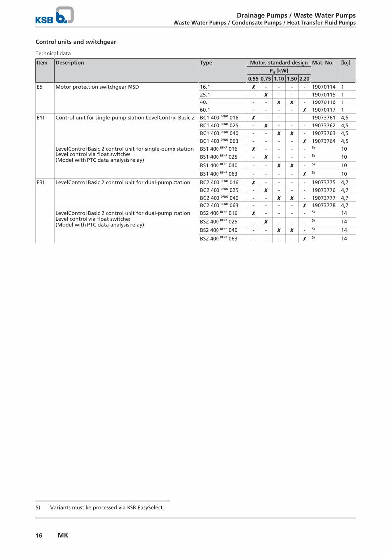
Control units and switchgear
Technical data
Item Description Type Motor, standard design Mat. No. [kg]
PN [kW]
0,55 0,75 1,10 1,50 2,20
E5 Motor protection switchgear MSD 16.1 ✘ - - - - 19070114 125.1 - ✘ - - - 19070115 140.1 - - ✘ ✘ - 19070116 160.1 - - - - ✘ 19070117 1
E11 Control unit for single-pump station LevelControl Basic 2 BC1 400 DFNO 016 ✘ - - - - 19073761 4,5BC1 400 DFNO 025 - ✘ - - - 19073762 4,5BC1 400 DFNO 040 - - ✘ ✘ - 19073763 4,5BC1 400 DFNO 063 - - - - ✘ 19073764 4,5
LevelControl Basic 2 control unit for single-pump stationLevel control via float switches(Model with PTC data analysis relay)
BS1 400 DFNP 016 ✘ - - - - 5) 10
BS1 400 DFNP 025 - ✘ - - - 5) 10
BS1 400 DFNP 040 - - ✘ ✘ - 5) 10
BS1 400 DFNP 063 - - - - ✘ 5) 10
E31 LevelControl Basic 2 control unit for dual-pump station BC2 400 DFNO 016 ✘ - - - - 19073775 4,7BC2 400 DFNO 025 - ✘ - - - 19073776 4,7BC2 400 DFNO 040 - - ✘ ✘ - 19073777 4,7BC2 400 DFNO 063 - - - - ✘ 19073778 4,7
LevelControl Basic 2 control unit for dual-pump stationLevel control via float switches(Model with PTC data analysis relay)
BS2 400 DFNP 016 ✘ - - - - 5) 14
BS2 400 DFNP 025 - ✘ - - - 5) 14
BS2 400 DFNP 040 - - ✘ ✘ - 5) 14
BS2 400 DFNP 063 - - - - ✘ 5) 14
5) Variants must be processed via KSB EasySelect.
Drainage Pumps / Waste Water PumpsWaste Water Pumps / Condensate Pumps / Heat Transfer Fluid Pumps
17MK
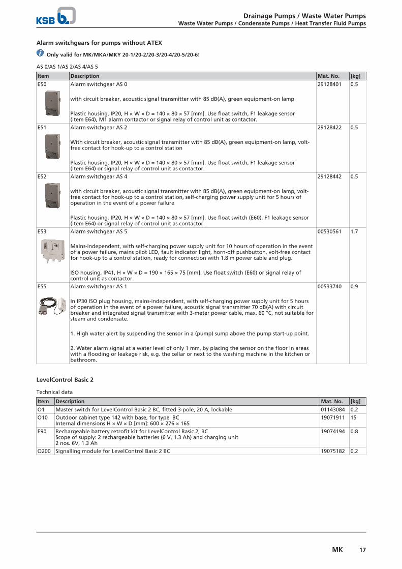
Alarm switchgears for pumps without ATEX
Only valid for MK/MKA/MKY 20-1/20-2/20-3/20-4/20-5/20-6!
AS 0/AS 1/AS 2/AS 4/AS 5
Item Description Mat. No. [kg]
E50 Alarm switchgear AS 0
with circuit breaker, acoustic signal transmitter with 85 dB(A), green equipment-on lamp
Plastic housing, IP20, H × W × D = 140 × 80 × 57 [mm]. Use float switch, F1 leakage sensor(item E64), M1 alarm contactor or signal relay of control unit as contactor.
29128401 0,5
E51 Alarm switchgear AS 2
With circuit breaker, acoustic signal transmitter with 85 dB(A), green equipment-on lamp, volt-free contact for hook-up to a control station
Plastic housing, IP20, H × W × D = 140 × 80 × 57 [mm]. Use float switch, F1 leakage sensor(item E64) or signal relay of control unit as contactor.
29128422 0,5
E52 Alarm switchgear AS 4
with circuit breaker, acoustic signal transmitter with 85 dB(A), green equipment-on lamp, volt-free contact for hook-up to a control station, self-charging power supply unit for 5 hours ofoperation in the event of a power failure
Plastic housing, IP20, H × W × D = 140 × 80 × 57 [mm]. Use float switch (E60), F1 leakage sensor(item E64) or signal relay of control unit as contactor.
29128442 0,5
E53 Alarm switchgear AS 5
Mains-independent, with self-charging power supply unit for 10 hours of operation in the eventof a power failure, mains pilot LED, fault indicator light, horn-off pushbutton, volt-free contactfor hook-up to a control station, ready for connection with 1.8 m power cable and plug.
ISO housing, IP41, H × W × D = 190 × 165 × 75 [mm]. Use float switch (E60) or signal relay ofcontrol unit as contactor.
00530561 1,7
E55 Alarm switchgear AS 1
In IP30 ISO plug housing, mains-independent, with self-charging power supply unit for 5 hoursof operation in the event of a power failure, acoustic signal transmitter 70 dB(A) with circuitbreaker and integrated signal transmitter with 3-meter power cable, max. 60 °C, not suitable forsteam and condensate.
1. High water alert by suspending the sensor in a (pump) sump above the pump start-up point.
2. Water alarm signal at a water level of only 1 mm, by placing the sensor on the floor in areaswith a flooding or leakage risk, e.g. the cellar or next to the washing machine in the kitchen orbathroom.
00533740 0,9
LevelControl Basic 2
Technical data
Item Description Mat. No. [kg]
O1 Master switch for LevelControl Basic 2 BC, fitted 3-pole, 20 A, lockable 01143084 0,2O10 Outdoor cabinet type 142 with base, for type BC
Internal dimensions H × W × D [mm]: 600 × 276 × 16519071911 15
E90 Rechargeable battery retrofit kit for LevelControl Basic 2, BCScope of supply: 2 rechargeable batteries (6 V, 1.3 Ah) and charging unit2 nos. 6V, 1.3 Ah
19074194 0,8
O200 Signalling module for LevelControl Basic 2 BC 19075182 0,2
Drainage Pumps / Waste Water PumpsWaste Water Pumps / Condensate Pumps / Heat Transfer Fluid Pumps
18 MK
Control unit/switchgear accessories
Technical data
Item Description Type Mat. No. [kg]
E64 F1 leakage sensorAs contactor for alarm switchgears AS 0, AS 2 or AS 4, with 3-metre power cable, max. 40 °C, notsuitable for steam and condensate.
19072366 0,2
E70 Horn, 12 V DC, 105 dB, 150 mA, IP54 01086547 0,1E71 Alarm combination (yellow alarm strobe light and piezo buzzer 92 dB), 12 V DC, 120 mA, IP65 01139930 0,1E72 Yellow alarm strobe light, 12 V DC, 195 mA, IP65 01056355 0,3O45 Plastic housing, IP65, for easier installation of alarm strobe light, for wall mounting 01061067 0,2
General assembly drawings/exploded views with list of components
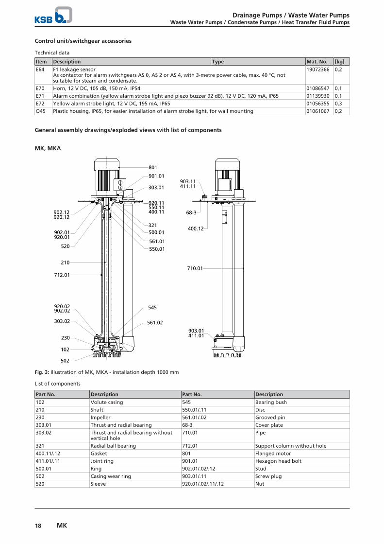
MK, MKA
920.11550.11400.11
710.01210
712.01
545920.02902.02
303.02 561.02
230
102
502
303.01
68-3
400.12902.01920.01
520
801
901.01903.11411.11
321
902.12920.12
500.01
561.01
550.01
903.01411.01
Fig. 3: Illustration of MK, MKA - installation depth 1000 mm
List of components
Part No. Description Part No. Description
102 Volute casing 545 Bearing bush210 Shaft 550.01/.11 Disc230 Impeller 561.01/.02 Grooved pin303.01 Thrust and radial bearing 68-3 Cover plate303.02 Thrust and radial bearing without
vertical hole710.01 Pipe
321 Radial ball bearing 712.01 Support column without hole400.11/.12 Gasket 801 Flanged motor411.01/.11 Joint ring 901.01 Hexagon head bolt500.01 Ring 902.01/.02/.12 Stud502 Casing wear ring 903.01/.11 Screw plug520 Sleeve 920.01/.02/.11/.12 Nut
Drainage Pumps / Waste Water PumpsWaste Water Pumps / Condensate Pumps / Heat Transfer Fluid Pumps
19MK
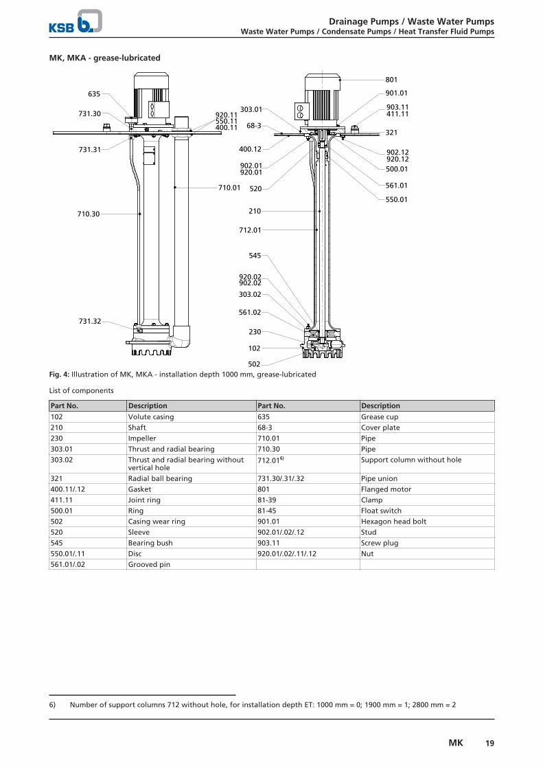
MK, MKA - grease-lubricated
920.11550.11400.11
710.01
210
712.01
545
920.02902.02
303.02
561.02
230
102
502
303.01
68-3
400.12
902.01920.01
520
801
901.01
903.11411.11
321
500.01
561.01
550.01
902.12920.12
635
731.30
731.31
710.30
731.32
Fig. 4: Illustration of MK, MKA - installation depth 1000 mm, grease-lubricated
List of components
Part No. Description Part No. Description
102 Volute casing 635 Grease cup210 Shaft 68-3 Cover plate230 Impeller 710.01 Pipe303.01 Thrust and radial bearing 710.30 Pipe303.02 Thrust and radial bearing without
vertical hole712.016) Support column without hole
321 Radial ball bearing 731.30/.31/.32 Pipe union400.11/.12 Gasket 801 Flanged motor411.11 Joint ring 81-39 Clamp500.01 Ring 81-45 Float switch502 Casing wear ring 901.01 Hexagon head bolt520 Sleeve 902.01/.02/.12 Stud545 Bearing bush 903.11 Screw plug550.01/.11 Disc 920.01/.02/.11/.12 Nut561.01/.02 Grooved pin
6) Number of support columns 712 without hole, for installation depth ET: 1000 mm = 0; 1900 mm = 1; 2800 mm = 2
Drainage Pumps / Waste Water PumpsWaste Water Pumps / Condensate Pumps / Heat Transfer Fluid Pumps
20 MK
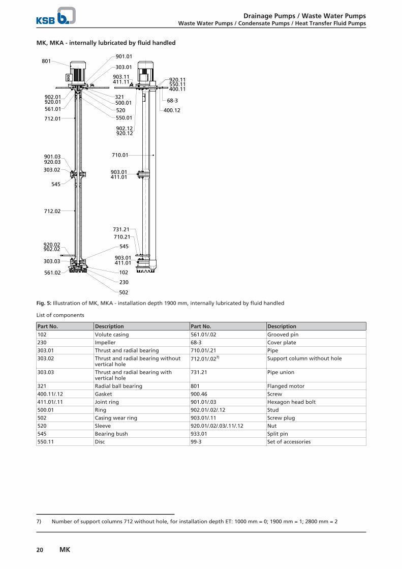
MK, MKA - internally lubricated by fluid handled
920.11550.11400.11
712.01
901.01
712.02
545920.02902.02
303.03
561.02
230
102
502
303.02
68-3
400.12
902.01920.01
545
801
901.03
903.11411.11
321
920.03
500.01561.01
550.01
903.01411.01
520
303.01
710.01
903.01411.01
902.12920.12
710.21731.21
Fig. 5: Illustration of MK, MKA - installation depth 1900 mm, internally lubricated by fluid handled
List of components
Part No. Description Part No. Description
102 Volute casing 561.01/.02 Grooved pin230 Impeller 68-3 Cover plate303.01 Thrust and radial bearing 710.01/.21 Pipe303.02 Thrust and radial bearing without
vertical hole712.01/.027) Support column without hole
303.03 Thrust and radial bearing withvertical hole
731.21 Pipe union
321 Radial ball bearing 801 Flanged motor400.11/.12 Gasket 900.46 Screw411.01/.11 Joint ring 901.01/.03 Hexagon head bolt500.01 Ring 902.01/.02/.12 Stud502 Casing wear ring 903.01/.11 Screw plug520 Sleeve 920.01/.02/.03/.11/.12 Nut545 Bearing bush 933.01 Split pin550.11 Disc 99-3 Set of accessories
7) Number of support columns 712 without hole, for installation depth ET: 1000 mm = 0; 1900 mm = 1; 2800 mm = 2
Drainage Pumps / Waste Water PumpsWaste Water Pumps / Condensate Pumps / Heat Transfer Fluid Pumps
21MK
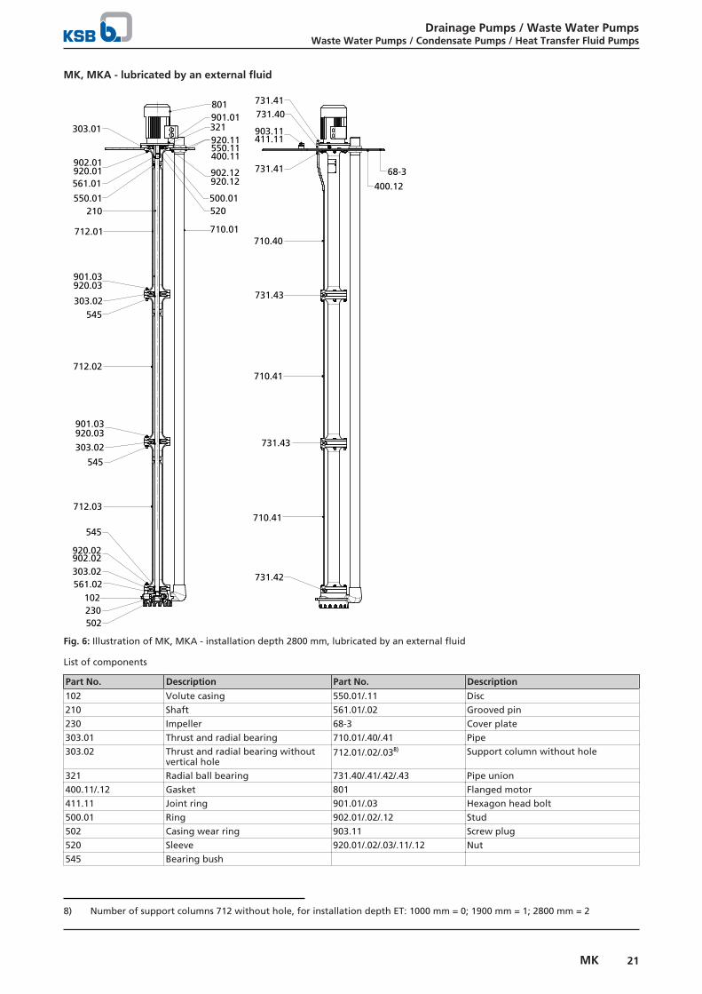
MK, MKA - lubricated by an external fluid
920.11550.11400.11
712.01
901.01
712.03
545
920.02902.02303.02561.02
230102
502
303.02
68-3
400.12
902.01920.01
545
801
901.03
731.42
710.01
321
920.03
500.01
561.01
550.01
902.12920.12
520
303.01
210
710.41
731.43
710.41
731.43
710.40
731.41
903.11411.11
731.40731.41
303.02545
712.02
901.03920.03
Fig. 6: Illustration of MK, MKA - installation depth 2800 mm, lubricated by an external fluid
List of components
Part No. Description Part No. Description
102 Volute casing 550.01/.11 Disc210 Shaft 561.01/.02 Grooved pin230 Impeller 68-3 Cover plate303.01 Thrust and radial bearing 710.01/.40/.41 Pipe303.02 Thrust and radial bearing without
vertical hole712.01/.02/.038) Support column without hole
321 Radial ball bearing 731.40/.41/.42/.43 Pipe union400.11/.12 Gasket 801 Flanged motor411.11 Joint ring 901.01/.03 Hexagon head bolt500.01 Ring 902.01/.02/.12 Stud502 Casing wear ring 903.11 Screw plug520 Sleeve 920.01/.02/.03/.11/.12 Nut545 Bearing bush
8) Number of support columns 712 without hole, for installation depth ET: 1000 mm = 0; 1900 mm = 1; 2800 mm = 2
Drainage Pumps / Waste Water PumpsWaste Water Pumps / Condensate Pumps / Heat Transfer Fluid Pumps
22 MK
MKY
452.62
902.62
920.62
710.01
102
210
230
502
561.02
81-92
902.60920.60
920.61902.61
550.60
457
461.62
801
520
901.01
902.01
902.02
920.01
920.02
561.01321500.01
303.01
452.60550.60
461.60461.61
900.61
81-92341
400.60
712.01/.02/.03
545
303.02/.03
903.01
411.01
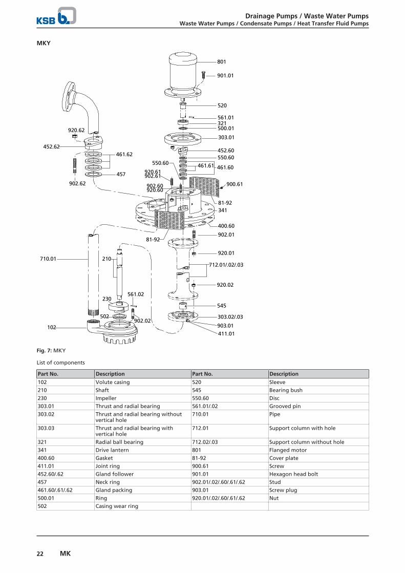
Fig. 7: MKY
List of components
Part No. Description Part No. Description
102 Volute casing 520 Sleeve210 Shaft 545 Bearing bush230 Impeller 550.60 Disc303.01 Thrust and radial bearing 561.01/.02 Grooved pin303.02 Thrust and radial bearing without
vertical hole710.01 Pipe
303.03 Thrust and radial bearing withvertical hole
712.01 Support column with hole
321 Radial ball bearing 712.02/.03 Support column without hole341 Drive lantern 801 Flanged motor400.60 Gasket 81-92 Cover plate411.01 Joint ring 900.61 Screw452.60/.62 Gland follower 901.01 Hexagon head bolt457 Neck ring 902.01/.02/.60/.61/.62 Stud461.60/.61/.62 Gland packing 903.01 Screw plug500.01 Ring 920.01/.02/.60/.61/.62 Nut502 Casing wear ring


KSB SE & Co. KGaAJohann-Klein-Straße 9 • 67227 Frankenthal (Germany)Tel. +49 6233 86-0www.ksb.com
2324
.5/0
7-EN
19/0
6/20
19