Embed Size (px)
Citation preview

Answers for energy.
Type Series 81000TM medium-voltage controllers selection and application guideE50001-F710-A120-X-4A00

Series 81000TM
medium-voltage controllers
Siemens experience gained in over 50 years of supplying medium-voltage motor controllers in the U.S. has been captured in the Series 81000 design.
The objective has been to incorporate features designed to provide safety, while simplifying operation and maintenance, as well as minimizing installation cost.
Series 81000 medium-voltage controllers are designed for use in industrial plants, commercial buildings, electric utility generating plants, cogeneration installations and other electrical systems.
2

Table of contents
Overview 4 - 6
Construction 7 - 17
Motor protection 18 - 20
Vacuum contactors 21 - 25
Fuse applications 26 - 29
Dimensions 30 - 33
Typical layout arrangements 34 - 37
Standard controller components 38 - 43
3
Overview
The Siemens Series 81000TM medium-voltage motor controller has a modular design consisting of one or more contactors, housed in a freestanding sheet steel enclosure. Each controller is NEMA Class E2 and includes three current-limiting fuses. The enclosure is designed for front access, allowing the equipment to be located against a wall or back-to-back.
The design and manufacture of the Series 81000 medium-voltage controller unit is based on our experience as a leading manufacturer of motors worldwide. The benefits of this experience result in control scheme flexibility and increased safety, while simplifying operations, maintenance and minimizing installation costs. Typical applications include:
Squirrel-cage induction motors (non-reversing, reversing or multi-speed)
Reduced-voltage starters (autotransformer, reactor or solid-state type)
Synchronous motors (brush or brushless type)
Transformer feeders
Capacitor bank feeders
Power bus feeders (tie).
The utilization voltage range for controllers is 2.3 kV through 13.8 kV.
The Siemens Series 81000 medium-voltage controller allows the user to combine vacuum contactors, latched contactors and load-break switches in one lineup. The user can also connect directly to Siemens type GM-SG medium-voltage metal-clad switchgear with a transistion section. This provides extreme flexibility in systems design.
Load-break switches (LBS)
Drawout controllers
Drawout controllers include:
Full-voltage non-reversing (FVNR)
Reduced-voltage primary reactor (RVPR)
Reduced-voltage autotransformer (RVAT)
Reduced-voltage solid-state (SSRV)
Brushless synchronous (BL-SYNCH)
Brushtype synchronous (BT-SYNCH)
Two-speed two-winding (2S2W)
Two-speed one-winding (2S1W)
Reversing.
4

Overview
Table 1: Controllers and load-break switches (LBS)
Controller type
2.3 kV 4.16 kV 6.9 kV 13.8 kV
Maximum motor size
Drawout to 3,000 HP to 5,500 HP to 7,000 HP to 5,500 HP
SSRV to 3,000 HP to 5,500 HP to 4,000 HP to 6,500 HP
Load-break switch (LBS)
600 A Fused Fused ---- ----
Unfused Unfused Unfused ----
1,200 A Fused Fused ---- ----
Unfused Unfused Unfused ----
Table 2: Ratings
System voltage
Vacuum contactor
Enclosed continuous ampere rating
Interrupting capacity
Motor horsepower rating (three-phase)
Transformer loads
Unfused class E1
Fused class E2
Synchronous motors
Induction motors
Maximum motor fuse rating
Maximum three-phase
Maximum fuse rating
kV Type A kA kA 0.8 PF
1.0 PF
HP kVA
2.3 97H3 360 5 50 1,500 1,750 1,500 24R 1,500 450E
2.3 96H6 720 7.2 50 3,000 3,500 3,000 57X 2,000 600E
4.0 97H3 360 5 50 2,500 3,000 2,500 24R 2,500 450E
4.0 96H6 720 7.2 50 5,500 6,000 5,500 57X 3,500 600E
4.6 97H3 360 5 50 2,500 3,000 2,500 24R 2,500 450E
4.6 96H6 720 7.2 50 5,500 6,000 5,500 57X 4,000 600E
6.91 97H3 360 4.2 50 4,000 5,000 4,000 24R 1,500 200E
6.91 96H6 720 7.2 50 7,000 7,500 7,000 57X 2 2
13.8 3TL71 300 3.0 50 5,500 6,000 5,500 300E 5,500 300E
Footnotes:1. Nominal motor voltage 6.6 kV. (Temporary overvoltage of 7.6 kV)2. Consult factory.
5

Overview
Contactors class E1 unfused
NEMA refers to this unfused, magnetically held device as a class E1 controller. Type 97H3 (360 A) vacuum contactors are rated 5 kA (up to 5.0 kV) and 4.2 kA (up to 7.2 kV) interrupting capacity, while the type 96H6 (720 A) vacuum contactor is rated 7.2 kA interrupting capacity up to 7.2 kV. Type 3TL71 (300 A) vacuum contactor is rated 3.0 kA interrupting capacity up to 13.8 kV.
Contactors class E2 fused
To meet interrupting capability required for NEMA class E2 controllers, types 97H3, 96H6 and 3TL71 contactors are provided with primary current-limiting fuses in all three phases. The resulting interrupting ratings are shown in Table 2.
Standards
The key standards applicable to medium-voltage controllers are:
NEMA ICS 3-2005, part 1
UL-347
NEC (Article 490).
Series 81000 controllers with vacuum contactors comply fully with these standards, and can be provided in compliance with specialty standards, such as the California Code.
Vacuum technology
Series 81000 controllers utilizing type 97H3, 96H6 or 3TL71 vacuum contactors offer extended service life and provide long mechanical and electrical life with minimal maintenance.
Arc interruption is completely contained within vacuum interrupters, eliminating the need for arc chutes, blowout coils, pole plates and similar wear items.
Extended electrical life
Since arc interruption takes place in a sealed environment within the vacuum interrupter, arcing times are very short. As a result, arc erosion of the contacts is minimal, and an operating life of 250,000 operations at rated load-current is typical.
Single-phase protection
The Siemens type 3RU overload relay (standard) is available in the Series 81000. Unlike conventional overload relays provided by other manufacturers, the type 3RU includes standard single-phase protection.
UL Listing
The Series 81000 offers a broad range of UL Listed (and C-UL) class E2 controllers. Consult your local Siemens representative for information on UL Listing (or C-UL) status for specific projects.
Power fuses
The current limiting fuses used with type 97H3 vacuum contactors are ANSI Class "R" type FM (up to 4.8 kV) and type A720R (over 4.8 kV and up to 7.2 kV) rated for motor starting duty.
Class "E" fuses, used for non-motor loads such as transformers and capacitor banks, can also be provided in Series 81000 controllers.
Class "E" fuses, type CL-14 are used for full- voltage and solid-state, reduced-voltage starters above 7.2 kV up to 13.8 kV.
6

Enclosures
Available in a variety of styles to meet most applications, enclosure types include:
NEMA 1 non-gasketed
NEMA 1A gasketed
NEMA 2 drip-proof
NEMA 12 dust-tight
NEMA 3R non-walk-in
NEMA 3R walk-in
External finish is ANSI 61 light gray polyester, electrostatically applied. Special colors and finishes are optionally available.
Compartment segregation
Each Series 81000 controller assembly consists of three areas completely segregated from one another:
Contactor compartment
Power bus system (high-voltage)
Low-voltage section.
A standard vertical structure consists of three 30" (762 mm) high compartments. One, two or three controllers (depending on rating) may be included in one structure.
When three controllers are required, the horizontal bus (including ground bus) is mounted in an additional top-mounted 10" (254 mm) (13" (330 mm) for 3,000 A) high bus compartment. An optional configuration using two 45" (1,143 mm) high compartments with top-mounted bus is also available to comply with American Petroleum Institute specifications.
A 15kV FVNR structure consists of three vertical structures. The overall controller dimensions are 72" (1,828 mm) wide, 48" (1,219 mm) deep and 90" (2,186 mm) high, without main bus. The incoming cable section is located on the right, while the outgoing cable section is located on the left. Both cable sections are 18“ (457 mm) wide. The center section includes the drawout fuse-carriage, stationary main contactor, low-voltage compartment and a 1.0 kVA fixed-mounted CPT.
Construction
Figure 1: Series 81000 drawout controller compartment segregation. Unit is not complete and is shown for illustrative purposes only.
Grounded steel barriers between power bus and vacuum contactors
Low-voltage or controller compartment
Shutters
Steel barrier between compartments
A 15 kV SSRVS structure consists of three vertical sections. The overall controller dimensions are 96" (2,438 mm) wide, 66" (1,677 mm) deep and 90" (2,186 mm)high, without main bus. The SCR chassis units are located in the two sections on the left end, which also includes the low- voltage compartment, a 1.0 kVA fixed-mounted control power transformer and the termination space for the outgoing load-side cables. The third section houses the drawout fuse-carriage, as well as the stationary main and bypass contactors and the termination space for the incoming power cables.
Main bus can be provided on 15 kV FVNR and 15 kV SSRVS controllers, using a top-mounted main bus housing. This adds 15" (381 mm) to the height of the structure. The main bus is available in 1,200 A, 2,000 A or 3,000 A ratings.
7

Construction
Figure 2: Low-voltage door-in-door compartment for panel devices
Figure 3: Main and vertical bus construction (shown with optional insulation). Transitions to type GM-SG 5 kV-15 kV switchgear are available.
Construction
Power bus
Power bus is isolated behind grounded steel barriers. Automatic shutters are provided on drawout controllers to cover the line-side bus stabs whenever a starter door is opened or the drawout carriage is in the disconnect position. Horizontal bus ratings range from 1,000 A through 3,000 A and are detailed in Table 3. Vertical tap buses in each section are rated 360 A, 540 A or 720 A, depending on the application. The standard bus material is silver-plated copper bus. Tin-plating is available as an option. Insulated bus with boots are available as options.
Low-voltage compartment (up to 7.2kV)
All active starter compartment front panels are provided with a "door-in-door" for access to the controller low-voltage area. Devices normally mounted in this section include the Siemens 9350 power meter, overload relay, ammeter, control relays, timing relays, pushbuttons, indicating lights, etc. Location within this section isolates the devices from any source of high voltage and allows access to these control compartments without interrupting service. Terminal blocks for control circuit wiring terminations are also accessible in this compartment. When extensive metering or special protective devices are required, the upper 30" (762 mm) high compartment can be used as a separate low-voltage compartment in addition to the "door-in-door" low-voltage compartment associated with each individual controller.
8

Bus type
Continuous amperes (A)
Conductor size in inches (mm)
Conductor material
Current density (A/in2)
Main horizontal 1,000 0.25 (6) x 3.0 (76) Copper 1,333
1,200 0.375 (10) x 3.0 (76) Copper 1,067
2,000 Two 0.375 (10) x 3.0 (76) Copper 889
3,0001 Three 0.50 (13) x 3.0 (76) Copper 667
Vertical 300 (15 kV) 0.25 (6) x 2.0 (51) Copper 600
360 0.25 (6) x 1.0 (25) Copper 1,440
540 0.25 (6) x 1.5 (38) Copper 1,440
720 0.50 (13) x 2.0 (51) Copper 720
Ground 600 0.25 (6) x 2.0 (51) Copper 1,200
Interlocking
A combination of mechanical and electrical interlocks are included to:
Prevent inward and back movement of the drawout carriage (isolation switch), unless the contactor is open
Prevent the opening of the high-voltage compartment door, unless the drawout carriage (isolation switch) is in the disconnect position
Prevent the forward movement of the drawout carriage (isolation switch) to the connected position, unless the high-voltage compartment door is closed.
Construction
Table 3: Bus ratings
Footnote:1. 3,000 A bus must be located on
top of unit in 13” (330 mm) top hat (15” (381 mm) for 15 kV).
Drawout controllers isolation disconnect (drawout mechanism)
Series 81000 controllers use the complete contactor (or fuse carriage drawout assembly for 720 A or 15 kV controllers) as the high-voltage isolation switch, as described in NEMA ICS 3-2005, Part 1, clause 7.2.c and UL-347-2009, clause 5.202.2. Horizontal forward and back movement of the drawout assembly simultaneously opens and closes the line and load disconnect contacts.
Because both line-side and load-side terminals are disconnected, there is no need for grounding the load-side terminals in the open position. Non-conducting glass-polyester barriers (shutters) completely isolate the stationary-line terminals. The shutter mechanism is positively driven by the same linkage mechanism that moves the drawout carriage from the connected to the disconnected position.
The drawout operation is a simple one-step process. After the contactor is open (or de-energized), move the racking handle to the "OFF" position (disconnected), open the starter door and the contactor is ready to be rolled out of the compartment.
9
CPT kVA
Primary fuse rating
Secondary fuse rating
2.3 kV 3.3 kV 4.0 kV 4.6 kV 6.6 kV 115 V 230 V
0.75 1E 1E 1E 0.5E 1E 10A 6.25A
2.0 3E 2E 2E 2E 1E 20A 10A
3.0 4E 3E 2E 2E 2E 30A 15A
Construction
Test circuit
Each Series 81000 controller is provided with a built-in test circuit for operation of the contactor from a remote source of control power, when the "test-run" switch is set at the "test" position. This circuit will function only if the contactor is disconnected from its primary source of power and the "test-run" switch is set at the "test" position. It allows maintenance and operation of the main contactor and low-voltage control circuitry without requiring energizing the motor, or disconnecting any load cables, and prevents back-energization of the CPT.
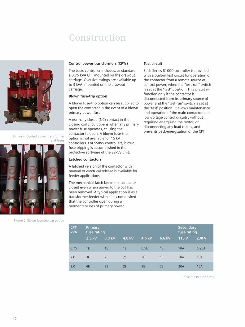
Figure 4: Control power transformer and fuses
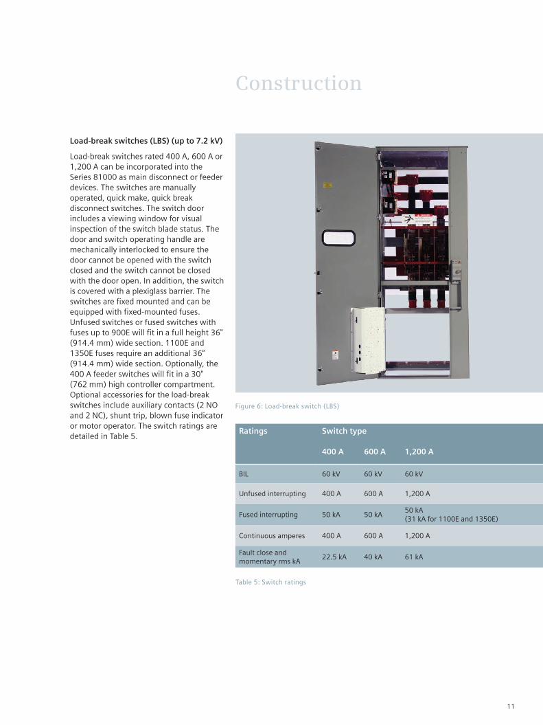
Figure 5: Blown fuse-trip bar option
Table 4: CPT fuse sizes
Control power transformers (CPTs)
The basic controller includes, as standard, a 0.75 kVA CPT mounted on the drawout carriage. Oversize ratings are available up to 3 kVA, mounted on the drawout carriage.
Blown fuse-trip option
A blown fuse-trip option can be supplied to open the contactor in the event of a blown primary power fuse.
A normally closed (NC) contact in the closing coil circuit opens when any primary power fuse operates, causing the contactor to open. A blown fuse-trip option is not available for 15 kV controllers. For SSRVS controllers, blown fuse tripping is accomplished in the protective software of the SSRVS unit.
Latched contactors
A latched version of the contactor with manual or electrical release is available for feeder applications.
The mechanical latch keeps the contactor closed even when power to the coil has been removed. A typical application is as a transformer feeder where it is not desired that the controller open during a momentary loss of primary power.
10
Construction
Load-break switches (LBS) (up to 7.2 kV)
Load-break switches rated 400 A, 600 A or 1,200 A can be incorporated into the Series 81000 as main disconnect or feeder devices. The switches are manually operated, quick make, quick break disconnect switches. The switch door includes a viewing window for visual inspection of the switch blade status. The door and switch operating handle are mechanically interlocked to ensure the door cannot be opened with the switch closed and the switch cannot be closed with the door open. In addition, the switch is covered with a plexiglass barrier. The switches are fixed mounted and can be equipped with fixed-mounted fuses.Unfused switches or fused switches with fuses up to 900E will fit in a full height 36" (914.4 mm) wide section. 1100E and 1350E fuses require an additional 36” (914.4 mm) wide section. Optionally, the 400 A feeder switches will fit in a 30" (762 mm) high controller compartment. Optional accessories for the load-break switches include auxiliary contacts (2 NO and 2 NC), shunt trip, blown fuse indicator or motor operator. The switch ratings are detailed in Table 5.
Figure 6: Load-break switch (LBS)
Table 5: Switch ratings
Ratings Switch type
400 A 600 A 1,200 A
BIL 60 kV 60 kV 60 kV
Unfused interrupting 400 A 600 A 1,200 A
Fused interrupting 50 kA 50 kA50 kA (31 kA for 1100E and 1350E)
Continuous amperes 400 A 600 A 1,200 A
Fault close and momentary rms kA
22.5 kA 40 kA 61 kA
11

Construction
Table 6: Starting characteristics of controller type expressed in percent rated value
Starter type
Motor voltage
Motor current
Line current
Torque
FVNR 100 100 100 100
RVAT 80% tap 80 80 64 64
RVAT 65% tap 65 65 42 42
RVAT 50% tap 50 50 25 25
RVPR 80% tap 80 80 80 64
RVPR 65% tap 65 65 65 42
RVPR 50% tap 50 50 50 25
Figure 7: RVAT - main vacuum contactor compartment
Figure 8: RVAT - autotransformer and start contactor compartment
Reduced-voltage starters
For loads requiring reduced-voltage starting, the Series 81000 design offers three options. Primary reactor (RVPR), autotransformer (RVAT) and solid-state (SSRV) controllers are available as drawout controllers.
Reduced-voltage primary reactor (RVPR) controllers
Reduced-voltage primary reactor controllers consists of a main contactor, run contactor and a primary reactor with 80, 65 and 50 percent voltage taps, factory set at 65 percent. The standard reactors are NEMA medium duty-rated for three 30-second starts per hour, heavy-duty starting reactors are available for special applications. The primary reactors are sized based on the motor locked rotor current.
Reduced-voltage autotransformer (RVAT) controllers
Reduced-voltage autotransformer controllers consist of a main contactor, shorting contactor, run contactor and an autotransformer with 80, 65 and 50 percent voltage taps, factory set at 65 percent. The standard autotransformers are NEMA medium duty-rated for three 30-second starts per hour. Heavy-duty autotransformers are available for special applications. The autotransformers are sized based on the locked rotor current of the motor. Starting sequence is closed transition.
12

Construction
Solid-state, reduced-voltage (SSRV) controllers
Solid-state, reduced-voltage controllers consist of a main contactor, SCR chassis and a line-start rated bypass contactor. The SSRV starter provides the most flexible starting options, offering selectable current or voltage ramps. For emergency full-voltage starting, the bypass contactor can be used as an across-the-line starter by changing a control switch position. As an option, the starter can be equipped with a permanent emergency across-the-line starting option including an additional set of current transformers, normal/emergency selector switch and a bi-metal overload relay. Repositioning power cables for this option is not required.
Benefits of solid-state, reduced-voltage starting:
Reduce torque shock damage
Increase motor and drive train reliability
Limit starting kVA
Maintain future system flexibility
Soft start and soft stop pumps to control water hammer
Reduce hydraulic/mechanical problems.
The SCR logic control incorporates the following standard protection, metering and parameter adjustments:
Initial voltage - 10 to 50 percent nominal voltage (5 to 85 percent optional)
Current limit -100 to 400 percent of motor full-load amperes (FLA) (100 to 700 percent optional)
Acceleration time -1 to 30 seconds (1 to 90 seconds optional)
Deceleration time - 0 to 30 seconds (0 to 90 seconds optional)
Pump control - four closed-loop start and stop curves
Pulse (kick) start
<1 second 70 to 700 percent of motor FLA
≥1 second 70 to 400 percent of motor FLA
Under voltage trip - 50 to 90 percent, adjustable trip delay 1 to 10 seconds
Over voltage trip - 110 to 125 percent, adjustable trip delay 1 to 60 seconds
Under current (load loss) trip - 20 to 90 percent of motor FLA (1%), adjustable trip delay 1 to 40 seconds
Allowable restarts - 0 to 10, adjustable time inhibit
Electronic overload class - 5 to 30 ANSI or IEC
Electronic shear pin - trips within one cycle of setpoint
Phase loss - one or more phases missing
Phase sequence - phase sequence incorrect
Shorted solid-state silicon-controlled rectification (SCR) internal fault detected
Connection error - internal fault/motor connection
Starter over temp - heatsink over temperature
Elapsed time meter
Maximum current
Starting time for last start
Total number of starts
Cause of last fault
Percentage of current at last trip
Total number of trips
RS-485 with Modbus remote terminal unit (RTU) protocol
Opto-isolated inputs
Non-volatile memory for programming and faults
Programmable in four languages.
Figure 9: Solid-state, reduced-voltage controller
13

Construction
Current transformers (CTs)
Starters using conventional overload relays are provided with current transformers mounted in the cable termination area of the controller compartment. These are used to drive the overload relay, ammeter or other devices that require a current input.
CT selection takes into consideration the burden and accuracy requirements that are appropriate for the specified instru-mentation and protective devices. The secondary current rating is always 5 A. The primary current rating is selected so that the actual secondary current will be between 3 A and 4 A with the motor (or other load) operating at full load.
Applications at 7.2 kV or below use the type 81CT10 CT with standard accuracy rating. Higher accuracy class CT (type 81CT20) or higher burden CTs (type 81CT50) are also available as options.
Applications above 7.2 kV use type MD CTs.
Refer to Tables 7-10 for details.
Figure 10: Type 3RB overload relay
Figure 11: Type 3RU overload relay
Figure 12: Current transformers and cable termination area
Overload protection - types 3RU or 3RB
Running overcurrent (overload) protection for the motor must also be provided according to NEMA standards. This overload (or longtime) protection can be provided by the Siemens type 3RU (OLR) bimetallic thermal overload relay. This three-phase adjustable relay provides inherent single-phase protection and phase unbalance protection with NEMA class 10 tripping characteristics, providing optimum protection for motors having acceleration times of six seconds or less and allowable hot locked rotor times of five seconds or more. It is equipped with an isolated normally open contact to actuate a remote alarm in the event of an overload trip.
For applications that require longer acceleration times, Siemens offers the type 3RB solid-state overload relay, with class 10, 20 or 30 tripping characteristics.
For unusual applications, solid-state or switchgear type overcurrent relays are available.
14

Ratio 60 Hz metering accuracy at burden Relay class
Primary cable turns
Cable size AWG
Used on
B0.1 B0.2 B0.5 B0.9
30:5 0.6 0.6 1.2 2.4 C08 Five #8 360 A
40:5 0.3 0.6 0.6 1.2 C10 Five #8 360 A
50:5 0.3 0.6 0.6 1.2 C10 Four #6 360 A
75:5 0.3 0.3 0.3 0.6 C10 Four #6 360 A
100:5 0.3 0.6 0.6 1.2 C10 Two #2 360 A
150:5 0.3 0.3 0.3 0.6 C10 Two #2 360 A
200:5 0.3 0.6 0.6 1.2 C10 One 2/0 360 A
250:5 0.3 0.3 0.6 1.2 C10 One 2/0 360 A
300:5 0.3 0.3 0.3 0.6 C10 One 2/0 360 A
400:5 0.3 0.3 0.3 0.3 C10 One 4/0 360 A
500:5 0.3 0.3 0.3 0.3 C20 One 4/0 360 A
600:5 0.3 0.3 0.3 0.3 C20 One 4/0 360 A
500:5 0.3 0.3 0.3 0.3 C20 One 4/0 720 A
600:5 0.3 0.3 0.3 0.3 C20 One 4/0 720 A
750:5 0.3 0.3 0.3 0.6 C20 One 4/0 720 A
800:5 0.3 0.3 0.3 0.3 C20 One 4/0 720 A
1,000:5 0.3 0.3 0.3 0.3 C10 One 4/0 720 A
Table 7: Relay class C10 standard CTs, Siemens type 81CT10
Construction
Ratio 60 Hz metering accuracy at burden Relay class
Primary cable turns
Cable size AWG
Used on
B0.1 B0.2 B0.5 B0.9
25:5 0.6 0.6 1.2 2.4 C20 Four #6 360 A
30:5 0.6 0.6 1.2 2.4 C20 Five #6 360 A
40:5 0.6 0.6 0.6 1.2 C20 Five #6 360 A
50:5 0.6 0.6 1.2 2.4 C20 Two #6 360 A
75:5 0.6 0.6 1.2 2.4 C20 Two #6 360 A
100:5 0.6 0.6 1.2 2.4 C20 One #2 360 A
150:5 0.6 0.6 1.2 2.4 C20 One #2 360 A
200:5 0.6 0.6 0.6 1.2 C20 One 2/0 360 A
250:5 0.3 0.3 0.6 1.2 C20 One 2/0 360 A
300:5 0.3 0.3 0.3 0.6 C20 One 2/0 360 A
400:5 0.3 0.3 0.3 0.6 C20 One 4/0 360 A
600:5 0.3 0.3 0.3 0.3 C20 One 4/0 360 A
600:5 0.3 0.3 0.3 0.3 C20 One 4/0 720 A
750:5 0.3 0.3 0.3 0.3 C20 One 4/0 720 A
800:5 0.3 0.3 0.3 0.3 C50 One 4/0 720 A
1,000:5 0.3 0.3 0.3 0.3 C50 One 4/0 720 A
Table 8: Relay class C20 optional CTs, Siemens type 81CT20
15

Construction
Ratio 60 Hz metering accuracy at burden Relay class
Primary cable turns
Cable size AWG
Used on
B0.1 B0.2 B0.5 B0.9
25:5 0.3 0.6 1.2 1.2 C50 Six #6 360 A
30:5 0.6 0.6 1.2 2.4 C50 Five #6 360 A
40:5 0.3 0.3 0.6 0.6 C50 Five #6 360 A
50:5 0.3 0.6 1.2 1.2 C50 Three #6 360 A
75:5 0.3 0.6 1.2 1.2 C50 Two #6 360 A
100:5 0.3 0.3 0.6 0.6 C50 Two #2 360 A
150:5 0.3 0.6 1.2 1.2 C50 One #2 360 A
200:5 0.3 0.3 0.6 0.6 C50 One 2/0 360 A
250:5 0.3 0.3 0.6 1.2 C50 One 2/0 360 A
300:5 0.3 0.3 0.6 0.6 C50 One 2/0 360 A
400:5 0.3 0.3 0.3 0.3 C50 One 4/0 360 A
600:5 0.3 0.3 0.3 0.3 C50 One 4/0 360 A
600:5 0.3 0.3 0.3 0.3 C50 One 4/0 720 A
750:5 0.3 0.3 0.3 0.3 C50 One 4/0 720 A
800:5 0.3 0.3 0.3 0.3 C50 One 4/0 720 A
1,000:5 0.3 0.3 0.3 0.3 C50 One 4/0 720 A
Table 9: High-burden optional CTs, Siemens type 81CT50
Ratio 60 Hz metering accuracy at burden Relay classB0.1 B0.2 B0.5 B0.9
100:5 2.4 ---- ---- ---- C15
150:5 0.6 2.4 ---- ---- C20
200:5 0.6 1.2 ---- ---- C25
250:5 0.6 1.2 2.4 ---- C35
300:5 0.6 0.6 1.2 2.4 C40
400:5 0.3 0.6 1.2 2.4 C60
500:5 0.3 0.3 0.6 1.2 C75
Table 10: Type MD torrodial standard-accuracy CTs for 15 kV controllers
16

Construction
Voltage transformers (VTs)
Optional voltage transformers are available in fixed-mounted or trunion-mounted (roll-out for 7.2 kV and above) versions. Trunion-mounted VTs typically require a 30" (762 mm) high drawout compartment, while fixed-mounted VTs can be mounted in the upper low-voltage compartment and are barriered to prevent accidental contact (refer to Table 11 for VT ratings).
Distribution transformers
For larger auxiliary loads that need to be fed from the Series 81000 medium-voltage control center, NEMA standard distribution transformers can be installed. These are available in single-phase sizes from 3 kVA to 25 kVA and in three-phase sizes from 9 kVA to 45 kVA. Transformers include standard primary taps (four 2.5 percent taps) and class H insulation rated 180 °C temperature class. The distribution transformers are provided with primary fuse protection and a molded-case circuit breaker on the secondary side. The transformers are stationary mounted and are rated 30 kV BIL. As standard, the primary fuses are fixed mounted. Optional trunion-mounted fuses are also available. The fuse trunion is mechanically interlocked with the secondary molded case circuit breaker to ensure that secondary loads are de-energized prior to operation of the trunion.
Transformers will require a 30" (762 mm) high controller compartment, an additional 30" (762 mm) height is required for the optional fuse trunion.
Auxiliary contacts
All vacuum contactors are supplied with two NO and two NC auxiliary contacts available for customer use. Extra contacts are available through the use of the master relay (MR) or extra control relays.
Figure 13: Voltage transformer (trunion-mounted shown)
Voltage class
Ratio Accuracy class at 120 V secondary
VA thermal rating1
BIL rating
W, X Y X
5 kV 2,400:120 0.3 0.6 1.2 600 45 kV
5 kV 4,200:120 0.3 0.6 1.2 600 45 kV
5 kV 4,800:120 0.3 0.6 1.2 600 45 kV
7 kV 6,900:120 0.3 0.3 1.2 1,500 75 kV
7 kV 7,200:120 0.3 0.3 1.2 1,500 75 kV
15 kV 12,000:120 0.3 0.3 1.2 1,500 95 kV
15 kV 14,400:120 0.3 0.3 1.2 1,500 95 kV
Table 11: Voltage transformer ratings ‒ fixed- or trunion-mounted
Footnote:1. 30 °C ambient.
17

Motor protection
Motor protection options
Drive motors often play a decisive role in the success of a production process. Motor breakdowns frequently result in damage to driven equipment and production shutdowns. The resulting cost significantly exceeds the cost of repairing the motor. Optimum design of the motor protection ensures that damage from thermal overload is minimized with little reduction in service life. Secondary faults are minimized in the event of short circuits, ground faults and winding faults. The spectrum extends from small medium-voltage motors with an output of a few hundred horsepower to large medium-voltage motors with outputs measured in thousands of horsepower. Protection system design must be based on the rating of the motor, the importance of the drive for the technological process, the operating conditions and the requirements of the motor manufacturer.
Commonly specified motor protection functions and motor protective relay selection tables are provided in Table 12.
Figure 14: Type 7SK80 protective relay
Fault Protection ANSI number
Stator thermal overload Stator thermal overload protection 49
Rotor thermal overload during start
Excessive starting time or blocked rotor
Too frequent
Motor starting time supervision
Restart inhibit
48
66, 49R
Ground fault Ground fault protection 50G, 64G, 67G
Short circuit Overcurrent time protection
Current differential protection
50, 51
87
Phase loss Negative sequence protection 46
Bearing overload Temperature sensors (RTDs) 38
Overheating of plan on unloaded drives (pumps, compressors) Undercurrent protection 37
Undervoltage Undervoltage protection 27
Induction operation (of a synchronous machine) Underexcitation (loss of field) protection 40
Table 12: Protection functions for various types of motor faults
18

Motor protection
Induction machine Synchronous machine
up to 1,000 HP up to 2,000 HP
Type 7SK80 or 7SJ61
Basic motor protection plus 14, 27, 50BF, 51M and 86
Control functions
Additional input/outout (I/O)
Flexible protection functions
Larger human machine interface (HMI) display
Up to 12 external resistance temperature detectors (RTDs)1
Type 7UM61
Basic motor protection plus 27/59, 32, 51V, 60, 67 and 81U/O
Control functions
Additional I/O
Larger HMI display
Up to 12 external RTDs1
1,000 HP - 2,500 HP Over 2,000 HP
Type 7SK80 or 7SJ61
Basic motor protection plus 14, 27, 50BF, 51M and 86
Control functions
Additional I/O
Flexible protection functions
Larger HMI display
Up to 12 external RTDs1
Type 7UM61
Basic motor protection plus 32, 27/59, 51V, 60, 67 and 81U/O for variable speed applications
Control functions
Additional I/O
Larger HMI display
Up to 12 external RTDs1
Type 7UM62
Basic motor protection plus 24, 27/59, 32, 40, 50BF, 51V, 67, 81R, 81U/O and 87
Control functions
Additional I/O, transducer outputs
Larger HMI display
Up to 12 external RTDs1
Over 2,500 HP
Type 7UM61
Basic motor protection plus 32, 27/59, 51V, 60, 67 and 81U/O
Control functions
Additional I/O
Larger HMI display
Up to 12 external RTDs1
Table 13: Motor protection selection
Footnote:1. Optional with up to five RTD inputs in protective relay (type 7SK80 only) or up to 12 RTDs using two type 7XV5662 RTD units.
19

Motor protection
Function Description Type
7SJ60 7SK80 7SJ61 7SJ62 7UM61 7UM62
50/51 Overcurrent instaneous/time Yes Yes Yes Yes Yes Yes
50N/51N Ground overcurrent instaneous/time Yes Yes Yes Yes Yes Yes
51M Load jam ---- Yes Optional Yes ---- ----
51V Voltage controlled time ---- ---- ---- ---- Yes Yes
37 Undercurrent ---- Yes Yes Yes ---- Yes
87 Differential ---- ---- ---- ---- ---- Yes
87N Ground differential ---- ---- Yes Yes ---- ----
50BF Breaker failure ---- Yes Yes Yes Yes Yes
46 Phase balance (negative sequence) current Yes Yes Yes Yes Optional Optional
67 Directional overcurrent ---- ---- ---- Yes Yes Yes
67N Directional ground overcurrent ---- Optional ---- Yes Yes Yes
32 Directional (reverse) power ---- Optional ---- ---- Yes Yes
27/59 Under/over voltage ---- Optional ---- Yes Yes Yes
47 Phase rotation ---- Optional ---- Yes Yes Yes
81U/O Over/under frequency ---- Optional ---- Yes Yes Yes
59N Ground overvoltage ---- Optional ---- Yes Yes Yes
40 Under excitation (loss of field) ---- ---- ---- ---- Optional Yes
24 Over excitation (volts per hertz) ---- ---- ---- ---- Yes Yes
48/14 Incomplete sequence/underspeed Yes Yes Optional Yes Optional Optional
66 Restart inhibit ---- Yes Optional Yes Optional Yes
86 Lockout ---- Yes Yes Yes Yes Yes
38 RTD monitoring ---- Optional1 Optional1 Optional1 ---- Optional1
---- I/O binary inputs/binary outputs 3/1 3/5 3/4 8/8 7/12 7/15
Table 14: Protection functions for various types of motor faults
Footnote:1. Optional with up to five RTD inputs in protective relay (type 7SK80 only) or up to 12 RTDs using two type 7XV5662 RTD units.
20

The type 97H3 drawout vacuum contactor consists of:
A low-voltage section containing the main coil drive and auxiliary contacts
A medium-voltage section housing the vacuum interrupters
A support structure providing mounting for the power fuses, control transformer and primary fuses and drawout finger assemblies.
Since arc interruption is accomplished completely within the vacuum interrupters, arc chutes, blowout coils and pole plates are not required. Stationary and movable power contacts are located inside the vacuum interrupters. A stainless steel bellows attached to the movable contact ensures a complete seal and vacuum integrity. Because the contacts are sealed in the vacuum interrupter and have only a short stoke, long mechanical and electrical life is achieved.
Siemens type 97H3 series vacuum contactor is mechanically interchangeable with the previous type 94H3 series. The type 96H3 series is mechanically interchangeable with the previous type 93H3 series contactors.
Type 97H3 360 A drawout vacuum contactor
This vacuum contactor forms the centerpiece for the medium-voltage controller. It is a drawout assembly that racks onto or off of the primary stabs in the stationary housing. The supporting base consists of a bolted steel frame. The pushrods, contact support blocks and other insulating parts are constructed of glass polyester. All insulating material that is in contact with high-voltage current carrying parts is flame retardant and track resistant.
The distinctive features of the Siemens type 97H3 vacuum contactor is high reliability, long service life, compact dimensions and the ability to deal with most motor switching duties. They are suitable for loads of many types, including motors, transformers, capacitors and resistive loads.
In addition to the advantages of long mechanical and electrical life with low maintenance, the contacts are resistant to adverse atmospheric environments and are light in weight.
The vacuum contactor with single- or double-barrel power fuses can be installed in Series 81000 class E2 controllers of either one-, two- or three-high construction.
Vacuum contactors
Figure 15: Type 97H3 360 A fused vacuum controller - front view
Figure 16: Type 97H3 360 A fused vacuum controller - rear view
21

Vacuum contactors
Type 96H6 720 A vacuum contactor
The type 96H6 720 A vacuum contactor employs a similar philosophy to the drawout type 97H3 360 A contactors, except that only the primary current- limiting fuses are mounted on the drawout carriage. The vacuum contactor is stationary mounted, connected to the load stabs of the drawout cell with cables rated for 720 A. The use of the drawout fuse carriage preserves all of the advantages of drawout construction.
Figure 17: Type 96H6 720 A fuse carriage - front view
Figure 18: Type 96H6 720 A fuse carriage - rear view
Figure 19: Typical control schematic for FVNR squirrel-cage controller
LSI
CXFU
Run Test
C BA
6
Stop 1 2Start
RSI TFU
115 V or 230 V CPT
X1X2
115 V or 230 V test power
Push to test
DC drive unit
C
12
L1
RLL2C
MROL
8 9
3
MR 10 A 14 M 13 B11
MR 15 F A1 A2 D 13
M CC
M CC
1 1 2 2
Additional auxiliary contacts
M M M M84 83 43 44 21 22 32 31
G H I J K L M N
12 13 14 15 16 17 18 19
Legend:CPT = Control power transformer CXFU = Fuse for CPT secondary LSI = Line switch interlock M = Main vacuum contactor MR = Master relay M CC = Main vacuum contactor magnet coil RL = High-voltage light RSI = Racking switch interlock TFU = Fuse for test power
Test switch contact development
Run Test
A X
B X
C X
X = Contacts closed
22

Vacuum contactors
Item Magnetically held Latched
Rated voltage 7,200 V 7,200 V
Rated current 360 A 360 A
Permissible switching frequency 1,200/hour 60/hour
Mechanical life (number of operations) 1,000,000100,000 (latch mechanism); 1,000,000 contactor
Electrical life (number of operations) 250,000100,000 (latch mechanism); 250,000 contactor
Closing time 150 ms 150 ms
Minimum closing command duration 300 ms 300 ms
Opening time2 325 +/- 75 ms3 > 45 ms
Arcing time 10 to 20 ms 10 to 20 ms
Pick-up voltage AC or DC, nominal 85% rated (hot); 70% rated (cold) 85% rated (hot); 70% rated (cold)
Drop-out voltage AC or DC, nominal 74 +/- 2 V ----
Minimum trip voltage ---- 85% rated voltage
Rated control voltage 115 to 240 V (50/60 Hz); 125 to 250 Vdc 115 to 240 V (50/60 Hz); 125 to 250 Vdc
Coil circuit inrush 600 W 600 W
Coil circuit holding 90 W ----
Tripping (latched opening release) ---- 500 W
Auxiliary contact arrangement 2 NO + 2 NC 2 NO + 2 NC
Auxiliary contact rating
Continuous current
AC making/breaking
DC making/breaking
10 A, 600 V (NEMA class A600)
10 A
7,200 VA not over 60 A/
720 VA not over 6 A
10 A@24 V; 5 A@110 V; 0.9 A@125 V
10 A, 600 V (NEMA class A600)
10 A
7,200 VA not over 60 A/
720 VA not over 6 A
10 A@24 V; 5 A@110 V; 0.9 A@125 V
Maximum interrupting current (three operations)
5,000 A@5 kV; 4,200 [email protected] kV 5,000 A@5 kV; 4,200 [email protected] kV
Short-time current (rms)
30 seconds
1 second
2,160 A
5,400 A
2,160 A
5,400 A
Standard service altitude 200 m below to 1,000 m above sea level 200 m below to 1,000 m above sea level
Optional service altitude 4,500 m1 4,500 m1
BIL 60 kV5 60 kV5
Dielectric strength (60 Hz) 4 4
Control voltages AC and DC 120/240 Vac and 125/250 Vdc 120/240 Vac and 125/250 Vdc
Control voltage options (latched opening release)
----24 Vdc; 32 Vdc; 48 Vdc; 125 Vdc; 250 Vac; 115 Vac; 240 Vac
Table 15: Operating data for type 97H3 vacuum contactor
Footnotes:1. High-altitude vacuum contactor required for
altitude over 1,000 m. Maximum altitude 4,500 m.
2. Opening time = time from instant of application of the OPEN control pulse to the instant of contact separation.
3. Fast dropout option available.4. 2.0 kV + (2.25 x rated voltage) = 18.2 kV for
7.2 kV rated voltage.
5. Phase-ground and phase-phase, with vacuum contactor closed.
23
Vacuum contactors
Item Magnetically held Latched
Rated voltage 7,200 V 7,200 V
Rated current 720 A 720 A
Permissible switching frequency 600/hour 300/hour
Mechanical life (number of operations) 1,000,000 200,000
Electrical life (number of operations) 200,000 200,000
Closing time 60 to 70 ms 60 to 70 ms
Minimum closing command duration 300 ms 300 ms
Opening time4 30 to 35 ms 30 to 35 ms
Arcing time 10 ms or less 10 ms or less
Pick-up voltage AC or DC, nominal 85% rated (hot); 70% rated (cold) 85% rated (hot); 70% rated (cold)
Drop-out voltage AC or DC, nominal 50% rated (hot); 40% rated (cold) ----
Minimum trip voltage ---- 85% rated voltage
Rated control voltage 115 to 240 V (50/60 Hz); 125 to 250 Vdc 115 to 240 V (50/60 Hz); 125 to 250 Vdc
Coil circuit inrush 800 VA 875 W
Coil circuit holding 48 VA ----
Tripping (latched opening release) ---- 600 W
Auxiliary contact arrangement 3 NO + 3 NC 3 NO + 3 NC
Auxiliary contact rating
Continuous current
AC making/breaking
DC making/breaking
10 A, 600 V (NEMA class A600)
10 A
7,200 VA not over 60 A/
720 VA not over 6 A
60 W (L/R 150 ms)
10 A, 600 V (NEMA class A600)
10 A
7,200 VA not over 60 A/
720 VA not over 6 A
60 W (L/R 150 ms)
Maximum interrupting current (three operations)
7,200 A 7,200 A
Short-time current (rms)
30 seconds
1 second
4,320 A
10,800 A
4,320 A
10,800 A
Standard service altitude <1,000 m <1,000 m
Optional service altitude 2 2
BIL 60 kV3 60 kV3
Dielectric strength (60 Hz) 1 1
Control voltages AC and DC 115/240 Vac; 125/250 Vdc 115/240 Vac; 125/250 Vdc
Control voltage options (latched opening release)
---- 24 Vdc; 32 Vdc; 48 Vdc; 125 Vdc; 250 Vac
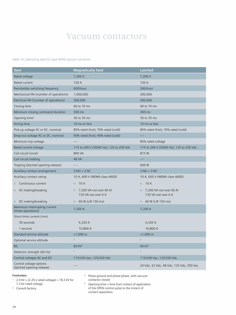
Table 16: Operating data for type 96H6 vacuum contactor
Footnotes:1. 2.0 kV + (2.25 x rated voltage) = 18.2 kV for
7.2 kV rated voltage.2. Consult factory.
3. Phase-ground and phase-phase, with vacuum contactor closed.
4. Opening time = time from instant of application of the OPEN control pulse to the instant of contact separation.
24

Vacuum contactors
Item Magnetically held
Rated voltage 13,800 V
Rated current 300 A
Permissible switching frequency 60/hour
Mechanical life (number of operations) 1,000,000
Electrical life (number of operations) 500,000
Closing time 40 to 60 ms
Minimum closing command duration 300 ms
Opening time2 <100 ms
Arcing time 11 ms or less
Pick-up voltage AC or DC, nominal 85% rated (hot); 70% rated (cold)
Drop-out voltage AC or DC, nominal <70% E
Rated control voltage 115 to 240 V (50/60 Hz); 125 to 250 Vdc
Coil circuit inrush 1,200 W
Coil circuit holding 200 W
Tripping (latched opening release) ----
Auxiliary contact arrangement 4 NO + 4 NC; 6 NO + 6 NC; 8 NO + 8 NC
Auxiliary contact rating
Continuous current
Switching ratings (ac) (AC-11)
Switching ratings (dc) (DC-11)
10 A, 600 V (NEMA class A600)
10 A
10 A@48 V; 9 A@60 V; 5 A@110 V; 2.5 A@220 V
10 A@24 V; 9 A@48 V; 7 A@60 V; 4 A@110 V; 2 A@220 V
Maximum interrupting current (three operations) 3,000
Short-time current (rms)
30 seconds
1 second
4,800 A
8 kA
Standard service altitude 50 m below to 1,000 m above sea level
Optional service altitude 4,500 m1
BIL 95 kV5
Dielectric strength (60 Hz) 3
Control voltages AC and DC 120/240 Vac; 125/220 Vdc
Control voltage options (latched opening release) ----
Table 17: Operating data for type 3TL714 vacuum contactor
Footnotes:1. High-altitude vacuum contactor required for
altitude over 1,000 m. Maximum altitude 4,500 m.
2. Opening time = time from instant of application of the OPEN control pulse to the instant of contact separation.
3. 2.0 kV + (2.25 x rated voltage) = 33.0 kV for 13.8 kV rated voltage.
4. Vacuum contactor only. Ratings for installation are determined by fuses.
5. Phase-ground and phase-phase, with vacuum contactor closed.
25

Fuse applications
For non-motor loads
The principal application for ANSI "E" rated fuses in Series 81000 controllers is for non-rotating loads, such as transformer feeders. The following tabulation may be used for estimating the "E" rated fuse appropriate for a particular three-phase transformer application.
Fuse ratings higher or lower than those listed in Table 18 may need to be employed if the transformer has unusual magnetizing (inrush) current characteristics, or for proper coordination with the secondary protective device (for example, secondary fuse, low-voltage circuit breaker trip device, overcurrent relay, etc.). Transformer overload capability may also have a bearing on fuse selection. However, this table is accurate for most typical transformer feeder applications.
The "E" rated fuses have the same interrupting current ratings as the type FM or A720R "R" rated fuses. Both are rated at 50 kA symmetrical and 80 kA asymmetrical interrupting. High continuous current fuses (for instance, 600E through 1350E) are type CLE-750, and interrupting current is 31.5 kA to 40 kA depending on fuse size.
All medium-voltage controllers employ current-limiting fuses for short-circuit protection. The term "current limiting" is derived from the operating characteristics of the fuse. Figure 20 shows graphically how, for maximum fault levels, the fuse operates within the first one-quarter cycle of short-circuit current. This limits the energy "let thru" well below peak values, thus providing "current limitation."
The type 3TL71 vacuum contactor is intended for motor applications and is not available in a mechanically latched version. Therefore, transformer protection fuses for this contactor are not shown in Tables 18-19.
Figure 20: Current limiting effect
Current
Fuse melting
Arcing
Wave of available symmetrical short-circuit current
Ip = let-through current
26

Fuse applications
Transformer Fuse size1
kVA three-phase
2.4 kV 4.16 kV 4.8 kV 6.9 kV
45 25E 10E 10E ----
75 30E 15E 15E 10E
112.5 40E 20E 20E 15E
150 50E 30E 25E 20E
225 80E 40E 40E 25E
300 100E 65E 50E 40E
500 200E 100E 80E 65E
750 250E 150E 125E 100E
1,000 400E 200E 200E 125E
1,500 450E 300E 250E 200E
2,000 ---- 400E 350E ----2
2,500 ---- ---- 450E ----2
3,000 ---- ---- 450E ----2
Table 18: Typical fuse sizes for transformer protection
Table 19: Typical fuse sizes for motor protection
Footnote:1. Fuse sizes are based on 133
percent overload capacity, except 1,500 kVA at 2.4 kV, 2,500 kVA at 4.16 kV and 3,000 kVA at 4.8 kV.
2. Consult factory.
Maximum design voltage kV
Current designation
Continuous current at 40 °C
Minimum interrupting capability
Interrupting rating 50/60 Hz
5,080 2R (one barrel) 70 190 Single-phase 80 kA rms asymmetrical (210 MVA at 2.4 kV; 415 MVA at 4.8 kV)
3R 100 225
4R 130 330
6R 170 500
9R 200 740
12R 230 955
18R (two barrel) 390 1,440
24R 450 1,910
38R 600 3,000
57X (three barrel) 900 4,500
7,200 2R (one barrel) 70 190 Single-phase 80 kA rms asymmetrical (620 MVA at 7.2 kV)
3R 100 225
4R 130 330
6R 170 500
9R 200 740
12R 230 955
18R (two barrel) 390 1,440
24R 450 1,910
38R 600 3,000
48X 750 3,500
57X 900 4,500
27
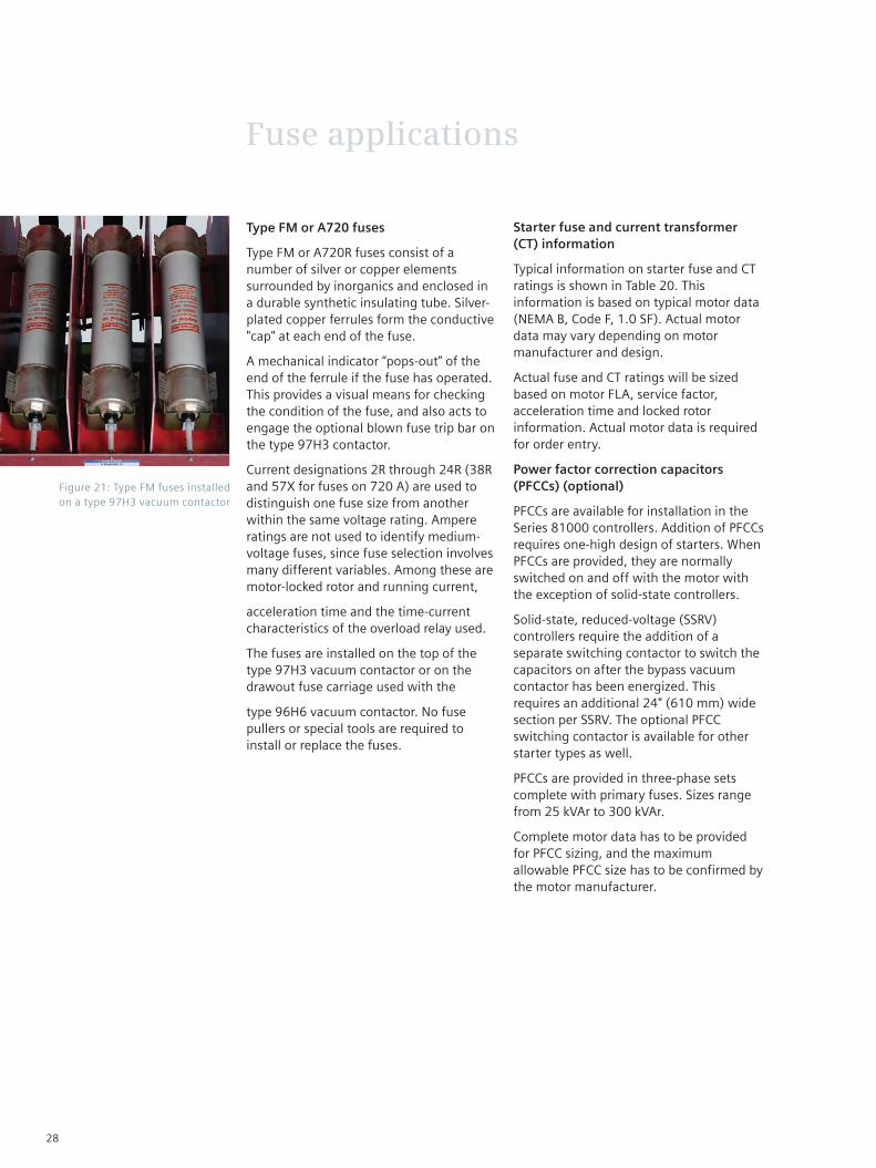
Type FM or A720 fuses
Type FM or A720R fuses consist of a number of silver or copper elements surrounded by inorganics and enclosed in a durable synthetic insulating tube. Silver-plated copper ferrules form the conductive "cap" at each end of the fuse.
A mechanical indicator “pops-out” of the end of the ferrule if the fuse has operated. This provides a visual means for checking the condition of the fuse, and also acts to engage the optional blown fuse trip bar on the type 97H3 contactor.
Current designations 2R through 24R (38R and 57X for fuses on 720 A) are used to distinguish one fuse size from another within the same voltage rating. Ampere ratings are not used to identify medium-voltage fuses, since fuse selection involves many different variables. Among these are motor-locked rotor and running current,
acceleration time and the time-current characteristics of the overload relay used.
The fuses are installed on the top of the type 97H3 vacuum contactor or on the drawout fuse carriage used with the
type 96H6 vacuum contactor. No fuse pullers or special tools are required to install or replace the fuses.
Fuse applications
Starter fuse and current transformer (CT) information
Typical information on starter fuse and CT ratings is shown in Table 20. This information is based on typical motor data (NEMA B, Code F, 1.0 SF). Actual motor data may vary depending on motor manufacturer and design.
Actual fuse and CT ratings will be sized based on motor FLA, service factor, acceleration time and locked rotor information. Actual motor data is required for order entry.
Power factor correction capacitors (PFCCs) (optional)
PFCCs are available for installation in the Series 81000 controllers. Addition of PFCCs requires one-high design of starters. When PFCCs are provided, they are normally switched on and off with the motor with the exception of solid-state controllers.
Solid-state, reduced-voltage (SSRV) controllers require the addition of a separate switching contactor to switch the capacitors on after the bypass vacuum contactor has been energized. This requires an additional 24" (610 mm) wide section per SSRV. The optional PFCC switching contactor is available for other starter types as well.
PFCCs are provided in three-phase sets complete with primary fuses. Sizes range from 25 kVAr to 300 kVAr.
Complete motor data has to be provided for PFCC sizing, and the maximum allowable PFCC size has to be confirmed by the motor manufacturer.
Figure 21: Type FM fuses installed on a type 97H3 vacuum contactor
28

Fuse applications
Table 20: NEMA design B motor characteristics4
HP3 2.3 kV1 4.16 kV1 6.9 kV1 13.2 kV1
FLA2 Fuse size5
CT ratio
FLA2 Fuse size5
CT ratio
FLA2 Fuse size
CT ratio
FLA2 Fuse size5
CT ratio
60 16.5 2R 25:5 ---- ---- ---- ---- ---- ---- ---- ---- ----
75 19.7 2R 25:5 ---- ---- ---- ---- ---- ---- ---- ---- ----
100 25.8 2R 40:5 ---- ---- ---- ---- ---- ---- ---- ---- ----
125 31.0 3R 50:5 ---- ---- ---- ---- ---- ---- ---- ---- ----
150 36.6 3R 50:5 20.3 2R 40:5 ---- ---- ---- ---- ---- ----
200 47.3 4R 75:5 26.3 2R 40:5 15.9 2R 25:5 ---- ---- ----
250 58.3 4R 100:5 32.3 3R 50:5 21.0 2R 30:5 ---- ---- ----
300 69.6 6R 100:5 38.6 3R 75:5 24.5 2R 40:5 ---- ---- ----
350 81.0 6R 150:5 44.9 4R 75:5 29.0 3R 40:5 ---- ---- ----
400 91.1 9R 150:5 50.5 4R 75.5 32.5 3R 50:5 ---- ---- ----
450 102 9R 150:5 56.5 4R 75.5 36.0 3R 50:5 ---- ---- ----
500 113 9R 150:5 62.5 6R 100.5 40.0 3R 75:5 ---- ---- ----
600 134 12R 200:5 74.6 6R 100:5 48.0 4R 75:5 ---- ---- ----
700 156 12R 300:5 86.5 6R 150:5 56.0 4R 75:5 ---- ---- ----
800 177 12R 300:5 98.3 9R 150:5 63.0 6R 100:5 ---- ---- ----
900 199 18R 300:5 110 9R 150:5 67.5 6R 100:5 ---- ---- ----
1,000 220 18R 300:5 122 12R 200:5 77 6R 100:5 40 80E 75:5
1,250 275 24R 400:5 152 12R 200:5 96 9R 150:5 50 100E 75:5
1,500 328 24R 600:5 182 12R 300:5 112 9R 150:5 60 125E 75:5
1,750 382 24R 600:5 212 18R 300:5 130 12R 200:5 70 125E 100:5
2,000 436 36R 800:5 241 18R 400:5 153 12R 200:5 80 150E 100:5
2,250 490 36R 800:5 271 24R 400:5 171 12R 250:5 90 150E 150:5
2,500 534 48X 800:5 300 24R 400:5 188 12R 250:5 100 200E 150:5
3,000 643 57X 1,000:5 359 24R 600:5 224 18R 300:5 120 200E 150:5
3,500 ---- ---- ---- 418 36R 600:5 262 24R 400:5 140 250E 200:5
4,000 ---- ---- ---- 477 36R 800:5 299 24R 400:5 160 250E 200:5
4,500 ---- ---- ---- 550 48X 800:5 316 38R 500:5 179 300E 250:5
5,000 ---- ---- ---- 611 57X 1,000:5 355 38R 500:5 199 300E 250:5
5,500 ---- ---- ---- 678 57X 1,000:5 395 47X 600:5 220 300E 300:5
Footnotes:1. Three-phase, 60 Hz.2. Full-load amperage is abbreviated FLA.3. Horsepower is abbreviated HP.4. Consult Siemens for motor sizes or voltages not
shown.5. Fuse sizes are based on enclosed continuous
current rating, one start from ambient, a coast to stop and a second start.
29

Dimensions
Table 21: Floor plan dimensions in inches (mm)
A B C D E F G H
90.0 (2,286)
36.0 (915)
32.8 (832)
31.0 (787)
21.9 (556)
1.1 (28)
4.7 (119)
2.1 (54)
I J K L M N O P
34.9 (887)
10.1 (256)
6.1 (154)
4.4 (112)
3.5 (89)
2.9 (73)
29.5 (749)
68.5 (1,740)
Q R1 S T U V W X
32.5 (826)
10.0/13.0 (254)/((330)
28.8 (731)
4.0 (102)
3.8 (95)
32.8 (832)
18.8 (478)
4.2 (106)
Footnote:1. 3,000 main bus.
Figure 22: Typical floor plan details for class E2 medium-voltage controllers
B
Front view Side view
B
A
Front Rear
B
Low-voltage compartment
Bus barrier
BA
C
G
Horizontal bus
A
Front Rear
B
BA C
GS
30

Dimensions
Figure 23: Top view and typical floor plan with bus located in top compartment - dimensions in inches (mm)
A B C D E F G H
90.0 (2,286)
36.0 (915)
32.8 (832)
31.0 (787)
21.9 (556)
1.1 (28)
4.7 (119)
2.1 (54)
I J K L M N O P
34.9 (887)
10.1 (256)
6.1 (154)
4.4 (112)
3.5 (89)
2.9 (73)
29.5 (749)
68.5 (1,740)
Q R1 S T U V W X
32.5 (826)
10.0/13.0 (254)/((330)
28.8 (731)
4.0 (102)
3.8 (95)
32.8 (832)
18.8 (478)
4.2 (106)
Figure 24: Top view and typical floor plan with bus located in top-hat compartment - dimensions in inches (mm)
Top view
P
D
E
G
Q
L
M Center line of conduit maximum
Nominal rigid conduit size 3" (76) for control wires
For T1, T2 and T3 to bottom compartment
For T1, T2 and T3 to middle compartment
Nominal rigid conduit size 4" (102) for control wires
B
B
BI
K J
.625 (16) diameter two holes for sill anchor bolts when required (one front, one rear)
CD
E
G
L
M
B
H
Nominal rigid conduit size 3" (76) for control wires
For T1, T2 and T3 to middle or L1, L2 and L3 to top compartment
For T1, T2 and T3 to bottom compartment
Nominal rigid conduit size 4" (102) for control wires
Floor plan
Center line of conduit maximum
N
O
.625 (16) diameter four holes for sill anchor bolts
Top view
P
S
T
Q
T
M
Conduit for control wire
For T1, T2 and T3 to top compartment
For T1, T2 and T3 to middle compartment
All conduits maximum rigid size 3.5" (89) for control wires
B
B
BI
K J
.625 (16) diameter two holes for sill anchor bolts when required (one front, one rear)
VD
W
X
X
B
H
Nominal rigid conduit size 3" (76) for control wires
For T1, T2 and T3 to middle compartment
For T1, T2 and T3 to bottom compartment
Nominal rigid conduit size 3.5" (89)
Floor plan
Center line of conduit maximum
N
O
.625 (16) diameter four holes for sill anchor bolts
V
For T1, T2 and T3 to bottom compartment
X
For T1, T2 and T3 to top compartment
Dimensions
31

Table 22: Dimensions and weights
Controller Qty. of cont.7
Dimensions in inches (mm)
Weight in lbs (kg)
Layout
NEMA 1, 1A or 12 NEMA 3R walk-in
NEMA 3R non-walk-in
NEMA 1 or 12
N3R
Type Rating Height Width Depth Width Width
Induction, full-voltage, non-reversing, (FVNR) drawout
5 kV 360 A 1 30 (762) 36 (915) 36 (915) 42 (1,067) 42 (1,067) 1,400 (635) 1,600 (726) 1
5 kV 720 A 1 36 (915) 36 (915) 36 (915) 42 (1,067) 42 (1,067) 1,600 (726) 1,800 (817) 2
7 kV 360 A 1 90 (2,286)1 36 (915) 36 (915) 42 (1,067) 42 (1,067) 1,500 (681) 1,700 (772) 3/16
7 kV 720 A 1 90 (2,286)1 36 (915) 36 (915) 42 (1,067) 42 (1,067) 1,600 (726) 1,800 (817) 2
15 kV 360 A 1 90 (2,286) 126 (3,201) 48 (1,220) ---- ---- 5,000 (2,268) 5,700 (2,586) 29
Reduced-voltage, primary reactor, non-reversing, (RVPR) drawout
5kV 360 A 2 90 (2,286) 60 (1,524)/ 72 (1,829)
36 (915) 78 (1,982) 78 (1,982) 4,000 (1,815)/ 6,800 (3,085)
4,400 (1,996)/ 7,200 (3,266)
4
5 kV 720 A 2 90 (2,286) 96 (2,439)/ 108 (2,744)
36 (915) 114 (2,896) 120 (3,048) 7,400 (3,357)/ 8,800 (3,992)
7,800 (3,538)/ 9,200 (4,173)
5
7 kV 360 A 2 90 (2,286) 72 (1,829)/ 96 (2,439)
36 (915) 78 (1,982)/ 114 (2,896)
120 (3,048) 4,600 (2,087)/ 6,800 (3,085)
5,000 (2,268)/ 7,800 (3,538)
6
7 kV 720 A 2 90 (2,286) 2 36 (915) 2 2 2 2 5
Reduced-voltage, auto-transformer, non-reversing, (RVAT) drawout
5kV 360 A 3 90 (2,286) 60 (1,524)/ 72 (1,829)
36 (915) 78 (1,982) 78 (1,982) 4,200 (1,905)/ 7,000 (3,175)
4,600 (2,087)/ 7,400 (3,357)
7
5 kV 720 A 3 90 (2,286) 96 (2,439)/ 108 (2,744)
36 (915) 114 (2,896) 120 (3,048) 7,600 (3,447)/ 9,000 (4,082)
8,200 (3720)/ 9,600 (4,355)
8
7 kV 360 A 3 90 (2,286) 72 (1,829)/ 96 (2,439)
36 (915) 78 (1,982)/ 114 (2,896)
120 (3,048) 4,800 (2,177)/ 6,800 (3,084)
5,400 (2,449)/ 8,200 (3,720)
9
7 kV 720 A 3 90 (2,286) 2 36 (915) 2 2 2 2 9
Induction, full-voltage, non-reversing, (FVNR) drawout
5 kV 360 A 3 90 (2,286) 36 (915) 36 (915) 42 (1,067) 42 (1,067) 1,800 (817) 2,000 (907) 10
5 kV 720 A 3 90 (2,286) 72 (1,829) 36 (915) 78 (1,982) 78 (1,982) 3,200 (1,452) 3,600 (1,633) 11
7 kV 360 A 3 90 (2,286) 36 (915) 36 (915) 42 (1,067) 42 (1,067) 2,000 (907) 2,200 (998) 12
7 kV 720 A 3 90 (2,286) 72 (1,829) 36 (915) 78 (1,982) 42 (1,067) 3,200 (1,452) 3,600 (1,633) 11
Synchronous, reduced-voltage, auto-transformer, non-reversing (RVATS)
5 kV 360 A 3 90 (2,286) 84 (2,134)/ 108 (2,744)
36 (915) 114 (2,896) 120 (3,048) 5,100 (2,313)/ 7,900 (3,583)
5,700 (2,585)/ 8,500 (3,856)
16
5 kV 720 A 3 90 (2,286) 132 (3,353)/ 144 (3,658)
36 (915) 150 (3,810) 156 (3,962) 8,500 (3,856)/ 9,900 (4,491)
9,300 (4,218)/ 10,700 (4,853)
17
7 kV 360 A 3 90 (2,286) 132 (3,353) 36 (915) 150 (3,810) 156 (3,962) 5,700 (2,585)/ 7,900 (3,583)
6,500 (2,948)/ 9,300 (4,218)
16
7 kV 720 A 3 90 (2,286) 2 36 (915) 2 2 2 2 17
Dimensions
32

Footnotes:1. Also available in 45" (1,143 mm) high
construction for two-high arrangement and requires top-mounted bus. Consult factory.
2. Consult factory.3. Weight of drawout carriage is approximately
200 lbs (91 kg).
Controller Qty. of cont.7
Dimensions in inches (mm)
Weight in lbs (kg)
Layout
NEMA 1, 1A or 12 NEMA 3R walk-in4
NEMA 3R non- walk-in5
NEMA 1 or 12
N3R
Type Rating Height Width Depth Width Width
Induction, full-voltage, two-speed, one-winding, (2S1W) drawout
5 kV 360 A 3 90 (2,286) 36 (915) 36 (915) 42 (1,067) 42 (1,067) 2,000 (907) 2,200 (998) 21
5 kV 720 A 3 90 (2,286) 2 36 (915) 2 2 2 2 22
7 kV 360 A 3 90 (2,286) 72 (1,829) 36 (915) 78 (1,982) 78 (1,982) 3,300 (1,497) 3,700 (1,678) 23
7 kV 720 A 3 90 (2,286) 2 36 (915) 2 2 2 2 22
Induction, full-voltage, two-speed, two-winding, (2S2W) drawout
5 kV 360 A 2 90 (2,286) 36 (915) 36 (915) 42 (1,067) 42 (1,067) 1,800 (817) 2,000 (907) 18
5 kV 720 A 2 90 (2,286) 72 (1,829) 36 (915) 78 (1,982) 78 (1,982) 3,200 (1,452) 3,600 (1,633) 19
7 kV 360 A 2 90 (2,286) 72 (1,829) 36 (915) 78 (1,982) 78 (1,982) 3,000 (1,361) 3,400 (1,542) 20
7 kV 720 A 2 90 (2,286) 72 (1,829) 36 (915) 78 (1,982) 78 (1,982) 3,200 (1,452) 3,600 (1,633) 19
Latched contactor, drawout
5 kV 360 A 1 30 (762) 36 (915) 36 (915) 42 (1,067) 42 (1,067) 1,400 (635) 1,600 (726) 1
5 kV 720 A 1 90 (2,286) 36 (915) 36 (915) 42 (1,067) 42 (1,067) 1,600 (726) 1,800 (817) 2
7 kV 360 A 1 90 (2,286) 36 (915) 36 (915) 42 (1,067) 42 (1,067) 1,500 (681) 1,700 (772) 3
7 kV 720 A 1 90 (2,286) 36 (915) 36 (915) 42 (1,067) 42 (1,067) 1,700 (771) 1,900 (862) 2
Solid-state, reduced-voltage, non-reversing (SSRV) drawout
5 kV 360 A 2 90 (2,286) 36 (915) 36 (915) 42 (1,067) 42 (1,067) 1,600 (726) 1,800 (817) 24
5 kV 720 A 2 90 (2,286) 72 (1,829) 36 (915) 78 (1,982) 78 (1,982) 3,200 (1,452) 3,600 (1,633) 25
7 kV 360 A 2 90 (2,286) 72 (1,829) 36 (915) 78 (1,982) 78 (1,982) 3,200 (1,452) 3,600 (1,633) 25
7 kV 720 A 2 90 (2,286) 2 36 (915) 2 2 2 2 25
15 kV 300 A 2 90 (2,286) 96 (2,438) 66 (1,677) ---- ---- 5,000 (2,268) ---- 30
LBS8 600 A or 1,200 A unfused
5 kV/7 kV ---- 90 (2,286) 36 (915) 36 (915) 42 (1,067) 42 (1,067) 1,400 (635) 1,600 (726) 26
LBS8 600 A fused or 1,200 A/ 900E fused
5 kV/7 kV ---- 90 (2,286) 36 (915) 36 (915) 42 (1,067) 42 (1,067) 1,400 (635) 1,600 (726) 26
LBS8 1,200 A/ 1,100E fused
5 kV/7 kV ---- 90 (2,286) 72 (1,829) 36 (915) 78 (1,982) 78 (1,982) 2,200 (998) 2,600 (1,179) 27
Incoming line/main lugs only
5 kV/7 kV ---- 90 (2,286) 18 (457)/ 24 (610)/ 36 (915)
36 (915) 42 (1,067) 42 (1,067) 600 (272) 1,400 (635) 28
4. Height is 107" (2,718 mm).5 Height is 103" (2,616 mm).6. Restricted to 7 kV cable rating only.7. Number of vacuum contactors.8 Load-break switch.
Table 22: Dimensions and weights (continued)
Dimensions
33
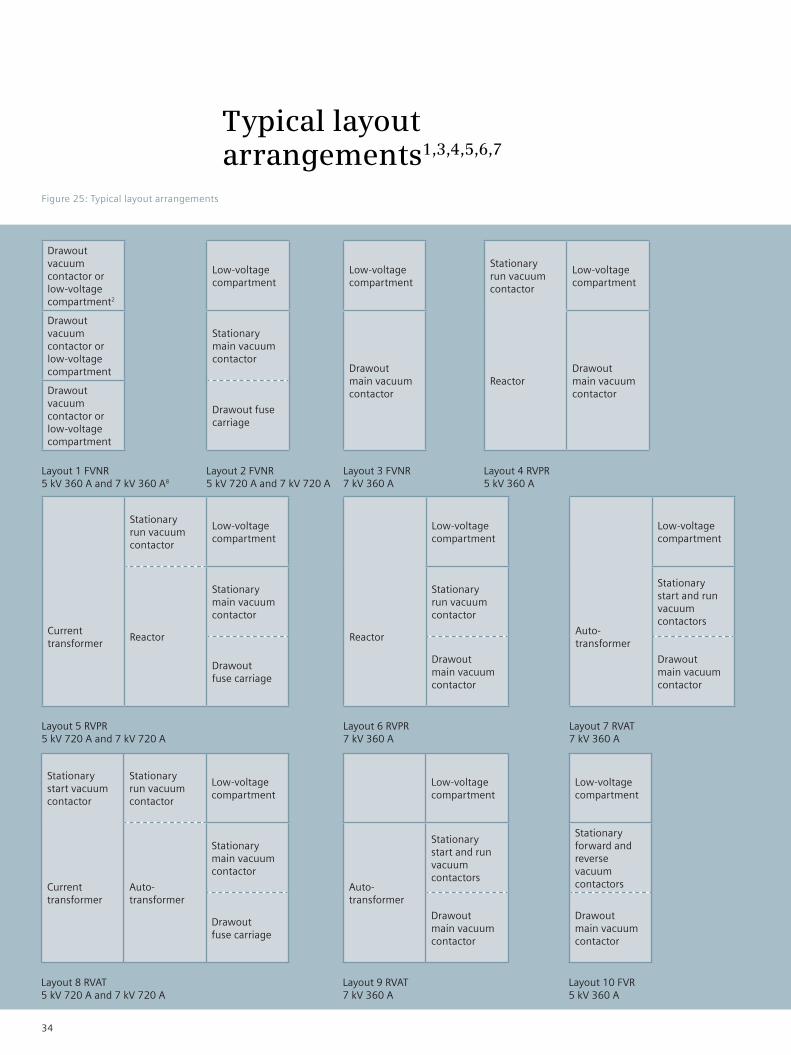
Typical layout arrangements1,3,4,5,6,7
Figure 25: Typical layout arrangements
Drawout vacuum contactor or low-voltage compartment2
Drawout vacuum contactor or low-voltage compartment
Drawout vacuum contactor or low-voltage compartment
Layout 1 FVNR 5 kV 360 A and 7 kV 360 A8
Low-voltage compartment
Stationary main vacuum contactor
Drawout fuse carriage
Layout 2 FVNR 5 kV 720 A and 7 kV 720 A
Low-voltage compartment
Drawout main vacuum contactor
Layout 3 FVNR 7 kV 360 A
Stationary run vacuum contactor
Low-voltage compartment
ReactorDrawout main vacuum contactor
Layout 4 RVPR 5 kV 360 A
Layout 5 RVPR 5 kV 720 A and 7 kV 720 A
Stationary run vacuum contactor
Low-voltage compartment
Current transformer
Reactor
Stationary main vacuum contactor
Drawout fuse carriage
Low-voltage compartment
Reactor
Stationary run vacuum contactor
Drawout main vacuum contactor
Layout 6 RVPR 7 kV 360 A
Low-voltage compartment
Auto-transformer
Stationary start and run vacuum contactors
Drawout main vacuum contactor
Layout 7 RVAT 7 kV 360 A
Layout 8 RVAT 5 kV 720 A and 7 kV 720 A
Stationary start vacuum contactor
Stationary run vacuum contactor
Low-voltage compartment
Current transformer
Auto-transformer
Stationary main vacuum contactor
Drawout fuse carriage
Low-voltage compartment
Auto-transformer
Stationary start and run vacuum contactors
Drawout main vacuum contactor
Layout 9 RVAT 7 kV 360 A
Low-voltage compartment
Stationary forward and reverse vacuum contactors
Drawout main vacuum contactor
Layout 10 FVR 5 kV 360 A
34

Typical layout arrangements1,3,4,5,6,7
Figure 25: Typical layout arrangements (continued)
Layout 11 FVR 5 kV 720 A and 7 kV 720 A
Layout 12 FVR 7 kV 360 A
Layout 13 FVNRS 5 kV 360 A
Low-voltage compartment
Space for field excitation equipment
Drawout main vacuum contactor
Layout 14 FVNRS 5 kV 720 A and 7 kV 720 A
Low-voltage compartment
Space for field excitation equipment
Stationary main vacuum contactor
Drawout fuse carriage
Layout 15 FVNRS 7 kV 360 A
Low-voltage compartment
Space for field excitation equipment
Drawout main vacuum contactor
Layout 16 RVATS 5 kV 360 A and 7 kV 360 A
Layout 17 RVATS 5 kV 720 A and 7 kV 720 A
(Standard) stationary start and run vacuum contactors
Low-voltage compartment
Space for field excitation equipment
Auto-transformer
(Alternate) stationary start and run vacuum contactors
Drawout main vacuum contactor
Layout 18 2S2W 5 kV 360 A9
Stationary reverse vacuum contactor
Low-voltage compartment
Stationary main vacuum contactor
Stationary forward vacuum contactor
Drawout fuse carriage
Low-voltage compartment
Stationary forward and reverse vacuum contactor
Drawout main vacuum contactor
Stationary start vacuum contactor
Stationary run vacuum contactor
Low-voltage compartment
Space for field excitation equipment
Current transformer
Auto-transformer
Stationary main vacuum contactor
Drawout fuse carriage
Low-voltage compartment
Drawout slow-speed vacuum contactor
Drawout fast-speed vacuum contactor
Layout 19 2S2W 5 kV 720 A and 7 kV 720 A9
Low-voltage compartment
Low-voltage compartment
Stationary slow-speed vacuum contactor
Stationary fast-speed vacuum contactor
Drawout fuse carriage
Drawout fuse carriage
35
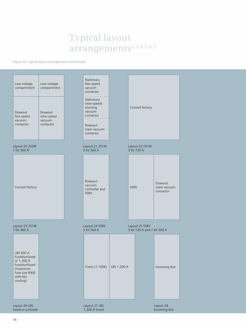
Typical layout arrangements1,3,4,5,6,7
Figure 25: Typical layout arrangements (continued)
Low-voltage compartment
Low-voltage compartment
Drawout fast-speed vacuum contactor
Drawout slow-speed vacuum contactor
Layout 20 2S2W 7 kV 360 A9
Stationary fast-speed vacuum contactor
Stationary slow-speed/shorting vacuum contactor
Drawout main vacuum contactor
Layout 21 2S1W 5 kV 360 A
Layout 22 2S1W 5 kV 720 A
Layout 23 2S1W 7 kV 360 A
SSRVDrawout main vacuum contactor
Layout 25 SSRV 5 kV 720 A and 7 kV 360 A
Layout 27 LBS 1,200 A fused
Incoming line
Layout 28 Incoming line
Consult factory
Drawout vacuum controller and SSRV
Layout 24 SSRV 5 kV 360 A
LBS 600 A fused/unfused or 1,200 A fused/unfused (maximum fuse size 900E with fan cooling)
Layout 26 LBS fused or unfused
Fuses (1,100E) LBS 1,200 A
Consult factory
36

Typical layout arrangements1,3,4,5,6,7
Figure 25: Typical layout arrangements (continued)
Outgoing cable
Drawout fuse carriage and stationary main vacuum contactor
Incoming cable
Layout 29 FVNR 15 kV
Layout 30 SSRV 15 kV
SCR chassis SCR chassis
Drawout fuse carriage and stationary main and bypass vacuum contactors
Incoming cables
Footnotes for layouts 1 through 30:1. FVNR = Full-voltage, non-reversing
RVPR = Reduced-voltage, primary reactor
RVAT = Reduced-voltage, auto-transformer
FVR = Full-voltage, reversing
FVNRS = Full-voltage, non-reversing,
synchronous
SSRV = Solid-state, reduced-voltage
LBS = Load-break switch2. When upper cell is used for a drawout contactor,
horizontal main bus (if required) is mounted
on top of unit, adding 10" (254 mm) or 13"
(330 mm) to the height of the indoor structure.
Choice of protective relays is limited. Consult
factory.
3. Weights and dimensions of reactor and auto-
transformer controllers vary as motor size
increases.4. Metering and protective device space
requirements may require an addition of a
90" (2286 mm) high x 24" (610 mm) or
36" (914 mm) wide x 36" (914 mm) deep
auxiliary structure.5. Surge protection consists of three-phase station
class arresters and surge capacitors, and requires
a 24” (610 mm) wide auxiliary incoming line
section for mounting.6. Type 3EF1 surge limiters can be provided with
any controller with no effect on layout or
dimensions.
7. Special metering and protective relaying: a
wide variety of current- and voltage-sensing
protective relays, metering devices and similar
equipment is available. Normally, the top one-
third of the structure will be devoted to a low-
voltage section housing these devices, and the
middle and lower cells will each house a FVNR
controller.8. Layout 1 for 7kV FVNR restricted to 7 kV cables
only. For 15 kV outgoing cables, use Layout 3
arrangement.9. Without mechanical interlock.
Outgoing cables
37
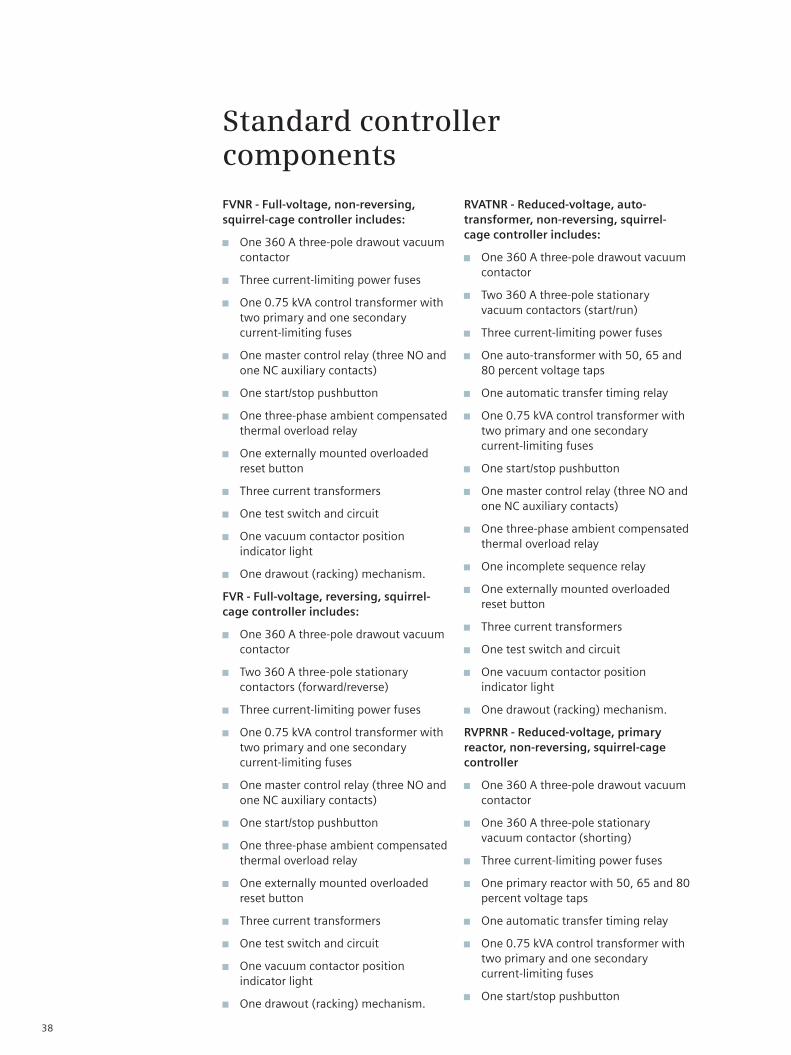
Standard controller components
FVNR - Full-voltage, non-reversing, squirrel-cage controller includes:
One 360 A three-pole drawout vacuum contactor
Three current-limiting power fuses
One 0.75 kVA control transformer with two primary and one secondary current-limiting fuses
One master control relay (three NO and one NC auxiliary contacts)
One start/stop pushbutton
One three-phase ambient compensated thermal overload relay
One externally mounted overloaded reset button
Three current transformers
One test switch and circuit
One vacuum contactor position indicator light
One drawout (racking) mechanism.
FVR - Full-voltage, reversing, squirrel-cage controller includes:
One 360 A three-pole drawout vacuum contactor
Two 360 A three-pole stationary contactors (forward/reverse)
Three current-limiting power fuses
One 0.75 kVA control transformer with two primary and one secondary current-limiting fuses
One master control relay (three NO and one NC auxiliary contacts)
One start/stop pushbutton
One three-phase ambient compensated thermal overload relay
One externally mounted overloaded reset button
Three current transformers
One test switch and circuit
One vacuum contactor position indicator light
One drawout (racking) mechanism.
RVATNR - Reduced-voltage, auto-transformer, non-reversing, squirrel-cage controller includes:
One 360 A three-pole drawout vacuum contactor
Two 360 A three-pole stationary vacuum contactors (start/run)
Three current-limiting power fuses
One auto-transformer with 50, 65 and 80 percent voltage taps
One automatic transfer timing relay
One 0.75 kVA control transformer with two primary and one secondary current-limiting fuses
One start/stop pushbutton
One master control relay (three NO and one NC auxiliary contacts)
One three-phase ambient compensated thermal overload relay
One incomplete sequence relay
One externally mounted overloaded reset button
Three current transformers
One test switch and circuit
One vacuum contactor position indicator light
One drawout (racking) mechanism.
RVPRNR - Reduced-voltage, primary reactor, non-reversing, squirrel-cage controller
One 360 A three-pole drawout vacuum contactor
One 360 A three-pole stationary vacuum contactor (shorting)
Three current-limiting power fuses
One primary reactor with 50, 65 and 80 percent voltage taps
One automatic transfer timing relay
One 0.75 kVA control transformer with two primary and one secondary current-limiting fuses
One start/stop pushbutton
38

Standard controller components
FVNRS - Full-voltage, brushless synchronous, non-reversing controller includes:
One 360 A three-pole drawout vacuum contactor
Two 360 A three-pole stationary vacuum contactors (start/run)
Three current-limiting power fuses
One auto-transformer with 50, 65 and 80 percent voltage taps
One automatic transfer timing relay
One 0.75 kVA control transformer with two primary and one secondary current-limiting fuses
One start/stop pushbutton
One master control relay (three NO and one NC auxiliary contacts)
One three-phase ambient compensated thermal overload relay
One incomplete sequence relay
One externally mounted overloaded reset button
Three current transformers
One test switch and circuit
One vacuum contactor position indicator light
One drawout (racking) mechanism.
FVMLNR - Full-voltage, mechanically latched, electrically tripped, non-reversing controller, fused includes:
One 360 A three-pole drawout vacuum contactor
Three current-limiting power fuses
One 0.75 kVA control transformer with two primary and one secondary current-limiting fuses
One close pushbutton
One open pushbutton
One master control relay (three NO and one NC auxiliary contacts)
One three-phase overcurrent relay
One manual trip external operator button
Three current transformers
One test switch and circuit
One vacuum contactor position indicator light
One drawout (racking) mechanism.
39

Standard controller components
SSRV - Solid-state, reduced-voltage, non-reversing, squirrel-cage controller includes:
One 360 A three-pole drawout main vacuum contactor
One 360 A three-pole fixed bypass vacuum contactor
Three current-limiting power fuses mounted on wheeled drawout carriage
One 2 kVA control transformer with two primary and one secondary current-limiting fuses mounted on a drawout carriage
One SCR power section
One door-mounted soft start liquid crystal display (LCD) and keypad
Three current transformers
One three-phase voltage transformer
One test switch and circuit
One vacuum contactor position indicator light
One contactor carriage racking mechanism.
The SCR logic control incorporates the following standard protection, metering and parameter adjustments:
Initial voltage (0 to 100 percent nominal voltage), factory set at 20 percent
Current limit (200 to 600 percent of motor FLA), factory set at 350 percent
Acceleration time (0 to 120 seconds), factory set at 10 seconds
Deceleration time (0 to 60 seconds), factory set at 5 seconds
Decel-final torque (0 to 10 percent sensitivity)
Pump control (four closed-loop start and stop curves)
Pulse (kick) start (0.1 to 2.0 seconds@80 line voltage)
Undervoltage trip (70 to 90 percent, adjustable trip delay)
Overvoltage trip (110 to 125 percent, adjustable trip delay 1 to 60 seconds)
Undercurrent (load loss) trip (10 to 90 percent of motor FLA, adjustable trip delay)
Allowable restarts (0 to 10, adjustable time inhibit)
Electronic overload (inverse time, 75 to 150 percent of motor FLA; two-stage programmable class 5 to 30)
Electronic shear pin (trips within one cycle of setpoint)
Phase loss (one or more phases missing)
Phase sequence (phase sequence incorrect)
Shorted SCR (internal fault detected)
Connection error (internal fault/motor connection)
Starter over temp (heatsink over temperature)
Elapsed time meter
Maximum current
Starting time for last start
Total number of starts
Cause of last fault
Percentage of current at last trip
Total number of trips
RS 485 with Modbus remote terminal unit (RTU) protocol
Opto-isolated inputs
Non-volatile memory for programming and faults
Programmable in four languages.
40

Standard controller components
Table 23: Remarks
41

Standard controller components
Table 23 Remarks (continued)
42

Standard controller components
Table 23: Remarks (continued)
43
www.usa.siemens.com/energy
Published by and copyright © 2010:Siemens AGEnergy SectorFreyeslebenstrasse 191058 Erlangen, Germany
Siemens Energy, Inc.7000 Siemens RoadWendell, North Carolina 27591 USA
For more information, contact +1 (800) 347-6659
Order No. E50001-F710-A120-X-4A00Printed in USATD 1219F BR 0410.5
All rights reserved. Trademarks mentioned in this document are the property of Siemens AG, its affiliates or their respective owners.
Subject to change without prior notice. The information in this document contains general descriptions of the technical options available, which may not apply in all cases. The required technical options should therefore be specified in the contract.