Embed Size (px)
Citation preview
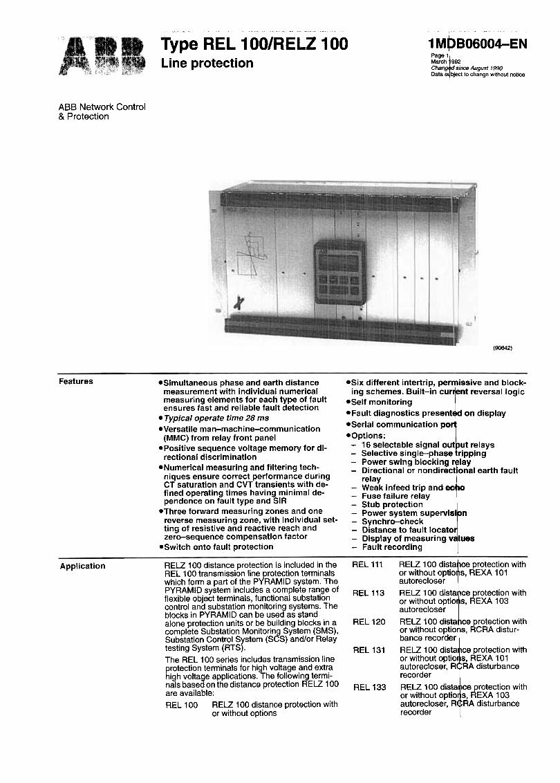
~ .., .~ Type RE L 100/RELZ 100
Line protection
1 MPBO600~EN
ABB Network Controi& Protection
(90642)
Features -Simultaneous phase and earth distancemeasurement with individual numericalmeasuring elements for each type of faultensures fast and reliable fault detection
-Typical operate time 28 ms
-Versatile man-machine-communication(MMC) from relay front panel
-Positive sequence voltage memory for di-rectional discrimination
8Numerical measuring and filtering tech-niques ensure correct performance duringCT saturation and CVT transients with de-fined operating times having minimal de-pendence on fault type and SIR
-Three forward measuring zones and onereverse measuring zone, with individual set-ting of resistive and reactive reach andzero-sequence compensation facto r
-Switch onto fault protection
-Six different intertrip, permissive and bIock-ing schemes. Built-in cur ent reversal logic
-Self monitoring-Fault diagnostics present on display-Seriai communication po
-Options:-16 selectable signal out ut relays-Selective single-phase ripping-Power swing blocking r~lay-Directional or nondirectlonal earth fault
relay-Weak infeed trip and ec o-Fuse failure relay-Stub protection-Power system supervlsi n-Synchro-check-Distance to fault locato-Display of measuring v lues-Fault recording
REL 111Application
REL 113
REL120
REL 131
REL133
RELZ 100 dista ce protection withor without optio s, REXA 101autorecloser
RELZ 100 dista ce protection withor without optio s, REXA 103autorecloser
RELZ 100 dista ce protection withor without optio s, RCRA distur-bance recorder
RELZ 100 dista ce protection withor without optio s, REXA 101autorecloser, R RA disturbancerecorder
RELZ 100 dista ce protection withor without optio s, REXA 103autorecloser, R RA disturbancerecorder
RELZ 100 distance protection is included in theREL 100 transmission line protection terminalswhich form a part of the PYRAMID system. ThePYRAMID system includes a complete range offlexible object terminals, functional substationcontroi and substation monitoring systems. Theblocks in PYRAMID can be used as standalone protection units or be building blocks in acomplete Substation Monitoring System (SMS),Substation Controi System (SCS) and/or Relaytesting System (RTS).The REL 100 series includes transmission lineprotection terminals for high voltage and extrahigh voltage applications. The following termi-nals bas ed on the distance protection RELZ 100are available:
REL 100 RELZ 100 distance protection withor with out options
page~March 992Chan since August 1990Data s bject to change wilhoul nolice
Type REL 100/RELZ 100Line protection
ASS Network Controi& Protection
IR3VC
t1I,'t/oAB
A38A
Application (confd)
~,~
~
RELZ 100 is a full scheme distance relay with Functions, such as weak infeed tri, echo logicindividual measuring elements for all types of and current reversallogic, for appl cation onfaults in all zones. The relay includes three for- parallellines, can be selected to s pplementward and one reverse measuring zone. The same of the schemes.
A built-in switch anta ault unctio provl esting of reactlve and reslstlve r,each for both instantaneous three-phase trippin for theph~s.e and ea~h fault measurlng elements, plus whole line section if the circuit-bre ker isInd!vldual settlngs for ~er.o-seque!lce.compen- closed anta a fault. The function c n be acti-~atlon, ensures an optl":1lzed appllcatlon f~r al! vated via an external input signal r via an op-I!ne lengths as weil as single and double clrcult tional current and voltage controlle logic.lines. As a complement to the quadrilate al character-
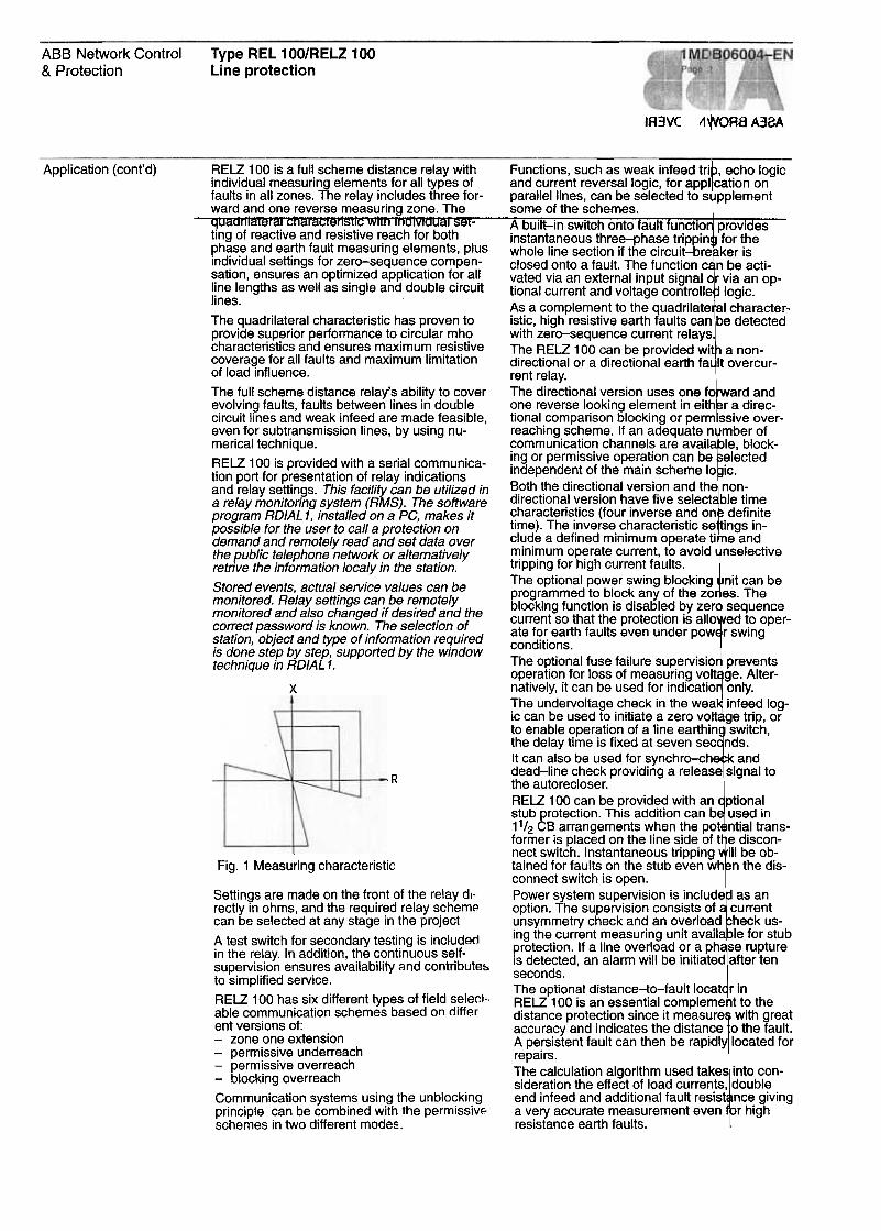
The quadrilateral characteristic has proven to istic, high resistive earth faults can be detectedprovide superior performance to circular mho with zero-sequence current relayscharacteristics and ensures m8;ximufT! r~si~tive The RELZ 100 can be provided wit a non-coverage for all faults and maximum limitation directional or a directional earth fa It overcur-of road influence. rent relay.
The full scheme distance relay's ability to cover The directional version uses one fo ard andevolving faults, faults between lines in double one reverse looking element in eith r a direc-circuit lines and weak infeed are made feasible, tional comparison blocking or perm ssive over-even for subtransmission lines, by using nu- reaching scheme. If an adequate n mber ofmerical technique. communication channels are avail le, block-RELZ 100 is provided with aseriai communica- !ng or permissive oper~tion can be .electedtian port for presentation of relay indications Independe.nt o~ the maln.scheme lo IC.
and relay settings. This faci/ity can be uti/ized in B.oth ~he dlrectl?nal verslC?n and th non:a re/ar monitoring system (RMS). The software dlreCtlona.1 ,,:erslon h~ve flye select ble tI.m.eprogram RO/AL 1, installed on a PC, makes it ,:haracterls.tlcs (four Inverse .an.d on .defl ':1 Itepossib/e for the user to call a protection on time). The Inverse characterlstlc se Ings In-demand and remote/y read and set data over cl,:!~e a defined minimum operat~ ti e and.the public te/ephone network or alternatively fT!lm~um op~rate current, to avold nselectlveretrive the information /oca/y in the station. tripping for high current faults.
.The optional power swing blocking nit can beStore:d events, actua/.servlce values can be program med to block any of the zo es. Themom.tored. Re/ay settlngs ca~ be re:mote/y blocking function is disabled by zer sequencemomtored and a/s,? changed If deslred .and the current so that the protection is allo ed to oper-corr,ect pa~sword IS known: The se(ectlon o.f ate for earth faults even under pow r swingstatIon, obJect and type of InformatIon requlred conditionsis done step by step, supported by the window technique in RO/AL 1. The o~tlonal fuse fallure sup.ervlslo prevents
operation for loss of measurlng volt ge. Alter-X natively, it can be used for indicatio only.
The undervoltage check in the wea infeed log-ic can be used to initiate a zero volt ge trip, orto enable operation of a line earthin switch,the delay time is fixed at seven sec nds.
It can ars o be used for synchro-ch k andR dead-line check providing a release signal to
.the autorecloser.
RELZ 100 can be provided with an ptionalstub protection. This addition can b used in11/2 CB arrangements when the pot ntial trans-former is placed on the line side of t e discon-
(6004-1) nect switch. Instantaneous tripping iII be ob-; tained for faults on the stub even wh n the dis-
connect switch is open.
Power system supervision is include as an.) option. The supervision consists of current
.unsymmetry check and an overload heck us-ing the current measuring unit availa le for stub
--protection. If a line overload or a ph se rupture, is detected, an alarm will be initiated after ten
OJ ) seconds.
, , The option al distance-to-fault locat r in.,' RELZ 100 is an essentiai compleme t to the'. distance protection since it measure with great
accuracy and indicates the distance o the fault.A persistent fault can then be rapidly located for
repairs.The calculation algorithm used take inta con-sideration the effect of load currents, doubleend infeed and additional fault resist nce giving
J a very accurate measurement even r highI- resistance earth faults.
:-1
Fig. 1 Measuring characteristic
Settings are made on the front of the relay dl-rectiy in ohms, and the required relay schemecan be selected at any stag e in the project
A test switch for secondary testing is includedin the relay. In addition, the continuous self-supervision ensures availability and contributes.to simplified service.
RELZ 100 has six different types of field select.able communication schemes based on different versions of:-zoneoneextension-permissive underreach-permissive overreach-blocking overreach
Communication systems using the unblockingprinciple can be combined with the permissiVE-schemes in two different modes.
Type REL 100/RELZ 100Line protection
ABB Network Controi& Protection
1 MDBO6004-ENPage 3
current values are available.
Light Emitting Diodes (LED) n the relay frontindicate relay status, start an trip. The type offault and the measuring zone involved are in-dicated on the front mounted display.
RELZ 100 provides three-ph se tripping orsingle-phase and three-pha e tripping and upto 24 relay output contacts c n be selected atsite to provide the required si nals for remoteannunciators and sequence f event recorders.
The weil structured design wi h free-standingfunctional units enables the a dition of distur-bance recorder, autorecloser nd breaker-failure units at low cost.
The fault locator option provides distance-to-fault calculation, service value measurementand fault recording data. The distance to thefault, which is calculated with high accuracy,using the weil known AANZA algorithm, andthe prefault and faulted current and voltagesare stored for the last three events and can beread off on the MMG-unit or transferred via se-rial communication to the AMS.
The primary service values for voltages, cur-rents, active power, reactive power and fre-quency can be read off on the MMC-unit oraftematively from the RMS.
For testing purposes, all secondary voltage and
Design derived from the analogue in uts received fromthe line CT's and PT's. These analogue inputsare transformed, filtered in an logue filters andpassed through the A/D conv rter. The numeri-cal signals are filtered in num rical filters beforebeing used in the calculation rocess.
The current signals are pass through resis-tive shunts to provide voltage proportional tothe input current. Total/y 10 in urs are pro-cessed in the tranformer unit LHB:-Three-phase currents-Zero sequence current-Zero sequence current fro fal/e/line-Three-phase vo/tages-Zero sequence vo/tage-One vo/tage from the bus-
The transformer unit current i puts enterthrough a plug and socket wh h automaticallyshorts out the CT input if the nit is withdrawn.
Input unit RLKD 100 contains regulated dcpower supply which provides tabilized dc tosupply the electronic circuits. his unit alsocontains 16 optocoupler input which allow ex-ternal signals to be used in th relay logic.
A/D converter unit RLLB 100 onverts the ana-logue signals produced in the ransformer unitinta numerical signals. The si nals are filteredin analogue antialiasing filters efore passingthrough a multiplexer to the converter.
RELZ 100 full scheme numerical distance relayis provided in a 19" equipment frame with aheight of 6U (10.5"). A mother board ismounted at the back of the equipment frame.All other units are of plug in type, and can beeasily removed. External connections are madewith standard COMBIFLEX terminal sockets.The "Test Switch" unit contains a test switchtype RTXP 18 or RTXP 24, a dc supply ON/OFF switch.
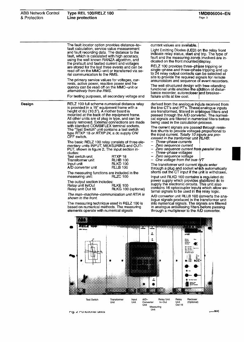
The basic RELZ 100 relay consists of three ele-mentary units INPUT, MEASURING and OUT -rUT, shown in figure 2. The input section in-cludes:Test switch unit RTXP 18Transformer unit RLHB 100Input unit RLKD 100A/D converter unit RLLB 100
The measuring functions are included in themeasuring unit: RLZC 100
The output section includes:Relay unit In/Out RLKE 100Relay unit Out 16 RLKG 100 (optional)
The man-machine-communication unit RTIA isshown in the front.
The measuring technique used in RELZ 100 isbased on numerical methods. The measuringelements operate with numerical signals
Fig. 2 Functional units (880364)
Type REL 100/RELZ 100Line protection
ABS Network Controi& Protection
1 ~DBO6004-ENpaqe 4
Design (cont'd) The numerical signals are then filtered in a mi-croprocessor which performs lowpass filtering.The total bandwidth of the filtered signals issuitable for protection purposes. The informa-tion is the n converted from paralIei mode to aserial communication mode and continues tothe measuring unit. The serial coded signalscan also be made available for remote commu-nication through an optical transmitter outlet onthe unit. A green LED on the front panel is litwhen the unit is in service.
In the measuring unit RLZC 100, the encodedsignals from the A/O converter unit are de-coded, and changed back from serial to paralIeimode, and numerical filtering is performed.
RELZ 100 uses a multiprocessor design withthree signal processors for the basic distancemeasuring function and up to three additionalsignal processors performing the optional func-tions.
The impedance measurement function is madein fault loop equations, using complex values ofvoltage, current and ch ange in current. The re-sulting impedance is compared against reac-tance and resistance limits determined by therelay setting. Three 16 bit single chip signalprocessors are used in the measuring electron-ics, the functions are as folIows:
Processor 1 Calculation of the three phase-earth loops for all zones.
Processor 2 Calculation of the three phase-phase loops for all zones.
Processor 3 Calculation of directional bound-aries for all six loops (threeph ase-earth and three ph ase-phase). The directional evalua-tion of each boundary is made inboth forward and reverse direc-tions.
In order to measure the same distance for allfaults, zero sequence compensation is appliedusing a KN facto r
Xo -X1KN = 3X1
The zero sequence compensation is applied tothe reactive reach only, and is selected sepa-rately for each zone.
The resistive reach is adjusted separately in theearth fault measuring loop and the phase faultmeasuring loop.In order to maintain definite directional mea-surement for faults close to the relaying point,the loop voltage signal is used in conjunctionwith a phase locked positive sequence memorysystem which lasts for approximately 100 mg.When the memory time expires, the directionalinformation which has been determined issealed in until fault current stops flowing. Thecircuit is the n reset when normal voltage is re-stored.LED's on the front of the unit indicate statusi.e.:Green LED: In ServiceYellow LED: StartRed LED: Trip
The man-machine-communication unit, RTIA,is plugged into the front of the measuring unit.This unit is used to set the relay, select the vari-
ous options, and present inform tion to the op-erator.
Before new settings can be ente ed, a storebutton must be operated. This e sures that set-tings will not be changed uninte tionally. Whenthe yellow or red LED's are lit, th s indicatesthat there is operation informatio stored. All ofthe information stored is automa ically shownon the display.
Loss of dc supply is indicated by the green LEDbeing dark.
The green LED will flash if there s a communi-cation failure between the meas ring unit andthe A/D converter unit. (The A/D onverter LEDwill be dark if the converter is not correct.) If theinternai supervision detects a fau t, the greenLED will flash.
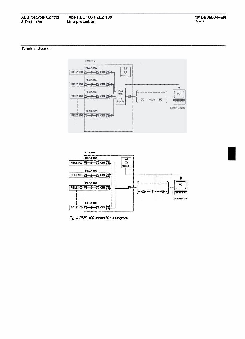
The indication of relay settings a d the changein relay settings are indicated on he digital dis-play in secondary ohms. The cho ces in set-tings and scheme configuration a e selected bycursor movement. If the self-sup ision de-tects a fault, the MMC unit can b used to local-ize the problem. Aseriai commun cation port isprovided on the back of the relay, which allowsthe MMC signals to be connected to a remoteterminal for data logging from a Ii lay monitor-ing system.For communication with RELZ 10 , two ver-sions of RMS are available. The .fference isweather the local communication etwork is anoptical star; RMS 110, or an optic Iloop, RMS160.RELZ 100 is linked to the optical etwork by anOBI-unit, RLCA 100. This unit is ptically con-nected to RELZ 100 via a plastic fibre.
For the optical RMS network plast c fibre canbe used up to a length of 30 m. Gl ss fibre canbe used for a length of maximum 00 m. Thefibre loop or star is connected to t e OBI via amodem from the SPA-ZC range.
The local telephone modem or the local PC isconnected to the opticallink by a odem, opto/RS 232. In case of a star connecti n a portex-pander is used as the gateway fro the differ-ent protections and telephone m em/PC.
The software programme, ROIAL 1 is usedboth for local and remote commun ation and isintended to be used on an IBM PC modet AT orcompatible with MS-DOS or IBM- OS version3.3 or higher.
Telephone modems and PC are n t normallyincluded in system deliveries.
The output unit RLKE 100 has a s If containedregulated dc power supply unit. Th unit con-tains 9 miniature output relays whi h providethe following output signals.
Trip R, Trip S, Trip TChannel SendGeneral TripGeneral StartStart/Block Auto-recloseZ < FailureDC Failure
A reed relay is used to provide the rrier sendoutput signal.The carrier receive, carrier guard a d block in-puts are also contained in this unit.
Type REL 100/RELZ 100Line protection
ABB Network Contral& Pratection
1 MDBO6004-ENPage 5
The basic RELZ 100 relay rovides a fullscheme distance protection with three forwardzones and one reverse 100 ng zone.
These zones can be progra med to provide sixcarrie r assisted schemes, c mplete with currentreversallogic. Switch onto fult protection isinitiated by the circuit-break r closing com-mand.
Options:The following options are av ilable by includingadditionai hardware and so are in RELZ 100
-RLKG 10016 additionai output relays an be provided togive remote indication of re ay operation.These relays are freely pro rammable andcan be selected for indicati n of any of theabout 40 avaifable internaI ignals.
-RLCA 100Fibre-optic communication odule for serialcommunication
Option 1:-Separately settable phase lection-Directional phase selection ~nd single-ph ase
tripping output for solidly ea~hed networks-Nondirectional phase select on with the fol-
lowing phase preferences f r isolated andcompensated networks:RTSR cyclic acyclicTRST cyclic acyclicRTS acyclic acyclicTRS acyclic acyclic
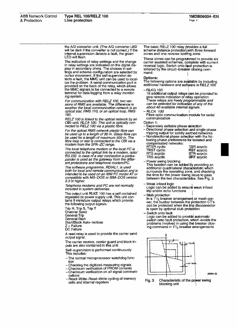
-Power swing blockingThis function can be added y providing anadditionai quadrilateral char teristic whichsurrounds the operating zon, and checkingthe time for the power swing ocus to passbetween the two characterist. See Fig. 3.
-Weak infeed logicLogic can be added to ensur weak infeedtrip and/or echo functions
-Stub grotectionIn a 11/2 breaker arrangemen or mesh cor-ner, the busbar between the rotection CT'scan be protected when the lin disconnectoris open by optional stub prote tion
-Switch onto faultLogic can be added to provid automaticswitch anta fault protection, w ich avoids theproblems involved in using th breaker clos-ing command in 11/2 breaker rrangements
the NO converter unit. (The NO converter LEDwill be dark if the converter is not correct.) If theinternai supervision detects a fault, the greenLED will flash.
The indication of relay settings and the changein relay settings are indicated on the digital dis-play in secondary ohms. The choices in set-tings and scheme configuration are selected bycursor movement. If the self-supervision de-tects a fault, the MMC unit can be used to local-ize the problem. Aseriai communication port isprovided on the back of the relay, which allowsthe MMC signals to be connected to a remoteterminal for data logging from a relay monitor-ing system.Forcommunication with RELZ 100, two ver-sions of RMS are available. The difference isweather the local communication network is anoptical star, RMS 110, or an opticalloop, RMS160.RELZ 100 is linked to the optical network by anOBI-unit, RLCA 100. This unit is opticaf/y con-nected to RELZ 100 via a plastic fibre.
For the optica/ RMS network p/astic fibre canbe used up to a length of 30 m. Glass fibre canbe used for a length of maximum 500 m. Thefibre loop or star is connected to the OBI via amodem from the SPA-ZC range.The local telephone modem or the local PC isconnected to the opticallink by a modem, opto/RS 232. In case of a star connection a portex-pander is used as the gateway from the differ-ent protections and telephone modem/PC.The software programme, RO/AL 1, is usedboth for local and remote communication and isintended to be used on an IBM PC modet AT orcompatible with MS-DOS or IBM-DOS version3.3 or higher.
Telephone modems and PC are not normalfyincluded in system deliveries.
The output unit RLKE 100 has a self containedregulated dc power supply unit. This unit con-tains 9 miniature output relays which providethe following output signals.Trip R, Trip S, Trip TChannel SendGeneral TripGeneral StartStart/Block Auto-recloseZ < FailureDC FailureA reed relay is used to provide the carrie r sendoutput signal.The carrier receive, carrier guard and block in-puts are also contained in this unit.
Self-supervision is performed continuously.This includes:-The normal microprocessor watchdog func-
tian-Checking the digitized measuring signals-Checksum verification of PROM contents-Checksum verification on all signal communi-
cations-Read-Write-Read-Write cycling of memory
cells and internai registers
Type REL 100/RELZ 100Line protection
1 MDBO6004-ENParp 6
ABB Network Controi& Protection
Design (cont'd) -Fuse failure supervisionAn internai fuse failure supervision can beprovided to avoid operation in the cage ofblown fuses
-System supervision can be achieved by ex-amining the balance and symmetry betweenthe system currents and voltages. Abnormalconditions, broken conductors, etc. can bedetected by this facility
-Synchro-check and dead-line check
Option 2:-Earth fault O/C protection
The quadrilateral characteristic operation canbe supplemented by earth fault O/C elementswhich may be nondirectional inverse or defi-nite time, or directional elements operatingwith the communication channel to provide adirectional comparison scheme.
Complementary functions:The recording module RCRA pr vides the bestcost-benefit combination when isturbancerecording is used as a complem ntary functionto the distance relay RELZ 100. he alreadyconverted numerical signals dev loped inRELZ 100 are used for disturba ce recording.The data acquisition and A/D co version iscommon to the numerical distan e relay andthe disturbance recorder.
RCRA provides complete distur nce recordingfor bay with possibility to print-o t 8 analog in-put signals (4 currents and 4 volt ges) and amaximum of 16 events.
The RELZ 100 can also be suppl ed with auto-recloser REXA.
Supporting software:RCALC Relay Calculation Progr m which en-ables a simple and accurate setti g of the dis-tance protection.
RCALC is available on 3.5" or 5. 5" floppydisks. Ordering No: RK 60100 DA.
Testplan for preparation of tests f RELZ 100with FREJA test set (RTS) on 3. "floppy disk.Ordering No: RK 912 013-CA
Option 3:-Distance to fault locator-Display of measuring values U, I, P, Q and f-Fault recording; Indication of pre-fault and
fault voltages and currents
Technical dataRated frequency, fn
Rated voltage, Un
50 or 60 Hz selectable
100/110Vac,burden 0.5 VA
< 105%Resetting ratio
Accuracy at referencecondition: Sta tic acc racy.:t5% at
85" and and0.1xUn U<1.1xUf!and 0.2 x < 1<30x /nSta tic acc racY.:t7.5%at 85" an (]' and0.03 x Un U < 0.1 x Unand 0.2 x < 1 < 30 x InSta tic ang lar accuracy.:t3" at In ,< 30 x In.:t5" at O. x In < I < InMax. dyna ic over-reach +50 at 85" and0.5 < SIR 30 a/so withGVT
typical28 s
typical 50 safter trip30 ms bet re trip
Three-ph se tripping orsingle and hree-phasetripping
90-121 V PH-PH ac90-143 V PH-PH ac
1.5 x Un2.5 x Un
1 A or 5 A,burden 0.5 VA(for In = 1 A)
Nominal range:50Hz60 Hz
Maximum vo/tage:continuousduring 1 s
Rated current, In
3x In70 x In, max. 350 A
46--60,110-125 or220-250 V, :1:20%
15 W before operation25 W after operation
Three forward zonesand ona reverse zona
Maximum current:continuousduring 1 s
Auxiliary dc voltage Operate time
Resetting timePower consumption
Tripping modeNumber of zones
Operational ambienttemperature
WeightDimensions
0.1-150.0
0.1-150.0
0.1-150.0
-S°C to + °C
Approx. 1 kg
Width 6OC 19"(483 mm)Height 6U 266 mm)Depth (23 mm)
Dielectric testCurrent circuits toother circuits and earth
Circuit to circuitor circuit to earth
KN = O, 0.1...3.0
0.0-3.0 s0.1-3.0 s0.1-3.0 s
2.5 kV, or60 Hz f in
2 kV, 50 H or60 Hz dun g 1 min (lEGPubl. 25 and ANSIG37.90)5 kV, 1.2/ ~. 0.5 J(lEG Publ. 55-5)
Impulse voltage test
Disturbance tests:Nominal frequencydisturbance test
20-100 ms in steps of5ms20% of In for all zones
Reactive reach foreach zoneOhms/phase at 1 A
Resistive reach foreach zonePhase-phaseloopsOhms/phase at 1 APhase--earthloopsOhms/loop at 1 A
Zero-sequence com-pensation facto r KN foreach zone
lime setting rangeZone 1Zone 2Zone 3
TO carrie r coordinationtime for blockingschemes
Minimum operatecurrent 500 V (5514361503)
1 MHz test 2.5 kV (IEC Publ.255-6 and ANSIC37.90a)
4-8 k\t; (SS 436 1503)
Current and vo/tage cir-cuits, auxiliary vo/tageinput and contact cir-cuits:Glass /\t; 4 kVOpto inputs:G/ass /1/, 2 kV(/EG Pub/. 255-22-4)
Trip, SignalChannel
275 V dc 275 V dc
1.0 kV dc, 800 V dc,1 min 1 min
2~ms
5-j300% of InFast transient test
Cu*rent multiplierK =10.05-1.1
fmln\= 0.05-6.0 s
0.G-\6.0 sContact data:
Max. system voltageTest voltage acrossopen contact
110~30.1 ~min. 1% of Un65°1 g
5A15A
OoSA005 A
Interrjai
30A10A
O.SAO.SA
Operate time
Earth fault overcurrent:310 ?lime characteristicLogarithmic
Normal inverse }VeryinverseExtremely inverse
Min. operate time forinverse and logarithmiccharacteristics
Definite time T 1
Directiona/ lunationRated vo/tage UBurden3UoCharacteristic ang/e
Directional or Nondirectional selectable
Distance to fault loca-tor:
Phase selection andstart
Minimum requiredmeasuring time
Setting range
1.75~ 1.25 cycles 0.1-1 O ohm for
In = 1 A8.0 A 10VAInaccuracy of distancemeasuring1.0A
0.4 A0.2A0.15A
< 2% ~t referenceconditipns
O.2A0.09 A0.04 A0.04 A
Inaccuracy ofmeasuring values:
Frequency < 0.1 forf = (O 1.05) x fn
<~/of ru = (0.1 1.8) x Un
<2%f1=(0.1 ) x In
<~/oatcoscp= 1< 5% atcos cp =.1:0.9
< 6% at s <1>= 0.8for I = ( .2-4) x In.U = (0.1 1.8) x Un
Current-carryingcapacity,continuous1 s
Making capacityinductive loadUR> 10 mg:200 ms1 s
Breaking capacity atac, max. 250 VPF > 0.4
dcUR<40ms48V110 V220 V250V
OptionsPower swing blocking:Reactive reachOhms/loop at 1 A
Resistive reachOhms/loop at 1 A
Decision time betweenouter and innercharacteristic
Switch anta fautt:
Voltage0.12-180.0
0.12-180.0 Current
Power P40 ms fixed
dc input from closingswitch
U < 25-80% of Uand I s 15%of In for0.2s
Q
Voltage and currentcheck criteria
30m ~500 m
300- bitsIs
99
25-80% of Un
20-300% of In
20-300% of In
10sfixed min. 2 14
IBM AT o % com-patibleDOS 3.3 r higher (IBMor MS)Fixed dis >20 MBFloppy di k drive 31/2"
(720 kB)640 kB P ary memoryEGANGA adapter andscreenSerialpo formodemPrinter/plo er
RMS 100 seriesMaximum fibre lengthforplastic fibre:glass fibre:
Communication speed:Number of protectionsin one loop:Number of protectionsconnected to one por-texpander
Requirements on PCand peripherials:20% of In
10sfixed
Weak end infeed tripand echo:Undervoltage UI 5,
Stub protection:Overcurrent I >
Power system overioad:Overcurrent I >
Delay time
Phase rupture:Current unbalanceDelay time
Synchro-check anddead-line check:
Frequency difference
Voltage difference
Phase deviation
Voltage at paralleling
at energizing
< 200 mHz
< 15% of Un
<450
~/icrnand Ubus > 80%
Ubus > 80% of Un
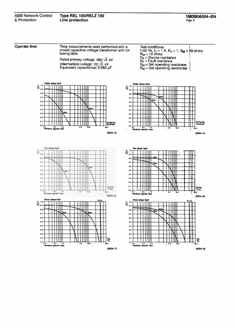
Operate time lime measurements were performed with amodel capacitive voltage transformer with fol-lowing data:
Rated primary voltage: 380/13 kV
Intermediate voltage: 22/13 kVEquivalent capacitance: 0.063 J.1F
--Test conditions:f=50 Hz, In = 1 A, Kn = 1, XM = O ohmsRM = 10 ohmsXs = Source reactanceXF = Fault reactanceXM = Set operating reactanceRM = Set operating resistance
J -;;x.-
lI.t
(6004-6)
Type REL 100/RELZ 100Line protection
1MDBO6004-ENPage 9
ABB Network Controi& Protection
Terminal diagram
RMS160
Fig. 4 RMS 100 series block diagram
Type REL 100/RELZ 100Line protection
1 r..-CBO6004-ENpaqe 10
~.~
..
!!o:_-Al- ,
[~::::'I
I'"
I,,",
ICHI~
r---153"12 eK cJ.r r--
,\-'OIP CO' '1'--TOIP (S, ", ---TOIP (T) 'I'--jm
~... TOIP --'5)"(2 DI'eElERAL STAR' --'5]"'2 DI'"ARTI8.DCk AR --'5]"(2 ,.1< FAll" --"]"(2 r;"lOSS II' AIIX - f~t.'S]"-C2 "..V1J.'AGE --,S]"-(2 Z"
'22
~
f-ST"T
START-a.OC' ..I~'llUIE~
~
I ~L___, -1~~~~ !f!I L_o L-J
~-~
~
~5) ~ICATIIII PQI1 TO
SlJBSTATIIII CONTRa. (5(5)ftN11O:L1IEO
,) SERI"- (OtIIiICAT'WI ""f(5/1S) .tEN INCLIXEO
1
-r.-,o, CAN ~ SET fM v3-Pl!ASETRIP \OEN II'TiOMAl. SIGN'"PIWCESSIR 1 I S INQ.U~C
";2j ,... , i
~IL
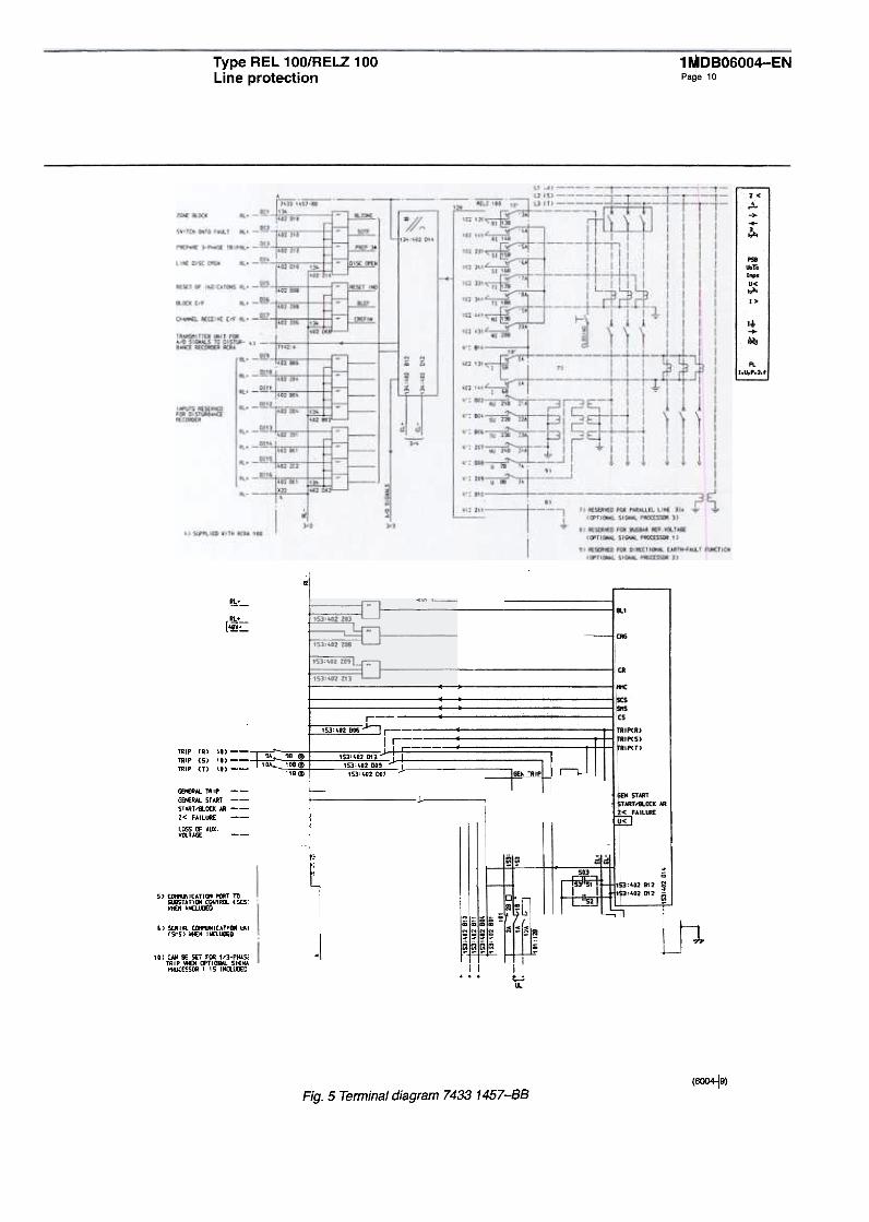
(6OO4..j9)Fig. 5 Terminal diagram 7433 1457-88
'I
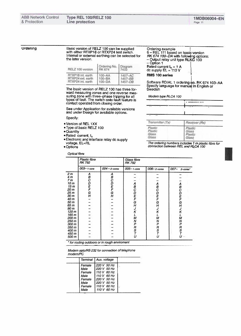
Ordering---
Basic version of RELZ 100 can be suppliedwith either RTXP18 or RTXP24 test switch.Internai or external earthing can be selected forthe later version.
Ordering No.I RK 674 IRELZ 100 version
1
1OG-AA
10G-BA
10G-OA
1457-AC1457-881457-08
--Ordering example6 -REL 111 based on basi versionRK 674 10D-OA with folio ng options:-Output relay unit type RL G 100-Option 1Rated current In = 1 Adc supply EL = 110 V
AMS 100 series
Software RDIAL 1 ordering o. RK 674 103-AASpecify language for manua in English orSwedish
Modem type RLCA 100
I Ordfring N~
[ReCf~er
~x)
The basic version of RELZ 100 has three for-ward measuring zones and one reverse mea-suring zon e with three-phase tripping for alltypes of fault. The switch onto fault feature iscontact operated from closing order.
See under Application for available versionsand under Design for available options.
Specify:
.Version of REL 1XX
.Type of basic RELZ 100
.Quantity.Rated current, In.Electronic and interface relay dc supply
voltage, EL=RL.Options
Optical fibre
The orderingnumbers fncludes t mplaSiic fibre forconnection between REL and R4CA 100
Modem optolRS 232 for connection of telephonemodem/PC
I
Termlna/rAux. VO/täge
1~~ringNO.
Fibre
1220 V 50Hz
220 V 50Hz
110 V 60 Hz110 V 60 Hz220 V 50Hz220 V 50Hz110 V 60 Hz110 V 60 Hz
l FemaJe
MaJeIFemaJeMaJe
FemaJeMaJeI
FemaJe
MaJe

Type REL 100/RELZ 100Line protection
ABB Network Controi& Protection
1 MDBO6004-ENPage 12
References 1 MDUO6004-EN1MDUO6012-EN
1 MDB10004-EN1MDB10006-EN1 MDBOOOO4-EN
RELZ 100RDIAL 1RES 100/REOR 100and RCRAREXA, AutorecloserPYRAMID