Embed Size (px)
Citation preview
1/8 Modular Valves
P T B A
P T B A
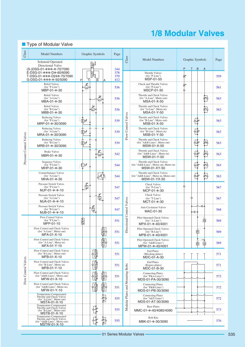
Type of Modular Valve
536
344 378 379 412
536
536
539
539
539
542
544
544
547
547
547
551
551
551
551
551
551
551
555
555
555
561
559
563
563
563
563
563
563
563
563
567
567
568
569
569
569
571
571
572
572
572
573
576
Solenoid OperatedDirectional Valve
Model Numbers Graphic Symbols Page
Cla
ss
Model Numbers Graphic Symbols Page
Cla
ss
Pre
ssur
e C
ontr
ol V
alve
sF
low
Con
trol
Val
ves
Flo
w C
ontr
ol V
alve
sD
irec
tion
al C
ontr
ol V
alve
sM
odul
ar P
late
s an
d M
ount
ing
Bol
ts
(S-)DSG-01-***-*-70/7090E-DSG-01-***-D*-60/6090T-DSG-01-***-D24*-70/7090G-DSG-01-***-*-50/5090
Pressure Switch Valves (for "B-Line")
MJB-01-*-*-10
Pressure Switch Valves (for "A-Line")
MJA-01-*-*-10
Pressure Switch Valves (for "P-Line")
MJP-01-*-*-10
Counterbalance Valves (for "A-Line")
MHA-01-*-30
Sequence Valves (for "P-Line")
MHP-01-*-30
Brake Valves
MBR-01-*-30
Reducing Valves (for "B-Line")
MRB-01-*-30/3090
Reducing Valves (for "A-Line")
MRA-01-*-30/3090
Reducing Valves (for "P-Line")
MRP-01-*-30/3090
Releif Valves (for "B-Line")
MBB-01-*-30
Releif Valves (for "A-Line")
MBA-01-*-30
Releif Valves (for "P-Line")
MBP-01-*-30
Throttle and Check Valves (for "A&B-Lines", Metre-in, Metre-out)
MSW-01-YX-50
Throttle and Check Valves (for "A&B-Lines", Metre-out, Metre-in)
MSW-01-XY-50
Throttle and Check Valves (for "A&B-Lines", Metre-in)
MSW-01-Y-50
Throttle and Check Valves (for "A&B-Lines", Metre-out)
MSW-01-X-50
Throttle and Check Valves (for "B-Line", Metre-in)
MSB-01-Y-50
Throttle and Check Valves (for "B-Line", Metre-out)
MSB-01-X-50
Throttle and Check Valves (for "A-Line", Metre-in)
MSA-01-Y-50
Throttle and Check Valves (for "A-Line", Metre-out)
MSA-01-X-50
Check and Throttle Valves (for "P-Line")
MSCP-01-30
Throttle Valves (for "P-Line")MSP-01-50
Temperature Compensated Throttle and Check Valves
(for "A&B-Lines", Metre-out)MSTW-01-X-10
Temperature Compensated Throttle and Check Valves (for "B-Line", Metre-out)
MSTB-01-X-10
Temperature Compensated Throttle and Check Valves (for "A-Line", Metre-out)
MSTA-01-X-10
Flow Control and Check Valves (for "A&B-Lines", Metre-in)
MFW-01-Y-10
Flow Control and Check Valves (for "A&B-Lines", Metre-out)
MFW-01-X-10
Flow Control and Check Valves (for "B-Line", Metre-in)
MFB-01-Y-10
Flow Control and Check Valves (for "B-Line", Metre-out)
MFB-01-X-10
Flow Control and Check Valves (for "A-Line", Metre-in)
MFA-01-Y-10
Flow Control and Check Valves (for "A-Line", Metre-out)
MFA-01-X-10
Flow Control Valves (for "P-Line")MFP-01-10
Connecting Plates (for "P&A-Lines")
MDS-01-PA-30/3090
Pilot Operated Check Valves (for "A-Line")
MPA-01-*-40/4001
Check Valves (for "P-Line")
MCP-01-*-30
Bolt Kits
MBK-01-*-30/3090
Base Plates
MMC-01-*-40/4080/4090
Anti-Cavitation Valves
MAC-01-30
End Plates (Blocking plates)
MDC-01-A-30
Check Valves (for "T-Line")
MCT-01-*-30
Pilot Operated Check Valves (for "B-Line")
MPB-01-*-40/4001Pilot Operated Check Valves
(for "A&B-Lines")MPW-01-*-40/4001
End Plates (Bypass plates)
MDC-01-B-30
Connecting Plates (for "P&B-Lines")
MDS-01-PB-30/3090Connecting Plates (for "A&T-Lines")
MDS-01-AT-30/3090
01 Series Modular Valves 535
2
1
1.2.
Special Seals for Phosphate Ester Type Fluids (Omit if not required)
F:
MBA : Relief Valve for A-Line
MBP
MBB : Relief Valve for B-Line
: Relief Valve for P-Line
-30
Design Number
*Design Standard
Refer to30
F- MBP -01 -CPres. Adj. Range
MPa (PSI)Valve Size
01
Special Seals Series Number
C: (*-2030)
H: 7-21
*-14
(1020-3050)
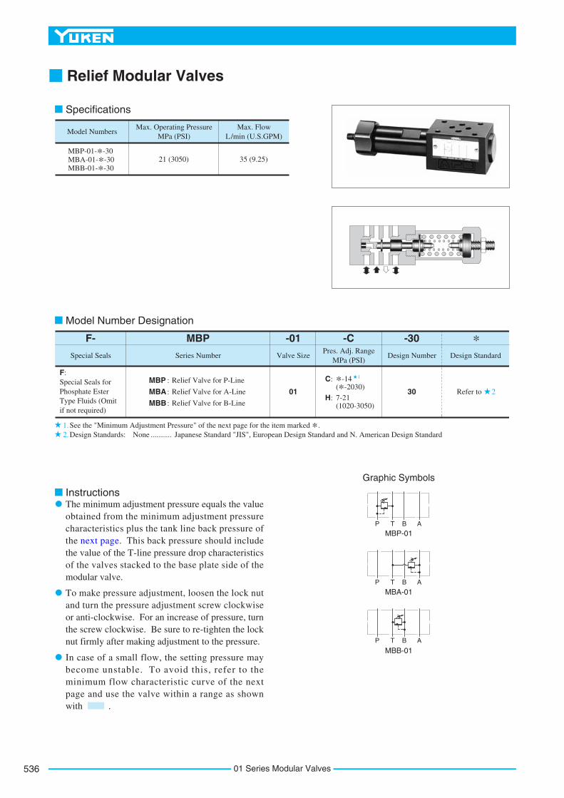
Specifications
Model Number Designation
See the "Minimum Adjustment Pressure" of the next page for the item marked *. Design Standards: None Japanese Standard "JIS", European Design Standard and N. American Design Standard...........
Instructions
Relief Modular Valves
Graphic Symbols
MBP-01
MBA-01
MBB-01
The minimum adjustment pressure equals the value obtained from the minimum adjustment pressure characteristics plus the tank line back pressure of the next page. This back pressure should include the value of the T-line pressure drop characteristics of the valves stacked to the base plate side of the modular valve.
To make pressure adjustment, loosen the lock nut and turn the pressure adjustment screw clockwise or anti-clockwise. For an increase of pressure, turn the screw clockwise. Be sure to re-tighten the lock nut firmly after making adjustment to the pressure.
In case of a small flow, the setting pressure may become unstable. To avoid this, refer to the minimum flow characteristic curve of the next page and use the valve within a range as shown with .
P T B A
P T B A
P T B A
Model Numbers
MBP-01-*-30MBA-01-*-30MBB-01-*-30
Max. Operating Pressure MPa (PSI)
Max. Flow L/min (U.S.GPM)
21 (3050) 35 (9.25)
01 Series Modular Valves536

537
MODULAR VALVES
01S
erie
sM
od
ula
rV
alve
s
F
01 Series Modular Valves
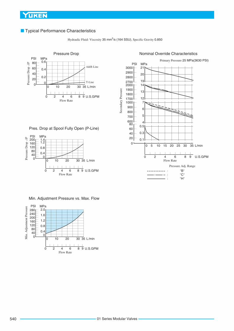
Typical Performance Characteristics
Hydraulic Fluid: Viscosity 35 mm2/s (164 SSU), Specific Gravity 0.850
L/min
U.S.GPMFlow Rate
MPaPSI
P-Line: MB -01
Pressure Drop
A B
A&B-Line
P-Line: MBP-01 T-Line
0 10 20 30 35
0 2 4 6 8 9
0
0.2
0.4
0.6
0
20
40
60
80
Minimum FlowL/minU.S.GPM
MPa
PSI
0
2
4
6
0
0.5
1.0
1.5
Min
. Flo
w
0 3.5 7 10.5 14 17.5 21
0 1000 2000 3000Pressure
Min. Adjustment Pressure
L/min
U.S.GPMFlow Rate
0
0 2 4 6 8 9
10 20 30 350
0.4
0.8
1.21.4
Min
. Adj
ustm
ent P
ress
ure
MPaPSI
04080
120160200
Nominal Override Characteristics
L/min0 10 20 30 35
U.S.GPMFlow Rate
0 2 4 6 8 9
00.81.61.52.53.5
567
121314192021
MPa
Pre
ssur
e
PSI30002800
20001800
1000800
500300
200100
0
Pre
ssur
e D
rop
P
5.5(.22) Dia. Through4 Places
Lock Nut13(.51) Hex.
Pressure Adj. Screw4(.16) Hex. Soc.
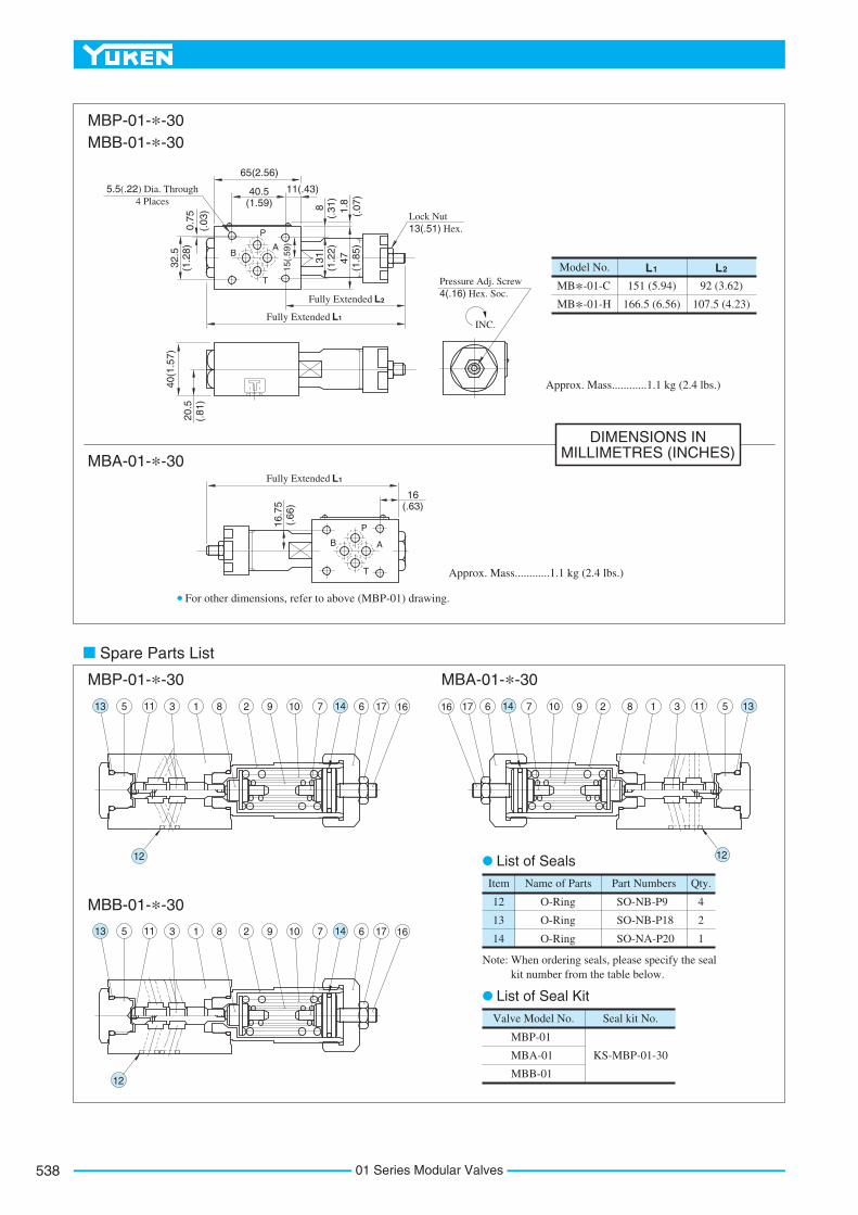
Model No.
MB*-01-C
MB*-01-H
L1 L2
151 (5.94)
166.5 (6.56)
92 (3.62)
107.5 (4.23)
Item
SO-NB-P9
SO-NB-P18
SO-NA-P20
Name of Parts Part Numbers Qty.
12
13
14
O-Ring
O-Ring
O-Ring
4
2
1
Valve Model No. Seal kit No.
MBP-01
MBA-01
MBB-01
KS-MBP-01-30
Note: When ordering seals, please specify the seal kit number from the table below.
P
BA
T
P
B A
T
For other dimensions, refer to above (MBP-01) drawing.
31(1
.22)
47(1
.85)
8(.
31)
1.8
(.07
)
LFully Extended 1
LFully Extended 2
40.5(1.59)
65(2.56)
11(.43)0.
75(.
03)
32.5
(1.2
8)
15(.
59)
20.5
(.81
)
40(1
.57)
INC.
Approx. Mass............1.1 kg (2.4 lbs.)
Approx. Mass............1.1 kg (2.4 lbs.)
16.7
5(.
66)
LFully Extended 1
16(.63)
14 17 166108 2 9 713 115 3 1
12
141716 6 10 8297 1311 531
12
14 17 166108 2 9 713 115 3 1
12
MBP-01-*-30MBB-01-*-30
MBA-01-*-30
Spare Parts List
MBP-01-*-30
MBB-01-*-30
MBA-01-*-30
List of Seals
List of Seal Kit
DIMENSIONS IN MILLIMETRES (INCHES)
01 Series Modular Valves538

539
MODULAR VALVES
01S
erie
sM
od
ula
rV
alve
s
F
01 Series Modular Valves
Instructions
Reducing Modular Valves
The minimum adjustment pressure equals the value obtained from the minimum adjustment pressure characteristics plus the tank line back pressure of the next page. This back pressure should include the value of the T-line pressure drop characteristics of the valves stacked to the base plate side of the modular valve.
If the pressure is set below 1.9 MPa (280 PSI), the maximum flow is limited. See the minimum adjustment pressure vs. maximum flow characteristics and during use, stay within the shaded zone on the graph.
To make pressure adjustment, loosen the lock nut and turn the pressure adjustment screw clockwise or anti-clockwise. For an increase of pressure, turn the screw clockwise. Be sure to re-tighten the lock nut firmly after making adjustment to the pressure.
MRP-01-*-30/3090MRA-01-*-30/3090MRB-01-*-30/3090
Model NumbersMax. Operating Pressure
MPa(PSI)Max. Flow
L/min (U.S.GPM)
31.5 (4570) 35 (9.25)
Specifications
2
1
1.2.
Special Seals for Phosphate Ester Type Fluids (Omit if not required)
F :MRP : Reducing Valve for P-Line
MRA : Reducing Valve for A-Line
-30Design Number Design Standard
Refer to30
F- MRP -01 -BPres. Adj. Range
MPa (PSI)Valve Size
01
Special Seals Series Number
MRB : Reducing Valve for B-Line
C : 3.5-14 (510-2030)*-7 (*-1020)
H : 7-21 (1020-3050)
Model Number Designation
B :
See the "Minimum Adjustment Pressure vs. Maximum Flow" of the next page for the item marked *. Design Standards: None
90Japanese Standard "JIS" and European Design StandardN. American Design Standard
........... ...............
*
MRP-01
MRA-01
MRB-01
P T B A
P T B A
P T B A
Graphic Symbols
Typical Performance Characteristics
Hydraulic Fluid: Viscosity 35 mm2/s (164 SSU), Specific Gravity 0.850
L /min
U.S.GPMFlow Rate
Primary Pressure 25 MPa(3630 PSI)
: "B": "C": "H"
Pressure Adj. Range
Pre
ssur
e D
rop
P
MPaPSI
Pressure Drop Nominal Override Characteristics
A&B-Line
000
Pres. Drop at Spool Fully Open (P-Line)
T-Line
10 20 30 35
0 2 4 6 8 9
0.2
0.4
0.6
20
40
60
80
Min. Adjustment Pressure vs. Max. Flow
L/min
U.S.GPMFlow Rate
0 10 20 30 35
0 2 4 6 8 9
MPa
00.4
0.8
1.2
1.6
2.0
04080
120160200240280PSI
Min
. Adj
ustm
ent P
ress
ure
L/min
U.S.GPMFlow Rate
0 10 20 30 35
0 2 4 6 8 9
L/min
U.S.GPMFlow Rate
0
0 5 10 15 20 25 30 35
98642
Pre
ssur
e D
rop
P MPaPSI
MPaPSI
00.4
0.1
0.3
0.54
5
6
712
13
1419
20
21
0.8
1.41.2
0
Sec
onda
ry P
ress
ure
0
20
40
60
80600
1800
2000
1700
1900
2800
3000
2700
2900
800
1000
700
900
4080
120160200
01 Series Modular Valves540

541
MODULAR VALVES
01S
erie
sM
od
ula
rV
alve
s
F
01 Series Modular Valves
Pressure GaugeConnection"C" Thd.
Spare Parts List
DIMENSIONS INMILLIMETRES (INCHES)
5.5(.22) Dia. Through4 Places
Lock Nut13(.51) Hex.
Pressure Adj. Screw4(.16) Hex. Soc.
INC.
Approx. Mass............1.1 kg (2.4 lbs.)
Item
SO-NB-P9
SO-NB-P18
SO-NA-P20
Name of Parts Part Numbers Qty.
14
15
16
O-Ring
O-Ring
O-Ring
4
2
1
Remarks
Included in Seal Kit Kit No.: KS-MBP-01-30
Model No.
MR*-01-
L1 L2
158 (6.22)
MR*-01-H
B C
173.5 (6.83)
92 (3.62)
107.5 (4.23)
Model Numbers
MR*-01-*-30
MR*-01-*-3090
Rc 1/4 = 1/4 BSP.Tr
1/4 NPT
Thread Size"C" Thd.
P
B A
T31
(1.2
2)47
(1.8
5)
8(.
31)
1.8
(.07
)LFully Extended 1
LFully Extended 2
40.5(1.59)
65(2.56)
11(.43)
0.75
(.03
)
32.5
(1.2
8)
15(.
59)
20.5
(.81
)
40(1
.57)
9 2 1 7 3 5 4 6 817 10 16 13 12
15 14
MRP-01-*-30/3090MRA-01-*-30/3090MRB-01-*-30/3090
MRP-01-*-30/3090MRA-01-*-30/3090MRB-01-*-30/3090
List of Seals
2
1
1.2.
Special Seals for Phosphate Ester Type Fluids (Omit if not required)
F:
MBR : Brake Valve
-30
Design Number
*Design Standard
Refer to30
F- MBR -01 -CPres. Adj. Range
MPa (PSI)Valve Size
01
Special Seals Series Number
C: (*-2030)
H: 7-21
*-14
(1020-3050)
Model Number Designation
See the "Minimum Adjustment Pressure "for the item marked *.Design Standards: None Japanese Standard "JIS", European Design Standard and N. American Design Standard...........
Instructions
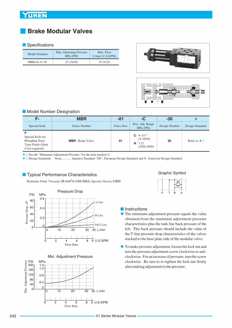
Brake Modular Valves
The minimum adjustment pressure equals the value obtained from the minimum adjustment pressure characteristics plus the tank line back pressure of the left. This back pressure should include the value of the T-line pressure drop characteristics of the valves stacked to the base plate side of the modular valve.
To make pressure adjustment, loosen the lock nut and turn the pressure adjustment screw clockwise or anti-clockwise. For an increase of pressure, turn the screw clockwise. Be sure to re-tighten the lock nut firmly after making adjustment to the pressure.
Model Numbers
MBR-01-*-30
Max. Operating Pressure MPa (PSI)
Max. Flow L/min (U.S.GPM)
25 (3630) 35 (9.25)
Specifications
Graphic Symbol
P T B A
Typical Performance CharacteristicsHydraulic Fluid: Viscosity 35 mm2/s (164 SSU), Specific Gravity 0.850
L/min
U.S.GPMFlow Rate
MPaPSIPressure Drop
A-Line
000
B-Line
20
0 2 4 6 8 9
10 20 30 35
P&T-Line
0.2
0.4
0.6
40
60
80
Min. Adjustment Pressure
Min
. Adj
ustm
ent P
ress
ure MPaPSI
00
1.4
0.4
0.8
1.2
40
80
120
160
200
L/min
U.S.GPMFlow Rate
0
0 2 4 6 8 9
10 20 30 35
Pre
ssur
e D
rop
P
01 Series Modular Valves542

543
MODULAR VALVES
01S
erie
sM
od
ula
rV
alve
s
F
01 Series Modular Valves
5.5(.22) Dia. Through4 Places
Pressure Adj. Screw4(.16) Hex. Soc.
Lock Nut13(.51) Hex.
Spare Parts List
MBR-01-*-30
MBR-01-*-30
DIMENSIONS INMILLIMETRES (INCHES)
Item
SO-NB-P7
SO-NB-P9
SO-NB-P18
SO-NA-P20
Name of Parts Part Numbers Qty.
14
15
16
17
O-Ring
O-Ring
O-Ring
O-Ring
1
4
1
1
Model No.
MBR-01-C
MBR-01-H
L1 L2
161 (6.34)
176.5 (6.95)
107 (4.21)
122.5 (4.82)
Remarks
Included in Seal Kit
Kit No.: KS-MBR-01-30
P
B A
T
31(1
.22)
47(1
.85)
8(.
31)
1.8
(.07
)
LFully Extended 1
LFully Extended 2
40.5(1.59)
65(2.56)
11(.43)
0.75
(.03
)
32.5
(1.2
8)
INC.
20.5
(.81
)
40(1
.57)
Approx. Mass............1.3 kg (2.9 lbs.)
713 14 19 5 2 1 16 10 3 12 11 17 9 8 20 21
6 15
List of Seals

2
1
1.2.
Special Seals for Phosphate Ester Type Fluids (Omit if not required)
F:
MHP
MHB : Counterbalance Valve for A-Line
: Sequence Valve for P-Line
-30
Design Number
*Design Standard
Refer to30
F- MHP -01 -CPres. Adj. Range
MPa (PSI)Valve Size
01
Special Seals Series Number
C: (*-2030)
H: 7-21
*-14
(1020-3050)
Specifications
Model Number Designation
See the "Minimum Adjustment Pressure" of the next page for the item marked *. Design Standards: None Japanese Standard "JIS", European Design Standard and N. American Design Standard...........
Instructions
Sequence Modular Valves/Counterbalance Modular Valves
Graphic Symbols
The minimum adjustment pressure (MHP-01) equals the value obtained from the minimum adjustment pressure characteristics plus the tank line back pressure of the next page. This back pressure should include the value of the T-line pressure drop characteristics of the valves stacked to the base plate side of the modular valve.
The minimum adjustment pressure (MHA-01) equals the value obtained from the minimum adjustment pressure characteristics plus the outlet-side back pressure of the valve on the next page. The outlet-side back pressure should include the values of the A-line and T-line pressure drop characteristics of the valves to be stacked due to the valve with internal drain.
MHP-01P T B A
MHA-01P T B A
To make pressure adjustment, loosen the lock nut and turn the pressure adjustment screw clockwise or anti-clockwise. For an increase of pressure, turn the screw clockwise. Be sure to re-tighten the lock nut firmly after making adjustment to the pressure.
Model Numbers
MHP-01-*-30
Max. Operating Pressure
25 (3630) 35 (9.25)
MPa (PSI)
MHA-01-*-30
Max. FlowL/min
(U.S.GPM)
35 (9.25)
Free FlowL/min
(U.S.GPM)
MHP-01
MHA-01
01 Series Modular Valves544

545
MODULAR VALVES
01S
erie
sM
od
ula
rV
alve
s
F
01 Series Modular Valves
Typical Performance Characteristics
Hydraulic Fluid: Viscosity 35 mm2/s (164 SSU), Specific Gravity 0.850
Min. Adjustment Pressure
L/min
U.S.GPMFlow Rate
0 10 20 30 35
0 2 4 6 8 9
MHP/MHA-01MPa
0
0.4
0.8
1.2
0
40
80
120
160
200PSI
Min
. Adj
ustm
ent P
ress
ure
1.4
L/min
U.S.GPMFlow Rate
0 10 20 30 35
0 2 4 6 8 9
MPaPSIPressure Drop
A&B-Line
00T-Line
0.2
0.4
0.6
20
40
60
80MHP-01
Pre
ssur
e D
rop
P
L/min
U.S.GPMFlow Rate
0 10 20 30 35
0 2 4 6 8 9
Pressure Drop for Free Flow
MHA-01MPaPSI
00
0.2
0.4
0.6
20
40
60
80
Pre
ssur
e D
rop
P
Pressure Drop
MHA-01B-Line
P&T-Line
L/min
U.S.GPMFlow Rate
0 10 20 30 35
0 2 4 6 8 9
MPaPSI
00
0.2
0.4
20
40
60
Pre
ssur
e D
rop
P

5.5(.22) Dia. Through4 Places
5.5(.22) Dia. Through4 Places
Lock Nut13(.51) Hex.
Lock Nut13(.51) Hex.
Pressure Adj. Screw4(.16) Hex. Soc.
Pressure Adj. Screw4(.16) Hex. Soc.
Approx. Mass............1.1 kg (2.4 lbs.)
Approx. Mass............1.3 kg (2.9 lbs.)
Model Numbers
MHP-01-C
MHP-01-H
L1 L2
151 (5.94)
166.5 (6.56)
92 (3.62)
107.5 (4.23)
Model Numbers
MHA-01-C
MHA-01-H
L1 L2
171 (6.73)
186.5 (7.34)
112 (4.41)
127.5 (5.02)
Item
SO-NB-P9
SO-NB-P18
SO-NA-P20
Name of Parts Part Numbers Qty.
15
16
17
O-Ring
O-Ring
O-Ring
4
2
1
Remarks
Included in Seal Kit Kit No.: KS-MBP-01-30
Item
SO-NB-P9
SO-NB-P18
SO-NB-P20
Name of Parts Part Numbers Qty.
15
16
17
O-Ring
O-Ring
O-Ring
4
2
1
Remarks
Included in Seal Kit Kit No.: KS-MHA-01-30
P
B A
T
MHP-01-*-30
MHP-01-*-30
MHA-01-*-30
MHA-01-*-30
P
B A
T
LFully Extended 1
LFully Extended 2
L1
L2
Fully Extended
Fully Extended
31 47(1
.85)
8(.
31)
1.8
(.07
)
15(.
59)
40.5(1.59)
65(2.56)
11(.43)
(1.2
2)
0.75
(.03
)
32.5
(1.2
8)20
.5(.
81)
INC.
40(1
.57)
31 47(1
.85)
8(.
31)
1.8
(.07
)
15(.
59)
40.5(1.59)
65(2.56)
11(.43)
(1.2
2)
0.75
(.03
)
32.5
(1.2
8)20
.5(.
81)
INC.
40(1
.57)
9 2 1 7 3 4 5 6 8 13 121716
15
11 104 3 1 5 9 2 6 7 8
15
16 17 12 13 14
List of Seals
Spare Parts List
List of Seals
DIMENSIONS IN MILLIMETRES (INCHES)
01 Series Modular Valves546
547
MODULAR VALVES
01S
erie
sM
od
ula
rV
alve
s
F
01 Series Modular Valves
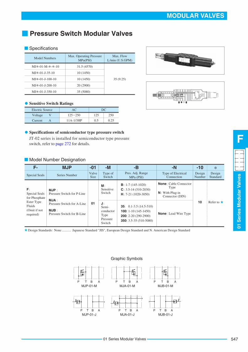
Pressure Switch Modular Valves
JT-02 series is installed for semiconductor type pressure switch, refer to page 272 for details.
Graphic Symbols
MJP-01-MP T B A
MJA-01-MP T B A
MJB-01-MP T B A
MJP-01-JP T B A P T B A P T B A
MJA-01-J MJB-01-J
Special Seals for Phosphate Ester Type Fluids (Omit if not required)
F : MJP :Pressure Switch for P-Line
-10Design Number
Design Standard
Refer to10
F- MJP -01 -BPres. Adj. Range
MPa (PSI)Valve Size
01
Special Seals Series Number
C: 3.5-14 (510-2030)
H: 7-21 (1020-3050)
Model Number Designation
B: 1-7 (145-1020)
100: 1-10 (145-1450)
200: 2-20 (290-2900)
350: 3.5-35 (510-5080)
35: 0.1-3.5 (14.5-510)
MJA :Pressure Switch for A-Line
MJB :Pressure Switch for B-Line
-MType of Switch
M :Sensitive Switch
J :Semi-conductorTypePressureSwitch
-NType of Electrical
Connection
None: Cable Connector
Type
None: Lead Wire Type
N : With Plug-in
Connector (DIN)
Model Numbers
MJ*-01-M-*-*-10
Max. Operating Pressure MPa(PSI)
Max. Flow L/min (U.S.GPM)
31.5 (4570)
MJ*-01-J-35-10 10 (1450)
MJ*-01-J-100-10 10 (1450)
MJ*-01-J-200-10 20 (2900)
MJ*-01-J-350-10 35 (5080)
35 (9.25)
Electric Source AC DC
Voltage V
Current A
125 250
11A-1/3HP
125
0.5
250
0.25
Specifications
Design Standards: None Japanese Standard "JIS", European Design Standard and N. American Design Standard...........
Sensitive Switch Ratings
Specifications of semiconductor type pressure switch
*
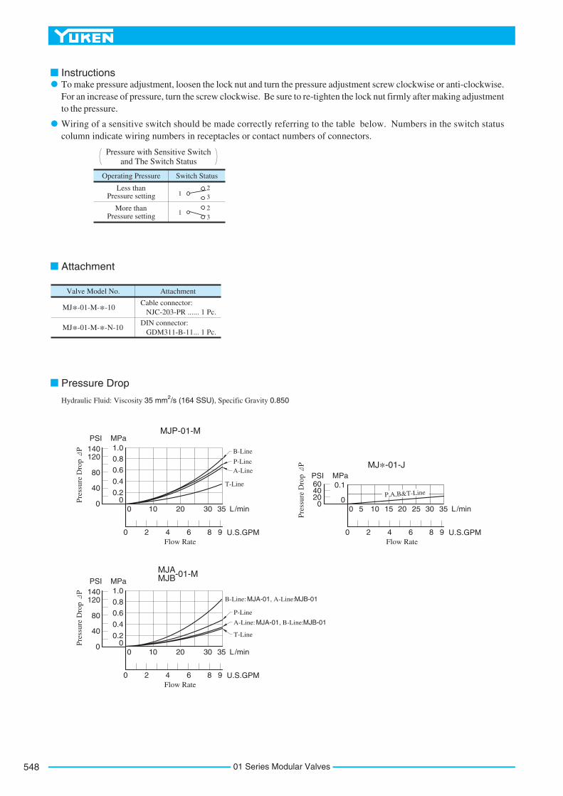
Instructions
To make pressure adjustment, loosen the lock nut and turn the pressure adjustment screw clockwise or anti-clockwise. For an increase of pressure, turn the screw clockwise. Be sure to re-tighten the lock nut firmly after making adjustment to the pressure.
Wiring of a sensitive switch should be made correctly referring to the table below. Numbers in the switch status column indicate wiring numbers in receptacles or contact numbers of connectors.
Hydraulic Fluid: Viscosity 35 mm2/s (164 SSU), Specific Gravity 0.850
Attachment
Pressure Drop
Operating Pressure Switch Status
Less than Pressure setting
More than Pressure setting
123
123
Pressure with Sensitive Switch and The Switch Status
Valve Model No. Attachment
MJ*-01-M-*-10
MJ*-01-M-*-N-10
Cable connector: NJC-203-PR ...... 1 Pc.
DIN connector: GDM311-B-11 ... 1 Pc.
L/min
U.S.GPMFlow Rate
0
B-Line
T-Line
MJP-01-M
MJ*-01-JP-LineA-Line
10 20 30 35
0 2 4 6 8 9
L/min
U.S.GPMFlow Rate
0 5 15 2510 20 30 35
0 2 4 6 8 9
MPaPSI
00
0.2
Pre
ssur
e D
rop
P
400.4
0.6
0.8
1.0
80
120140
MPaPSI
00
0.1
Pre
ssur
e D
rop
P
4020
60
L/min
U.S.GPMFlow Rate
0 10 20 30 35
0 2 4 6 8 9
MPaPSI
00
0.2
Pre
ssur
e D
rop
P
400.4
0.6
0.8
1.0
80
120140
MJA MJB-01-M
B-Line: MJA-01, A-Line: MJB-01
A-Line: MJA-01, B-Line: MJB-01
P-Line
T-Line
P,A,B&T-Line
01 Series Modular Valves548

549
MODULAR VALVES
01S
erie
sM
od
ula
rV
alve
s
F
01 Series Modular Valves
5.5(.22) Dia. Through4 Places
5.5(.22) Dia. Through4 Places
Lock Nut17(.67) Hex.
Approx. Mass............1.3 kg (2.9 lbs.)
Approx. Mass............1.3 kg (2.9 lbs.)
Approx. Mass............1.3 kg (2.9 lbs.)
MJP-01-M-*-10MJA-01-M-*-10
Cable Connector Type
B A
T
P
AP
B
T
T
AP
B
MJB-01-M-*-10
MJP-01-M-*-N-10 MJA-01-M-*-N-10
Plug-in Connector Type
MJB-01-M-*-N-10
B A
T
P
31(1
.22)
47(1
.85)
8(.
31)
1.8
(.07
)
286.5 (11.28)Fully Extended
40.5(1.59)
65(2.56)
11(.43)
32.5
(1.2
8)
15.5
(.6
1)
0.75
(.
03)
128.3(5.05)
Pressure Adjustment Screw5 (.20) Hex. Soc.
INC.
Pressure Adjustment Screw5 (.20) Hex. Soc.
INC.Lock Nut17(.67) Hex.
Cable Connector NJC-203-PR
40 (
1.57
)
20.5
(.81
)
For other dimensions, refer to "MJ -01" drawing left.
PA
Approx. Mass............1.3 kg (2.9 lbs.)
For other dimensions, refer to "MJ -01" drawing left.
PA
286.5 (11.28)Fully Extended
Fully Extended115.2 (4.54)
280.8 (11.06)Fully Extended
Fully Extended115.2 (4.54)
31(1
.22)
47(1
.85)
8(.
31)
1.8
(.07
)
62.5
(2.4
6)
53(2
.09)
39
(1.5
4)
32.5
(1.2
8)
15.5
(.6
1)
0.75
(.
03)
40.5(1.59)
65(2.56)
11(.43)
110.6 (4.35)
122.6 (4.83)
280.8 (11.06)Fully Extended
40 (
1.57
)20
.5(.
81)
Cable Departure Applicable cable:
O.D. of cable 8 - 10 mm (.31 - .39 in.)Conductor Area ... Not Exceeding 1.5 mm
2
(.0023 Sq. in.)
As shown by the dot-and-dash line, the cable departure can also be faced opposite.
DIMENSIONS IN MILLIMETRES (INCHES)

5.5(.22) Dia. Through4 Places
30(1
.18)
Dia
.
O-Ring for Port(SO-NB-P9: 4 Pcs.)
Pressure Setting Trimmer(On Trimmer)
Differential Pressure Setting Trimmer(DIFF Trimmer)
Four Conductor Cable[5 mm(.20 in.) O.D.]
RED-------Power SupplyBLACK---Power SupplyWHITE---OutputGREEN---Output
LED Indicator
Approx. Mass............1 kg (2.2 lbs.)
Approx. Mass............1 kg (2.2 lbs.)
45.5(1.79)
30(1.18)
40.5(1.59)
2000(78.7) 97(3.82)
97(3.82) 2000(78.7)
43(1.69)
40(1
.57)
20(.
79)
31(1
.22)
15.5
32.5
(1.2
8)
47(1
.85)
1.8(
.07)
Spare Parts List
MJP-01-J-*-10MJA-01-J-*-10
MJB-01-J-*-10
Semiconductor Type Pressure Switch
For other dimensions, refer to "MJ -01"
drawing left.
PA
(.61
)
8(.3
1)
0.75
(.03
)
11(.43)
65(2.56)
Item
3116-VK414239-4
3116-VK414240-2
SO-NA-P5
SO-NB-P9
Name of Parts Part Numbers Qty.
7
8
18
19
Packing
Packing
O-Ring
O-Ring
1
1
1
4
Note: When ordering seals, please specify the seal kit number from the table below.
Valve Model No. Seal Kit Numbers
MJP-01
MJA-01
MJB-01
Included in seal kit Kit No.: KS-MJP-01-10
8 21
7 8 519 12 1617
136 2 4 11 10 18 14 15 209 3 1
MJP MJA-01-M-*-N-10MJB
Cable Connector Type
Plug-in Connector Type
MJP MJA-01-M-*-10 MJB
List of Seals
List of Seal Kits
Since MJ*-01-J-*-10 (Semiconductor type pressure switch) does not have any seals inside, only four(4) O-rings for the ports are required. Please refer to the above drawing.
P
B A
T
P
B A
T
01 Series Modular Valves550

551
MODULAR VALVES
01S
erie
sM
od
ula
rV
alve
s
F
01 Series Modular Valves
Pressure and Temperature CompensatedFlow Control (and Check) Modular Valves
To make flow rate adjustment, loosen locking screw for the dial and turn the flow adjustment dial clockwise or anti-clockwise. For a decrease of flow, turn the dial clockwise. Be sure to re-tighten the locking screw firmly after the adjustment of the flow rate.
Model Number Designation
Model Numbers
MFA-01-*-10MFB-01-*-10MFW-01-*-10
Max. Operating Pressure Max. Metred Flow
L/min (U.S.GPM)
16 (2320) 35 (9.25)
MFP-01-10
MPa (PSI)
Max. Free Flow L/min (U.S.GPM)
35 (9.25)
Special Seals for Phosphate Ester Type Fluids (Omit if not required)
F : MFP : Flow Control Valve for P-Line
F- MFA
Special Seals Series Number
MFA : Flow Control and Check Valve for A-LineMFB : Flow Control and Check Valve for B-LineMFW : Flow Control and Check Valve for A&B-Lines
-10Design Number
Design
Standard
Refer to
10
-01 -XDirection of Flow
Valve Size
01
Y : Metre-inX : Metre-out
10
Graphic Symbols
Specifications
Design Standards: None Japanese Standard "JIS", European Design Standard and N. American Design Standard...........
P T B A
MFP-01
P T B AMFA-01-X
P T B AMFA-01-Y
P T B AMFB-01-X
P T B AMFB-01-Y
P T B AMFW-01-X
P T B AMFW-01-Y
Metre-out Metre-in
Instructions

Typical Performance Characteristics
Hydraulic Fluid: Viscosity 35 mm2/s (164 SSU), Specific Gravity 0.850
Min. Required Pressure Difference
L/min
U.S.GPMFlow Rate
0
MPa
0
0.4
0.8
1.0
0
80
200PSI
Dif
fere
ntia
l Pre
ssur
e
1.2
10 20 30 35
0 2 4 6 8 9
MFB-01
MFP-01
A
W
0.2
0.6
1.4
40
120
160
(Fully Open)
Turn of Flow Adj. Dial
0 1 2 3 4 5 6 7
Metred Flows vs. Dial Position
0
Flo
w R
ate
2
4
6
89
U.S.GPM L/min
0
10
20
30
35
Differential Pressure
MPa0 4 8 12 16
0 400 800 1200 1600 20002200
PSI
Min. Metred Flow
Met
red
Flo
w
3 cm /min400
300
200
100
0
cu.in/min
0
5
10
15
2022.5
SSUViscosity
0 100 200 300 400 500 600 700
Metred Flow vs. Viscosity
0 20 40 60 80 100 120 140 160 2 mm /s
Flo
w R
ate
.052
U.S.GPM L/min
0.200.220.249.69.8
10.0343536
.056
.060
.0642.552.602.659.009.259.50
Pressure Drop
L/min
U.S.GPMFlow Rate
0
0
10 20 30 35
2 4 6 8 9
MPa
00
PSI
Pre
ssur
e D
rop
P
0.1
0.2
0.3
0.4
20
4050
B-Line: MFA-01 A-Line: MFB-01
A-Line: MFP-01
B-Line: MFP-01
P&T-Line
Metred Flow vs. Differential Pres.
Flo
w R
ate
Differential Pressure
MPa0
0 400 800 1200 1600 20002200
PSI
4 8 12 16
0.9
1.0
1.1
9
10
11
33
35
37U.S.GPM L/min
.24
.26
.28
2.42.62.8
8.75
9.25
9.75
Pressure Drop for Free Flow
L/min
U.S.GPMFlow Rate
0 10 20 30 35
0 2 4 6 8 9
MPa
00
PSI
Pre
ssur
e D
rop
P
0.2
0.4
0.6
0.8
40
80
1.0120140
01 Series Modular Valves552
553
MODULAR VALVES
01S
erie
sM
od
ula
rV
alve
s
F
01 Series Modular Valves
5.5(.22) Dia. Through4 Places
5.5(.22) Dia. Through4 Places
P
B A
T
12
45
3
LOCK
89
12
0
56
89
7B A
T
89
12
0P
12
08
95
42
13 LOCK
B
T
89
12
0
A
P
B
T
89
12
0 A
P
31(1
.22)
47(1
.85)
8(.
31)
1.8
(.07
)
32 D
ia.
(1.2
6)
13(.51)40.5(1.59)
67(2.64)
32.5
(1.2
8)0.
75(.
03)
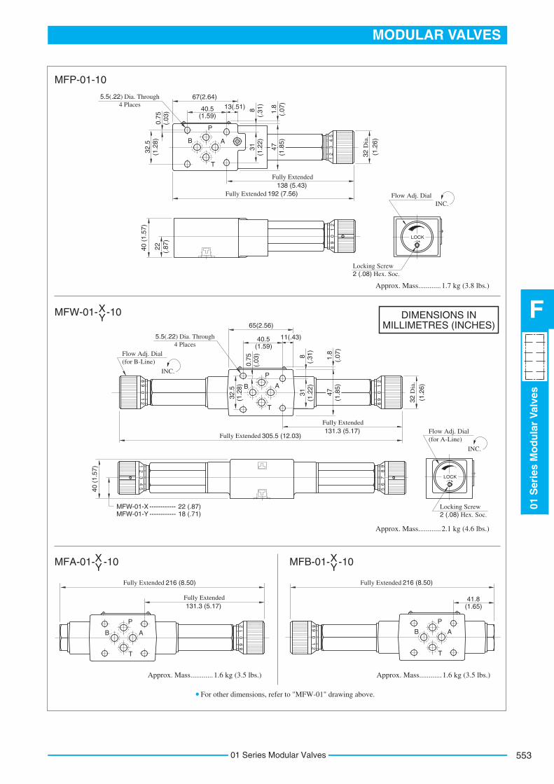
192 (7.56)Fully Extended138 (5.43)
Fully Extended
40 (
1.57
)
22 (.87
)
1.7 kg (3.8 lbs.)Approx. Mass............
Locking Screw2 (.08) Hex. Soc.
Locking Screw2 (.08) Hex. Soc.
31(1
.22)
47(1
.85)
8(.
31)
1.8
(.07
)
32 D
ia.
(1.2
6)
11(.43)40.5(1.59)
65(2.56)
0.75
(.03
)
32.5
(1.2
8)
305.5 (12.03)Fully Extended131.3 (5.17)
Fully ExtendedFlow Adj. Dial(for A-Line)
INC.
Flow Adj. Dial(for B-Line)
INC.
Flow Adj. DialINC.
2.1 kg (4.6 lbs.)Approx. Mass............
40 (
1.57
)
MFW-01-X ------------ 22 (.87) MFW-01-Y ------------ 18 (.71)
1.6 kg (3.5 lbs.)Approx. Mass............ 1.6 kg (3.5 lbs.)Approx. Mass............
216 (8.50)Fully Extended
131.3 (5.17)Fully Extended
216 (8.50)Fully Extended
41.8(1.65)
MFP-01-10
MFW-01- -10X Y
MFA-01- -10X Y MFB-01- -10X
Y
For other dimensions, refer to "MFW-01" drawing above.
DIMENSIONS IN MILLIMETRES (INCHES)

Note: When ordering seals, please specify the seal kit number from the table right.
List of Seals List of Seal Kits
Item
SO-BB-P6
SO-NA-P6
SO-NB-P9
SO-NB-P18
SO-NB-P10
Name of Parts Part NumbersMFP-01
17
18
19
20
21
Back Up Ring
O-Ring
O-Ring
O-Ring
O-Ring
1
1
4
1
1
MFA-01
1
1
4
2
MFB-01
1
1
4
2
MFW-01
2
2
4
2
Quantity
MFP-01
MFA-01
MFB-01
MFW-01
Valve Model Numbers Seal Kit Numbers
KS-MFP-01-10
KS-MFA-01-10
KS-MFW-01-10
6 19 1 7 5 2 4 11 8 9 3 12 18 17 1421
10 20 15 22 16
13
5 2010 15 1620
1 19 7 2 4 11 8 9 3 12 18 17 14 22
1 7 5 2 4 11 8 9 3 12 18 17 14
19 10 20 15 22 16
1011 21516 20
119754208931218171422 13
Spare Parts List
MFP-01-10
MFW-01- -10X Y
MFA-01- -10X Y
MFB-01- -10X Y
01 Series Modular Valves554

555
MODULAR VALVES
01S
erie
sM
od
ula
rV
alve
s
F
01 Series Modular Valves
Temperature Compensated Throttle and Check Modular Valves
Model Number Designation
Model Numbers
MSTA-01-X-10 MSTB-01-X-10 MSTW-01-X-10
Max. Operating Pressure
31.5 (4570)
MPa (PSI)
Max. Differential
Pressure
14 (2030)
MPa (PSI)
Max. Metred Flow
35 (9.25)
L/min (U.S.GPM)
Min. Metred Flow
0.5 (.13)
L/min (U.S.GPM)
Max. Free Flow
35 (9.25)
L/min (U.S.GPM)
Special Seals for Phosphate Ester Type Fluids (Omit if not required)
F
F- MSTA
Special Seals Series Number
MSTA : Temperature Compensated Throttle and Check Valve for A-Line
MSTB : Temperature Compensated Throttle and Check Valve for B-Line
MSTW : Temperature Compensated Throttle and Check Valve for A&B-Lines
-10 *Design
Standard
Refer to
-01 -X
Direction of FlowValve Size
01 X : Metre-out 10
Design Number
Design Standards: None Japanese Standard "JIS", European Design Standard and N. American Design Standard...........
:
Graphic Symbols
P T B A
MSTB-01-XP T B A
MSTA-01-XP T B A
MSTW-01-X
Specifications
InstructionsTo make flow rate adjustment, loosen locking screw for the dial and turn the flow adjustment dial clockwise or anti-clockwise. For a decrease of flow, turn the dial clockwise. Be sure to re-tighten the locking screw firmly after the adjustment of the flow rate.

Typical Performance Characteristics
Hydraulic Fluid: Viscosity 35 mm2/s (164 SSU), Specific Gravity 0.850
Pressure DropMPa
00
PSI
Pre
ssur
e D
rop
P
0.1
0.2
0.3
10
20
30
40
L/min
U.S.GPMFlow Rate
0 10 20 30 35
0 2 4 6 8 9
B-Line: MSTA-01 A-Line: MSTB-01
P&T-Line
Pressure Drop at Throttle Fully Open
L/min
U.S.GPM
0
Flow Rate
10 20 30 35
0 2 4 6 8 9
MPa
0
80
PSI
Pre
ssur
e D
rop
P
0.4
0.8
1.2
120160200240 1.6
2.0
400
280
Throttle Closed
Pressure Drop for Free Flow
L/min
U.S.GPM
0
Flow Rate
10 20 30 35
0 2 4 6 8 9
MPa
0
40
PSI
Pre
ssur
e D
rop
P
0.2
0.4
0.680
120 0.8
1.0
0
140
Throttle Fully Open
Metred Flow vs. Viscosity
Viscosity
2 mm /s0
0
20 40 60 80 100 120 140 160
100 200 300 400 500 600 700 SSU
Flo
w R
ate
U.S.GPM L/min
282930
7.67.88.0
7.4
192021
9.89.9
10.0
0.500.550.60
5.505.255.002.642.622.60
.16
.15
.14
.13
Metred Flow vs. Dial Position
Turn of Flow Adj. Dial
0 1 2 3 4 5 6 7(Fully Open)
Flo
w R
ate
U.S.GPM L/min
0
35
30
25
20
15
10
5
9
8
7
6
5
4
3
2
1
0
P: Differential Pressure MPa (PSI)
P: 14(2030) P: 10(1450) P: 7(1020)
P: 5(730)
P: 2(290)
P: 1(145)
P: 0.5(70)
01 Series Modular Valves556

557
MODULAR VALVES
01S
erie
sM
od
ula
rV
alve
s
F
01 Series Modular Valves
5.5(.22) Dia. Through4 Places
Locking Screw2 (.08) Hex. Soc.
54
21
3
LOCK
56
89
71
20
89 B A
T
P
89
12
0
B A
T
P
89
12
01
20
89 B A
T
P
31(1
.22)
47(1
.85)
8(.
31)
1.8
(.07
)
40.5(1.59)
65(2.56)
11(.43)
0.75
(.03
)
32 D
ia.
(1.2
6)
32.5
(1.2
8)
Flow Adj. Dial (for B-Line)
INC.
206.5(8.13)Fully Extended
Fully Extended81.8(3.22)
22 (.87
)
40(1
.57)
Flow Adj. Dial (for A-Line) INC.
For other dimensions, refer to "MSTW-01" drawing above.
166.5(6.56)Fully Extended
Fully Extended81.8(3.22)
166.5(6.56)Fully Extended
41.8(1.65)
1.5 kg (3.3 lbs.)Approx. Mass............
MSTW-01-X-10
1.3 kg (2.9 lbs.)Approx. Mass............ 1.3 kg (2.9 lbs.)Approx. Mass............
MSTA-01-X-10 MSTB-01-X-10
DIMENSIONS IN MILLIMETRES (INCHES)
LOCK

Spare Parts List
Note: When ordering seals, please specify the seal kit number from the table right.
Item
SO-BB-P6
SO-NA-P6
SO-NB-P9
SO-NB-P18
Name of Parts Part NumbersMSTA
12
13
14
15
Back Up Ring
O-Ring
O-Ring
O-Ring
1
1
4
2
Quantity
MSTB
1
1
4
2
MSTW
2
2
4
2
MSTA-01
MSTB-01
MSTW-01
Valve Model Numbers Seal Kit Numbers
KS-MFA-01-10
KS-MFW-01-10
15 14 13 109 1 8 3 2 7 5116124
MSTA-01-X-10
MSTB-01-X-10
MSTW-01-X-10
List of Seals List of Seal Kits
01 Series Modular Valves558
559
MODULAR VALVES
01S
erie
sM
od
ula
rV
alve
s
F
01 Series Modular Valves
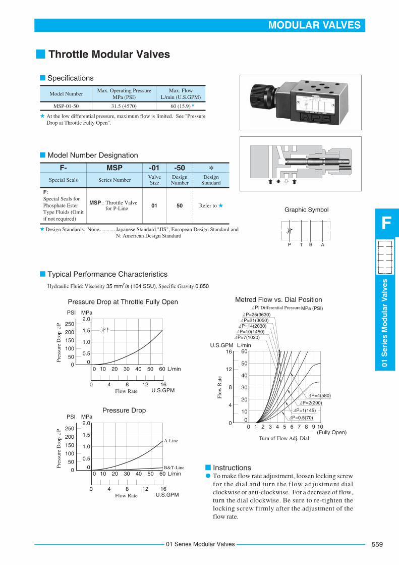
Throttle Modular Valves
L/min
U.S.GPMFlow Rate
MPaPSI
Pressure Drop at Throttle Fully Open
000
0.5
150
200
0 4 8 12 16
1.0
1.5
100
250
10 20 30 40 50 60
2.0
Pre
ssur
e D
rop
P
50
Pressure Drop
L/min
U.S.GPMFlow Rate
0
0 4 8 12 16
10 20 30 40 50 60
MPaPSI
00
0.5
150
200
1.0
1.5
100
2502.0
Pre
ssur
e D
rop
P
50
Flo
w R
ate
U.S.GPM L/min6016
0 1 2 3 4 5 6 7 8 9 10
50
40
30
20
10
0
12
8
4
0
Turn of Flow Adj. Dial
Metred Flow vs. Dial PositionP: Differential Pressure MPa (PSI)
P=7(1020) P=10(1450) P=14(2030) P=21(3050) P=25(3630)
P=4(580)
P=2(290)
P=1(145)
(Fully Open)
Specifications
Model Number
MSP-01-50
Max. Operating Pressure MPa (PSI)
Max. Flow L/min (U.S.GPM)
31.5 (4570) 60 (15.9)
At the low differential pressure, maximum flow is limited. See "Pressure Drop at Throttle Fully Open".
Special Seals for Phosphate Ester Type Fluids (Omit if not required)
F :
MSP : Throttle Valve for P-Line
-50Design Number
Design Standard
Refer to50
F- MSP -01Valve Size
01
Special Seals Series Number
Design Standards: None
Japanese Standard "JIS", European Design Standard andN. American Design Standard
...........
Graphic Symbol
P T B A
Model Number Designation
Typical Performance Characteristics
Instructions
*
Hydraulic Fluid: Viscosity 35 mm2/s (164 SSU), Specific Gravity 0.850
To make flow rate adjustment, loosen locking screw for the dial and turn the flow adjustment dial clockwise or anti-clockwise. For a decrease of flow, turn the dial clockwise. Be sure to re-tighten the locking screw firmly after the adjustment of the flow rate.
B&T-Line
A-Line
P=0.5(70)

DIMENSIONS INMILLIMETRES (INCHES)
5.5(.22) Dia. Through4 Places
Item
SO-BB-P6
SO-NA-P6
SO-NB-P9
SO-NB-P18
Name of Parts Part Numbers Qty.
7
11
12
13
Back Up Ring
O-Ring
O-Ring
O-Ring
1
1
4
1
Remarks
Included in Seal Kit Kit No.: KS-MSP-01-50
P
B A
T
89
12
05
68
97 LOCK
31(1
.22)
47(1
.85)
8(.
31)
1.8
(.07
)
32 D
ia.
(1.2
6)
11(.43)40.5(1.59)
65(2.56)
32.5
(1.2
8)0.
75(.
03)
133 (5.24)Fully Extended
79 (3.11)Fully Extended
40 (
1.57
)
20.5
(.81
)
1.2 kg (2.6 lbs.)Approx. Mass............
Flow Adj. DialINC.
Locking Screw2 (.08) Hex. Soc.
12 1 3 11 7 13 2 5 8 4 10
MSP-01-50
Spare Parts List
MSP-01-50
List of Seals
01 Series Modular Valves560

561
MODULAR VALVES
01S
erie
sM
od
ula
rV
alve
s
F
01 Series Modular Valves
Check and Throttle Modular Valves
InstructionsTo make flow rate adjustment, loosen locking screw for the dial and turn the flow adjustment dial clockwise or anti-clockwise. For a decrease of flow, turn the dial clockwise. Be sure to re-tighten the locking screw firmly after the adjustment of the flow rate.
A-Line
B-Line
T-Line
L/min
U.S.GPMFlow Rate
0
0
Pressure Drop at Throttle Fully OpenMPaPSI
00
0.2
0.4
0.6
0.8
Pre
ssur
e D
rop
P
10 20 30 35
2 4 6 8 9
20
40
60
80
100110
Pressure DropMPaPSI
00Pre
ssur
e D
rop
P
L/min
U.S.GPMFlow Rate
0
0
10 20 30 35
2 4 6 8 9
0.2
0.40.5
20
40
6070
Flo
w R
ate
U.S.GPM L/min35
20
10
00
Turn of Flow Adj. Dial
Metred Flow vs. Dial PositionP: Differential Pressure MPa (PSI)
0 1 2 3 4 5 6 7 8 8.5(Fully Open)
30
2
4
6
8
9
P=21(3050) P=25(3630)
P=14(2030)
P=10(1450)
P=7(1020)
P=4(580)
P=2(290)
P=1(145)
P=0.5(70)
Specifications
Model Number
MSCP-01-30
Max. Operating Pressure MPa (PSI)
Max. Flow L/min (U.S.GPM)
31.5 (4570) 35 (9.25)
At the low differential pressure, maximum flow is limited. See "Pressure Drop at Throttle Fully Open".
Special Seals for Phosphate Ester Type Fluids (Omit if not required)
F :
MSCP :Check and Throttle Valve for P-Line
-30Design Number
Design Standard
Refer to30
F- MSCP -01Valve Size
01
Special Seals Series Number
Design Standards: None
Japanese Standard "JIS", European Design Standard andN. American Design Standard
...........
Graphic Symbol
P T B A
Model Number Designation
Typical Performance Characteristics
Hydraulic Fluid: Viscosity 35 mm2/s (164 SSU), Specific Gravity 0.850
*

DIMENSIONS INMILLIMETRES (INCHES)
5.5(.22) Dia. Through4 Places
Flow Adj. DialINC.
Locking Screw2 (.08) Hex. Soc.
Item
SO-BB-P6
SO-NA-P6
SO-NB-P9
SO-NB-P18
Name of Parts Part Numbers Qty.
11
12
13
14
Back Up Ring
O-Ring
O-Ring
O-Ring
1
1
4
1
Remarks
Included in Seal Kit Kit No.: KS-MSP-01-30
P
B A
T
56
89
78
91
20
LOCK
47(1
.85)
1.8
(.07
)
32 D
ia.
(1.2
6)
11(.43)40.5(1.59)
65(2.56)32
.5(1
.28)
0.75
(.03
)
131.5 (5.18)Fully Extended
77.5 (3.05)Fully Extended
40 (
1.57
)
20.5
(.81
)
1.2 kg (2.6 lbs.)Approx. Mass............
8(.
31)
31(1
.22)
12.5
(.49
)
13 1 5 2 7 3 6 12 11 14 9 10 8 17 16
MSCP-01-30
Spare Parts List
MSCP-01-30
List of Seals
01 Series Modular Valves562

563
MODULAR VALVES
01S
erie
sM
od
ula
rV
alve
s
F
01 Series Modular Valves
Throttle and Check Modular Valves
InstructionsTo make flow rate adjustment, loosen locking screw for the dial and turn the flow adjustment dial clockwise or anti-clockwise. For a decrease of flow, turn the dial clockwise. Be sure to re-tighten the locking screw firmly after the adjustment of the flow rate.
Model Number Designation
P T B A P T B A
P T B A P T B A
P T B A P T B A
P T B A P T B A
Model Numbers
MSA-01-**-50MSB-01-**-50MSW-01-**-50
Max. Operating Pressure MPa (PSI)
Max. Flow L/min (U.S.GPM)
31.5 (4570) 60 (15.9)
-50Design Number
Design Standard
Refer to50
-XDirection of Flow
("A" Line)
Y : Metre-inX : Metre-out
Y
MSA : Throttle and Check Valve for A-Line
MSW -01Valve Size
01
Series Number
Special Seals for Phosphate Ester Type Fluids (Omit if not required)
F :
F-
Special Seals
MSB : Throttle and Check Valve for B-Line
MSW : Throttle and Check Valve for A&B-Lines
Direction of Flow ("B" Line)
Y : Metre-inX : Metre-out
Y : Metre-inX : Metre-out
Y : Metre-inX : Metre-out Y : Metre-in
X : Metre-out
MSA-01-X MSA-01-Y
MSB-01-X MSB-01-Y
MSW-01-X MSW-01-Y
MSW-01-XY MSW-01-YX
Metre-out Metre-in
Metre-out Metre-in Metre-in Metre-out
Graphic Symbols
Specifications
Design Standards: None Japanese Standard "JIS", European Design Standard and N. American Design Standard...........
At the low differential pressure, maximum flow is limited. See "Pressure Drop at Throttle Fully Open" of the next page.
*

Typical Performance CharacteristicsHydraulic Fluid: Viscosity 35 mm2/s (164 SSU), Specific Gravity 0.850
Sol.a
ON
Sol.b
ON
Sol.a
ON
Sol.b
ON
Sol.b
ON
DecompressionEnd Point Pressurisation RetreatAdvance
Centre Position
Clamp Cylinder
Solenoid Operated Directional Valve
Solenoid Operated Directional Valve
1
2
a b
a
b
ABTP
Clamp Cylinder
DSG-01-3C4
MSW-01-XY-50
2
DSG-03-3C121
Pressure DropMPaPSI
0
Pre
ssur
e D
rop
P
L/min
U.S.GPMFlow Rate
0
0.5
1.0
1.5
10 20 30 40 50 60
0 4 8 12 16
2.0
0
50
100
150
200
250
P&T-Line
A-Line: MSB-01 B-Line: MSA-01
Pressure Drop for Free FlowMPaPSI
0
Pre
ssur
e D
rop
P
L/min
U.S.GPMFlow Rate
0
0.5
1.0
1.5
10 20 30 40 50 60
0 4 8 12 16
2.0
0
50
100
150
200
250
MPaPSI
0
Pre
ssur
e D
rop
P
L/min
U.S.GPM
0
0.5
1.0
1.5
10 20 30 40 50 60
0 4 8 12 16
2.0
0
50
100
150
200
250
Flow Rate
Turn of Flow Adj. Dial(Fully Open)0 1 2 3 4 5 6 7 8 9 10
Flo
w R
ate
U.S.GPM L/min
Metred Flow vs. Dial PositionP: Differential Pressure MPa (PSI)
60
50
40
30
20
10
0
16
12
8
4
0
P=21(3050) P=25(3630)
P=14(2030)
P=10(1450)
P=7(1020) P=4(580)
P=2(290) P=1(145)
P=0.5(70)
Pressure Drop at Throttle Fully Open
Circuit of Clamp Cylinder for Injection Molding Machine
Application
Operation Sequence
01 Series Modular Valves564

565
MODULAR VALVES
01S
erie
sM
od
ula
rV
alve
s
F
01 Series Modular Valves
5.5(.22) Dia. Through4 Places
Locking Screw2 (.08) Hex. Soc.
P
A
BT
12
09
8
12
09
8
89
76
5
21
34
5
P
AB
T
12
09
8
P
AB
T
12
09
8
12
09
8
89
76
5LOCK
31(1
.22)
47(1
.85)
8(.
31)
1.8
(.07
)
32 D
ia.
(1.2
6)
11(.43)40.5(1.59)
65(2.56)
210.5 (8.29)Fully Extended83.8 (3.30)
Fully Extended
Flow Adj. Dial (for B-Line)
INC.
0.75
(.03
)
32.5
(1.2
8)
MSW-01-X ------------ 22 (.87) MSW-01-Y ------------ 18 (.71)
40(1
.57)
Flow Adj. Dial (for A-Line) INC.
1.5 kg (3.3 lbs.)Approx. Mass............
40(1
.57)
MSW-01-XY --------- 18 (.71) MSW-01-YX --------- 22 (.87)
MSW-01-XY --------- 22 (.87) MSW-01-YX --------- 18 (.71)
1.5 kg (3.3 lbs.)Approx. Mass............
1.3 kg (2.9 lbs.)Approx. Mass............ 1.3 kg (2.9 lbs.)Approx. Mass............
41.8(1.65)
168.5 (6.63)Fully Extended
83.8 (3.30)Fully Extended
168.5 (6.63)Fully Extended
MSW-01- -50X Y
MSW-01- -50XY YX
XYFor other dimensions, refer to "MSW-01- " drawing above.
MSA-01- -50X Y
For other dimensions, refer to "MSW-01" drawing above.
MSB-01- -50X Y
DIMENSIONS IN MILLIMETRES (INCHES)

Spare Parts List
Note: When ordering seals, please specify the seal kit number from the table right.
Item
SO-BB-P6
SO-NA-P6
SO-NB-P9
SO-NB-P18
Name of Parts Part NumbersMSA,MSB
13
14
15
16
Back Up Ring
O-Ring
O-Ring
O-Ring
1
1
4
2
MSW
2
2
4
2
Quantity
MSA-01
MSB-01
MSW-01
Valve Model Numbers Seal Kit Numbers
KS-MSA-01-30
KS-MSW-01-30
411352131467151
10169
MSA-01- -50X Y
MSB-01- -50X Y
MSW-01-**-50
List of Seals List of Seal Kits
01 Series Modular Valves566

567
MODULAR VALVES
01S
erie
sM
od
ula
rV
alve
s
F
01 Series Modular Valves
Check Modular Valves
Model Numbers
MCP-01-*-30MCT-01-*-30
Max. Operating Pressure MPa (PSI)
Max. Flow L/min (U.S.GPM)
31.5 (4570) 35 (9.25)
Design Standards: None Japanese Standard "JIS", European Design Standard andN. American Design Standard
...........
-30
Design Number
Design Standard
F- MCP -01
Valve SizeSpecial Seals Series Number
-0Cracking Pressure
MPa (PSI)
Special Seals for Phosphate Ester Type Fluids (Omit if not required)
F :
MCP : Check Valve for P-Line
Refer to3001MCT : Check Valve
for T-Line
0 : 0.035 (5)2 : 0.2 (29)4 : 0.4 (58)
Item
SO-NB-P9
SO-NB-P18
Name of Parts Part Numbers Qty.
7
8
O-Ring
O-Ring
4
1
Remarks
Included in Seal Kit Kit No.: KS-MCP-01-30
L/min
U.S.GPMFlow Rate
MPaPSI
Pressure Drop for Free Flow
0
0.6
0
0.8
0 1 2
1.0
1.21.3
Pre
ssur
e D
rop
P
20
5 10 15 20 25 30 35
3 4 5 6 7 8 9
MC*-01-4
MC*-01-2
MC*-01-0
P' (T)
P (T')
0.4
0.2
0
40
60
80
100
120
140
160
180
L/min
U.S.GPM
0
0 1 2
5 10 15 20 25 30 35
3 4 5 6 7 8 9
Pressure Drop
Flow Rate
Pre
ssur
e D
rop
P MPaPSI
0.5700.4
0.2
0
60
40
20
0
T-Line: MCP-01
A-Line
B-Line
P-Line: MCT-01
Graphic Symbols
MCP-01 MCT-01P T B A ABP T
1.1 kg (2.4 lbs.)Approx. Mass......
P
B A
T
5.5(.22) Dia. Through 4 Places
7 1 4 10 5 82
31(1
.22)
47(1
.85)
8(.
31)
1.8
(.07
)11(.43)40.5(1.59)
65(2.56)
32.5
(1.2
8)0.
75(.
03)
36(1.42)
90(3.54)
40(1
.57)
Specifications
Model Number Designation
Typical Performance Characteristics
List of Seals
MCP MCT-01-*-30
MCP MCT-01-*-30
DIMENSIONS IN MILLIMETRES (INCHES)
Hydraulic Fluid: Viscosity 35 mm2/s (164 SSU),Specific Gravity 0.850
*

Anti-Cavitation Modular Valves
Hydraulic Fluid: Viscosity 35 mm2/s (164 SSU),Specific Gravity 0.850
Model Number
MAC-01-30
Max. Operating Pressure MPa (PSI)
Max. Flow L/min (U.S.GPM)
31.5 (4570) 35 (9.25)
Design Standards: None
Japanese Standard "JIS", European Design Standard andN. American Design Standard
...........
-30
Design Number
Design
Standard
F- MAC -01
Valve SizeSpecial Seals Series Number
Special Seals for Phosphate Ester Type Fluids (Omit if not required)
F :
MAC : Anti-Cavitation Valve
Refer to3001
Item
SO-NB-P9
SO-NB-P18
Name of Parts Part Numbers Qty.
7
8
O-Ring
O-Ring
4
2
Remarks
Included in Seal Kit Kit No.: KS-MAC-01-30
A&B-Line
L/min
U.S.GPM
0
Flow Rate
Pressure Drop
5 10 15 20 25 30 35
0 1 2 3 4 5 6 7 8 9
T-Line
P-Line
Pre
ssur
e D
rop
P
MPaPSI0.5
0.4
0.3
0.2
0.1
0
70
60
50
40
30
20
10
0
Graphic Symbol
0.8 kg (1.8 lbs.)Approx. Mass......
T B AP
P
B A
T31
(1.2
2)8
(.31
)
1.8
(.07
)11(.43)40.5(1.59)
65(2.56)
32.5
(1.2
8)0.
75(.
03)
18.5
(.73)80(3.15)
40(1
.57)
47(1
.85)
2 8 5 3 1 4 7
Specifications
Model Number Designation
Presure Drop
List of Seals
MAC-01-30
MAC-01-30
DIMENSIONS IN MILLIMETRES (INCHES)
*
5.5(.22) Dia. Through4 Places
01 Series Modular Valves568

569
MODULAR VALVES
01S
erie
sM
od
ula
rV
alve
s
F
01 Series Modular Valves
Pilot Operated Check Modular Valves
Hydraulic Fluid: Viscosity 35 mm2/s (164 SSU),Specific Gravity 0.850
Japanese Standard "JIS", European Design Standard andN. American Design Standard
Model Numbers
MP*-01-*-40Standard
MP*-01-*-4001Low Pilot Pressure
Control Type
Max. OperatingPressure
MPa (PSI)
Max. Flow L/min (U.S.GPM)
31.5 (4570) 35 (9.25)
Design Standards: None ...........
-40
Design Number
Design Standard
F- MPA -01
Valve SizeSpecial Seals Series Number
-2Cracking Pressure
MPa (PSI)
Special Seals for Phosphate Ester Type Fluids (Omit if not
(Standard)
required)
F :MPA : Pilot Operated
Check Valve for A-Line
Refer to
40
(Low PilotPressureControlType)
400101
2 : 0.2 (29)
4 : 0.4 (58)
MPB : Pilot Operated Check Valve for B-Line
MPW : Pilot Operated Check Valve for A&B-Lines
L/min
U.S.GPMFlow Rate
0 10 20 30 35
0 2 4 6 8 9
MP*-01-4
MP*-01-2
MPaPSIPressure Drop for Free Flow
Pre
ssur
e D
rop
P
0
0.6
0.8
1.0
0.4
0.2
0
20
40
60
80
100
120
140
L/min
U.S.GPMFlow Rate
0 10 20 30 35
0 2 4 6 8 9
Pressure Drop
Pre
ssur
e D
rop
P
MPaPSI0.6
0.4
0.2
0
80
60
40
20
0P,T-Line
A-Line: MPB-01 B-Line: MPA-01
L/min
U.S.GPMFlow Rate
0 10 20 30 35
0 2 4 6 8 9
Pressure Drop for Reversed Controlled FlowMPaPSI
Pre
ssur
e D
rop
P
0.6
0.4
0.2
0
80
60
40
20
0
Min. Pilot Pressure
MPa0
PSISupply Pressure (P2)
0 1000 2000 3000 3500
5 10 15 20 25
Min
. pil
ot P
ress
ure
(PP
) 12MPaPSI
9
6
3
0
17501500
1000
500
0
Graphic Symbols
MPA-01
MPB-01
MPW-01
P T B A
P T B A
P T B A
Specifications
Model Number Designation
Typical Performance Characteristics
*
PP P1
P2 MP *-01-4-40
MP *-01-2-40
MP*-01-4-4001
MP*-01-2-4001

5.5(.22) Dia. Through4 Places
Item
SO-NB-P9
SO-NB-P18
Name of Parts Part Numbers Qty.
11
12
O-Ring
O-Ring
4
2
Remarks
Included in Seal Kit Kit No.: KS-MAC-01-30
P
B A
T
1.2 kg (2.6 lbs.)Approx. Mass............
31(1
.22)
8(.
31)
1.8
(.07
)11(.43)40.5(1.59)
65(2.56)
32.5
(1.2
8)0.
75(.
03)
47(1
.85)
45.5(1.79)
134(5.28)
40(1
.57)
1 4
14
Spare Parts List
List of Seals
DIMENSIONS IN MILLIMETRES (INCHES)
MPA-01-*-40/4001MPB-01-*-40/4001
MPA-01-*-40
MPB-01-*-40
MPW-01-*-40/4001
MPW-01-*-40
1 6 11 7 2 9 12 8 6 7 3 2 9 12
Low Pilot Pressure Control Type(MPW-01-*-4001)
01 Series Modular Valves570

571
MODULAR VALVES
01S
erie
sM
od
ula
rV
alve
s
F
01 Series Modular Valves
End Plates
Hydraulic Fluid: Viscosity 35 mm2/s (164 SSU),Specific Gravity 0.850
Model Numbers
MDC-01-*-30
Max. Operating Pressure MPa (PSI)
Max. Flow L/min (U.S.GPM)
31.5 (4570) 35 (9.25)
Design Standards: None ...........
-30
Design Number
Design Standard
F- MDC -01
Plate SizeSpecial Seals Series Number
-A
Special Seals for Phosphate Ester Type Fluids (Omit if not required)
F :
MDC : End Plate Refer to3001
A : Blocking Plate
B : Bypass Plate
Type of Plate
Pressure Drop
L/min
U.S.GPM
0
Flow Rate
5 10 15 20 25 30 35
0 1 2 3 4 5 6 7 8 9
Pre
ssur
e D
rop
P
MPaPSI0.6
0.4
0.2
0
80
60
40
20
0
P B Line A T Line
Graphic Symbols
1 kg (2.2 lbs.)Approx. Mass.........
P
B A
T
P T B AMDC-01-A
P T B AMDC-01-B
5.5(.22) Dia. Through 9.5(.37) Dia. Spotface
4 Places
31(1
.22)
47(1
.85)
8(.
31)
1.8
(.07
)11(.43)40.5(1.59)
65(2.56)
32.5
(1.2
8)0.
75(.
03)
40(1
.57)
38(1
.50)
O-Ring for Port (SO-NB-P9: 4 Pcs.)
Specifications
Model Number Designation
Typical Performance Characteristics MDC-01-*-30
DIMENSIONS IN MILLIMETRES (INCHES)
Blocking plates are used for auxiliary mounting surface or for closing unnecessary circuits.Bypass plates are used for unidirectional circuits that require no solenoid operated directional valves.
*
Japanese Standard "JIS", European Design Standard andN. American Design Standard
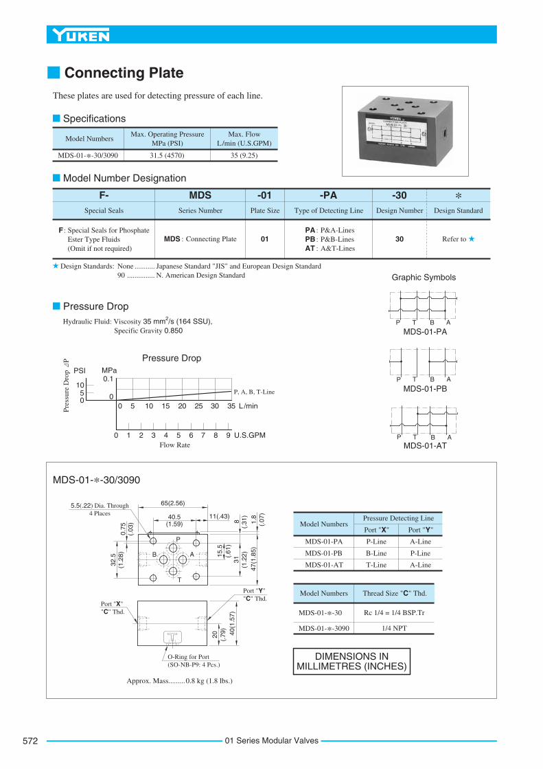
Connecting Plate
Hydraulic Fluid: Viscosity 35 mm2/s (164 SSU),Specific Gravity 0.850
5.5(.22) Dia. Through4 Places
These plates are used for detecting pressure of each line.
Model Numbers
MDS-01-*-30/3090
Max. Operating Pressure MPa (PSI)
Max. Flow L/min (U.S.GPM)
31.5 (4570) 35 (9.25)
Design Standards: None 90
Japanese Standard "JIS" and European Design Standard N. American Design Standard
........... ...............
-30Design Number Design Standard
F- MDS -01Plate SizeSpecial Seals Series Number
-PA
Special Seals for Phosphate Ester Type Fluids (Omit if not required)
F :MDS : Connecting Plate Refer to3001
PA : P&A-Lines
Type of Detecting Line
PB : P&B-LinesAT : A&T-Lines
Model Numbers
MDS-01-PA
MDS-01-PB
MDS-01-AT
P-Line
B-Line
T-Line
A-Line
P-Line
A-Line
Pressure Detecting Line
Port "X" Port "Y"
Model Numbers
MDS-01-*-30
MDS-01-*-3090
Thread Size "C" Thd.
Rc 1/4 = 1/4 BSP.Tr
1/4 NPT
Pressure Drop
L/min
U.S.GPM
0
Flow Rate
5 10 15 20 25 30 35
0 1 2 3 4 5 6 7 8 9
P, A, B, T-Line
Pre
ssur
e D
rop
P
MPaPSI0.1
10
050
Graphic Symbols
P
B A
T
P T B A
MDS-01-PA
P T B A
P T B AMDS-01-AT
MDS-01-PB
31(1
.22)
47(1
.85)
8(.
31)
1.8
(.07
)11(.43)40.5(1.59)
65(2.56)
32.5
(1.2
8)0.
75(.
03)
O-Ring for Port(SO-NB-P9: 4 Pcs.)
0.8 kg (1.8 lbs.)Approx. Mass.........
15.5
(.61
)
Port "Y""C" Thd.
20 (.79
)40
(1.5
7)
Port "X""C" Thd.
Specifications
Model Number Designation
Pressure Drop
MDS-01-*-30/3090
DIMENSIONS IN MILLIMETRES (INCHES)
*
01 Series Modular Valves572

573
MODULAR VALVES
01S
erie
sM
od
ula
rV
alve
s
F
01 Series Modular Valves
Base Plates For Modular Valves
Port Used: Base plate has three (two, in case of 1 station type) pressure port "P"s and four tank port "T"s. Any one of these ports or two or more ports may be used. However, please note that the ports marked with (P) or (T) in the drawing are normally plugged. Remove the plugs when using such ports. Make sure that ports that are not currently used are properly plugged.
When standard base plates (MMC-01) are not used, the mounting surface described on right must be prepared. The mounting surface should have a good machined finish.
Series Number
MMC
MMC : Base Plate 4001
1 : 1 Station
Plate Size
-01Number of Stations
-6
2 : 2 Stations
3 : 3 Stations
4 : 4 Stations
5 : 5 Stations
6 : 6 Stations
7 : 7 Stations
8 : 8 Stations
9 : 9 Stations
10 : 10 Stations
Design Number
-40Design Standard
None : Japanese Standard "JIS"80 : European Design Standard90 : N.American Design Standard
Design Std. "C" Thd. E
Japanese Standard "JIS" and European Design Standard
N.American Design Standard
M5 10 (.39)
No. 10-24 UNC 12 (.47)
P' T' B' A'
B A
PT
PT
L/min
U.S.GPM
0
Flow Rate
10 20 30 35
B'B
PP'
T' T
A' A
0 2 4 6 8 9
Pre
ssur
e D
rop
P
MPaPSI0.3
0.2
0.1
0
40
30
20
10
0
Graphic Symbols
MMC-01-1
MMC-01-2-10
(P)T
P(T)
ABAB
(P)T
P(T)
AB
21.5
(.85
)
12.7
(.50
) 30.2
(1.1
9) 40.5
(1.5
9) 65(2
.56)
11 (.43
)Max. 7(.28) Dia.
4 Places
"C" Thd. "E" Deep4 Places
0.75(.03)
0.75(.03)
32.5(1.28)
50(1.97)
32.5(1.28)
Min. Pitch
5.2(.20)31(1.22)
15.5(.61)
25.8(1.02)
31(1.22) 8(.31)
47(1.85)
SpecificationsMax. Operating Pressure ------------ 25 MPa (3630 PSI)
Model Number Designation
Pressure Drop
Instructions
Interface Mounting Surface Dimensions for 1/8 Modular Valve
DIMENSIONS IN MILLIMETRES (INCHES)
*
Hydraulic Fluid: Viscosity 35 mm2/s (164 SSU),Specific Gravity 0.850
P
B
A
T

DIMENSIONS INMILLIMETRES (INCHES)
"E" Thd. "F" Deep4 Places
Port Holes 6.5(.26) Dia.4 Places
Tank Port (T)"C" Thd.
8.8(.35) Dia. Through14(.55) C'Bore
2 Places
Cylinder Port "A""C" Thd.
Cylinder Port "A""C" Thd.
Each Station
Tank Port "T""C" Thd.
Cylinder Port "B""C" Thd.
Cylinder Port "B""C" Thd.
Each Station
Tank Port (T)"C" Thd.
Pressure Port "P""C" Thd.
MMC-01-*-40/4090
Model Numbers
MMC-01-*-40
MMC-01-*-4090
"C" Thd.
Rc 3/8
3/8 NPT
Thread Size Dimensionsmm (Inches)
"E" Thd. F10
12
M5
No.10-24 UNC
(.39)
(.47)
Model NumbersDimensions mm (Inches)
L1 L2
Approx. Mass kg (lbs.)
"D" Thd.
Rc 1/2
1/2 NPT
Model Numbers
MMC-01-7
MMC-01-8
MMC-01-9
MMC-01-10
Dimensions mm (Inches)
L1 L2
Approx. Mass kg (lbs.)
MMC-01-2
MMC-01-3
MMC-01-4
MMC-01-5
MMC-01-6
137
187
237
287
337
(
(
(
(
(
117
167
217
267
317
4.61)
6.57)
8.54)
10.51)
12.48)
5.5
7.0
8.5
10.0
11.5
5.39)
7.36)
9.33)
11.30)
13.27)
(
(
(
(
(
12.1)
15.4)
18.7)
22.1)
25.4)
(
(
(
(
(
387
437
487
537
(
(
(
(
367
417
467
517
14.45)
16.42)
18.39)
20.35)
13.0
14.5
16.0
17.5
15.24)
17.20)
19.17)
21.14)
(
(
(
(
28.7)
32.0)
35.3)
38.6)
(
(
(
(
Pressure Port (P)"C" Thd.
Pressure Port "P""C" Thd.
(P)
T
P(T)
BT
A
P
L
28
32.5
12.5
40.5
72(2
.83)
10
5028
P(T)
B
TA
P
1
L 2
Approx. Mass : 3.5 kg (7.7 lbs.)
(1.28)
(.49
)(1
.59)
(1.10)
36(1
.42)
53(2.09)
18(.71) 27(1.06)
53(2.09)
18(.71)
72(2
.83)
62(2
.44)
54(2
.13)
21(.
83)
21(.
83)
21(.
83)36
(1.4
2)
72(2
.83)
36(1
.42)
(.39)Threaded Holes 4 Places
Port Holes 4 Places
Pitch
(1.97)(1.10) 53(2.09)
18(.71)
21(.
83)
21(.
83)
36(1
.42)
72(2
.83)
62(2
.44)
54(2
.13)
18(.
71)
B
A
43(1
.69)
8.8(.35) Dia. Through14(.55) C'Bore
2 Places
46(1
.81)
87(3.43)
67(2.64) 10(.39)
0.75(.03)
31(1.22)
62(2.44)
36(1
.42)
18(.
71)
B
A
45(1.77)
32.5(1.28)
BT
A
PB
T
A
PB
T
A
PB
T
AP
Each Station
12.5
(.49
)40
.5(1
.59)
31(1.22)
50Pitch
(1.97)42
(1.65)
B
A
B
A
B
A
B
A
(T)
(P)
46(1.81)
27(1.06)
62(2.44)
69(2.72)
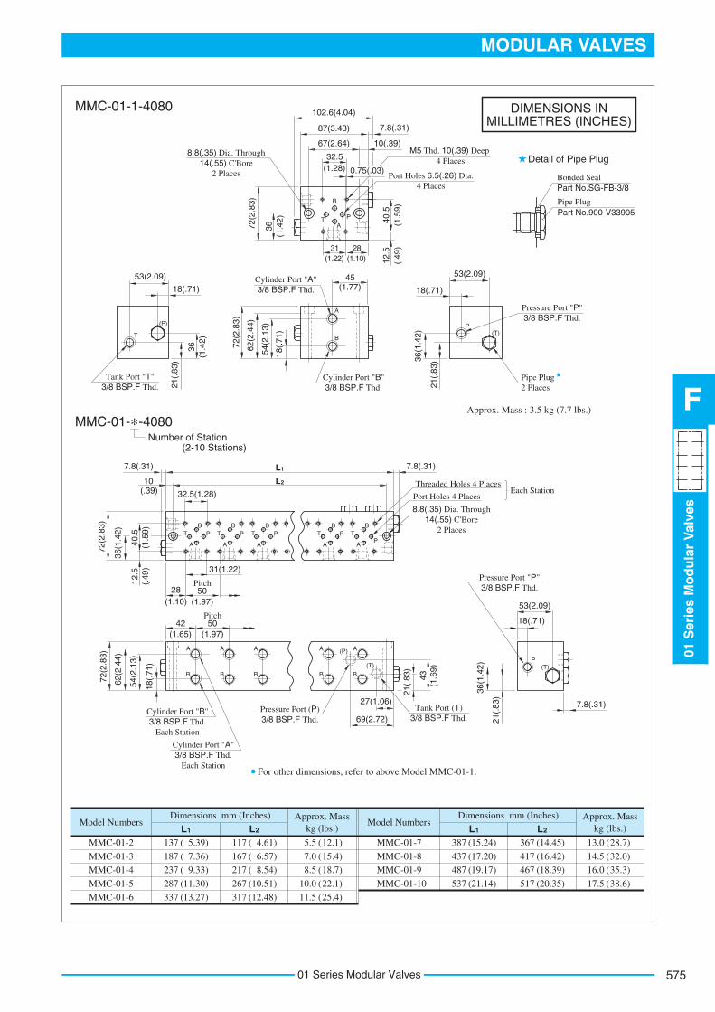
For other dimensions, refer to above Model MMC-01-1.
MMC-01-1-40/4090
Number of Station(2-10 Stations)
The two tank ports (T) are not machinedfor 4090 design.
Tank Port (T)"D" Thd.
Tank Port (T)"C" Thd.
01 Series Modular Valves574
575
MODULAR VALVES
01S
erie
sM
od
ula
rV
alve
s
F
01 Series Modular Valves
DIMENSIONS INMILLIMETRES (INCHES)
MMC-01-*-4080
Port Holes 6.5(.26) Dia.4 Places
8.8(.35) Dia. Through14(.55) C'Bore
2 Places
8.8(.35) Dia. Through14(.55) C'Bore
2 Places
Model NumbersDimensions mm (Inches)
L1 L2
Approx. Mass kg (lbs.)
Model Numbers
MMC-01-7
MMC-01-8
MMC-01-9
MMC-01-10
Dimensions mm (Inches)
L1 L2
Approx. Mass kg (lbs.)
MMC-01-2
MMC-01-3
MMC-01-4
MMC-01-5
MMC-01-6
137
187
237
287
337
(
(
(
(
(
117
167
217
267
317
4.61)
6.57)
8.54)
10.51)
12.48)
5.5
7.0
8.5
10.0
11.5
5.39)
7.36)
9.33)
11.30)
13.27)
(
(
(
(
(
12.1)
15.4)
18.7)
22.1)
25.4)
(
(
(
(
(
387
437
487
537
(
(
(
(
367
417
467
517
14.45)
16.42)
18.39)
20.35)
13.0
14.5
16.0
17.5
15.24)
17.20)
19.17)
21.14)
(
(
(
(
28.7)
32.0)
35.3)
38.6)
(
(
(
(
Bonded Seal Part No.SG-FB-3/8
Pipe Plug Part No.900-V33905
Cylinder Port "A"3/8 BSP.F Thd.
Cylinder Port "A"3/8 BSP.F Thd.
Each Station
Cylinder Port "B"3/8 BSP.F Thd.
Cylinder Port "B"3/8 BSP.F Thd.
Each Station
Pressure Port "P"3/8 BSP.F Thd.
Pressure Port (P)3/8 BSP.F Thd.
Pressure Port "P"3/8 BSP.F Thd.
Tank Port "T"3/8 BSP.F Thd.
Tank Port (T)3/8 BSP.F Thd.
Pipe Plug2 Places
M5 Thd. 10(.39) Deep 4 Places
(P)
T
P(T)
BT
A
P
L
28
32.5
12.5
40.5
72(2
.83)
10
5028
P(T)
B
TA
P
1
L 2
Approx. Mass : 3.5 kg (7.7 lbs.)
(1.28)
(.49
)(1
.59)
(1.10)36
(1.4
2)53(2.09)
18(.71)
53(2.09)
18(.71)
72(2
.83)
54(2
.13)
21(.
83)
21(.
83)36
(1.4
2)
72(2
.83)
36(1
.42)
(.39)
Pitch
(1.97)(1.10) 53(2.09)
18(.71)
21(.
83)
21(.
83)
36(1
.42)
72(2
.83)
62(2
.44)
54(2
.13)
18(.
71)
B
A
43(1
.69)
87(3.43)
67(2.64) 10(.39)
0.75(.03)
31(1.22)
36(1
.42)
18(.
71)
B
A
45(1.77)
32.5(1.28)
BT
A
PB
T
A
PB
T
A
PB
T
AP
12.5
(.49
)40
.5(1
.59)
31(1.22)
50Pitch
(1.97)42
(1.65)
B
A
B
A
B
A
B
A
(T)
(P)
27(1.06)
69(2.72)
For other dimensions, refer to above Model MMC-01-1.
102.6(4.04)
7.8(.31)
7.8(.31)7.8(.31)
7.8(.31)
62(2
.44)
MMC-01-1-4080
Number of Station(2-10 Stations)
Detail of Pipe Plug
Threaded Holes 4 Places
Port Holes 4 PlacesEach Station

Mounting Bolt KitsValves are mounted with four stud bolts. Valve combination varies according to the circuit type. Hence, the mounting bolt kits are available on a combination type basis.When ordering the bolt kit, be sure to give the bolt kit model number from the table below.
Stacking Example
Design Standards: None 90
........... ...............
-30Design Number
Design Standard
MBK -01Size of
Modular ValveSeries Number
-02
MBK : Bolt Kits for Modular Valves
Refer to3001
Bolt Number
Model Numbers
MBK-01-01-30
MBK-01-02-30
MBK-01-03-30
MBK-01-04-30
MBK-01-01-3090
MBK-01-02-3090
MBK-01-03-3090
MBK-01-04-3090
01, 02, 03, 04, 05 (Refer to the
following chart)
Japanese Standard "JIS" and European Design Standard N. American Design Standard
Operating Pressure MPa (PSI)
25(3630) or less
More Than 25(3630)
Tightening Torque Nm (in. lbs.)
Model Numbers
Solenoid Operated
Directional Valve
(*-DSG-01)
End Plate (MDC-01)
Modular Valve &
Connecting Plate
Approx. Mass
g (lbs.)
Quantity of valves to be stacked
MBK-01-01-30*
MBK-01-02-30*
MBK-01-03-30*
MBK-01-04-30*
MBK-01-05-30*
1
0
1
0
1
0
1
0
1
0
0
1
0
1
0
1
0
1
0
1
1
2
3
4
0
60(.13)
100(.22)
130(.29)
160(.35)
40(.09)
(
(
(
(
(
(
(
(
94
134
174
214
94
134
174
214
)
)
)
)
)
)
)
)
3.70
5.28
6.85
8.43
3.70
5.28
6.85
8.43
A mm (In.) "B" Thd.
M5
No.10-24 UNC
"B" Thd.Both Ends
8.5
Dia
.(.
33)
9(.35)
A
5 - 6 (44 - 53)
6 - 7 (53 - 62)
9(.35)
"B" Thd.
9(.35)
15(.59)
4(.16)
MBK-01-05-30: M5 45 Lg. MBK-01-05-3090: No.10-24 UNC 1-3/4 Lg.
MBK-01-05-30: 4(.16)MBK-01-05-3090: 3.97(5/32)
Nut
Stud BoltMounting Bolt Kit
Solenoid OperatedDirectional Valve
01 SeriesModularValves
Base Plate
Model Number Designation
MBK-01-01/02/03/04-30/3090
Bolt Kit Composition
Note:
1 Set
Tightening Torque:
Stud Bolt ------ 4 Pcs. Nut ------------- 4 Pcs.
Bolt Kits Selection Chart
MBK-01-05-30/3090
Stud Bolt
Nut
Socket Head Cap Screw
DIMENSIONS IN MILLIMETRES (INCHES)
*In case of bolt kit model number having "05", four hexagon socket head cap screws only.
SOL a SOL b
1.
2.
In case of MBK-01-04-30*, operating pressure is restricted at 25 MPa(3630 PSI) or less.The solenoid operated directional valve comes with mounting bolts.
2
1
01 Series Modular Valves576