Embed Size (px)
Citation preview
GE Energy Connections Grid Solutions
Type MHOR 04
User Manual High Speed Pilot Wire Feeder Protection
Publication reference: R8042K

Service Manual type MHOR 04
High Speed Pilot Wire Feeder Protection
HANDLING OF ELECTRONIC EQUIPMENT
A person's normal movements can easily generate electrostatic potentials of several thousand volts. Discharge of these voltages into semiconductor devices when handling electronic circuits can cause serious damage, which often may not be immediately apparent but the reliability of the circuit will have been reduced.
The electronic circuits of General Electric products are completely safe from electrostatic discharge when housed in the case. Do not expose them to the risk of damage by withdrawing modules unnecessarily.
Each module incorporates the highest practicable protection for its semiconductor devices. However, if it becomes necessary to withdraw a module, the following precautions should be taken to preserve the high reliability and long life for which the equipment has been designed and manufactured.
1. Before removing a module, ensure that you are at the same electrostatic potential as theequipment by touching the case.
2. Handle the module by its front-plate, frame, or edges of the printed circuit board. Avoidtouching the electronic components, printed circuit track or connectors.
3. Do not pass the module to any person without first ensuring that you are both at the sameelectrostatic potential. Shaking hands achieves equipotential.
4. Place the module on an antistatic surface, or on a conducting surface which is at thesame potential as yourself.
5. Store or transport the module in a conductive bag.
More information on safe working procedures for all electronic equipment can be found in BS5783 and IEC 60147-0f.
If you are making measurements on the internal electronic circuitry of an equipment in service, it is preferable that you are earthed to the case with a conductive wrist strap. Wrist straps should have a resistance to ground between 500k – 10m ohms. If a wrist strap is not available, you should maintain regular contact with the case to prevent the build up of static. Instrumentation which may be used for making measurements should be earthed to the case whenever possible.
General Electric strongly recommends that detailed investigations on the electronic circuitry, or modification work, should be carried out in a special handling area such as described in BS5783 or IEC 60147-0f.

4
CONTENTS
SAFETY SECTION 5
1. DESCRIPTION 9
2. INSTALLATION 9 2.1 General 9 2.2 Relay mounting 9 2.3 Unpacking 10 2.4 Storage 10 2.5 Site 10
3. COMMISSIONING 10 3.1 Commissioning preliminaries 10 3.1.1 Inspection 10 3.1.2 Wiring 11 3.1.3 Earthing 11 3.1.4 Insulation 11 3.1.5 Suggested test equipment 11 3.2 Electrical tests 12 3.2.1 Tests on pilot wires 12 3.2.2 Secondary injection tests 13 3.2.3 Primary injection tests 14 3.2.4 On load tests 14 3.3 MHOR 04/SOLKOR R Schemes 16 3.3.1 Onload tests 16
4. SETTINGS 18 4.1 Pilot padding resistors 18 4.2 Neutral tap N 18
5. MAINTENANCE 18
6. PROBLEM ANALYSIS 18 6.1 Removal of the relay from its case 19 6.2 Pilot padding resistor Rpp 19 6.3 CAG element 19 6.4 Spares 19
REPAIRS 19
7. COMMISSIONING TEST RECORD 25
REPAIR FORM 27

SAFETY SECTION
This Safety Section should be read before commencing any work on the equipment.
Health and safety
The information in the Safety Section of the product documentation is intended to ensure that products are properly installed and handled in order to maintain them in a safe condition. It is assumed that everyone who will be associated with the equipment will be familiar with the contents of the Safety Section.
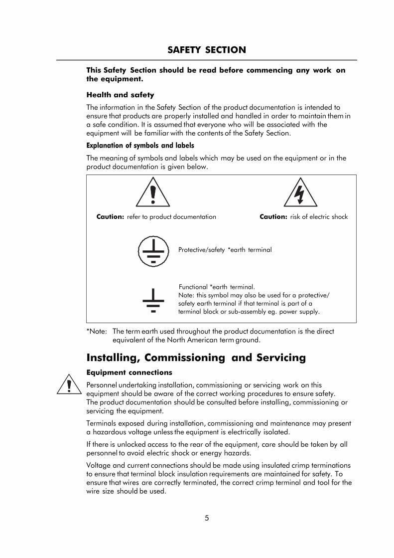
Explanation of symbols and labels
The meaning of symbols and labels which may be used on the equipment or in the product documentation is given below.
Caution: refer to product documentation Caution: risk of electric shock
Protective/safety *earth terminal
Functional *earth terminal. Note: this symbol may also be used for a protective/ safety earth terminal if that terminal is part of a terminal block or sub-assembly eg. power supply.
*Note: The term earth used throughout the product documentation is the direct equivalent of the North American term ground.
Installing, Commissioning and Servicing
Equipment connections
Personnel undertaking installation, commissioning or servicing work on this equipment should be aware of the correct working procedures to ensure safety. The product documentation should be consulted before installing, commissioning or servicing the equipment.
Terminals exposed during installation, commissioning and maintenance may present a hazardous voltage unless the equipment is electrically isolated.
If there is unlocked access to the rear of the equipment, care should be taken by all personnel to avoid electric shock or energy hazards.
Voltage and current connections should be made using insulated crimp terminations to ensure that terminal block insulation requirements are maintained for safety. To ensure that wires are correctly terminated, the correct crimp terminal and tool for the wire size should be used.
5
6
Before energising the equipment it must be earthed using the protective earth terminal, or the appropriate termination of the supply plug in the case of plug connected equipment. Omitting or disconnecting the equipment earth may cause a safety hazard.
The recommended minimum earth wire size is 2.5 mm2, unless otherwise stated in the technical data section of the product documentation.
Before energising the equipment, the following should be checked:
Voltage rating and polarity;
CT circuit rating and integrity of connections;
Protective fuse rating;
Integrity of earth connection (where applicable)
Equipment operating conditions
The equipment should be operated within the specified electrical and environmental limits.
Current transformer circuits
Do not open the secondary circuit of a live CT since the high voltage produced may be lethal to personnel and could damage insulation.
External resistors
Where external resistors are fitted to relays, these may present a risk of electric shock or burns, if touched.
Battery replacement
Where internal batteries are fitted they should be replaced with the recommended type and be installed with the correct polarity, to avoid possible damage to the equipment.
Insulation and dielectric strength testing
Insulation testing may leave capacitors charged up to a hazardous voltage. At the end of each part of the test, the voltage should be gradually reduced to zero, to discharge capacitors, before the test leads are disconnected.
Insertion of modules and pcb cards
These must not be inserted into or withdrawn from equipment whilst it is energised, since this may result in damage.
Fibre optic communication
Where fibre optic communication devices are fitted, these should not be viewed directly. Optical power meters should be used to determine the operation or signal level of the device.
Older Products
Electrical adjustments
Equipments which require direct physical adjustments to their operating mechanism to change current or voltage settings, should have the electrical power removed before making the change, to avoid any risk of electric shock.
Mechanical adjustments
The electrical power to the relay contacts should be removed before checking any mechanical settings, to avoid any risk of electric shock.
Draw out case relays
Removal of the cover on equipment incorporating electromechanical operating elements, may expose hazardous live parts such as relay contacts.
Insertion and withdrawal of extender cards
When using an extender card, this should not be inserted or withdrawn from the equipment whilst it is energised. This is to avoid possible shock or damage hazards. Hazardous live voltages may be accessible on the extender card.
Insertion and withdrawal of heavy current test plugs
When using a heavy current test plug, CT shorting links must be in place before insertion or removal, to avoid potentially lethal voltages.
Decommissioning and Disposal
Decommissioning: The auxiliary supply circuit in the relay may include capacitors across the supply or to earth. To avoid electric shock or energy hazards, after completely isolating the supplies to the relay (both poles of any dc supply), the capacitors should be safely discharged via the external terminals prior to decommissioning.
Disposal: It is recommended that incineration and disposal to water courses is avoided. The product should be disposed of in a safe manner. Any products containing batteries should have them removed before disposal, taking precautions to avoid short circuits. Particular regulations within the country of operation, may apply to the disposal of lithium batteries.
7
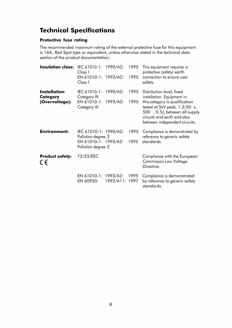
Technical Specifications
Protective fuse rating
The recommended maximum rating of the external protective fuse for this equipment is 16A, Red Spot type or equivalent, unless otherwise stated in the technical data section of the product documentation.
Insulation class: IEC 61010-1: Class I EN 61010-1:
1990/A2: 1993/A2:
1995 1995
This equipment requires a protective (safety) earth connection to ensure user
Class I safety.
Installation Category (Overvoltage):
IEC 61010-1: Category III EN 61010-1:
1990/A2: 1993/A2:
1995 1995
Distribution level, fixed installation. Equipment in this category is qualification
Category III tested at 5kV peak, 1.2/50 s, 500 , 0.5J, between all supply circuits and earth and also between independent circuits.
Environment: IEC 61010-1: 1990/A2: 1995 Compliance is demonstrated by Pollution degree 2 reference to generic safety EN 61010-1: 1993/A2: 1995 standards. Pollution degree 2
Product safety: 73/23/EEC Compliance with the European
Commission Low Voltage Directive.
EN 61010-1: 1993/A2: 1995 Compliance is demonstrated EN 60950: 1992/A11: 1997 by reference to generic safety
standards.
8
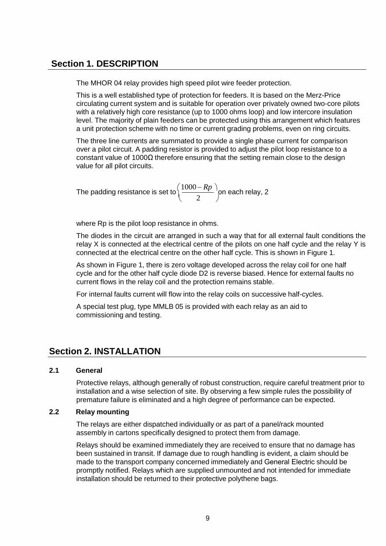
Section 1. DESCRIPTION
The MHOR 04 relay provides high speed pilot wire feeder protection.
This is a well established type of protection for feeders. It is based on the Merz-Price circulating current system and is suitable for operation over privately owned two-core pilots with a relatively high core resistance (up to 1000 ohms loop) and low intercore insulation level. The majority of plain feeders can be protected using this arrangement which features a unit protection scheme with no time or current grading problems, even on ring circuits.
The three line currents are summated to provide a single phase current for comparison over a pilot circuit. A padding resistor is provided to adjust the pilot loop resistance to a constant value of 1000Ω therefore ensuring that the setting remain close to the design value for all pilot circuits.
The padding resistance is set to 1000 − Rp on each relay, 2 2
where Rp is the pilot loop resistance in ohms.
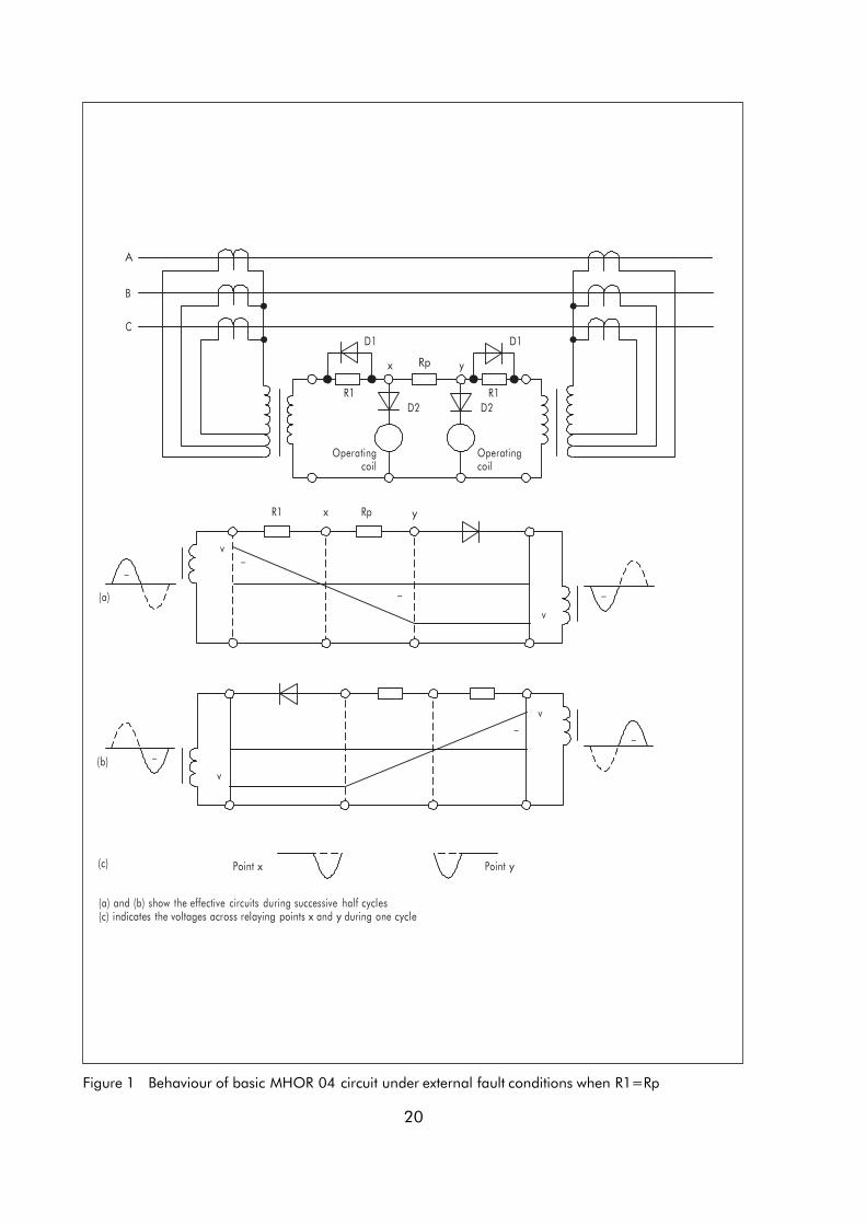
The diodes in the circuit are arranged in such a way that for all external fault conditions the relay X is connected at the electrical centre of the pilots on one half cycle and the relay Y is connected at the electrical centre on the other half cycle. This is shown in Figure 1.
As shown in Figure 1, there is zero voltage developed across the relay coil for one half cycle and for the other half cycle diode D2 is reverse biased. Hence for external faults no current flows in the relay coil and the protection remains stable.
For internal faults current will flow into the relay coils on successive half-cycles.
A special test plug, type MMLB 05 is provided with each relay as an aid to commissioning and testing.
Section 2. INSTALLATION
2.1
2.2
General Protective relays, although generally of robust construction, require careful treatment prior to installation and a wise selection of site. By observing a few simple rules the possibility of premature failure is eliminated and a high degree of performance can be expected.
Relay mounting
The relays are either dispatched individually or as part of a panel/rack mounted assembly in cartons specifically designed to protect them from damage.
Relays should be examined immediately they are received to ensure that no damage has been sustained in transit. If damage due to rough handling is evident, a claim should be made to the transport company concerned immediately and General Electric should be promptly notified. Relays which are supplied unmounted and not intended for immediate installation should be returned to their protective polythene bags.
9
2.3 Unpacking
Care must be taken when unpacking and installing the relays so that none of the parts are damaged or their settings altered and must only be handled by skilled persons.
Relays should be examined for any wedges, clamps, or rubber bands necessary to secure moving parts to prevent damage during transit and these should be removed after installation and before commissioning.
Relays which have been removed from their cases should not be left in situations where they are exposed to dust or damp. This particularly applies to installations which are being carried out at the same time as construction work.
2.4 Storage
If relays are not installed immediately upon receipt they should be stored in a place free from dust and moisture in their original cartons and where de-humidifier bags have been included in the packing they should be retained. The action of the de- humidifier crystals will be impaired if the bag has been exposed to ambient conditions and may be restored by gently heating the bag for about an hour, prior to replacing it in the carton.
Dust which collects on a carton may, on subsequent unpacking, find its way into the relay; in damp conditions the carton and packing may become impregnated with moisture and the de-humidifying agent will lose its efficiency.
The storage temperature range is –25 C to +70 C.
2.5 Site
The installation should be clean, dry and reasonably free from dust and excessive vibration. The site should preferably be well illuminated to facilitate inspection.
An outline diagram is normally supplied showing panel cut-outs and hole centres. For individually mounted relays these dimensions will also be found in Publication R6042.
Publication R7012, Parts Catalogue and Assembly Instructions, will be useful when individual relays are to be assembled as a composite rack or panel mounted assembly.
Publication R6001 is a leaflet on the modular integrated drawout system of protective relay.
Publication R6014 is a list of recommended suppliers for the pre-insulated connectors.
Section 3. COMMISSIONING
3.1 Commissioning preliminaries
3.1.1 Inspection
Carefully examine the module and case to see that no damage has occurred during transit. Check that the relay serial number on the module, case and cover are identical, and that the model number and rating information are correct.
Carefully remove any elastic bands/packing fitted for transportation purposes.
Carefully actuate the armature of the output element with a small screwdriver/probe.
10

Note that immediately after the point where any normally open contacts just make, there is a small further movement of the armature. This ensures that contact follow through and wiping action is present. Repeat similarly with normally closed contacts on armature release.
Check that the flag is free to fall before or just as any normally open contacts touch.
3.1.2 Wiring
Check that the external wiring is correct to the relevant relay diagram or scheme diagram. The relay diagram number appears inside the case.
Particular attention should be paid to the correct wiring and value of any external resistors indicated on the wiring diagram/relay rating information.
Note that shorting switches shown on the relay diagram are fitted internally across the relevant case terminals and close when the module is withdrawn. It is essential that such switches are fitted across all CT circuits.
If test block type MMLG is provided, the connections should be checked to the scheme diagram, particularly that the supply connections are to the ‘live’ side of the test block (coloured orange) and with terminals allocated with odd numbers (1, 3, 5, 7, etc.). The auxiliary supply voltage to the scheme, if relevant, should be routed via test block terminals 13 and 15.
3.1.3 Earthing
Ensure that the case earthing connection above the rear terminal block is used to connect the relay to a local earth bar.
3.1.4 Insulation
The relay and its associated wiring may be insulation tested between:
– all electrically isolated circuits – all circuits and earth
An electronic or brushless insulation tester should be used, having a dc voltage not exceeding 1000V. Accessible terminals of the same circuit should first be strapped together. Deliberate circuit earthing links, removed for the tests, subsequently must be replaced.
3.1.5 Suggested test equipment
Insulation tests:
500V dc insulation resistance tester
Secondary injection tests:
2 test plugs Use 4mm shrouded plugs (not supplied)
2 test plugs type MMLB 01 If MMLG test block is fitted 1 single finger test plug type MMLB 02
Overcurrent test set type CFB or CFBA
or alternatively a current supply capable of 4 x rated current (1A or 5A) and having a source impedance of greater than 50 or greater than 2 for a 1A or 5A relay respectively.
Two multipurpose instruments (Avometers, etc.)
Ohmmeter, if not included above
11
Additional equipment for primary injection tests
Primary injection current test set, capable of 50% of CT primary rating and typically 3-5kVA output. An ammeter/measuring CT for measurements of up to 50% CT primary rating.
3.2 Electrical tests
When conducting tests given in this section, please note:
DANGER
DO NOT OPEN CIRCUIT THE SECONDARY CIRCUIT OF A CURRENT TRANSFORMER SINCE THE HIGH VOLTAGE PRODUCED MAY BE LETHAL AND COULD DAMAGE INSULATION.
When type MMLG test block facilities are installed, it is important that the sockets in the type MMLB01 test plug, which correspond to the current transformer secondary windings, are LINKED BEFORE THE TEST PLUG IS INSERTED INTO THE TEST BLOCK. Similarly, a MMLB 02 single finger test plug must be terminated with an ammeter BEFORE IT IS INSERTED to monitor CT secondary currents.
Secondary injection test methods are included below since they provide a ready reference for simplified future maintenance tests. They do not however, prove true primary sensitivities unless CT ratios and losses are known. Secondary injection, primary injection and on-load tests are included below in this order, although CT ratios and relative winding polarities for each group of CTs may, if desired, be proven first.
3.2.1 Tests on pilot wires
It should be noted that at all times pilot cables should be treated as potentially of high voltage. Standard safety precautions and regulations for working on such cables should be observed when conducting the following tests. Pilot connections for these tests can be made to terminals 17 and 18 at the rear of the case, as indicated in Figure 2, with the relays at both ends removed from their cases, and insulated cards inserted between the shorting contacts in each case. Do not insert insulated cards on any other terminals other than 17 and 18.
3.2.1.1 Insulation resistance tests
With the pilots isolated from the relay circuits at both ends of the feeder measure the insulation resistance between both pilot wires and between each pilot wire and earth. Measurements will depend on pilot length and type, but a figure in excess of 1M at 500V would normally be accepted as satisfactory. Lower insulation results should be compared with insulation data for the type of cable used.
3.2.1.2 Pilot loop resistance
Short the remote end of the pilot wires together by removing the insulated card from the remote relay case and measure the pilot loop resistance with an ohmmeter. Note the reading for future reference.
3.2.1.3 Identification of pilots for relay connections
It is essential for correct relay operation that each pilot is connected to the same terminal number on both local and remote relay.
With isolated pilots, short the remote end of one pilot to earth. At the local end measure the resistance of each pilot to earth. The pilot wire giving the lower of the two readings corresponds to that earthed at the remote end. Connect the pilots to the relays as indicated in Figure 2.
12
3.2.2 Secondary injection tests
It is essential that the pilot wires are connected correctly and the remote end relay is de-energised, as would be the case with an isolated feeder.
If, during maintenance tests, it is impracticable to de-energise the line, secondary injection testing can only be carried out provided the secondaries of both groups of line end CTs are terminated, and the relay summation transformer input of the remote end relay left open-circuit. MMLG test block (if fitted) and MMLB 01 test plug simplify these circuit changes.
However, before this is done, MHOR04 tripping circuits at both ends must be isolated to prevent maloperation of the circuit breakers. Back-up protection systems must be relied on during on-load testing.
The following tests assume initial commissioning tests are being carried out on a de-energised feeder.
3.2.2.1 Adjustment of pilot-padding resistance
The pilot padding resistance of both line-end relays must first be set to ohmic value given below.
Pilot padding resistance = 1000 – pilot loop resistance
2
ohms
The padding resistance is adjusted at the front of the relay by a potentiometer-type control that is calibrated directly in ohms.
3.2.2.2 Check on open-circuit pilot sensitivity
Temporarily open circuit the pilots and, with N = 3 on plugbridge on frontplate of relay, inject A-N current (terminals 23-24). Slowly increase the level until the output relay operates. Note the pick-up current level which should be 0.13A (1A relay) or 0.65A (5A relay), with a tolerance of 10%.
Remove the open circuit from the pilots.
3.2.2.3 Electrical check on correct pilot polarity
With A-N current injection as in 3.2.2.2 above, but with pilots connected, connect an ac milliammeter in the pilot circuit to monitor the pilot current. Increase the current until the local relay just operates noting both the injected level and pilot currents: these should be nominally 0.235A (1.18A, 5A relay) and 8.2mA respectively, but will increase with high capacitance pilots.
Temporarily reverse the pilot connections and increase the injected A-N current, repeating the above. The pick up current should be typically 90-95% of the previous reading, but the pilot current should be higher and in the order of 10mA. These results confirm that the correct pilot polarities had been selected. Return the pilot connections to normal.
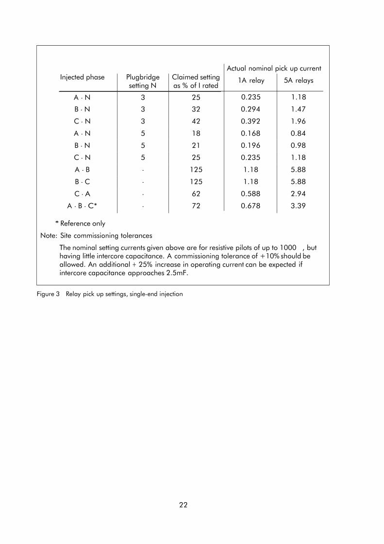
3.2.2.4 Record of pick-up settings
Note the desired CT neutral tap setting (N = 3 or 5). A table of nominal pick up currents for each phase to phase and phase to neutral connection is given in Figure 3, together with a guide to expected tolerances.
Inject A to neutral (N=3 or 5) current and note the local end pick up level.
13
With communications to the remote end, gradually increase the level until the remote end relay operates. This should occur at 1.2-2.4 x the nominal local end pick up level.
Repeat, recording the local end PU current only, for B to neutral, C to neutral, A – B, B – C and C – A injection.
3.2.2.5 Secondary injection tests on untested ‘remote’ end
Section 3.2.2.2 and 3.2.2.4 should be repeated for the ‘remote’ end relay.
3.2.3 Primary injection tests
DANGER
WHEN CONDUCTING TESTS IN THIS SECTION THE SECONDARY WINDINGS OF THE CURRENT TRANSFORMERS MUST NOT BE ALLOWED TO GO OPEN CIRCUIT. ATTENTION SHOULD BE PAID TO THE DANGER WARNING AT THE START OF SECTION 3.2.
3.2.3.1 Individual CT ratio and wiring check
Connect ammeters in series with case terminal 23 and the CT neutral and apply a known level of current (say 50-100% of CT rating) through the A phase CT primary and measure the secondary currents A1 and A2. Both should be equal and approximate the primary I x CT ratio. Repeat for the B and C phase CTs, measuring in terminals 25 and 27 respectively.
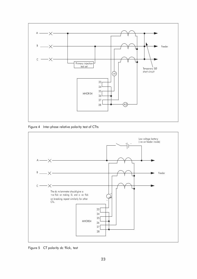
3.2.3.2 Inter-phase relative polarity test of CTs
Connect ammeters in series with terminal 25 and the CT neutral as in Figure 4. With the A2 ammeter initially on a high range (2 x the expected CT secondary current) energise the A and B phase CTs as indicated, with 50-100% CT rated current. The A1 ammeter reading should approximate the primary current x the CT rating, but the A2 ammeter should only record a few milliamperes of spill current. This test proves that both CTs are of the same polarity. Repeat as indicated in Figure 4 for the B-C phases, still measuring currents in 25 and the CT neutral.
Note: If 2 x the reading of the A1 ammeter is obtained on A2, one of the two CTs being tested is of reversed polarity. CT wiring should be carefully checked. Ideally a CT polarity dc ‘flick’ test should be carried out, as indicated in Figure 5, which will prove the definite polarity of each CT.
3.2.3.3 Primary pick up sensitivity
Connect the primary injection test set across the A phase CT primary. Monitor the CT secondary current into relay terminal 23. Increase the injected current until the local relay operates, and record both primary and secondary pick up levels.
Similarly, repeat the above for the B and C phase CTs monitoring the secondary current to the relay at terminal 25 and 27 respectively, ensuring the other CTs are correctly terminated by the relay.
3.2.4 On load tests
DANGER
WHEN CONDUCTING TESTS IN THIS SECTION, THE SECONDARY WINDINGS OF THE CURRENT TRANSFORMERS MUST NOT BE ALLOWED TO GO OPEN CIRCUIT. ATTENTION SHOULD BE PAID TO THE DANGER WARNING AT THE START OF SECTION 3.2.
14
The following tests should be carried out preferably with at least 50% load current flowing in the feeder and the relay trip circuits at both ends isolated.
3.2.4.1 Check on load current
If MMLG/MMLB test facilities (or equivalent) are available, measure the CT secondary load current to ensure that it is above a suggested absolute minimum 20%.
3.2.4.2 Stability test
Short circuit B and C phase CT secondaries and isolate them from the relays at both ends. This simulates an A-N through fault condition and the most sensitive phase condition for the relays. When these conditions are applied both relays should be in the stable, unoperated condition.
Measure the circulating pilot current in terminal 17. This should be approximately 44 or 66mA ac for the 50% or 100% load condition respectively and N = 3 setting, or approximately 40% higher if the N = 5 setting is used.
Similarly, measure the dc current to the CAG relay element using the special test plug in the socket on the relay frontplate. The current should be nominally zero, but certainly less than 1.5mA.
Repeat the above tests for B-N, monitoring pilot current and the dc current in the CAG coil. These currents should be less than those measured for the A-N condition because of the relays lower sensitivity to this type of fault.
Repeat again for C-N, noting the still lower values of current.
Note: If relays operate, or tend to operate, with the above tests, it indicates that the polarity and/or phasing of the CTs are suspect, or that the polarity of the pilots is incorrect. Reference should be made to section 3.2.2.3 for pilot wire polarity tests. On no account should they be changed from that determined to be correct in section 3.2.2.3. If the CT polarities are incorrect, they must be corrected at the CTs. Reversing the pilots, as can normally be done on most pilot wire schemes, may indicate correct results but, on MHOR 04 schemes, THIS MUST NEVER BE DONE, as this would result in through fault instability at typically 2x full load current.
3.2.4.3 On load operational check
Short circuit B and C phase CT secondaries and isolate them from the relays at both ends. Reverse the A-N CT secondary connections to relay terminals 23 and 24. This simulates an A-N internal fault condition. Both relays should operate.
Measure the pilot current in terminal 17, as in 3.2.4.2. This should be nominally zero, and typically less than 5mA ac.
Similarly measure the dc current in the CAG coil using the special test plug. This should be typically 21-25mA (0.5 - 1.0 x full load current).
Return CTs to normal connection.
3.2.4.4 Three phase stability check
With 3 phase load current supplied to the relays as in normal service, monitor the circulating pilot current with an ac milliammeter in terminal 17. This should be typically 15mA for the 50% load condition or 30mA for the full-load condition.
Monitor also the dc current to the CAG relay element by the test socket. The current should be nominally zero, but definitely less than 1.5mA.
15
3.2.4.5 Trip and alarm circuit functional check
With the dc trip circuit links/fuses replaced, the circuit breaker should be tripped by actuating the relay. This can be done by carefully actuating the output relay armature with a suitable probe/screwdriver.
3.3 MHOR 04/SOLKOR R Schemes
It would be normal practice to install a MHOR 04- - - - MHOR 04 protection scheme, however where the protection at one end of the feeder has been upgraded a MHOR 04 - - - - SOLKOR R scheme may be encountered. In this case the instructions as detailed in sections 3.2.3.* should be followed, with the exception of sections 3.2.4.* on load tests, which should be replaced with the following instructions 3.3.1.*.
3.3.1 Onload tests
DANGER
WHEN CONDUCTING TESTS IN THIS SECTION, THE SECONDARY WINDINGS OF THE CURRENT TRANSFORMERS MUST NOT BE ALLOWED TO GO OPEN CIRCUIT. ATTENTION SHOULD BE PAID TO THE DANGER WARNING AT THE START OF SECTION 3.2.
The following tests should be carried out with preferably at least 50% load current flowing in the feeder, and the relay trip circuits isolated at both ends.
If 50% load current cannot be achieved, then minimum load current of 30% (or even 20%) can be accepted, provided the following instructions are followed precisely.
3.3.1.1 Check on load current.
Measure the CT secondary current. If load current is between 20 – 30% of CT/relay rated current, the N = 5 tap must be used, on both line ends. If the load current is above 30% then the N = 3 tap may be used at both ends.
3.3.1.2 Short circuit B and C phase CT secondaries and isolate them from relays at both ends. This simulates an A-N through fault condition and the most sensitive phase condition for the relays. When these conditions are applied both relays should be in the stable, unoperated condition.
Measure the circulating pilot current in terminal 17. This should be approximately 44 or 66mA ac for the 50% or 100% load condition respectively and the N=3 setting, or approximately 40% higher for the N=5 setting.
Similarly, measure the dc current to the CAG relay element using the special test plug in the socket on the relay frontplate. The current should be nominally zero, but certainly less than 1.5mA.
Repeat the above tests for B-N, monitoring pilot current and the dc current in the CAG coil. The measured currents should be less than those measured for the A-N condition, because of the lower sensitivity to this type of fault.
Repeat again for the C-N condition, noting the still lower values of current.
Similar tests should be performed for the Solkor R relay, and reference should be made to the Solkor R service manual for specific instructions.
Note: If relays operate, or tend to operate, with the above tests, it indicates that the polarity and/or phasing of the CTs are suspect, or that the polarity of the pilots is incorrect. Reference should be made to section 3.2.2.3 for pilot wire polarity tests. On no account should they be changed from that determined
16

to be correct in section 3.2.2.3. If the CT polarities are incorrect, they must be corrected at the CTs. Reversing the pilots, as can normally be done on most pilot wire schemes, may indicate correct results but, on MHOR 04 schemes, THIS MUST NEVER BE DONE, as this would result in through fault instability at typically 2x full load current.
3.3.1.3 On load operation tests
Short circuit B and C phase CT secondaries and isolate them from the relays at both ends. Reverse the A-N CT secondary connections to relay terminals 23 and 24. This simulates an internal fault condition. Both relays should operate.
Measure the pilot current in terminal 17, as in section 3.2.4.2. This should be nominally zero, and typically less than 5mA ac.
Similarly, measure the dc current in the CAG coil using the special test plug. This should be typically 21-25mA (for the 0.5-1.0 x full load current condition).
Return the CTs to normal conection.
3.3.1.4 Three phase stability check.
With three phase load current supplied to the relays as in normal service, monitor the circulating pilot current with an ac milliammeter in terminal 17. This should be typically 15mA for the 50% load condition, or 30mA for the full load condition.
Monitor also the dc current to the CAG relay element at the test socket. The current should be nominally zero, but may peak at 2.5mA if only 20% load is present.
3.3.1.5 Trip and alarm circuit functional check
With the dc trip circuit links/fuses replaced, the circuit breaker should be tripped by actuating the relay. This can be done by carefully actuating the output relay armature with a suitable probe/screwdriver.
17
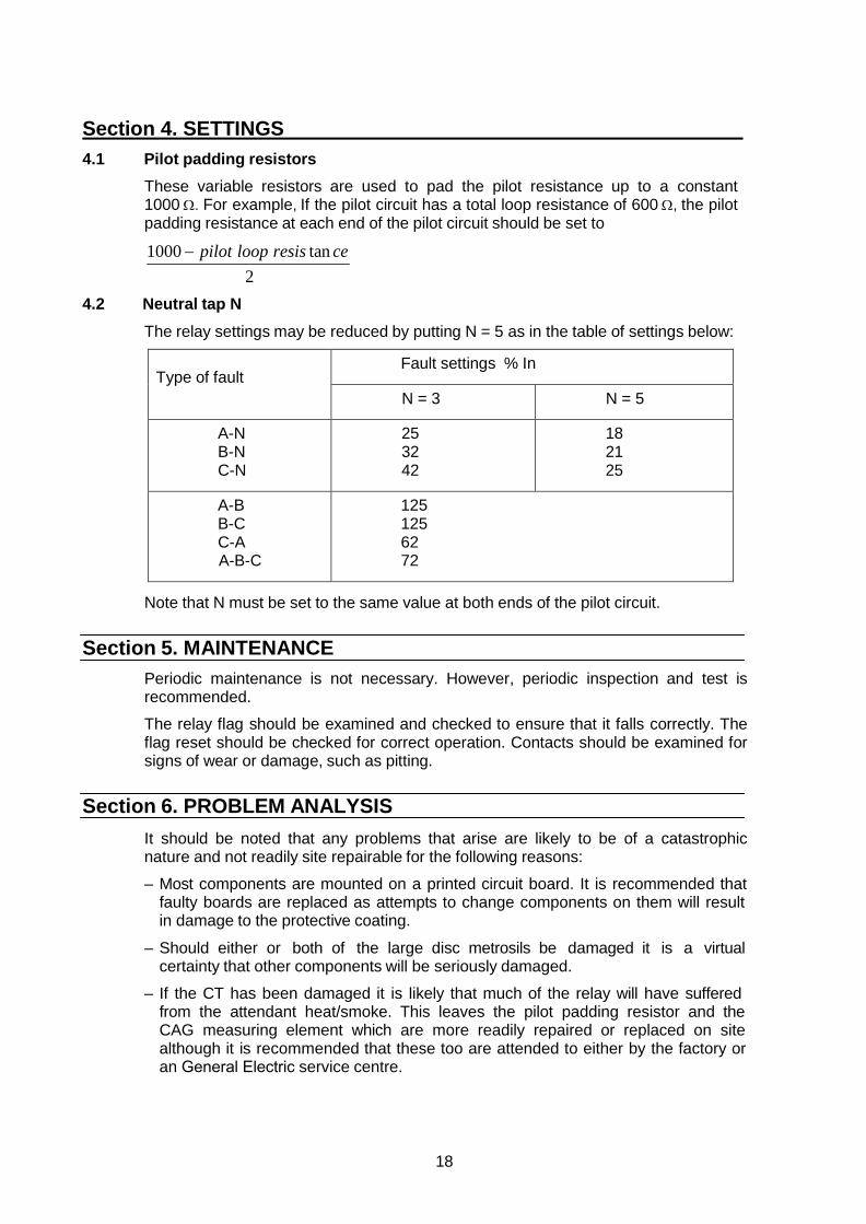
Section 4. SETTINGS 4.1 Pilot padding resistors
These variable resistors are used to pad the pilot resistance up to a constant 1000 Ω. For example, If the pilot circuit has a total loop resistance of 600 Ω, the pilot padding resistance at each end of the pilot circuit should be set to
1000 − pilot loop resis tan ce 2
4.2 Neutral tap N
The relay settings may be reduced by putting N = 5 as in the table of settings below:
Type of fault Fault settings % In
N = 3 N = 5
A-NB-NC-N
25 32 42
18 21 25
A-BB-CC-AA-B-C
125 125 62 72
Note that N must be set to the same value at both ends of the pilot circuit.
Section 5. MAINTENANCE Periodic maintenance is not necessary. However, periodic inspection and test is recommended.
The relay flag should be examined and checked to ensure that it falls correctly. The flag reset should be checked for correct operation. Contacts should be examined for signs of wear or damage, such as pitting.
Section 6. PROBLEM ANALYSIS It should be noted that any problems that arise are likely to be of a catastrophic nature and not readily site repairable for the following reasons:
– Most components are mounted on a printed circuit board. It is recommended that faulty boards are replaced as attempts to change components on them will result in damage to the protective coating.
– Should either or both of the large disc metrosils be damaged it is a virtual certainty that other components will be seriously damaged.
– If the CT has been damaged it is likely that much of the relay will have suffered from the attendant heat/smoke. This leaves the pilot padding resistor and the CAG measuring element which are more readily repaired or replaced on site although it is recommended that these too are attended to either by the factory or an General Electric service centre.
18
6.1
6.2
6.3
6.4
Removal of the relay from its case
To remove the relay from its case, loosen the cover nuts and remove the cover. The relay can now be withdrawn from the case by pulling on the handles. Pilot padding resistor Rpp
Connect the probes from a multimeter on the ohms range to the terminals on the variable resistor Rpp. Rotation of the knob between its limits should produce a resistance varying from zero to approximately 600Ω. If the variable resistor is found to be defective it may be replaced, remembering to lift the link between the terminals as for the original unit. The knob should be refitted to indicate 2.5 when the multimeter indicates 250Ω. The calibration should be check at 100Ω, 200Ω, 300Ω, 400Ω and 500Ω settings. All should be accurate within 5% or 10Ω, whichever is the greater. No further recalibration is necessary. CAG element If the flag fails to operate correctly it may be adjusted by gently bending the spring clip to the left of the armature. This should be set so that the flag falls just before the contacts close. This should not affect relay calibration.
If the coil or contacts are damaged it is strongly advised that the entire relay is returned for the remedial work to be performed, as the relay would have to be completely recalibrated in accordance with General Electric test specification reference Z7 MHOR04.
Spares
When ordering spares the serial number and model number of the relay should be included with the order.
Repairs
Should the need arise for the equipment to be returned to General Electric for repair, then the form at the back of this manual should be completed and sent with the equipment together with a copy of any commissioning test results.
19
_
A
B
C D1 D1
x Rp y
R1 R1 D2 D2
Operating coil
Operating coil
R1 x Rp y
v _
_
(a) _ _
v
v _
_ _
(b) v
(c) Point x Point y
(a) and (b) show the effective circuits during successive half cycles(c) indicates the voltages across relaying points x and y during one cycle
Figure 1 Behaviour of basic MHOR 04 circuit under external fault conditions when R1=Rp
20
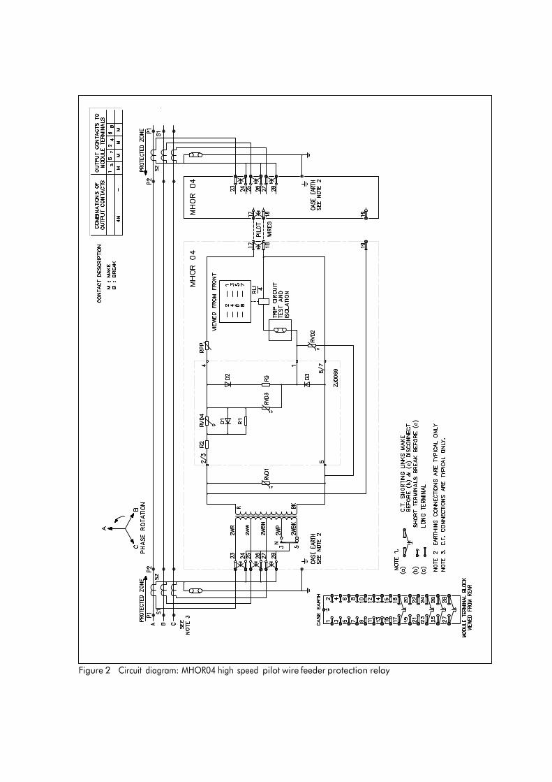
Figure 2 Circuit diagram: MHOR04 high speed pilot wire feeder protection relay
1A relay
0.235
5A relays
1.18 0.294 1.47 0.392 1.96 0.168 0.84 0.196 0.98 0.235 1.18 1.18 5.88 1.18 5.88
0.588 2.94 0.678 3.39
Actual nominal pick up current Injected phase Plugbridge
setting N Claimed setting as % of I rated
A - N 3 25 B - N 3 32 C - N 3 42 A - N 5 18 B - N 5 21 C - N 5 25 A - B - 125 B - C - 125 C - A - 62
A - B - C* - 72
* Reference only
Note: Site commissioning tolerances
The nominal setting currents given above are for resistive pilots of up to 1000 , but having little intercore capacitance. A commissioning tolerance of +10% should be allowed. An additional + 25% increase in operating current can be expected if intercore capacitance approaches 2.5mF.
Figure 3 Relay pick up settings, single-end injection
22
23
A
B Feeder
C Primary injection
test set
A1
Temporary 3Ø short circuit
23
24
25 MHOR 04
26
27
28 A2
Figure 4 Inter-phase relative polarity test of CTts
Low voltage battery (–ve on feeder inside)
+ –
A
B Feeder
C
The dc m/ammeter should give a +ve flick on making SI, and a –ve flick +
on breaking repeat similarly for other – mA
CTs.
23
24
25 MHOR04
26
27
28
Figure 5 CT polarity dc 'flick, test

24
Section 7. COMMISSIONING TEST RECORD
Relay Serial No Model No
Station Circuit Ref
Remote End Details:
Serial No Model No
Remote Station
Neutral Connection: N = 3 N = 5
3.2.1.2 Measured pilot loop resistance
3.2.2.1 Pilot padding resistor Rp set to
Local end secondary injection tests:
3.2.2.2 Open circuit pilot A-N pick up A
3.2.2.3 A-N pick up:
Pilots correct
Pilots reversed
A
A
Pilot I
Pilot I
mA
mA
3.2.2.4 Record of pick up settings:
Nominal pick up as a percentage of rated current
Injected I A-N B-N C-N A-B B-C C-A
N = 3 25 32 42 125 125 62
N = 5 18 21 25 125 125 62
Actual pick up current (Amps)
A-N B-N C-N A-B B-C C-A
Remote end pick up I (A-N only) A
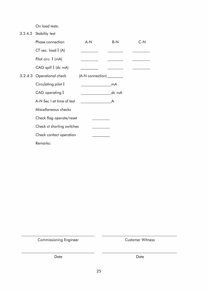
On load tests:
3.2.4.2 Stability test
Phase connection A-N B-N C-N
CT sec. load I (A)
Pilot circ. I (mA)
CAG spill I (dc mA)
3.2.4.3 Operational check (A-N connection)
Circulating pilot I
CAG operating I
mA
dc mA
A-N Sec I at time of test A
Miscellaneous checks
Check flag operate/reset
Check ct shorting switches
Check contact operation
Remarks:
Commissioning Engineer Customer Witness
Date Date
25

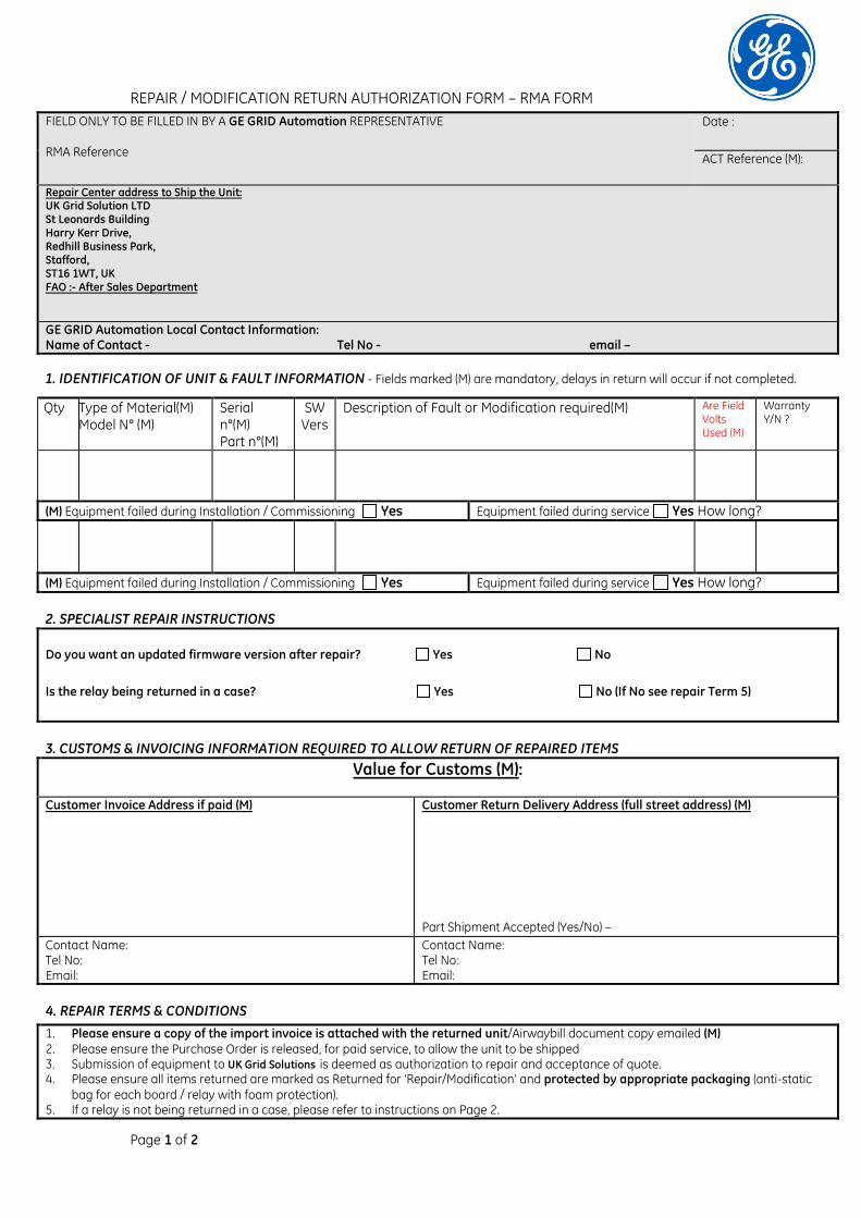
Page 1 of 2
REPAIR / MODIFICATION RETURN AUTHORIZATION FORM – RMA FORM FIELD ONLY TO BE FILLED IN BY A GE GRID Automation REPRESENTATIVE RMA Reference
Date :
ACT Reference (M):
Repair Center address to Ship the Unit: UK Grid Solution LTD St Leonards Building Harry Kerr Drive, Redhill Business Park, Stafford, ST16 1WT, UK FAO :- After Sales Department GE GRID Automation Local Contact Information: Name of Contact - Tel No - email – 1. IDENTIFICATION OF UNIT & FAULT INFORMATION - Fields marked (M) are mandatory, delays in return will occur if not completed.
Qty Type of Material(M) Model N° (M)
Serial n°(M) Part n°(M)
SW Vers
Description of Fault or Modification required(M)
Are Field Volts Used (M)
Warranty Y/N ?
(M) Equipment failed during Installation / Commissioning Yes Equipment failed during service Yes How long?
(M) Equipment failed during Installation / Commissioning Yes Equipment failed during service Yes How long?
2. SPECIALIST REPAIR INSTRUCTIONS
Do you want an updated firmware version after repair? Yes No
Is the relay being returned in a case? Yes No (If No see repair Term 5)
3. CUSTOMS & INVOICING INFORMATION REQUIRED TO ALLOW RETURN OF REPAIRED ITEMS Value for Customs (M):
Customer Invoice Address if paid (M)
Customer Return Delivery Address (full street address) (M) Part Shipment Accepted (Yes/No) –
Contact Name: Tel No: Email:
Contact Name: Tel No: Email:
4. REPAIR TERMS & CONDITIONS 1. Please ensure a copy of the import invoice is attached with the returned unit/Airwaybill document copy emailed (M) 2. Please ensure the Purchase Order is released, for paid service, to allow the unit to be shipped 3. Submission of equipment to UK Grid Solutions is deemed as authorization to repair and acceptance of quote. 4. Please ensure all items returned are marked as Returned for ‘Repair/Modification’ and protected by appropriate packaging (anti-static
bag for each board / relay with foam protection). 5. If a relay is not being returned in a case, please refer to instructions on Page 2.
Page 2 of 2
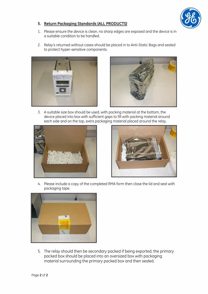
5. Return Packaging Standards (ALL PRODUCTS)
1. Please ensure the device is clean, no sharp edges are exposed and the device is in a suitable condition to be handled.
2. Relay’s returned without cases should be placed in to Anti-Static Bags and sealed
to protect hyper-sensitive components.
3. A suitable size box should be used, with packing material at the bottom, the device placed into box with sufficient gaps to fill with packing material around each side and on the top, extra packaging material placed around the relay.
4. Please include a copy of the completed RMA form then close the lid and seal with packaging tape.
5. The relay should then be secondary packed if being exported, the primary packed box should be placed into an oversized box with packaging material surrounding the primary packed box and then sealed.


Imagination at work
Grid Solutions St Leonards Building Redhill Business Park Stafford, ST16 1WT, UK +44 (0) 1785 250 070 www.gegridsolutions.com/contact
© 2017 General Electric. All rights reserved. Information contained in this document is indicative only. No representation or warranty is given or should be relied on that it is complete or correct or will apply to any particular project. This will depend on the technical and commercial circumstances. It is provided without liability and is subject to change without notice. Reproduction, use or disclosure to third parties, without express written authority, is strictly prohibited.
R8042K