Embed Size (px)
Citation preview
B5--1
CONTENTS
Type E/DOUBLE--INTERLOCK/Type K/TAFFeatures/Benefits
Type E B5--2 & B5--3. . . . . . . . . . . . . . . . . . . . . . . . . . . . . . . . . . . . . . . .Double-Interlock & Type K B5--2 & B5--4. . . . . . . . . . . . . . . . . . . . . . .TAF B5--2 & B5--5. . . . . . . . . . . . . . . . . . . . . . . . . . . . . . . . . . . . . . . . . .
Specifications B5--7. . . . . . . . . . . . . . . . . . . . . . . . . . . . . . . . . . . . . . . . . . .How To Order B5--8. . . . . . . . . . . . . . . . . . . . . . . . . . . . . . . . . . . . . . . . . . .Nomenclature B5--10. . . . . . . . . . . . . . . . . . . . . . . . . . . . . . . . . . . . . . . . . .Selection -- (Inch) B5--11. . . . . . . . . . . . . . . . . . . . . . . . . . . . . . . . . . . . . . .Easy Selection Table B5--15. . . . . . . . . . . . . . . . . . . . . . . . . . . . . . . . . . . .Engineering/Technical B5--17. . . . . . . . . . . . . . . . . . . . . . . . . . . . . . . . . . .Selection/Dimensions -- Inch
Type E B5--22. . . . . . . . . . . . . . . . . . . . . . . . . . . . . . . . . . . . . . . . . . . . . .Pillow Block B5--22. . . . . . . . . . . . . . . . . . . . . . . . . . . . . . . . . . . . . .Flanges B5--26. . . . . . . . . . . . . . . . . . . . . . . . . . . . . . . . . . . . . . . . .Take--Ups B5--30. . . . . . . . . . . . . . . . . . . . . . . . . . . . . . . . . . . . . . .
Type K B5--34. . . . . . . . . . . . . . . . . . . . . . . . . . . . . . . . . . . . . . . . . . . . . .Pillow Blocks B5--34. . . . . . . . . . . . . . . . . . . . . . . . . . . . . . . . . . . . .Flanges B5--36. . . . . . . . . . . . . . . . . . . . . . . . . . . . . . . . . . . . . . . . .Inner Units B5--38. . . . . . . . . . . . . . . . . . . . . . . . . . . . . . . . . . . . . . .Take--Ups B5--40. . . . . . . . . . . . . . . . . . . . . . . . . . . . . . . . . . . . . . .
Double-Interlock B5--44. . . . . . . . . . . . . . . . . . . . . . . . . . . . . . . . . . . . .Pillow Blocks B5--44. . . . . . . . . . . . . . . . . . . . . . . . . . . . . . . . . . . . .Flanges B5--48. . . . . . . . . . . . . . . . . . . . . . . . . . . . . . . . . . . . . . . . .Inner Units B5--50. . . . . . . . . . . . . . . . . . . . . . . . . . . . . . . . . . . . . . .
TAF B5--52. . . . . . . . . . . . . . . . . . . . . . . . . . . . . . . . . . . . . . . . . . . . . . . .Pillow Blocks B5--44. . . . . . . . . . . . . . . . . . . . . . . . . . . . . . . . . . . . .Inner Units B5--56. . . . . . . . . . . . . . . . . . . . . . . . . . . . . . . . . . . . . . .
Modifications/AccessoriesType E End Closures and E--TECT Seals B5--58. . . . . . . . . . . . . . .Type K, Double--Interlock and TAF End Closuresand E--TECT Seals B5--60. . . . . . . . . . . . . . . . . . . . . . . . . . . . . . . . . . .
Selection -- Metric B5--61. . . . . . . . . . . . . . . . . . . . . . . . . . . . . . . . . . . . . . .Engineering/Technical -- Metric B5--62. . . . . . . . . . . . . . . . . . . . . . . . . . .Selection/Dimensions -- Metric
Type E -- Metric B5--68. . . . . . . . . . . . . . . . . . . . . . . . . . . . . . . . . . . . . .Plummer Blocks B5--68. . . . . . . . . . . . . . . . . . . . . . . . . . . . . . . . . .
Part Number Index INDEX--1. . . . . . . . . . . . . . . . . . . . . . . . . . . . . . . . . . . . . . . . .
Keyword Index INDEX--28. . . . . . . . . . . . . . . . . . . . . . . . . . . . . . . . . . . . . . . . . . . . .
B5--2
FEATURES/BENEFITS
General Features:¯ Factory assembled, adjusted
and pre-lubricated
¯ Case hardened rollers andraces
¯ Easy installation andmaintenance
¯ 65 degree set screw angleSpringlok collar/flingers—More holding power than 90or 120 degree
¯ Single rubber lip contactingseals
Type E/DOUBLE--INTERLOCK/Type K/TAF
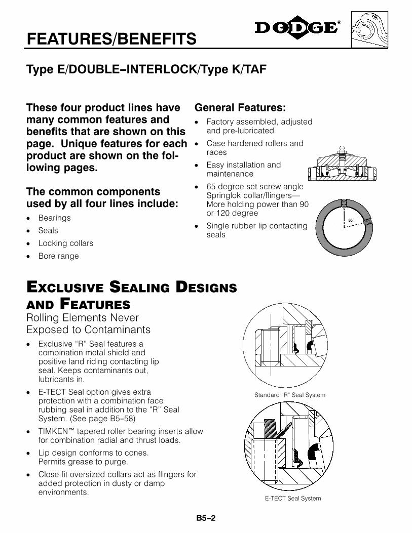
These four product lines havemany common features andbenefits that are shown on thispage. Unique features for eachproduct are shown on the fol-lowing pages.
The common componentsused by all four lines include:¯ Bearings
¯ Seals
¯ Locking collars
¯ Bore range
Rolling Elements NeverExposed to Contaminants¯ Exclusive “R” Seal features a
combination metal shield andpositive land riding contacting lipseal. Keeps contaminants out,lubricants in.
¯ E-TECT Seal option gives extraprotection with a combination facerubbing seal in addition to the “R” SealSystem. (See page B5--58)
¯ TIMKEN tapered roller bearing inserts allowfor combination radial and thrust loads.
¯ Lip design conforms to cones.Permits grease to purge.
¯ Close fit oversized collars act as flingers foradded protection in dusty or dampenvironments.
EXCLUSIVE SEALING DESIGNSAND FEATURES
Standard “R” Seal System
E-TECT Seal System

B5--3
FEATURES/BENEFITS
Type E
DODGE Type EOne Bearing, One SealFor Dusty or Damp Environments
¯̄̄̄ “E” stands for economy¯ Type E allows easy upgrade from
ball bearings
¯ Interchangeable mountingdimensions with ball bearings
¯ Moderate price premium vs. ballbearings
¯ Steel housed pillow blocks availablein selected sizes.
The Original DODGE Type EBearing, Only Better¯ Provides added protection against
contamination
¯ Completely assembled, factory adjustedand properly lubricated - shaft ready
¯ Stocked in all configurations
¯ Extra protection—E-TECT seal option
¯ Stainless end covers available up to 3″,75mm bore
Pillow Block13/16 - 7″
35 - 180 mm
Piloted flange13/16 - 5″
35 - 125 mm
Flange13/16 - 41/2″35 - 115 mm
Top angle take-ups13/4 - 4″
45 - 100 mm
Center pull framewith wide slot take-up
13/8 - 3″35 - 75mm
B5--4
FEATURES/BENEFITS
Type K and DOUBLE--INTERLOCK
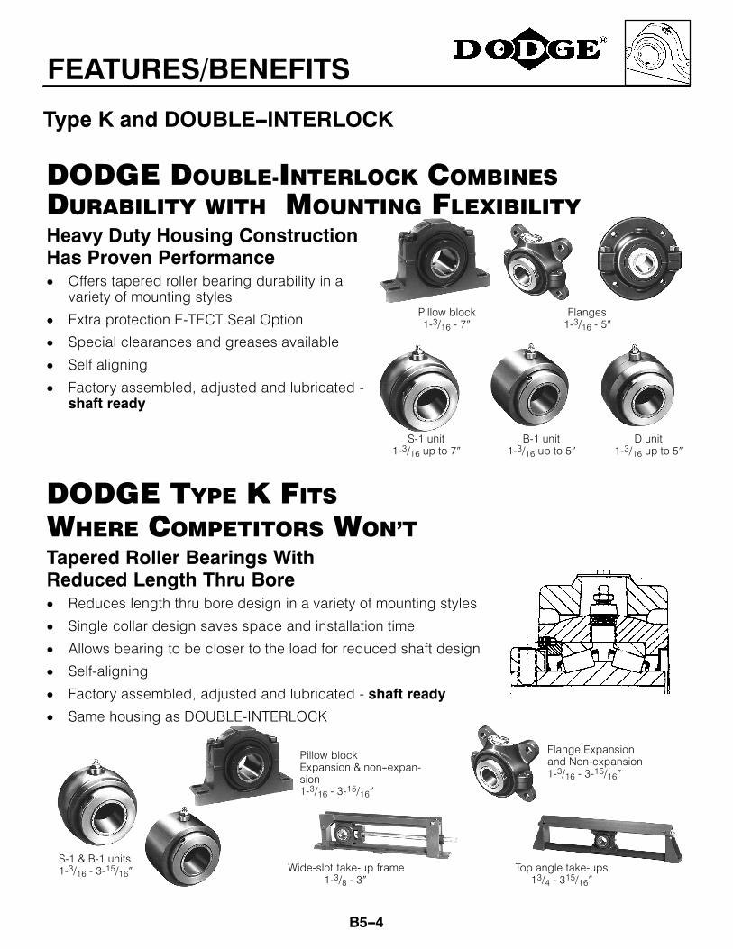
Heavy Duty Housing ConstructionHas Proven Performance¯ Offers tapered roller bearing durability in a
variety of mounting styles
¯ Extra protection E-TECT Seal Option
¯ Special clearances and greases available
¯ Self aligning
¯ Factory assembled, adjusted and lubricated -shaft ready
DODGE DOUBLE-INTERLOCK COMBINESDURABILITY WITH MOUNTING FLEXIBILITY
DODGE TYPE K FITSWHERE COMPETITORS WON’T
Pillow block1-3/16 - 7″
S-1 unit1-3/16 up to 7″
B-1 unit1-3/16 up to 5″
D unit1-3/16 up to 5″
Tapered Roller Bearings WithReduced Length Thru Bore¯ Reduces length thru bore design in a variety of mounting styles
¯ Single collar design saves space and installation time
¯ Allows bearing to be closer to the load for reduced shaft design
¯ Self-aligning
¯ Factory assembled, adjusted and lubricated - shaft ready
¯ Same housing as DOUBLE-INTERLOCK
S-1 & B-1 units1-3/16 - 3-15/16″
Flange Expansionand Non-expansion1-3/16 - 3-15/16″
Pillow blockExpansion & non--expan-sion1-3/16 - 3-15/16″
Flanges1-3/16 - 5″
Wide-slot take-up frame1-3/8 - 3″
Top angle take-ups13/4 - 315/16″
B5--5
FEATURES/BENEFITS
TAF
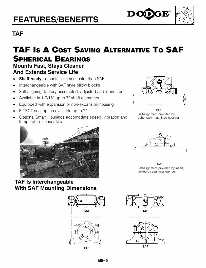
TAF IS A COST SAVING ALTERNATIVE TO SAFSPHERICAL BEARINGSMounts Fast, Stays CleanerAnd Extends Service Life¯ Shaft ready - mounts six times faster than SAF
¯ Interchangeable with SAF style pillow blocks
¯ Self-aligning, factory assembled, adjusted and lubricated
¯ Available in 1-7/16″ up to 7″ shaft diameters
¯ Equipped with expansion or non-expansion housing
¯ E-TECT seal option available up to 7″
¯ Optional Smart Housings accomodate speed, vibration andtemperature sensor kits
TAF Is InterchangeableWith SAF Mounting Dimensions
TAF
SAF
Self-alignment provided byspherically machined housing.
Self-alignment provided by insert,limited by seal interference.
SAF
SAF
TAF
TAF

B5--6
FEATURES/BENEFITS
Type K/DOUBLE--INTERLOCK/TAF
DODGE BEARINGS SAVE YOU TIME AND MONEY
Standard SAF¯ Four prices
¯ Up to six packages
¯ Open bearing
¯ Feeler gauge required
¯ Grease required
DODGE TAF, Type K and DOUBLE-INTERLOCK¯ One price
¯ Sealed bearing
¯ Factory adjusted
¯ Factory lubricated
¯̄̄̄ Shaft ready
Compare Standard SAF and DODGE Sealing Designs
Compare These DODGE TAF, Type K & DOUBLE-INTERLOCK BearingAdvantages Against Standard SAF Pillow Blocks
DODGE TAF, TYPE K, DOUBLE-INTERLOCK
¯ Inner unit carries seal
¯ Up to 5° staticmisalignment
¯ Seal and bearing ridetogether in inner unit
¯ Seals maintain contact oncones even withmisalignment
STANDARD SAF¯ Seals ride
independently ofbearing
¯ Less than 1° staticmisalignment
¯ Sealing effectivenessdecreases asmisalignmentincreases
¯ Seals distort whenmisalignment occurs
B5--7
SPECIFICATION
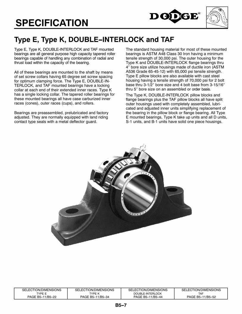
Type E, Type K, DOUBLE--INTERLOCK and TAFType E, Type K, DOUBLE-INTERLOCK and TAF mountedbearings are all general purpose high capacity tapered rollerbearings capable of handling any combination of radial andthrust load within the capacity of the bearing.
All of these bearings are mounted to the shaft by meansof set screw collars having 65 degree set screw spacingfor optimum clamping force. The Type E, DOUBLE-IN-TERLOCK, and TAF mounted bearings have a lockingcollar at each end of their extended inner races. Type Khas a single locking collar. The tapered roller bearings forthese mounted bearings all have case carburized innerraces (cones), outer races (cups), and rollers.
Bearings are preassembled, prelubricated and factoryadjusted. They are normally equipped with land ridingcontact type seals with a metal deflector guard.
The standard housing material for most of these mountedbearings is ASTM A48 Class 30 Iron having a minimumtensile strength of 30,000 psi. The outer housing for theType K and DOUBLE-INTERLOCK flange bearings thru4″ bore size utilize housings made of ductile iron (ASTMA536 Grade 65-45-12) with 65,000 psi tensile strength.Type E pillow blocks are also available with cast steelhousing having a tensile strength of 70,000 psi for 2 boltbase thru 3-1/2″ bore size and 4 bolt base from 3-15/16″thru 5″ bore size on an assembled or order basis.The Type K, DOUBLE-INTERLOCK pillow blocks andflange bearings plus the TAF pillow blocks all have splitouter housings used with completely assembled, lubri-cated and adjusted inner units simplifying replacement ofthe bearing in the pillow block or flange bearing. All TypeE mounted bearings, Type K take up units and all D units,S-1 units, and B-1 units have solid one piece housings.
SELECTION/DIMENSIONSTYPE E
PAGE B5--11/B5--22
SELECTION/DIMENSIONSTYPE K
PAGE B5--11/B5--34
SELECTION/DIMENSIONSDOUBLE-INTERLOCKPAGE B5--11/B5--44
SELECTION/DIMENSIONSTAF
PAGE B5--11/B5--52
B5--8
HOW TO ORDER
Type E, Type K, DOUBLE--INTERLOCK and TAFThere are two ways to specify DODGE Bearings. Most ofthe product offering have part numbers with listingsshown throughout this catalog. Use of part numbers en-sures accurate order processing.
When part numbers are not shown, the product may bespecified by description or part name. This method isused when ordering units that include modifications oroptions. To order by description, use the nomenclaturekey shown on page B5--10 and add any special instruc-tions to the end of the description for options not coveredby the nomenclature.
SPECIAL BEARING REQUIREMENTS ANDSPECIAL LUBRICANTSDODGE Bearings are factory adjusted and pre-lubricated.For applications where extreme ambient temperatures, highspeeds or high loads are expected, a variety of specialtylubricants and adjustments are available. Standard greaseprovided is Shell Alvania #2 up to 5″, 125mm bore. Above
5″ bore Mobil Mobilux #2EP is standard. High temperaturegreases available include Moluballoy 896 HT and MobilithSHC460. Other special lubricatns are available upon re-quest. Special lubricant options usually involve set-upcharges and premiums. To order, specify type of lubricantrequired at the end of the product name or after the stan-dard part number.
Example:F4B-E-207 except with Mobilith SHC 460 grease and.012 to .015 lateral end play
or023106 except with Mobilith SHC 460 grease and .012to .015 lateral end play
OTHER SPECIAL REQUIREMENTS NOTLISTEDFor applications requiring modifications not listed, we en-courage you to contact out Application Engineering Depart-ment for Bearings at 864-297-4800.
FEATURES/BENEFITSPAGE B5--2
SPECIFICATIONSPAGE B5--7
NOMENCLATUREPAGE B5--10
SELECTIONPAGE B5--11
B5--9
HOW TO ORDER
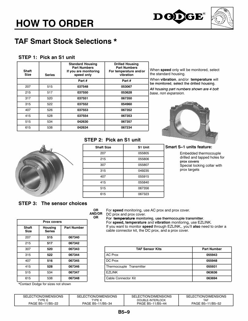
TAF Smart Stock Selections *
STEP 1: Pick an S1 unit
ShaftSize Series
Standard HousingPart Numbers
If you are monitoringspeed only
Drilled HousingPart Numbers
For temperature and/orvibration
When speed only will be monitored, selectthe standard housing.
Wh ib i d/ illPart # Part # When vibration, and/or temperature willbe monitored select the drilled housing
207 515 037548 053067be monitored, select the drilled housing.
All housing part numbers shown are 4 bolt215 517 037550 053628
All housing part numbers shown are 4 boltbase, non expansion.
317 520 037551 067350
315 522 037552 054960
407 526 037553 067352
415 528 037554 067353
515 534 042630 067357
615 538 042634 067234
STEP 2: Pick an S1 unitShaft Size S1 Unit Smart S--1 units feature:
207 055805 Embedded thermocoupled ill d d t d h l f215 055806
pdrilled and tapped holes forprox covers
307 055807prox coversSpecial locking collar with
315 049235
p gprox targets
407 055915
415 055840
515 067356
615 067323
STEP 3: The sensor choicesOR
AND/ORFor speed monitoring, use AC prox and prox cover.DC dAND/OR
OR
p g p pDC prox and prox cover.For temperature monitoring use thermocouple transmitter
Prox coversOR For temperature monitoring, use thermocouple transmitter.
For speed, temperature and vibration monitoring, use EZLINK.ShaftSize
HousingSeries
Part Number
p , p g,If you want to monitor speed through EZLINK,, you’ll also need to order acable connector kit, the DC prox, and a prox cover.
207 515 067340
215 517 067342
307 520 067343 TAF Sensor Kits Part Number
315 522 067344 AC Prox 055943
407 516 067345 DC Prox 055948
415 528 067346 Thermocouple Transmitter 055931
515 534 067347 EZLINK 063636
615 538 067348 Cable Connector Kit 063694
*Contact Dodge for sizes not shown
SELECTION/DIMENSIONSTYPE E
PAGE B5--11/B5--22
SELECTION/DIMENSIONSTYPE K
PAGE B5--11/B5--34
SELECTION/DIMENSIONSDOUBLE-INTERLOCKPAGE B5--11/B5--44
SELECTION/DIMENSIONSTAF
PAGE B5--11/B5--52
B5--10
NOMENCLATURE
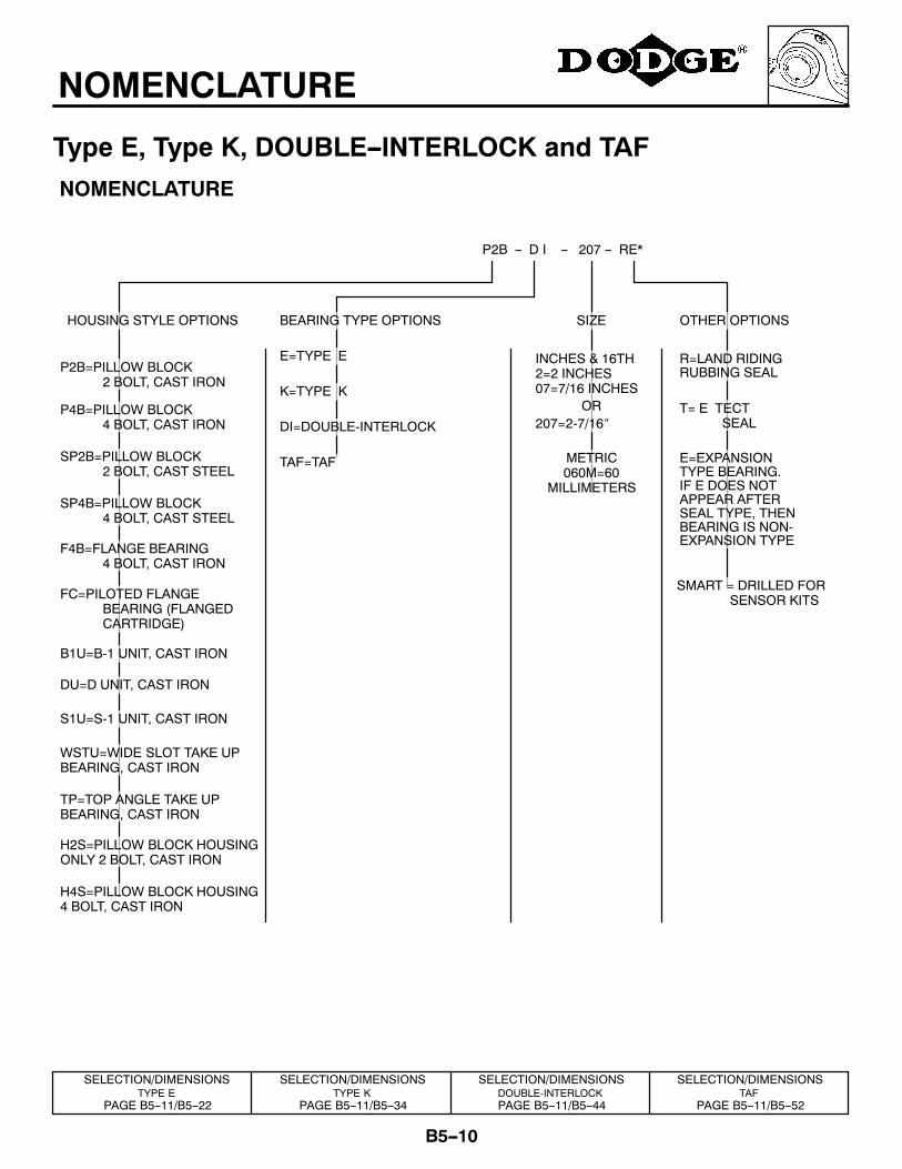
Type E, Type K, DOUBLE--INTERLOCK and TAF
BEARING TYPE OPTIONS
E=TYPE E
K=TYPE K
DI=DOUBLE-INTERLOCK
TAF=TAF
NOMENCLATURE
P2B -- D I -- 207 -- RE*
HOUSING STYLE OPTIONS
P2B=PILLOW BLOCK2 BOLT, CAST IRON
P4B=PILLOW BLOCK4 BOLT, CAST IRON
SP2B=PILLOW BLOCK2 BOLT, CAST STEEL
SP4B=PILLOW BLOCK4 BOLT, CAST STEEL
F4B=FLANGE BEARING4 BOLT, CAST IRON
FC=PILOTED FLANGEBEARING (FLANGEDCARTRIDGE)
B1U=B-1 UNIT, CAST IRON
DU=D UNIT, CAST IRON
S1U=S-1 UNIT, CAST IRON
WSTU=WIDE SLOT TAKE UPBEARING, CAST IRON
TP=TOP ANGLE TAKE UPBEARING, CAST IRON
SIZE
INCHES & 16TH2=2 INCHES07=7/16 INCHES
OR207=2-7/16″
METRIC060M=60
MILLIMETERS
OTHER OPTIONS
R=LAND RIDINGRUBBING SEAL
T= E TECTSEAL
E=EXPANSIONTYPE BEARING.IF E DOES NOTAPPEAR AFTERSEAL TYPE, THENBEARING IS NON-EXPANSION TYPE
H2S=PILLOW BLOCK HOUSINGONLY 2 BOLT, CAST IRON
H4S=PILLOW BLOCK HOUSING4 BOLT, CAST IRON
SMART = DRILLED FORSENSOR KITS
SELECTION/DIMENSIONSTYPE E
PAGE B5--11/B5--22
SELECTION/DIMENSIONSTYPE K
PAGE B5--11/B5--34
SELECTION/DIMENSIONSDOUBLE-INTERLOCKPAGE B5--11/B5--44
SELECTION/DIMENSIONSTAF
PAGE B5--11/B5--52
B5--11
SELECTION
Type E, Type K, DOUBLE--INTERLOCK And TAF Tapered RollerBearingsDODGE Type E, K, DI and TAF Double Row TaperedRoller Bearings have the capacity to carry heavy radialloads and combined radial and thrust loads. The maxi-mum recommended load which can be applied is limitedby various components in the system such as bearing,housing, shaft, shaft attachment, speed and life require-ments as listed in this catalog. DODGE tapered rollerbearings have been applied successfully even when theselimits have been exceeded under controlled operatingconditions. Contact DODGE Application Engineering(864) 297-4800 for applications which exceed the recom-mendations of this catalog.
L10 Hours Life --- The life which may be expected fromat least 90% of a given group of bearings operating underidentical conditions.
L10 = C90
P10∕3 x 1, 500, 000
RPM
Where: C90 = Dynamic Capacity (Table 1, pg.B5--14 ), lbs.P = Equivalent Radial Load, lbs.
GENERALHeavy Service --- For heavy shock loads, frequent shockloads, or severe vibrations, add up to 50% (according toseverity of conditions) to the Equivalent Radial Load. Con-sult DODGE Application Engineering for additional selec-tion assistance.
Thrust load values shown in the table below arerecommended as a guide for general applications that willgive adequate L10 life for pillow blocks. The maximumthrust load should not exceed values shown on Table 3.Where substantial radial load is also present, it isadvisable to calculate actual L10 life to assure that itmeets the requirements. The effectiveness of the shaftattachment to carry thrust load depends on propertightening of the setscrews, shaft tolerance and shaftdeflections. Therefore, it is advisable to use auxiliarythrust carrying devices such as shaft shoulder, snap ring
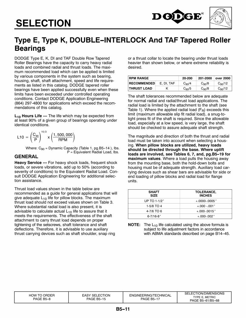
or a thrust collar to locate the bearing under thrust loadsheavier than shown below, or where extreme reliability isdesired.
RPM RANGE 20-200 201-2000 over 2000
RECOMMENDED E, DI, TAF C90/4 C90/8 C90/12
THRUST LOAD K C90/5 C90/8 C90/12
The shaft tolerances recommended below are adequatefor normal radial and radial/thrust load applications. Theradial load is limited by the attachment to the shaft (seeTable 1). Where the applied radial load (FR) exceeds thislimit (maximum allowable slip fit radial load), a snug-to-light press fit of the shaft is required. Since the allowableload, especially at a low speed, is very large, the shaftshould be checked to assure adequate shaft strength.
The magnitude and direction of both the thrust and radialload must be taken into account when selecting a hous-ing. When pillow blocks are utilized, heavy loadsshould be directed through the base. Where upliftloads are involved, see Tables 6, 7, and, pg.B5--19 formaximum values. Where a load pulls the housing awayfrom the mounting base, both the hold-down bolts andhousing must be of adequate strength. Auxiliary load car-rying devices such as shear bars are advisable for side orend loading of pillow blocks and radial load for flangeunits.
SHAFTSIZE
TOLERANCE,INCHES
UP TO 1-1/2″ +.0000-.0005 ″
1-5/8 TO 4 +.000 -.001″
4-7/6 TO 6 +.000-.0015 ″
6-7/16-8″ +.000-.002 ″
NOTE: The L10 life calculated using the above formula issubject to life adjustment factors in accordancewith ABMA standards described on page B14--45.
HOW TO ORDERPAGE B5--8
EASY SELECTIONPAGE B5--15
ENGINEERING/TECHNICALPAGE B5--17
SELECTION/DIMENSIONSTYPE E, METRIC
PAGE B5--61/B5--68
B5--12
SELECTION
Type E, Type K, DOUBLE--INTERLOCK And TAF Tapered RollerBearingsSELECTING BEARINGS SUPPORTING RA-DIAL LOADS ONLY
1. Define L10 Life Hours desired.
2. Establish bearing radial load, FR(FR = P for Pure Radial Load Conditions).The DODGE program BESTt* can beused to find application loads.
3. Establish RPM.
Using the easy selection Table 2, pg. B5--15 find, underthe RPM column, the equivalent radial load that equals oris higher than the application radial load for the desiredlife. The shaft size on the far left will be the minimumshaft size that you can use for your application. If the de-sired life is different than the values shown on the chart,use alternate Method A shown below.
Example: 1. L10 Life = 30,000 Hours2. Radial load = 3800 lbs.3. RPM = 1,000
At the intersection of the 1,000 RPM column and the30,000 hours L10 life row, the equivalent radial load of3910 lbs. exceeds the 3800 lbs. radial load for shaft sizes2-11/16″-3″. A bearing with bore ranging from 2-11/16″ to3″ may be used for this application.
ALTERNATE METHOD A ---SELECTING A BEARING FOR AN L10 LIFEVALUE NOT SHOWN IN THE EASY SELEC-TION CHART.The L10 life equation can be rearranged so that the bear-ing dynamic capacity C90 is identified in terms of L10,RPM and P.
C90 = L10 x RPM1, 500, 0000.3 x P
(P = FR for Pure Radial Load Conditions)
Since the L10, RPM, and P are known, solve for C90. Se-lect from the dynamic capacity column on Table 1,pg.B5--14 the C90 value equal to or greater than the C90value just calculated. The bore size on the far left repre-sents the bore size selection. Check that the applicationRPM does not exceed the MAX. RPM on Table 1. Alsocheck that the radial load does not exceed the MaximumAllowable Slip Fit Radial Load shown on Table 1. If itdoes, a line to line to light press fit of shaft is required.When selecting an L10 life of less than 30,000 hours, par-ticular attention must be paid to shaft deflection and prop-er lubricant selection.
SELECTING BEARINGS SUPPORTING COM-BINATION RADIAL AND THRUST LOADSWhen a bearing supports both a radial load and a thrustload, the loading on the two rows is shared unequally de-pending on the ratio of thrust to radial load. The use of theX (radial factor) and Y (thrust factor) from Table 1 con-verts the applied thrust load and radial loads to an equiva-lent radial load having the same effect on the life of thebearing as a radial load of this magnitude.
The equivalent radial load P = XFR +YFA
Where: P= Equivalent radial load, lbs.FR= Radial load, lbs.(see Table 1 for allowableslip fit maximum)FA= Thrust (axial) load, lbs.e = Thrust load to radial load factor (Table 1)X = Radial load factor (Table 1)Y= Thrust load factor (Table 1)
To find X and Y, calculate FA/FR and compare to e for theselected bore size. Determine X and Y from Table 1, pg.B5--14 depending on whether FA/FR is equal to or lessthan e, or FA/FR is greater than e. Substitute all knownvalues into the equivalent radial load equation. P (equiva-lent radial load) can be used in the life formula to deter-mine L10, or it can be compared to the allowable equiva-lent radial load ratings for the speed and hours life desiredin the easy selection Table 2, pg. B5--15.
*The DODGE Bearing Evaluation and Selection Tech-nique (BEST) is a menu driven computer program thatcalculates bearing loads, fatigue life and operating tem-perature for a two bearing shaft system based on usersupplied input parameters. To order, call (864) 287-4800.
SELECTION/DIMENSIONSTYPE E
PAGE B5--11/B5--22
SELECTION/DIMENSIONSTYPE K
PAGE B5--11/B5--34
SELECTION/DIMENSIONSDOUBLE-INTERLOCKPAGE B5--11/B5--44
SELECTION/DIMENSIONSTAF
PAGE B5--11/B5--52
B5--13
SELECTION
Type E, Type K, DOUBLE--INTERLOCK and TAFSELECTING BEARINGS SUPPORTING ONLYTHRUST LOADSTapered Roller Bearings perform extremely well under purethrust load applications. Use P = YFA for the equivalent ra-dial load. The value of Y is obtained from Table 1, pg.B5--14 for FA/FR>e. Substitute Y and FA into the equivalentload equation. P (equivalent radial load) can be used in thelife formula to determine L10 or it can be compared to theallowable equivalent radial load ratings for the speed andhours life desired in the easy selection Table 2, pg. B5--15.
LUBRICATIONDODGE E, K, DI, and TAF tapered roller bearings up to 5″bore are lubricated at the factory with Shell Alvania #2grease. Above 5″ bore they are lubricated with Mobil Mobi-
lux #2EP. Shell Alvania #2 and Mobil Mobilux #2EP greasesare superior industrial greases using a lithium hydroxystea-rate thickener and highly refined base oil. These greases willadequately handle low and medium speeds with low andmedium loads at normal temperatures as defined on Table5, pg.B5--18. For very low and high speeds, for heavy loadsand for low and high temperatures, special greases must beused. Contact DODGE Application Engineering(864) 297-4800. DODGE engineers will recommend bear-ings and lubricants for the above unusual conditions.DODGE also has the expertise to custom design and buildspecial bearings for your needs. The only maintenance re-quirement for DODGE Tapered Roller Bearings is periodicrelubrication at regular intervals as outlined in the appropri-ate instruction manuals.
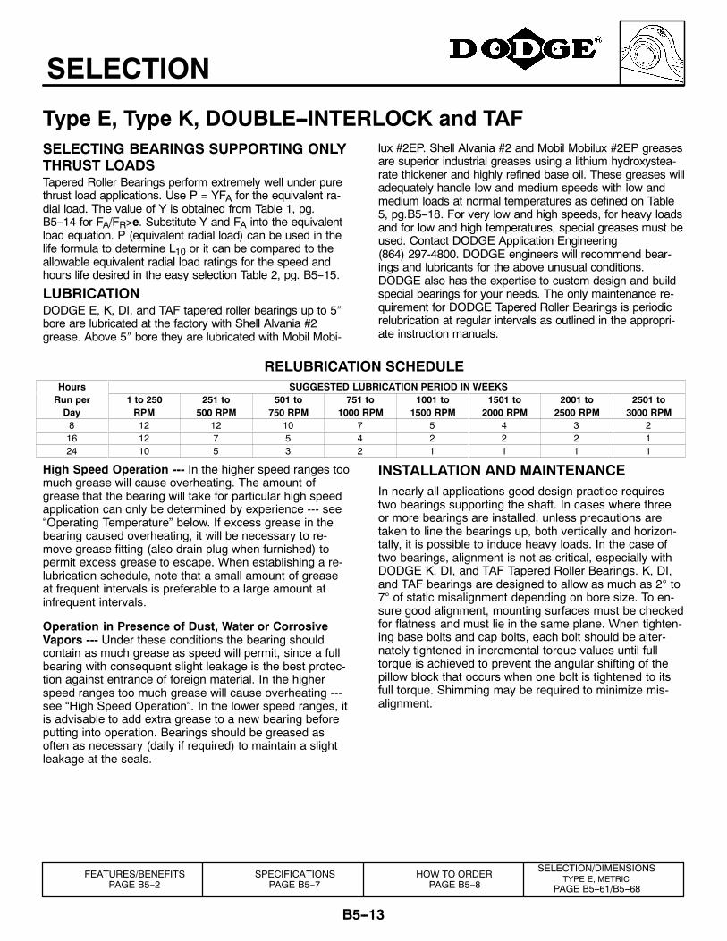
RELUBRICATION SCHEDULEHours SUGGESTED LUBRICATION PERIOD IN WEEKSRun per 1 to 250 251 to 501 to 751 to 1001 to 1501 to 2001 to 2501 toDay RPM 500 RPM 750 RPM 1000 RPM 1500 RPM 2000 RPM 2500 RPM 3000 RPM8 12 12 10 7 5 4 3 216 12 7 5 4 2 2 2 124 10 5 3 2 1 1 1 1
High Speed Operation --- In the higher speed ranges toomuch grease will cause overheating. The amount ofgrease that the bearing will take for particular high speedapplication can only be determined by experience --- see“Operating Temperature” below. If excess grease in thebearing caused overheating, it will be necessary to re-move grease fitting (also drain plug when furnished) topermit excess grease to escape. When establishing a re-lubrication schedule, note that a small amount of greaseat frequent intervals is preferable to a large amount atinfrequent intervals.
Operation in Presence of Dust, Water or CorrosiveVapors --- Under these conditions the bearing shouldcontain as much grease as speed will permit, since a fullbearing with consequent slight leakage is the best protec-tion against entrance of foreign material. In the higherspeed ranges too much grease will cause overheating ---see “High Speed Operation”. In the lower speed ranges, itis advisable to add extra grease to a new bearing beforeputting into operation. Bearings should be greased asoften as necessary (daily if required) to maintain a slightleakage at the seals.
INSTALLATION AND MAINTENANCEIn nearly all applications good design practice requirestwo bearings supporting the shaft. In cases where threeor more bearings are installed, unless precautions aretaken to line the bearings up, both vertically and horizon-tally, it is possible to induce heavy loads. In the case oftwo bearings, alignment is not as critical, especially withDODGE K, DI, and TAF Tapered Roller Bearings. K, DI,and TAF bearings are designed to allow as much as 2° to7° of static misalignment depending on bore size. To en-sure good alignment, mounting surfaces must be checkedfor flatness and must lie in the same plane. When tighten-ing base bolts and cap bolts, each bolt should be alter-nately tightened in incremental torque values until fulltorque is achieved to prevent the angular shifting of thepillow block that occurs when one bolt is tightened to itsfull torque. Shimming may be required to minimize mis-alignment.
SELECTION/DIMENSIONSTYPE E, METRIC
PAGE B5--61/B5--68
FEATURES/BENEFITSPAGE B5--2
SPECIFICATIONSPAGE B5--7
HOW TO ORDERPAGE B5--8
B5--14
SELECTION
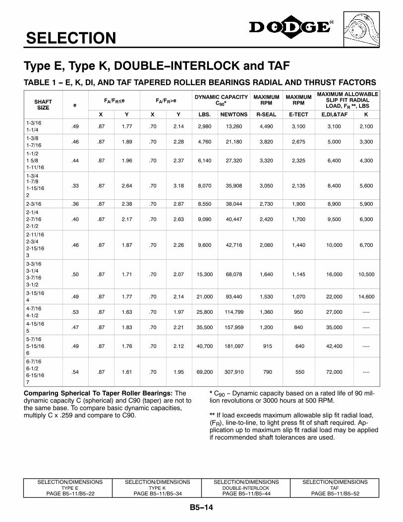
Type E, Type K, DOUBLE--INTERLOCK and TAFTABLE 1 -- E, K, DI, AND TAF TAPERED ROLLER BEARINGS RADIAL AND THRUST FACTORS
SHAFTSIZE e
FA/FR<e FA/FR>eDYNAMIC CAPACITY
C90*MAXIMUM
RPMMAXIMUM
RPM
MAXIMUM ALLOWABLESLIP FIT RADIALLOAD, FR **, LBSSIZE
X Y X Y LBS. NEWTONS R-SEAL E-TECT E,DI,&TAF K
1-3/161-1/4
.49 .87 1.77 .70 2.14 2,980 13,260 4,490 3,100 3,100 2,100
1-3/81-7/16
.46 .87 1.89 .70 2.28 4,760 21,180 3,820 2,675 5,000 3,300
1-1/21 5/81-11/16
.44 .87 1.96 .70 2.37 6,140 27,320 3,320 2,325 6,400 4,300
1-3/41-7/81-15/162
.33 .87 2.64 .70 3.18 8,070 35,908 3,050 2,135 8,400 5,600
2-3/16 .36 .87 2.38 .70 2.87 8,550 38,044 2,730 1,900 8,900 5,900
2-1/42-7/162-1/2
.40 .87 2.17 .70 2.63 9,090 40,447 2,420 1,700 9,500 6,300
2-11/162-3/42-15/163
.46 .87 1.87 .70 2.26 9,600 42,716 2,060 1,440 10,000 6,700
3-3/163-1/43-7/163-1/2
.50 .87 1.71 .70 2.07 15,300 68,078 1,640 1,145 16,000 10,500
3-15/164
.49 .87 1.77 .70 2.14 21,000 93,440 1,530 1,070 22,000 14,600
4-7/164-1/2
.53 .87 1.63 .70 1.97 25,800 114,799 1,360 950 27,000 ----
4-15/165
.47 .87 1.83 .70 2.21 35,500 157,959 1,200 840 35,000 ----
5-7/165-15/166
.49 .87 1.76 .70 2.12 40,700 181,097 915 640 42,400 ----
6-7/166-1/26-15/167
.54 .87 1.61 .70 1.95 69,200 307,910 790 550 72,000 ----
Comparing Spherical To Taper Roller Bearings: Thedynamic capacity C (spherical) and C90 (taper) are not tothe same base. To compare basic dynamic capacities,multiply C x .259 and compare to C90.
* C90 -- Dynamic capacity based on a rated life of 90 mil-lion revolutions or 3000 hours at 500 RPM.
** If load exceeds maximum allowable slip fit radial load,(FR), line-to-line, to light press fit of shaft required. Ap-plication up to maximum slip fit radial load may be appliedif recommended shaft tolerances are used.
SELECTION/DIMENSIONSTYPE E
PAGE B5--11/B5--22
SELECTION/DIMENSIONSTYPE K
PAGE B5--11/B5--34
SELECTION/DIMENSIONSDOUBLE-INTERLOCKPAGE B5--11/B5--44
SELECTION/DIMENSIONSTAF
PAGE B5--11/B5--52
B5--15
SELECTION
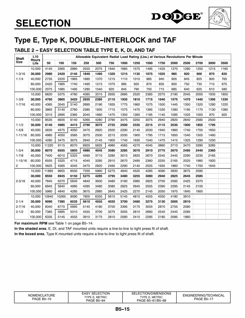
Type E, Type K, DOUBLE--INTERLOCK and TAFTABLE 2 -- EASY SELECTION TABLE TYPE E, K, DI, AND TAF
Shaft L10Hours
Allowable Equivalent Radial Load Rating (Lbs.) at Various Revolutions Per MinuteShaftSize Hours
Life 50 100 150 250 500 750 1000 1250 1500 1750 2000 2500 2700 3000 3500
10,000 4145 3365 2980 2555 2075 1840 1685 1575 1495 1425 1370 1280 1250 1215 1160
1-3/16 30,000 2980 2420 2145 1840 1495 1320 1215 1135 1075 1025 985 920 900 870 835
1-1/4 40,000 2735 2220 1965 1685 1370 1215 1110 1010 985 940 905 845 825 800 765
60,000 2420 1965 1740 1495 1215 1075 985 920 870 835 800 750 730 710 675
100,000 2075 1685 1495 1280 1040 920 845 790 750 715 685 640 625 610 580
10,000 6620 5375 4760 4085 3315 2935 2695 2520 2385 2275 2190 2045 2000 1935 1850
1-3/8 30,000 4760 3865 3425 2935 2385 2110 1935 1810 1715 1640 1575 1470 1440 1395 1330
1-7/16 40,000 4365 3545 3140 2695 2190 1935 1775 1660 1575 1500 1445 1350 1320 1280 1220
60,000 3865 3140 2780 2385 1935 1715 1575 1470 1395 1330 1280 1195 1170 1130 1080
100,000 3315 2695 2385 2045 1660 1470 1350 1260 1195 1140 1095 1025 1000 970 925
10,000 8535 6935 6140 5265 4280 3790 3475 3250 3075 2940 2820 2640 2580 2500
1-1/2 30,000 6140 4985 4415 3790 3075 2725 2500 2335 2215 2115 2030 1900 1855 1795
1-5/8 40,000 5630 4575 4050 3475 2820 2500 2290 2145 2030 1940 1860 1740 1700 1650
1-11/16 60,000 4985 4050 3585 3075 2500 2215 2030 1900 1795 1715 1650 1540 1505 1460
100,000 4280 3475 3075 2640 2145 1900 1740 1630 1540 1470 1415 1325 1290 1250
10,000 11220 9115 8070 6925 5625 4980 4565 4270 4045 3860 3710 3470 3390 3285
1-3/4 30,000 8070 6555 5805 4980 4045 3580 3285 3070 2910 2775 2670 2495 2440 2360
1-7/8 40,000 7400 6010 5325 4565 3710 3285 3015 2820 2670 2545 2445 2290 2235 2165
1-15/16 60,000 6555 5325 4715 4045 3285 2910 2670 2495 2360 2255 2165 2025 1980 1920
2 100,000 5625 4565 4045 3470 2820 2495 2290 2140 2025 1935 1860 1740 1700 1645
10,000 11885 9655 8550 7335 5960 5275 4840 4525 4285 4090 3930 3675 2590
30,000 8550 6945 6150 5275 4285 3795 3480 3255 3080 2940 2825 2645 2585
2-3/16 40,000 7845 6370 5640 4840 3930 3480 3190 2985 2825 2700 2595 2425 2370
60,000 6945 5640 4995 4285 3480 3080 2825 2645 2505 2390 2295 2145 2100
100,000 5960 4840 4285 3675 2985 2645 2425 2270 2145 2050 1970 1840 1800
10,000 12640 10265 9090 7800 6335 5610 5145 4810 4555 4350 4180 3910
2-1/4 30,000 9090 7385 6535 5610 4555 4035 3700 3460 3275 3130 3005 2810
2-7/16 40,000 8340 6770 5995 5145 4180 3700 3395 3175 3005 2870 2755 2580
2-1/2 60,000 7385 5995 5310 4555 3700 3275 3005 2810 2660 2540 2440 2285
100,000 6335 5145 4555 3910 3175 2810 2580 2410 2285 2180 2095 1960
For maximum RPM see Table 1 on page B5--14.In the shaded area, E, DI, and TAF mounted units require a line-to-line to light press fit of shaft.In the boxed area, Type K mounted units require a line-to-line to light press fit of shaft.
NOMENCLATUREPAGE B5--10
ENGINEERING/TECHNICALPAGE B5--17
EASY SELECTIONTYPE E, METRICPAGE B5--64
SELECTION/DIMENSIONSTYPE E, METRIC
PAGE B5--61/B5--68
B5--16
SELECTION
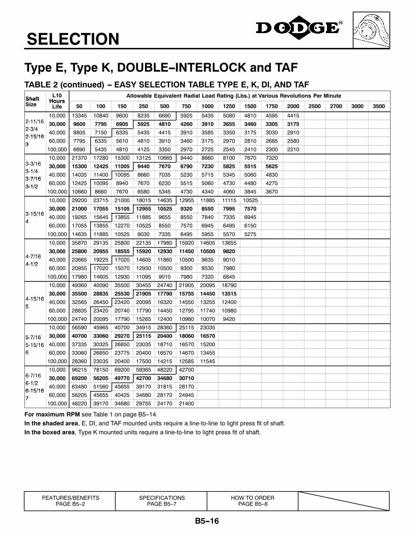
Type E, Type K, DOUBLE--INTERLOCK and TAFTABLE 2 (continued) -- EASY SELECTION TABLE TYPE E, K, DI, AND TAF
Shaft L10Hours
Allowable Equivalent Radial Load Rating (Lbs.) at Various Revolutions Per MinuteShaftSize Hours
Life 50 100 150 250 500 750 1000 1250 1500 1750 2000 2500 2700 3000 3500
2 11/1610,000 13345 10840 9600 8235 6690 5925 5435 5080 4810 4595 4415
2-11/162 3/4
30,000 9600 7795 6905 5925 4810 4260 3910 3655 3460 3305 31752-3/42 15/16
40.000 8805 7150 6335 5435 4415 3910 3585 3350 3175 3030 29102-15/163 60,000 7795 6335 5610 4810 3910 3460 3175 2970 2810 2685 25803
100,000 6690 5435 4810 4125 3350 2970 2725 2545 2410 2300 2210
3 3/1610,000 21370 17280 15300 13125 10665 9440 8660 8100 7670 7320
3-3/163 1/4
30,000 15300 12425 11005 9440 7670 6790 7230 5825 5515 56253-1/43 7/16
40.000 14035 11400 10095 8660 7035 5230 5715 5345 5060 48303-7/163-1/2 60,000 12425 10095 8940 7670 6230 5515 5060 4730 4480 42753-1/2
100,000 10660 8660 7670 6580 5345 4730 4340 4060 3845 3670
10,000 29200 23715 21000 18015 14635 12955 11885 11115 10525
3 15/1630,000 21000 17055 15105 12955 10525 9320 8550 7995 7570
3-15/164
40.000 19265 15645 13855 11885 9655 8550 7840 7335 69454
60,000 17055 13855 12270 10525 8550 7570 6945 6495 6150
100,000 14635 11885 10525 9030 7335 6495 5955 5570 5275
10,000 35870 29135 25800 22135 17980 15920 14605 13655
4 7/1630,000 25800 20955 18555 15920 12930 11450 10500 9820
4-7/164 1/2
40,000 23665 19225 17020 14605 11860 10500 9635 90104-1/2
60,000 20955 17020 15070 12930 10500 9300 8530 7980
100,000 17980 14605 12930 11095 9010 7980 7320 6845
10,000 49360 40090 35500 30455 24740 21905 20095 18790
4 15/1630,000 35500 28835 25530 21905 17790 15755 14450 13515
4-15/165
40,000 32565 26450 23420 20095 16320 14550 13255 124005
60,000 28835 23420 20740 17790 14450 12795 11740 10980
100,000 24740 20095 17790 15265 12400 10980 10070 9420
10,000 56590 45965 40700 34915 28360 25115 23035
5-7/16 30,000 40700 33060 29270 25115 20400 18060 165705 7/165-15/16 40,000 37335 30325 26850 23035 18710 16570 152005 15/166 60,000 33060 26850 23775 20400 16570 14670 13455
100,000 28360 23035 20400 17500 14215 12585 11545
6 7/1610,000 96215 78150 69200 59365 48220 42700
6-7/166 1/2
30,000 69200 56205 49770 42700 34680 307106-1/26 15/16
40.000 63480 51560 45655 39170 31815 281706-15/167 60,000 56205 45655 40425 34680 28170 249457
100,000 48220 39170 34680 29755 24170 21400
For maximum RPM see Table 1 on page B5--14.In the shaded area, E, DI, and TAF mounted units require a line-to-line to light press fit of shaft.In the boxed area, Type K mounted units require a line-to-line to light press fit of shaft.
FEATURES/BENEFITSPAGE B5--2
SPECIFICATIONSPAGE B5--7
HOW TO ORDERPAGE B5--8
B5--17
SELECTION
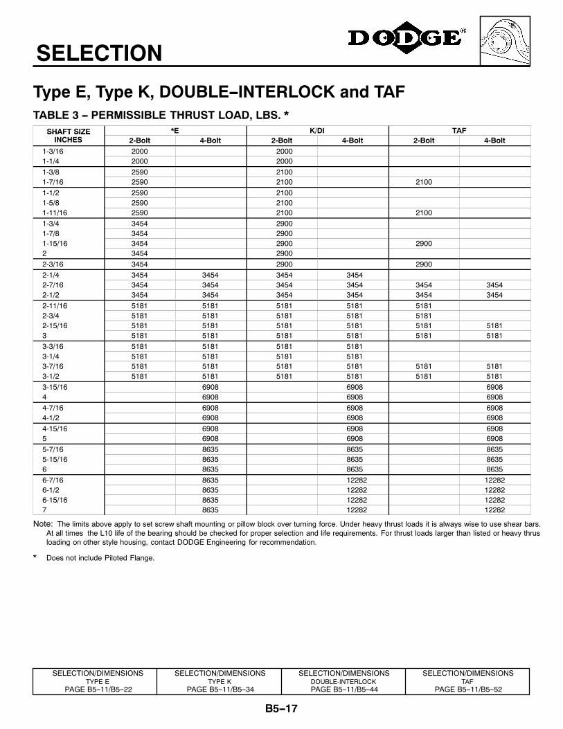
Type E, Type K, DOUBLE--INTERLOCK and TAFTABLE 3 -- PERMISSIBLE THRUST LOAD, LBS. *
SHAFT SIZE *E K/DI TAFSHAFT SIZEINCHES 2-Bolt 4-Bolt 2-Bolt 4-Bolt 2-Bolt 4-Bolt
1-3/16 2000 20001-1/4 2000 20001-3/8 2590 21001-7/16 2590 2100 21001-1/2 2590 21001-5/8 2590 21001-11/16 2590 2100 21001-3/4 3454 29001-7/8 3454 29001-15/16 3454 2900 29002 3454 29002-3/16 3454 2900 29002-1/4 3454 3454 3454 34542-7/16 3454 3454 3454 3454 3454 34542-1/2 3454 3454 3454 3454 3454 34542-11/16 5181 5181 5181 5181 51812-3/4 5181 5181 5181 5181 51812-15/16 5181 5181 5181 5181 5181 51813 5181 5181 5181 5181 5181 51813-3/16 5181 5181 5181 51813-1/4 5181 5181 5181 51813-7/16 5181 5181 5181 5181 5181 51813-1/2 5181 5181 5181 5181 5181 51813-15/16 6908 6908 69084 6908 6908 69084-7/16 6908 6908 69084-1/2 6908 6908 69084-15/16 6908 6908 69085 6908 6908 69085-7/16 8635 8635 86355-15/16 8635 8635 86356 8635 8635 86356-7/16 8635 12282 122826-1/2 8635 12282 122826-15/16 8635 12282 122827 8635 12282 12282
Note: The limits above apply to set screw shaft mounting or pillow block over turning force. Under heavy thrust loads it is always wise to use shear bars.At all times the L10 life of the bearing should be checked for proper selection and life requirements. For thrust loads larger than listed or heavy thrusloading on other style housing, contact DODGE Engineering for recommendation.
* Does not include Piloted Flange.
SELECTION/DIMENSIONSTYPE E
PAGE B5--11/B5--22
SELECTION/DIMENSIONSTYPE K
PAGE B5--11/B5--34
SELECTION/DIMENSIONSDOUBLE-INTERLOCKPAGE B5--11/B5--44
SELECTION/DIMENSIONSTAF
PAGE B5--11/B5--52
B5--18
SELECTION
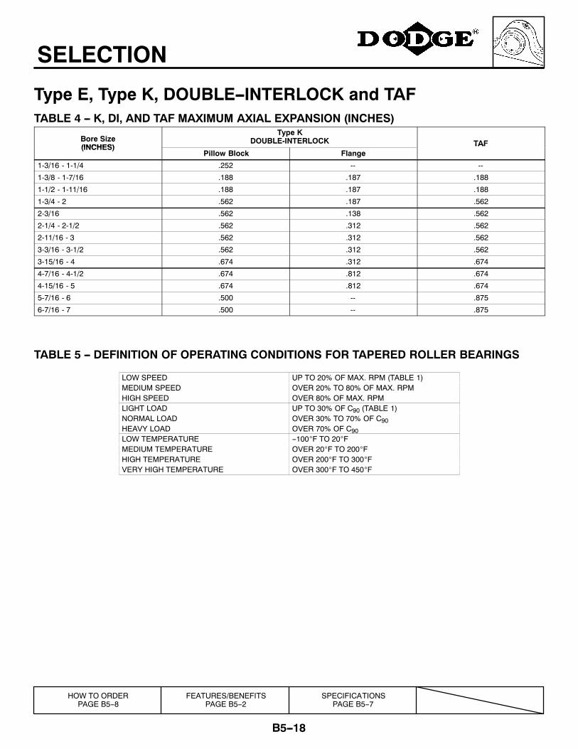
Type E, Type K, DOUBLE--INTERLOCK and TAFTABLE 4 -- K, DI, AND TAF MAXIMUM AXIAL EXPANSION (INCHES)
Bore Size(INCHES)
Type KDOUBLE-INTERLOCK TAF(INCHES)
Pillow Block FlangeTAF
1-3/16 - 1-1/4 .252 -- --
1-3/8 - 1-7/16 .188 .187 .188
1-1/2 - 1-11/16 .188 .187 .188
1-3/4 - 2 .562 .187 .562
2-3/16 .562 .138 .562
2-1/4 - 2-1/2 .562 .312 .562
2-11/16 - 3 .562 .312 .562
3-3/16 - 3-1/2 .562 .312 .562
3-15/16 - 4 .674 .312 .674
4-7/16 - 4-1/2 .674 .812 .674
4-15/16 - 5 .674 .812 .674
5-7/16 - 6 .500 -- .875
6-7/16 - 7 .500 -- .875
TABLE 5 -- DEFINITION OF OPERATING CONDITIONS FOR TAPERED ROLLER BEARINGS
LOW SPEED UP TO 20% OF MAX. RPM (TABLE 1)MEDIUM SPEED OVER 20% TO 80% OF MAX. RPMHIGH SPEED OVER 80% OF MAX. RPMLIGHT LOAD UP TO 30% OF C90 (TABLE 1)NORMAL LOAD OVER 30% TO 70% OF C90HEAVY LOAD OVER 70% OF C90LOW TEMPERATURE --100°F TO 20°FMEDIUM TEMPERATURE OVER 20°F TO 200°FHIGH TEMPERATURE OVER 200°F TO 300°FVERY HIGH TEMPERATURE OVER 300°F TO 450°F
HOW TO ORDERPAGE B5--8
FEATURES/BENEFITSPAGE B5--2
SPECIFICATIONSPAGE B5--7
B5--19
SELECTION
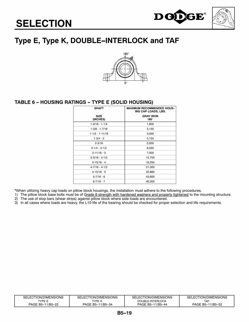
Type E, Type K, DOUBLE--INTERLOCK and TAF
0°
180°
TABLE 6 -- HOUSING RATINGS -- TYPE E (SOLID HOUSING)SHAFT MAXIMUM RECOMMENDED HOUS-
ING CAP LOADS, LBS.
SIZE(INCHES)
GRAY IRON180°
1-3/16 - 1-1/4 1,600
1-3/8 - 1-7/16 3,150
1-1/2 - 1-11/16 3,000
1-3/4 - 2 5,150
2-3/16 3,500
2-1/4 - 2-1/2 6,550
2-11/16 - 3 7,000
3-3/16 - 3-1/2 15,700
3-15/16 - 4 16,250
4-7/16 - 4-1/2 21,000
4-15/16 - 5 22,860
5-7/16 - 6 43,600
6-7/16 - 7 46,000
*When utilizing heavy cap loads on pillow block housings, the installation must adhere to the following procedures.1) The pillow block base bolts must be of Grade 8 strength with hardened washers and properly tightened to the mounting structure.2) The use of stop bars (shear strips) against pillow block where side loads are encountered.3) In all cases where loads are heavy, the L10 life of the bearing should be checked for proper selection and life requirements.
SELECTION/DIMENSIONSTYPE E
PAGE B5--11/B5--22
SELECTION/DIMENSIONSTYPE K
PAGE B5--11/B5--34
SELECTION/DIMENSIONSDOUBLE-INTERLOCKPAGE B5--11/B5--44
SELECTION/DIMENSIONSTAF
PAGE B5--11/B5--52
B5--20
SELECTION
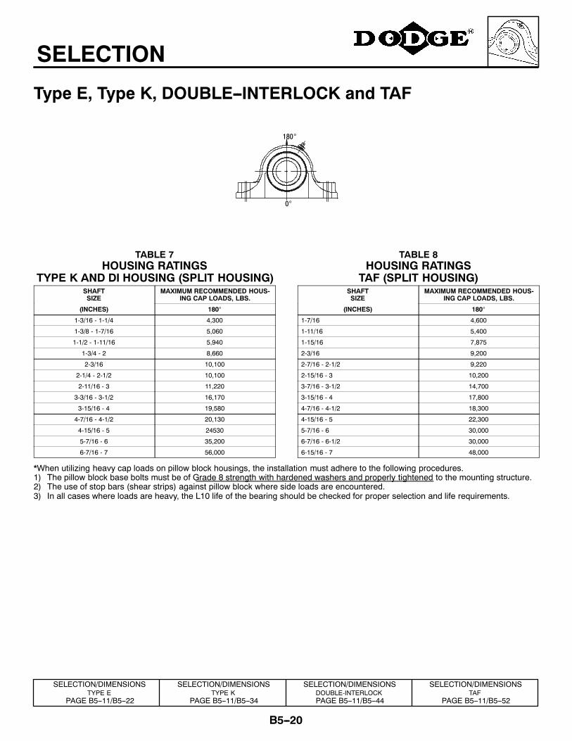
Type E, Type K, DOUBLE--INTERLOCK and TAF
0°
180°
TABLE 7HOUSING RATINGS
TYPE K AND DI HOUSING (SPLIT HOUSING)SHAFTSIZE
MAXIMUM RECOMMENDED HOUS-ING CAP LOADS, LBS.
(INCHES) 180°
1-3/16 - 1-1/4 4,300
1-3/8 - 1-7/16 5,060
1-1/2 - 1-11/16 5,940
1-3/4 - 2 8,660
2-3/16 10,100
2-1/4 - 2-1/2 10,100
2-11/16 - 3 11,220
3-3/16 - 3-1/2 16,170
3-15/16 - 4 19,580
4-7/16 - 4-1/2 20,130
4-15/16 - 5 24530
5-7/16 - 6 35,200
6-7/16 - 7 56,000
TABLE 8HOUSING RATINGS
TAF (SPLIT HOUSING)SHAFTSIZE
MAXIMUM RECOMMENDED HOUS-ING CAP LOADS, LBS.
(INCHES) 180°
1-7/16 4,600
1-11/16 5,400
1-15/16 7,875
2-3/16 9,200
2-7/16 - 2-1/2 9,220
2-15/16 - 3 10,200
3-7/16 - 3-1/2 14,700
3-15/16 - 4 17,800
4-7/16 - 4-1/2 18,300
4-15/16 - 5 22,300
5-7/16 - 6 30,000
6-7/16 - 6-1/2 30,000
6-15/16 - 7 48,000
*When utilizing heavy cap loads on pillow block housings, the installation must adhere to the following procedures.1) The pillow block base bolts must be of Grade 8 strength with hardened washers and properly tightened to the mounting structure.2) The use of stop bars (shear strips) against pillow block where side loads are encountered.3) In all cases where loads are heavy, the L10 life of the bearing should be checked for proper selection and life requirements.
SELECTION/DIMENSIONSTYPE E
PAGE B5--11/B5--22
SELECTION/DIMENSIONSTYPE K
PAGE B5--11/B5--34
SELECTION/DIMENSIONSDOUBLE-INTERLOCKPAGE B5--11/B5--44
SELECTION/DIMENSIONSTAF
PAGE B5--11/B5--52
B5--21
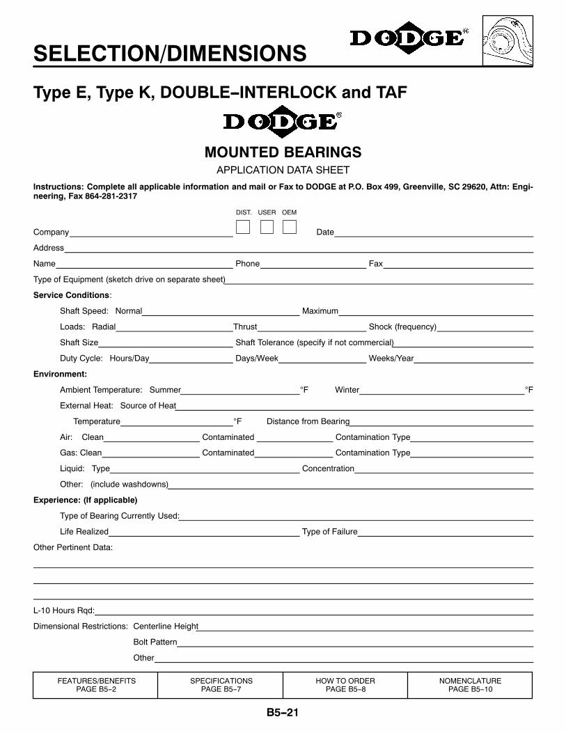
SELECTION/DIMENSIONS
Type E, Type K, DOUBLE--INTERLOCK and TAF
MOUNTED BEARINGSAPPLICATION DATA SHEET
Instructions: Complete all applicable information and mail or Fax to DODGE at P.O. Box 499, Greenville, SC 29620, Attn: Engi-neering, Fax 864-281-2317
Company
DIST. USER OEM
Date
Address
Name Phone Fax
Type of Equipment (sketch drive on separate sheet)
Service Conditions:
Shaft Speed: Normal Maximum
Loads: Radial Thrust Shock (frequency)
Shaft Size Shaft Tolerance (specify if not commercial)
Duty Cycle: Hours/Day Days/Week Weeks/Year
Environment:
Ambient Temperature: Summer °F Winter °F
External Heat: Source of Heat
Temperature °F Distance from Bearing
Air: Clean Contaminated Contamination Type
Gas: Clean Contaminated Contamination Type
Liquid: Type Concentration
Other: (include washdowns)
Experience: (If applicable)
Type of Bearing Currently Used:
Life Realized Type of Failure
Other Pertinent Data:
L-10 Hours Rqd:
Dimensional Restrictions: Centerline Height
Bolt Pattern
Other
FEATURES/BENEFITSPAGE B5--2
SPECIFICATIONSPAGE B5--7
HOW TO ORDERPAGE B5--8
NOMENCLATUREPAGE B5--10
B5--22
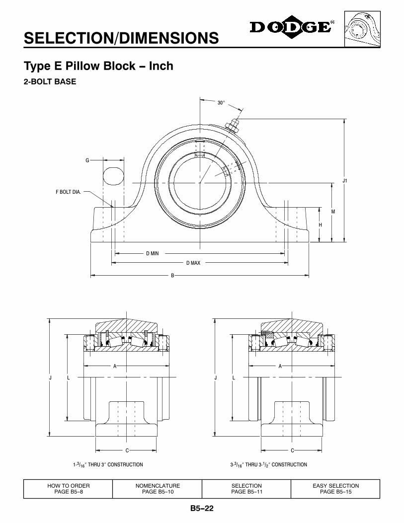
SELECTION/DIMENSIONS
Type E Pillow Block -- Inch2-BOLT BASE
J1
C
LJ
A
H
30°
G
F BOLT DIA.
D MIN
D MAX
B
M
LJ
C
A
3-3/16″ THRU 3-1/2″ CONSTRUCTION1-3/16″ THRU 3″ CONSTRUCTION
HOW TO ORDERPAGE B5--8
NOMENCLATUREPAGE B5--10
SELECTIONPAGE B5--11
EASY SELECTIONPAGE B5--15
B5--23
SELECTION/DIMENSIONS
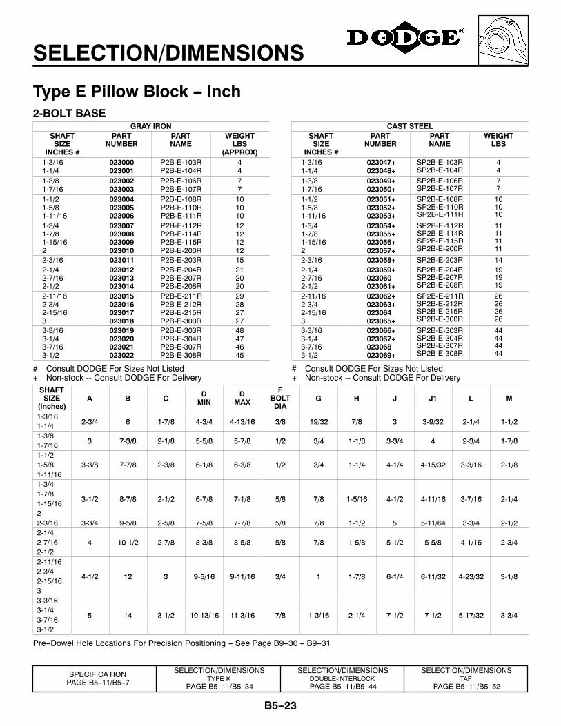
Type E Pillow Block -- Inch2-BOLT BASE
GRAY IRONSHAFTSIZE
INCHES #
PARTNUMBER
PARTNAME
WEIGHTLBS
(APPROX)1-3/161-1/4
023000023001
P2B-E-103RP2B-E-104R
44
1-3/81-7/16
023002023003
P2B-E-106RP2B-E-107R
77
1-1/21-5/81-11/16
023004023005023006
P2B-E-108RP2B-E-110RP2B-E-111R
101010
1-3/41-7/81-15/162
023007023008023009023010
P2B-E-112RP2B-E-114RP2B-E-115RP2B-E-200R
12121212
2-3/16 023011 P2B-E-203R 152-1/42-7/162-1/2
023012023013023014
P2B-E-204RP2B-E-207RP2B-E-208R
212020
2-11/162-3/42-15/163
023015023016023017023018
P2B-E-211RP2B-E-212RP2B-E-215RP2B-E-300R
29282727
3-3/163-1/43-7/163-1/2
023019023020023021023022
P2B-E-303RP2B-E-304RP2B-E-307RP2B-E-308R
48474645
# Consult DODGE For Sizes Not Listed+ Non-stock -- Consult DODGE For Delivery
CAST STEELSHAFTSIZE
INCHES #
PARTNUMBER
PARTNAME
WEIGHTLBS
1-3/161-1/4
023047+023048+
SP2B-E-103RSP2B-E-104R
44
1-3/81-7/16
023049+023050+
SP2B-E-106RSP2B-E-107R
77
1-1/21-5/81-11/16
023051+023052+023053+
SP2B-E-108RSP2B-E-110RSP2B-E-111R
101010
1-3/41-7/81-15/162
023054+023055+023056+023057+
SP2B-E-112RSP2B-E-114RSP2B-E-115RSP2B-E-200R
11111111
2-3/16 023058+ SP2B-E-203R 142-1/42-7/162-1/2
023059+023060023061+
SP2B-E-204RSP2B-E-207RSP2B-E-208R
191919
2-11/162-3/42-15/163
023062+023063+023064023065+
SP2B-E-211RSP2B-E-212RSP2B-E-215RSP2B-E-300R
26262626
3-3/163-1/43-7/163-1/2
023066+023067+023068023069+
SP2B-E-303RSP2B-E-304RSP2B-E-307RSP2B-E-308R
44444444
# Consult DODGE For Sizes Not Listed.+ Non-stock -- Consult DODGE For Delivery
SHAFTSIZE
(Inches)A B C D
MIND
MAX
FBOLTDIA
G H J J1 L M
1-3/162 3/4 6 1 7/8 4 3/4 4 13/16 3/8 19/32 7/8 3 3 9/32 2 1/4 1 1/21-1/4 2-3/4 6 1-7/8 4-3/4 4-13/16 3/8 19/32 7/8 3 3-9/32 2-1/4 1-1/2
1-3/83 7 3/8 2 1/8 5 5/8 5 7/8 1/2 3/4 1 1/8 3 3/4 4 2 3/4 1 7/81-7/16 3 7-3/8 2-1/8 5-5/8 5-7/8 1/2 3/4 1-1/8 3-3/4 4 2-3/4 1-7/8
1-1/21-5/8 3-3/8 7-7/8 2-3/8 6-1/8 6-3/8 1/2 3/4 1-1/4 4-1/4 4-15/32 3-3/16 2-1/81-11/16
3 3/8 7 7/8 2 3/8 6 1/8 6 3/8 1/2 3/4 1 1/4 4 1/4 4 15/32 3 3/16 2 1/8
1-3/41-7/8
3 1/2 8 7/8 2 1/2 6 7/8 7 1/8 5/8 7/8 1 5/16 4 1/2 4 11/16 3 7/16 2 1/41-15/16 3-1/2 8-7/8 2-1/2 6-7/8 7-1/8 5/8 7/8 1-5/16 4-1/2 4-11/16 3-7/16 2-1/4
22-3/16 3-3/4 9-5/8 2-5/8 7-5/8 7-7/8 5/8 7/8 1-1/2 5 5-11/64 3-3/4 2-1/22-1/42-7/16 4 10-1/2 2-7/8 8-3/8 8-5/8 5/8 7/8 1-5/8 5-1/2 5-5/8 4-1/16 2-3/42-1/2
4 10 1/2 2 7/8 8 3/8 8 5/8 5/8 7/8 1 5/8 5 1/2 5 5/8 4 1/16 2 3/4
2-11/162-3/4
4 1/2 12 3 9 5/16 9 11/16 3/4 1 1 7/8 6 1/4 6 11/32 4 23/32 3 1/82-15/16 4-1/2 12 3 9-5/16 9-11/16 3/4 1 1-7/8 6-1/4 6-11/32 4-23/32 3-1/8
33-3/163-1/4
5 14 3 1/2 10 13/16 11 3/16 7/8 1 3/16 2 1/4 7 1/2 7 1/2 5 17/32 3 3/43-7/16 5 14 3-1/2 10-13/16 11-3/16 7/8 1-3/16 2-1/4 7-1/2 7-1/2 5-17/32 3-3/4
3-1/2
Pre--Dowel Hole Locations For Precision Positioning -- See Page B9--30 -- B9--31
SPECIFICATIONPAGE B5--11/B5--7
SELECTION/DIMENSIONSTYPE K
PAGE B5--11/B5--34
SELECTION/DIMENSIONSDOUBLE-INTERLOCKPAGE B5--11/B5--44
SELECTION/DIMENSIONSTAF
PAGE B5--11/B5--52
B5--24
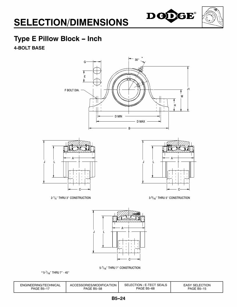
SELECTION/DIMENSIONS
Type E Pillow Block -- Inch4-BOLT BASE
* 5-7/16″ THRU 7″ - 45°
*
J1
A
A A
E
C
L
5-7/16″ THRU 7″ CONSTRUCTION
J
C
J L
H
30°G
F BOLT DIA.
D MIN
D MAX
B
M
LJ
C
3-3/16″ THRU 5″ CONSTRUCTION2-1/4″ THRU 3″ CONSTRUCTION
ENGINEERING/TECHNICALPAGE B5--17
ACCESSORIES/MODIFICATIONPAGE B5--58
EASY SELECTIONPAGE B5--15
SELECTION / E-TECT SEALSPAGE B5--68
B5--25
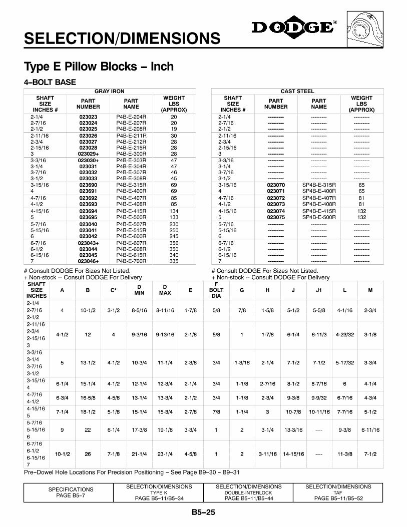
SELECTION/DIMENSIONS
Type E Pillow Blocks -- Inch4--BOLT BASE
GRAY IRONSHAFTSIZE
INCHES #
PARTNUMBER
PARTNAME
WEIGHTLBS
(APPROX)2-1/42-7/162-1/2
023023023024023025
P4B-E-204RP4B-E-207RP4B-E-208R
202019
2-11/162-3/42-15/163
023026023027023028023029+
P4B-E-211RP4B-E-212RP4B-E-215RP4B-E-300R
30282828
3-3/163-1/43-7/163-1/2
023030+023031023032023033
P4B-E-303RP4B-E-304RP4B-E-307RP4B-E-308R
47474645
3-15/164
023690023691
P4B-E-315RP4B-E-400R
6969
4-7/164-1/2
023692023693
P4B-E-407RP4B-E-408R
8585
4-15/165
023694023695
P4B-E-415RP4B-E-500R
134133
5-7/165-15/166
023040023041023042
P4B-E-507RP4B-E-515RP4B-E-600R
230250245
6-7/166-1/26-15/167
023043+023044023045023046+
P4B-E-607RP4B-E-608RP4B-E-615RP4B-E-700R
356350340335
# Consult DODGE For Sizes Not Listed.+ Non-stock -- Consult DODGE For Delivery
CAST STEELSHAFTSIZE
INCHES #
PARTNUMBER
PARTNAME
WEIGHTLBS
(APPROX)2-1/42-7/162-1/2
---------------------------
---------------------------
---------------------------
2-11/162-3/42-15/163
------------------------------------
------------------------------------
------------------------------------
3-3/163-1/43-7/163-1/2
------------------------------------
------------------------------------
------------------------------------
3-15/164
023070023071
SP4B-E-315RSP4B-E-400R
6565
4-7/164-1/2
023072023073
SP4B-E-407RSP4B-E-408R
8181
4-15/165
023074023075
SP4B-E-415RSP4B-E-500R
132132
5-7/165-15/166
---------------------------
---------------------------
---------------------------
6-7/166-1/26-15/167
------------------------------------
------------------------------------
------------------------------------
# Consult DODGE For Sizes Not Listed.+ Non-stock -- Consult DODGE For Delivery
SHAFTSIZE
INCHESA B C* D
MIND
MAX EF
BOLTDIA
G H J J1 L M
2-1/42-7/16 4 10-1/2 3-1/2 8-5/16 8-11/16 1-7/8 5/8 7/8 1-5/8 5-1/2 5-5/8 4-1/16 2-3/42-1/2
4 10 1/2 3 1/2 8 5/16 8 11/16 1 7/8 5/8 7/8 1 5/8 5 1/2 5 5/8 4 1/16 2 3/4
2-11/162-3/4
4-1/2 12 4 9-3/16 9-13/16 2-1/8 5/8 1 1-7/8 6-1/4 6-11/3 4-23/32 3-1/82-15/16
4-1/2 12 4 9-3/16 9-13/16 2-1/8 5/8 1 1-7/8 6-1/4 6-11/3 4-23/32 3-1/8
33-3/163-1/4
5 13-1/2 4-1/2 10-3/4 11-1/4 2-3/8 3/4 1-3/16 2-1/4 7-1/2 7-1/2 5-17/32 3-3/43-7/16
5 13-1/2 4-1/2 10-3/4 11-1/4 2-3/8 3/4 1-3/16 2-1/4 7-1/2 7-1/2 5-17/32 3-3/4
3-1/23-15/16
6-1/4 15-1/4 4-1/2 12-1/4 12-3/4 2-1/4 3/4 1-1/8 2-7/16 8-1/2 8-7/16 6 4-1/44
6-1/4 15-1/4 4-1/2 12-1/4 12-3/4 2-1/4 3/4 1-1/8 2-7/16 8-1/2 8-7/16 6 4-1/4
4-7/166-3/4 16-5/8 4-5/8 13-1/4 13-3/4 2-1/2 3/4 1-1/8 2-3/4 9-3/8 9-9/32 6-7/16 4-3/4
4-1/26-3/4 16-5/8 4-5/8 13-1/4 13-3/4 2-1/2 3/4 1-1/8 2-3/4 9-3/8 9-9/32 6-7/16 4-3/4
4-15/167-1/4 18-1/2 5-1/8 15-1/4 15-3/4 2-7/8 7/8 1-1/4 3 10-7/8 10-11/16 7-7/16 5-1/2
57-1/4 18-1/2 5-1/8 15-1/4 15-3/4 2-7/8 7/8 1-1/4 3 10-7/8 10-11/16 7-7/16 5-1/2
5-7/165-15/16 9 22 6-1/4 17-3/8 19-1/8 3-3/4 1 2 3-1/4 13-3/16 ---- 9-3/8 6-11/166
9 22 6 1/4 17 3/8 19 1/8 3 3/4 1 2 3 1/4 13 3/16 9 3/8 6 11/16
6-7/166-1/2
10-1/2 26 7-1/8 21-1/4 23-1/4 4-5/8 1 2 3-11/16 14-15/16 ---- 11-3/8 7-1/26-15/16
10-1/2 26 7-1/8 21-1/4 23-1/4 4-5/8 1 2 3-11/16 14-15/16 ---- 11-3/8 7-1/2
7Pre--Dowel Hole Locations For Precision Positioning -- See Page B9--30 -- B9--31
SPECIFICATIONSPAGE B5--7
SELECTION/DIMENSIONSTYPE K
PAGE B5--11/B5--34
SELECTION/DIMENSIONSDOUBLE-INTERLOCKPAGE B5--11/B5--44
SELECTION/DIMENSIONSTAF
PAGE B5--11/B5--52
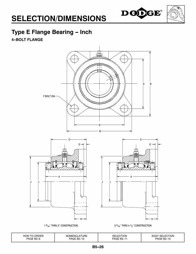
B5--26
SELECTION/DIMENSIONS
Type E Flange Bearing -- Inch4--BOLT FLANGE
H
E
C
H
C
E
LJ
AA
F BOLT DIA.
B
D
D B
LJ
3-3/16″ THRU 4-1/2″ CONSTRUCTION1-3/16″ THRU 3″ CONSTRUCTION
HOW TO ORDERPAGE B5--8
NOMENCLATUREPAGE B5--10
SELECTIONPAGE B5--11
EASY SELECTIONPAGE B5--15
B5--27
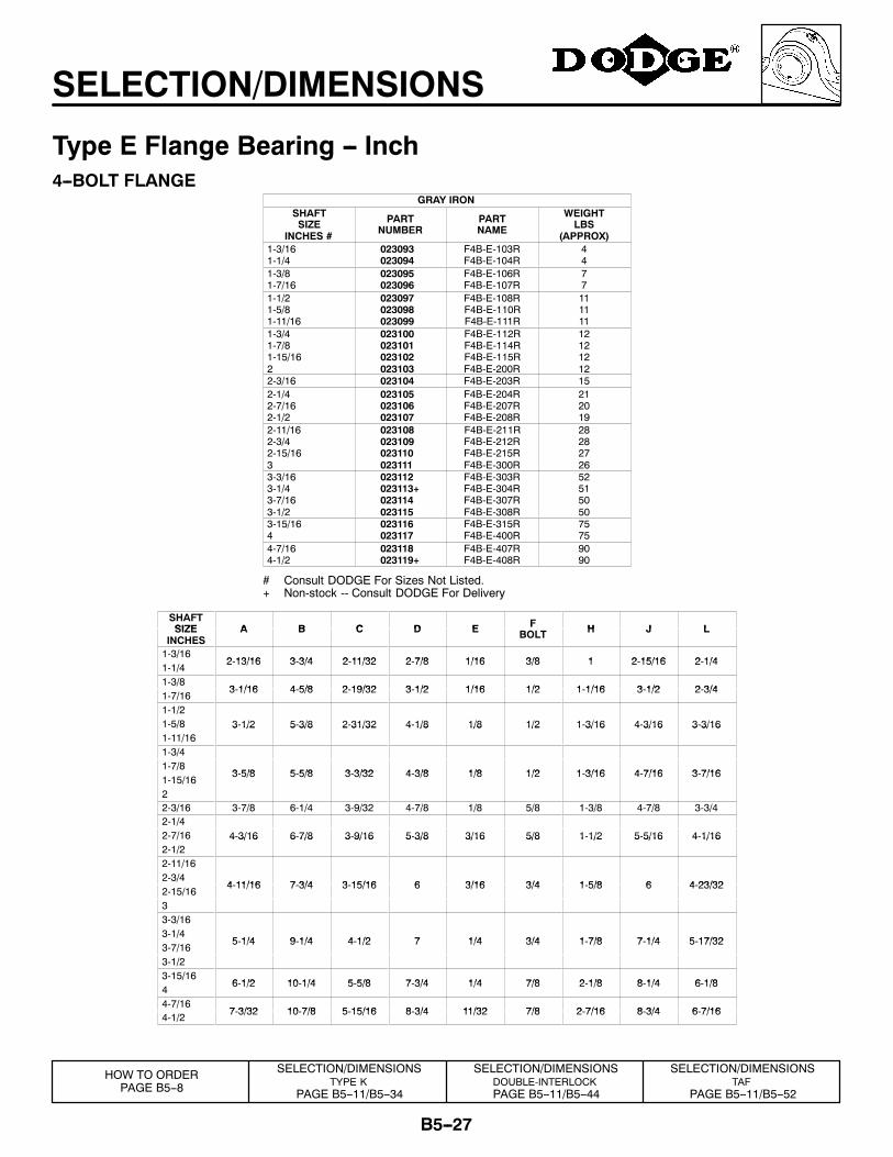
SELECTION/DIMENSIONS
Type E Flange Bearing -- Inch4--BOLT FLANGE
GRAY IRONSHAFTSIZE
INCHES #
PARTNUMBER
PARTNAME
WEIGHTLBS
(APPROX)1-3/161-1/4
023093023094
F4B-E-103RF4B-E-104R
44
1-3/81-7/16
023095023096
F4B-E-106RF4B-E-107R
77
1-1/21-5/81-11/16
023097023098023099
F4B-E-108RF4B-E-110RF4B-E-111R
111111
1-3/41-7/81-15/162
023100023101023102023103
F4B-E-112RF4B-E-114RF4B-E-115RF4B-E-200R
12121212
2-3/16 023104 F4B-E-203R 152-1/42-7/162-1/2
023105023106023107
F4B-E-204RF4B-E-207RF4B-E-208R
212019
2-11/162-3/42-15/163
023108023109023110023111
F4B-E-211RF4B-E-212RF4B-E-215RF4B-E-300R
28282726
3-3/163-1/43-7/163-1/2
023112023113+023114023115
F4B-E-303RF4B-E-304RF4B-E-307RF4B-E-308R
52515050
3-15/164
023116023117
F4B-E-315RF4B-E-400R
7575
4-7/164-1/2
023118023119+
F4B-E-407RF4B-E-408R
9090
# Consult DODGE For Sizes Not Listed.+ Non-stock -- Consult DODGE For Delivery
SHAFTSIZE A B C D E F H J LSIZE
INCHESA B C D E F
BOLT H J L
1-3/162 13/16 3 3/4 2 11/32 2 7/8 1/16 3/8 1 2 15/16 2 1/4
1-1/42-13/16 3-3/4 2-11/32 2-7/8 1/16 3/8 1 2-15/16 2-1/4
1-3/83 1/16 4 5/8 2 19/32 3 1/2 1/16 1/2 1 1/16 3 1/2 2 3/4
1-7/163-1/16 4-5/8 2-19/32 3-1/2 1/16 1/2 1-1/16 3-1/2 2-3/4
1-1/21-5/8 3-1/2 5-3/8 2-31/32 4-1/8 1/8 1/2 1-3/16 4-3/16 3-3/161-11/16
3 1/2 5 3/8 2 31/32 4 1/8 1/8 1/2 1 3/16 4 3/16 3 3/16
1-3/41-7/8
3 5/8 5 5/8 3 3/32 4 3/8 1/8 1/2 1 3/16 4 7/16 3 7/161-15/16
3-5/8 5-5/8 3-3/32 4-3/8 1/8 1/2 1-3/16 4-7/16 3-7/16
22-3/16 3-7/8 6-1/4 3-9/32 4-7/8 1/8 5/8 1-3/8 4-7/8 3-3/42-1/42-7/16 4-3/16 6-7/8 3-9/16 5-3/8 3/16 5/8 1-1/2 5-5/16 4-1/162-1/2
4 3/16 6 7/8 3 9/16 5 3/8 3/16 5/8 1 1/2 5 5/16 4 1/16
2-11/162-3/4
4 11/16 7 3/4 3 15/16 6 3/16 3/4 1 5/8 6 4 23/322-15/16
4-11/16 7-3/4 3-15/16 6 3/16 3/4 1-5/8 6 4-23/32
33-3/163-1/4
5 1/4 9 1/4 4 1/2 7 1/4 3/4 1 7/8 7 1/4 5 17/323-7/16
5-1/4 9-1/4 4-1/2 7 1/4 3/4 1-7/8 7-1/4 5-17/32
3-1/23-15/16
6 1/2 10 1/4 5 5/8 7 3/4 1/4 7/8 2 1/8 8 1/4 6 1/84
6-1/2 10-1/4 5-5/8 7-3/4 1/4 7/8 2-1/8 8-1/4 6-1/8
4-7/167 3/32 10 7/8 5 15/16 8 3/4 11/32 7/8 2 7/16 8 3/4 6 7/16
4-1/27-3/32 10-7/8 5-15/16 8-3/4 11/32 7/8 2-7/16 8-3/4 6-7/16
SELECTION/DIMENSIONSTYPE K
PAGE B5--11/B5--34
SELECTION/DIMENSIONSDOUBLE-INTERLOCKPAGE B5--11/B5--44
SELECTION/DIMENSIONSTAF
PAGE B5--11/B5--52
HOW TO ORDERPAGE B5--8
B5--28
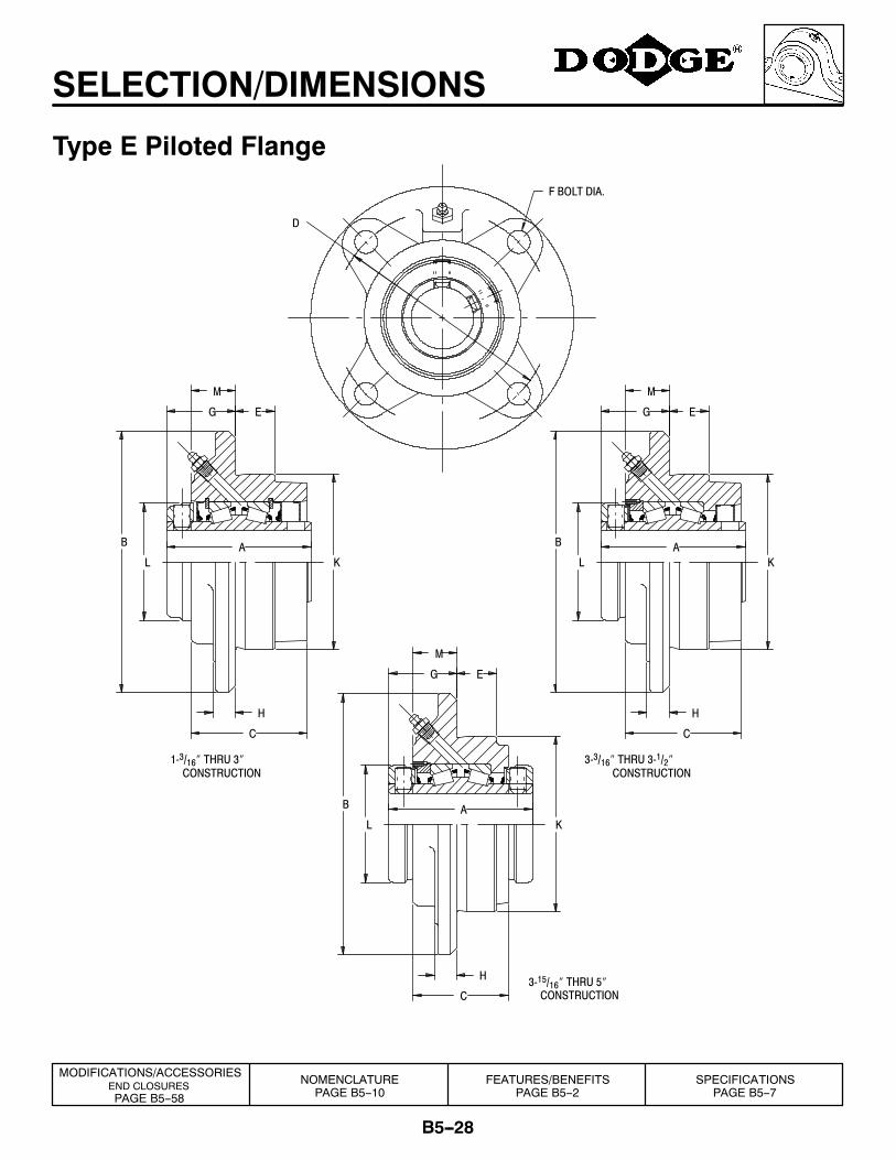
SELECTION/DIMENSIONS
Type E Piloted Flange
G
L
M
G
MM
H
H
F BOLT DIA.
D
CONSTRUCTION3-15/16″ THRU 5″
CONSTRUCTION3-3/16″ THRU 3-1/2″
CONSTRUCTION1-3/16″ THRU 3″
AK
C
B
E
AK
C
L
B
E
H
C
K
EG
L
B A
FEATURES/BENEFITSPAGE B5--2
SPECIFICATIONSPAGE B5--7
MODIFICATIONS/ACCESSORIESEND CLOSURESPAGE B5--58
NOMENCLATUREPAGE B5--10
B5--29
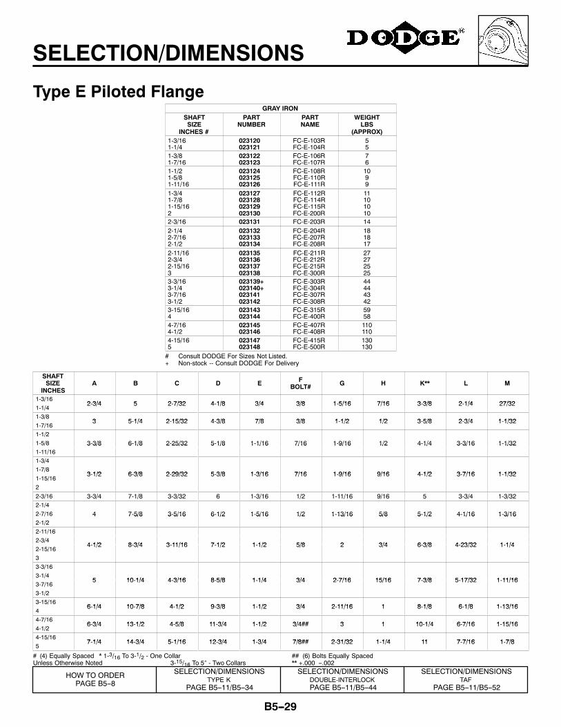
SELECTION/DIMENSIONS
Type E Piloted FlangeGRAY IRON
SHAFTSIZE
INCHES #
PARTNUMBER
PARTNAME
WEIGHTLBS
(APPROX)1-3/161-1/4
023120023121
FC-E-103RFC-E-104R
55
1-3/81-7/16
023122023123
FC-E-106RFC-E-107R
76
1-1/21-5/81-11/16
023124023125023126
FC-E-108RFC-E-110RFC-E-111R
1099
1-3/41-7/81-15/162
023127023128023129023130
FC-E-112RFC-E-114RFC-E-115RFC-E-200R
11101010
2-3/16 023131 FC-E-203R 142-1/42-7/162-1/2
023132023133023134
FC-E-204RFC-E-207RFC-E-208R
181817
2-11/162-3/42-15/163
023135023136023137023138
FC-E-211RFC-E-212RFC-E-215RFC-E-300R
27272525
3-3/163-1/43-7/163-1/2
023139+023140+023141023142
FC-E-303RFC-E-304RFC-E-307RFC-E-308R
44444342
3-15/164
023143023144
FC-E-315RFC-E-400R
5958
4-7/164-1/2
023145023146
FC-E-407RFC-E-408R
110110
4-15/165
023147023148
FC-E-415RFC-E-500R
130130
# Consult DODGE For Sizes Not Listed.+ Non-stock -- Consult DODGE For Delivery
SHAFTSIZE
INCHESA B C D E F
BOLT# G H K** L M
1-3/162 3/4 5 2 7/32 4 1/8 3/4 3/8 1 5/16 7/16 3 3/8 2 1/4 27/32
1-1/42-3/4 5 2-7/32 4-1/8 3/4 3/8 1-5/16 7/16 3-3/8 2-1/4 27/32
1-3/83 5 1/4 2 15/32 4 3/8 7/8 3/8 1 1/2 1/2 3 5/8 2 3/4 1 1/32
1-7/163 5-1/4 2-15/32 4-3/8 7/8 3/8 1-1/2 1/2 3-5/8 2-3/4 1-1/32
1-1/21-5/8 3-3/8 6-1/8 2-25/32 5-1/8 1-1/16 7/16 1-9/16 1/2 4-1/4 3-3/16 1-1/321-11/16
3 3/8 6 1/8 2 25/32 5 1/8 1 1/16 7/16 1 9/16 1/2 4 1/4 3 3/16 1 1/32
1-3/41-7/8
3 1/2 6 3/8 2 29/32 5 3/8 1 3/16 7/16 1 9/16 9/16 4 1/2 3 7/16 1 1/321-15/16
3-1/2 6-3/8 2-29/32 5-3/8 1-3/16 7/16 1-9/16 9/16 4-1/2 3-7/16 1-1/32
2
2-3/16 3-3/4 7-1/8 3-3/32 6 1-3/16 1/2 1-11/16 9/16 5 3-3/4 1-3/322-1/42-7/16 4 7-5/8 3-5/16 6-1/2 1-5/16 1/2 1-13/16 5/8 5-1/2 4-1/16 1-3/162-1/2
4 7 5/8 3 5/16 6 1/2 1 5/16 1/2 1 13/16 5/8 5 1/2 4 1/16 1 3/16
2-11/162-3/4
4 1/2 8 3/4 3 11/16 7 1/2 1 1/2 5/8 2 3/4 6 3/8 4 23/32 1 1/42-15/16
4-1/2 8-3/4 3-11/16 7-1/2 1-1/2 5/8 2 3/4 6-3/8 4-23/32 1-1/4
33-3/163-1/4
5 10 1/4 4 3/16 8 5/8 1 1/4 3/4 2 7/16 15/16 7 3/8 5 17/32 1 11/163-7/16
5 10-1/4 4-3/16 8-5/8 1-1/4 3/4 2-7/16 15/16 7-3/8 5-17/32 1-11/16
3-1/23-15/16
6 1/4 10 7/8 4 1/2 9 3/8 1 1/2 3/4 2 11/16 1 8 1/8 6 1/8 1 13/164
6-1/4 10-7/8 4-1/2 9-3/8 1-1/2 3/4 2-11/16 1 8-1/8 6-1/8 1-13/16
4-7/166 3/4 13 1/2 4 5/8 11 3/4 1 1/2 3/4## 3 1 10 1/4 6 7/16 1 15/16
4-1/26-3/4 13-1/2 4-5/8 11-3/4 1-1/2 3/4## 3 1 10-1/4 6-7/16 1-15/16
4-15/167 1/4 14 3/4 5 1/16 12 3/4 1 3/4 7/8## 2 31/32 1 1/4 11 7 7/16 1 7/8
57-1/4 14-3/4 5-1/16 12-3/4 1-3/4 7/8## 2-31/32 1-1/4 11 7-7/16 1-7/8
# (4) Equally Spaced * 1-3/16 To 3-1/2 - One CollarUnless Otherwise Noted 3-15/16 To 5″ - Two Collars
## (6) Bolts Equally Spaced** +.000 --.002
SELECTION/DIMENSIONSTYPE K
PAGE B5--11/B5--34
SELECTION/DIMENSIONSDOUBLE-INTERLOCKPAGE B5--11/B5--44
SELECTION/DIMENSIONSTAF
PAGE B5--11/B5--52
HOW TO ORDERPAGE B5--8
B5--30
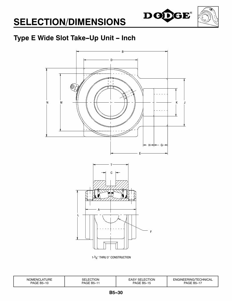
SELECTION/DIMENSIONS
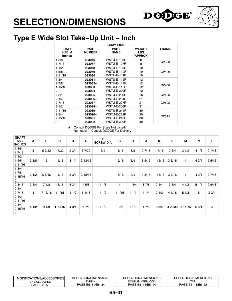
Type E Wide Slot Take--Up Unit -- Inch
JK
G
E
H
B
D
M
T
C
N
L
A
1-3/8″ THRU 3″ CONSTRUCTION
F
NOMENCLATUREPAGE B5--10
SELECTIONPAGE B5--11
EASY SELECTIONPAGE B5--15
ENGINEERING/TECHNICALPAGE B5--17
B5--31
SELECTION/DIMENSIONS
Type E Wide Slot Take--Up Unit -- InchGRAY IRON
SHAFTSIZE #Inches
PARTNUMBER
PARTNAME
WEIGHTLBS
(APPROX)
FRAME
1-3/81-7/16
023076+023077
WSTU-E-106RWSTU-E-107R
88 CP308
1-1/21-5/81-11/16
023078023079+023080
WSTU-E-108RWSTU-E-110RWSTU-E-111R
101010
CP400
1-3/41-7/81-15/162
023081+023082+023083023084
WSTU-E-112RWSTU-E-114RWSTU-E-115RWSTU-E-200R
12121212
CP400
2-3/16 023085 WSTU-E-203R 16 CP4082-1/42-7/162-1/2
023086+023087023088+
WSTU-E-204RWSTU-E-207RWSTU-E-208R
212121
CP502
2-11/162-3/42-15/163
023089+023090+023091023092+
WSTU-E-211RWSTU-E-212RWSTU-E-215RWSTU-E-300R
30303030
CP515
# Consult DODGE For Sizes Not Listed.+ Non-stock -- Consult DODGE For Delivery
SHAFTSIZE
INCHESA B C D E F
SCREW DIA G H J K L M N T
1-3/83 5 3/32 17/32 2 3/4 3 7/32 3/4 11/16 5/8 2 7/16 1 7/16 2 3/4 3 1/2 4 1/8 2 1/161-7/16 3 5-3/32 17/32 2-3/4 3-7/32 3/4 11/16 5/8 2-7/16 1-7/16 2-3/4 3-1/2 4-1/8 2-1/16
1-1/21-5/8 3-3/8 6 11/16 3-1/4 3-13/16 1 15/16 3/4 3-5/16 1-15/16 3-3/16 4 4-3/4 2-5/161-11/16
3 3/8 6 11/16 3 1/4 3 13/16 1 15/16 3/4 3 5/16 1 15/16 3 3/16 4 4 3/4 2 5/16
1-3/41-7/8
3 1/2 6 5/16 11/16 3 3/4 3 15/16 1 15/16 3/4 3 5/16 1 15/16 3 7/16 4 4 3/4 2 7/161-15/16 3-1/2 6-5/16 11/16 3-3/4 3-15/16 1 15/16 3/4 3-5/16 1-15/16 3-7/16 4 4-3/4 2-7/16
22-3/16 3-3/4 7-1/8 13/16 3-3/4 4-5/8 1-1/8 1 1--1/4 3-7/8 2-1/4 3-3/4 4-1/2 5-1/4 2-9/162-1/42-7/16 4 7-13/16 1-1/16 4-1/2 5-1/16 1-1/2 1-1/16 1-1/4 4-1/4 2-1/2 4-1/16 5-1/8 6 2-3/42-1/2
4 7 13/16 1 1/16 4 1/2 5 1/16 1 1/2 1 1/16 1 1/4 4 1/4 2 1/2 4 1/16 5 1/8 6 2 3/4
2-11/162-3/4
4 1/2 9 1/8 1 13/16 4 3/4 5 7/8 1 1/2 1 3/8 1 1/2 4 7/8 2 3/4 4 23/32 5 15/16 6 3/4 32-15/16 4-1/2 9-1/8 1-13/16 4-3/4 5-7/8 1-1/2 1-3/8 1-1/2 4-7/8 2-3/4 4-23/32 5-15/16 6-3/4 3
3
SELECTION/DIMENSIONSTYPE K
PAGE B5--11/B5--34
SELECTION/DIMENSIONSDOUBLE-INTERLOCKPAGE B5--11/B5--44
SELECTION/DIMENSIONSTAF
PAGE B5--11/B5--52
MODIFICATIONS/ACCESSORIESEND CLOSURESPAGE B5--58
B5--32
SELECTION/DIMENSIONS
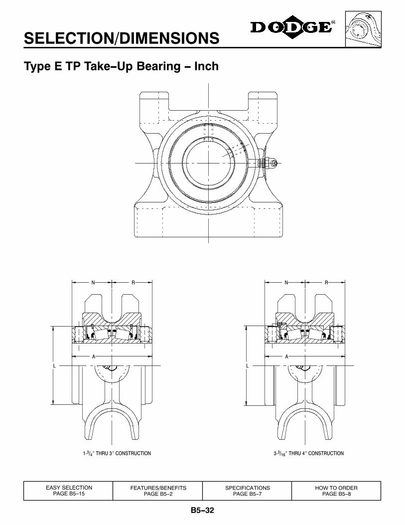
Type E TP Take--Up Bearing -- Inch
RNRN
AA
LL
3-3/16″ THRU 4″ CONSTRUCTION1-3/4″ THRU 3″ CONSTRUCTION
EASY SELECTIONPAGE B5--15
FEATURES/BENEFITSPAGE B5--2
SPECIFICATIONSPAGE B5--7
HOW TO ORDERPAGE B5--8
B5--33
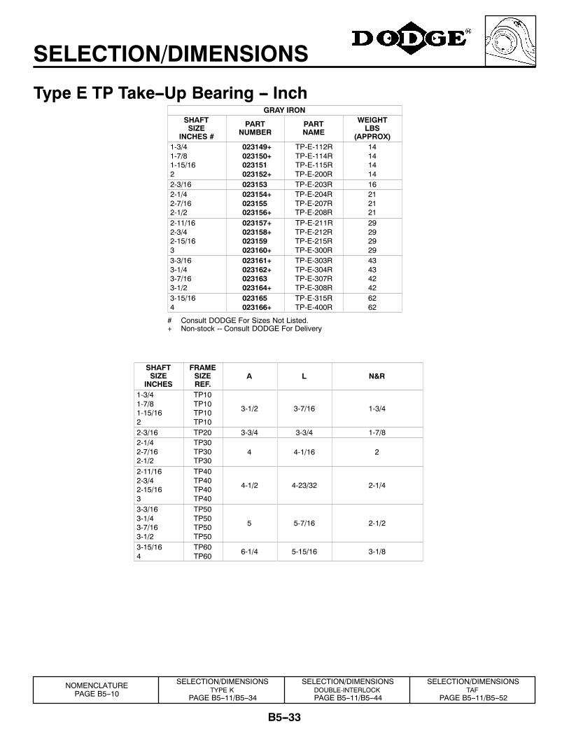
SELECTION/DIMENSIONS
Type E TP Take--Up Bearing -- InchGRAY IRON
SHAFTSIZE
INCHES #
PARTNUMBER
PARTNAME
WEIGHTLBS
(APPROX)1-3/41-7/81-15/162
023149+023150+023151023152+
TP-E-112RTP-E-114RTP-E-115RTP-E-200R
14141414
2-3/16 023153 TP-E-203R 162-1/42-7/162-1/2
023154+023155023156+
TP-E-204RTP-E-207RTP-E-208R
212121
2-11/162-3/42-15/163
023157+023158+023159023160+
TP-E-211RTP-E-212RTP-E-215RTP-E-300R
29292929
3-3/163-1/43-7/163-1/2
023161+023162+023163023164+
TP-E-303RTP-E-304RTP-E-307RTP-E-308R
43434242
3-15/164
023165023166+
TP-E-315RTP-E-400R
6262
# Consult DODGE For Sizes Not Listed.+ Non-stock -- Consult DODGE For Delivery
SHAFTSIZE
INCHES
FRAMESIZEREF.
A L N&R
1-3/41-7/81-15/162
TP10TP10TP10TP10
3-1/2 3-7/16 1-3/4
2-3/16 TP20 3-3/4 3-3/4 1-7/82-1/42-7/162-1/2
TP30TP30TP30
4 4-1/16 2
2-11/162-3/42-15/163
TP40TP40TP40TP40
4-1/2 4-23/32 2-1/4
3-3/163-1/43-7/163-1/2
TP50TP50TP50TP50
5 5-7/16 2-1/2
3-15/164
TP60TP60
6-1/4 5-15/16 3-1/8
SELECTION/DIMENSIONSTYPE K
PAGE B5--11/B5--34
SELECTION/DIMENSIONSDOUBLE-INTERLOCKPAGE B5--11/B5--44
SELECTION/DIMENSIONSTAF
PAGE B5--11/B5--52
NOMENCLATUREPAGE B5--10
B5--34
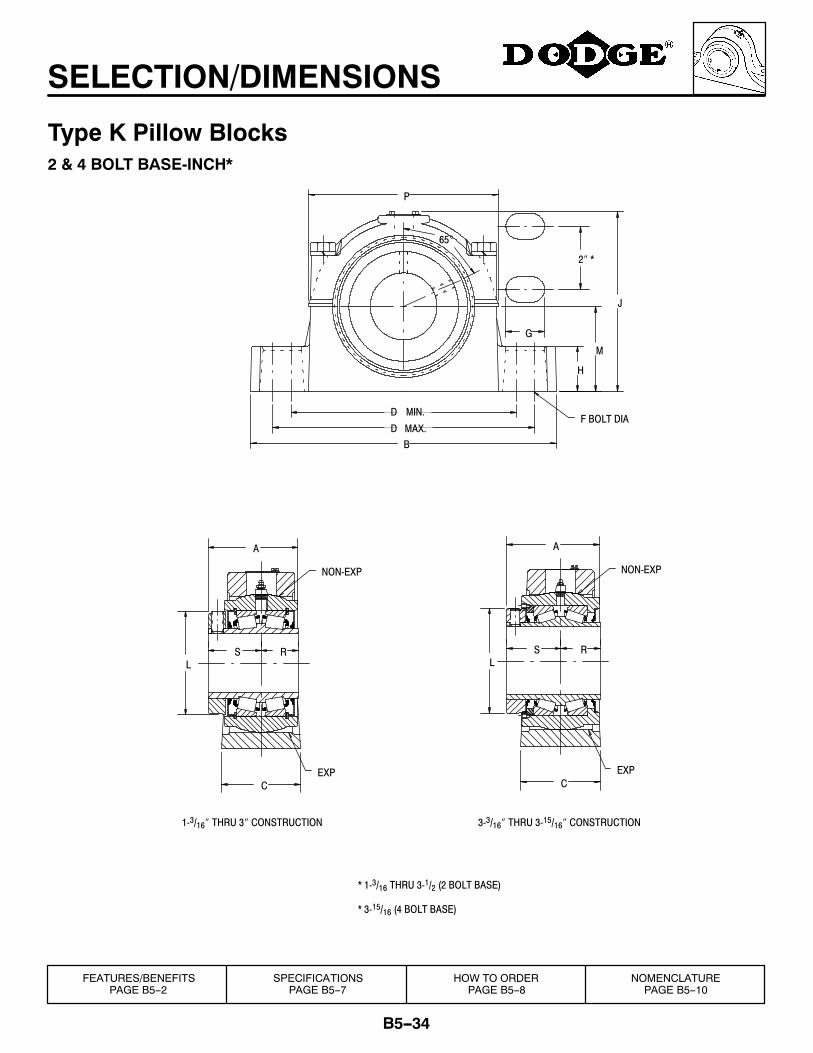
SELECTION/DIMENSIONS
Type K Pillow Blocks2 & 4 BOLT BASE-INCH*
NON-EXP
EXP
SL
NON-EXP
A
EXP
S R
* 3-15/16 (4 BOLT BASE)
C
L
1-3/16″ THRU 3″ CONSTRUCTION
C
3-3/16″ THRU 3-15/16″ CONSTRUCTION
* 1-3/16 THRU 3-1/2 (2 BOLT BASE)
R
A
2″ *
P
J
G
H
M
F BOLT DIAMAX.
MIN.
65°
D
DB
FEATURES/BENEFITSPAGE B5--2
SPECIFICATIONSPAGE B5--7
HOW TO ORDERPAGE B5--8
NOMENCLATUREPAGE B5--10
B5--35
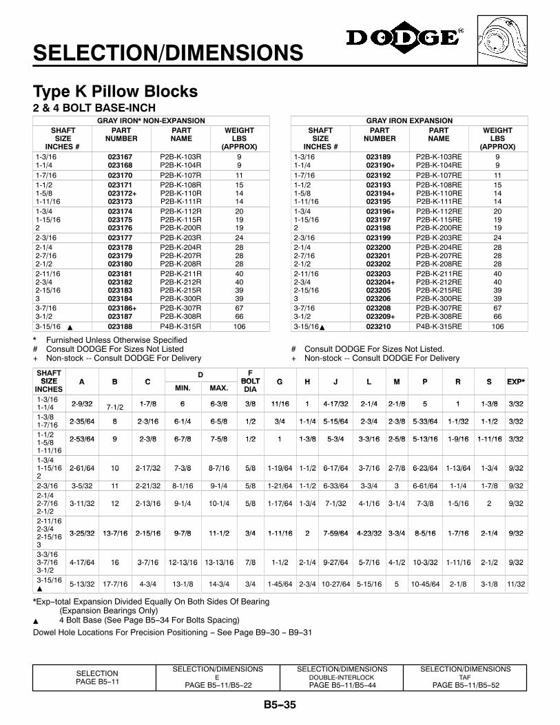
SELECTION/DIMENSIONS
Type K Pillow Blocks2 & 4 BOLT BASE-INCH
GRAY IRON* NON-EXPANSIONSHAFTSIZE
INCHES #
PARTNUMBER
PARTNAME
WEIGHTLBS
(APPROX)1-3/161-1/4
023167023168
P2B-K-103RP2B-K-104R
99
1-7/16 023170 P2B-K-107R 111-1/21-5/81-11/16
023171023172+023173
P2B-K-108RP2B-K-110RP2B-K-111R
151414
1-3/41-15/162
023174023175023176
P2B-K-112RP2B-K-115RP2B-K-200R
201919
2-3/16 023177 P2B-K-203R 242-1/42-7/162-1/2
023178023179023180
P2B-K-204RP2B-K-207RP2B-K-208R
282828
2-11/162-3/42-15/163
023181023182023183023184
P2B-K-211RP2B-K-212RP2B-K-215RP2B-K-300R
40403939
3-7/163-1/2
023186+023187
P2B-K-307RP2B-K-308R
6766
3-15/16 Y 023188 P4B-K-315R 106
* Furnished Unless Otherwise Specified# Consult DODGE For Sizes Not Listed+ Non-stock -- Consult DODGE For Delivery
GRAY IRON EXPANSIONSHAFTSIZE
INCHES #
PARTNUMBER
PARTNAME
WEIGHTLBS
(APPROX)1-3/161-1/4
023189023190+
P2B-K-103REP2B-K-104RE
99
1-7/16 023192 P2B-K-107RE 111-1/21-5/81-11/16
023193023194+023195
P2B-K-108REP2B-K-110REP2B-K-111RE
151414
1-3/41-15/162
023196+023197023198
P2B-K-112REP2B-K-115REP2B-K-200RE
201919
2-3/16 023199 P2B-K-203RE 242-1/42-7/162-1/2
023200023201023202
P2B-K-204REP2B-K-207REP2B-K-208RE
282828
2-11/162-3/42-15/163
023203023204+023205023206
P2B-K-211REP2B-K-212REP2B-K-215REP2B-K-300RE
40403939
3-7/163-1/2
023208023209+
P2B-K-307REP2B-K-308RE
6766
3-15/16Y 023210 P4B-K-315RE 106
# Consult DODGE For Sizes Not Listed.+ Non-stock -- Consult DODGE For Delivery
SHAFTSIZE A B C
D FBOLT G H J L M P R S EXP*SIZE
INCHESA B C
MIN. MAX.BOLTDIA
G H J L M P R S EXP*
1-3/16 2-9/32 1-7/8 6 6-3/8 3/8 11/16 1 4-17/32 2-1/4 2-1/8 5 1 1-3/8 3/321-1/4 2-9/32 7-1/2 1-7/8 6 6-3/8 3/8 11/16 1 4-17/32 2-1/4 2-1/8 5 1 1-3/8 3/32
1-3/8 2-35/64 8 2-3/16 6-1/4 6-5/8 1/2 3/4 1-1/4 5-15/64 2-3/4 2-3/8 5-33/64 1-1/32 1-1/2 3/321-7/16 2-35/64 8 2-3/16 6-1/4 6-5/8 1/2 3/4 1-1/4 5-15/64 2-3/4 2-3/8 5-33/64 1-1/32 1-1/2 3/32
1-1/2 2-53/64 9 2-3/8 6-7/8 7-5/8 1/2 1 1-3/8 5-3/4 3-3/16 2-5/8 5-13/16 1-9/16 1-11/16 3/321-5/8 2-53/64 9 2-3/8 6-7/8 7-5/8 1/2 1 1-3/8 5-3/4 3-3/16 2-5/8 5-13/16 1-9/16 1-11/16 3/32
1-11/161-3/41-15/16 2-61/64 10 2-17/32 7-3/8 8-7/16 5/8 1-19/64 1-1/2 6-17/64 3-7/16 2-7/8 6-23/64 1-13/64 1-3/4 9/322
2 61/64 10 2 17/32 7 3/8 8 7/16 5/8 1 19/64 1 1/2 6 17/64 3 7/16 2 7/8 6 23/64 1 13/64 1 3/4 9/32
2-3/16 3-5/32 11 2-21/32 8-1/16 9-1/4 5/8 1-21/64 1-1/2 6-33/64 3-3/4 3 6-61/64 1-1/4 1-7/8 9/322-1/42-7/16 3-11/32 12 2-13/16 9-1/4 10-1/4 5/8 1-17/64 1-3/4 7-1/32 4-1/16 3-1/4 7-3/8 1-5/16 2 9/322-1/2
3 11/32 12 2 13/16 9 1/4 10 1/4 5/8 1 17/64 1 3/4 7 1/32 4 1/16 3 1/4 7 3/8 1 5/16 2 9/32
2-11/162-3/4 3-25/32 13-7/16 2-15/16 9-7/8 11-1/2 3/4 1-11/16 2 7-59/64 4-23/32 3-3/4 8-5/16 1-7/16 2-1/4 9/322-15/16 3-25/32 13-7/16 2-15/16 9-7/8 11-1/2 3/4 1-11/16 2 7-59/64 4-23/32 3-3/4 8-5/16 1-7/16 2-1/4 9/32
33-3/163-7/16 4-17/64 16 3-7/16 12-13/16 13-13/16 7/8 1-1/2 2-1/4 9-27/64 5-7/16 4-1/2 10-3/32 1-11/16 2-1/2 9/323-1/2
4 17/64 16 3 7/16 12 13/16 13 13/16 7/8 1 1/2 2 1/4 9 27/64 5 7/16 4 1/2 10 3/32 1 11/16 2 1/2 9/32
3-15/16Y
5-13/32 17-7/16 4-3/4 13-1/8 14-3/4 3/4 1-45/64 2-3/4 10-27/64 5-15/16 5 10-45/64 2-1/8 3-1/8 11/32
*Exp--total Expansion Divided Equally On Both Sides Of Bearing(Expansion Bearings Only)
Y 4 Bolt Base (See Page B5--34 For Bolts Spacing)Dowel Hole Locations For Precision Positioning -- See Page B9--30 -- B9--31
SELECTION/DIMENSIONSE
PAGE B5--11/B5--22
SELECTION/DIMENSIONSDOUBLE-INTERLOCKPAGE B5--11/B5--44
SELECTION/DIMENSIONSTAF
PAGE B5--11/B5--52
SELECTIONPAGE B5--11
B5--36
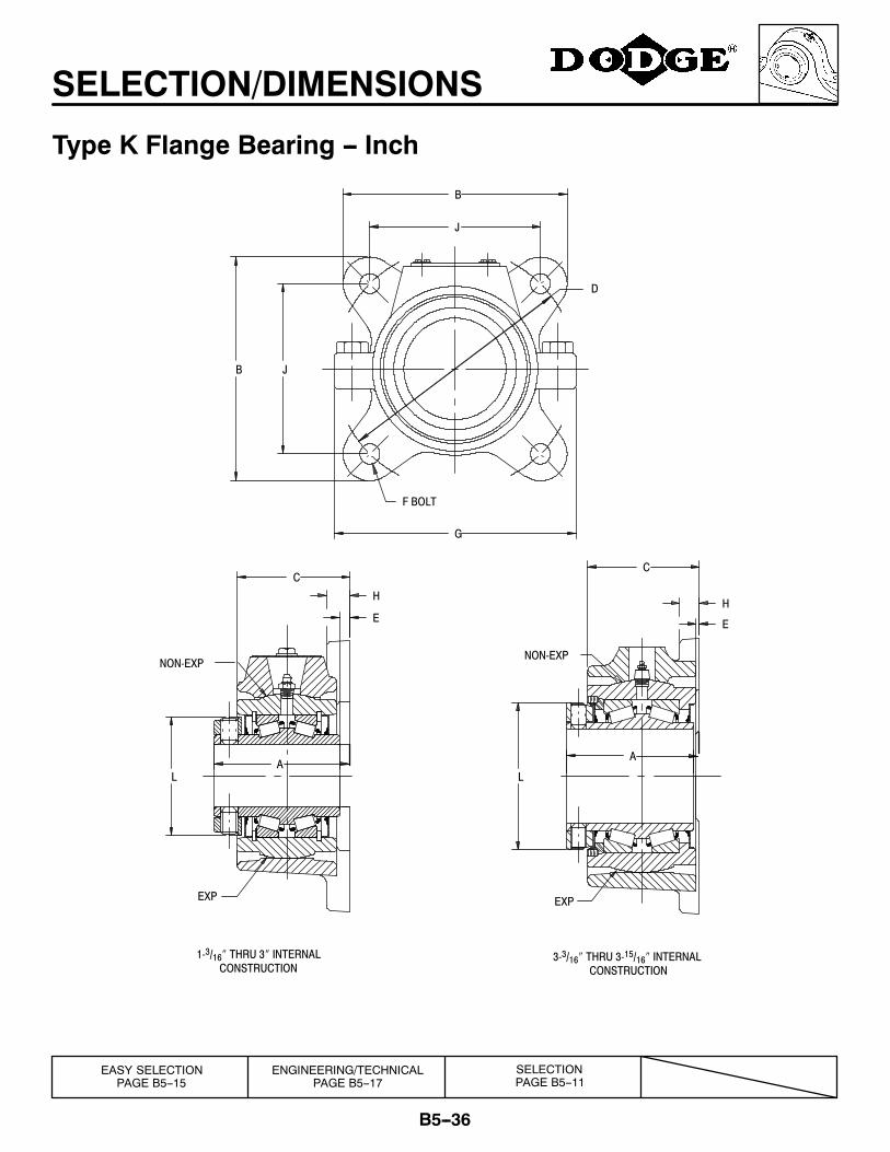
SELECTION/DIMENSIONS
Type K Flange Bearing -- Inch
L
H
E
C
A
L
CONSTRUCTION1-3/16″ THRU 3″ INTERNAL
CONSTRUCTION3-3/16″ THRU 3-15/16″ INTERNAL
H
E
C
A
D
NON-EXP
EXP
NON-EXP
EXP
F BOLT
G
JB
J
B
EASY SELECTIONPAGE B5--15
ENGINEERING/TECHNICALPAGE B5--17
SELECTIONPAGE B5--11
B5--37
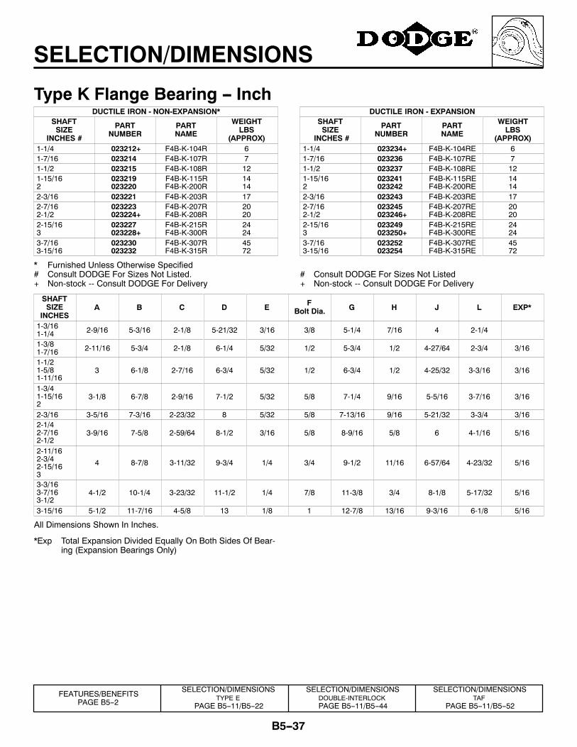
SELECTION/DIMENSIONS
Type K Flange Bearing -- InchDUCTILE IRON - NON-EXPANSION*
SHAFTSIZE
INCHES #
PARTNUMBER
PARTNAME
WEIGHTLBS
(APPROX)1-1/4 023212+ F4B-K-104R 61-7/16 023214 F4B-K-107R 71-1/2 023215 F4B-K-108R 121-15/162
023219023220
F4B-K-115RF4B-K-200R
1414
2-3/16 023221 F4B-K-203R 172-7/162-1/2
023223023224+
F4B-K-207RF4B-K-208R
2020
2-15/163
023227023228+
F4B-K-215RF4B-K-300R
2424
3-7/163-15/16
023230023232
F4B-K-307RF4B-K-315R
4572
* Furnished Unless Otherwise Specified# Consult DODGE For Sizes Not Listed.+ Non-stock -- Consult DODGE For Delivery
DUCTILE IRON - EXPANSIONSHAFTSIZE
INCHES #
PARTNUMBER
PARTNAME
WEIGHTLBS
(APPROX)1-1/4 023234+ F4B-K-104RE 61-7/16 023236 F4B-K-107RE 71-1/2 023237 F4B-K-108RE 121-15/162
023241023242
F4B-K-115REF4B-K-200RE
1414
2-3/16 023243 F4B-K-203RE 172-7/162-1/2
023245023246+
F4B-K-207REF4B-K-208RE
2020
2-15/163
023249023250+
F4B-K-215REF4B-K-300RE
2424
3-7/163-15/16
023252023254
F4B-K-307REF4B-K-315RE
4572
# Consult DODGE For Sizes Not Listed+ Non-stock -- Consult DODGE For Delivery
SHAFTSIZE
INCHESA B C D E F
Bolt Dia. G H J L EXP*
1-3/161-1/4 2-9/16 5-3/16 2-1/8 5-21/32 3/16 3/8 5-1/4 7/16 4 2-1/4
1-3/81-7/16 2-11/16 5-3/4 2-1/8 6-1/4 5/32 1/2 5-3/4 1/2 4-27/64 2-3/4 3/16
1-1/21-5/81-11/16
3 6-1/8 2-7/16 6-3/4 5/32 1/2 6-3/4 1/2 4-25/32 3-3/16 3/16
1-3/41-15/162
3-1/8 6-7/8 2-9/16 7-1/2 5/32 5/8 7-1/4 9/16 5-5/16 3-7/16 3/16
2-3/16 3-5/16 7-3/16 2-23/32 8 5/32 5/8 7-13/16 9/16 5-21/32 3-3/4 3/162-1/42-7/162-1/2
3-9/16 7-5/8 2-59/64 8-1/2 3/16 5/8 8-9/16 5/8 6 4-1/16 5/16
2-11/162-3/42-15/163
4 8-7/8 3-11/32 9-3/4 1/4 3/4 9-1/2 11/16 6-57/64 4-23/32 5/16
3-3/163-7/163-1/2
4-1/2 10-1/4 3-23/32 11-1/2 1/4 7/8 11-3/8 3/4 8-1/8 5-17/32 5/16
3-15/16 5-1/2 11-7/16 4-5/8 13 1/8 1 12-7/8 13/16 9-3/16 6-1/8 5/16
All Dimensions Shown In Inches.
*Exp Total Expansion Divided Equally On Both Sides Of Bear-ing (Expansion Bearings Only)
SELECTION/DIMENSIONSDOUBLE-INTERLOCKPAGE B5--11/B5--44
SELECTION/DIMENSIONSTAF
PAGE B5--11/B5--52
SELECTION/DIMENSIONSTYPE E
PAGE B5--11/B5--22
FEATURES/BENEFITSPAGE B5--2
B5--38
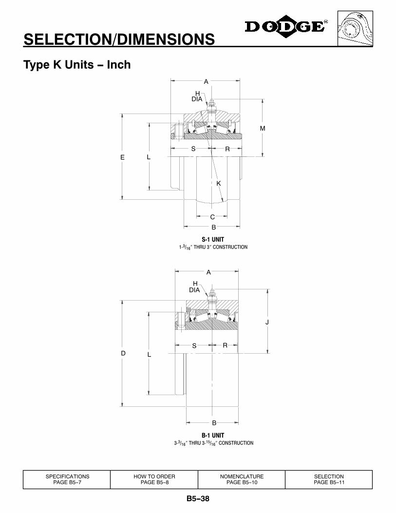
SELECTION/DIMENSIONS
Type K Units -- Inch
3-3/16″ THRU 3-15/16″ CONSTRUCTION
1-3/16″ THRU 3″ CONSTRUCTION
B-1 UNIT
S-1 UNIT
M
DIAH
K
B
C
LES R
A
DIAH
B
J
D LS R
A
SPECIFICATIONSPAGE B5--7
HOW TO ORDERPAGE B5--8
NOMENCLATUREPAGE B5--10
SELECTIONPAGE B5--11
B5--39
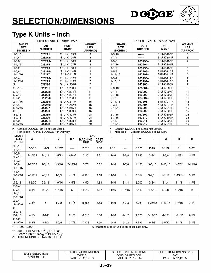
SELECTION/DIMENSIONS
Type K Units -- InchTYPE S-1 UNITS -- GRAY IRON
SHAFTSIZE
INCHES #
PARTNUMBER
PARTNAME
WEIGHTLBS
(APPROX)1-3/161-1/4
023271023272+
S1U-K-103RS1U-K-104R
33
1-3/81-7/16
023273+023274
S1U-K-106RS1U-K-107R
44
1-1/21-5/81-11/16
023275023276+023277
S1U-K-108RS1U-K-110RS1U-K-111R
555
1-3/41-15/162
023278+023279023280
S1U-K-112RS1U-K-115RS1U-K-200R
777
2-3/16 023281 S1U-K-203R 92-1/42-7/162-1/2
023282+023283023284+
S1U-K-204RS1U-K-207RS1U-K-208R
111111
2-11/162-3/42-15/163
023285+023286+023287023288
S1U-K-211RS1U-K-212RS1U-K-215RS1U-K-300R
15151515
3-3/163-7/163-1/23-15/16
023289+023290023291+023292
S1U-K-303RS1U-K-307RS1U-K-308RS1U-K-315R
28282840
# Consult DODGE For Sizes Not Listed.+ Non-stock -- Consult DODGE For Delivery
TYPE B-1 UNITS -- GRAY IRONSHAFTSIZE
INCHES #
PARTNUMBER
PARTNAME
WEIGHTLBS
(APPROX)1-3/161-1/4
------------
B1U-K-103RB1U-K-104R
33
1-3/81-7/16
023293+023294+
B1U-K-106RB1U-K-107R
44
1-1/21-5/81-11/16
023295+023296+023297+
B1U-K-108RB1U-K-110RB1U-K-111R
555
1-3/41-15/162
023298+023299+023300+
B1U-K-112RB1U-K-115RB1U-K-200R
777
2-3/16 023301+ B1U-K-203R 92-1/42-7/162-1/2
023302+023303+023304+
B1U-K-204RB1U-K-207RB1U-K-208R
111111
2-11/162-3/42-15/163
023305+023306+023307+023308+
B1U-K-211RB1U-K-212RB1U-K-215RB1U-K-300R
15151515
3-3/163-7/163-1/23-15/16
023309+023310+023311+023312+
B1U-K-303RB1U-K-307RB1U-K-308RB1U-K-315R
28282840
# Consult DODGE For Sizes Not Listed.+ Non-stock -- Consult DODGE For Delivery
SHAFT E %SHAFTSIZE
INCHESA B C D * MACHINE
SIDECASTSIDE
H J K ** L M R S
1-3/162 5/16 1 7/8 1 1/32 2 813 2 88 7/16 3 125 2 1/4 2 1/32 1 1 3/81-1/4 2-5/16 1-7/8 1-1/32 ---- 2.813 2.88 7/16 ---- 3.125 2-1/4 2-1/32 1 1-3/8
1-3/82 17/32 2 1/16 1 5/32 3 7/16 3 25 3 31 11/16 2 5/8 3 625 2 3/4 2 5/8 1 1/32 1 1/21-7/16 2-17/32 2-1/16 1-5/32 3-7/16 3.25 3.31 11/16 2-5/8 3.625 2-3/4 2-5/8 1-1/32 1-1/2
1-1/21-5/8 2-27/32 2-5/16 1-3/16 3-15/16 3.75 3.82 11/16 2-7/8 4.125 3-3/16 2-13/16 1-5/32 1-11/161-11/16
2 27/32 2 5/16 1 3/16 3 15/16 3.75 3.82 11/16 2 7/8 4.125 3 3/16 2 13/16 1 5/32 1 11/16
1-3/41-15/16 2-31/32 2-7/16 1-1/2 4-1/4 4.125 4.18 11/16 3 4.562 3-7/16 3-1/16 1-13/64 1-3/42
2 31/32 2 7/16 1 1/2 4 1/4 4.125 4.18 11/16 3 4.562 3 7/16 3 1/16 1 13/64 1 3/4
2-3/16 3-5/32 2-9/16 1-9/16 4-5/8 4.50 4.63 11/16 3-1/4 5.000 3-3/4 3-1/4 1-1/4 1-7/82-1/42-7/16 3-3/8 2-3/4 1-7/16 5 4.812 4.87 11/16 3-7/16 5.186 4-1/16 3-3/8 1-5/16 22-1/2
3 3/8 2 3/4 1 7/16 5 4.812 4.87 11/16 3 7/16 5.186 4 1/16 3 3/8 1 5/16 2
2-11/162-3/4
3 3/4 3 1 7/8 5 7/8 5 563 5 63 11/16 3 7/8 6 061 4 23/32 3 13/16 1 7/16 2 1/42-15/16 3-3/4 3 1-7/8 5-7/8 5.563 5.63 11/16 3-7/8 6.061 4-23/32 3-13/16 1-7/16 2-1/4
33-3/163-7/16 4-1/4 3-1/2 2 7-1/8 6.813 6.88 11/16 4-1/2 7.373 5-17/32 4-1/2 1-11/16 2-1/23-1/2
4 1/4 3 1/2 2 7 1/8 6.813 6.88 11/16 4 1/2 7.373 5 17/32 4 1/2 1 11/16 2 1/2
3-15/16 5-3/8 4-1/2 2-3/8 7-7/8 7.438 7.50 15/16 5-1/2 7.997 6-1/8 5-5/32 2-1/8 3-1/8
* +.000 - .002″ % Machine side of unit is on collar side only.** +.000 - .001 SIZES 1-3/16 THRU 3″± .0005″ SIZES 3-3/16 THRU 3-15/16″
ALL DIMENSIONS SHOWN IN INCHES
SELECTION/DIMENSIONSTYPE E
PAGE B5--11/B5--22
SELECTION/DIMENSIONSDOUBLE-INTERLOCKPAGE B5--11/B5--44
SELECTION/DIMENSIONSTAF
PAGE B5--11/B5--52
EASY SELECTIONPAGE B5--15
B5--40
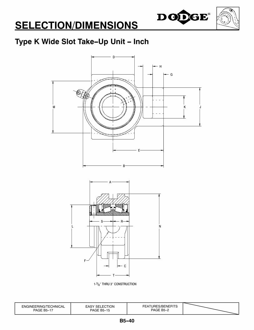
SELECTION/DIMENSIONS
Type K Wide Slot Take--Up Unit -- Inch
F
T
C
NLS R
A
K JM
H
G
D
E
B
1-3/8″ THRU 3″ CONSTRUCTION
ENGINEERING/TECHNICALPAGE B5--17
FEATURES/BENEFITSPAGE B5--2
EASY SELECTIONPAGE B5--15
B5--41
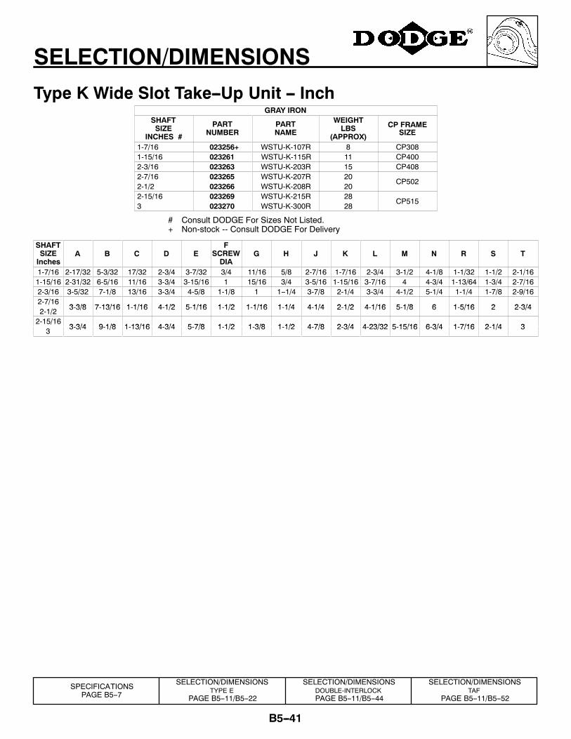
SELECTION/DIMENSIONS
Type K Wide Slot Take--Up Unit -- InchGRAY IRON
SHAFTSIZE
INCHES #
PARTNUMBER
PARTNAME
WEIGHTLBS
(APPROX)
CP FRAMESIZE
1-7/16 023256+ WSTU-K-107R 8 CP3081-15/16 023261 WSTU-K-115R 11 CP4002-3/16 023263 WSTU-K-203R 15 CP4082-7/162-1/2
023265023266
WSTU-K-207RWSTU-K-208R
2020
CP502
2-15/163
023269023270
WSTU-K-215RWSTU-K-300R
2828
CP515
# Consult DODGE For Sizes Not Listed.+ Non-stock -- Consult DODGE For Delivery
SHAFTSIZEInches
A B C D EF
SCREWDIA
G H J K L M N R S T
1-7/16 2-17/32 5-3/32 17/32 2-3/4 3-7/32 3/4 11/16 5/8 2-7/16 1-7/16 2-3/4 3-1/2 4-1/8 1-1/32 1-1/2 2-1/161-15/16 2-31/32 6-5/16 11/16 3-3/4 3-15/16 1 15/16 3/4 3-5/16 1-15/16 3-7/16 4 4-3/4 1-13/64 1-3/4 2-7/162-3/16 3-5/32 7-1/8 13/16 3-3/4 4-5/8 1-1/8 1 1--1/4 3-7/8 2-1/4 3-3/4 4-1/2 5-1/4 1-1/4 1-7/8 2-9/162-7/16
3 3/8 7 13/16 1 1/16 4 1/2 5 1/16 1 1/2 1 1/16 1 1/4 4 1/4 2 1/2 4 1/16 5 1/8 6 1 5/16 2 2 3/42-1/2 3-3/8 7-13/16 1-1/16 4-1/2 5-1/16 1-1/2 1-1/16 1-1/4 4-1/4 2-1/2 4-1/16 5-1/8 6 1-5/16 2 2-3/4
2-15/163 3/4 9 1/8 1 13/16 4 3/4 5 7/8 1 1/2 1 3/8 1 1/2 4 7/8 2 3/4 4 23/32 5 15/16 6 3/4 1 7/16 2 1/4 33 3-3/4 9-1/8 1-13/16 4-3/4 5-7/8 1-1/2 1-3/8 1-1/2 4-7/8 2-3/4 4-23/32 5-15/16 6-3/4 1-7/16 2-1/4 3
SELECTION/DIMENSIONSTYPE E
PAGE B5--11/B5--22
SELECTION/DIMENSIONSDOUBLE-INTERLOCKPAGE B5--11/B5--44
SELECTION/DIMENSIONSTAF
PAGE B5--11/B5--52
SPECIFICATIONSPAGE B5--7
B5--42
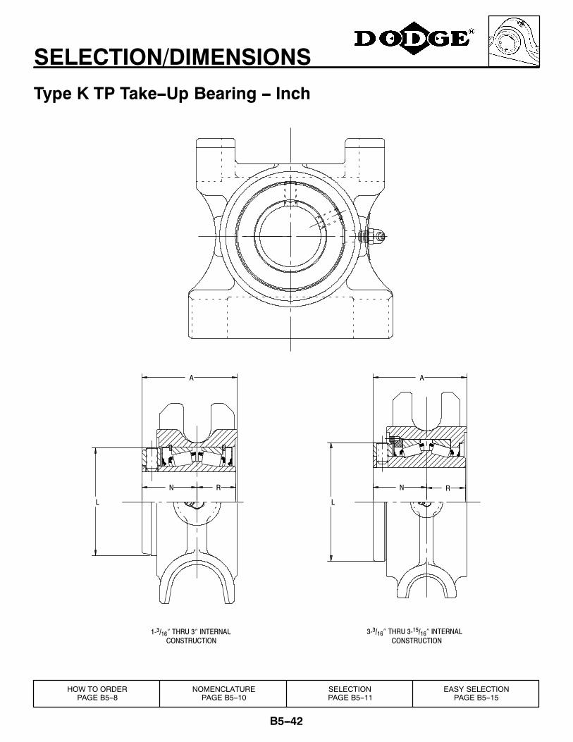
SELECTION/DIMENSIONS
Type K TP Take--Up Bearing -- Inch
N R N R
AA
LL
CONSTRUCTION1-3/16″ THRU 3″ INTERNAL
CONSTRUCTION3-3/16″ THRU 3-15/16″ INTERNAL
HOW TO ORDERPAGE B5--8
NOMENCLATUREPAGE B5--10
SELECTIONPAGE B5--11
EASY SELECTIONPAGE B5--15
B5--43
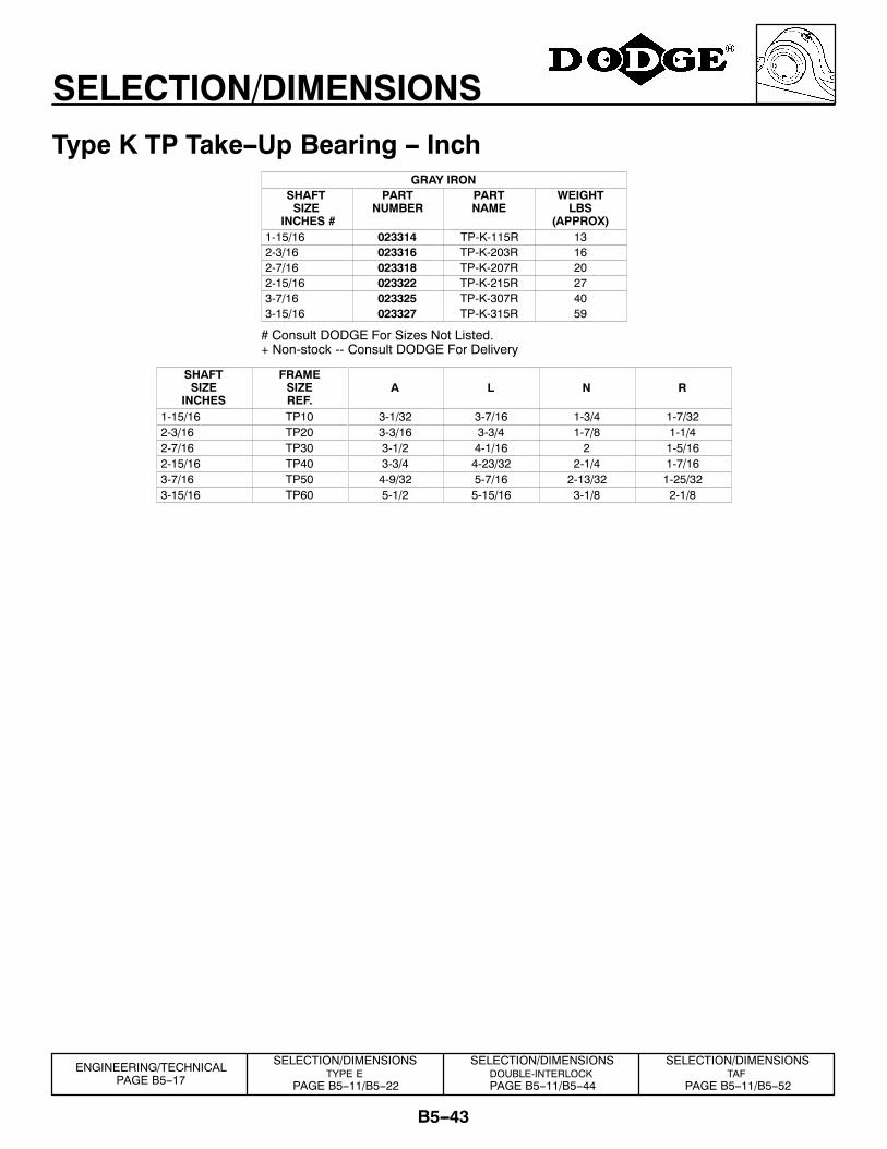
SELECTION/DIMENSIONS
Type K TP Take--Up Bearing -- InchGRAY IRON
SHAFTSIZE
INCHES #
PARTNUMBER
PARTNAME
WEIGHTLBS
(APPROX)1-15/16 023314 TP-K-115R 132-3/16 023316 TP-K-203R 162-7/16 023318 TP-K-207R 202-15/16 023322 TP-K-215R 273-7/163-15/16
023325023327
TP-K-307RTP-K-315R
4059
# Consult DODGE For Sizes Not Listed.+ Non-stock -- Consult DODGE For Delivery
SHAFTSIZE
INCHES
FRAMESIZEREF.
A L N R
1-15/16 TP10 3-1/32 3-7/16 1-3/4 1-7/322-3/16 TP20 3-3/16 3-3/4 1-7/8 1-1/42-7/16 TP30 3-1/2 4-1/16 2 1-5/162-15/16 TP40 3-3/4 4-23/32 2-1/4 1-7/163-7/16 TP50 4-9/32 5-7/16 2-13/32 1-25/323-15/16 TP60 5-1/2 5-15/16 3-1/8 2-1/8
SELECTION/DIMENSIONSTYPE E
PAGE B5--11/B5--22
SELECTION/DIMENSIONSDOUBLE-INTERLOCKPAGE B5--11/B5--44
SELECTION/DIMENSIONSTAF
PAGE B5--11/B5--52
ENGINEERING/TECHNICALPAGE B5--17
B5--44
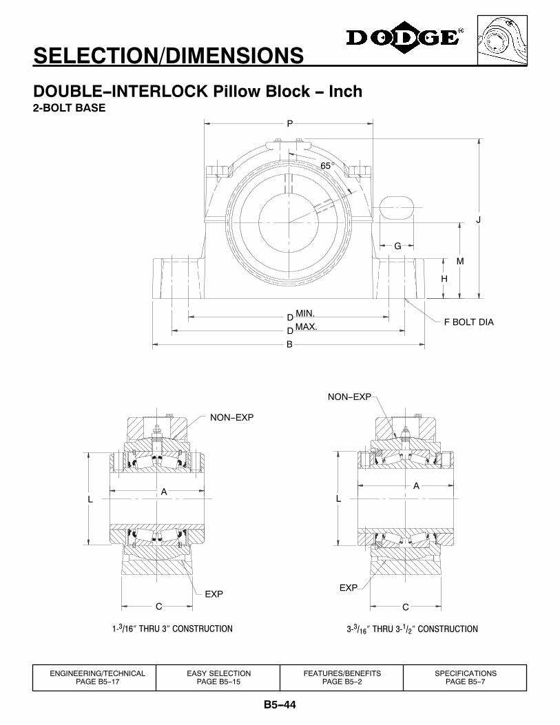
SELECTION/DIMENSIONS
DOUBLE--INTERLOCK Pillow Block -- Inch2-BOLT BASE
3-3/16″ THRU 3-1/2″ CONSTRUCTION1-3/16″ THRU 3″ CONSTRUCTION
P
J
G
H
M
F BOLT DIAMAX.MIN.
65_
DDB
A
EXP
NON--EXP
L
CEXP
NON--EXP
A
C
L
FEATURES/BENEFITSPAGE B5--2
SPECIFICATIONSPAGE B5--7
ENGINEERING/TECHNICALPAGE B5--17
EASY SELECTIONPAGE B5--15
B5--45
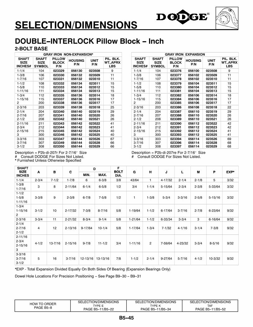
SELECTION/DIMENSIONS
DOUBLE--INTERLOCK Pillow Block -- Inch2-BOLT BASE
GRAY IRON NON-EXPANSION*SHAFTSIZE
INCHES#
SHAFTSIZE
SYMBOL
PILLOWBLOCKP/N
HOUSINGP/N
UNITP/N
PIL. BLK.WT.,APRX
LBS1-1/4 104 023329 056130 023508 91-3/81-7/16
106107
023330023331
056132056132
023509023510
1111
1-1/21-5/81-11/16
108110111
023332023333023334
056134056134056134
023511023512023513
151515
1-3/41-15/162
112115200
023335023337023338
056136056136056136
023514023516023517
181717
2-3/16 203 023339 056138 023518 252-1/42-7/162-1/2
204207208
023340023341023342
056140056140056140
023519023520023521
292626
2-11/162-3/42-15/163
211212215300
023343023344023345023346
056142056142056142056142
023522023523023524023525
41414040
3-3/163-7/163-1/2
303307308
023347023349023350
056144056144056144
023526023528023529
676666
Description = P2b-di-207r For 2-7/16″ Size# Consult DODGE For Sizes Not Listed.
GRAY IRON EXPANSIONSHAFTSIZE
INCHES#
SHAFTSIZE
SYMBOL
PILLOWBLOCKP/N
HOUSINGP/N
UNITP/N
PIL. BLK.WT.,APRX
LBS1-1/4 104 023376 056100 023508 91-3/81-7/16
106107
023377023378
056102056102
023509023510
1111
1-1/21-5/81-11/16
108110111
023379023380023381
056104056104056104
023511023512023513
151515
1-3/41-15/162
112115200
023382023384023385
056106056106056106
023514023516023517
181717
2-3/16 203 023386 056108 023518 222-1/42-7/162-1/2
204207208
023387023388023389
056110056110056110
023519023520023521
292626
2-11/162-3/42-15/163
211212215300
023390023391023392023393
056112056112056112056112
023522023523023524023525
42424141
3-3/163-7/163-1/2
303307308
023394023396023397
056114056114056114
023526023528023529
696868
Description = P2b-di-207re For 2-7/16″ Size# Consult DODGE For Sizes Not Listed.
* Furnished Unless Otherwise Specified
SHAFTSIZE A B C
D FBOLT G H J L M P EXP*SIZE
INCHESA B C
MIN. MAX.BOLTDIA.
G H J L M P EXP*
1-1/4 2-3/4 7-1/2 1-7/8 6 6-3/8 3/8 43/64 1 4-17/32 2-1/4 2-1/8 5 3/321-3/81-7/16
3 8 2-11/64 6-1/4 6-5/8 1/2 3/4 1-1/4 5-15/64 2-3/4 2-3/8 5-33/64 3/32
1-1/21-5/81-11/16
3-3/8 9 2-3/8 6-7/8 7-5/8 1/2 1 1-3/8 5-3/4 3-3/16 2-5/8 5-15/16 3/32
1-3/41-15/162
3-1/2 10 2-17/32 7-3/8 8-7/16 5/8 1-19/64 1-1/2 6-17/64 3-7/16 2-7/8 6-23/64 9/32
2-3/16 3-3/4 11 2-21/32 8-3/4 9-1/4 5/8 1-21/64 1-1/2 6-33/34 3-3/4 3 6-16/64 9/322-1/42-7/162-1/2
4 12 2-13/16 9-17/64 10-1/4 5/8 1-17/64 1-3/4 7-1/32 4-1/16 3-1/4 7-3/8 9/32
2-11/162-3/42-15/163
4-1/2 13-7/16 2-15/16 9-7/8 11-1/2 3/4 1-11/16 2 7-59/64 4-23/32 3-3/4 8-5/16 9/32
3-3/163-7/163-1/2
5 16 3-7/16 12-13/16 13-13/16 7/8 1-1/2 2-1/4 9-27/64 5-7/16 4-1/2 10-3/32 9/32
*EXP - Total Expansion Divided Equally On Both Sides Of Bearing (Expansion Bearings Only)
Dowel Hole Locations For Precision Positioning -- See Page B9--30 -- B9--31
SELECTION/DIMENSIONSTYPE E
PAGE B5--11/B5--22
SELECTION/DIMENSIONSTAF
PAGE B5--11/B5--52
HOW TO ORDERPAGE B5--8
SELECTION/DIMENSIONSTYPE K
PAGE B5--11/B5--34
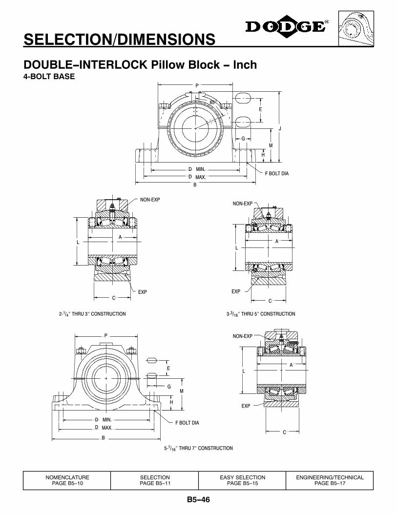
B5--46
SELECTION/DIMENSIONS
DOUBLE--INTERLOCK Pillow Block -- Inch4-BOLT BASE
C
DD
5-7/16″ THRU 7″ CONSTRUCTION
3-3/16″ THRU 5″ CONSTRUCTION
NON-EXP
EXP
EA
L
C
H
GM
B
E
A
EXP
L
NON-EXPNON-EXP
AL
CEXP
P
J
H
2-1/4″ THRU 3″ CONSTRUCTION
GM
F BOLT DIAMAX.
MIN.
65°
B
DD MAX.
MIN.
P
F BOLT DIA
NOMENCLATUREPAGE B5--10
SELECTIONPAGE B5--11
EASY SELECTIONPAGE B5--15
ENGINEERING/TECHNICALPAGE B5--17
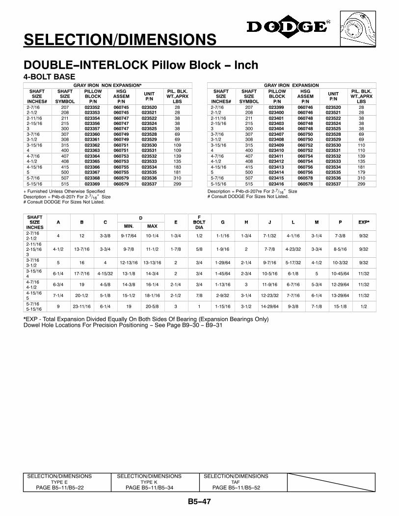
B5--47
SELECTION/DIMENSIONS
DOUBLE--INTERLOCK Pillow Block -- Inch4-BOLT BASE
GRAY IRON NON EXPANSION*SHAFTSIZE
INCHES#
SHAFTSIZE
SYMBOL
PILLOWBLOCKP/N
HSGASSEMP/N
UNITP/N
PIL. BLK.WT.,APRX
LBS2-7/162-1/2
207208
023352023353
060745060745
023520023521
2828
2-11/162-15/163
211215300
023354023356023357
060747060747060747
023522023524023525
383838
3-7/163-1/2
307308
023360023361
060749060749
023528023529
6969
3-15/164
315400
023362023363
060751060751
023530023531
109109
4-7/164-1/2
407408
023364023365
060753060753
023532023533
139135
4-15/165
415500
023366023367
060755060755
023534023535
183181
5-7/16 507 023368 060579 023536 3105-15/16 515 023369 060579 023537 299
+ Furnished Unless Otherwise SpecifiedDescription = P4b-di-207r For 2-7/16″ Size# Consult DODGE For Sizes Not Listed.
GRAY IRON EXPANSIONSHAFTSIZE
INCHES#
SHAFTSIZE
SYMBOL
PILLOWBLOCKP/N
HSGASSEMP/N
UNITP/N
PIL. BLK.WT.,APRX
LBS2-7/162-1/2
207208
023399023400
060746060746
023520023521
2828
2-11/162-15/163
211215300
023401023403023404
060748060748060748
023522023524023525
383838
3-7/163-1/2
307308
023407023408
060750060750
023528023529
6969
3-15/164
315400
023409023410
060752060752
023530023531
110110
4-7/164-1/2
407408
023411023412
060754060754
023532023533
139135
4-15/165
415500
023413023414
060756060756
023534023535
181179
5-7/16 507 023415 060578 023536 3105-15/16 515 023416 060578 023537 299
Description = P4b-di-207re For 2-7/16″ Size# Consult DODGE For Sizes Not Listed.
SHAFTSIZE A B C
DE
FBOLT G H J L M P EXP*SIZE
INCHESA B C
MIN. MAXE BOLT
DIAG H J L M P EXP*
2-7/162-1/2 4 12 3-3/8 9-17/64 10-1/4 1-3/4 1/2 1-1/16 1-3/4 7-1/32 4-1/16 3-1/4 7-3/8 9/32
2-11/162-15/163
4-1/2 13-7/16 3-3/4 9-7/8 11-1/2 1-7/8 5/8 1-9/16 2 7-7/8 4-23/32 3-3/4 8-5/16 9/32
3-7/163-1/2 5 16 4 12-13/16 13-13/16 2 3/4 1-29/64 2-1/4 9-7/16 5-17/32 4-1/2 10-3/32 9/32
3-15/164 6-1/4 17-7/16 4-15/32 13-1/8 14-3/4 2 3/4 1-45/64 2-3/4 10-5/16 6-1/8 5 10-45/64 11/32
4-7/164-1/2 6-3/4 19 4-5/8 14-3/8 16-1/4 2-1/4 3/4 1-13/16 3 11-9/16 6-7/16 5-3/4 12-29/64 11/32
4-15/165 7-1/4 20-1/2 5-1/8 15-1/2 18-1/16 2-1/2 7/8 2-9/32 3-1/4 12-23/32 7-7/16 6-1/4 13-29/64 11/32
5-7/165-15/16 9 23-11/16 6-1/4 19 20-5/8 3 1 1-15/16 3-1/2 14-29/64 9-3/8 7-1/8 15-1/8 1/2
*EXP - Total Expansion Divided Equally On Both Sides Of Bearing (Expansion Bearings Only)Dowel Hole Locations For Precision Positioning -- See Page B9--30 -- B9--31
SELECTION/DIMENSIONSTYPE E
PAGE B5--11/B5--22
SELECTION/DIMENSIONSTAF
PAGE B5--11/B5--52
SELECTION/DIMENSIONSTYPE K
PAGE B5--11/B5--34
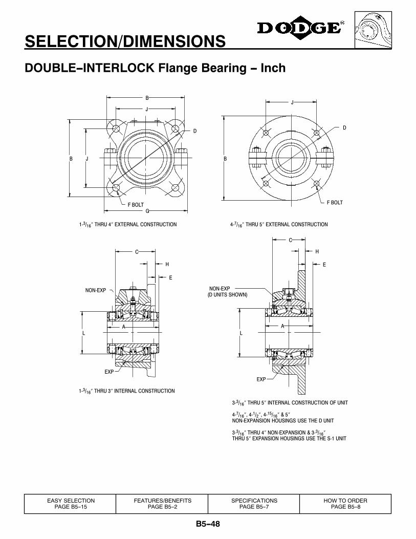
B5--48
SELECTION/DIMENSIONS
DOUBLE--INTERLOCK Flange Bearing -- Inch
3-3/16″ THRU 5″ INTERNAL CONSTRUCTION OF UNIT
4-7/16″, 4-1/2″, 4-15/16″ & 5″NON-EXPANSION HOUSINGS USE THE D UNIT
3-3/16″ THRU 4″ NON-EXPANSION & 3-3/16″THRU 5″ EXPANSION HOUSINGS USE THE S-1 UNIT
(D UNITS SHOWN)NON-EXP
J
D
EXP
NON-EXP
EXP
L
E
H
C
A
H
C
A
E
L
D
B
4-7/16″ THRU 5″ EXTERNAL CONSTRUCTION
F BOLT
1-3/16″ THRU 4″ EXTERNAL CONSTRUCTION
G
JB
J
B
1-3/16″ THRU 3″ INTERNAL CONSTRUCTION
F BOLT
FEATURES/BENEFITSPAGE B5--2
SPECIFICATIONSPAGE B5--7
HOW TO ORDERPAGE B5--8
EASY SELECTIONPAGE B5--15
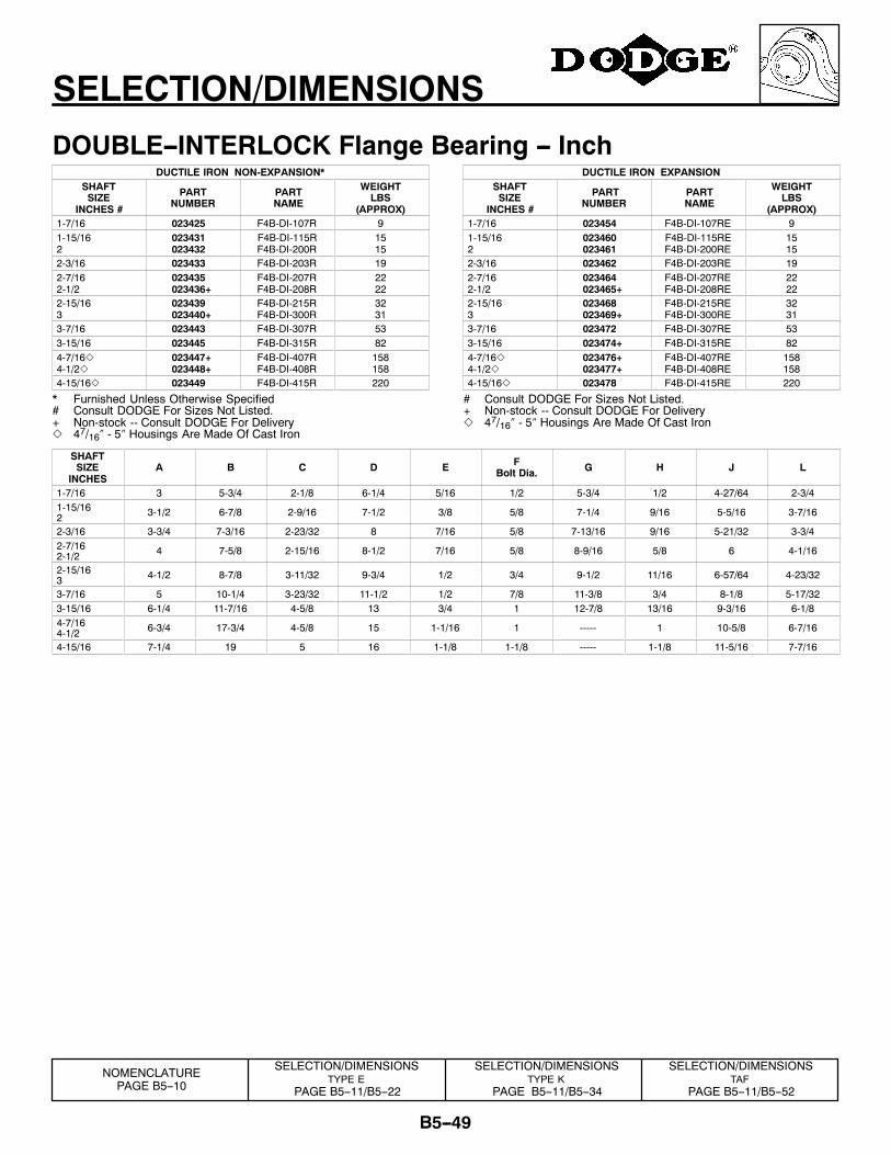
B5--49
SELECTION/DIMENSIONS
DOUBLE--INTERLOCK Flange Bearing -- InchDUCTILE IRON NON-EXPANSION*
SHAFTSIZE
INCHES #
PARTNUMBER
PARTNAME
WEIGHTLBS
(APPROX)1-7/16 023425 F4B-DI-107R 91-15/162
023431023432
F4B-DI-115RF4B-DI-200R
1515
2-3/16 023433 F4B-DI-203R 192-7/162-1/2
023435023436+
F4B-DI-207RF4B-DI-208R
2222
2-15/163
023439023440+
F4B-DI-215RF4B-DI-300R
3231
3-7/16 023443 F4B-DI-307R 533-15/16 023445 F4B-DI-315R 824-7/16Z4-1/2Z
023447+023448+
F4B-DI-407RF4B-DI-408R
158158
4-15/16Z 023449 F4B-DI-415R 220
* Furnished Unless Otherwise Specified# Consult DODGE For Sizes Not Listed.+ Non-stock -- Consult DODGE For DeliveryZ 47/16″ - 5″ Housings Are Made Of Cast Iron
DUCTILE IRON EXPANSIONSHAFTSIZE
INCHES #
PARTNUMBER
PARTNAME
WEIGHTLBS
(APPROX)1-7/16 023454 F4B-DI-107RE 91-15/162
023460023461
F4B-DI-115REF4B-DI-200RE
1515
2-3/16 023462 F4B-DI-203RE 192-7/162-1/2
023464023465+
F4B-DI-207REF4B-DI-208RE
2222
2-15/163
023468023469+
F4B-DI-215REF4B-DI-300RE
3231
3-7/16 023472 F4B-DI-307RE 533-15/16 023474+ F4B-DI-315RE 824-7/16Z4-1/2Z
023476+023477+
F4B-DI-407REF4B-DI-408RE
158158
4-15/16Z 023478 F4B-DI-415RE 220
# Consult DODGE For Sizes Not Listed.+ Non-stock -- Consult DODGE For DeliveryZ 47/16″ - 5″ Housings Are Made Of Cast Iron
SHAFTSIZE
INCHESA B C D E F
Bolt Dia. G H J L
1-7/16 3 5-3/4 2-1/8 6-1/4 5/16 1/2 5-3/4 1/2 4-27/64 2-3/41-15/162 3-1/2 6-7/8 2-9/16 7-1/2 3/8 5/8 7-1/4 9/16 5-5/16 3-7/16
2-3/16 3-3/4 7-3/16 2-23/32 8 7/16 5/8 7-13/16 9/16 5-21/32 3-3/42-7/162-1/2 4 7-5/8 2-15/16 8-1/2 7/16 5/8 8-9/16 5/8 6 4-1/16
2-15/163 4-1/2 8-7/8 3-11/32 9-3/4 1/2 3/4 9-1/2 11/16 6-57/64 4-23/32
3-7/16 5 10-1/4 3-23/32 11-1/2 1/2 7/8 11-3/8 3/4 8-1/8 5-17/323-15/16 6-1/4 11-7/16 4-5/8 13 3/4 1 12-7/8 13/16 9-3/16 6-1/84-7/164-1/2 6-3/4 17-3/4 4-5/8 15 1-1/16 1 ----- 1 10-5/8 6-7/16
4-15/16 7-1/4 19 5 16 1-1/8 1-1/8 ----- 1-1/8 11-5/16 7-7/16
SELECTION/DIMENSIONSTYPE E
PAGE B5--11/B5--22
SELECTION/DIMENSIONSTAF
PAGE B5--11/B5--52
SELECTION/DIMENSIONSTYPE K
PAGE B5--11/B5--34
NOMENCLATUREPAGE B5--10
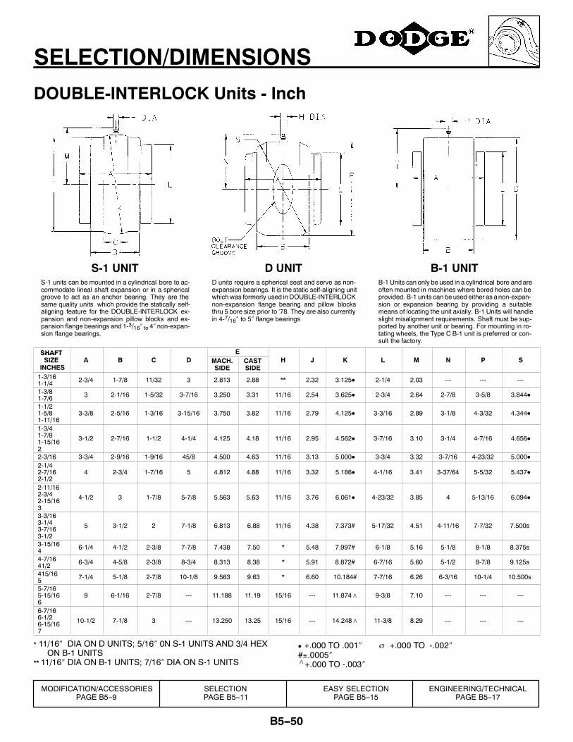
B5--50
SELECTION/DIMENSIONS
DOUBLE-INTERLOCK Units - Inch
S-1 units can be mounted in a cylindrical bore to ac-commodate lineal shaft expansion or in a sphericalgroove to act as an anchor bearing. They are thesame quality units which provide the statically self-aligning feature for the DOUBLE-INTERLOCK ex-pansion and non-expansion pillow blocks and ex-pansion flange bearings and 1-3/16″ to 4″ non-expan-sion flange bearings.
D units require a spherical seat and serve as non-expansion bearings. It is the static self-aligning unitwhich was formerly used in DOUBLE-INTERLOCKnon-expansion flange bearing and pillow blocksthru 5 bore size prior to ’78. They are also currentlyin 4-7/16″ to 5″ flange bearings
B-1 Units can only be used in a cylindrical bore and areoften mounted in machines where bored holes can beprovided. B-1 units can be used either as anon-expan-sion or expansion bearing by providing a suitablemeans of locating the unit axially. B-1 Units will handleslight misalignment requirements. Shaft must be sup-ported by another unit or bearing. For mounting in ro-tating wheels, the Type C B-1 unit is preferred or con-sult the factory.
S-1 UNIT D UNIT B-1 UNIT
SHAFT ESHAFTSIZE
INCHESA B C D MACH.
SIDECASTSIDE
H J K L M N P S
1-3/161-1/4 2-3/4 1-7/8 11/32 3 2.813 2.88 ** 2.32 3.125D 2-1/4 2.03 --- --- ---
1-3/81-7/6 3 2-1/16 1-5/32 3-7/16 3.250 3.31 11/16 2.54 3.625D 2-3/4 2.64 2-7/8 3-5/8 3.844D
1-1/21-5/81-11/16
3-3/8 2-5/16 1-3/16 3-15/16 3.750 3.82 11/16 2.79 4.125D 3-3/16 2.89 3-1/8 4-3/32 4.344D
1-3/41-7/81-15/162
3-1/2 2-7/16 1-1/2 4-1/4 4.125 4.18 11/16 2.95 4.562D 3-7/16 3.10 3-1/4 4-7/16 4.656D
2-3/16 3-3/4 2-9/16 1-9/16 45/8 4.500 4.63 11/16 3.13 5.000D 3-3/4 3.32 3-7/16 4-23/32 5.000D2-1/42-7/162-1/2
4 2-3/4 1-7/16 5 4.812 4.88 11/16 3.32 5.186D 4-1/16 3.41 3-37/64 5-5/32 5.437D
2-11/162-3/42-15/163
4-1/2 3 1-7/8 5-7/8 5.563 5.63 11/16 3.76 6.061D 4-23/32 3.85 4 5-13/16 6.094D
3-3/163-1/43-7/163-1/2
5 3-1/2 2 7-1/8 6.813 6.88 11/16 4.38 7.373# 5-17/32 4.51 4-11/16 7-7/32 7.500s
3-15/164 6-1/4 4-1/2 2-3/8 7-7/8 7.438 7.50 * 5.48 7.997# 6-1/8 5.16 5-1/8 8-1/8 8.375s
4-7/1641/2 6-3/4 4-5/8 2-3/8 8-3/4 8.313 8.38 * 5.91 8.872# 6-7/16 5.60 5-1/2 8-7/8 9.125s
415/165 7-1/4 5-1/8 2-7/8 10-1/8 9.563 9.63 * 6.60 10.184# 7-7/16 6.26 6-3/16 10-1/4 10.500s
5-7/165-15/166
9 6-1/16 2-7/8 --- 11.188 11.19 15/16 --- 11.874∧ 9-3/8 7.10 --- --- ---
6-7/166-1/26-15/167
10-1/2 7-1/8 3 --- 13.250 13.25 15/16 --- 14.248∧ 11-3/8 8.29 --- --- ---
* 11/16″ DIA ON D UNITS; 5/16″ 0N S-1 UNITS AND 3/4 HEXON B-1 UNITS
** 11/16″ DIA ON B-1 UNITS; 7/16″ DIA ON S-1 UNITS
D +.000 TO .001″ σ +.000 TO -.002″#±.0005″∧+.000 TO -.003″
SELECTIONPAGE B5--11
EASY SELECTIONPAGE B5--15
ENGINEERING/TECHNICALPAGE B5--17
MODIFICATION/ACCESSORIESPAGE B5--9
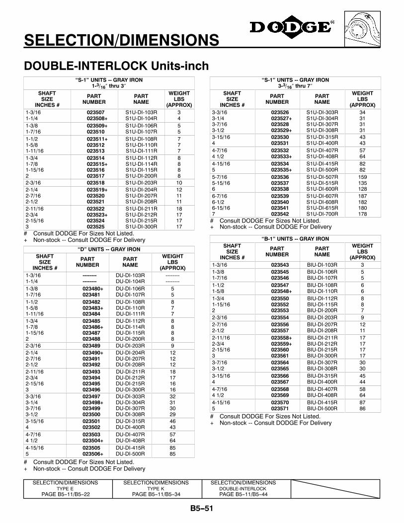
B5--51
SELECTION/DIMENSIONS
DOUBLE-INTERLOCK Units-inch“S-1” UNITS -- GRAY IRON
1-3/16″ thru 3″SHAFTSIZE
INCHES #
PARTNUMBER
PARTNAME
WEIGHTLBS
(APPROX)1-3/161-1/4
023507023508+
S1U-DI-103RS1U-DI-104R
34
1-3/81-7/16
023509+023510
S1U-DI-106RS1U-DI-107R
55
1-1/21-5/81-11/16
023511+023512023513
S1U-DI-108RS1U-DI-110RS1U-DI-111R
777
1-3/41-7/81-15/162
023514023515+023516023517
S1U-DI-112RS1U-DI-114RS1U-DI-115RS1U-DI-200R
8888
2-3/16 023518 S1U-DI-203R 102-1/42-7/162-1/2
023519+023520023521
S1U-DI-204RS1U-DI-207RS1U-DI-208R
121111
2-11/162-3/42-15/163
023522023523+023524023525
S1U-DI-211RS1U-DI-212RS1U-DI-215RS1U-DI-300R
18171717
# Consult DODGE For Sizes Not Listed.+ Non-stock -- Consult DODGE For Delivery
“D” UNITS -- GRAY IRONSHAFTSIZE
INCHES #
PARTNUMBER
PARTNAME
WEIGHTLBS
(APPROX)1-3/161-1/4
----------------
DU-DI-103RDU-DI-104R
----------------
1-3/81-7/16
023480+023481
DU-DI-106RDU-DI-107R
55
1-1/21-5/81-11/16
023482023483+023484
DU-DI-108RDU-DI-110RDU-DI-111R
877
1-3/41-7/81-15/162
023485023486+023487023488
DU-DI-112RDU-DI-114RDU-DI-115RDU-DI-200R
8888
2-3/16 023489 DU-DI-203R 92-1/42-7/162-1/2
023490+023491023492
DU-DI-204RDU-DI-207RDU-DI-208R
121212
2-11/162-3/42-15/163
023493023494023495023496
DU-DI-211RDU-DI-212RDU-DI-215RDU-DI-300R
18171616
3-3/163-1/43-7/163-1/2
023497023498+023499023500
DU-DI-303RDU-DI-304RDU-DI-307RDU-DI-308R
32313029
3-15/164
023501023502
DU-DI-315RDU-DI-400R
4643
4-7/164 1/2
023503023504+
DU-DI-407RDU-DI-408R
5764
4-15/165
023505023506+
DU-DI-415RDU-DI-500R
8585
# Consult DODGE For Sizes Not Listed.+ Non-stock -- Consult DODGE For Delivery
“S-1” UNITS -- GRAY IRON3-3/16″ thru 7″
SHAFTSIZE
INCHES #
PARTNUMBER
PARTNAME
WEIGHTLBS
(APPROX)3-3/163-1/43-7/163-1/2
023526023527+023528023529+
S1U-DI-303RS1U-DI-304RS1U-DI-307RS1U-DI-308R
34313131
3-15/164
023530023531
S1U-DI-315RS1U-DI-400R
4343
4-7/164 1/2
023532023533+
S1U-DI-407RS1U-DI-408R
5764
4-15/165
023534023535+
S1U-DI-415RS1U-DI-500R
8282
5-7/165-15/166
023536023537023538
S1U-DI-507RS1U-DI-515RS1U-DI-600R
159135128
6-7/166-1/26-15/167
023539023540023541023542
S1U-DI-607RS1U-DI-608RS1U-DI-615RS1U-DI-700R
187182180178
# Consult DODGE For Sizes Not Listed.+ Non-stock -- Consult DODGE For Delivery
“B-1” UNITS -- GRAY IRONSHAFTSIZE
INCHES #
PARTNUMBER
PARTNAME
WEIGHTLBS
(APPROX)1-3/16 023543 BIU-DI-103R 31-3/81-7/16
023545023546
BIU-DI-106RBIU-DI-107R
55
1-1/21-5/8
023547023548+
BIU-DI-108RBIU-DI-110R
66
1-3/41-15/162
023550023552023553
BIU-DI-112RBIU-DI-115RBIU-DI-200R
887
2-3/16 023554 BIU-DI-203R 92-7/162-1/2
023556023557
BIU-DI-207RBIU-DI-208R
1211
2-11/162-3/42-15/163
023558+023559+023560023561
BIU-DI-211RBIU-DI-212RBIU-DI-215RBIU-DI-300R
17171717
3-7/163-1/2
023564023565
BIU-DI-307RBIU-DI-308R
3030
3-15/164
023566023567
BIU-DI-315RBIU-DI-400R
4544
4-7/164 1/2
023568023569
BIU-DI-407RBIU-DI-408R
5864
4-15/165
023570023571
BIU-DI-415RBIU-DI-500R
8786
# Consult DODGE For Sizes Not Listed.+ Non-stock -- Consult DODGE For Delivery
SELECTION/DIMENSIONSTYPE E
PAGE B5--11/B5--22
SELECTION/DIMENSIONSTYPE K
PAGE B5--11/B5--34
SELECTION/DIMENSIONSDOUBLE-INTERLOCKPAGE B5--11/B5--44
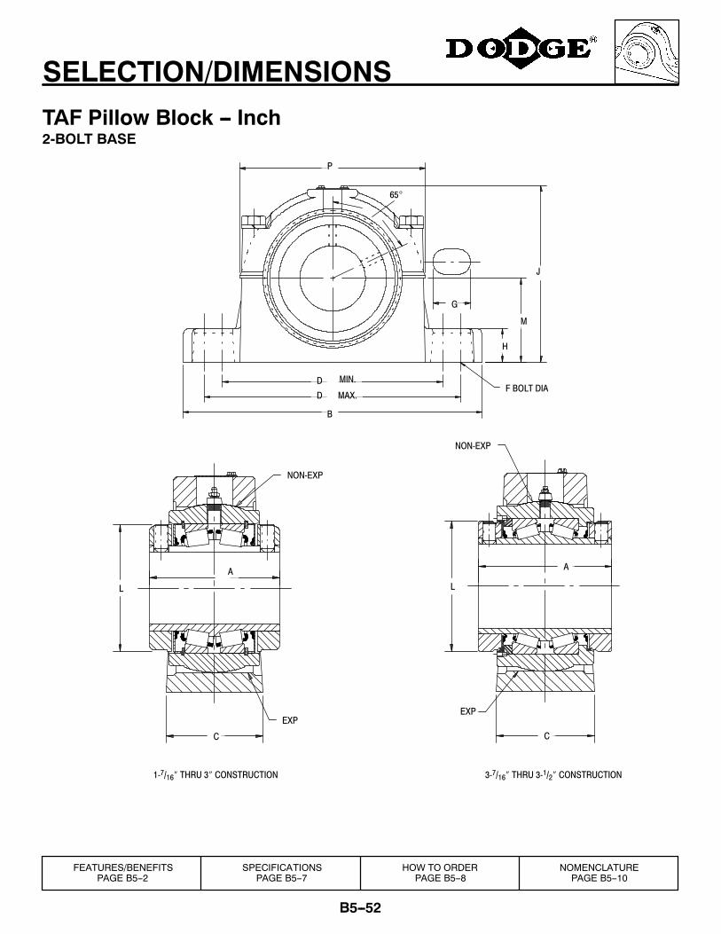
B5--52
SELECTION/DIMENSIONS
TAF Pillow Block -- Inch2-BOLT BASE
P
D
D
A
C
EXP
L
NON-EXP
3-7/16″ THRU 3-1/2″ CONSTRUCTION
NON-EXP
A
L
C
EXP
J
H
1-7/16″ THRU 3″ CONSTRUCTION
G
M
F BOLT DIAMAX.
MIN.
65°
B
FEATURES/BENEFITSPAGE B5--2
SPECIFICATIONSPAGE B5--7
HOW TO ORDERPAGE B5--8
NOMENCLATUREPAGE B5--10
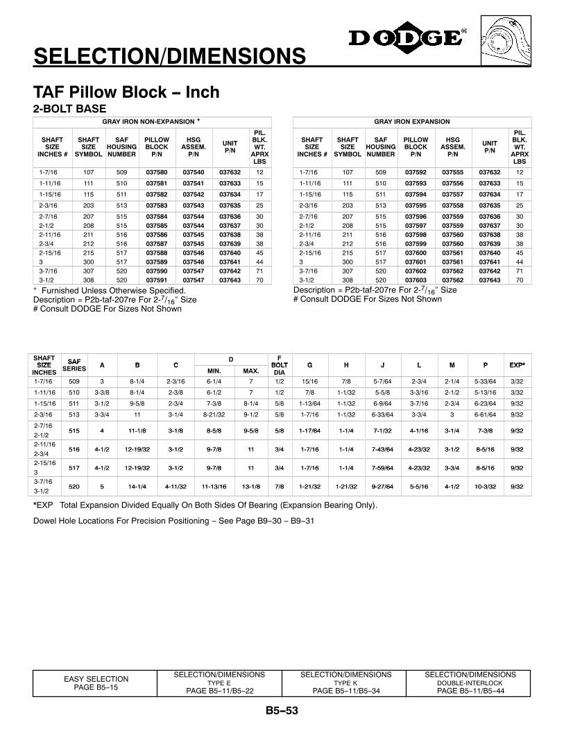
B5--53
SELECTION/DIMENSIONS
TAF Pillow Block -- Inch2-BOLT BASE
GRAY IRON NON-EXPANSION +
SHAFTSIZE
INCHES #
SHAFTSIZE
SYMBOL
SAFHOUSINGNUMBER
PILLOWBLOCKP/N
HSGASSEM.P/N
UNITP/N
PIL.BLK.WT.APRXLBS
1-7/16 107 509 037580 037540 037632 12
1-11/16 111 510 037581 037541 037633 15
1-15/16 115 511 037582 037542 037634 17
2-3/16 203 513 037583 037543 037635 25
2-7/16 207 515 037584 037544 037636 302-1/2 208 515 037585 037544 037637 302-11/16 211 516 037586 037545 037638 382-3/4 212 516 037587 037545 037639 382-15/16 215 517 037588 037546 037640 453 300 517 037589 037546 037641 443-7/16 307 520 037590 037547 037642 713-1/2 308 520 037591 037547 037643 70
+ Furnished Unless Otherwise Specified.Description = P2b-taf-207re For 2-7/16″ Size# Consult DODGE For Sizes Not Shown
GRAY IRON EXPANSION
SHAFTSIZE
INCHES #
SHAFTSIZE
SYMBOL
SAFHOUSINGNUMBER
PILLOWBLOCKP/N
HSGASSEM.P/N
UNITP/N
PIL.BLK.WT.APRXLBS
1-7/16 107 509 037592 037555 037632 12
1-11/16 111 510 037593 037556 037633 15
1-15/16 115 511 037594 037557 037634 17
2-3/16 203 513 037595 037558 037635 25
2-7/16 207 515 037596 037559 037636 302-1/2 208 515 037597 037559 037637 302-11/16 211 516 037598 037560 037638 382-3/4 212 516 037599 037560 037639 382-15/16 215 517 037600 037561 037640 453 300 517 037601 037561 037641 443-7/16 307 520 037602 037562 037642 713-1/2 308 520 037603 037562 037643 70
Description = P2b-taf-207re For 2-7/16″ Size# Consult DODGE For Sizes Not Shown
SHAFTSIZE SAF A B C
D FBOLT G H J L M P EXP*SIZE
INCHES
SAFSERIES A B C
MIN. MAX.BOLTDIA
G H J L M P EXP*
1-7/16 509 3 8-1/4 2-3/16 6-1/4 7 1/2 15/16 7/8 5-7/64 2-3/4 2-1/4 5-33/64 3/32
1-11/16 510 3-3/8 8-1/4 2-3/8 6-1/2 7 1/2 7/8 1-1/32 5-5/8 3-3/16 2-1/2 5-13/16 3/32
1-15/16 511 3-1/2 9-5/8 2-3/4 7-3/8 8-1/4 5/8 1-13/64 1-1/32 6-9/64 3-7/16 2-3/4 6-23/64 9/32
2-3/16 513 3-3/4 11 3-1/4 8-21/32 9-1/2 5/8 1-7/16 1-1/32 6-33/64 3-3/4 3 6-61/64 9/32
2-7/16515 4 11-1/8 3-1/8 8-5/8 9-5/8 5/8 1-17/64 1-1/4 7-1/32 4-1/16 3-1/4 7-3/8 9/32
2-1/2515 4 11-1/8 3-1/8 8-5/8 9-5/8 5/8 1-17/64 1-1/4 7-1/32 4-1/16 3-1/4 7-3/8 9/32
2-11/16516 4-1/2 12-19/32 3-1/2 9-7/8 11 3/4 1-7/16 1-1/4 7-43/64 4-23/32 3-1/2 8-5/16 9/32
2-3/4516 4-1/2 12-19/32 3-1/2 9-7/8 11 3/4 1-7/16 1-1/4 7-43/64 4-23/32 3-1/2 8-5/16 9/32
2-15/16517 4-1/2 12-19/32 3-1/2 9-7/8 11 3/4 1-7/16 1-1/4 7-59/64 4-23/32 3-3/4 8-5/16 9/32
3517 4-1/2 12-19/32 3-1/2 9-7/8 11 3/4 1-7/16 1-1/4 7-59/64 4-23/32 3-3/4 8-5/16 9/32
3-7/16520 5 14-1/4 4-11/32 11-13/16 13-1/8 7/8 1-21/32 1-21/32 9-27/64 5-5/16 4-1/2 10-3/32 9/32
3-1/2520 5 14-1/4 4-11/32 11-13/16 13-1/8 7/8 1-21/32 1-21/32 9-27/64 5-5/16 4-1/2 10-3/32 9/32
*EXP Total Expansion Divided Equally On Both Sides Of Bearing (Expansion Bearing Only).
Dowel Hole Locations For Precision Positioning -- See Page B9--30 -- B9--31
SELECTION/DIMENSIONSTYPE E
PAGE B5--11/B5--22
SELECTION/DIMENSIONSTYPE K
PAGE B5--11/B5--34
SELECTION/DIMENSIONSDOUBLE-INTERLOCKPAGE B5--11/B5--44
EASY SELECTIONPAGE B5--15
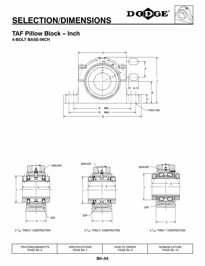
B5--54
SELECTION/DIMENSIONS
TAF Pillow Block -- Inch4-BOLT BASE-INCH
NON-EXP
EXP
A
C
5-7/16″ THRU 7″ CONSTRUCTION
L
E
A
C
EXP
L
NON-EXP
3-7/16″ THRU 5″ CONSTRUCTION
NON-EXP
AL
CEXP
P
J
H
2-7/16″ THRU 3″ CONSTRUCTION
G
M
F BOLT DIAMAX.
MIN.
65°
D
D
B
FEATURES/BENEFITSPAGE B5--2
SPECIFICATIONSPAGE B5--7
HOW TO ORDERPAGE B5--8
NOMENCLATUREPAGE B5--10
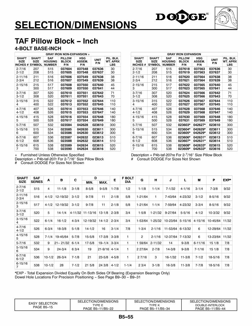
B5--55
SELECTION/DIMENSIONS
TAF Pillow Block -- Inch4-BOLT BASE-INCH
GRAY IRON NON-EXPANSION +SHAFTSIZE
INCHES #
SHAFTSIZE
SYMBOL
SAFHOUSINGNUMBER
PILLOWBLOCKP/N
HSGASSEM.P/N
UNITP/N
PIL. BLK.WT. APRX
LBS2-7/162-1/2
207208
515515
037604037605
037548037548
037636037637
3030
2-11/162-3/4
211212
516516
037606037607
037549037549
037638037639
3838
2-15/163
215300
517517
037608037609
037550037550
037640037641
4544
3-7/163-1/2
307308
520520
037610037611
037551037551
037642037643
7170
3-15/164
315400
522522
037612037613
037552037552
037644037645
110110
4-7/164-1/2
407408
526526
037614037615
037553037553
037646037647
140140
4-15/165
415500
528528
037616037617
037554037554
037648037649
180180
5-7/16 507 532 023584 042628 023610 3005-15/166
515600
534534
023585023586
042630042630
023611023612
300300
6-7/166-1/2
607608
536536
023587023588
042632042632
023613023614
510510
6-15/167
615700
538538
023589023590
042634042634
023615023616
520520
+ Furnished Unless Otherwise SpecifiedDescription = P4b-taf-207r For 2-7/16″ Size Pillow Block
GRAY IRON EXPANSIONSHAFTSIZE
INCHES #
SHAFTSIZE
SYMBOL
SAFHOUSINGNUMBER
PILLOWBLOCKP/N
HSGASSEM.P/N
UNITP/N
PIL. BLK.WT. APRX
LBS2-7/162-1/2
207208
515515
037618037619
037563037563
037636037637
3030
2-11/162-3/4
211212
516516
037620037621
037564037564
037638037639
3838
2-15/163
215300
517517
037622037623
037565037565
037640037641
4544
3-7/163-1/2
307308
520520
037624037625
037566037566
037642037643
7170
3-15/164
315400
522522
037626037627
037567037567
037644037645
110110
4-7/164-1/2
407408
526526
037628037629
037568037568
037646037647
140140
4-15/165
415500
528528
037630037631
037569037569
037648037649
180180
5-7/16 507 532 023603* 042627* 023610 3005-15/166
515600
534534
023604*023605*
042629*042629*
023611023612
300300
6-7/166-1/2
607608
536536
023606*023607*
042631*042631*
023613023614
510510
6-15/167
615700
538538
023608*023609*
042633*042633*
023615023616
520520
Description = P4b-taf-207re For 2-7/16″ Size Pillow Block# Consult DODGE For Sizes Not Shown
# Consult DODGE For Sizes Not Shown
SHAFT SAF A B CD
E F BOLT G H J L M P EXP*SHAFTSIZE
SAFSERIES A B C
MIN. MAX.E F BOLT
DIA G H J L M P EXP*
2-7/162-1/2 515 4 11-1/8 3-1/8 8-5/8 9-5/8 1-7/8 1/2 1-1/8 1-1/4 7-1/32 4-1/16 3-1/4 7-3/8 9/32
2-11/162-3/4 516 4-1/2 12-19/32 3-1/2 9-7/8 11 2-1/8 5/8 1-21/64 1 7-43/64 4-23/32 3-1/2 8-5/16 9/32
2-15/163 517 4-1/2 12-19/32 3-1/2 9-7/8 11 2-1/8 5/8 1-21/64 1-1/4 7-59/64 4-23/32 3-3/4 8-5/16 9/32
3-7/163-1/2 520 5 14-1/4 4-11/32 11-13/16 13-1/8 2-3/8 3/4 1-5/8 1-21/32 9-27/64 5-5/16 4-1/2 10-3/32 9/32
3-15/164 522 6-1/4 16-1/2 4-3/4 12-19/32 14-1/2 2-3/4 3/4 1-53/64 1-25/32 10-23/64 5-15/16 4-15/16 10-45/64 11/32
4-7/164-1/2 526 6-3/4 18-3/8 5-1/8 14-1/2 16 3-1/4 7/8 1-3/4 2-1/16 11-53/64 6-13/32 6 12-29/64 11/32
4-15/165 528 7-1/4 19-45/64 5-7/8 15-5/8 17-3/8 3-3/8 1 2 2-1/16 12-37/64 7-13/32 6 13-23/64 11/32
5-7/16 532 9 21-- 21/32 6-1/4 17-5/8 19--1/4 3-3/4 1 1 59/64 2-11/32 14 9-3/8 6-11/16 15 1/8 7/85-15/166 534 9 24-3/4 6 3/4 19 21-9/16 4-1/4 1 2 27/64 2-7/8 14-3/8 9-3/8 7-1/16 15 1/8 7/8
6-7/166-1/2 536 10-1/2 26-3/4 7-1/8 21 23-5/8 4-5/8 1 2 7/16 3 16-1/32 11-3/8 7-1/2 18-5/16 7/8
6-15/167 538 10-1/2 28 7-1/2 21 5/8 24 3/8 4-1/2 1-1/4 2 3/4 3-1/8 16-3/8 11-3/8 7-7/8 18-5/16 7/8
*EXP - Total Expansion Divided Equally On Both Sides Of Bearing (Expansion Bearings Only)Dowel Hole Locations For Precision Positioning -- See Page B9--30 -- B9--31
SELECTION/DIMENSIONSTYPE E
PAGE B5--11/B5--22
SELECTION/DIMENSIONSTYPE K
PAGE B5--11/B5--34
EASY SELECTIONPAGE B5--15
SELECTION/DIMENSIONSDOUBLE-INTERLOCKPAGE B5--11/B5--44
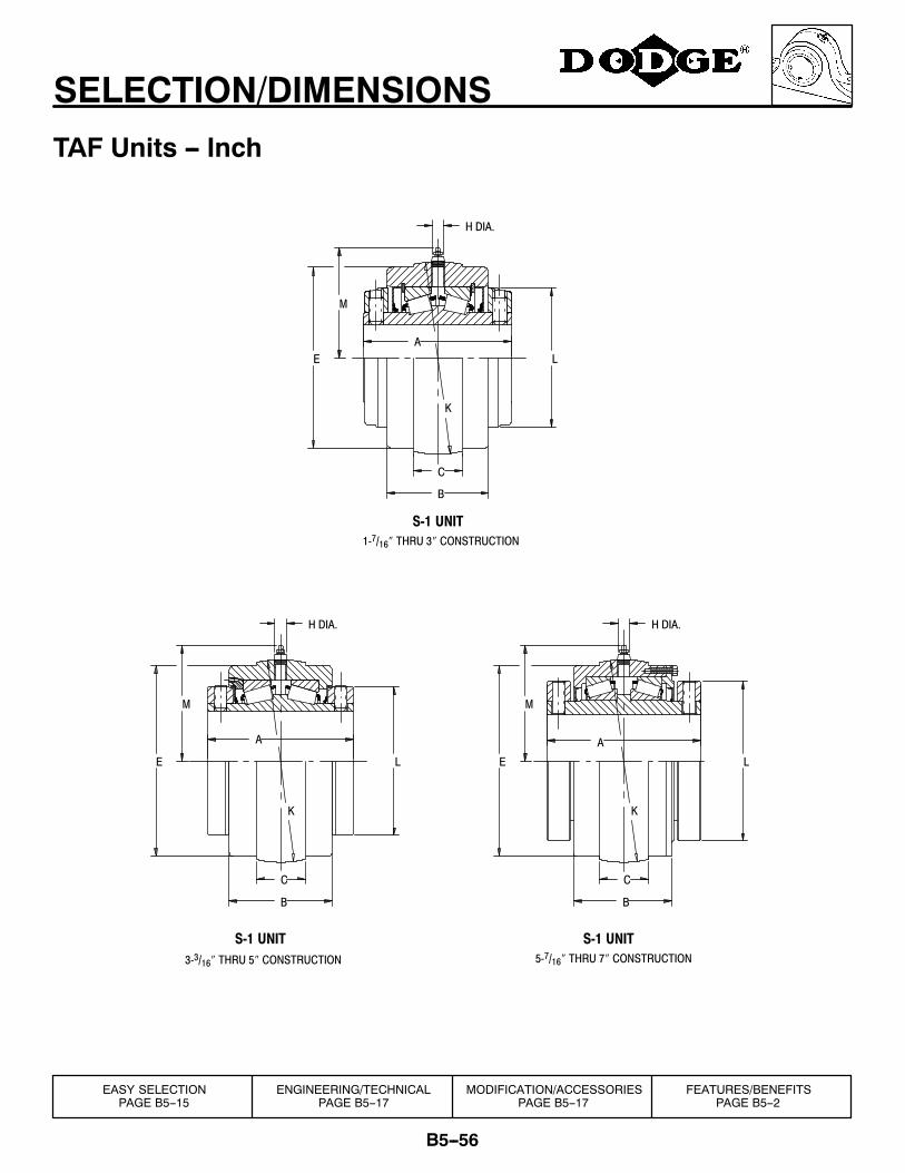
B5--56
SELECTION/DIMENSIONS
TAF Units -- Inch
B
C
K
M
E L
H DIA.
K
C
B
E
M
H DIA.
1-7/16″ THRU 3″ CONSTRUCTION
K
E
M
L
H DIA.
A
C
B
A
L
A
3-3/16″ THRU 5″ CONSTRUCTION 5-7/16″ THRU 7″ CONSTRUCTION
S-1 UNIT
S-1 UNIT S-1 UNIT
EASY SELECTIONPAGE B5--15
ENGINEERING/TECHNICALPAGE B5--17
MODIFICATION/ACCESSORIESPAGE B5--17
FEATURES/BENEFITSPAGE B5--2
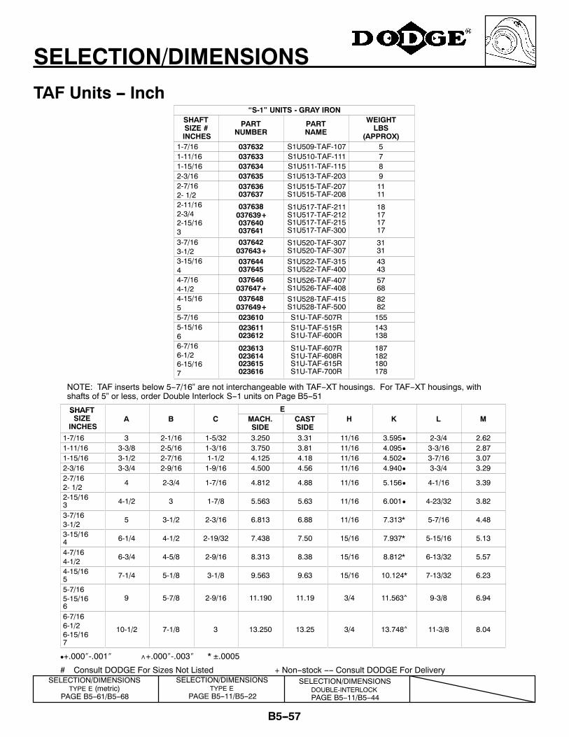
B5--57
SELECTION/DIMENSIONS
TAF Units -- Inch“S-1” UNITS - GRAY IRON
SHAFTSIZE #INCHES
PARTNUMBER
PARTNAME
WEIGHTLBS
(APPROX)1-7/16 037632 S1U509-TAF-107 51-11/16 037633 S1U510-TAF-111 71-15/16 037634 S1U511-TAF-115 82-3/16 037635 S1U513-TAF-203 92-7/162- 1/2
037636037637
S1U515-TAF-207S1U515-TAF-208
1111
2-11/162-3/42-15/163
037638037639+037640037641
S1U517-TAF-211S1U517-TAF-212S1U517-TAF-215S1U517-TAF-300
18171717
3-7/163-1/2
037642037643+
S1U520-TAF-307S1U520-TAF-307
3131
3-15/164
037644037645
S1U522-TAF-315S1U522-TAF-400
4343
4-7/164-1/2
037646037647+
S1U526-TAF-407S1U526-TAF-408
5768
4-15/165
037648037649+
S1U528-TAF-415S1U528-TAF-500
8282
5-7/16 023610 S1U-TAF-507R 1555-15/166
023611023612
S1U-TAF-515RS1U-TAF-600R
143138
6-7/166-1/26-15/167
023613023614023615023616
S1U-TAF-607RS1U-TAF-608RS1U-TAF-615RS1U-TAF-700R
187182180178
NOTE: TAF inserts below 5--7/16” are not interchangeable with TAF--XT housings. For TAF--XT housings, withshafts of 5” or less, order Double Interlock S--1 units on Page B5--51
SHAFT ESHAFTSIZE
INCHESA B C MACH.
SIDECASTSIDE
H K L M
1-7/16 3 2-1/16 1-5/32 3.250 3.31 11/16 3.595D 2-3/4 2.621-11/16 3-3/8 2-5/16 1-3/16 3.750 3.81 11/16 4.095D 3-3/16 2.871-15/16 3-1/2 2-7/16 1-1/2 4.125 4.18 11/16 4.502D 3-7/16 3.072-3/16 3-3/4 2-9/16 1-9/16 4.500 4.56 11/16 4.940D 3-3/4 3.292-7/162- 1/2
4 2-3/4 1-7/16 4.812 4.88 11/16 5.156D 4-1/16 3.39
2-15/163 4-1/2 3 1-7/8 5.563 5.63 11/16 6.001D 4-23/32 3.82
3-7/163-1/2
5 3-1/2 2-3/16 6.813 6.88 11/16 7.313* 5-7/16 4.48
3-15/164 6-1/4 4-1/2 2-19/32 7.438 7.50 15/16 7.937* 5-15/16 5.13
4-7/164-1/2
6-3/4 4-5/8 2-9/16 8.313 8.38 15/16 8.812* 6-13/32 5.57
4-15/165 7-1/4 5-1/8 3-1/8 9.563 9.63 15/16 10.124* 7-13/32 6.23
5-7/165-15/166
9 5-7/8 2-9/16 11.190 11.19 3/4 11.563^ 9-3/8 6.94
6-7/166-1/26-15/167
10-1/2 7-1/8 3 13.250 13.25 3/4 13.748^ 11-3/8 8.04
D+.000″-.001″ ∧+.000″-.003″ * ±.0005
# Consult DODGE For Sizes Not Listed + Non--stock ---- Consult DODGE For DeliverySELECTION/DIMENSIONS
DOUBLE-INTERLOCKPAGE B5--11/B5--44
SELECTION/DIMENSIONSTYPE E
PAGE B5--11/B5--22
SELECTION/DIMENSIONSTYPE E (metric)
PAGE B5--61/B5--68
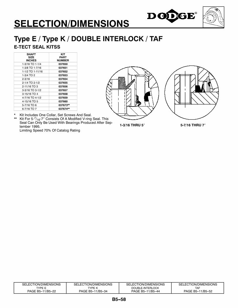
B5--58
SELECTION/DIMENSIONS
Type E / Type K / DOUBLE INTERLOCK / TAFE-TECT SEAL KITSS
SHAFTSIZE
INCHES
KITPART
NUMBER1-3/16 TO 1-1/4 0376501-3/8 TO 1-7/16 0376511-1/2 TO 1-11/16 0376521-3/4 TO 2 0376532-3/16 0376542-1/4 TO 2-1/2 0376552-11/16 TO 3 0376563-3/16 TO 3-1/2 0376573-15/16 TO 4 0376584-7/16 TO 4-1/2 0376594-15/16 TO 5 0376605-7/16 TO 6 037673**6-7/16 TO 7 037674**
* Kit Includes One Collar, Set Screws And Seal.** Kit For 5-7/16-7″ Consists Of A Modified V-ring Seal. This
Seal Can Only Be Used With Bearings Produced After Sep-tember 1995.
� Limiting Speed 70% Of Catalog Rating
SELECTION/DIMENSIONSTYPE E
PAGE B5--11/B5--22
SELECTION/DIMENSIONSTYPE K
PAGE B5--11/B5--34
SELECTION/DIMENSIONSDOUBLE-INTERLOCKPAGE B5--11/B5--44
SELECTION/DIMENSIONSTAF
PAGE B5--11/B5--52
1-3/16 THRU 5″ 5-7/16 THRU 7″
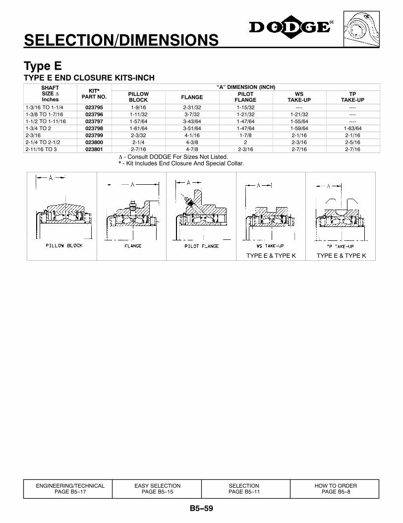
B5--59
SELECTION/DIMENSIONS
Type ETYPE E END CLOSURE KITS-INCH
SHAFT KIT*“A” DIMENSION (INCH)SHAFT
SIZE ∆Inches
KIT*PART NO. PILLOW
BLOCK FLANGE PILOTFLANGE
WSTAKE-UP
TPTAKE-UP
1-3/16 TO 1-1/4 023795 1-9/16 2-31/32 1-15/32 ---- ----1-3/8 TO 1-7/16 023796 1-11/32 3-7/32 1-21/32 1-21/32 ----1-1/2 TO 1-11/16 023797 1-57/64 3-43/64 1-47/64 1-55/64 ----1-3/4 TO 2 023798 1-61/64 3-51/64 1-47/64 1-59/64 1-63/642-3/16 023799 2-3/32 4-1/16 1-7/8 2-1/16 2-1/162-1/4 TO 2-1/2 023800 2-1/4 4-3/8 2 2-3/16 2-5/162-11/16 TO 3 023801 2-7/16 4-7/8 2-3/16 2-7/16 2-7/16
∆ - Consult DODGE For Sizes Not Listed.* - Kit Includes End Closure And Special Collar.
TYPE E & TYPE K TYPE E & TYPE K
SELECTIONPAGE B5--11
EASY SELECTIONPAGE B5--15
ENGINEERING/TECHNICALPAGE B5--17
HOW TO ORDERPAGE B5--8
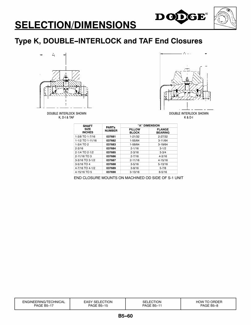
B5--60
SELECTION/DIMENSIONS
Type K, DOUBLE--INTERLOCK and TAF End Closures
K & D-IK, D-I & TAFDOUBLE INTERLOCK SHOWN DOUBLE INTERLOCK SHOWN
SHAFT PARTs“A” DIMENSIONSHAFT
SIZEINCHES
PARTsNUMBER PILLOW
BLOCKFLANGEBEARING
1-3/8 TO 1-7/16 037681 1-21/32 2-27/321-1/2 TO 1-11/16 037682 1-55/64 3-11/641-3/4 TO 2 037683 1-59/64 3-19/642-3/16 037684 2-1/16 3-1/22-1/4 TO 2-1/2 037685 2-3/16 3-3/42-11/16 TO 3 037686 2-7/16 4-3/163-3/16 TO 3-1/2 037687 2-11/16 4-15/163-5/16 TO 4 037688 3-5/16 5-13/164-7/16 TO 4-1/2 037689 3-9/16 5-7/84-15/16 TO 5 037690 3-13/16 6-5/16
END CLOSURE MOUNTS ON MACHINED OD SIDE OF S-1 UNIT
SELECTIONPAGE B5--11
EASY SELECTIONPAGE B5--15
ENGINEERING/TECHNICALPAGE B5--17
HOW TO ORDERPAGE B5--8
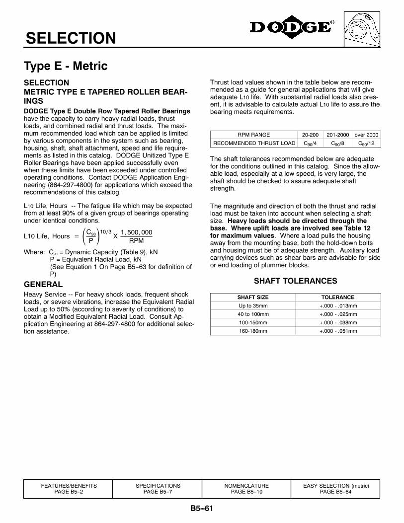
B5--61
SELECTION
Type E - MetricSELECTIONMETRIC TYPE E TAPERED ROLLER BEAR-INGSDODGE Type E Double Row Tapered Roller Bearingshave the capacity to carry heavy radial loads, thrustloads, and combined radial and thrust loads. The maxi-mum recommended load which can be applied is limitedby various components in the system such as bearing,housing, shaft, shaft attachment, speed and life require-ments as listed in this catalog. DODGE Unitized Type ERoller Bearings have been applied successfully evenwhen these limits have been exceeded under controlledoperating conditions. Contact DODGE Application Engi-neering (864-297-4800) for applications which exceed therecommendations of this catalog.
L10 Life, Hours -- The fatigue life which may be expectedfrom at least 90% of a given group of bearings operatingunder identical conditions.
L10 Life, Hours = C90
P10∕3 X 1, 500, 000
RPM
Where: C90 = Dynamic Capacity (Table 9), kNP = Equivalent Radial Load, kN(See Equation 1 On Page B5--63 for definition ofP)
GENERALHeavy Service -- For heavy shock loads, frequent shockloads, or severe vibrations, increase the Equivalent RadialLoad up to 50% (according to severity of conditions) toobtain a Modified Equivalent Radial Load. Consult Ap-plication Engineering at 864-297-4800 for additional selec-tion assistance.
Thrust load values shown in the table below are recom-mended as a guide for general applications that will giveadequate L10 life. With substantial radial loads also pres-ent, it is advisable to calculate actual L10 life to assure thebearing meets requirements.
RPM RANGE 20-200 201-2000 over 2000
RECOMMENDED THRUST LOAD C90/4 C90/8 C90/12
The shaft tolerances recommended below are adequatefor the conditions outlined in this catalog. Since the allow-able load, especially at a low speed, is very large, theshaft should be checked to assure adequate shaftstrength.
The magnitude and direction of both the thrust and radialload must be taken into account when selecting a shaftsize. Heavy loads should be directed through thebase. Where uplift loads are involved see Table 12for maximum values. Where a load pulls the housingaway from the mounting base, both the hold-down boltsand housing must be of adequate strength. Auxiliary loadcarrying devices such as shear bars are advisable for sideor end loading of plummer blocks.
SHAFT TOLERANCES
SHAFT SIZE TOLERANCE
Up to 35mm +.000 - .013mm
40 to 100mm +.000 - .025mm
100-150mm +.000 - .038mm
160-180mm +.000 - .051mm
FEATURES/BENEFITSPAGE B5--2
SPECIFICATIONSPAGE B5--7
NOMENCLATUREPAGE B5--10
EASY SELECTION (metric)PAGE B5--64
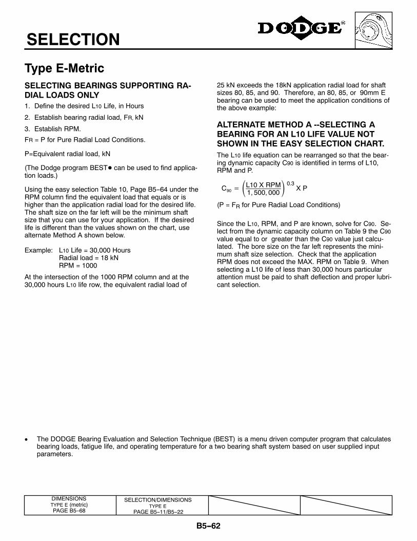
B5--62
SELECTION
Type E-MetricSELECTING BEARINGS SUPPORTING RA-DIAL LOADS ONLY1. Define the desired L10 Life, in Hours
2. Establish bearing radial load, FR, kN
3. Establish RPM.
FR = P for Pure Radial Load Conditions.
P=Equivalent radial load, kN
(The Dodge program BESTD can be used to find applica-tion loads.)
Using the easy selection Table 10, Page B5--64 under theRPM column find the equivalent load that equals or ishigher than the application radial load for the desired life.The shaft size on the far left will be the minimum shaftsize that you can use for your application. If the desiredlife is different than the values shown on the chart, usealternate Method A shown below.
Example: L10 Life = 30,000 HoursRadial load = 18 kNRPM = 1000
At the intersection of the 1000 RPM column and at the30,000 hours L10 life row, the equivalent radial load of
25 kN exceeds the 18kN application radial load for shaftsizes 80, 85, and 90. Therefore, an 80, 85, or 90mm Ebearing can be used to meet the application conditions ofthe above example:
ALTERNATE METHOD A --SELECTING ABEARING FOR AN L10 LIFE VALUE NOTSHOWN IN THE EASY SELECTION CHART.The L10 life equation can be rearranged so that the bear-ing dynamic capacity C90 is identified in terms of L10,RPM and P.
C90 = L10 X RPM1, 500, 000
0.3 X P
(P = FR for Pure Radial Load Conditions)
Since the L10, RPM, and P are known, solve for C90. Se-lect from the dynamic capacity column on Table 9 the C90value equal to or greater than the C90 value just calcu-lated. The bore size on the far left represents the mini-mum shaft size selection. Check that the applicationRPM does not exceed the MAX. RPM on Table 9. Whenselecting a L10 life of less than 30,000 hours particularattention must be paid to shaft deflection and proper lubri-cant selection.
¯ The DODGE Bearing Evaluation and Selection Technique (BEST) is a menu driven computer program that calculatesbearing loads, fatigue life, and operating temperature for a two bearing shaft system based on user supplied inputparameters.
SELECTION/DIMENSIONSTYPE E
PAGE B5--11/B5--22
DIMENSIONSTYPE E (metric)PAGE B5--68
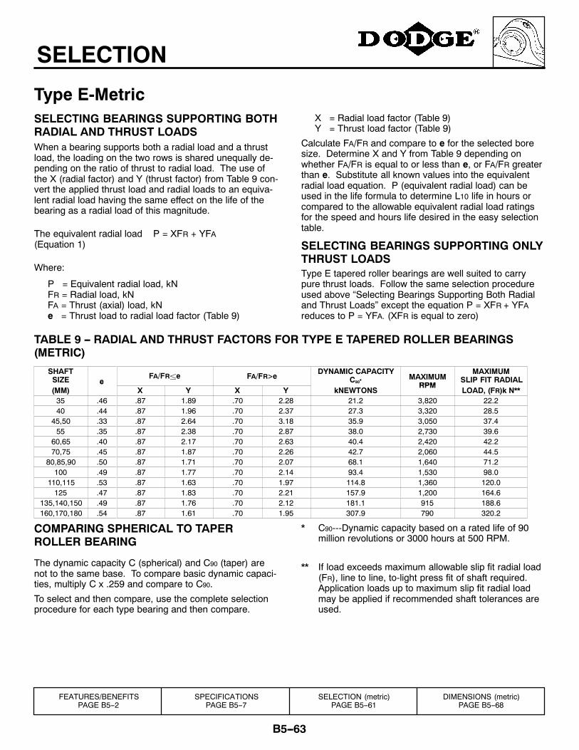
B5--63
SELECTION
Type E-MetricSELECTING BEARINGS SUPPORTING BOTHRADIAL AND THRUST LOADSWhen a bearing supports both a radial load and a thrustload, the loading on the two rows is shared unequally de-pending on the ratio of thrust to radial load. The use ofthe X (radial factor) and Y (thrust factor) from Table 9 con-vert the applied thrust load and radial loads to an equiva-lent radial load having the same effect on the life of thebearing as a radial load of this magnitude.
The equivalent radial load P = XFR + YFA(Equation 1)
Where:
P = Equivalent radial load, kNFR = Radial load, kNFA = Thrust (axial) load, kNe = Thrust load to radial load factor (Table 9)
X = Radial load factor (Table 9)Y = Thrust load factor (Table 9)
Calculate FA/FR and compare to e for the selected boresize. Determine X and Y from Table 9 depending onwhether FA/FR is equal to or less than e, or FA/FR greaterthan e. Substitute all known values into the equivalentradial load equation. P (equivalent radial load) can beused in the life formula to determine L10 life in hours orcompared to the allowable equivalent radial load ratingsfor the speed and hours life desired in the easy selectiontable.
SELECTING BEARINGS SUPPORTING ONLYTHRUST LOADSType E tapered roller bearings are well suited to carrypure thrust loads. Follow the same selection procedureused above “Selecting Bearings Supporting Both Radialand Thrust Loads” except the equation P = XFR + YFAreduces to P = YFA. (XFR is equal to zero)
TABLE 9 -- RADIAL AND THRUST FACTORS FOR TYPE E TAPERED ROLLER BEARINGS(METRIC)
SHAFTSIZE e
FA/FR±e FA/FR>e DYNAMIC CAPACITYC90*
MAXIMUMRPM
MAXIMUMSLIP FIT RADIAL
(MM)e
X Y X Y kNEWTONSRPM
LOAD, (FR)k N**35 .46 .87 1.89 .70 2.28 21.2 3,820 22.240 .44 .87 1.96 .70 2.37 27.3 3,320 28.5
45,50 .33 .87 2.64 .70 3.18 35.9 3,050 37.455 .35 .87 2.38 .70 2.87 38.0 2,730 39.6
60,65 .40 .87 2.17 .70 2.63 40.4 2,420 42.270,75 .45 .87 1.87 .70 2.26 42.7 2,060 44.5
80,85,90 .50 .87 1.71 .70 2.07 68.1 1,640 71.2100 .49 .87 1.77 .70 2.14 93.4 1,530 98.0
110,115 .53 .87 1.63 .70 1.97 114.8 1,360 120.0125 .47 .87 1.83 .70 2.21 157.9 1,200 164.6
135,140,150 .49 .87 1.76 .70 2.12 181.1 915 188.6160,170,180 .54 .87 1.61 .70 1.95 307.9 790 320.2
COMPARING SPHERICAL TO TAPERROLLER BEARING
The dynamic capacity C (spherical) and C90 (taper) arenot to the same base. To compare basic dynamic capaci-ties, multiply C x .259 and compare to C90.
To select and then compare, use the complete selectionprocedure for each type bearing and then compare.
* C90---Dynamic capacity based on a rated life of 90million revolutions or 3000 hours at 500 RPM.
** If load exceeds maximum allowable slip fit radial load(FR), line to line, to-light press fit of shaft required.Application loads up to maximum slip fit radial loadmay be applied if recommended shaft tolerances areused.
FEATURES/BENEFITSPAGE B5--2
SPECIFICATIONSPAGE B5--7
SELECTION (metric)PAGE B5--61
DIMENSIONS (metric)PAGE B5--68
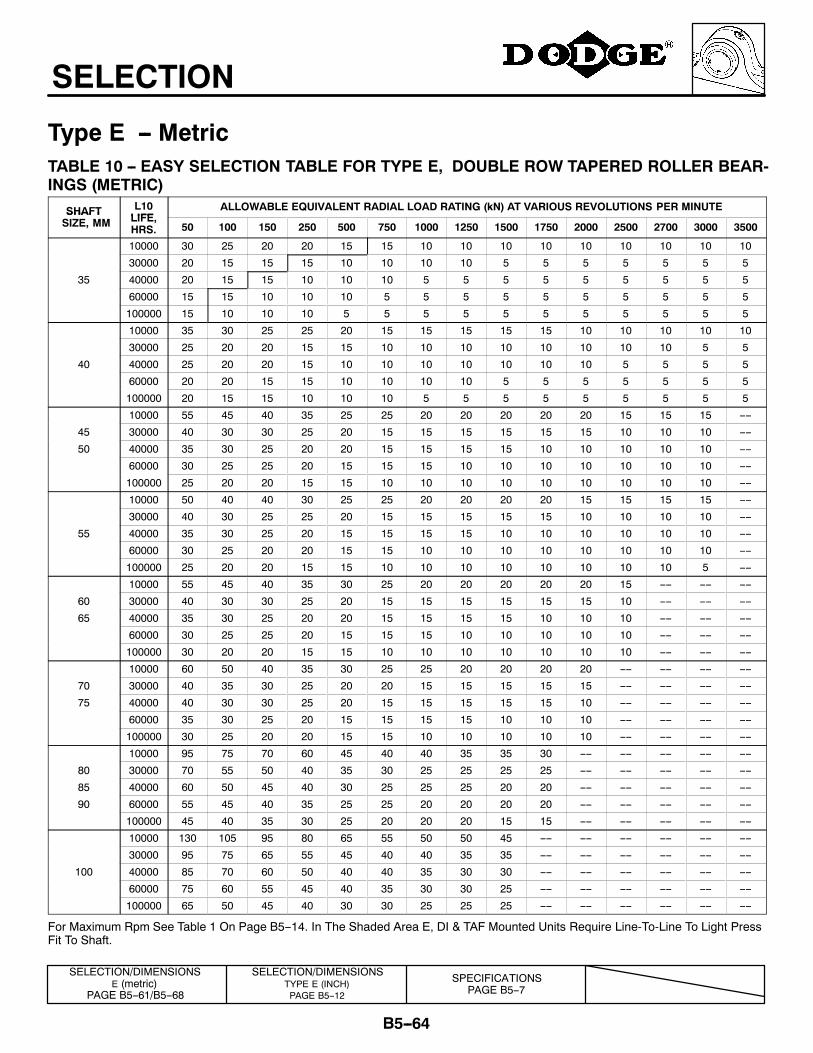
B5--64
SELECTION
Type E -- MetricTABLE 10 -- EASY SELECTION TABLE FOR TYPE E, DOUBLE ROW TAPERED ROLLER BEAR-INGS (METRIC)
SHAFT L10LIFE
ALLOWABLE EQUIVALENT RADIAL LOAD RATING (kN) AT VARIOUS REVOLUTIONS PER MINUTESHAFTSIZE, MM LIFE,
HRS. 50 100 150 250 500 750 1000 1250 1500 1750 2000 2500 2700 3000 3500
10000 30 25 20 20 15 15 10 10 10 10 10 10 10 10 10
30000 20 15 15 15 10 10 10 10 5 5 5 5 5 5 5
35 40000 20 15 15 10 10 10 5 5 5 5 5 5 5 5 5
60000 15 15 10 10 10 5 5 5 5 5 5 5 5 5 5
100000 15 10 10 10 5 5 5 5 5 5 5 5 5 5 5
10000 35 30 25 25 20 15 15 15 15 15 10 10 10 10 10
30000 25 20 20 15 15 10 10 10 10 10 10 10 10 5 5
40 40000 25 20 20 15 10 10 10 10 10 10 10 5 5 5 5
60000 20 20 15 15 10 10 10 10 5 5 5 5 5 5 5
100000 20 15 15 10 10 10 5 5 5 5 5 5 5 5 5
10000 55 45 40 35 25 25 20 20 20 20 20 15 15 15 ----
45 30000 40 30 30 25 20 15 15 15 15 15 15 10 10 10 ----
50 40000 35 30 25 20 20 15 15 15 15 10 10 10 10 10 ----
60000 30 25 25 20 15 15 15 10 10 10 10 10 10 10 ----
100000 25 20 20 15 15 10 10 10 10 10 10 10 10 10 ----
10000 50 40 40 30 25 25 20 20 20 20 15 15 15 15 ----
30000 40 30 25 25 20 15 15 15 15 15 10 10 10 10 ----
55 40000 35 30 25 20 15 15 15 15 10 10 10 10 10 10 ----
60000 30 25 20 20 15 15 10 10 10 10 10 10 10 10 ----
100000 25 20 20 15 15 10 10 10 10 10 10 10 10 5 ----
10000 55 45 40 35 30 25 20 20 20 20 20 15 ---- ---- ----
60 30000 40 30 30 25 20 15 15 15 15 15 15 10 ---- ---- ----
65 40000 35 30 25 20 20 15 15 15 15 10 10 10 ---- ---- ----
60000 30 25 25 20 15 15 15 10 10 10 10 10 ---- ---- ----
100000 30 20 20 15 15 10 10 10 10 10 10 10 ---- ---- ----
10000 60 50 40 35 30 25 25 20 20 20 20 ---- ---- ---- ----
70 30000 40 35 30 25 20 20 15 15 15 15 15 ---- ---- ---- ----
75 40000 40 30 30 25 20 15 15 15 15 15 10 ---- ---- ---- ----
60000 35 30 25 20 15 15 15 15 10 10 10 ---- ---- ---- ----
100000 30 25 20 20 15 15 10 10 10 10 10 ---- ---- ---- ----
10000 95 75 70 60 45 40 40 35 35 30 ---- ---- ---- ---- ----
80 30000 70 55 50 40 35 30 25 25 25 25 ---- ---- ---- ---- ----
85 40000 60 50 45 40 30 25 25 25 20 20 ---- ---- ---- ---- ----
90 60000 55 45 40 35 25 25 20 20 20 20 ---- ---- ---- ---- ----
100000 45 40 35 30 25 20 20 20 15 15 ---- ---- ---- ---- ----
10000 130 105 95 80 65 55 50 50 45 ---- ---- ---- ---- ---- ----
30000 95 75 65 55 45 40 40 35 35 ---- ---- ---- ---- ---- ----
100 40000 85 70 60 50 40 40 35 30 30 ---- ---- ---- ---- ---- ----
60000 75 60 55 45 40 35 30 30 25 ---- ---- ---- ---- ---- ----
100000 65 50 45 40 30 30 25 25 25 ---- ---- ---- ---- ---- ----
For Maximum Rpm See Table 1 On Page B5--14. In The Shaded Area E, DI & TAF Mounted Units Require Line-To-Line To Light PressFit To Shaft.
SELECTION/DIMENSIONSTYPE E (INCH)PAGE B5--12
SELECTION/DIMENSIONSE (metric)
PAGE B5--61/B5--68
SPECIFICATIONSPAGE B5--7
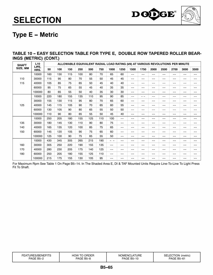
B5--65
SELECTION
Type E -- Metric
TABLE 10 -- EASY SELECTION TABLE FOR TYPE E, DOUBLE ROW TAPERED ROLLER BEAR-INGS (METRIC) (CONT.)
SHAFT L10LIFE
ALLOWABLE EQUIVALENT RADIAL LOAD RATING (kN) AT VARIOUS REVOLUTIONS PER MINUTESHAFTSIZE, MM LIFE,
HRS. 50 100 150 250 500 750 1000 1250 1500 1750 2000 2500 2700 3000 3500
10000 160 130 115 100 80 70 65 60 ---- ---- ---- ---- ---- ---- ----
110 30000 115 95 80 70 55 50 45 45 ---- ---- ---- ---- ---- ---- ----
115 40000 105 85 75 65 50 45 40 40 ---- ---- ---- ---- ---- ---- ----
60000 95 75 65 55 45 40 35 35 ---- ---- ---- ---- ---- ---- ----
100000 80 65 55 50 40 35 30 30 ---- ---- ---- ---- ---- ---- ----
10000 220 180 155 135 110 95 90 85 ---- -- -- ---- ---- ---- ---- ----
30000 155 130 115 95 80 70 65 60 ---- ---- ---- ---- ---- ---- ----
125 40000 145 115 105 90 70 65 60 55 ---- ---- ---- ---- ---- ---- ----
60000 130 105 90 80 65 55 50 50 ---- ---- ---- ---- ---- ---- ----
100000 110 90 80 65 55 50 45 40 ---- ---- ---- ---- ---- ---- ----
10000 250 205 180 155 125 110 100 ---- ---- ---- ---- ---- ---- ---- ----
135 30000 180 145 130 110 90 80 75 ---- ---- ---- ---- ---- ---- ---- ----
140 40000 165 135 120 100 85 75 65 ---- ---- ---- ---- ---- ---- ---- ----
150 60000 145 120 105 90 75 65 60 ---- ---- ---- ---- ---- ---- ---- ----
100000 125 100 90 75 65 55 50 ---- ---- ---- ---- ---- ---- ---- ----
10000 430 345 305 265 215 190 -- -- ---- ---- ---- ---- ---- ---- ---- ----
160 30000 305 250 220 190 155 135 ---- ---- ---- ---- ---- ---- ---- ---- ----
170 40000 280 230 205 175 140 125 ---- ---- ---- ---- ---- ---- ---- ---- ----
180 60000 250 205 180 155 125 110 ---- ---- ---- ---- ---- ---- ---- ---- ----
100000 215 175 155 130 105 95 ---- ---- ---- ---- ---- ---- ---- ---- ----
For Maximum Rpm See Table 1 On Page B5--14. In The Shaded Area E, DI & TAF Mounted Units Require Line-To-Line To Light PressFit To Shaft.
HOW TO ORDERPAGE B5--8
NOMENCLATUREPAGE B5--10
SELECTION (metric)PAGE B5--61
FEATURES/BENEFITSPAGE B5--2
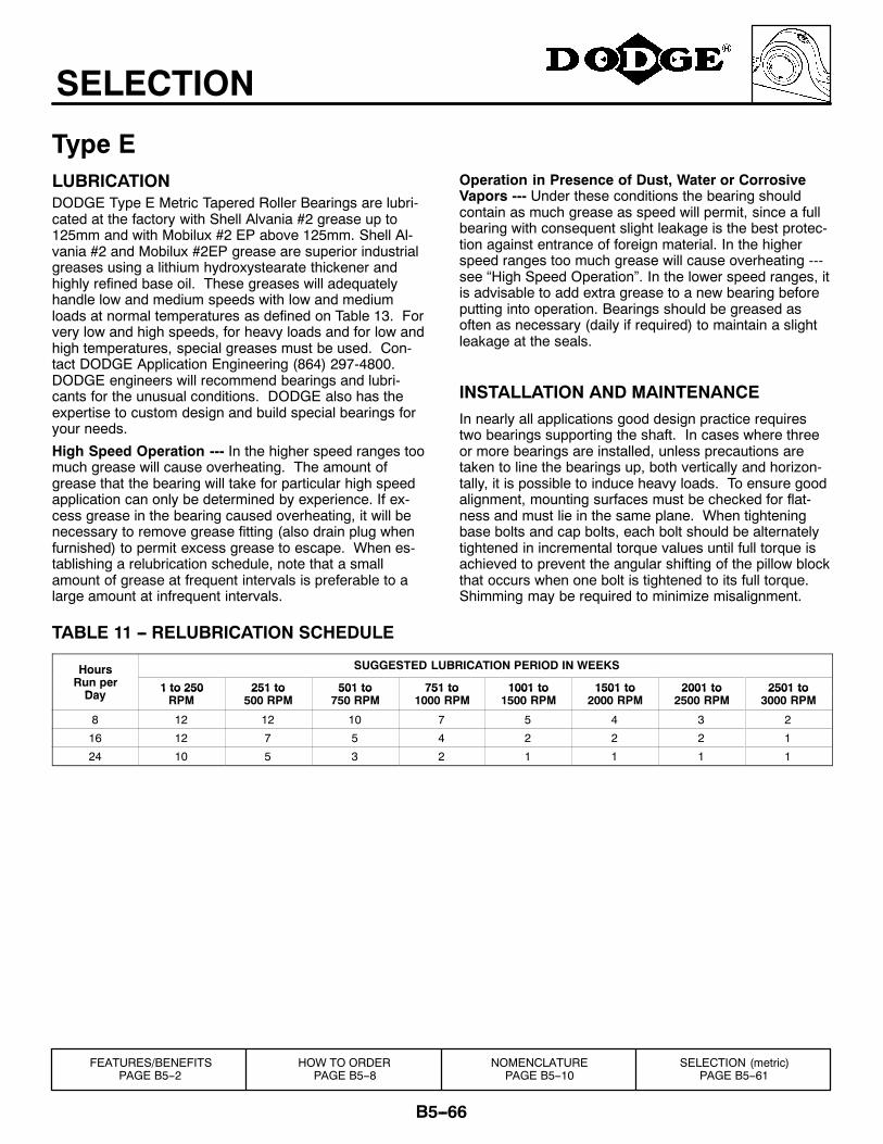
B5--66
SELECTION
Type ELUBRICATIONDODGE Type E Metric Tapered Roller Bearings are lubri-cated at the factory with Shell Alvania #2 grease up to125mm and with Mobilux #2 EP above 125mm. Shell Al-vania #2 and Mobilux #2EP grease are superior industrialgreases using a lithium hydroxystearate thickener andhighly refined base oil. These greases will adequatelyhandle low and medium speeds with low and mediumloads at normal temperatures as defined on Table 13. Forvery low and high speeds, for heavy loads and for low andhigh temperatures, special greases must be used. Con-tact DODGE Application Engineering (864) 297-4800.DODGE engineers will recommend bearings and lubri-cants for the unusual conditions. DODGE also has theexpertise to custom design and build special bearings foryour needs.
High Speed Operation --- In the higher speed ranges toomuch grease will cause overheating. The amount ofgrease that the bearing will take for particular high speedapplication can only be determined by experience. If ex-cess grease in the bearing caused overheating, it will benecessary to remove grease fitting (also drain plug whenfurnished) to permit excess grease to escape. When es-tablishing a relubrication schedule, note that a smallamount of grease at frequent intervals is preferable to alarge amount at infrequent intervals.
Operation in Presence of Dust, Water or CorrosiveVapors --- Under these conditions the bearing shouldcontain as much grease as speed will permit, since a fullbearing with consequent slight leakage is the best protec-tion against entrance of foreign material. In the higherspeed ranges too much grease will cause overheating ---see “High Speed Operation”. In the lower speed ranges, itis advisable to add extra grease to a new bearing beforeputting into operation. Bearings should be greased asoften as necessary (daily if required) to maintain a slightleakage at the seals.
INSTALLATION AND MAINTENANCEIn nearly all applications good design practice requirestwo bearings supporting the shaft. In cases where threeor more bearings are installed, unless precautions aretaken to line the bearings up, both vertically and horizon-tally, it is possible to induce heavy loads. To ensure goodalignment, mounting surfaces must be checked for flat-ness and must lie in the same plane. When tighteningbase bolts and cap bolts, each bolt should be alternatelytightened in incremental torque values until full torque isachieved to prevent the angular shifting of the pillow blockthat occurs when one bolt is tightened to its full torque.Shimming may be required to minimize misalignment.
TABLE 11 -- RELUBRICATION SCHEDULE
Hours SUGGESTED LUBRICATION PERIOD IN WEEKSHoursRun perDay
1 to 250 251 to 501 to 751 to 1001 to 1501 to 2001 to 2501 toDay
1 to 250RPM
251 to500 RPM
501 to750 RPM
751 to1000 RPM
1001 to1500 RPM
1501 to2000 RPM
2001 to2500 RPM
2501 to3000 RPM
8 12 12 10 7 5 4 3 2
16 12 7 5 4 2 2 2 1
24 10 5 3 2 1 1 1 1
HOW TO ORDERPAGE B5--8
NOMENCLATUREPAGE B5--10
SELECTION (metric)PAGE B5--61
FEATURES/BENEFITSPAGE B5--2
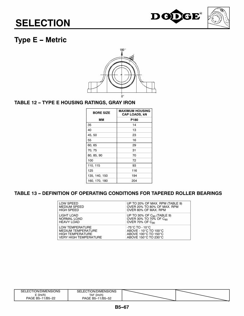
B5--67
SELECTION
Type E -- Metric180_
0°
TABLE 12 -- TYPE E HOUSING RATINGS, GRAY IRON
BORE SIZE MAXIMUM HOUSINGCAP LOADS, kN
MM P180
35 14
40 13
45, 50 23
55 16
60, 65 29
70, 75 31
80, 85, 90 70
100 72
110, 115 93
125 116
135, 140, 150 194
160, 170, 180 204
TABLE 13 -- DEFINITION OF OPERATING CONDITIONS FOR TAPERED ROLLER BEARINGS
LOW SPEEDMEDIUM SPEEDHIGH SPEED
UP TO 20% OF MAX. RPM (TABLE 9)OVER 20% TO 80% OF MAX. RPMOVER 80% OF MAX. RPM
LIGHT LOADNORMAL LOADHEAVY LOAD
UP TO 30% OF C90 (TABLE 9)OVER 30% TO 70% OF C90OVER 70% OF C90
LOW TEMPERATUREMEDIUM TEMPERATUREHIGH TEMPERATUREVERY HIGH TEMPERATURE
-75°C TO - 10°CABOVE - 10°C TO 100°CABOVE 100°C TO 150°CABOVE 150°C TO 230°C
SELECTION/DIMENSIONSTAF (inch)
PAGE B5--11/B5--52
SELECTION/DIMENSIONSE (inch)
PAGE B5--11/B5--22
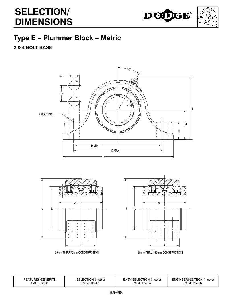
B5--68
SELECTION/DIMENSIONS
Type E -- Plummer Block -- Metric2 & 4 BOLT BASE
M
H
J1
J L
80mm THRU 125mm CONSTRUCTION
A
C
F BOLT DIA.
G
C
35mm THRU 75mm CONSTRUCTION
A
J L
B
D MAX
D MIN
30°
E
FEATURES/BENEFITSPAGE B5--2
SELECTION (metric)PAGE B5--61
EASY SELECTION (metric)PAGE B5--64
ENGINEERING/TECH (metric)PAGE B5--66
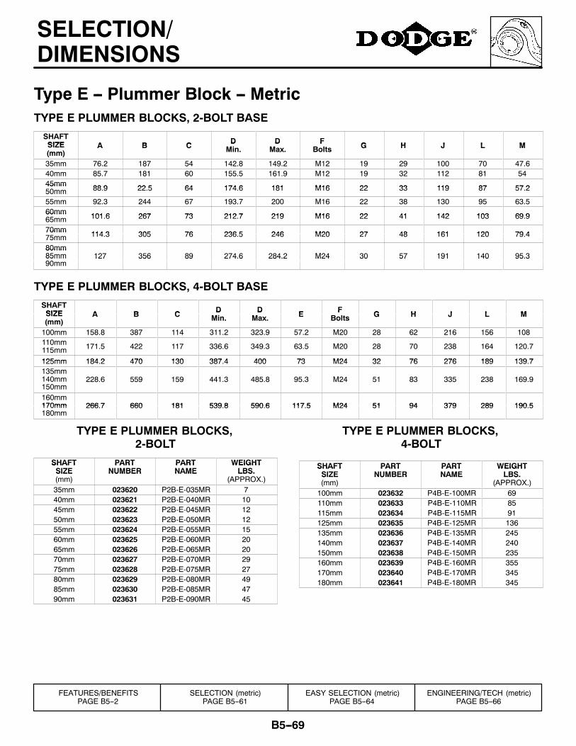
B5--69
SELECTION/DIMENSIONS
Type E -- Plummer Block -- MetricTYPE E PLUMMER BLOCKS, 2-BOLT BASE
SHAFTSIZE A B C D D F G H J L MSIZE(mm)
A B C DMin.
DMax.
FBolts G H J L M
35mm 76.2 187 54 142.8 149.2 M12 19 29 100 70 47.640mm 85.7 181 60 155.5 161.9 M12 19 32 112 81 5445mm 88 9 22 5 64 174 6 181 M16 22 33 119 87 57 245mm50mm 88.9 22.5 64 174.6 181 M16 22 33 119 87 57.2
55mm 92.3 244 67 193.7 200 M16 22 38 130 95 63.560mm 101 6 267 73 212 7 219 M16 22 41 142 103 69 960mm65mm 101.6 267 73 212.7 219 M16 22 41 142 103 69.9
70mm 114 3 305 76 236 5 246 M20 27 48 161 120 79 470mm75mm 114.3 305 76 236.5 246 M20 27 48 161 120 79.4
80mm80mm85mm90
127 356 89 274.6 284.2 M24 30 57 191 140 95.385mm90mm
127 356 89 274.6 284.2 M24 30 57 191 140 95.3
TYPE E PLUMMER BLOCKS, 4-BOLT BASE
SHAFTSIZE A B C D D E F G H J L MSIZE(mm)
A B C DMin.
DMax. E F
Bolts G H J L M
100mm 158.8 387 114 311.2 323.9 57.2 M20 28 62 216 156 108110mm115mm 171.5 422 117 336.6 349.3 63.5 M20 28 70 238 164 120.7
125mm 184 2 470 130 387 4 400 73 M24 32 76 276 189 139 7125mm 184.2 470 130 387.4 400 73 M24 32 76 276 189 139.7135mm140mm150mm
228.6 559 159 441.3 485.8 95.3 M24 51 83 335 238 169.9
160mm170mm 266 7 660 181 539 8 590 6 117 5 M24 51 94 379 289 190 5170mm180mm
266.7 660 181 539.8 590.6 117.5 M24 51 94 379 289 190.5
TYPE E PLUMMER BLOCKS,2-BOLT
SHAFT PART PART WEIGHTSHAFTSIZE
PARTNUMBER
PARTNAME
WEIGHTLBS.SIZE
(mm)NUMBER NAME LBS.
(APPROX.)35mm 023620 P2B-E-035MR 740mm 023621 P2B-E-040MR 1045mm 023622 P2B-E-045MR 1250mm 023623 P2B-E-050MR 1255mm 023624 P2B-E-055MR 1560mm 023625 P2B-E-060MR 2065mm 023626 P2B-E-065MR 2070mm 023627 P2B-E-070MR 2975mm 023628 P2B-E-075MR 2780mm 023629 P2B-E-080MR 4985mm 023630 P2B-E-085MR 4790mm 023631 P2B-E-090MR 45
TYPE E PLUMMER BLOCKS,4-BOLT
SHAFT PART PART WEIGHTSHAFTSIZE
PARTNUMBER
PARTNAME
WEIGHTLBS.SIZE
(mm)NUMBER NAME LBS.
(APPROX.)100mm 023632 P4B-E-100MR 69110mm 023633 P4B-E-110MR 85115mm 023634 P4B-E-115MR 91125mm 023635 P4B-E-125MR 136135mm 023636 P4B-E-135MR 245140mm 023637 P4B-E-140MR 240150mm 023638 P4B-E-150MR 235160mm 023639 P4B-E-160MR 355170mm 023640 P4B-E-170MR 345180mm 023641 P4B-E-180MR 345
FEATURES/BENEFITSPAGE B5--2
SELECTION (metric)PAGE B5--61
EASY SELECTION (metric)PAGE B5--64
ENGINEERING/TECH (metric)PAGE B5--66

B5--70
NOTES