Embed Size (px)
Citation preview

Lei WangSchool of Energy Resources,
China University of Geosciences,
Beijing 100083, China
Xiaodong WangSchool of Energy Resources,
China University of Geosciences,
Beijing 100083, China
Type Curves Analysis forAsymmetrically Fractured WellsIn this paper, a new constant rate solution for asymmetrically fractured wells was pro-posed to analyze the effect of fracture asymmetry on type curves. Calculative resultsshowed that for a small wellbore storage coefficient or for the low fracture conductivity,the effect of fracture asymmetry on early flow was very strong. The existence of thefracture asymmetry would cause bigger pressure depletion and make the starting time oflinear flow occur earlier. Then, new type curves were established for different fractureasymmetry factor and different fracture conductivity. It was shown that a bigger fractureasymmetry factor and low fracture conductivity would prolong the time of wellbore stor-age effects. Therefore, to reduce wellbore storage effects, it was essential to keep higherfracture conductivity and fracture symmetry during the hydraulic fracturing design.Finally, a case example is performed to demonstrate the methodology of new type curvesanalysis and its validation for calculating important formation parameters.[DOI: 10.1115/1.4025712]
Keywords: asymmetrically fractured wells, fracture conductivity, type curves, fractureasymmetry factor, formation parameters
1 Introduction
During the last few decades, a number of well test analysismethods of fractured wells have been proposed [1–4] in the deter-mination of formation properties. Gringarten [5] made an extraor-dinary contribution to the development of transient pressureanalysis and type curves analysis of fractured wells. To considerfracture conductivity effects, a semi-analytical solution and ananalytical solution [6,7] for a vertical fractured well were pre-sented. Later several authors [8–21] applied the solutions tothe analysis of productivity and well test data for fractured wells.The previous theoretical analysis of fractured wells is based onthe same assumption postulating a symmetrically homogeneousfracture. However, actual fractures are asymmetric and there areonly a few papers at present researching asymmetric fractures.
Crawford and Landrum [22] first studied the problem of frac-ture asymmetry, but did not draw meaningful conclusions. Until1979 the effect of fracture asymmetry on the pressure behavior offractured wells at constant rate was discussed by Narasimhan andPlen [23]. Later, Bennet [24] briefly analyzed the influence of thefracture asymmetry on production. However, all these authorsstudied asymmetric fracture by means of numerical simulationmethods.
Resurreic~ao and Fernando [25] obtained a semi-analytical solu-tion in real space under the constant pressure condition. Theyfound that in the process of the flow of fluid, the reciprocal of ratewould be seriously affected by asymmetry factor when fractureasymmetry factor as� 0.8 and the impact would be greater whenas¼ 1.
Rodriguez et al. [26] established a new semi-analytical modelof finite conductivity asymmetric fracture using Green’s Func-tions, and obtained a semi-analytical solution under the constantrate condition. According to the presented solution, he found thecurves of CfDpwD/(1þ 3as
2) versus CfDtD1/2/(1þ 3as
2) wouldshow a linear relationship in the Cartesian coordinate system, andthe intercept bD(as, CfD) is a function of dimensionless conductiv-ity and asymmetry factor.
Berumen et al. [27] proposed constant rate solutions for a frac-tured well with an asymmetric fracture by employing numerical
simulation methods. And then, he made a series of type curves ofthe ratio of pressure and pressure derivative under different as:log–log curves of pD/(2tDpD
0) versus tD (1þ as) 2CfD2. Since they
were numerically solved, the results had a certain error and theapplication of the curves was not given by the authors.
Recently, Tiab et al. [16] reported an interesting paper, in whichTiab’s direct synthesis (TDS) technique was applied to the bilin-ear flow model and linear flow model to calculate dimensionlessconductivity and asymmetry factor. Meanwhile a linear pressureequation which was simple and practical considering both fractureconductivity and asymmetry factor was developed by means ofregression analysis method.
However, their models proposed by the authors above can’t beapplied to well test analysis without considering the wellbore stor-age and skin effects. The objective of this paper is to establish anew model for well test analysis of a finite conductivity asymmet-ric fracture including the wellbore storage and skin effects. Newsolutions for asymmetrically fractured wells under the constantrate condition are presented using Laplace transform and pointsource integral methods. Compared to the previous solutions[25–27], the new solution has several advantages. First of all, thenew solution is obtained in Laplace space, so it not need to scattertime, further reducing the amount of computation and improvingthe computational efficiency; Second, a constant pressure solutioncan be calculated directly from a constant rate solution and thirdlyit is convenient for us to add the wellbore storage effect into theconstant rate solution.
2 Pseudolinear Flow Model
2.1 Define Dimensionless. Dimensionless pressure, dimen-sionless rate, dimensionless time, dimensionless conductivity isdefined as follows [12,16,28]
pwD ¼kh
141:2qlBDpw
tD ¼0:0002637kt
/lctx2f
CfD ¼kfwf
kxf
Contributed by the Petroleum Division of ASME for publication in the JOURNAL
OF ENERGY RESOURCES TECHNOLOGY. Manuscript received August 29, 2012; finalmanuscript received September 28, 2013; published online November 26, 2013.Assoc. Editor: Arash Dahi Taleghani.
Journal of Energy Resources Technology JUNE 2014, Vol. 136 / 023101-1Copyright VC 2014 by ASME
Downloaded From: http://energyresources.asmedigitalcollection.asme.org/ on 09/21/2014 Terms of Use: http://asme.org/terms

2.2 Pseudolinear Flow Model Under Constant RateCondition. Cinco and Meng [29] developed a pseudolinear flowsolution for symmetrically fractured wells. According to hismethod, a pseudolinear solution for asymmetrically fracturedwells in Laplace domain was given as [26]
~pwD ¼
ffiffiffiffiffiffiffiffi2p2
CfD
sðs�5=4Þ
�tanh ð1þ asÞs1=4
ffiffiffiffiffiffiffiffi2
CfD
r� �þ tanh ð1� asÞs1=4
ffiffiffiffiffiffiffiffi2
CfD
r� ���1
(1)
When tD is small (large s), Eq. (1) can be simplified as
~pwD ¼
ffiffiffiffiffiffiffiffi2p2
CfD
sðs�5=4Þ (2)
A pressure solution for an asymmetric fracture in the period ofbilinear flow through inversion of Eq. (2) can be obtained asfollows:
pwD ¼p
Cð5=4Þffiffiffiffiffiffiffiffiffiffi2CfD
p t1=4D (3)
When tD is large (small s), Eq. (1) can be simplified as
pwD ¼p2
s�3=2 þ pð1þ 3a2s Þ
3CfD
s�1 (4)
A constant pressure solution for an asymmetric fracture throughinversion of Eq. (4) in the period of linear flow can be given as
pwD ¼ffiffiffiffiffiffiffiptDp
þ pð1þ 3a2s Þ
3CfD
(5)
3 A New Semi-Analytical Model
Rodriguez [26] proposed a mathematical model for an asym-metric fracture in an infinite reservoir and a semi-analytical solu-tion in real space under constant rate condition was obtained byusing Green’s function methods. A few years later, Berumen [27]established a mathematical model for asymmetrically fracturedwells, and then he used finite difference method to obtain anumerical solution under constant rate condition. However, well-bore storage and skin effects are not taken into account in previ-ous models presented by the authors above. In this paper, newsemi-analytical solutions in Laplace domain are presented includ-ing wellbore storage and skin effects.
3.1 Fracture Model. As is shown in Fig. 1, assume a linearflow occurs in the fracture, and there is no fluid through the twotips of the fracture. The length of two wings is inequality to thewell with a constant-volume production. Therefore, the flow equa-tions in the fracture can be expressed as in terms of dimensionlessforms [26]
@2pfD
@x2D
� pCfD
qfD þ2pCfD
dðxD � hÞ ¼ 0 � 1 < xD < 1 (6)
Outer boundary conditions are given as
@pfD
@xD
� �xD¼�1
¼ 0 (7)
@pfD
@xD
� �xD¼1
¼ 0 (8)
The definitions of Eqs. (6)–(8) are the same with the literatures[26,27]. h in Eq. (6) is the asymmetry factor, which is a measureof distance from the position of the well to the center of the frac-ture, and it is defined as follows
h ¼ xw
xf
(9)
We could give the Eqs. (6)–(8) a solution of Laplace domain byusing Green’s functions and Laplace transform methods, which isthe following (see Appendix A)
fpfDðxD; sÞ ¼ fpfDðsÞ½ �avgþp
CfD
ð1
�1
Nðx0; xDÞfqfDðx0; sÞdx0
� 2pCfDs
Nðh; xDÞ (10)
In Eq. (10), (pfD)avg is the average pressure for any time in thefracture, N(x0,xD) is the second Green’s function, which is a piece-wise function and is defined as
Nðx0; xDÞ ¼ �1
4ðx0 þ 1Þ2 þ ðxD � 1Þ2 � 4
3
� �� 1 � x0 < xD
(11)
and
Nðx0; xDÞ ¼ �1
4ðx0 � 1Þ2 þ ðxD þ 1Þ2 � 4
3
� �xD < x0 � 1 (12)
3.2 Reservoir Model. Ozkan [8] solved point source prob-lems in Laplace space, further application of point source func-tions were strengthen. Based on his ideas and methods, pressuredistribution formula of vertical fractured wells in circular reser-voir can be written as (see Appendix B)
fpDðxD; 0; sÞ ¼1
2
ð1
�1
fqfDðx0; sÞK0
nðxD � x0Þ2
1=2 ffiffisp o
dx0 (13)
If the fracture is surrounded by a skin damaged zone, it is easy toknow that the total pressure drop of this fracture is equal to thesum value of normal pressure drop in the reservoir and the addi-tional pressure drop caused by the damaged zone, that is
fpfDðxDÞ ¼ fpDðxD; yD ¼ 0; sÞ þ fqfDðxD; sÞSk (14)
Substituting Eqs. (10) and (13) into Eq. (14) will yield
1
2
ð1
�1
fqfDðx0; sÞK0
nðxD � x0Þ2
1=2 ffiffisp o
dx0
¼ fpfDðsÞ½ �avgþp
CfD
ð1
�1
Nðx0; xDÞfqfDðx0; sÞ �2p
CfDsNðh; xDÞ
� SkfqfDðxD; sÞ (15)
Equation (15) is just a new semi-analytical model for asymmet-rically fractured wells in an infinite reservoir including skineffects, and we needs to discrete Eq. (15) to get its solution.
Fig. 1 Asymmetrically fractured well in a circular closedreservoir
023101-2 / Vol. 136, JUNE 2014 Transactions of the ASME
Downloaded From: http://energyresources.asmedigitalcollection.asme.org/ on 09/21/2014 Terms of Use: http://asme.org/terms

3.3 Constant Rate Solution. Assuming the fracture can bedivided into 2N segments, integral of the left side in the Eq. (15)would have the following transformation:
1
2
ð1
�1
fqfDðx0; sÞK0
nðxD � x0Þ2
1=2 ffiffisp o
dx0
¼ 1
2
X2N
i¼Nþ1
gqfDi
ðxDiþ1
xDi
K0
xDj � x0�� �� ffiffisp dx0
þ 1
2
X1
i¼N
gqfDi
ðxDiþ1
xDi
K0
xDj þ x0�� �� ffiffisp dx0 (16)
Integral of the right side in the Eq. (15) would be transformed as
pCfD
ð1
�1
Nðx0; xDjÞfqfDðx0; sÞdx0 ¼ pCfD
X2N
i¼1
gqfDi
ðxDiþ1
xDi
Nðx0; xDjÞdx0
(17)
where xDj is the midpoint of the j segment, in addition to theabove expressions, by virtue of steady flow, we can know
1
2DxX2N
i¼1
gqfDiðsÞ ¼1
s(18)
The unknowns gqfDiðsÞ and ½fpfDðsÞ�avg can be obtained through
combining Eqs. (16)–(18). Then, take gqfDiðsÞ and ½fpfDðsÞ�avg back
into Eq. (10) and let xD¼ h to get the pressure solution in Laplacedomain, that is fpfDðh; sÞ. qfD(tD) and pfD(tD) for any time given tDcan be figured out by Stehfest numerical algorithm [30]. To obtainthe solution considering the wellbore storage effect, the followingrelationship must be given as
gpowD ¼1
s2CD þ 1=fpfDðh; sÞ(19)
If substituting the solved fpfDðh; sÞ into Eq. (19), we couldobtain the solution with the wellbore storage effect.
3.4 Validation of the Solution. Berumen [27] developed anumerical solution under the constant rate condition. We calcu-lated in the cases of h¼ 0.4, Sk¼ 0, CD¼ 10�8, CfD¼ 0.5, andCfD¼ 50 by means of the methods in this paper under the constantrate condition, and it is convenient to compare with the results inthe literature (Fig. 2). We can see from Fig. 2 that our resultsobtained in this paper are consistent with other results in the litera-tures, which will verify the results of this paper should be correct.
4 Results and Case Example
4.1. The Effect of Asymmetry Factor on Flux Distribution.Figures 3 and 4 show that the effects of different asymmetryfactors on the flux distribution of the fracture are obvious. Bothfigures indicate that near the well, the flux will be reaching apeak, and the higher the conductivity is, the lower the peak is andthe more uniform the flux distribution is by comparing Fig. 3 withFig. 4. We can also find that the flux distribution becomes moreununiform and asymmetric as the position of well moved far awayfrom the center of the fracture. For a symmetric fracture (h¼ 0),flux distribution of two wings along the fracture is uniform; how-ever, for asymmetric fractures, flux of the long wing of the frac-ture is more lower than the short one and the flux distribution isseriously ununiform when h¼ 1.Therefore, position of the well inthe fracture will be an important consideration for effecting on theflux distribution of the fracture.
4.2 The Effect of Asymmetry Factor on Well Test Curves.From Figs. 5 and 6, we can find that in early flow region, underwellbore storage effects, curves of two groups are normalizedrespectively. While in the later time, the values of both PD anddPD increase with the increase of wellbore storage coefficient CD,which means a bigger CD will lead to bigger pressure depletion.Contrast Fig. 5 with Fig. 6, we note that the time of wellbore stor-age effects in Fig. 6 is longer than those in Fig. 5, which means a
Fig. 2 The comparison for our results and constant rate solu-tion in the literature
Fig. 3 The effect of different locations of the well on the distri-bution of flux for tD 5 1023 and CfD 5 0.1p
Fig. 4 The effect of different locations of the well on the distri-bution of flux for tD 5 1023 and CfD 5 5p
Journal of Energy Resources Technology JUNE 2014, Vol. 136 / 023101-3
Downloaded From: http://energyresources.asmedigitalcollection.asme.org/ on 09/21/2014 Terms of Use: http://asme.org/terms

bigger fracture asymmetry factor will prolong the time of well-bore storage effect. From Figs. 7 and 8, we can also find that inearly flow region, under wellbore storage effects, curves of bothgroups are normalized respectively. While in the later time, thevalues of PD and dPD both increase with the increase of wellborestorage CD, which means a bigger CD value will lead to biggerpressure depletion. However, Contrast Fig. 5 with Fig. 7 or con-trast Fig. 6 with Fig. 8, we can see that low fracture conductivitywill also prolong the time of wellbore storage effects. Therefore,
to reduce wellbore storage effects, it is important to keep biggerfracture conductivity and fracture symmetry during the hydraulicfracturing design.
Figures 9 and 10 show the effect of fracture asymmetry factor h(h¼ 0 and 1) on dimensionless pressure PD and its derivative dPD
for the same fracture conductivity CfD and fracture damage factorSk but different wellbore storage coefficient CD values of 10�4,and 100, respectively. It can be seen from Fig. 9 that, in the well-bore storage region, the curves of PD and dPD show a unit slope
Fig. 5 New type curves for asymmetrically fractured wells(h 5 0, CfD 5 1, Sk 5 0)
Fig. 6 New type curves for asymmetrically fractured wells(h 5 1, CfD 5 1, Sk 5 0)
Fig. 7 New type curves for asymmetrically fractured wells(h 5 0, CfD 5 500, Sk 5 0)
Fig. 8 New type curves for asymmetrically fractured wells(h 5 1, CfD 5 500, Sk 5 0)
Fig. 9 The effect of fracture asymmetry factor on type curves(CD 5 1024, CfD 5 10, Sk 5 0)
Fig. 10 The effect of fracture asymmetry factor on type curves(CD 5 100, CfD 5 10, Sk 5 0)
023101-4 / Vol. 136, JUNE 2014 Transactions of the ASME
Downloaded From: http://energyresources.asmedigitalcollection.asme.org/ on 09/21/2014 Terms of Use: http://asme.org/terms
straight line and all curves reach good agreement and the effect offracture asymmetry factor is not obvious. While in the region ofbilinear flow and linear flow, the curves with fracture symmetryare lower than the ones with fracture asymmetry, which shows theexistence of the fracture asymmetry will cause bigger pressuredepletion. In the radial flow region, all curves show good agree-ment again. Besides, by comparing Figs. 9 and 10, we find thatthe larger the value of CD, the smaller the difference betweencurves with fracture symmetry and curves with fracture asymme-try. When CD> 10, all curves coincide each other and bilinearflow and linear flow can be not observed. This is because for thecase of a high wellbore storage coefficient, the wellbore storageeffect is dominant and the time of bilinear and linear flow is veryshort, so we can’t find bilinear flow region and linear flow region.Therefore, for a low wellbore storage coefficient, the effect offracture asymmetry on early flow is strong.
Figures 11 and 12 show the effect of fracture asymmetry factor h(h¼ 0 and 1) on dimensionless pressure PD and its derivative dPD
for the same wellbore storage coefficient CD and fracture damagefactor Sk but different fracture conductivity CfD values of 1, and 50,respectively. By comparing Figs. 11 and 12, we find that the smallerthe value of CfD is, the longer the time of wellbore storage is. For thecase of low conductivity, both bilinear flow region and linear flowregion will be affected by fracture asymmetry, while for the case ofhigh conductivity, only bilinear flow region is affected by fractureasymmetry. This indicates that the effect of fracture asymmetry onthe fracture in low conductivity is very strong.
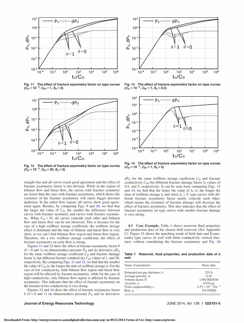
Figures 13 and 14 show the effect of fracture asymmetry factorh (h¼ 0 and 1) on dimensionless pressure PD and its derivative
dPD for the same wellbore storage coefficient CD and fractureconductivity CfD but different fracture damage factor Sk values of0.5, and 5, respectively. It can be seen from comparing Figs. 13and 14, we find that the larger the value of Sk is, the longer thetime of wellbore storage is and when Sk> 5, type curves with dif-ferent fracture asymmetry factor nearly coincide each other,which means the existence of fracture damage will decrease theeffect of fracture asymmetry. This also indicates that the effect offracture asymmetry on type curves with smaller fracture damageis very strong.
4.3 Case Example. Table 1 shows reservoir fluid propertiesand production data of the chosen field reservoir (See AppendixC). Figure 15 shows the matching result of field data and Econo-mides type curves of well with finite conductivity vertical frac-tures without considering the fracture asymmetry and Fig. 16
Fig. 11 The effect of fracture asymmetry factor on type curves(CD 5 1024, CfD 5 1, Sk 5 0)
Fig. 12 The effect of fracture asymmetry factor on type curves(CD 5 1024, CfD 5 50, Sk 5 0)
Fig. 13 The effect of fracture asymmetry factor on type curves(CD 5 1024, CfD 5 1, Sk 5 0.5)
Fig. 14 The effect of fracture asymmetry factor on type curves(CD 5 1024, CfD 5 1, Sk 5 5)
Table 1 Reservoir, fluid properties, and production data of awell
Name of parameters Basic data
Estimated net pay thickness, h 235 ftAverage porosity, / 0.18Volume factor, B 1.002 RB/STBviscosity, l 0.934 cpTotal compressibility ct 6.53� 10�4 Psi�1
Rate, q 334 STB/D
Journal of Energy Resources Technology JUNE 2014, Vol. 136 / 023101-5
Downloaded From: http://energyresources.asmedigitalcollection.asme.org/ on 09/21/2014 Terms of Use: http://asme.org/terms

shows the matching result of field data and new type curves con-sidering the fracture asymmetry presented in this paper. UsingEconomides type curves, we get the best matching of the datawhen CfD¼ 5 and CD¼ 10�4 and using new type curves, weobtain the best matching of the data when CfD¼ 5, CD¼ 10�4,and h¼ 0.8. Using the obtained matching points, we then calcu-late estimates of effective permeability, fracture half-length, andthe length of two wings. Table 2 shows the summary of results.
Matching results for new type curves: CfD¼ 5, CD¼ 10�4, andh¼ 0.8
½tD=CD�MP ¼ 1 ½pwD�MP ¼ 1
½Dt�MP ¼ 0:934hr ½Dp�MP ¼ 243:1psi
Sample calculationsPermeabilityFrom the pressure matching point relation for permeability, k,
given as
k ¼ 141:2qBl
h
½pwD�MP
½Dp�MP
We can obtain the permeability value, k, for this case
k ¼ 141:2ð334STB=DÞð1:002RB=STBÞð0:934cpÞ
235ft
1
234:1¼ 0:8md
Fracture half lengthSolving the time matching point relation for fracture half
length, xf, we obtain
xf ¼ 0:01624
ffiffiffiffiffiffiffiffiffiffiffiffiffiffiffiffiffiffiffiffiffiffiffiffiffiffiffiffiffiffiffiffiffiffiffiffiffik
/lct
1
CD
½Dt�MP
½tD=CD�MP
s
xf ¼ 0:01624
ffiffiffiffiffiffiffiffiffiffiffiffiffiffiffiffiffiffiffiffiffiffiffiffiffiffiffiffiffiffiffiffiffiffiffiffiffiffiffiffiffiffiffiffiffiffiffiffiffiffiffiffiffiffiffiffiffiffiffiffiffiffiffiffiffiffiffiffiffiffiffiffiffiffiffiffiffiffiffiffiffiffiffiffiffiffiffiffiffiffiffiffiffiffiffiffi0:8md
ð0:18Þð0:934cpÞð6:53� 10�6psi�1Þ1
10�4
0:934hr
1
s¼ 133:97ft
Finally, the length of two wings of the fracture can be calcu-lated using the following equations:
Lf1 ¼ xfð1� hÞ Lf2 ¼ xfð1þ hÞ
For this case, we obtain
Lf1 ¼ 133:97ft� ð1� 0:8Þ ¼ 26:8ft
Lf2 ¼ 133:97ft� ð1þ 0:8Þ ¼ 241:16ft
Table 2 shows comparison between new type curves and Econ-omides type curves, which indicates that the fracture asymmetrycan be evaluated through new type curves matching, while Econo-mides type curves can’t be used to make the estimation of fractureasymmetry. Contrast Figs. 15 with 16, It can be found that newtype curves reach perfect agreement with field data, which impliesfracture asymmetry is an important factor in type curvesmatching.
5 Conclusions
In this paper, a new constant rate solution for asymmetricallyfractured wells is presented. Based on the new solutions, severalimportant conclusions are obtained below.
(1) The semi-analytical solutions in this paper are presented inLaplace space, which doesn’t require time-discrete, there-fore reducing the account of computation and improvingthe computational efficiency.
(2) As both wellbore storage coefficient and fracture damagefactor are considered in the new model, it is convenient tomake well test interpretation.
(3) New type curves are established for different fracture asym-metry factors and different fracture conductivity. It isshown that a bigger fracture asymmetry factor will prolongthe time of wellbore storage effect and low fracture conduc-tivity will also prolong the time of wellbore storage effect.Therefore, to reduce wellbore storage effects, it is impor-tant to keep bigger fracture conductivity and fracture sym-metric during the hydraulic fracturing design.
(4) When the wellbore storage coefficient is small, the effect offracture asymmetry on early flow is very strong. The exis-tence of the fracture asymmetry will cause bigger pressure
Fig. 15 Match of pressure data for an example on Economidestype curves for a well of a finite conductivity vertical fracture(CD 5 1024, CfD 5 5)
Fig. 16 Match of pressure data for an example on new typecurves for a well of a finite conductivity asymmetric fracture(CD 5 1024, CfD 5 5 and h 5 0.8)
Table 2 Summary of calculative results
Name of parameters New type curves Economides type curves
The conductivity factor, CfD 5 5Storage coefficient, CD 10�4 10�4
Asymmetry factor, h 0.8 N/AFracture half-length, xf 133.97 ft 133.97 ftReservoir permeability, k 0.8 md 0.8 mdLeft wing value, Lf1 26.8 ft N/ARight wing value, Lf2 241.16 ft N/A
023101-6 / Vol. 136, JUNE 2014 Transactions of the ASME
Downloaded From: http://energyresources.asmedigitalcollection.asme.org/ on 09/21/2014 Terms of Use: http://asme.org/terms

depletion and make the starting time of linear flow occurearlier. The effect of fracture asymmetry on the fracture oflow conductivity is also very strong. The existence of frac-ture damage will decrease the effect of fracture asymmetry.This also indicates that the effect of fracture asymmetry ontype curves without fracture damage is very strong.
(5) The proposed type curves in this paper can be used to eval-uate the fracture asymmetry.
Acknowledgment
This paper was supported by Important National Science andTechnology Specific Projects of the twelfth five Years Plan Period(Grant No. 2011ZX05013-002) and the National Basic ResearchProgram of China (Grant No. 2011ZX05009-004).
Nomenclature
Dimensionless Variables: Real Domain
as ¼ asymmetric factor of the fracture in the literatureCfD ¼ dimensionless fracture conductivitypwD ¼ dimensionless well bottom pressurepfD ¼ dimensionless fracture pressuretD ¼ dimensionless time
xDj ¼ midpoint of the j segmenth ¼ fracture asymmetry factor
Dimensionless Variables: Laplace Domain
S ¼ time variable in Lapace domain, dimensionless~pD ¼ the pressure pD in Lapace domain
~pwD ¼ bottom pressure pwD in Lapace domain~pfD ¼ fracture pressure pfD in Lapace domain
~qðuÞ ¼ fracture rate q(x,t) in Lapace domain~qfD ¼ the fracture rate qfD in Lapace domain
Field Variables
ct ¼ total compressibility, 1/psik ¼ effective permeability, mDp ¼ formation pressure, psipi ¼ initial formation pressure, psi
Dpw ¼ pressure drop for oil, psiq ¼ rate of per unit fracture length from formation, m3/dl ¼ fluid viscosity, cph ¼ formation thickness, ft/ ¼ porosity, fractionr ¼ reservoir radius, ftt ¼ time variable, h
xf ¼ fracture half length, ftLf1 ¼ short wing length of the fracture, ftLf2 ¼ long wing length of the fracture, ft
w ¼ width of the damaged zone, ftx0 ¼ integral variable
kfwf ¼ the fracture conductivity, md ft
Special Functions
K0(x) ¼ modified Bessel function (second kind, zero order)K1(x) ¼ modified Bessel function (second kind, first order)I0(x) ¼ modified Bessel function (first kind, zero order)I1(x) ¼ modified Bessel function (first kind, first order)
Special Subscripts
f1 ¼ left wing of the fracturef2 ¼ right wing of the fractureD ¼ dimensionlesso ¼ oil
Appendix A
First, we must make Laplace transform to Eqs. (6)–(8), the fol-lowing equations can be obtained:
@2fpfD
@x2D
� pCfD
fqfD þ2p
sCfD
dðxD � hÞ ¼ 0 (A1)
Outer boundary conditions are given as in Laplace domain
@fpfD
@xD
� �xD¼�1
¼ 0 (A2)
@fpfD
@xD
� �xD¼1
¼ 0 (A3)
Now, we use Green Function Nðx0; xDÞ to integrate Eq. (A1), wecan knowð1
�1
Nðx0; xDÞ @fpfD
@x0� p
CfD
fqfDðx0; sÞ þ2p
sCfD
dðx0 � hÞ� �
¼ 0 (A4)
By integrating Eq. (4), it is easy to find the solution, that is
pfDð�1ÞN0ð�1; xDÞ � pfDN0ð1; xDÞ �p
CfD
ð1
�1
Nðx0; xDÞfqfDðx0; sÞdx0
þ 2pCfDs
Nðh; xDÞ þð1
�1
fpfDðx0; sÞN00dx0 (A5)
and hence require of N that
N00 ¼ dðx0 � xDÞ þ F
F ¼ � 1
2
N0ð�1; xDÞ ¼ 0
N0ð1; xDÞ ¼ 0
(A6)
Where F is the correct number, and it is easy to find the solutionof Eq. (A6)
Nðx0; xDÞ ¼ �x02
4þ
Ax0 þ Bð�1 � x0 < xDÞCx0 þ DðxD � x0 < 1Þ
�(A7)
According to Eq. (A7), we find that continuity of N at x’¼ xD,together with boundary conditions, the unknown coefficients canbe given as
A ¼ � 1
2
B ¼ � x2D
4þ xD
2� 1
6
C ¼ 1
2
D ¼ � x2D
4� xD
2� 1
6
8>>>>>>>>>><>>>>>>>>>>:(A8)
Substituting Eq. (A6) into Eq. (A5), the solution can be given as
fpfDðxD; sÞ ¼1
2
ð1
�1
fpfDðx0; sÞdx0 þ pCfD
ð1
�1
Nðx0; xDÞ~qfDðx0; sÞdx0
� 2pCfDs
Nðh; xDÞ (A9)
Journal of Energy Resources Technology JUNE 2014, Vol. 136 / 023101-7
Downloaded From: http://energyresources.asmedigitalcollection.asme.org/ on 09/21/2014 Terms of Use: http://asme.org/terms

we define
fpfDðsÞ½ �avg¼1
2
ð1
�1
fpfDðx0; sÞdx0 (A10)
Therefore, substituting Eqs. (A7) and (A8) into Eq. (A9), we canobtain the solution for the fracture model.
Appendix B
We consider formation flow model as a plane source in an infi-nite reservoir, so point source integral method must be used inLaplace domain. The mathematical model of point source for for-mation flow can be described in Laplace space
@2fpD
@r2D
þ 1
rD
@fpD
@rD
¼ sfpD (B1)
Inner boundary condition of point source can be decided by achanging flow rate, qfDðx; tDÞ, imposed to the wellbore. It can begiven as in Laplace domain
� rD
@fpD
@rD rD!0
¼ fqfDðsÞ (B2)
Outer boundary condition is
fpDð1; sÞ ¼ 0 (B3)
So, the general solution of Eqs. (B1)–(B3) could be expressed asin the form of Bessel Functions
fpD ¼ fqfDðsÞK0ðrD
ffiffispÞ (B4)
Using point sink integral method [8], a single fracture solutioncan be expressed as
fpDðxD; 0; sÞ ¼1
2
ð1
�1
fqfDðx0; sÞK0
nðxD � x0Þ2
1=2 ffiffisp o
dx0 (B5)
Appendix C
SI Metric Conversion Factors
bbl� 0.1589874 m3
cP� 0.001 Pa sft� 0.3048 mft2� 0.0929 m2
psi� 6.894757 kPa
References[1] Mcguire, W. J., and Sikora, V. J., 1960, “The Effect of Vertical Fractures on
Well Productivity,” SPE Paper No. 1618-G.[2] Prats, M., 1961, “Effect of Vertical Fracture on Reservoir Behavior-
Compressible Fluid Case,” 36th Annual Fall Meeting of SPE, Dallas, TX,Oct. 8–11, Paper No. SPE 98.
[3] Raghavan, R., Cady, G. V., and Ramey, H. J., 1972, “Well Test Analysis forVertically Fractured Wells,” J. Pet. Technol., 21, pp. 1014–1019.
[4] Ramey, H. J., Jr., and Gringarten, A. C., 1975, “Effect of High Volume VerticalFractures on Geothermal Steam Well Behavior,” Proceedings of Second United
Nations Symposium on the Use and Development of Geothermal Energy, SanFrancisco, CA, May 20–29.
[5] Gringarten, A. C., Ramey, H. J., Jr., and Raghavan, R., 1975, “Applied PressureAnalysis for Fractured Wells,” J. Pet. Technol., 27, pp. 887–892.
[6] Cinco-Ley, H., Samaniego-V., F., and Dominguez, N., 1978, “Transient Pres-sure Behavior for a Well With a Finite-Conductivity Vertical Fracture,” SPE J.,8(4), pp. 253–264.
[7] Cinco-Ley, H., and Fernando Samaniego-V., F., 1981, “Transient PressureAnalysis for Fractured Wells,” SPE J., 10(9), pp. 1749–1766.
[8] Ozkan, E., 1988, “Performance of Horizontal Wells,” Ph.D. Dissertation, Uni-versity of Tulsa, Tulsa, OK.
[9] Tiab, D., 1995, “Analysis of Pressure Derivative Without Type-Curve Match-ing-Skin and Wellbore Storage,” J. Pet. Sci. Eng, 12(3), pp. 171–181.
[10] Agarwal, R. G., Gardner, D. C., Kleinsteiber, S. W., and Fussell, D. D., 1998,“Analyzing Well Production Data Using Combined Type Curve and DeclineCurve Concepts,” SPE Form. Eval., 2(5), pp. 478–486.
[11] Pratikno, H., Rushing, J. A., and Blasingame, T. A., 2003, “Decline CurveAnalysis Using Type Curves-Fractured Wells,” SPE Annual Technical Confer-ence and Exhibition, Denver, CO, Oct. 5–8, Paper No. SPE 84287.
[12] Tiab, D., 2005, “Analysis of Derivative Data of Hydraulically FracturedWells by the Tiab’s Direct Synthesis Technique,” J. Pet. Sci. Eng., 49(1-2),pp. 1–21.
[13] Lei Z. D., Cheng S. Q., and Li X. F., 2007, “A New Method for Prediction ofProductivity of Fractured Horizontal Wells Based on Non-Steady Flow,”J. Hydrodyn., Ser. B, 19(4), pp. 494–500.
[14] Jacques, H. A., 2008, “Simplified Analytical Method for Estimating the Produc-tivity of a Horizontal Well Producing at Constant Rate or Constant Pressure,”J. Pet. Sci. Eng., 64(1), pp. 77–87.
[15] Lu, J., Ghedan, S., Zhu, T., and Tiab, D., 2011, “Non-Darcy Binomial Deliver-ability Equations for Partially Penetrating Vertical Gas Wells and HorizontalGas Wells,” ASME J. Energy Resour. Technol., 133, p. 043101.
[16] Tiab, D., Lu, J., Nguyen, H., and Owayed, J., 2010, “Evaluation of FractureAsymmetry of Finite-Conductivity Fractured Wells,” ASME J. Energy Resour.Technol., 132, p. 012901.
[17] Wang, L., Wang, X. D., Ding, X. M., Zhang, L., and Li, C., “Rate DeclineCurves Analysis of a Vertical Fractured Well With Fracture Face Damage,”ASME J. Energy Resour. Technol., 134, p. 032803.
[18] Bakhbergen, E. B., Aidarkhan, K., Andrew K. W., and Mikhail, P., “NumericalModeling of the Effects of Disproportionate Permeability Reduction Water-Shutoff Treatments on Water Coning,” ASME J. Energy Resour. Technol., 135,p. 011101.
[19] Ibrahim, M. M., Jia, H., Hisham A., and Nasr-El-Din, “Experimental Analysisof CO2 Injection on Permeability of Vuggy Carbonate Aquifers,” ASME J.Energy Resour. Technol., 135, p. 013301.
[20] Rahman, M. K., Salim, M. M., and Rahman, M. M. “Analytical Modeling ofNon-Darcy Flow-Induced Conductivity Damage in Propped HydraulicFractures,” ASME J. Energy Resour. Technol., 134(4), p. 043101.
[21] Jerzy, S., and Stanislaw, N. “Computer Modeling of Coal Bed Methane Recov-ery in Coal Mines,” ASME J. Energy Resour. Technol., 134(3), p. 032804.
[22] Crawford, P. B., and Landrum, B. L., 1955, “Effect of Unsymmetrical VerticalFractures on Procuction Capacity,” Trans. AIME, 204, pp. 251–254. Availableat: http://www.onepetro.org/mslib/app/Preview.do?paperNumber=SPE-000433-G&societyCode=SPE
[23] Narasimhan, T. N., and Palen, W. A., 1979, “A Purely Numerical Approach forAnalyzing Fluid Flow to a Well Inercepting a Vertical Fracture,” SPE Califor-nia Regional Meeting, Ventura, CA, Paper No. SPE 7983.
[24] Bennet, C. O., 1983, “Influence of Fracture Heterogeneity and Wing Length onthe Response of Vertically Fractured Wells,” SPE J., 23, pp. 219–230.
[25] Resurreic~ao, C. E. S., and Fernando, R., 1991, “Transient Rate Behavior ofFinite-Conductivity Asymmetrically Fractured Wells Producing at ConstantPressure,” Annual Technical Conference and Exhibition, Dallas, TX, Paper No.SPE 22657.
[26] Rodriguez, F., Cinco-Ley, H., and Samaniego, V. F., 1992, “Evaluation ofFracture Asymmetry of Finite-Conductivity Fractured Wells,” SPE Form.Eval., 8(2), pp. 233–239.
[27] Berumen, S., Tiab, D., and Rodriguez, F., 2000, “Constant Rate Solutions for aFractured Well With an Asymmetric Fracture,” J. Pet. Sci. Eng., 25, pp. 49–58.
[28] Nashawi, I. S., 2006, “Constant-Pressure Well Test Analysis of Finite-Conductivity Hydraulically Fractured Gas Wells Infuenced by Non-Darcy FlowEffects,” J. Pet. Sci. Eng., 53, pp. 225–238.
[29] Cinco-Ley, H., and Meng, H. Z., 1989, “Pressure Transient Analysis of WellsWith Finite Conductivity Vertical Fractures in Double Porosity Reservoirs,”Annual Technical Conference and Exhibition, Houston, TX, Paper No. SPE18172.
[30] Wang X. D., 2006, Mechanic Basis of Fluids Flow in Porous Media [M], Petro-leum Industry Publications, Beijing.
023101-8 / Vol. 136, JUNE 2014 Transactions of the ASME
Downloaded From: http://energyresources.asmedigitalcollection.asme.org/ on 09/21/2014 Terms of Use: http://asme.org/terms