Embed Size (px)
Citation preview
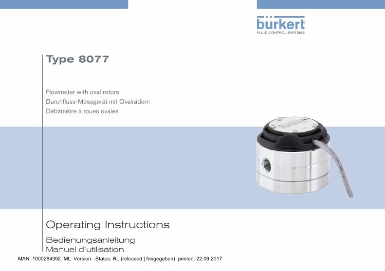
Operating InstructionsBedienungsanleitung Manuel d‘utilisation
Type 8077
Flowmeter with oval rotors
Durchfluss-Messgerät mit Ovalrädern
Débitmètre à roues ovales

We reserve the right to make technical changes without notice.Technische Änderungen vorbehalten.Sous réserve de modifications techniques.
© 2016 Bürkert SAS
Operating Instructions 1602/00 EU-ML_567834_ORIGINAL_FR
3
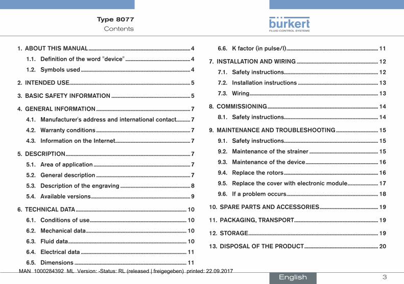
Contents
Type 8077
1. AboutthismAnuAl................................................................................ 4
1.1. Definitionoftheword"device"................................................... 4
1.2. symbolsused...................................................................................... 4
2. intenDeDuse............................................................................................... 5
3. bAsicsAfetyinformAtion.............................................................. 5
4. GenerAlinformAtion.......................................................................... 7
4.1. manufacturer'saddressandinternationalcontact........... 7
4.2. Warrantyconditions.......................................................................... 7
4.3. informationontheinternet........................................................... 7
5. Description.................................................................................................. 7
5.1. Areaofapplication............................................................................ 7
5.2. Generaldescription.......................................................................... 7
5.3. Descriptionoftheengraving....................................................... 8
5.4. Availableversions.............................................................................. 9
6. technicAlDAtA....................................................................................... 10
6.1. conditionsofuse............................................................................ 10
6.2. mechanicaldata............................................................................... 10
6.3. fluiddata............................................................................................. 10
6.4. electricaldata................................................................................... 11
6.5. Dimensions........................................................................................ 11
6.6. Kfactor(inpulse/l)........................................................................ 11
7. instAllAtionAnDWirinG................................................................ 12
7.1. safetyinstructions.......................................................................... 12
7.2. installationinstructions............................................................... 13
7.3. Wiring..................................................................................................... 13
8. commissioninG....................................................................................... 14
8.1. safetyinstructions.......................................................................... 14
9. mAintenAnceAnDtroubleshootinG................................. 15
9.1. safetyinstructions.......................................................................... 15
9.2. maintenanceofthestrainer...................................................... 15
9.3. maintenanceofthedevice......................................................... 16
9.4. replacetherotors.......................................................................... 16
9.5. replacethecoverwithelectronicmodule........................ 17
9.6. ifaproblemoccurs........................................................................ 18
10. spArepArtsAnDAccessories.............................................. 19
11. pAcKAGinG,trAnsport.................................................................. 19
12. storAGe...................................................................................................... 19
13. DisposAloftheproDuct.......................................................... 20
English
4
About this manual
Type 8077
1 AbouT This mAnuAlThis manual describes the entire life cycle of the device. Please keep this manual in a safe place, accessible to all users and any new owners.
thismanualcontainsimportantsafetyinformation.
Fully read this manual. In particular, observe the "Basic safety information" and "Intended use".
▶ Whatever the version of the device, this manual must be read and understood.
1.1 Definition of the word "device"
The word "device" used within this manual refers to the flowmeter type 8077.
1.2 symbols used
Danger
Warnsagainstanimminentdanger. ▶ Failure to observe this warning can result in death or in serious injury.
Warning
Warnsagainstapotentiallydangeroussituation. ▶ Failure to observe this warning can result in serious injury or even death.
attention
Warnsagainstapossiblerisk. ▶ Failure to observe this warning can result in substantial or minor injuries.
note
Warnsagainstmaterialdamage.
Important advice or recommendations.
refers to information contained in this manual or in other documents.
▶ Indicates a procedure to execute to avoid a danger.
→ Indicates a procedure to be carried out.
English
5
Intended use
Type 8077
2 inTenDeD use
useofthedevicethatdoesnotcomplywiththeinstructionscouldpresentriskstopeople,nearbyinstallationsandtheenvironment.
The flowmeter type 8077 is intended to measure the flow rate of fluids, especially of viscous fluids.
▶ Use this device in compliance with the characteristics and the conditions of commissioning and use specified in the contrac-tual documents and in this manual.
▶ Protect the device against electromagnetic interference, ultra-violet rays and, when installed outdoors, against the effects of climatic conditions
▶ Only operate a device in perfect working order. ▶ Properly transport, store, install and operate the device. ▶ Only use the device as intended.
3 bAsic sAfeTy informATionThis safety information does not take into account:
• any contingencies or occurrences that may arise during assembly, use and maintenance of the devices.
• the local safety regulations that the operator must ensure the staff in charge of installation and maintenance observe.
riskofinjuryduetohighpressureintheinstallation.
riskofinjuryduetoelectricalvoltage.
riskofinjuryduetohightemperaturesofthefluid.
riskofinjuryduetothenatureofthefluid.
Variousdangeroussituations
To avoid injury take care: ▶ not to use the device for the measurement of gas flow rates.
▶ not to use this device in explosive atmospheres. ▶ not to use this device in an environment incompatible with the materials it is made.
▶ not to make any internal or external modifications to the device.
English
6
Basic safety information
Type 8077
Variousdangeroussituations
To avoid injury take care:
▶ not to subject the device to any mechanical stresses.
▶ to prevent any unintentional power supply switch-on. ▶ to ensure that installation and maintenance work are carried out by qualified, authorised personnel in possession of the appropri-ate tools.
▶ to guarantee a set or controlled restarting of the process after a power supply interruption.
▶ to observe the general technical rules.
note
thedevicemaybedamagedbythefluidincontactwith. ▶ Systematically check the chemical compatibility of the compo-nent materials of the device and the fluids likely to come into contact with it (for example: alcohols, strong or concentrated acids, aldehydes, alkaline compounds, esters, aliphatic com-pounds, ketones, halogenated aromatics or hydrocarbons, oxidants and chlorinated agents).
note
elements/componentssensitivetoelectrostaticdischarges ▶ This device contains electronic components sensitive to electro-static discharges. They may be damaged if they are touched by an electrostatically charged person or object. In the worst case scenario, these components are instantly destroyed or go out of order as soon as they are activate
▶ To minimise or even avoid all damage due to an electrostatic discharge, take all the precautions described in the standard EN 61340-5-1
▶ Also ensure that you do not touch any of the live electrical components.
English
7
General information
Type 8077
4 GenerAl informATion
4.1 manufacturer's address and international contact
To contact the manufacturer of the device, use following address
Bürkert SAS
Rue du Giessen
BP 21
F-67220 TRIEMBACH-AU-VAL
You may also contact your local Bürkert sales office.
The addresses of our international sales offices are available on the internet at: www.burkert.com
4.2 Warranty conditions
The condition governing the legal warranty is the conforming use of the device in observance of the operating conditions specified in this manual.
4.3 information on the internet
You can find the user manuals and the technical data sheets regarding the type 8077 at: www.burkert.com
5 DescripTion
5.1 Area of application
The device is intended to measure, thanks to its oval rotors, the flow rate of viscous fluids. It must be combined with a remote instrument (refer to data sheet of the type 8077) which converts the pulse frequency due to oval rotors rotation.
5.2 General description
5.2.1 construction
The device is built of a fitting which includes oval rotors and of a cover including the electronic module with Hall effect sensor and Reed switch.
The oval rotors of the fitting contain magnets.
All the device versions provide an NPN transistor output and a Reed switch output.
The electrical connection is made by a 1 meter 5-wire cable.
English
8
Description
Type 8077
5.2.2 measuring principle
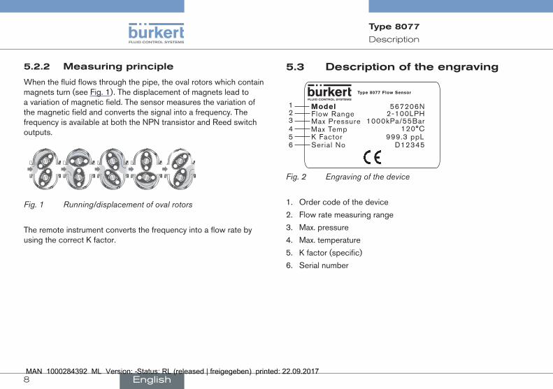
When the fluid flows through the pipe, the oval rotors which contain magnets turn (see Fig. 1). The displacement of magnets lead to a variation of magnetic field. The sensor measures the variation of the magnetic field and converts the signal into a frequency. The frequency is available at both the NPN transistor and Reed switch outputs.
Fig. 1 Running/displacement of oval rotors
The remote instrument converts the frequency into a flow rate by using the correct K factor.
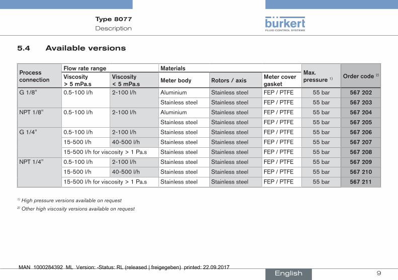
5.3 Description of the engraving
12345
ModelFlow RangeMax PressureMax TempK Factor
Type 8077 Flow Sensor
567206N2-100LPH
1000kPa/55Bar120°C
999.3 ppLSerial No D123456
Fig. 2 Engraving of the device
1. Order code of the device
2. Flow rate measuring range
3. Max. pressure
4. Max. temperature
5. K factor (specific)
6. Serial number
English
9
Description
Type 8077
5.4 Available versions
processconnection
flowraterange materialsmax.pressure1) ordercode2)Viscosity
>5mpa.sViscosity<5mpa.s
meterbody rotors/axismetercovergasket
G 1/8'' 0.5-100 l/h 2-100 l/h Aluminium Stainless steel FEP / PTFE 55 bar 567202
Stainless steel Stainless steel FEP / PTFE 55 bar 567203
NPT 1/8'' 0.5-100 l/h 2-100 l/h Aluminium Stainless steel FEP / PTFE 55 bar 567204
Stainless steel Stainless steel FEP / PTFE 55 bar 567205
G 1/4'' 0.5-100 l/h 2-100 l/h Stainless steel Stainless steel FEP / PTFE 55 bar 567206
15-500 l/h 40-500 l/h Stainless steel Stainless steel FEP / PTFE 55 bar 567207
15-500 l/h for viscosity > 1 Pa.s Stainless steel Stainless steel FEP / PTFE 55 bar 567208
NPT 1/4'' 0.5-100 l/h 2-100 l/h Stainless steel Stainless steel FEP / PTFE 55 bar 567209
15-500 l/h 40-500 l/h Stainless steel Stainless steel FEP / PTFE 55 bar 567210
15-500 l/h for viscosity > 1 Pa.s Stainless steel Stainless steel FEP / PTFE 55 bar 567211
1) High pressure versions available on request2) Other high viscosity versions available on request
English
10
Technical data
Type 8077
6 TechnicAl DATA
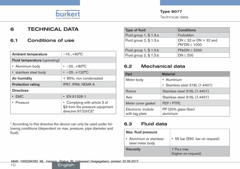
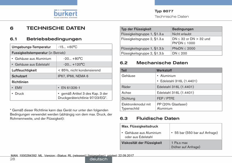
6.1 conditions of use
Ambienttemperature –15...+60°C
fluidtemperature(operating)
• Aluminium body • –20...+80°C
• stainless steel body • –20...+120°C
Airhumidity < 85%, non condensated
protectionrating IP67, IP66, NEMA 6
Directives
• EMC • EN 61326-1
• Pressure • Complying with article 3 of §3 from the pressure equipment directive 97/23/CE*
* According to this directive the device can only be used under fol-lowing conditions (dependent on max. pressure, pipe diameter and fluid):
typeoffluid conditionsFluid group 1, § 1.3.a ForbiddenFluid group 2, § 1.3.a DN ≤ 32 or DN > 32 and
PN*DN ≤ 1000
Fluid group 1, § 1.3.b PNxDN ≤ 2000Fluid group 2, § 1.3.b DN ≤ 200
6.2 mechanical data
part material
Meter body • Aluminium
• Stainless steel 316L (1.4401)
Rotors Stainless steel 316L (1.4401)
Axis Stainless steel 316L (1.4401)
Meter cover gasket FEP / PTFE
Electronic module with tag plate
PP (20% glass fiber) aluminium
6.3 fluid data
max.fluidpressure
• Aluminium or stainless steel meter body
• 55 bar (550 bar on request)
Viscosity 1 Pa.s max. (higher on request)
English
11
Technical data
Type 8077
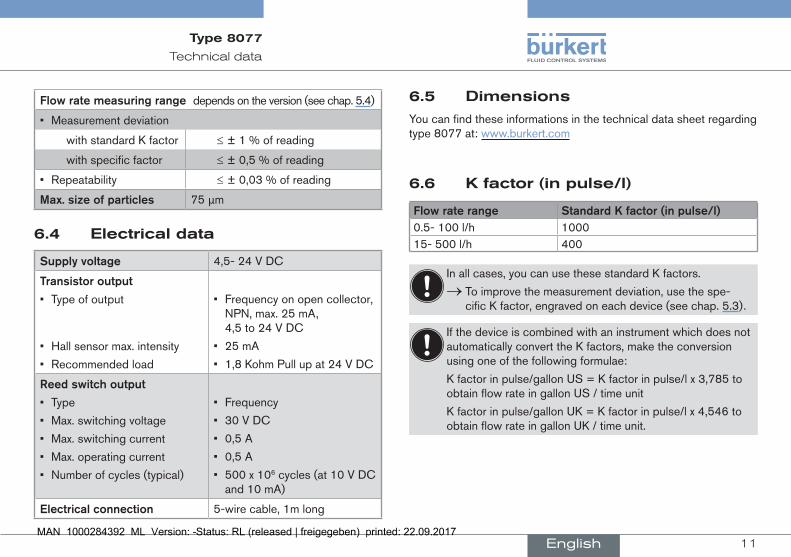
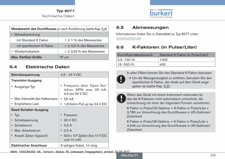
flowratemeasuringrangedepends on the version (see chap. 5.4)
• Measurement deviation
with standard K factor ≤ ± 1 % of reading
with specific factor ≤ ± 0,5 % of reading
• Repeatability ≤ ± 0,03 % of reading
max.sizeofparticles 75 µm
6.4 electrical data
supplyvoltage 4,5- 24 V DC
transistoroutput
• Type of output
• Hall sensor max. intensity
• Recommended load
• Frequency on open collector, NPN, max. 25 mA, 4,5 to 24 V DC
• 25 mA
• 1,8 Kohm Pull up at 24 V DC
reedswitchoutput
• Type
• Max. switching voltage
• Max. switching current
• Max. operating current
• Number of cycles (typical)
• Frequency
• 30 V DC
• 0,5 A
• 0,5 A
• 500 x 106 cycles (at 10 V DC and 10 mA)
electricalconnection 5-wire cable, 1m long
6.5 Dimensions
You can find these informations in the technical data sheet regarding type 8077 at: www.burkert.com
6.6 K factor (in pulse/l)
flowraterange standardKfactor(inpulse/l)0.5- 100 l/h 100015- 500 l/h 400
In all cases, you can use these standard K factors.
→ To improve the measurement deviation, use the spe-cific K factor, engraved on each device (see chap. 5.3).
If the device is combined with an instrument which does not automatically convert the K factors, make the conversion using one of the following formulae:
K factor in pulse/gallon US = K factor in pulse/l x 3,785 to obtain flow rate in gallon US / time unit
K factor in pulse/gallon UK = K factor in pulse/l x 4,546 to obtain flow rate in gallon UK / time unit.
English
12
Installation and wiring
Type 8077
7 insTAllATion AnD WirinG
7.1 safety instructions
Danger
riskofinjuryduetoelectricalvoltage. ▶ Disconnect the electrical power source for all the conductors and isolate it before carrying out work on the system.
▶ Observe all applicable accident protection and safety regula-tions for electrical equipment.
riskofinjuryduetohighpressureintheinstallation. ▶ Stop the circulation of fluid, cut off the pressure and drain the pipe before loosening the process connections.
riskofinjuryduetohighfluidtemperatures. ▶ Use safety gloves to handle the device. ▶ Stop the circulation of fluid and drain the pipe before loosening the process connections.
riskofinjuryduetothenatureofthefluid. ▶ Respect the regulations on accident prevention and safety relating to the use of aggressive fluid.
Warning
riskofinjuryduetonon-conforminginstallation. ▶ The electrical and fluid installation can only be carried out by qualified and authorized personnel with the appropriate tools.
▶ Install overload devices that are appropriate to the electrical installation.
riskofinjuryduetounintentionalswitchonofpowersupplyoruncontrolledrestartingoftheinstallation.
▶ Take appropriate measures to avoid unintentional activation of the installation.
▶ Guarantee a set or controlled restarting of the process subse-quent to the installation of the device.
English
13
Installation and wiring
Type 8077
7.3 Wiring
Danger
riskofinjuryduetoelectricalvoltage. ▶ Disconnect the electrical power for all the conductors and iso-late it before carrying out work on the device.
▶ Observe all applicable accident protection and safety regula-tions for electrical equipment.
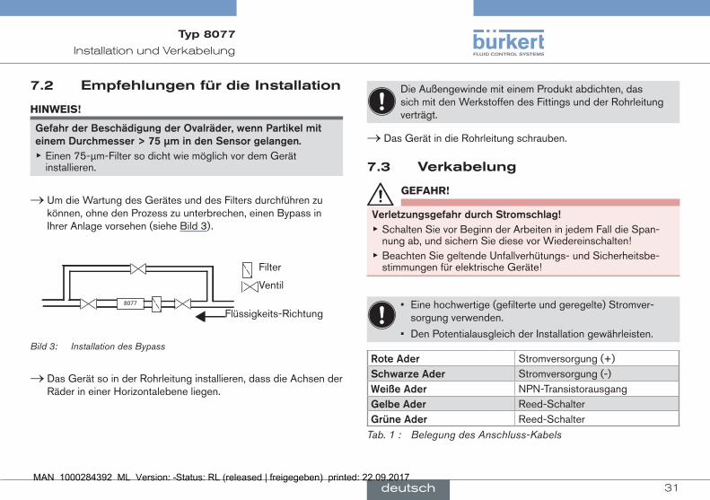
• Use a filtered and regulated electrical power supply.
• Make sure the installation is equipotential.
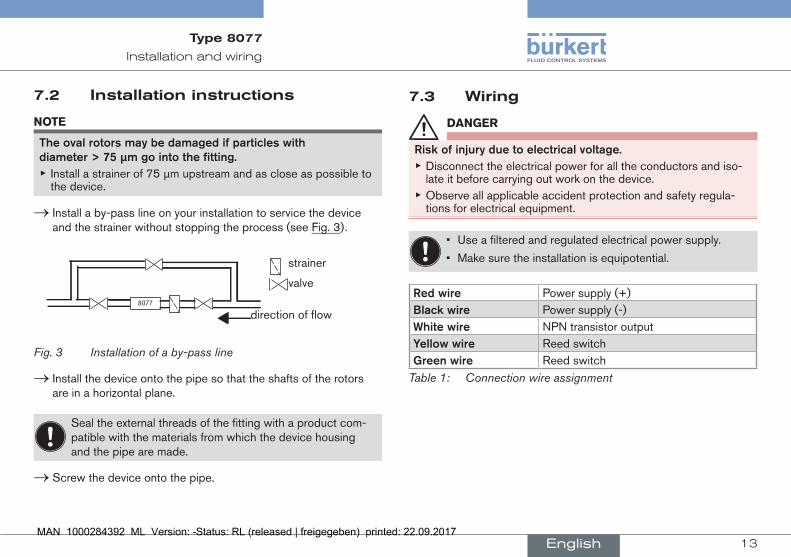
redwire Power supply (+)blackwire Power supply (-)Whitewire NPN transistor outputyellowwire Reed switchGreenwire Reed switch
Table 1: Connection wire assignment
7.2 installation instructions
note
theovalrotorsmaybedamagedifparticleswithdiameter>75µmgointothefitting.
▶ Install a strainer of 75 µm upstream and as close as possible to the device.
→ Install a by-pass line on your installation to service the device and the strainer without stopping the process (see Fig. 3).
valve
direction of flow
strainer
8077
Fig. 3 Installation of a by-pass line
→ Install the device onto the pipe so that the shafts of the rotors are in a horizontal plane.
Seal the external threads of the fitting with a product com-patible with the materials from which the device housing and the pipe are made.
→ Screw the device onto the pipe.
English
14
Commissioning
Type 8077
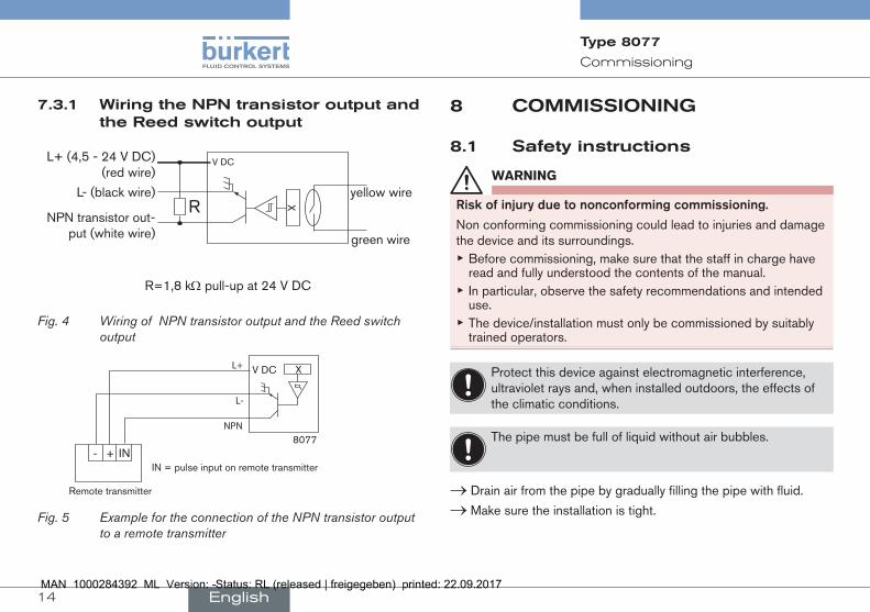
7.3.1 Wiring the npn transistor output and the reed switch output
X
V DCL+ (4,5 - 24 V DC) (red wire)
L- (black wire)
NPN transistor out-put (white wire)
Ryellow wire
green wire
R=1,8 kW pull-up at 24 V DC
Fig. 4 Wiring of NPN transistor output and the Reed switch output
8077
XV DC
NPN
L-
L+
+- IN
Remote transmitter
IN = pulse input on remote transmitter
Fig. 5 Example for the connection of the NPN transistor output to a remote transmitter
8 commissioninG
8.1 safety instructions
Warning
riskofinjuryduetononconformingcommissioning.
Non conforming commissioning could lead to injuries and damage the device and its surroundings.
▶ Before commissioning, make sure that the staff in charge have read and fully understood the contents of the manual.
▶ In particular, observe the safety recommendations and intended use.
▶ The device/installation must only be commissioned by suitably trained operators.
Protect this device against electromagnetic interference, ultraviolet rays and, when installed outdoors, the effects of the climatic conditions.
The pipe must be full of liquid without air bubbles.
→ Drain air from the pipe by gradually filling the pipe with fluid.
→ Make sure the installation is tight.
English
15
Maintenance and troubleshooting
Type 8077
9 mAinTenAnce AnD TroubleshooTinG
9.1 safety instructions
Danger
riskofinjuryduetohighpressureintheinstallation. ▶ Stop the circulation of fluid, cut off the pressure and drain the pipe before loosening the process connections.
riskofinjuryduetoelectricalvoltage. ▶ Shut down and isolate the electrical power source before carry-ing out work on the system.
▶ Observe all applicable accident protection and safety regula-tions for electrical equipment.
riskofinjuryduetothenatureofthefluid. ▶ Respect the prevailing regulations on accident prevention and safety relating to the use of aggressive fluids.
riskofinjuryduetohighfluidtemperatures. ▶ Use safety gloves to handle the device. ▶ Stop the circulation of fluid and drain the pipe before loosening the process connections.
▶ Keep all easily flammable material and fluid away from the device.
Warning
riskofinjuryduetonon-conformingmaintenance. ▶ Maintenance must only be carried out by qualified and skilled staff with the appropriate tools.
▶ Guarantee a set or controlled restarting of the process, after a power supply interruption.
9.2 maintenance of the strainer
→ After the circulation of 200 litres of fluid, examine the strainer for particles. If necessary clean the strainer with a product com-patible with the materials from which it is made.
→ Regularly examine the strainer for good condition, in particular when the flow rate decreases. If necessary clean the strainer with a product compatible with the materials from which it is made.
English
16
Maintenance and troubleshooting
Type 8077
9.3 maintenance of the device
→ Regularly examine the gasket and the oval rotors for good con-dition. Follow the instructions on chap. 9.4.
Clean the device with a cloth slightly dampened with water or a cleaning liquid compatible with the materials the device is made of.
Your Bürkert supplier is at your disposal for any further information.
16
5
7
43
2
9
8
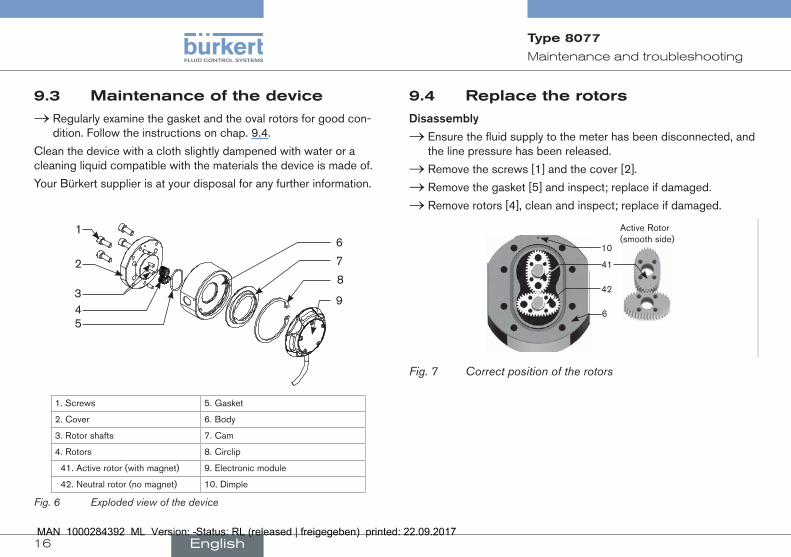
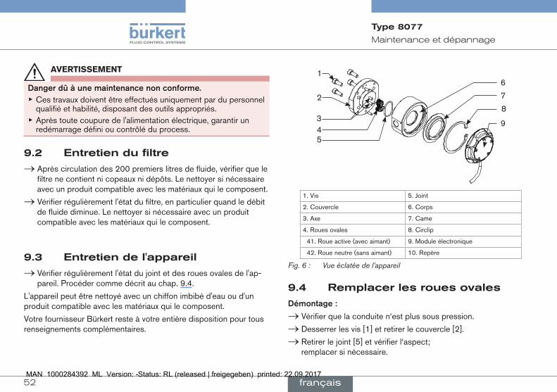
1. Screws 5. Gasket
2. Cover 6. Body
3. Rotor shafts 7. Cam
4. Rotors 8. Circlip
41. Active rotor (with magnet) 9. Electronic module
42. Neutral rotor (no magnet) 10. Dimple
Fig. 6 Exploded view of the device
9.4 replace the rotors
Disassembly
→ Ensure the fluid supply to the meter has been disconnected, and the line pressure has been released.
→ Remove the screws [1] and the cover [2].
→ Remove the gasket [5] and inspect; replace if damaged.
→ Remove rotors [4], clean and inspect; replace if damaged.
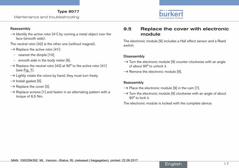
41
10
42
Active Rotor(smooth side)
6
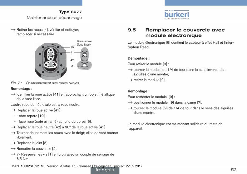
Fig. 7 Correct position of the rotors
English
17
Maintenance and troubleshooting
Type 8077
9.5 replace the cover with electronic module
The electronic module [9] includes a Hall effect sensor and a Reed switch.
Disassembly
→ Turn the electronic module [9] counter-clockwise with an angle of about 90° to unlock it.
→ Remove the electronic module [9].
reassembly
→ Place the electronic module [9] in the cam [7].
→ Turn the electronic module [9] clockwise with an angle of about 90° to lock it.
The electronic module is locked with the complete device.
reassembly
→ Identify the active rotor [41] by running a metal object over the face (smooth side).
The neutral rotor [42] is the other one (without magnet).
→ Replace the active rotor [41]:
- nearest the dimple [10],
- smooth side in the body meter [6].
→ Replace the neutral rotor [42] at 90° to the active rotor [41] (see Fig. 7).
→ Lightly rotate the rotors by hand; they must turn freely.
→ Install gasket [5].
→ Replace the cover [2].
→ Replace screws [1] and fasten in an alternating pattern with a torque of 6,5 Nm.
English
18
Maintenance and troubleshooting
Type 8077
9.6 if a problem occurs
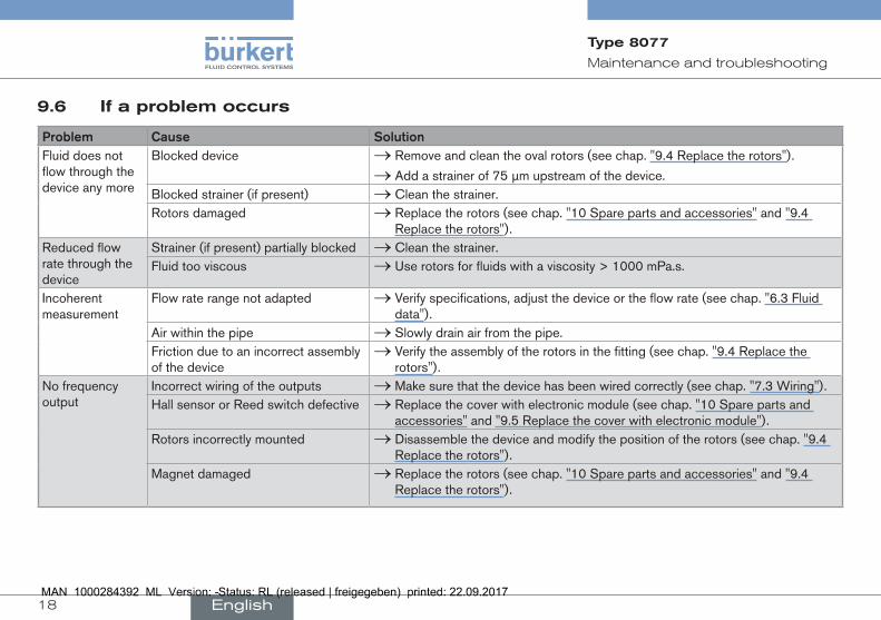
problem cause solutionFluid does not flow through the device any more
Blocked device → Remove and clean the oval rotors (see chap. "9.4 Replace the rotors").
→ Add a strainer of 75 µm upstream of the device.Blocked strainer (if present) → Clean the strainer.Rotors damaged → Replace the rotors (see chap. "10 Spare parts and accessories" and "9.4
Replace the rotors").Reduced flow rate through the device
Strainer (if present) partially blocked → Clean the strainer.Fluid too viscous → Use rotors for fluids with a viscosity > 1000 mPa.s.
Incoherent measurement
Flow rate range not adapted → Verify specifications, adjust the device or the flow rate (see chap. "6.3 Fluid data").
Air within the pipe → Slowly drain air from the pipe.Friction due to an incorrect assembly of the device
→ Verify the assembly of the rotors in the fitting (see chap. "9.4 Replace the rotors").
No frequency output
Incorrect wiring of the outputs → Make sure that the device has been wired correctly (see chap. "7.3 Wiring").Hall sensor or Reed switch defective → Replace the cover with electronic module (see chap. "10 Spare parts and
accessories" and "9.5 Replace the cover with electronic module").Rotors incorrectly mounted → Disassemble the device and modify the position of the rotors (see chap. "9.4
Replace the rotors").Magnet damaged → Replace the rotors (see chap. "10 Spare parts and accessories" and "9.4
Replace the rotors").
English
19
Spare parts and accessories
Type 8077
10 spAre pArTs AnD Accessories
Caution
riskofinjuryanddamagecausedbytheuseofunsuitableparts.
Incorrect accessories and unsuitable spare parts may cause injuries and damage the device and the surrounding area.
▶ Use only original accessories and original spare parts from Bürkert.
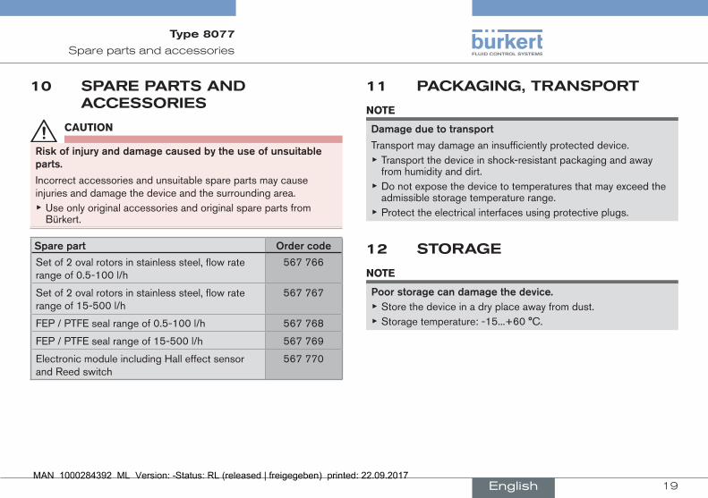
sparepart ordercode
Set of 2 oval rotors in stainless steel, flow rate range of 0.5-100 l/h
567 766
Set of 2 oval rotors in stainless steel, flow rate range of 15-500 l/h
567 767
FEP / PTFE seal range of 0.5-100 l/h 567 768
FEP / PTFE seal range of 15-500 l/h 567 769
Electronic module including Hall effect sensor and Reed switch
567 770
11 pAcKAGinG, TrAnsporT
note
Damageduetotransport
Transport may damage an insufficiently protected device. ▶ Transport the device in shock-resistant packaging and away from humidity and dirt.
▶ Do not expose the device to temperatures that may exceed the admissible storage temperature range.
▶ Protect the electrical interfaces using protective plugs.
12 sTorAGe
note
poorstoragecandamagethedevice. ▶ Store the device in a dry place away from dust. ▶ Storage temperature: -15...+60 °C.
English
20
Disposal of the product
Type 8077
13 DisposAl of The proDucT → Dispose of the device and its packaging in an environmental-ly-friendly way.
note
Damagetotheenvironmentcausedbypartscontaminatedbythefluid.
▶ Comply with the national and/or local regulations which concern the area of waste disposal.
English
21
Inhaltverzeichnis
Typ 8077
14. DiebeDienunGsAnleitunG......................................................... 22
14.1.begriffsdefinition"Gerät"............................................................ 22
14.2.Darstellungsmittel.......................................................................... 22
15. bestimmunGsGemässerGebrAuch................................... 23
16. GrunDleGenDesicherheitshinWeise............................. 23
17. AllGemeinehinWeise...................................................................... 25
17.1.herstelleradresseundinternationaleKontaktad-ressen.................................................................................................... 25
17.2.Gewährleistung................................................................................ 25
17.3.informationeniminternet........................................................... 25
18. beschreibunG...................................................................................... 25
18.1.Vorgesehenereinsatzbereich.................................................. 25
18.2.Allgemeinebeschreibung.......................................................... 25
18.3.beschreibungderKennzeichnung............................................ 26
18.4.VerfügbareVersionen................................................................... 27
19. technischeDAten............................................................................. 28
19.1.betriebsbedingungen................................................................... 28
19.2.mechanischeDaten....................................................................... 28
19.3.fluidischeDaten.............................................................................. 28
19.4.elektrischeDaten............................................................................ 29
19.5.Abmessungen................................................................................... 29
19.6.K-faktoren(inpulse/liter)........................................................ 29
20. instAllAtionunDVerKAbelunG............................................ 30
20.1.sicherheitshinweise...................................................................... 30
20.2.empfehlungenfürdieinstallation.......................................... 31
20.3.Verkabelung....................................................................................... 31
21. inbetriebnAhme.................................................................................. 32
21.1.sicherheitshinweise...................................................................... 32
22. WArtunG,problemlösunG........................................................ 33
22.1.sicherheitshinweise...................................................................... 33
22.2.Wartungdesfilters........................................................................ 33
22.3.WartungdesGerätes.................................................................... 34
22.4.ovalräderersetzen......................................................................... 35
22.5.elektronikmodulersetzen.......................................................... 35
22.6.problemelösen................................................................................ 36
23. ersAtzteile,zubehör.................................................................... 37
24. VerpAcKunG,trAnsport............................................................. 37
25. lAGerunG.................................................................................................. 37
26. entsorGunGDesGeräts............................................................ 38
deutsch
22
Die Bedienungsanleitung
Typ 8077
1 Die beDienunGsAnleiTunGDie Bedienungsanleitung beschreibt den gesamten Lebenszyklus des Geräts. Bewahren Sie diese Anleitung für jeden Benutzer gut zugänglich auf. Die Anleitung muss jedem neuen Eigentümer des Geräts wieder zur Verfügung stehen.
Wichtigeinformationenzursicherheit!
Lesen Sie die Bedienungsanleitung sorgfältig durch. Beachten Sie vor allem die Kapitel "Grundlegende Sicherheitshinweise"und"Bestimmungsgemäßer Gebrauch".
▶ Die Bedienungsanleitung muss gelesen und verstanden werden.
1.1 begriffsdefinition "Gerät"
Der in dieser Anleitung verwendete Begriff "Gerät" steht immer für das Durchfluss-Messgerät Typ 8077.
1.2 Darstellungsmittel
gefahr!
WarntvoreinerunmittelbarenGefahr! ▶ Bei Nichtbeachtung sind Tod oder schwere Verletzungen die Folge.
Warnung!
Warntvoreinermöglichen,gefährlichensituation! ▶ Bei Nichtbeachtung drohen schwere Verletzungen oder Tod.
VorsiCht!
WarntvoreinermöglichenGefährdung! ▶ Bei Nichtbeachtung drohen mittelschwere oder leichte Verletzungen.
hinWeis!
Warntvorsachschäden!
Wichtige Tipps und Empfehlungen.
Verweist auf Informationen in dieser Bedienungsanleitung oder in anderen Dokumentationen.
▶ Markiert eine Anweisung zur Vermeidung einer Gefahr.
→ Markiert einen auszuführenden Arbeitsschritt.
deutsch
23
Bestimmungsgemäßer Gebrauch
Typ 8077
2 besTimmunGsGemässer GebrAuch
beinichtbestimmungsgemäßemeinsatzdesGeräteskönnenGefahrenfürpersonen,Anlageninderumgebungunddieumweltentstehen.
Das Durchfluss-Messgerät Typ 8077 ist zur Durchflussmessung von Flüssigkeiten, insbesondere viskosen Flüssigkeiten bestimmt.
▶ Für den Einsatz die in den Vertragsdokumenten und der Bedie-nungsanleitung spezifizierten zulässigen Daten, Betriebs- und Einsatzbedingungen beachten.
▶ Schützen Sie das Gerät vor elektromagnetischen Stö-rungen, U.V.-Bestrahlung und bei Außenanwendung vor Witterungseinflüssen.
▶ Das Gerät nur in einwandfreiem Zustand betreiben. ▶ Auf sachgerechte Lagerung, Transport, Installation und Bedie-nung achten.
▶ Das Gerät nur bestimmungsgemäß einsetzen.
3 GrunDleGenDe sicherheiTshinWeise
Diese Sicherheitshinweise berücksichtigen keine bei Montage, Betrieb und Wartung auftretenden, Zufälle und Ereignisse.
Der Betreiber ist dafür verantwortlich, dass die ortsbezogenen Sicherheitsbestimmungen, auch in Bezug auf das Personal, einge-halten werden.
Verletzungsgefahrdurchelektrischespannung!
VerletzungsgefahrdurchhohenDruckinderAnlage!
Verletzungsgefahrdurchhoheflüssigkeitstemperaturen!
VerletzungsgefahrdurchdieArtderflüssigkeit!
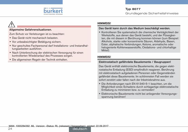
AllgemeineGefahrensituationen.
Zum Schutz vor Verletzungen ist zu beachten: ▶ Das Gerät nicht für die Durchflussmessung von Gas einsetzen. ▶ Das Gerät nicht im explosionsgefährdeten Bereich verwenden. ▶ Auf die Verträglichkeit der Gerätewerkstoffe mit berührenden Substanzen achten.
▶ Am Gerät keine inneren oder äußeren Veränderungen vornehmen.
deutsch
24
Grundlegende Sicherheitshinweise
Typ 8077
AllgemeineGefahrensituationen.
Zum Schutz vor Verletzungen ist zu beachten: ▶ Das Gerät nicht mechanisch belasten. ▶ Vor unbeabsichtigter Betätigung sichern. ▶ Nur geschultes Fachpersonal darf Installations- und Instandhal-tungsarbeiten ausführen.
▶ Nach Unterbrechung der elektrischen Versorgung für einen kontrollierten Wiederanlauf des Prozesses sorgen.
▶ Die allgemeinen Regeln der Technik einhalten.
hinWeis!
DasGerätkanndurchdasmediumbeschädigtwerden. ▶ Kontrollieren Sie systematisch die chemische Verträglichkeit der Werkstoffe, aus denen das Gerät besteht, und der Flüssigkei-ten, die mit diesem in Berührung kommen können (zum Beispiel: Alkohole, starke oder konzentrierte Säuren, Aldehyde, Basen, Ester, aliphatische Verbindungen, Ketone, aromatische oder halogenierte Kohlenwasserstoffe, Oxidations- und chlorhaltige Mittel).
hinWeis!
elektrostatischgefährdetebauelemente/baugruppen!
Das Gerät enthält elektronische Bauelemente, die gegen elekt-rostatische Entladung (ESD) empfindlich reagieren. Berührung mit elektrostatisch aufgeladenen Personen oder Gegenständen gefährdet diese Bauelemente. Im schlimmsten Fall werden sie sofort zerstört oder fallen nach der Inbetriebnahme aus.
▶ Die Anforderungen nach EN 61340-5-1 beachten, um die Möglichkeit eines Schadens durch schlagartige elektrostatische Entladung zu minimieren bzw. zu vermeiden!
▶ Elektronische Bauelemente nicht bei anliegender Versorgungs-spannung berühren!
deutsch
25
Allgemeine Hinweise
Typ 8077
4 AllGemeine hinWeise
4.1 herstelleradresse und internationale Kontaktadressen
Sie können mit dem Hersteller des Gerätes unter folgender Adresse
Kontakt aufnehmen:
Bürkert SAS
Rue du Giessen
BP 21
F-67220 TRIEMBACH-AU-VAL
oder wenden Sie sich an Ihren lokal zuständigen Vertriebsmitarbeiter von Bürkert.
Die internationalen Kontaktadressen finden Sie im Internet unter: www.burkert.com
4.2 Gewährleistung
Voraussetzung für die Gewährleistung ist der bestimmungsgemäße Gebrauch des Gerätes unter Beachtung der im vorliegenden Handbuch spezifizierten Einsatzbedingungen.
4.3 informationen im internet
Bedienungsanleitungen und Datenblätter zum Typ 8077 finden Sie im Internet unter: www.buerkert.de
5 beschreibunG
5.1 Vorgesehener einsatzbereich
Das Gerät ermöglicht aufgrund seiner Ovalräder die Durchfluss-messung viskoser Flüssigkeiten. Es muss in Verbindung mit einem abgesetzten Gerät (siehe Datenblatt Typ 8077) zur Erfassung/Kon-vertierung der durch die Rotation der Ovalräder erzeugten Impulsfre-quenz verwendet werden.
5.2 Allgemeine beschreibung
5.2.1 Aufbau
Das Gerät besteht aus einem Fitting mit integrierten Ovalrädern und einem Elektronikmodul, das ein Halleffekt-Sensor und ein Reed-Schalter enthält.
Die Ovalräder des Fittings enthalten Magnete.
Alle Ausführungen des Sensors weisen einen NPN Transistor-ausgang und einen Reed-Schalter auf.
Der elektrische Anschluss erfolgt über ein 1m-langes 5-adriges Kabel.
deutsch
26
Beschreibung
Typ 8077
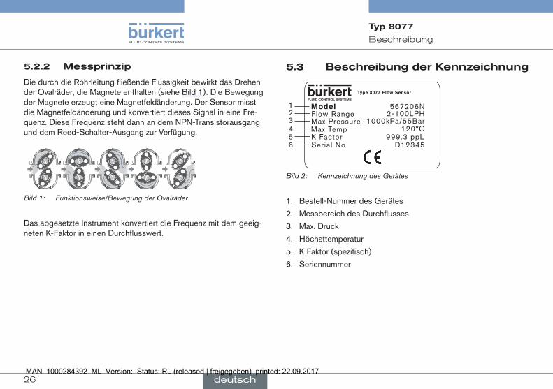
5.2.2 messprinzip
Die durch die Rohrleitung fließende Flüssigkeit bewirkt das Drehen der Ovalräder, die Magnete enthalten (siehe Bild 1). Die Bewegung der Magnete erzeugt eine Magnetfeldänderung. Der Sensor misst die Magnetfeldänderung und konvertiert dieses Signal in eine Fre-quenz. Diese Frequenz steht dann an dem NPN-Transistorausgang und dem Reed-Schalter-Ausgang zur Verfügung.
Bild 1: Funktionsweise/Bewegung der Ovalräder
Das abgesetzte Instrument konvertiert die Frequenz mit dem geeig-neten K-Faktor in einen Durchflusswert.
5.3 beschreibung der Kennzeichnung
12345
ModelFlow RangeMax PressureMax TempK Factor
Type 8077 Flow Sensor
567206N2-100LPH
1000kPa/55Bar120°C
999.3 ppLSerial No D123456
Bild 2: Kennzeichnung des Gerätes
1. Bestell-Nummer des Gerätes
2. Messbereich des Durchflusses
3. Max. Druck
4. Höchsttemperatur
5. K Faktor (spezifisch)
6. Seriennummer
deutsch
27
Beschreibung
Typ 8077
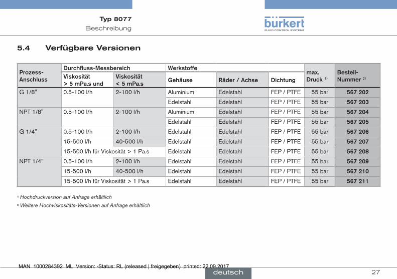
5.4 Verfügbare Versionen
prozess-Anschluss
Durchfluss-messbereich Werkstoffemax.Druck1)
bestell-nummer2)Viskosität
>5mpa.sundViskosität<5mpa.s
Gehäuse räder/Achse Dichtung
G 1/8'' 0.5-100 l/h 2-100 l/h Aluminium Edelstahl FEP / PTFE 55 bar 567202
Edelstahl Edelstahl FEP / PTFE 55 bar 567203
NPT 1/8'' 0.5-100 l/h 2-100 l/h Aluminium Edelstahl FEP / PTFE 55 bar 567204
Edelstahl Edelstahl FEP / PTFE 55 bar 567205
G 1/4'' 0.5-100 l/h 2-100 l/h Edelstahl Edelstahl FEP / PTFE 55 bar 567206
15-500 l/h 40-500 l/h Edelstahl Edelstahl FEP / PTFE 55 bar 567207
15-500 l/h für Viskosität > 1 Pa.s Edelstahl Edelstahl FEP / PTFE 55 bar 567208
NPT 1/4'' 0.5-100 l/h 2-100 l/h Edelstahl Edelstahl FEP / PTFE 55 bar 567209
15-500 l/h 40-500 l/h Edelstahl Edelstahl FEP / PTFE 55 bar 567210
15-500 l/h für Viskosität > 1 Pa.s Edelstahl Edelstahl FEP / PTFE 55 bar 567211
1)Hochdruckversion auf Anfrage erhältlich2)Weitere Hochviskositäts-Versionen auf Anfrage erhältlich
deutsch
28
Technische Daten
Typ 8077
6 Technische DATen
6.1 betriebsbedingungen
umgebungs-temperatur -15... +60°C
fussigkeitstemperatur(in Betrieb)
• Gehäuse aus Aluminium -20... +80°C
• Gehäuse aus Edelstahl -20... +120°C
luftfeuchtigkeit < 85%, nicht kondensierend
schutzart IP67, IP66, NEMA 6
richtlinien
• EMV • EN 61326-1
• Druck • gemäß Artikel 3 des Kap. 3 der Druckgeräterichtlinie 97/23/EG*.
* Gemäß dieser Richtlinie kann das Gerät nur unter den folgenden Bedingungen verwendet werden (abhängig von dem max. Druck, der Rohrnennweite, und der Flüssigkeit):
typderflüssigkeit bedingungenFlüssigkeitsgruppe 1, §1.3.a Nicht erlaubtFlüssigkeitsgruppe 2, §1.3.a DN ≤ 32 or DN > 32 und
PN*DN ≤ 1000
Flüssigkeitsgruppe 1, §1.3.b PNxDN ≤ 2000Flüssigkeitsgruppe 2, §1.3.b DN ≤ 200
6.2 mechanische Daten
teil Werkstoff
Gehäuse • Aluminium
• Edelstahl 316L (1.4401)
Räder Edelstahl 316L (1.4401)
Achse Edelstahl 316L (1.4401)
Dichtung FEP / PTFE
Elektronikmodul mit Typenschild
PP (20% Glasfaser) Aluminium
6.3 fluidische Daten
max.flüssigkeitsdruck
• Gehäuse aus Aluminium oder aus Edelstahl
• 55 bar (550 bar auf Anfrage)
Viskositätderflüssigkeit 1 Pa.s max (höher auf Anfrage)
deutsch
29
Technische Daten
Typ 8077
messbereichdesDurchflussesje nach Ausführung (siehe Kap. 5.4)
• Messabweichung
mit Standard K Faktor ≤ ± 1 % des Messwertes
mit spezifischem K Faktor ≤ ± 0,5 % des Messwertes
• Wiederholbarkeit ≤ ± 0,03 % des Messwertes
max.partikel-Größe 75 µm
6.4 elektrische Daten
betriebsspannung 4,5 - 24 V DC
transistor-Ausgang
• Ausgangs-Typ
• Max. Intensität des Hallsensors
• Empfohlene Last
• Frequenz über Open Kol-lektor, NPN, max. 25 mA, 4,5 bis 24 V DC
• 25 mA
• 1,8 Kohm Pull up bei 24 V DC
reed-schalter-Ausgang
• Typ
• Schaltspannung
• Schaltstrom
• Max. Arbeitsstrom
• Anzahl Zyklen (typisch)
• Frequenz
• 30 V DC
• 0,5 A
• 0,5 A
• 500 x 106 Zyklen (bei 10 V DC und 10 mA)
elektrischerAnschluss 5-adriges Kabel, 1m lang
6.5 Abmessungen
Informationen finden Sie in Datenblatt zu Typ 8077 unter: www.buerkert.de
6.6 K-faktoren (in pulse/liter)
Durchfluss-Messbereich Standard K-Faktor (in Pulse/Liter)0.5- 100 l/h 100015- 500 l/h 400
In allen Fällen können Sie den Standard K-Faktor benutzen.
→ Um die Messgenauigkeit zu erhöhen, benutzen Sie den spezifischen K-Faktor, der direkt auf dem Gerät ange-geben ist (siehe Kap. 5.3).
Wenn das Gerät mit einem Instrument verbunden ist, das die K-Faktoren nicht automatisch umrechnet, die Umrechnung mit einer der folgenden Formeln vornehmen:
K-Faktor in Pulse/US-Gallone = K-Faktor in Pulse/Liter x 3,785 zur Umrechnung des Durchflusses in US-Gallonen/Zeiteinheit
K-Faktor in Pulse/UK-Gallone = K-Faktor in Pulse/Liter x 4,546 zur Umrechnung des Durchflusses in UK-Gallonen/Zeiteinheit
deutsch
30
Installation und Verkabelung
Typ 8077
7 insTAllATion unD VerKAbelunG
7.1 sicherheitshinweise
gefahr!
VerletzungsgefahrdurchhohenDruckinderAnlage! ▶ Vor dem Lösen der Prozessanschlüsse die Anlage druckfrei schalten und die Flüssigkeitszirkulation stoppen.
Verletzungsgefahrdurchstromschlag! ▶ Schalten Sie vor Beginn der Arbeiten in jedem Fall die Span-nung ab, und sichern Sie diese vor Wiedereinschalten!
▶ Beachten Sie geltende Unfallverhütungs- und Sicherheitsbe-stimmungen für elektrische Geräte!
VerletzungsgefahraufgrundderArtderflüssigkeit! ▶ Beachten Sie die Regeln, die auf dem Gebiet der Unfallverhütung und der Sicherheit in Kraft sind und die sich auf die Verwendung gefährlicher Produkte beziehen.
Verletzungsgefahrdurchhoheflüssigkeitstemperaturen! ▶ Das Gerät nur mit Schutzhandschuhen anfassen. ▶ Vor dem Lösen der Prozessanschlüsse die Flüssigkeitszirkula-tion stoppen und die Rohrleitung leeren.
▶ Leicht brennbare Materialien und Medien vom Gerät fernhalten.
Warnung!
Verletzungsgefahrbeiunsachgemäßerinstallation! ▶ Fluidische und elektrische Installationen dürfen nur durch auto-risiertes Fachpersonal und mit geeignetem Werkzeug durchge-führt werden!
▶ Verwenden Sie unbedingt geeignete Sicherheitsvorrichtun-gen (ordnungsgemäß dimensionierte Sicherungen und/oder Sicherungsautomat).
▶ Verletzungsgefahr durch ungewolltes Einschalten der Anlage und unkontrollierten Wiederanlauf!
▶ Anlage vor unbeabsichtigtem Betätigen sichern. ▶ Nach der Installation einen kontrollierten Wiederanlauf gewährleisten.
deutsch
31
Installation und Verkabelung
Typ 8077
Die Außengewinde mit einem Produkt abdichten, das sich mit den Werkstoffen des Fittings und der Rohrleitung verträgt.
→ Das Gerät in die Rohrleitung schrauben.
7.3 Verkabelung
gefahr!
Verletzungsgefahrdurchstromschlag! ▶ Schalten Sie vor Beginn der Arbeiten in jedem Fall die Span-nung ab, und sichern Sie diese vor Wiedereinschalten!
▶ Beachten Sie geltende Unfallverhütungs- und Sicherheitsbe-stimmungen für elektrische Geräte!
• Eine hochwertige (gefilterte und geregelte) Stromver-sorgung verwenden.
• Den Potentialausgleich der Installation gewährleisten.
roteAder Stromversorgung (+)schwarzeAder Stromversorgung (-)WeißeAder NPN-TransistorausgangGelbeAder Reed-SchalterGrüneAder Reed-Schalter
Tab. 1 : Belegung des Anschluss-Kabels
7.2 empfehlungen für die installation
hinWeis!
Gefahrderbeschädigungderovalräder,wennpartikelmiteinemDurchmesser>75µmindensensorgelangen.
▶ Einen 75-µm-Filter so dicht wie möglich vor dem Gerät installieren.
→ Um die Wartung des Gerätes und des Filters durchführen zu können, ohne den Prozess zu unterbrechen, einen Bypass in Ihrer Anlage vorsehen (siehe Bild 3).
Ventil
Flüssigkeits-Richtung
Filter
8077
Bild 3: Installation des Bypass
→ Das Gerät so in der Rohrleitung installieren, dass die Achsen der Räder in einer Horizontalebene liegen.
deutsch
32
Inbetriebnahme
Typ 8077
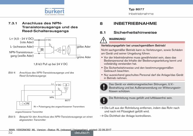
7.3.1 Anschluss des npn-Transistorausgangs und des reed-schalterausgangs
X
V DCL+ (4,5 - 24 V DC) (rote Ader)
L- (schwarze Ader)
NPN-Transistoraus-gang (weiße Ader)
Rgelbe Ader
grüne Ader
1,8 kW Pull up bei 24 V DC
Bild 4: Anschluss des NPN-Transistorausgangs und des Reed-Schalterausgangs
8077
XV DC
NPN
L-
L+
+- IN
angeschlossener Transmitter
IN = Pulseingang des angeschlossenen Transmitters
Bild 5: Beispiel für den Anschluss des NPN-Transistorausgangs an einen abgesetzten Transmitter
8 inbeTriebnAhme
8.1 sicherheitshinweise
Warnung!
Verletzungsgefahrbeiunsachgemäßembetrieb!
Nicht sachgemäßer Betrieb kann zu Verletzungen, sowie Schäden am Gerät und seiner Umgebung führen.
▶ Vor der Inbetriebnahme muss gewährleistet sein, dass das Bedienpersonal die Inhalte der Bedienungsanleitung kennt und vollständig verstanden hat.
▶ Die Sicherheitshinweise und den bestimmungsgemäßen Gebrauch beachten.
▶ Nur ausreichend geschultes Personal darf die Anlage/das Gerät in Betrieb nehmen.
Das Gerät vor elektromagnetischen Störungen, U.V.-Bestrahlung und bei Außenanwendung vor Witterungsein-flüssen schützen.
Die Rohrleitung muss gefüllt und luftblasenfrei sein.
→ Die Luft aus der Rohrleitung entfernen, indem das Rohr nach und nach mit Flüssigkeit gefüllt wird.
→ Die Dichtheit der Anlage kontrollieren.
deutsch
33
Wartung, Problemlösung
Typ 8077
9 WArTunG, problemlösunG
9.1 sicherheitshinweise
gefahr!
VerletzungsgefahrdurchhohenDruckinderAnlage! ▶ Vor dem Lösen der Prozessanschlüsse die Anlage druckfrei schalten und die Flüssigkeitszirkulation stoppen.
Verletzungsgefahrdurchstromschlag! ▶ Schalten Sie vor Beginn der Arbeiten in jedem Fall die Span-nung ab, und sichern Sie diese vor Wiedereinschalten!
▶ Beachten Sie geltende Unfallverhütungs- und Sicherheitsbe-stimmungen für elektrische Geräte!
VerletzungsgefahraufgrundderArtderflüssigkeit! ▶ Beachten Sie die Regeln, die auf dem Gebiet der Unfallverhütung und der Sicherheit in Kraft sind und die sich auf die Verwendung gefährlicher Produkte beziehen.
Verletzungsgefahrdurchhoheflüssigkeitstemperaturen! ▶ Das Gerät nur mit Schutzhandschuhen anfassen. ▶ Vor dem Lösen der Prozessanschlüsse die Flüssigkeitszirkula-tion stoppen und die Rohrleitung leeren.
▶ Leicht brennbare Materialien und Medien vom Gerät fernhalten.
Warnung!
GefahrdurchunsachgemäßeWartungsarbeiten! ▶ Wartungsarbeiten dürfen nur durch autorisiertes Fachpersonal und mit geeignetem Werkzeug durchgeführt werden!
▶ Nach einer Unterbrechung der elektrischen Versorgung ist ein definierter und kontrollierter Wiederanlauf des Prozesses zu gewährleisten.
9.2 Wartung des filters
→ Nach Durchlauf der ersten 200 Liter Flüssigkeit kontrollieren, ob der Filter Späne oder Ablagerungen enthält. Ihn erforderlichen-falls mit einem Produkt reinigen, das sich mit den Materialien verträgt, aus denen er besteht.
→ Den Filterzustand regelmäßig überprüfen, insbesondere wenn der Durchfluss der Flüssigkeit geringer wird. Ihn erforderlichen-falls mit einem Produkt reinigen, das sich mit den Materialien verträgt, aus denen er besteht.
deutsch
34
Wartung, Problemlösung
Typ 8077
9.3 Wartung des Gerätes
→ Regelmäßig den Zustand der Dichtung und der Ovalräder des Gerätes überprüfen. Vorgehen wie unter Kap. 9.4 beschrieben.
Das Gerät nur mit einem Tuch oder Lappen reinigen, der leicht mit Wasser oder mit einem Mittel befeuchtet ist, das sich mit den Werk-stoffen des Gerätes verträgt.
Wenn Sie ergänzende Informationen wünschen, wenden Sie sich bitte an Ihren Lieferanten Bürkert.
16
5
7
43
2
9
8
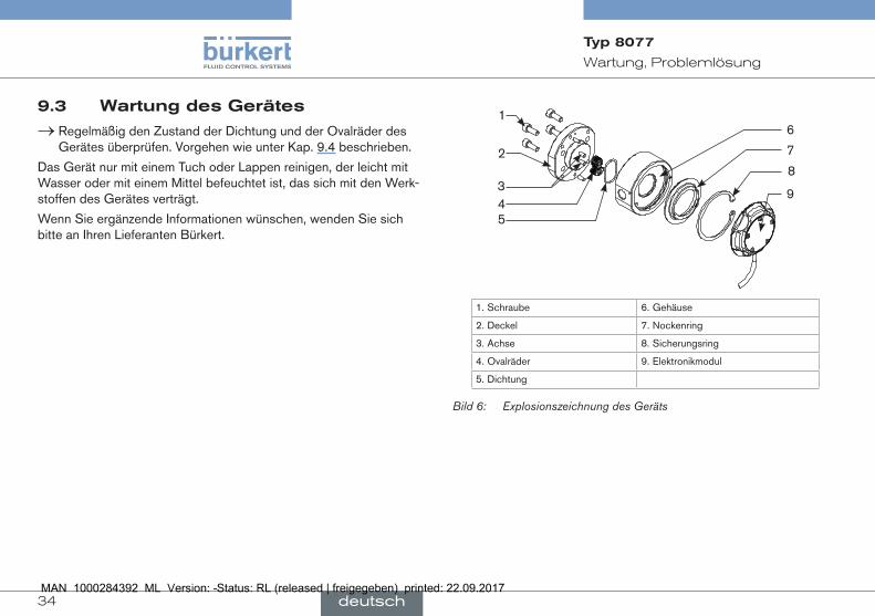
1. Schraube 6. Gehäuse
2. Deckel 7. Nockenring
3. Achse 8. Sicherungsring
4. Ovalräder 9. Elektronikmodul
5. Dichtung
Bild 6: Explosionszeichnung des Geräts
deutsch
35
Wartung, Problemlösung
Typ 8077
→ Das magnetische Rad [41] so ausrichten:
- Seite mit der Vertiefung [10],
- die glatte Seite nach hinten im Gehäuse [6].
→ Das unmagnetische Rad [42] um 90° mit Rad [41] verdreht positionieren (Siehe Bild 7).
→ Die Räder leicht per Hand drehen; sie müssen sich reibungslos bewegen.
→ Dichtung [5] zurücklegen.
→ Deckel [2] wieder auflegen.
→ Schrauben wieder über Kreuz mit einem Drehmoment von 6,5 Nm festziehen
9.5 elektronikmodul ersetzen
Das Elektronikmodul [9] enthält einen Halleffekt-Sensor und einen Reed-Schalter.
ausbau :
→ Elektronikmodul [9] um ca. 90° entgegen dem Uhrzeigersinn drehen,
→ Elektronikmodul [9] abnehmen.
aufbau :
→ Elektronikmodul [9] im Nockenring [7] positionieren,
→ Elektronikmodul [9] um 90° im Uhrzeigersinn drehen, um es zu verriegeln.
Das Elektronikmodul ist mit dem Gerät verbunden.
9.4 ovalräder ersetzen
ausbau :
→ Sicherstellen, dass die Leitung nicht mehr unter Druck ist.
→ Die Schrauben lösen und den Deckel [2] abnehmen.
→ Dichtung [5] entfernen und untersuchen; wenn nötig auswechseln.
→ Ovalräder [4] entfernen, reinigen und untersuchen; wenn nötig auswechseln.
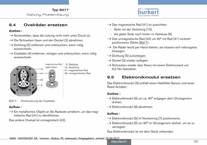
41
10
42
magnetisches Rad (glatte Seite)
6
6. Gehäuse10. Vertiefung41. magnetisches Rad42. unmagnetisches Rad
Bild 7: Positionierung der Ovalräder
aufbau :
→ Ein metallisches Objekt an die Radseite annähern, um das mag-netische Rad [41] zu identifizieren.
Das andere Ovalrad ist unmagnetisch [42].
deutsch
36
Wartung, Problemlösung
Typ 8077
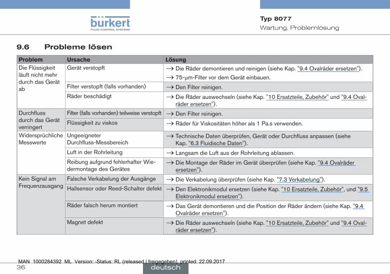
9.6 probleme lösen
Problem ursache LösungDie Flüssigkeit läuft nicht mehr durch das Gerät ab
Gerät verstopft → Die Räder demontieren und reinigen (siehe Kap. "9.4 Ovalräder ersetzen").
→ 75-µm-Filter vor dem Gerät einbauen.
Filter verstopft (falls vorhanden) → Den Filter reinigen.
Räder beschädigt → Die Räder auswechseln (siehe Kap. "10 Ersatzteile, Zubehör" und "9.4 Oval-räder ersetzen").
Durchfluss durch das Gerät verringert
Filter (falls vorhanden) teilweise verstopft → Den Filter reinigen.
Flüssigkeit zu viskos → Räder für Viskositäten höher als 1 Pa.s verwenden.
Widersprüchliche Messwerte
Ungeeigneter Durchfluss-Messbereich
→ Technische Daten überprüfen, Gerät oder Durchfluss anpassen (siehe Kap. "6.3 Fluidische Daten").
Luft in der Rohrleitung → Langsam die Luft aus der Rohrleitung ablassen.
Reibung aufgrund fehlerhafter Wie-dermontage des Gerätes
→ Die Montage der Räder im Gerät überprüfen (siehe Kap. "9.4 Ovalräder ersetzen").
Kein Signal am Frequenzausgang
Falsche Verkabelung der Ausgänge → Die Verkabelung überprüfen (siehe Kap. "7.3 Verkabelung").
Hallsensor oder Reed-Schalter defekt → Den Elektronikmodul ersetzen (siehe Kap. "10 Ersatzteile, Zubehör", und "9.5 Elektronikmodul ersetzen").
Räder falsch herum montiert → Das Gerät demontieren und die Position der Räder ändern (siehe Kap. "9.4 Ovalräder ersetzen").
Magnet defekt → Die Räder auswechseln (siehe Kap. "10 Ersatzteile, Zubehör" und "9.4 Oval-räder ersetzen").
deutsch
37
Ersatzteile, Zubehör
Typ 8077
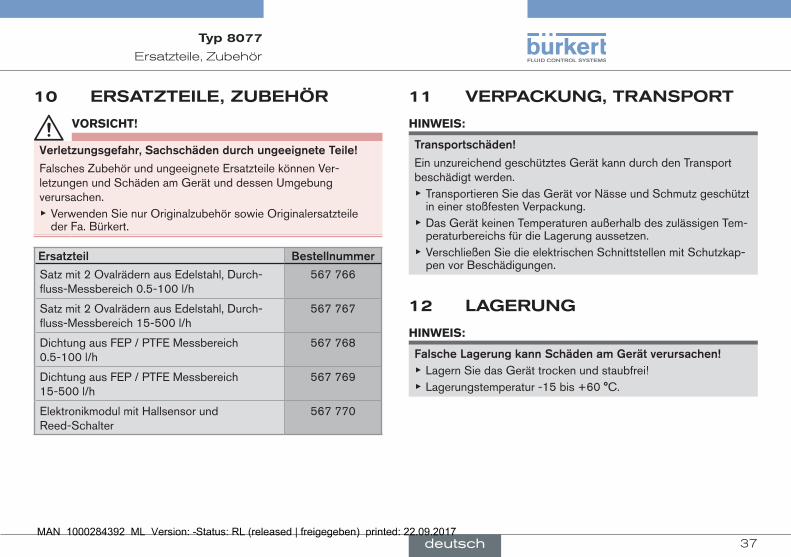
10 ersATzTeile, zubehör
VorsiCht!
Verletzungsgefahr,sachschädendurchungeeigneteteile!
Falsches Zubehör und ungeeignete Ersatzteile können Ver-letzungen und Schäden am Gerät und dessen Umgebung verursachen.
▶ Verwenden Sie nur Originalzubehör sowie Originalersatzteile der Fa. Bürkert.
ersatzteil bestellnummer
Satz mit 2 Ovalrädern aus Edelstahl, Durch-fluss-Messbereich 0.5-100 l/h
567 766
Satz mit 2 Ovalrädern aus Edelstahl, Durch-fluss-Messbereich 15-500 l/h
567 767
Dichtung aus FEP / PTFE Messbereich 0.5-100 l/h
567 768
Dichtung aus FEP / PTFE Messbereich 15-500 l/h
567 769
Elektronikmodul mit Hallsensor und Reed-Schalter
567 770
11 VerpAcKunG, TrAnsporT
hinWeis:
transportschäden!
Ein unzureichend geschütztes Gerät kann durch den Transport beschädigt werden.
▶ Transportieren Sie das Gerät vor Nässe und Schmutz geschützt in einer stoßfesten Verpackung.
▶ Das Gerät keinen Temperaturen außerhalb des zulässigen Tem-peraturbereichs für die Lagerung aussetzen.
▶ Verschließen Sie die elektrischen Schnittstellen mit Schutzkap-pen vor Beschädigungen.
12 lAGerunG
hinWeis:
falschelagerungkannschädenamGerätverursachen! ▶ Lagern Sie das Gerät trocken und staubfrei! ▶ Lagerungstemperatur -15 bis +60 °C.
deutsch
38
Entsorgung des Geräts
Typ 8077
13 enTsorGunG Des GeräTs → Gerät und Verpackung umweltgerecht entsorgen.
hinWeis!
umweltschädendurchteile,diedurchflüssigkeitenkontami-niertwurden!
▶ Geltende Entsorgungsvorschriften, nationalen Abfallbeseiti-gungsvorschriften und Umweltbestimmungen einhalten!
deutsch
39
Table des matières
Type 8077
français
27. ÀproposDecemAnuel............................................................... 40
27.1.Définitionduterme"appareil".................................................. 40
27.2.symbolesutilisés............................................................................ 40
28. utilisAtionconforme................................................................... 41
29. consiGnesDesécuritéDebAse.......................................... 41
30. informAtionsGénérAles........................................................... 43
30.1.Adressedufabricantetcontactsinternationaux........... 43
30.2.conditionsdegarantie................................................................. 43
30.3.informationssurinternet............................................................ 43
31. Description............................................................................................ 43
31.1.secteurd'application.................................................................... 43
31.2.Descriptiongénérale..................................................................... 43
31.3.Descriptiondumarquaged'identification.......................... 44
31.4.Versionsdisponibles..................................................................... 45
32. cArActéristiquestechniques............................................. 46
32.1.conditionsd'utilisation................................................................. 46
32.2.caractéristiquesmécaniques................................................... 46
32.3.caractéristiquesdufluide.......................................................... 47
32.4.caractéristiquesélectriques..................................................... 47
32.5.Dimensions........................................................................................ 48
32.6.facteurK(enimp./l)..................................................................... 48
33. instAllAtionetcâblAGeélectrique.............................. 48
33.1.consignesdesécurité................................................................. 48
33.2.recommandationsd'installation............................................. 49
33.3.câblage................................................................................................ 50
34. miseenserVice................................................................................... 51
34.1.consignesdesécurité................................................................. 51
35. mAintenAnceetDépAnnAGe..................................................... 51
35.1.consignesdesécurité................................................................. 51
35.2.entretiendufiltre............................................................................ 52
35.3.entretiendel'appareil................................................................... 52
35.4.remplacerlesrouesovales...................................................... 52
35.5.remplacerlecouvercleavecmoduleélectronique..... 53
35.6.encasdeproblème...................................................................... 54
36. piècesDerechAnGeetAccessoires.............................. 55
37. embAllAGeettrAnsport........................................................... 55
38. stocKAGe.................................................................................................. 55
39. miseAurebutDel'AppAreil.................................................................56
40
À propos de ce manuel
1 À propos De ce mAnuelCe manuel décrit le cycle de vie complet de l'appareil. Conservez-le de sorte qu'il soit accessible à tout utilisateur et à disposition de tout nouveau propriétaire.
cemanueld'utilisationcontientdesinformationsimportantesrelativesàlasécurité.
Lire ce manuel du début à la fin. Tenir compte en particulier des chapitres "Consignes de sécurité de base" et "Utilisation conforme" .
▶ Quelle que soit la version de votre appareil, ce manuel d'utilisation doit être lu et compris.
1.1 Définition du terme "appareil"
Dans ce manuel d‘utilisation, le terme "appareil" désigne toujours le débitmètre type 8077.
1.2 symboles utilisés
Danger
metengardecontreundangerimminent. ▶ Ne pas en tenir compte peut entraîner la mort ou de graves blessures.
aVertissement
metengardecontreunesituationéventuellementdangereuse.
▶ Ne pas en tenir compte peut entraîner de graves blessures, et même la mort.
attention
metengardecontreunrisqueéventuel. ▶ Ne pas en tenir compte peut entraîner des blessures légères ou de gravité moyenne.
remarque
metengardecontredesdommagesmatériels.
Conseils ou recommandations importants.
renvoie à des informations contenues dans ce manuel ou dans d'autres documents.
▶ Indique une consigne à exécuter pour éviter un danger.
→ indique une opération à effectuer.
Type 8077
français
41
Utilisation conforme
2 uTilisATion conforme
l'utilisationnonconformedel'appareilpeutprésenterdesdangerspourlespersonnes,lesinstallationsprochesetl‘environnement.
Le débitmètre type 8077 est destiné à la mesure du débit de liquides, particulièrement de liquides visqueux.
▶ Utiliser cet appareil conformément aux caractéristiques et conditions de mise en service et d'utilisation indiquées dans les documents contractuels et dans le manuel d'utilisation.
▶ Protéger cet appareil contre les perturbations électromagné-tiques, les rayons ultraviolets et, lorsqu'il est installé à l'extérieur, des effets des conditions climatiques.
▶ N'exploiter qu'un appareil en parfait état. ▶ Stocker, transporter, installer et exploiter l'appareil de façon appropriée.
▶ Utiliser cet appareil de façon conforme.
3 consiGnes De sécuriTé De bAse
Ces consignes de sécurité ne tiennent pas compte des imprévus pouvant survenir lors de l’assemblage, de l’utilisation et de l’entretien.
L'exploitant a la responsabilité de faire respecter les prescriptions de sécurité locales, également en ce qui concerne le personnel.
risquedeblessuredûàlatensionélectrique
risquedeblessuredûàlapressionélevéedansl'installation.
risquedebrûluredûàdestempératuresélevéesdufluide.
risquedeblessuredûàlanaturedufluide.
situationsdangereusesdiverses
Pour éviter toute blessure : ▶ Ne pas utiliser cet appareil pour mesurer le débit d'un gaz. ▶ Ne pas utiliser cet appareil dans une atmosphère explosive. ▶ Ne pas utiliser cet appareil dans un environnement incompatible avec les matériaux qui le composent.
▶ N’apporter aucune modification à l'appareil.
Type 8077
français
42
Consignes de sécurité de base
situationsdangereusesdiverses(suite)
Pour éviter toute blessure : ▶ Empêcher toute mise sous tension involontaire de l'installation. ▶ Seuls des professionnels formés peuvent effectuer l'installation et la maintenance.
▶ Après une coupure de l'alimentation électrique, garantir un redé-marrage défini et contrôlé du process.
▶ Respecter les règles de l'art de la technique.
remarque
l'appareilpeutêtreendommagéparlefluideencontact. ▶ Vérifier systématiquement la compatibilité chimique des maté-riaux composant l’appareil et les produits susceptibles d’entrer en contact avec celui-ci (par exemple : alcools, acides forts ou concentrés, aldéhydes, bases, esters, composés aliphatiques, cétones, aromatiques ou hydrocarbures halogénés, oxydants et agents chlorés).
remarque
éléments/composantssensiblesauxdéchargesélectrostatiques
▶ Cet appareil contient des composants électroniques sensibles aux décharges électrostatiques. Ils peuvent être endommagés lorsqu'ils sont touchés par une personne ou un objet chargé électrostatiquement. Dans le pire des cas, ils sont détruits instantanément ou tombent en panne sitôt effectuée la mise en route.
▶ Pour réduire au minimum voire éviter tout dommage dû à une décharge électrostatique, prendre toutes les précautions décrites dans la norme EN 61340-5-1.
▶ Veiller également à ne pas toucher les composants électriques sous tension.
Type 8077
français
43
Informations générales
4 informATions GénérAles
4.1 Adresse du fabricant et contacts internationaux
Le fabricant de l‘appareil peut être contacté à l‘adresse suivante :
Bürkert SAS
Rue du Giessen
BP 21
F-67220 TRIEMBACH-AU-VAL
Vous pouvez également contacter votre revendeur Bürkert.
Les adresses des filiales internationales sont disponibles sous : www.burkert.com
4.2 conditions de garantie
La condition pour bénéficier de la garantie légale est l’utilisation conforme de l‘appareil dans le respect des conditions d’utilisation spécifiées dans le présent manuel d'utilisation.
4.3 informations sur internet
Retrouvez sur internet les manuels d'utilisation et les fiches tech-niques relatifs au type 8077 sous : www.burkert.fr
5 DescripTion
5.1 secteur d'application
L'appareil permet de mesurer, grâce à ses roues ovales, le débit de liquides visqueux. Il doit être associé à un instrument déporté d'acqui-sition/conversion de la fréquence des impulsions liées à la rotation des roues ovales (voir la fiche technique du type 8077).
5.2 Description générale
5.2.1 construction
L'appareil est composé d'un raccord à roues ovales et d'un module électronique incluant un capteur à effet Hall et un interrupteur Reed.
Les roues ovales du raccord contiennent des aimants.
Toutes les versions de l'appareil présentent une sortie transistor NPN et une sortie interrupteur Reed.
Le raccordement électrique s'effectue à l'aide d'un câble à 5 fils d'un mètre de long.
Type 8077
français
44
Description
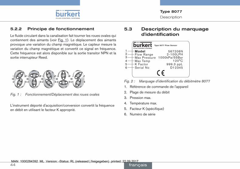
5.2.2 principe de fonctionnement
Le fluide circulant dans la canalisation fait tourner les roues ovales qui contiennent des aimants (voir Fig. 1). Le déplacement des aimants provoque une variation du champ magnétique. Le capteur mesure la variation du champ magnétique et convertit ce signal en fréquence. Cette fréquence est alors disponible sur la sortie transitor NPN et la sortie interrupteur Reed.
Fig. 1 : Fonctionnement/Déplacement des roues ovales
L'instrument déporté d'acquisition/conversion convertit la fréquence en débit en utilisant le facteur K approprié.
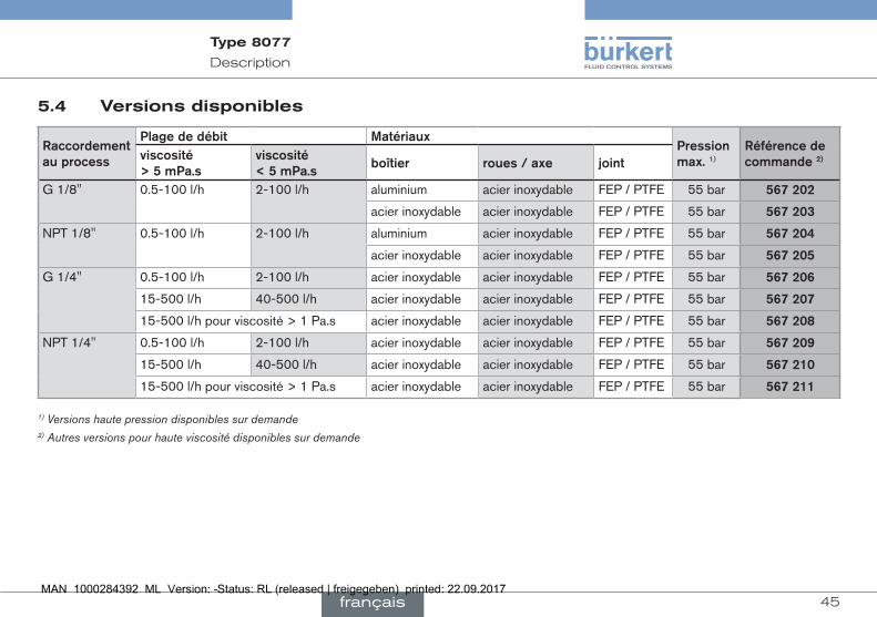
5.3 Description du marquage d'identification
12345
ModelFlow RangeMax PressureMax TempK Factor
Type 8077 Flow Sensor
567206N2-100LPH
1000kPa/55Bar120°C
999.3 ppLSerial No D123456
Fig. 2 : Marquage d'identification du débitmètre 8077
1. Référence de commande de l'appareil
2. Plage de mesure du débit
3. Pression max.
4. Température max.
5. Facteur K (spécifique)
6. Numéro de série
Type 8077
français
45
Description
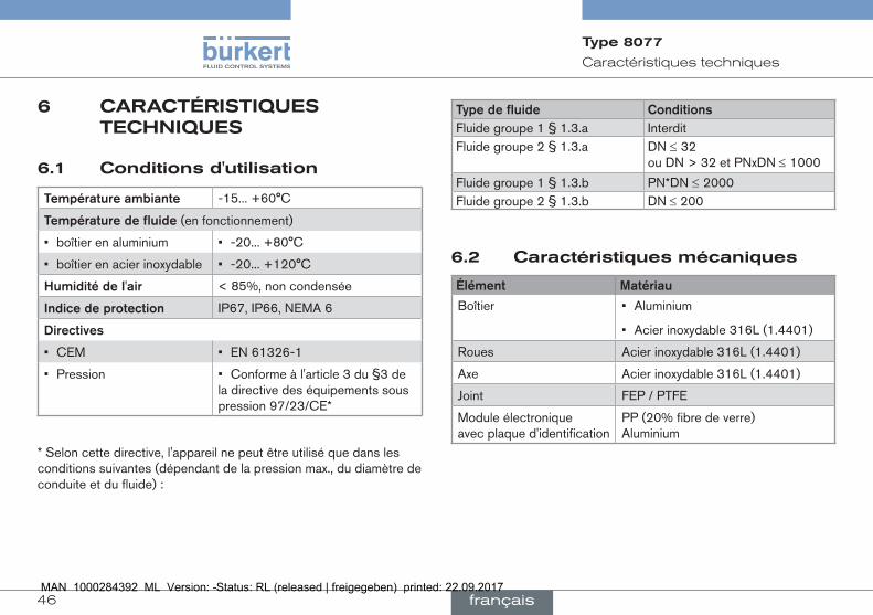
5.4 Versions disponibles
raccordementauprocess
plagededébit matériauxpressionmax.1)
référencedecommande2)viscosité
>5mpa.sviscosité<5mpa.s
boîtier roues/axe joint
G 1/8'' 0.5-100 l/h 2-100 l/h aluminium acier inoxydable FEP / PTFE 55 bar 567202
acier inoxydable acier inoxydable FEP / PTFE 55 bar 567203
NPT 1/8'' 0.5-100 l/h 2-100 l/h aluminium acier inoxydable FEP / PTFE 55 bar 567204
acier inoxydable acier inoxydable FEP / PTFE 55 bar 567205
G 1/4'' 0.5-100 l/h 2-100 l/h acier inoxydable acier inoxydable FEP / PTFE 55 bar 567206
15-500 l/h 40-500 l/h acier inoxydable acier inoxydable FEP / PTFE 55 bar 567207
15-500 l/h pour viscosité > 1 Pa.s acier inoxydable acier inoxydable FEP / PTFE 55 bar 567208
NPT 1/4'' 0.5-100 l/h 2-100 l/h acier inoxydable acier inoxydable FEP / PTFE 55 bar 567209
15-500 l/h 40-500 l/h acier inoxydable acier inoxydable FEP / PTFE 55 bar 567210
15-500 l/h pour viscosité > 1 Pa.s acier inoxydable acier inoxydable FEP / PTFE 55 bar 567211
1) Versions haute pression disponibles sur demande2) Autres versions pour haute viscosité disponibles sur demande
Type 8077
français
46
Caractéristiques techniques
6 cArAcTérisTiques Techniques
6.1 conditions d'utilisation
températureambiante -15... +60°C
températuredefluide(en fonctionnement)
• boîtier en aluminium • -20... +80°C
• boîtier en acier inoxydable • -20... +120°C
humiditédel'air < 85%, non condensée
indicedeprotection IP67, IP66, NEMA 6
Directives
• CEM • EN 61326-1
• Pression • Conforme à l'article 3 du §3 de la directive des équipements sous pression 97/23/CE*
* Selon cette directive, l'appareil ne peut être utilisé que dans les conditions suivantes (dépendant de la pression max., du diamètre de conduite et du fluide) :
typedefluide conditionsFluide groupe 1 § 1.3.a InterditFluide groupe 2 § 1.3.a DN ≤ 32
ou DN > 32 et PNxDN ≤ 1000
Fluide groupe 1 § 1.3.b PN*DN ≤ 2000Fluide groupe 2 § 1.3.b DN ≤ 200
6.2 caractéristiques mécaniques
élément matériau
Boîtier • Aluminium
• Acier inoxydable 316L (1.4401)
Roues Acier inoxydable 316L (1.4401)
Axe Acier inoxydable 316L (1.4401)
Joint FEP / PTFE
Module électronique avec plaque d'identification
PP (20% fibre de verre) Aluminium
Type 8077
français
47
Caractéristiques techniques
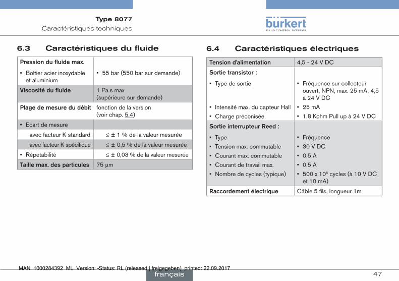
6.3 caractéristiques du fluide
pressiondufluidemax.
• Boîtier acier inoxydable et aluminium
• 55 bar (550 bar sur demande)
Viscositédufluide 1 Pa.s max (supérieure sur demande)
plagedemesuredudébit fonction de la version (voir chap. 5.4)
• Ecart de mesure
avec facteur K standard ≤ ± 1 % de la valeur mesurée
avec facteur K spécifique ≤ ± 0,5 % de la valeur mesurée
• Répétabilité ≤ ± 0,03 % de la valeur mesurée
taillemax.desparticules 75 µm
6.4 caractéristiques électriques
tensiond'alimentation 4,5 - 24 V DC
sortietransistor:
• Type de sortie
• Intensité max. du capteur Hall
• Charge préconisée
• Fréquence sur collecteur ouvert, NPN, max. 25 mA, 4,5 à 24 V DC
• 25 mA
• 1,8 Kohm Pull up à 24 V DC
sortieinterrupteurreed:
• Type
• Tension max. commutable
• Courant max. commutable
• Courant de travail max.
• Nombre de cycles (typique)
• Fréquence
• 30 V DC
• 0,5 A
• 0,5 A
• 500 x 106 cycles (à 10 V DC et 10 mA)
raccordementélectrique Câble 5 fils, longueur 1m
Type 8077
français
48
Installation et câblage électrique
6.5 Dimensions
Retrouvez ces informations dans la fiche technique du type 8077 sous : www.burkert.fr
6.6 facteur K (en imp./l)
plagededébit facteurKstandard(imp./l)0.5 - 100 l/h 100015 - 500 l/h 400
Vous pouvez utiliser le facteur K standard dans tous les cas.
→ Pour améliorer l'écart de mesure, utiliser le facteur K spécifique, marqué directement sur l'appareil (voir chap. 5.3).
Si l'appareil est raccordé à un instrument qui ne convertit pas automatiquement les facteurs K, effectuer la conversion avec l'une des formules ci-dessous :
Facteur K en imp/gallon US = facteur K en imp/l x 3,785 pour obtenir un débit en gallon US / unité de temps
Facteur K en imp/gallon UK = facteur K en imp/l x 4,546 pour obtenir un débit en gallon UK / unité de temps
7 insTAllATion eT câblAGe élecTrique
7.1 consignes de sécurité
Danger
Dangerdûàlatensionélectrique ▶ Couper l'alimentation électrique de tous les conducteurs et consigner l'alimentation électrique avant d'intervenir sur l'installation.
▶ Respecter la règlementation en vigueur en matière de pré-vention des accidents et de sécurité relative aux appareils électriques.
risquedeblessuredûàlapressionélevéedansl'installation. ▶ Stopper la circulation du fluide, couper la pression et purger la canalisation avant de desserrer les raccordements au process.
risquedeblessuredûàdestempératuresélevéesdufluide ▶ Utiliser des gants de protection pour saisir l'appareil. ▶ Stopper la circulation du fluide et purger la canalisation avant de desserrer les raccordements au process.
risquedeblessuredûàlanaturedufluide. ▶ Respecter la règlementation en vigueur en matière de préven-tion des accidents et de sécurité relative à l'utilisation de produits dangereux.
Type 8077
français
49
Installation et câblage électrique
remarque
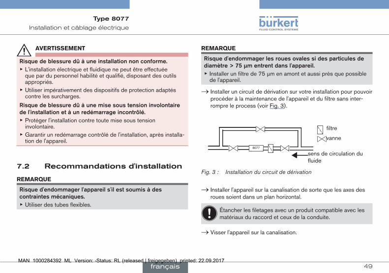
risqued'endommagerlesrouesovalessidesparticulesdediamètre>75µmentrentdansl'appareil.
▶ Installer un filtre de 75 µm en amont et aussi près que possible de l'appareil.
→ Installer un circuit de dérivation sur votre installation pour pouvoir procéder à la maintenance de l'appareil et du filtre sans inter-rompre le process (voir Fig. 3).
vanne
sens de circulation du fluide
filtre
8077
Fig. 3 : Installation du circuit de dérivation
→ Installer l'appareil sur la canalisation de sorte que les axes des roues soient dans un plan horizontal.
Étancher les filetages avec un produit compatible avec les matériaux du raccord et ceux de la conduite.
→ Visser l'appareil sur la canalisation.
aVertissement
risquedeblessuredûàuneinstallationnonconforme. ▶ L'installation électrique et fluidique ne peut être effectuée que par du personnel habilité et qualifié, disposant des outils appropriés.
▶ Utiliser impérativement des dispositifs de protection adaptés contre les surcharges.
risquedeblessuredûàunemisesoustensioninvolontairedel'installationetàunredémarrageincontrôlé.
▶ Protéger l'installation contre toute mise sous tension involontaire.
▶ Garantir un redémarrage contrôlé de l'installation, après installa-tion de l'appareil.
7.2 recommandations d'installation
remarque
risqued'endommagerl'appareils'ilestsoumisàdescontraintesmécaniques.
▶ Utiliser des tubes flexibles.
Type 8077
français
50
Installation et câblage électrique
7.3 câblage
Danger
risquedeblessurepardéchargeélectrique. ▶ Couper l'alimentation électrique de tous les conducteurs et con-signer l'alimentation électrique avant d'intervenir sur l'installation.
▶ Respecter la réglementation en vigueur en matière de pré-vention des accidents et de sécurité relative aux appareils électriques.
• Utiliser une alimentation électrique filtrée et régulée.
• Garantir l'équipotentialité de l'installation.
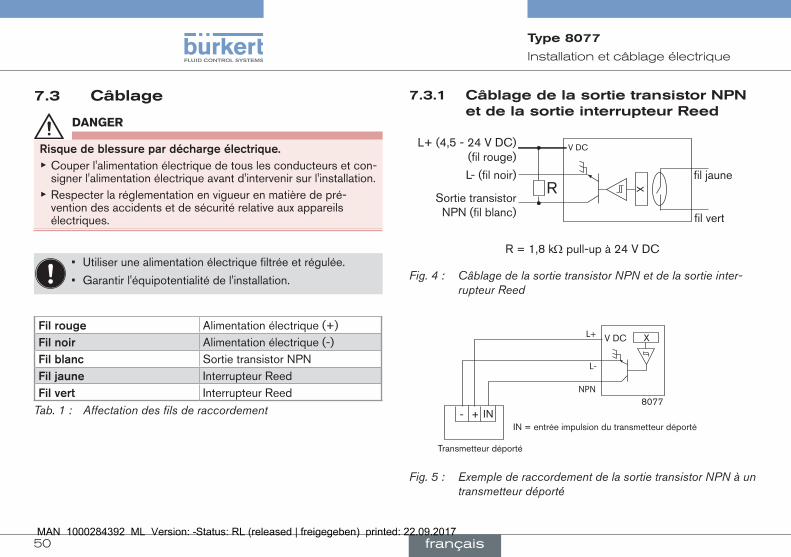
filrouge Alimentation électrique (+)filnoir Alimentation électrique (-)filblanc Sortie transistor NPNfiljaune Interrupteur Reedfilvert Interrupteur Reed
Tab. 1 : Affectation des fils de raccordement
7.3.1 câblage de la sortie transistor npn et de la sortie interrupteur reed
XV DCL+ (4,5 - 24 V DC)
(fil rouge)
L- (fil noir)
Sortie transistor NPN (fil blanc)
Rfil jaune
fil vert
R = 1,8 kW pull-up à 24 V DC
Fig. 4 : Câblage de la sortie transistor NPN et de la sortie inter-rupteur Reed
8077
XV DC
NPN
L-
L+
+- IN
Transmetteur déporté
IN = entrée impulsion du transmetteur déporté
Fig. 5 : Exemple de raccordement de la sortie transistor NPN à un transmetteur déporté
Type 8077
français
51
Mise en service
8 mise en serVice
8.1 consignes de sécurité
aVertissement
risquedeblessuredûàunemiseenservicenonconforme.
La mise en service non conforme peut entrainer des blessures et endommager l'appareil et son environnement.
▶ S'assurer avant la mise en service que le personnel qui en est chargé a lu et parfaitement compris le contenu de ce manuel.
▶ Respecter en particulier les consignes de sécurité et l'utilisation conforme.
▶ L'appareil / l'installation ne doit être mis(e) en service que par du personnel suffisamment formé.
Protéger l’appareil contre les perturbations électromagné-tiques, les rayons ultraviolets et, lorsqu’il est installé à l’exté-rieur, des effets des conditions climatiques.
La canalisation doit être remplie et exempte de bulles d'air.
→ Purger l'air de la canalisation en remplissant progressivement la canalisation en fluide.
→ Vérifier l'étanchéité de l'installation.
9 mAinTenAnce eT DépAnnAGe
9.1 consignes de sécurité
Danger
risquedeblessuredûàlapressionélevéedansl'installation. ▶ Stopper la circulation du fluide, couper la pression et purger la canalisation avant de desserrer les raccordements au process.
risquedeblessurepardéchargeélectrique. ▶ Couper et consigner l'alimentation électrique avant d'intervenir sur l'installation.
▶ Respecter la règlementation en vigueur en matière de pré-vention des accidents et de sécurité relative aux appareils électriques.
risquedeblessuredûàlanaturedufluide. ▶ Respecter la règlementation en vigueur en matière de préven-tion des accidents et de sécurité relative à l'utilisation de fluides agressifs.
risquedeblessuredûàdestempératuresélevéesdufluide ▶ Utiliser des gants de protection pour saisir l'appareil. ▶ Stopper la circulation du fluide et purger la canalisation avant de desserrer les raccordements au process.
▶ Tenir éloigné de l'appareil tout tissu et tout fluide facilement inflammable.
Type 8077
français
52
Maintenance et dépannage
aVertissement
Dangerdûàunemaintenancenonconforme. ▶ Ces travaux doivent être effectués uniquement par du personnel qualifié et habilité, disposant des outils appropriés.
▶ Après toute coupure de l'alimentation électrique, garantir un redémarrage défini ou contrôlé du process.
9.2 entretien du filtre
→ Après circulation des 200 premiers litres de fluide, vérifier que le filtre ne contient ni copeaux ni dépôts. Le nettoyer si nécessaire avec un produit compatible avec les matériaux qui le composent.
→ Vérifier régulièrement l'état du filtre, en particulier quand le débit de fluide diminue. Le nettoyer si nécessaire avec un produit compatible avec les matériaux qui le composent.
9.3 entretien de l'appareil
→ Vérifier régulièrement l'état du joint et des roues ovales de l'ap-pareil. Procéder comme décrit au chap. 9.4.
L'appareil peut être nettoyé avec un chiffon imbibé d'eau ou d'un produit compatible avec les matériaux qui le composent.
Votre fournisseur Bürkert reste à votre entière disposition pour tous renseignements complémentaires.
16
5
7
43
2
9
8
1. Vis 5. Joint
2. Couvercle 6. Corps
3. Axe 7. Came
4. Roues ovales 8. Circlip
41. Roue active (avec aimant) 9. Module électronique
42. Roue neutre (sans aimant) 10. Repère
Fig. 6 : Vue éclatée de l'appareil
9.4 remplacer les roues ovales
Démontage:
→ Vérifier que la conduite n‘est plus sous pression.
→ Desserrer les vis [1] et retirer le couvercle [2].
→ Retirer le joint [5] et vérifier l‘aspect; remplacer si nécessaire.
Type 8077
français
53
Maintenance et dépannage
9.5 remplacer le couvercle avec module électronique
Le module électronique [9] contient le capteur à effet Hall et l'inter-rupteur Reed.
Démontage:
Pour retirer le module [9] :
→ tourner le module de 1/4 de tour dans le sens inverse des aiguilles d'une montre,
→ retirer le module [9].
remontage:
Pour remonter le module [9] :
→ positionner le module [9] dans la came [7],
→ tourner le module [9] de 1/4 de tour dans le sens des aiguilles d'une montre.
Le module électronique est maintenant solidaire du reste de l'appareil.
→ Retirer les roues [4], vérifier et nettoyer; remplacer si nécessaire.
41
10
42
Roue active(face lisse)
6
Fig. 7 : Positionnement des roues ovales
remontage:
→ Identifier la roue active [41] en approchant un objet métallique de la face lisse.
L'autre roue dentée ovale est la roue neutre.
→ Replacer la roue active [41]:
- côté repère [10],
- face lisse (coté aimanté) au fond du corps [6].
→ Replacer la roue neutre [42] à 90° de la roue active [41]
→ Tourner doucement les roues avec le doigt; elles doivent tourner librement.
→ Replacer le joint [5].
→ Remettre le couvercle [2].
→ 7- Resserrer les vis [1] en croix avec un couple de serrage de 6,5 Nm
Type 8077
français
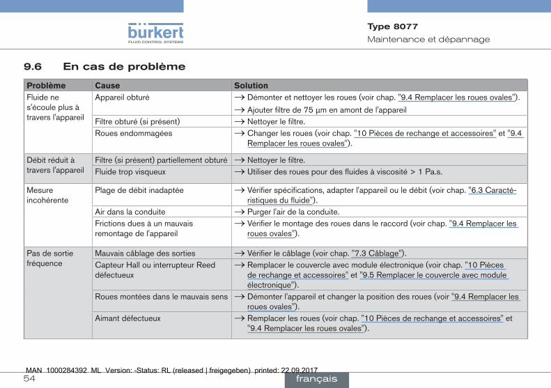
54
Maintenance et dépannage
9.6 en cas de problème
Problème Cause solutionFluide ne s'écoule plus à travers l'appareil
Appareil obturé → Démonter et nettoyer les roues (voir chap. "9.4 Remplacer les roues ovales").
→ Ajouter filtre de 75 µm en amont de l'appareilFiltre obturé (si présent) → Nettoyer le filtre.Roues endommagées → Changer les roues (voir chap. "10 Pièces de rechange et accessoires" et "9.4
Remplacer les roues ovales").
Débit réduit à travers l'appareil
Filtre (si présent) partiellement obturé → Nettoyer le filtre.Fluide trop visqueux → Utiliser des roues pour des fluides à viscosité > 1 Pa.s.
Mesure incohérente
Plage de débit inadaptée → Vérifier spécifications, adapter l'appareil ou le débit (voir chap. "6.3 Caracté-ristiques du fluide").
Air dans la conduite → Purger l'air de la conduite.Frictions dues à un mauvais remontage de l'appareil
→ Vérifier le montage des roues dans le raccord (voir chap. "9.4 Remplacer les roues ovales").
Pas de sortie fréquence
Mauvais câblage des sorties → Vérifier le câblage (voir chap. "7.3 Câblage").Capteur Hall ou interrupteur Reed défectueux
→ Remplacer le couvercle avec module électronique (voir chap. "10 Pièces de rechange et accessoires" et "9.5 Remplacer le couvercle avec module électronique").
Roues montées dans le mauvais sens → Démonter l'appareil et changer la position des roues (voir "9.4 Remplacer les roues ovales").
Aimant défectueux → Remplacer les roues (voir chap. "10 Pièces de rechange et accessoires" et "9.4 Remplacer les roues ovales").
Type 8077
français
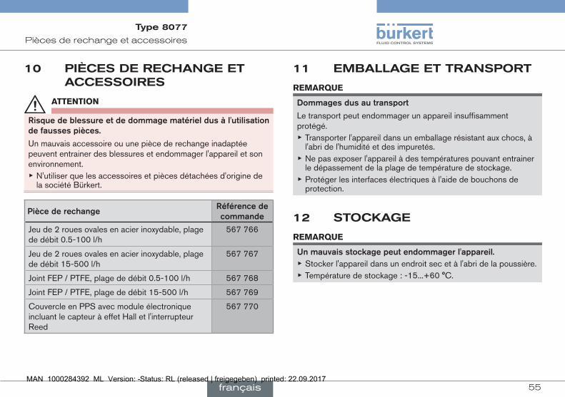
55
Pièces de rechange et accessoires
10 pièces De rechAnGe eT Accessoires
attention
risquedeblessureetdedommagematérieldusàl'utilisationdefaussespièces.
Un mauvais accessoire ou une pièce de rechange inadaptée peuvent entrainer des blessures et endommager l'appareil et son environnement.
▶ N'utiliser que les accessoires et pièces détachées d'origine de la société Bürkert.
piècederechangeréférencedecommande
Jeu de 2 roues ovales en acier inoxydable, plage de débit 0.5-100 l/h
567 766
Jeu de 2 roues ovales en acier inoxydable, plage de débit 15-500 l/h
567 767
Joint FEP / PTFE, plage de débit 0.5-100 l/h 567 768
Joint FEP / PTFE, plage de débit 15-500 l/h 567 769
Couvercle en PPS avec module électronique incluant le capteur à effet Hall et l'interrupteur Reed
567 770
11 embAllAGe eT TrAnsporT
remarque
Dommagesdusautransport
Le transport peut endommager un appareil insuffisamment protégé.
▶ Transporter l'appareil dans un emballage résistant aux chocs, à l'abri de l'humidité et des impuretés.
▶ Ne pas exposer l'appareil à des températures pouvant entrainer le dépassement de la plage de température de stockage.
▶ Protéger les interfaces électriques à l'aide de bouchons de protection.
12 sTocKAGe
remarque
unmauvaisstockagepeutendommagerl'appareil. ▶ Stocker l'appareil dans un endroit sec et à l'abri de la poussière. ▶ Température de stockage : -15...+60 °C.
Type 8077
français
56
Mise au rebut de l'appareil
13 mise Au rebuT De l'AppAreil → Éliminer l’appareil et l’emballage dans le respect de l’environnement.
remarque
Dommagesàl'environnementcauséspardespiècesconta-minéespardesfluides.
▶ Respecter les prescriptions locales ou nationales en vigueur en matière d'élimination des déchets et de protection de l'environnement.
Type 8077
français


www.burkert.com