Embed Size (px)
Citation preview
441-622-098 07/06 www.controlair.com Subject to change without notice
Type-5500 Profibus-DP
Technical Manual
Type-5500 with Profibus Technical Manual
441-622-098 07/06 www.controlair.com Subject to change without notice
Page 2
Table of Contents Type-5500 Introduction............................................................................................................................................3
Product Overview .................................................................................................................................................3 About Profibus..........................................................................................................................................................4
Overview ...............................................................................................................................................................4 TYPE-5500 Profibus Features..............................................................................................................................4 Cabling and Drop Line Lengths (as defined by Profibus specification) ............................................................4
Type-5500..................................................................................................................................................................5 Removable Miniature Electropneumatic Regulators ..........................................................................................5 Calibrating Miniature Electropneumatic Regulators..........................................................................................6 Module Configurations and Pinouts....................................................................................................................7
Factory Default Settings ...................................................................................................................................7 LED Display .....................................................................................................................................................7 Connector Types...............................................................................................................................................7 Profibus DP Communication Connector Pinout.............................................................................................8 Auxiliary Power Connector Pinout...................................................................................................................8
Network Address ..................................................................................................................................................9 Rotary Switch Settings (SW1 & SW2)...............................................................................................................9 DIP Switch Settings (SW3)............................................................................................................................. 10 Settings Example ............................................................................................................................................ 10
Power Supply Wiring Diagram............................................................................................................................11 Power Consumption ........................................................................................................................................... 12
Auxiliary Power Connector – Power Pins ...................................................................................................... 12 Power Ratings................................................................................................................................................. 12 Recommended External Fuses: ..................................................................................................................... 12
Power Consumption and External Fuse Sizing Guide...................................................................................... 13 Profibus-DP Configuration and Mapping ............................................................................................................. 14
GSD File.............................................................................................................................................................. 14 I/O Setup............................................................................................................................................................ 14 Manifold I/O Sizing Table ................................................................................................................................ 14 Bit Mapping Rules.............................................................................................................................................. 15 I/O Mapping ...................................................................................................................................................... 15
Example #1 I/O Table................................................................................................................................... 16 Diagnostics ............................................................................................................................................................. 18
LED Functions ................................................................................................................................................... 18 Appendix................................................................................................................................................................. 19
System Specifications ......................................................................................................................................... 19 Factory Default Settings ..................................................................................................................................... 19 Troubleshooting ................................................................................................................................................. 20 Glossary of Terms............................................................................................................................................... 21
Technical Support .................................................................................................................................................. 22
Type-5500 with Profibus Technical Manual
441-622-098 07/06 www.controlair.com Subject to change without notice
Page 3
Type-5500 Introduction
Product Overview
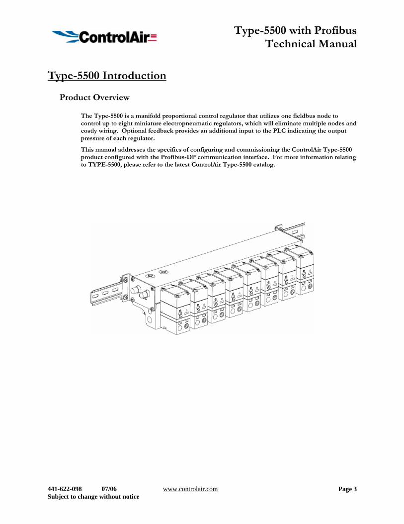
The Type-5500 is a manifold proportional control regulator that utilizes one fieldbus node to control up to eight miniature electropneumatic regulators, which will eliminate multiple nodes and costly wiring. Optional feedback provides an additional input to the PLC indicating the output pressure of each regulator.
This manual addresses the specifics of configuring and commissioning the ControlAir Type-5500 product configured with the Profibus-DP communication interface. For more information relating to TYPE-5500, please refer to the latest ControlAir Type-5500 catalog.
Type-5500 with Profibus Technical Manual
441-622-098 07/06 www.controlair.com Subject to change without notice
Page 4
About Profibus
Overview Profibus-DP is a communication protocol used to network industrial devices to eliminate labor intensive and expensive point to point wiring schemes. Siemens originally developed Profibus DP, but it is now supported by a multitude of manufacturers and the protocol standard governed by the Profibus Trade Organization (PTO).
Profibus-DP uses a 2-wire (plus shield) network and can have up to 124 nodes. The protocol can transfer a maximum of 244 bytes of data per node cycle with nine selectable communication (baud) rates of 9.6 Kbps, 19.2 Kbps, 93.75 Kbps, 187.5 Kbps, 500 Kbps, 1.5Mbps, 3 Mbps, 6 Mbps and 12 Mbps. Maximum distance depends upon baud rate and cable media type. Refer to the section below for details.
More information about Profibus can be obtained from the Profibus web site http://www.profibus.com
TYPE-5500 Profibus Features
Features Description Bus Topology Linear bus, active bus termination on both ends. Stub lines
permitted only for <= 1.5Mbit/sec baud rates. Baud Rates Supported 9.6 Kbps, 19.2 Kbps, 93.75 Kbps, 187.5 Kbps, 500 Kbps, 1.5Mbps,
3 Mbps, 6 Mbps and 12 Mbps Duplicate address detection Node address must match address in Master configuration software,
before node will enter the data exchange mode Error Correction Yes, if error detected, sender is requested to repeat the message
Address Setting options Done by internal switches
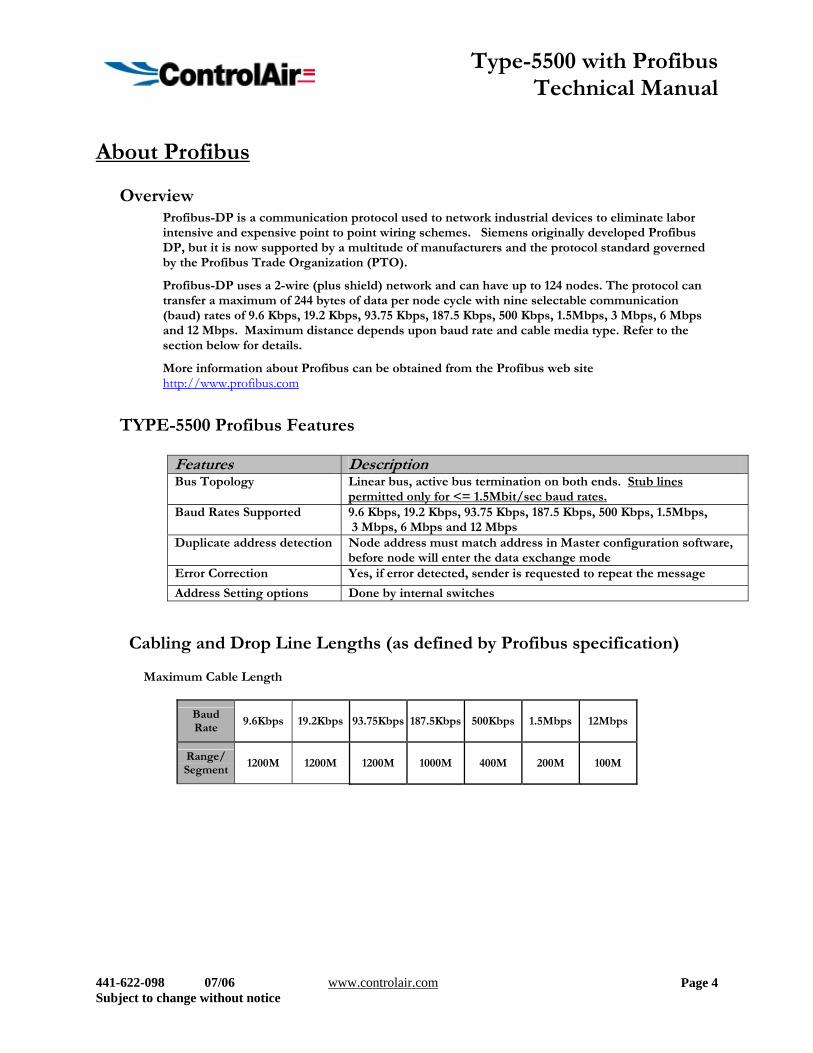
Cabling and Drop Line Lengths (as defined by Profibus specification)
Maximum Cable Length
Baud Rate
9.6Kbps 19.2Kbps 93.75Kbps 187.5Kbps 500Kbps 1.5Mbps 12Mbps
Range/ Segment
1200M 1200M 1200M 1000M 400M 200M 100M
Type-5500 with Profibus Technical Manual
441-622-098 07/06 www.controlair.com Subject to change without notice
Page 5
Type-5500
Removable Miniature Electropneumatic Regulators
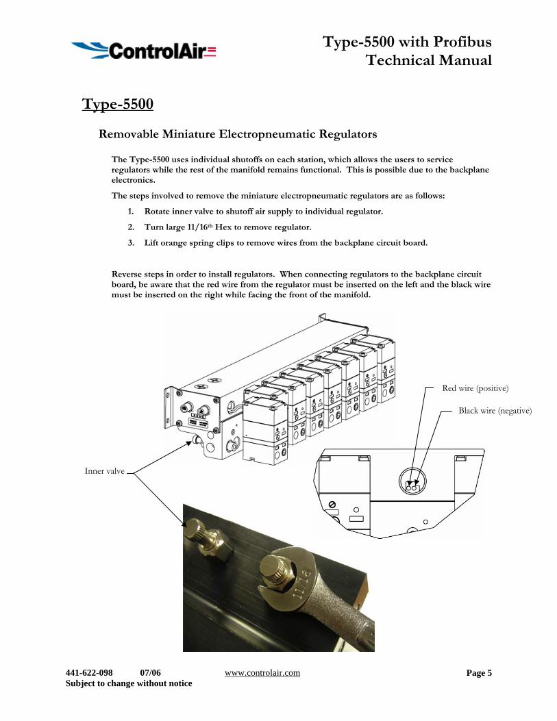
The Type-5500 uses individual shutoffs on each station, which allows the users to service regulators while the rest of the manifold remains functional. This is possible due to the backplane electronics.
The steps involved to remove the miniature electropneumatic regulators are as follows:
1. Rotate inner valve to shutoff air supply to individual regulator.
2. Turn large 11/16th Hex to remove regulator.
3. Lift orange spring clips to remove wires from the backplane circuit board.
Reverse steps in order to install regulators. When connecting regulators to the backplane circuit board, be aware that the red wire from the regulator must be inserted on the left and the black wire must be inserted on the right while facing the front of the manifold.
Inner valve
Red wire (positive)
Black wire (negative)
Type-5500 with Profibus Technical Manual
441-622-098 07/06 www.controlair.com Subject to change without notice
Page 6
Calibrating Miniature Electropneumatic Regulators
Calibration
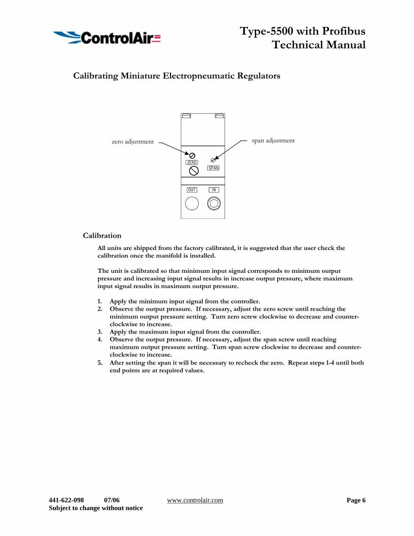
All units are shipped from the factory calibrated, it is suggested that the user check the calibration once the manifold is installed. The unit is calibrated so that minimum input signal corresponds to minimum output pressure and increasing input signal results in increase output pressure, where maximum input signal results in maximum output pressure. 1. Apply the minimum input signal from the controller. 2. Observe the output pressure. If necessary, adjust the zero screw until reaching the
minimum output pressure setting. Turn zero screw clockwise to decrease and counter-clockwise to increase.
3. Apply the maximum input signal from the controller. 4. Observe the output pressure. If necessary, adjust the span screw until reaching
maximum output pressure setting. Turn span screw clockwise to decrease and counter-clockwise to increase.
5. After setting the span it will be necessary to recheck the zero. Repeat steps 1-4 until both end points are at required values.
span adjustment zero adjustment
Type-5500 with Profibus Technical Manual
441-622-098 07/06 www.controlair.com Subject to change without notice
Page 7
Module Configurations and Pinouts
Factory Default Settings Type Value Description
Node Address 126 Node address Diagnostics Disabled Diagnostic Reporting is turned off
Diagnostic Mask 0 Determines which outputs are enabled for diagnostic reporting
Fail Safe Mode Disabled Fail Safe Mode Disabled Fail Safe Data 0 Determines if Fail Safe Data is 1 or 0 for an output.
LED Display
Connector Types
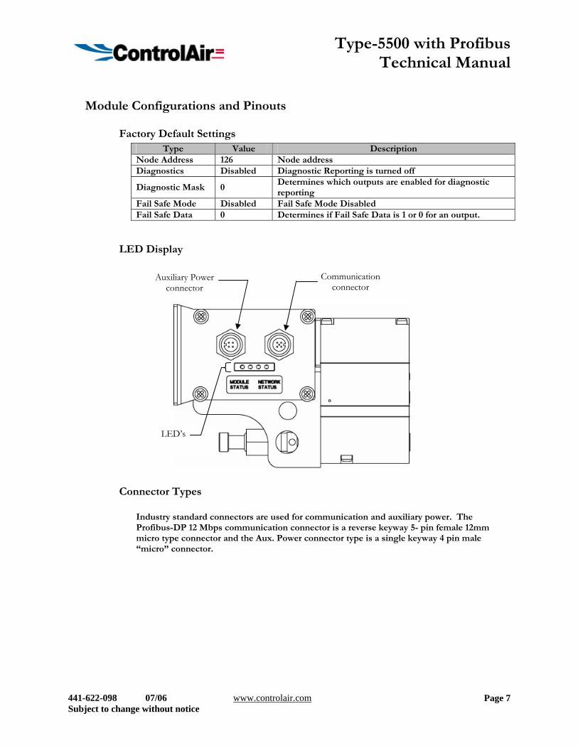
Industry standard connectors are used for communication and auxiliary power. The Profibus-DP 12 Mbps communication connector is a reverse keyway 5- pin female 12mm micro type connector and the Aux. Power connector type is a single keyway 4 pin male “micro” connector.
Auxiliary Power connector
Communication connector
LED’s
Type-5500 with Profibus Technical Manual
441-622-098 07/06 www.controlair.com Subject to change without notice
Page 8
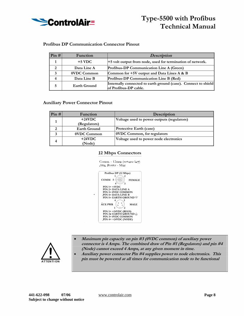
Profibus DP Communication Connector Pinout
Pin # Function Description 1 +5 VDC +5 volt output from node, used for termination of network.
2 Data Line A Profibus-DP Communication Line A (Green) 3 0VDC Common Common for +5V output and Data Lines A & B 4 Data Line B Profibus-DP Communication Line B (Red)
5 Earth Ground Internally connected to earth ground (case). Connect to shield of Profibus-DP cable.
Auxiliary Power Connector Pinout
Pin # Function Description
1 +24VDC
(Regulators) Voltage used to power outputs (regulators)
2 Earth Ground Protective Earth (case) 3 0VDC Common 0VDC Common, for regulators
4 +24VDC (Node)
Voltage used to power node electronics
• Maximum pin capacity on pin #3 (0VDC common) of auxiliary power
connector is 4 Amps. The combined draw of Pin #1 (Regulators) and pin #4 (Node) cannot exceed 4 Amps, at any given moment in time.
• Auxiliary power connector Pin #4 supplies power to node electronics. This pin must be powered at all times for communication node to be functional
ATTENTION
!
FEMALE
Profibus DP (12 Mbps)
MALE
PIN 1= +5VDC
PIN 4= DATA LINE BPIN 3= 0VDC COMMONPIN 2= DATA LINE A
PIN 5= EARTH GROUND
AUX PWR1
4
2
3
5
4
1
3
2
PIN 1= +24VDC (REGS)
PIN 4= +24VDC (NODE)PIN 3= 0VDC COMMONPIN 2= EARTH GROUND
Type-5500 with Profibus Technical Manual
441-622-098 07/06 www.controlair.com Subject to change without notice
Page 9
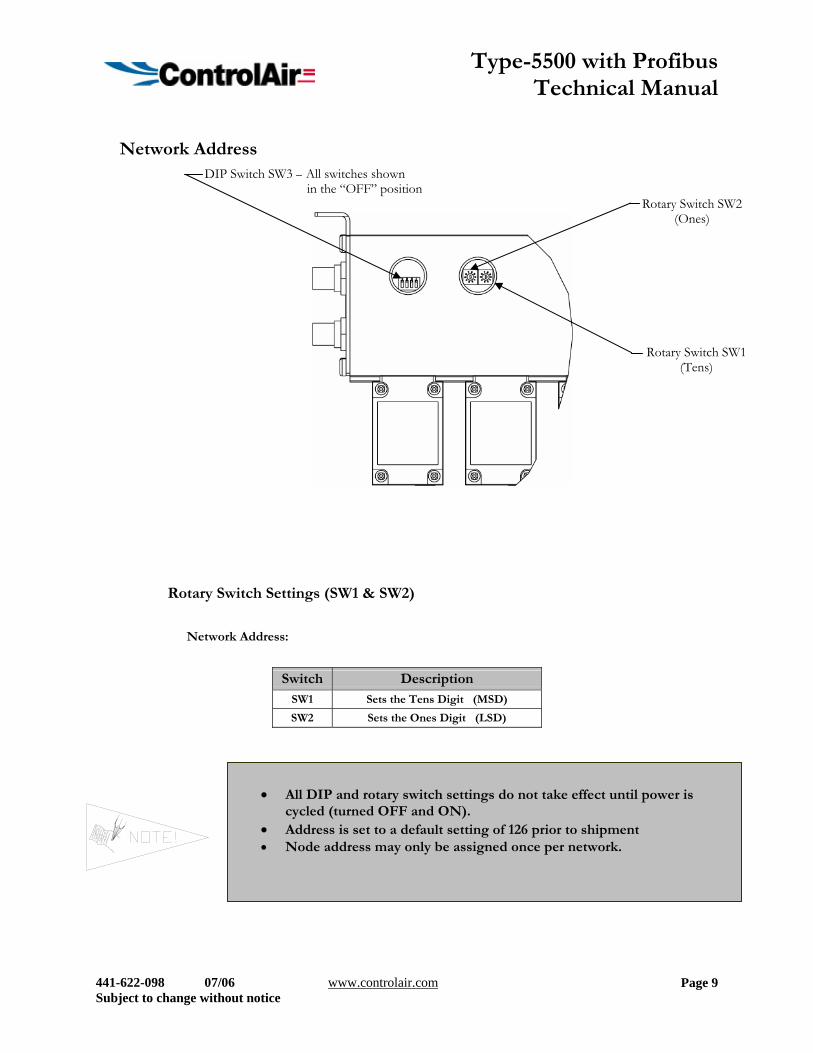
Network Address
Rotary Switch Settings (SW1 & SW2)
Network Address:
Switch Description
SW1 Sets the Tens Digit (MSD)
SW2 Sets the Ones Digit (LSD)
• All DIP and rotary switch settings do not take effect until power is
cycled (turned OFF and ON). • Address is set to a default setting of 126 prior to shipment • Node address may only be assigned once per network.
DIP Switch SW3 – All switches shown in the “OFF” position
Rotary Switch SW2(Ones)
Rotary Switch SW1(Tens)
Type-5500 with Profibus Technical Manual
441-622-098 07/06 www.controlair.com Subject to change without notice
Page 10
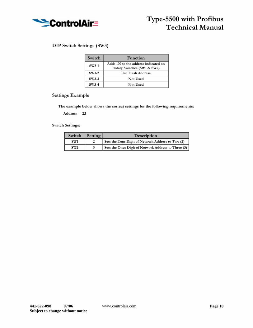
DIP Switch Settings (SW3)
Switch Function
SW3-1 Adds 100 to the address indicated on
Rotary Switches (SW1 & SW2) SW3-2 Use Flash Address
SW3-3 Not Used
SW3-4 Not Used
Settings Example
The example below shows the correct settings for the following requirements:
Address = 23
Switch Settings:
Switch Setting Description SW1 2 Sets the Tens Digit of Network Address to Two (2)
SW2 3 Sets the Ones Digit of Network Address to Three (3)
Type-5500 with Profibus Technical Manual
441-622-098 07/06 www.controlair.com Subject to change without notice
Page 11
Electrical Connections
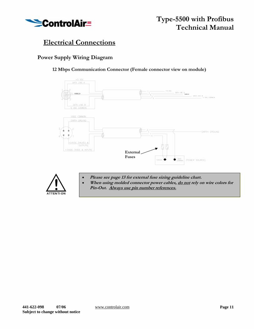
Power Supply Wiring Diagram
12 Mbps Communication Connector (Female connector view on module)
External Fuses
SHIELD SHIELD
External Fuses
• Please see page 13 for external fuse sizing guideline chart. • When using molded connector power cables, do not rely on wire colors for
Pin-Out. Always use pin number references. ATTENTION
!
Type-5500 with Profibus Technical Manual
441-622-098 07/06 www.controlair.com Subject to change without notice
Page 12
Power Consumption
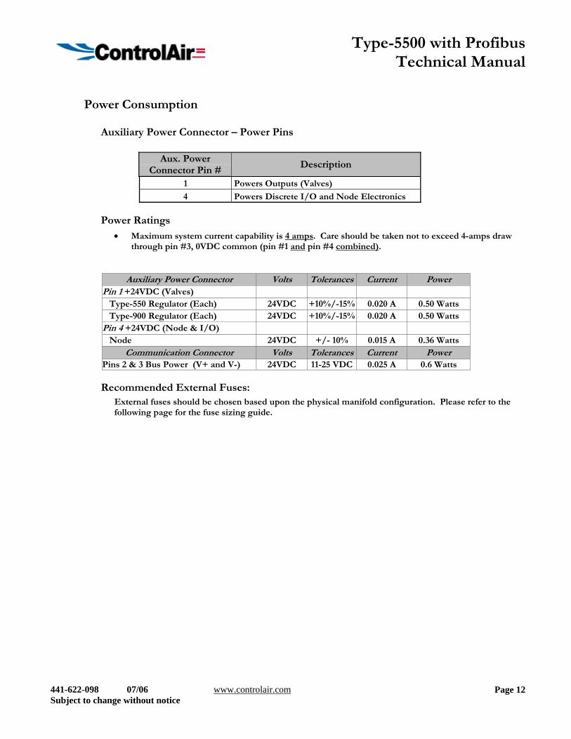
Auxiliary Power Connector – Power Pins
Aux. Power Connector Pin #
Description
1 Powers Outputs (Valves)
4 Powers Discrete I/O and Node Electronics
Power Ratings • Maximum system current capability is 4 amps. Care should be taken not to exceed 4-amps draw
through pin #3, 0VDC common (pin #1 and pin #4 combined).
Auxiliary Power Connector Volts Tolerances Current Power Pin 1 +24VDC (Valves) Type-550 Regulator (Each) 24VDC +10%/-15% 0.020 A 0.50 Watts Type-900 Regulator (Each) 24VDC +10%/-15% 0.020 A 0.50 Watts Pin 4 +24VDC (Node & I/O) Node 24VDC +/- 10% 0.015 A 0.36 Watts
Communication Connector Volts Tolerances Current Power Pins 2 & 3 Bus Power (V+ and V-) 24VDC 11-25 VDC 0.025 A 0.6 Watts
Recommended External Fuses: External fuses should be chosen based upon the physical manifold configuration. Please refer to the following page for the fuse sizing guide.
Type-5500 with Profibus Technical Manual
441-622-098 07/06 www.controlair.com Subject to change without notice
Page 13
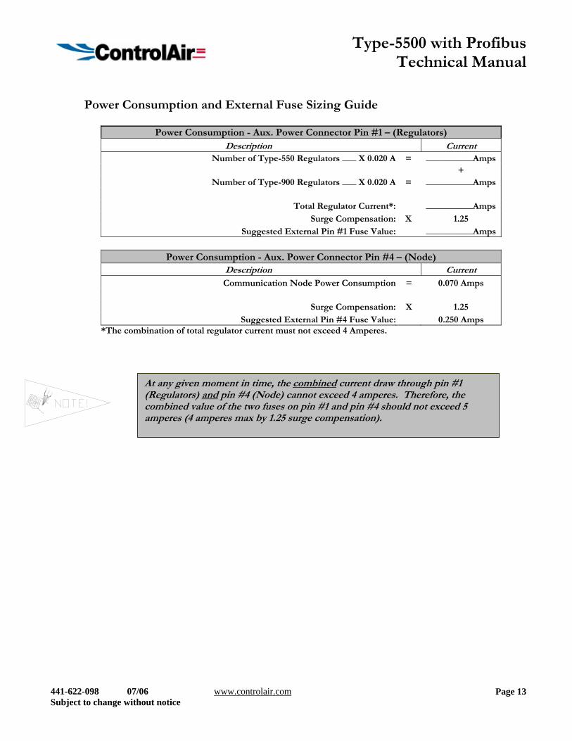
Power Consumption and External Fuse Sizing Guide
Power Consumption - Aux. Power Connector Pin #1 – (Regulators) Description Current
Number of Type-550 Regulators ___ X 0.020 A = __________Amps +
Number of Type-900 Regulators ___ X 0.020 A = __________Amps
Total Regulator Current*: __________AmpsSurge Compensation: X 1.25
Suggested External Pin #1 Fuse Value: __________Amps
Power Consumption - Aux. Power Connector Pin #4 – (Node) Description Current
Communication Node Power Consumption = 0.070 Amps
Surge Compensation: X 1.25 Suggested External Pin #4 Fuse Value: 0.250 Amps
*The combination of total regulator current must not exceed 4 Amperes.
At any given moment in time, the combined current draw through pin #1 (Regulators) and pin #4 (Node) cannot exceed 4 amperes. Therefore, the combined value of the two fuses on pin #1 and pin #4 should not exceed 5 amperes (4 amperes max by 1.25 surge compensation).
Type-5500 with Profibus Technical Manual
441-622-098 07/06 www.controlair.com Subject to change without notice
Page 14
Profibus-DP Configuration and Mapping
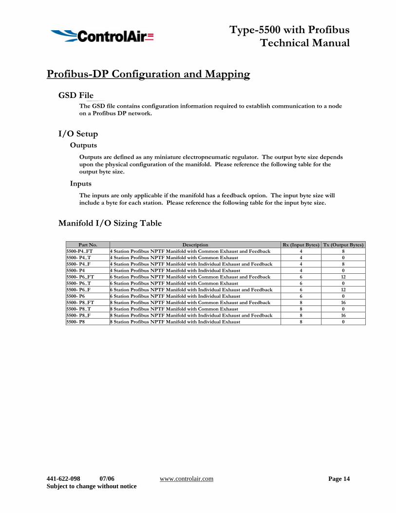
GSD File The GSD file contains configuration information required to establish communication to a node on a Profibus DP network.
I/O Setup Outputs
Outputs are defined as any miniature electropneumatic regulator. The output byte size depends upon the physical configuration of the manifold. Please reference the following table for the output byte size.
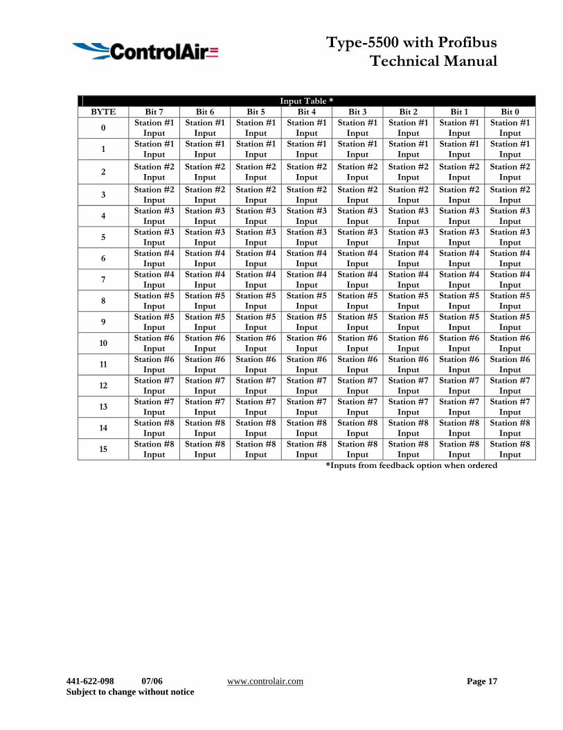
Inputs
The inputs are only applicable if the manifold has a feedback option. The input byte size will include a byte for each station. Please reference the following table for the input byte size.
Manifold I/O Sizing Table
Part No. Description Rx (Input Bytes) Tx (Output Bytes)5500-P4_FT 4 Station Profibus NPTF Manifold with Common Exhaust and Feedback 4 8 5500- P4_T 4 Station Profibus NPTF Manifold with Common Exhaust 4 0 5500- P4_F 4 Station Profibus NPTF Manifold with Individual Exhaust and Feedback 4 8 5500- P4 4 Station Profibus NPTF Manifold with Individual Exhaust 4 0 5500- P6_FT 6 Station Profibus NPTF Manifold with Common Exhaust and Feedback 6 12 5500- P6_T 6 Station Profibus NPTF Manifold with Common Exhaust 6 0 5500- P6_F 6 Station Profibus NPTF Manifold with Individual Exhaust and Feedback 6 12 5500- P6 6 Station Profibus NPTF Manifold with Individual Exhaust 6 0 5500- P8_FT 8 Station Profibus NPTF Manifold with Common Exhaust and Feedback 8 16 5500- P8_T 8 Station Profibus NPTF Manifold with Common Exhaust 8 0 5500- P8_F 8 Station Profibus NPTF Manifold with Individual Exhaust and Feedback 8 16 5500- P8 8 Station Profibus NPTF Manifold with Individual Exhaust 8 0
Type-5500 with Profibus Technical Manual
441-622-098 07/06 www.controlair.com Subject to change without notice
Page 15
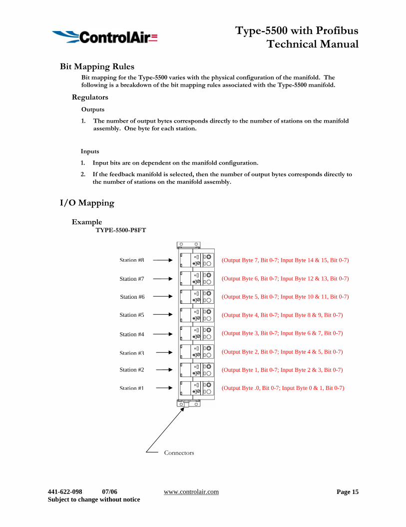
Bit Mapping Rules Bit mapping for the Type-5500 varies with the physical configuration of the manifold. The following is a breakdown of the bit mapping rules associated with the Type-5500 manifold.
Regulators
Outputs
1. The number of output bytes corresponds directly to the number of stations on the manifold assembly. One byte for each station.
Inputs
1. Input bits are on dependent on the manifold configuration.
2. If the feedback manifold is selected, then the number of output bytes corresponds directly to the number of stations on the manifold assembly.
I/O Mapping
Example TYPE-5500-P8FT
Station #7
Station #8
Station #5
Station #6
Station #3
Station #4
Station #2
Station #1 (Output Byte .0, Bit 0-7; Input Byte 0 & 1, Bit 0-7)
Connectors
(Output Byte 1, Bit 0-7; Input Byte 2 & 3, Bit 0-7)
(Output Byte 2, Bit 0-7; Input Byte 4 & 5, Bit 0-7)
(Output Byte 3, Bit 0-7; Input Byte 6 & 7, Bit 0-7)
(Output Byte 4, Bit 0-7; Input Byte 8 & 9, Bit 0-7)
(Output Byte 5, Bit 0-7; Input Byte 10 & 11, Bit 0-7)
(Output Byte 6, Bit 0-7; Input Byte 12 & 13, Bit 0-7)
(Output Byte 7, Bit 0-7; Input Byte 14 & 15, Bit 0-7)
Type-5500 with Profibus Technical Manual
441-622-098 07/06 www.controlair.com Subject to change without notice
Page 16
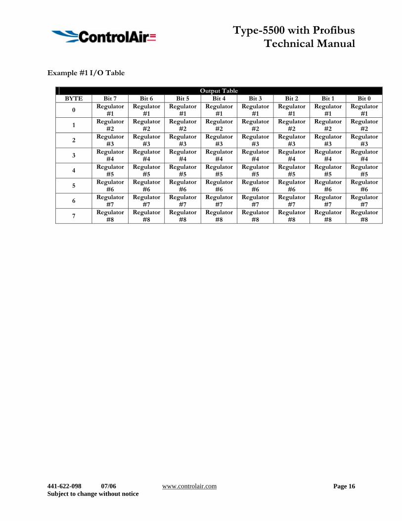
Example #1 I/O Table
Output Table BYTE Bit 7 Bit 6 Bit 5 Bit 4 Bit 3 Bit 2 Bit 1 Bit 0
0 Regulator
#1 Regulator
#1 Regulator
#1 Regulator
#1 Regulator
#1 Regulator
#1 Regulator
#1 Regulator
#1
1 Regulator
#2 Regulator
#2 Regulator
#2 Regulator
#2 Regulator
#2 Regulator
#2 Regulator
#2 Regulator
#2
2 Regulator
#3 Regulator
#3 Regulator
#3 Regulator
#3 Regulator
#3 Regulator
#3 Regulator
#3 Regulator
#3
3 Regulator
#4 Regulator
#4 Regulator
#4 Regulator
#4 Regulator
#4 Regulator
#4 Regulator
#4 Regulator
#4
4 Regulator
#5 Regulator
#5 Regulator
#5 Regulator
#5 Regulator
#5 Regulator
#5 Regulator
#5 Regulator
#5
5 Regulator
#6 Regulator
#6 Regulator
#6 Regulator
#6 Regulator
#6 Regulator
#6 Regulator
#6 Regulator
#6
6 Regulator
#7 Regulator
#7 Regulator
#7 Regulator
#7 Regulator
#7 Regulator
#7 Regulator
#7 Regulator
#7
7 Regulator
#8 Regulator
#8 Regulator
#8 Regulator
#8 Regulator
#8 Regulator
#8 Regulator
#8 Regulator
#8
Type-5500 with Profibus Technical Manual
441-622-098 07/06 www.controlair.com Subject to change without notice
Page 17
Input Table *
BYTE Bit 7 Bit 6 Bit 5 Bit 4 Bit 3 Bit 2 Bit 1 Bit 0
0 Station #1
Input Station #1
Input Station #1
Input Station #1
Input Station #1
Input Station #1
Input Station #1
Input Station #1
Input
1 Station #1
Input Station #1
Input Station #1
Input Station #1
Input Station #1
Input Station #1
Input Station #1
Input Station #1
Input
2 Station #2
Input Station #2
Input Station #2
Input Station #2
Input Station #2
Input Station #2
Input Station #2
Input Station #2
Input
3 Station #2
Input Station #2
Input Station #2
Input Station #2
Input Station #2
Input Station #2
Input Station #2
Input Station #2
Input
4 Station #3
Input Station #3
Input Station #3
Input Station #3
Input Station #3
Input Station #3
Input Station #3
Input Station #3
Input
5 Station #3
Input Station #3
Input Station #3
Input Station #3
Input Station #3
Input Station #3
Input Station #3
Input Station #3
Input
6 Station #4
Input Station #4
Input Station #4
Input Station #4
Input Station #4
Input Station #4
Input Station #4
Input Station #4
Input
7 Station #4
Input Station #4
Input Station #4
Input Station #4
Input Station #4
Input Station #4
Input Station #4
Input Station #4
Input
8 Station #5
Input Station #5
Input Station #5
Input Station #5
Input Station #5
Input Station #5
Input Station #5
Input Station #5
Input
9 Station #5
Input Station #5
Input Station #5
Input Station #5
Input Station #5
Input Station #5
Input Station #5
Input Station #5
Input
10 Station #6
Input Station #6
Input Station #6
Input Station #6
Input Station #6
Input Station #6
Input Station #6
Input Station #6
Input
11 Station #6
Input Station #6
Input Station #6
Input Station #6
Input Station #6
Input Station #6
Input Station #6
Input Station #6
Input
12 Station #7
Input Station #7
Input Station #7
Input Station #7
Input Station #7
Input Station #7
Input Station #7
Input Station #7
Input
13 Station #7
Input Station #7
Input Station #7
Input Station #7
Input Station #7
Input Station #7
Input Station #7
Input Station #7
Input
14 Station #8
Input Station #8
Input Station #8
Input Station #8
Input Station #8
Input Station #8
Input Station #8
Input Station #8
Input
15 Station #8
Input Station #8
Input Station #8
Input Station #8
Input Station #8
Input Station #8
Input Station #8
Input Station #8
Input *Inputs from feedback option when ordered
Type-5500 with Profibus Technical Manual
441-622-098 07/06 www.controlair.com Subject to change without notice
Page 18
Diagnostics
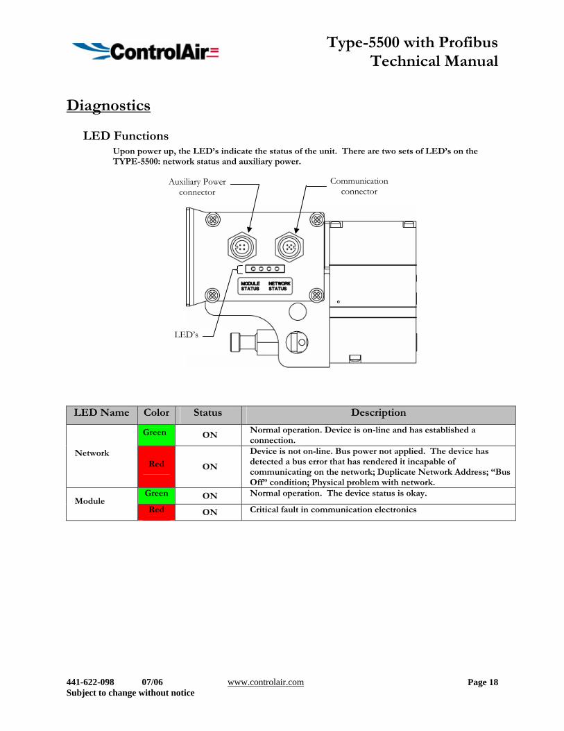
LED Functions Upon power up, the LED’s indicate the status of the unit. There are two sets of LED’s on the TYPE-5500: network status and auxiliary power.
LED Name Color Status Description
Green ON Normal operation. Device is on-line and has established a connection.
Network Red ON
Device is not on-line. Bus power not applied. The device has detected a bus error that has rendered it incapable of communicating on the network; Duplicate Network Address; “Bus Off” condition; Physical problem with network.
Green ON Normal operation. The device status is okay. Module
Red ON Critical fault in communication electronics
Auxiliary Power connector
Communication connector
LED’s
Type-5500 with Profibus Technical Manual
441-622-098 07/06 www.controlair.com Subject to change without notice
Page 19
Appendix
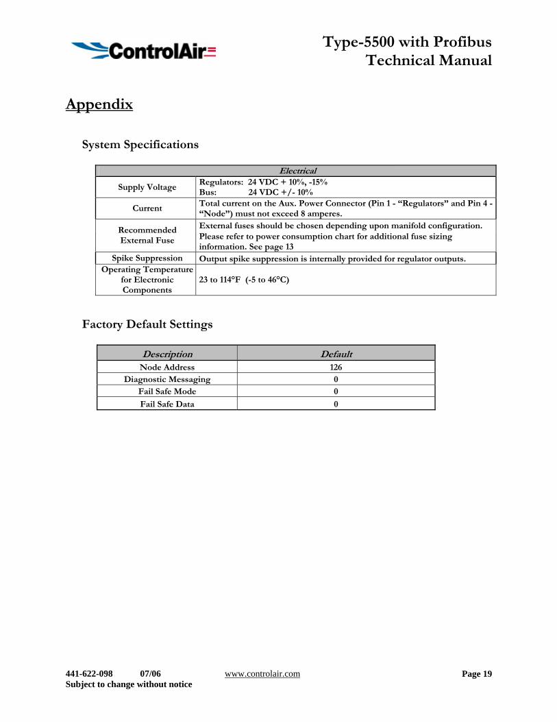
System Specifications
Electrical
Supply Voltage Regulators: 24 VDC + 10%, -15% Bus: 24 VDC +/- 10%
Current Total current on the Aux. Power Connector (Pin 1 - “Regulators” and Pin 4 - “Node”) must not exceed 8 amperes. External fuses should be chosen depending upon manifold configuration. Recommended
External Fuse Please refer to power consumption chart for additional fuse sizing information. See page 13
Spike Suppression Output spike suppression is internally provided for regulator outputs. Operating Temperature
for Electronic Components
23 to 114°F (-5 to 46°C)
Factory Default Settings
Description Default Node Address 126
Diagnostic Messaging 0 Fail Safe Mode 0
Fail Safe Data 0
Type-5500 with Profibus Technical Manual
441-622-098 07/06 www.controlair.com Subject to change without notice
Page 20
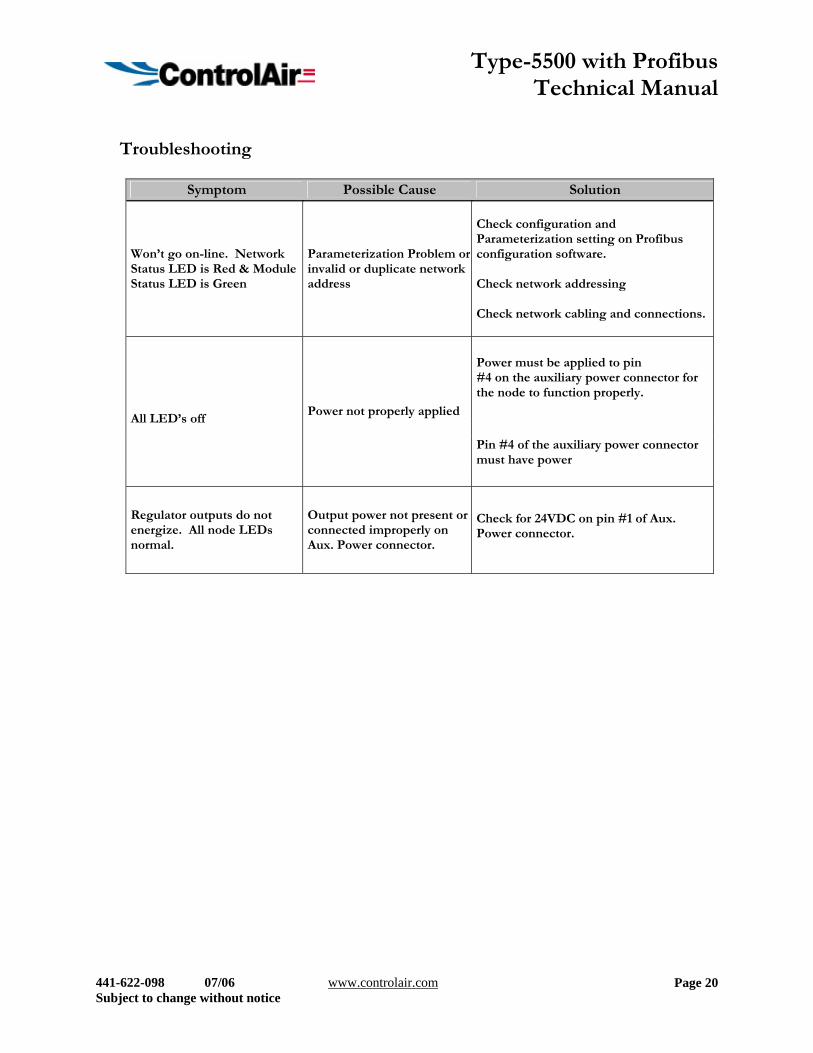
Troubleshooting
Symptom Possible Cause Solution
Won’t go on-line. Network Status LED is Red & Module Status LED is Green
Parameterization Problem or invalid or duplicate network address
Check configuration and Parameterization setting on Profibus configuration software. Check network addressing Check network cabling and connections.
Power must be applied to pin #4 on the auxiliary power connector for the node to function properly.
Pin #4 of the auxiliary power connector must have power
All LED’s off
Power not properly applied
Regulator outputs do not energize. All node LEDs normal.
Output power not present or connected improperly on Aux. Power connector.
Check for 24VDC on pin #1 of Aux. Power connector.
Type-5500 with Profibus Technical Manual
441-622-098 07/06 www.controlair.com Subject to change without notice
Page 21
Glossary of Terms The following is a list and description of common terms and symbols used throughout this document: Bit Smallest unit of digital information either a “0” or “1” Bit mapping Chart showing which bit is connected to which physical input or output point Byte 8 bits (1/2 word) Ground This term is used to indicate an earth ground GSD file A text file, which contains specific product information, definitions of product capabilities and configurable
parameters. I/O Any combination of Inputs and Outputs Word 2 Bytes (16 bits)

Type-5500 with Profibus Technical Manual
441-622-098 07/06 www.controlair.com Subject to change without notice
Page 22
Technical Support
For technical support, contact your local ControlAir distributor. Additional assistance is available from ControlAir Inc. at (603) 886-9400 and ask for Technical Support.
Issues relating to network set-up, PLC programming, sequencing, software related functions, etc… should be handled with the appropriate product vendor.