Embed Size (px)
Citation preview

U.S.D.A. Forest Service National Technology And Development Center, San Dimas
Apparatus Body Only Specification Type 4 Fire Engine, Model 428U/448U – Supersedes August 2015 Page 1
Type 4 Fire Engine — Model 428U/448U — Apparatus Body Only Specification Issue Date: February 2016
Supersedes: August 2015

U.S.D.A. Forest Service National Technology And Development Center, San Dimas
Apparatus Body Only Specification Type 4 Fire Engine, Model 428U/448U – Supersedes August 2015 Page 2
Table of Contents Record of Revisions 7
1 — General 9 1.1 Government Provided Chassis 9 1.2 NFPA 1906 Compliance 9 1.3 Weight Requirements 9 1.4 Tilt Test 9 1.5 Ramp Break-Over Angle 9 1.6 Brand Name or Equivalent Products 9
2 — Chassis Electrical Requirements 10 2.1 Chassis Electrical Additional Equipment and Modifications 10 2.2 Battery Master Switch 10 2.3 “Battery On” Indicator Light 10 2.4 Electronics Control Module Programming 10 2.5 Back Up Alarm 11 2.6 Map Light 11 2.7 “Pump Running” Warning Indicator 11 2.8 Ground Lights 11 2.9 Antennas 11 2.10 Radio Pre-Wire 11 2.11 Auxiliary Lighting 11
3 — Traffic Warning Systems 13 3.1 Warning Systems Installed 13 3.2 Electronic Siren 13 3.3 Speaker 13 3.4 Upper Zone A/B/D Lightbar 13 3.5 Upper Zone B/C/D Warning Beacons 14 3.6 Lower Zone A Warning Lights 14 3.7 Forward Lower Zone B and D Warning Lights 14 3.8 Midship Lower Zone B and D Warning Lights 14 3.9 Aft Lower Zone B and D Warning Lights 15 3.10 Lower Zone C Warning Lights 15 3.11 Air Horn 15 3.12 Headlight Flasher 15
4 — Chassis Additions and Modifications 16 4.1 Additional Equipment 16 4.2 Apparatus Fluid Types and Quantities 16 4.3 Seating Capacity 16 4.4 Seat Belts 16 4.5 Seat Belt Warning 16 4.6 Vehicle Height Warning 17 4.7 Final Stage Manufacturer Vehicle Certification 17

U.S.D.A. Forest Service National Technology And Development Center, San Dimas
Apparatus Body Only Specification Type 4 Fire Engine, Model 428U/448U – Supersedes August 2015 Page 3
4.8 Noise Hazard Warning 17 4.9 Air Filter Ember Protection Screen Warning 17 4.10 Cab Console 17 4.11 Center Console Aft Storage 18 4.12 Front Tow Hooks 18 4.13 Rear Tow Eyes 18 4.14 Front Bumper Extension 18 4.15 Hose Storage Tray 19 4.16 Front Fenders, Rubber 19 4.17 Mud Flaps 19 4.18 Cab Steps, Batteries and Air Tanks 19 4.19 Exhaust System 19 4.20 Vertical Exhaust 19 4.21 Heat Protection 20 4.22 Air Line, Fuel Hose, Electrical Harness and Connector Protection 20 4.23 Cabin Air Ember Guard 20
5 — Apparatus Body Description 21 5.1 Body Design 21 5.2 Body Construction 21 5.3 Body Subframe 21 5.4 Body Material 22 5.5 Body Mounting 22 5.6 Walkways/Drip Moldings 22 5.7 Walking Surfaces, Top of Water Tank 23 5.8 Vertical Surfaces 23 5.9 Rear Step 23 5.10 Rear Step Warning 23 5.11 Rear Stairs 23 5.12 Compartmentation 24 5.13 Driver's Side Compartments 25 5.14 Spare Tire Compartment 25 5.15 Spare Tire Winch System 26 5.16 Passenger's Side Compartments 26 5.17 Rear Seat Storage Compartment 27 5.18 Compartment Doors - Aluminum Overlap Type 28 5.19 Door Latches and Hardware 28 5.20 Door Hold Open Devices 29 5.21 Compartment Floor Mats 30 5.22 Tool Bracket Mounting Channels 30 5.23 Adjustable Shelf Channels 30 5.24 Compartment Shelves 31 5.25 Slide-Out Compartment Tray 31 5.26 Fenders and Wheel Wells 31 5.27 Chock Block Storage Compartments 32
U.S.D.A. Forest Service National Technology And Development Center, San Dimas
Apparatus Body Only Specification Type 4 Fire Engine, Model 428U/448U – Supersedes August 2015 Page 4
5.28 Body Scuff Guards 32 5.29 Stainless Steel Body Trim 32 5.30 Hard Suction Storage 32 5.31 Rear Cab Step Storage 33 5.32 Dunnage Compartment 33 5.33 Top Storage Compartment 33 5.34 Pump and Plumbing Enclosure Railing 33
6 — Pump and Plumbing 34 6.1 Pump and Plumbing Accessories Provided 34 6.2 Auxiliary Pump 34 6.3 Pump Specifications 34 6.4 Pump and Plumbing Enclosure 35 6.5 Low Voltage Monitor 36 6.6 Pump Panel Lights 36
7 — Valves, Controls, Gauges and Plumbing Requirements 37 7.1 Items Provided 37 7.2 Main Pump Discharge and Intake Plumbing 37 7.3 Master Drain 37 7.4 Truck Identification and Pump Performance Plate 38 7.5 Pump Operating Instruction Plate 38 7.6 Test Gauge Connections 38 7.7 Winterization Port 38 7.8 Pump Panel Labeling 39 7.9 Master Discharge Pressure Gauge 39 7.10 Master Intake Pressure Gauge 39 7.11 Pump Cooler/By-Pass 39 7.12 Automatic Pump Override 40 7.13 Stainless Intake Strainer 40 7.14 Discharge Locations 40 7.15 Intake Locations 41 7.16 Direct Tank Fill/Drain 41 7.17 Tank to Pump Line 41 7.18 Pump to Tank Line 41 7.19 Water Tank Sight Gauge 42 7.20 Water Tank Level Electronic Gauge 42 7.21 Foam Tank Sight Tube 42 7.22 Priming Pump 42 7.23 Booster Hose Reels 43 7.24 Foam Proportioning System 43 7.25 Pump Performance Test and Certification 44
8 — Water Tank 45 8.1 Construction 45 8.2 Clean Out Plug 46

U.S.D.A. Forest Service National Technology And Development Center, San Dimas
Apparatus Body Only Specification Type 4 Fire Engine, Model 428U/448U – Supersedes August 2015 Page 5
8.3 Tank Capacity 46 8.4 Foam Tank 46
9 — Body Electrical Requirements 47 9.1 Apparatus Body Electrical Components 47 9.2 Electrical Equipment 47 9.3 Rear DOT Lighting 47 9.4 Tail Lights, Brake Lights 47 9.5 Turn Signal Lights 47 9.6 Back Up Lights 47 9.7 License Plate Light and Bracket 47 9.8 Rear Upper Marker Lights 48 9.9 Cluster/Clearance Lights and Reflectors 48 9.10 Rear Directional Light Bar 48 9.11 Flood Lights 48 9.12 Compartment Lights 49 9.13 Compartment Door Switches 49
10 — Electrical System Performance Test, Low-Voltage 50 10.1 Requirement for Test 50 10.2 Test Sequence 50 10.3 Reserve Capacity Test 50 10.4 Alternator Performance Test at Idle 50 10.5 Alternator Performance Test at Full Load 50 10.6 Low Voltage Alarm Test 51 10.7 Documentation 51
11 — Apparatus Finish 52 11.1 Body Finish Procedure 52 11.2 Apparatus Body Color 52 11.3 Chassis Finish 52 11.4 Striping 52 11.5 Cab and Body Lettering and Striping 53 11.6 Truck Identification Plate 54
12 — Equipment 55 12.1 Equipment Provided 55 12.2 Manuals and Drawings 55 12.3 Road Kit 55 12.4 Wheel Chocks 55 12.5 Hydrant Wrench Holder 55 12.6 Booster Hose Nozzle Clip and Holder 56 12.7 Cargo Tie Downs 56
13 — Warranty Provisions 57 13.1 Fifteen Year Apparatus Warranty 57 13.2 Water Tank Warranty 57

U.S.D.A. Forest Service National Technology And Development Center, San Dimas
Apparatus Body Only Specification Type 4 Fire Engine, Model 428U/448U – Supersedes August 2015 Page 6
14 — Standard Vehicle Marking Diagram 58

U.S.D.A. Forest Service National Technology And Development Center, San Dimas
Apparatus Body Only Specification Type 4 Fire Engine, Model 428U/448U – Supersedes August 2015 Page 7
Record of Revisions
Date Revision Summary September 2010 • Initial Release January 2011 • Revision April 2014 • Added Table of Contents
• Added Record of Revisions • Added ramp break-over angle requirement • Added dimming requirement to battery on light • Reduced number of antenna bases from four to two • Clarified radio pre-wire requirements • Added auxiliary lighting • Deleted rear pedestal seating • Updated console switch requirements • Clarified console map storage requirements • Added stainless side rail requirements on top of body,
each side • Revised rear bumper/step requirements • Added rear seat base enclosure requirement • Clarified rear vertical handrail requirements • Deleted requirements for fuel can and drip torch mounts • Added interior dimensions to rear cab step storage • Increased size of dunnage compartment • Changed length of hard suction hose storage from 8 to
8.5 inches • Added railing above pump engine enclosure • Revised auxiliary fire pump specifications • Added requirement for pump engine exhaust routing • Clarified truck identification and pump performance plate
requirements • Changed master drain valve from air actuated to a
manual hand wheel • Updated pressure gauge requirements • Specified that tank to pump valve is open when pushed in • Clarified primer connection requirements • Added requirement for 4-way guide on driver’s side hose
reel • Clarified hose reel guide requirement on passenger side • Updated rear directional light bar requirements • Added nozzle bracket and rubber cup mount for booster
hose reels • Added requirement for cargo d-rings on top of body • Revised warranty to fifteen years • Added standard vehicle marking drawing
August 2015 • Updated format • Added specification for inline check valve on foam system • Added brand name or equivalent products specification
February 2016 • Updated format

U.S.D.A. Forest Service National Technology And Development Center, San Dimas
Apparatus Body Only Specification Type 4 Fire Engine, Model 428U/448U – Supersedes August 2015 Page 8
Date Revision Summary • Modified rear, under-seat specification
Future Revisions • This space reserved for future revisions

U.S.D.A. Forest Service National Technology And Development Center, San Dimas
Apparatus Body Only Specification Type 4 Fire Engine, Model 428U/448U – Supersedes August 2015 Page 9
1 — General
1.1 Government Provided Chassis
1.1.1 The apparatus body described in this specification shall be mounted on a Government-furnished cab and chassis. The Government-furnished cab and chassis shall be picked up by the apparatus manufacturer at the designated locations. The apparatus manufacturer shall be liable for all loss and damage to Government-furnished cab and chassis until the completion and final acceptance of all work and the return of the completed apparatus to the Government.
1.2 NFPA 1906 Compliance
1.2.1 The apparatus described in this specification shall be compliant with the requirements of NFPA 1906, latest edition, except where noted.
1.3 Weight Requirements
1.3.1 The in-service weight shall not exceed 90% of the front axle GAWR and 20,000 lbs. on the rear axle when:
• fully loaded with water, foam, and fuel • with 250 pounds per seat, and • 2300 pounds of equipment evenly distributed in the storage compartments.
1.4 Tilt Test
1.4.1 The apparatus shall be tested at the estimated in-service weight in accordance with NFPA 1906.
1.5 Ramp Break-Over Angle
1.5.1 The ramp break-over angle shall be maintained with the installation of the fire package.
1.6 Brand Name or Equivalent Products
1.6.1 Products equivalent to the brand name components specified herein shall be approved in writing by the Government prior to contract award and documented in the resultant contract.

U.S.D.A. Forest Service National Technology And Development Center, San Dimas
Apparatus Body Only Specification Type 4 Fire Engine, Model 428U/448U – Supersedes August 2015 Page 10
2 — Chassis Electrical Requirements
2.1 Chassis Electrical Additional Equipment and Modifications
2.1.1 The apparatus chassis shall be equipped with a heavy-duty 12 volt direct current (VDC) negative ground electrical system. The electrical system shall include all parts, components, switches, relays, wiring, and other devices required to assure complete, consistent and proper operation of the completed apparatus.
2.1.2 All lights shall comply with Federal Government Codes for vehicles of this size. These lights shall include headlamps and front turn signals with hazard switch, cab marker and clearance lights, back up lights, stop-turn-tail and license plate lights.
2.1.3 All switches for the warning lights and other electrical equipment shall be mounted on a switch panel located on the cab center console. The switches shall be functionally laid out, properly identified, and shall be located within easy reach of both the driver and the officer. The warning light system shall have a “master” switch, which shall allow for the pre-selection of all warning lights. All switches shall be of a heavy duty design.
2.1.4 The following additional electrical equipment shall be installed on, and modifications performed to, the specified cab and chassis by the apparatus builder:
2.2 Battery Master Switch
2.2.1 One battery cutoff switch shall be provided in the cab. The switch shall be a Cole Hersee™ brand, Model #M-2484-16, or equivalent, with a Model #82065 switch plate “Off/On” label, or equivalent. The switch shall be rated for 175 amps continuous duty and 800 amps intermittent duty. The switch shall be located on the floorboard to the left side of the driver’s seat and placed as far aft as possible to protect against accidental actuation.
2.3 “Battery On” Indicator Light
2.3.1 One “Battery On” indicator light, with a green lens, shall be provided on the dashboard in the cab interior within view of the driver’s seating position. This light shall illuminate anytime the battery switch is turned to the “ON” position and the brightness shall dim automatically when the chassis headlights are turned on. The indicator light shall be labeled “Battery On.”
2.4 Electronics Control Module Programming
2.4.1 The cab and chassis electronics control module shall be programmed as required to allow the use of the original equipment manufacturer’s cruise control feature as a manually-controlled fast idle.
U.S.D.A. Forest Service National Technology And Development Center, San Dimas
Apparatus Body Only Specification Type 4 Fire Engine, Model 428U/448U – Supersedes August 2015 Page 11
2.5 Back Up Alarm
2.5.1 One solid state back up alarm shall be provided at the rear of the apparatus and shall be protected from impact and debris. The back-up alarm shall be wired to the reverse circuit of the transmission, and shall provide an audible alarm to the rear of the apparatus when reverse gear is selected. The alarm shall have a volume of 87 to 112 decibels while in operation.
2.6 Map Light
2.6.1 One flexible goose neck, high-intensity map light shall be provided and mounted on the officer’s side of the cab center console. A switch for the map light shall be located on the cab center console. The light shall include a diffuser to prevent glare at night.
2.7 “Pump Running” Warning Indicator
2.7.1 A “Pump Running” indicator light shall be provided on the cab center console, located center at the top, or the most forward position. The indicator shall be illuminated when the pump is in the override mode and the system is pressurized. The indicator light shall be permanently labeled “Pump/Auto.”
2.8 Ground Lights
2.8.1 Four 4-inch diameter clear L.E.D. lights shall be provided under the chassis steps, ground-facing, two on each side. The lights shall be wired to the cab door switches and a switch on the cab center console.
2.9 Antennas
2.9.1 Two antenna bases shall be supplied and mounted on the cab roof as specified. The antenna cables shall be routed to the cab interior, terminating at the location of radio mounting bracket.
2.10 Radio Pre-Wire
2.10.1 The cab center console interior shall be wired with battery power, battery ground, ignition switched power, and radio rebroadcast wires to the siren or PA, and labeled to simplify USFS radio installation. The wiring shall allow the radio to be wired “hot” so the radio is powered when the master body disconnect switch turned off. Exposed positive terminals shall be covered by a protective boot or otherwise protected from inadvertent contact.
2.11 Auxiliary Lighting
2.11.1 A pair of white L.E.D. auxiliary lights shall be installed in the center bumper cutout mounted to the front surface of the bumper hose storage tray, on either side of the license plate location and shall be capable of being adjusted for both elevation and azimuth. The distance between the two lights shall be maximized. Each light shall

U.S.D.A. Forest Service National Technology And Development Center, San Dimas
Apparatus Body Only Specification Type 4 Fire Engine, Model 428U/448U – Supersedes August 2015 Page 12
produce a minimum of 3000 lumens, and be equipped with a diffused lens capable of projecting light with a flood pattern. The maximum size of each light shall be 3.25 inches tall by 3.25 inches wide by 3.25 inches deep and shall be equipped with an integral mounting bracket and wiring harness pigtail with connector. OEM chassis wiring and dash switch shall be used for installation if so equipped; otherwise the lights shall be installed with a relay and dash-mounted switch. The mounting fasteners used for these lights shall not damage hose stored in the bumper hose tray. The dash switch shall be labeled “AUXILIARY LIGHTS, OFF HIGHWAY USE ONLY. Rigid Industries™ Dually D2® diffusion lights or equivalent shall be installed.
U.S.D.A. Forest Service National Technology And Development Center, San Dimas
Apparatus Body Only Specification Type 4 Fire Engine, Model 428U/448U – Supersedes August 2015 Page 13
3 — Traffic Warning Systems
3.1 Warning Systems Installed
3.1.1 The following traffic warning systems shall be provided and installed on the completed apparatus by the apparatus builder:
3.2 Electronic Siren
3.2.1 One Federal Signal™ brand, Model #PA300-MSC, or equivalent, electronic siren controller shall be provided and mounted in the cab center console in a location convenient to both the driver and the officer. The siren shall have four basic siren tones: manual, wail, yelp and hi-lo, as well as an electronic air horn, radio rebroadcast capability, and a public address system.
3.2.2 The siren shall also feature the TAP II® instant yelp function and shall be capable of 58, 100, or 200 watt operation. The siren shall have a hard wired, noise canceling microphone for P.A. use, and shall be wired to the specified speaker.
3.3 Speaker
3.3.1 One Code 3™ brand, Model #Z100, or equivalent, 100 watt speaker shall be provided and mounted behind the OEM cutout in the driver’s side of the chassis front bumper. The speaker shall be wired to the specified electronic siren controller.
3.4 Upper Zone A/B/D Lightbar
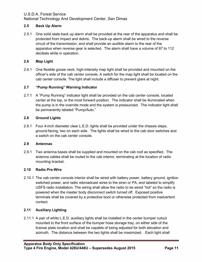
3.4.1 One L.E.D. lightbar shall installed on the cab roof, facing forward. The light bar shall be 55 inches wide. L.E.D. lighting locations and filter placement shall conform to the diagrams in this section (below) and consist of six flashing L.E.D. modules; one at each corner and two forward-facing. The lightbar shall also contain two forward-facing steady burning L.E.D. modules. The light bar shall have all red lenses or filters. A Whelen™ brand Freedom IV® L.E.D. lightbar part number F4W2RRRR-USFS34WT, or equivalent meets this requirement.
3.4.2 The light bar shall be permanently mounted to the cab roof and wired to the “Lightbar” switch in the cab center console.
3.4.3 Diagram — L.E.D. Lighting Locations and Flashing/Steady Configuration

U.S.D.A. Forest Service National Technology And Development Center, San Dimas
Apparatus Body Only Specification Type 4 Fire Engine, Model 428U/448U – Supersedes August 2015 Page 14
3.4.4 Diagram — Lightbar Filter Locations and Colors
3.4.5 Lightbar Locations and Colors
3.5 Upper Zone B/C/D Warning Beacons
3.5.1 Two Whelen™ brand, Model #RB6TRP, or equivalent, rotating beacons, with red domes, shall be provided at the upper rear corners of the body, one on each side. The beacons shall be wired to the “Warning Lights” switch located on the cab center console.
3.6 Lower Zone A Warning Lights
3.6.1 Two Whelen™ brand, 700 Series, or equivalent, red L.E.D. warning lights, with mounting flanges, shall be provided and mounted in the lower outboard corners of the cab grille, forward-facing, one on each side. The lights shall be wired to the “Warning Lights” switch located on the cab center console.
3.7 Forward Lower Zone B and D Warning Lights
3.7.1 Two Whelen™ brand, 700 Series, or equivalent, red L.E.D. warning lights, with mounting flanges, shall be provided and mounted on the sides of the chassis tilt hood, as low and as far forward as possible, side-facing, one on each side. The lights shall be wired to the “Warning Lights” switch located on the cab center console.
3.8 Midship Lower Zone B and D Warning Lights
3.8.1 Two Whelen™ brand, 600 Series, or equivalent, red L.E.D. warning lights, with mounting flanges, shall be provided and mounted forward of the rear wheel well opening, side-facing, one on each side. The lights shall be wired to the “Warning Lights” switch located on the cab center console.

U.S.D.A. Forest Service National Technology And Development Center, San Dimas
Apparatus Body Only Specification Type 4 Fire Engine, Model 428U/448U – Supersedes August 2015 Page 15
3.9 Aft Lower Zone B and D Warning Lights
3.9.1 Two Whelen™ brand, 600 Series, or equivalent, red L.E.D. warning lights, with mounting flanges, shall be provided at the lower rear corners of the body, side-facing, one on each side. The lights shall be wired to the “Warning Lights” switch located on the cab center console.
3.10 Lower Zone C Warning Lights
3.10.1 Two Whelen brand, 600 Series, or equivalent, L.E.D. warning lights shall be provided at the lower rear of the body, vertically in line with, and directly above the back-up lights, rear-facing, one on each side. The lights shall be wired to the “Warning Lights” switch located on the cab center console.
3.11 Air Horn
3.11.1 One Buell™ brand, Model #1063, or equivalent, 15-inch air horn shall be provided and installed behind the OEM cutout in the passenger’s side of the chassis front bumper. One foot switch shall be provided on the driver’s side cab floor, and one momentary push-button switch shall be provided on the forward corner of the officer’s side top surface of the cab center console.
3.12 Headlight Flasher
3.12.1 One Whelen™ brand, Model #UHF 2150A, or equivalent, solid-state headlight flasher shall be installed and wired for daytime operation. The flasher shall be a multipurpose type with a high beam-activated cut out option. The flasher shall be wired to the “Wig Wag” switch on the cab center console, through the parking brake valve, so that it is disabled when the parking brake is applied.
U.S.D.A. Forest Service National Technology And Development Center, San Dimas
Apparatus Body Only Specification Type 4 Fire Engine, Model 428U/448U – Supersedes August 2015 Page 16
4 — Chassis Additions and Modifications
4.1 Additional Equipment
4.1.1 The following additional equipment shall be installed on, and modifications performed to the specified cab and chassis by the apparatus manufacturer:
4.2 Apparatus Fluid Types and Quantities
4.2.1 A permanently-mounted label, showing the recommended fluid types and quantities for the apparatus chassis and associated components, shall be provided in the apparatus cab interior near the driver’s seating position.
4.2.2 This label shall list the recommended fluid types and quantities for the following components:
• Chassis Engine Lubricant • Chassis Engine Coolant • Chassis Power Steering Fluid • Chassis Transmission Fluid • Chassis Transfer Case Lubricant • Chassis Drive Axle Lubricant • Pump Gearbox Lubricant
4.3 Seating Capacity
4.3.1 A warning label, listing the seating capacity of the completed apparatus, shall be provided in the apparatus cab interior. This label shall be located so that it is visible from all seating positions.
4.3.2 This apparatus shall have a seating capacity of five personnel.
4.4 Seat Belts
4.4.1 3-point shoulder harness type seat belts shall be provided on all four outboard seating positions. The center rear seating position shall have a two-point lap belt type seat belt.
4.4.2 All seatbelts shall be red or orange in color.
4.5 Seat Belt Warning
4.5.1 A warning label, stating: “DANGER- Personnel Must Be Seated And Seat Belts Must Be Fastened While Vehicle Is In Motion Or DEATH OR SERIOUS INJURY MAY RESULT,” shall be provided in the apparatus cab interior. This label shall be located so that it is visible from all seating positions.
U.S.D.A. Forest Service National Technology And Development Center, San Dimas
Apparatus Body Only Specification Type 4 Fire Engine, Model 428U/448U – Supersedes August 2015 Page 17
4.6 Vehicle Height Warning
4.6.1 A warning label, listing the overall height, length, and GVWR of the completed apparatus, shall be provided in the apparatus cab interior. This label shall be located so that it is visible from the driver’s seating position.
4.7 Final Stage Manufacturer Vehicle Certification
4.7.1 A Final Stage Manufacturer vehicle certification label shall be provided and installed in the apparatus cab driver’s door jamb area.
4.8 Noise Hazard Warning
4.8.1 A warning label, stating: “WARNING: Noise Hazards Occur During Siren Operation,” shall be provided and installed in the apparatus cab interior. This label shall be located so that it is visible from all seating positions.
4.9 Air Filter Ember Protection Screen Warning
4.9.1 A warning label, stating: “This apparatus is equipped with an air filter ember protection screen; routine inspection is required,” shall be provided and installed in the apparatus cab interior. This label shall be located so that it is visible from the driver’s seating position.
4.10 Cab Console
4.10.1 The cab shall be equipped with an operator's control console located between the front driver's and officer's air ride seats. This console shall be sized to accommodate customer-mounted radios. The console shall be fabricated from steel, and painted with a matte black finish. The console shall be securely mounted to the cab floor. The driver’s and officers’ side panels for the center console shall be extended as a continuous piece of outward at a 90 degree angle from the bottom of the console. The center console shall be secured using the inboard mounting studs of the driver’s and officers’ air ride seat bases. There shall be two attachment points on the left horizontal extension of the console under the driver’s seat base. There shall be two attachment points on the right horizontal extension of the console under the officers’ seat base.
4.10.2 The console shall contain the following controls and switches:
• One 2½-inch diameter backlit discharge pressure gauge, 0 to 600 pounds per square inch
• One Fire Research Corporation™ brand, Model #WL2500, or equivalent, mini display tank level gauge
• One Federal Signal™ brand, Model #PA300-MSC, or equivalent, electronic siren controller
• One flexible map light • Four 12-volt power outlets
U.S.D.A. Forest Service National Technology And Development Center, San Dimas
Apparatus Body Only Specification Type 4 Fire Engine, Model 428U/448U – Supersedes August 2015 Page 18
4.10.3 Three switch panels, containing a total of fifteen switches with pilot lights, numbered and function labeled, configured from left to right as follows:
• (1) EMERGENCY MASTER • (2) LIGHT BAR • (3) WARN LIGHTS • (4) WIG WAG • (5) HORN/SIREN • (6) LEFT FLOOD • (7) RIGHT FLOOD • (8) COMPT MASTER • (9) LEFT HOSE REEL • (10) RIGHT HOSE REEL • (11) MAP LIGHT • (12) GROUND LIGHTS • (13) DIRECT LEFT • (14) CENTER OUT • (15) DIRECT RIGHT
4.11 Center Console Aft Storage
4.11.1 A compartment for the storage of miscellaneous items, such as maps and hand-held radios, shall be provided and attached directly behind the cab center console. The storage compartment shall be fabricated from steel and shall be painted with a matte black finish. The height and width shall not exceed those of the cab center console, and the depth (distance off the back of the console) shall be 8 inches ± ½-inch. The storage compartment shall be configured so as to be easily removable for access to the cab center console inspection panel.
4.12 Front Tow Hooks
4.12.1 Two original equipment front tow hooks shall be supplied with the chassis from the chassis manufacturer.
4.13 Rear Tow Eyes
4.13.1 Two heavy-duty tow eyes shall be provided at the rear of the apparatus, below the rear step. The tow eyes shall be sized sufficiently for use, and shall be incorporated into the rear step supports/rear body mounts.
4.14 Front Bumper Extension
4.14.1 A front bumper extension shall be provided at the forward end of the chassis frame rails. The bumper extension shall be covered with aluminum diamond plate. Support bracing shall be provided as required. The ends of the aluminum diamond plate cover shall be radiused and ground smooth.

U.S.D.A. Forest Service National Technology And Development Center, San Dimas
Apparatus Body Only Specification Type 4 Fire Engine, Model 428U/448U – Supersedes August 2015 Page 19
4.14.2 When completed, the overall length of the apparatus shall not exceed 320 inches.
4.15 Hose Storage Tray
4.15.1 One hose storage tray shall be provided in the center of the front bumper extension. The storage tray shall be approximately 20 inches long by 7 inches wide by 12 inches deep. The tray shall be provided with an expanded aluminum mesh floor to allow drainage and to provide air circulation. An aluminum diamond plate cover shall be provided for the hose storage tray. The cover shall be approximately 1-inch shorter than the length of the hose storage tray to allow the front discharge hose to remain pre-connected to the front bumper discharge swivel with the cover closed.
4.15.2 The hose storage tray shall be capable of holding 50 feet of 1½-inch hose.
4.16 Front Fenders, Rubber
4.16.1 An extruded black rubber fenderette shall be installed on each front wheel well opening on the chassis tilt hood.
4.17 Mud Flaps
4.17.1 One pair of flexible rubber mud flaps shall be provided on both sides of the apparatus body behind the rear wheels. The mud flaps shall not display the apparatus manufacturer’s logo.
4.17.2 The mud flaps shall extend down far enough to be effective but shall not allow the flaps to become entangled with the rear tires when the apparatus is backing up.
4.18 Cab Steps, Batteries and Air Tanks
4.18.1 All cab steps shall be modified in such a manner as to provide maximum ground clearance.
4.18.2 The chassis-mounted battery box shall be relocated in such a manner as to provide maximum ground clearance.
4.19 Exhaust System
4.19.1 The exhaust system shall remain unmodified and as received from the chassis manufacturer.
4.20 Vertical Exhaust
4.20.1 A vertical exhaust pipe shall be mounted at the passenger’s side rear corner of the cab. Brackets and clamps shall be positioned to minimize impact with the chassis cab. The vertical exhaust shall be sufficiently shielded or wrapped to prevent burn injuries to personnel who may come in contact with the exhaust pipe while entering or exiting the chassis rear passenger’s side door. The top of the exhaust shall be cut off at the same height as the top of the lightbar.

U.S.D.A. Forest Service National Technology And Development Center, San Dimas
Apparatus Body Only Specification Type 4 Fire Engine, Model 428U/448U – Supersedes August 2015 Page 20
4.21 Heat Protection
4.21.1 The exhaust after-treatment system shall be sufficiently shielded or wrapped to protect the underside of the chassis cab during active regeneration. Heat from regeneration shall not be detected by personnel seated inside the cab.
4.22 Air Line, Fuel Hose, Electrical Harness and Connector Protection
4.22.1 All air lines, fuel lines and electrical harnesses below the chassis frame rails shall be protected with a fire proof sleeve. All air lines and connectors to the air tank(s) located between the chassis steps shall be protected with a fire proof sleeve. All protected and wrapped lines shall have continuous coverage, to include the line to tank connections.
4.23 Cabin Air Ember Guard
4.23.1 The cabin air filter shall be protected by an ember guard with a maximum mesh opening of 0.039 inches.

U.S.D.A. Forest Service National Technology And Development Center, San Dimas
Apparatus Body Only Specification Type 4 Fire Engine, Model 428U/448U – Supersedes August 2015 Page 21
5 — Apparatus Body Description
5.1 Body Design
5.1.1 The body shall be designed for fire/rescue service operations only; no commercially designed bodies intended for use in other vocations or applications are acceptable in quality, construction, design or longevity. The body module shall utilize a full welded subframe, separate from the chassis, incorporated into the welded body superstructure. The rear area of the body, aft of the water tank, shall be asymmetrical in design to accommodate the spare tire compartment and pump and plumbing enclosure.
5.2 Body Construction
5.2.1 The body module shall be comprised of a structural framework fabricated from steel tubing for all vertical and horizontal components. Formed sheet steel or sheet aluminum bodies, extruded aluminum bodies, or bodies that are of bolted or riveted construction shall not be accepted. The framework shall define the openings of all enclosed body compartments. All compartmentation shall be of an inset design, installed from the interior of the body and permanently attached to the structural framework by welding. All welding, metal work and fabrication shall be completed with the highest degree of quality and precision. The body subframe and superstructure shall be a completely welded unit, forming a single weldment for strength and longevity. Threaded fasteners utilized in the construction of the body module shall be stainless steel. Any threaded fasteners utilized shall be machine screw type, and all holes shall be properly sized and tapped to create threads to receive them. Threaded expanding inserts shall be utilized to attach components to the body module where required. All fasteners shall utilize a locking method to prevent loosening from vibration. Strict attention shall be given to the elimination of hazards to personnel and equipment, such as rough edges, sharp corners, or protruding nuts and bolts. All exposed welded corners on aluminum tread plate shall be polished to a bright finish. All exposed corners shall be radiused and deburred. Where fasteners may come into contact with personnel or equipment, acorn type nuts or countersunk fasteners shall be utilized. All structural seams shall be fully seam welded, with all other body seams being caulked prior to painting. The entire underside of the body module shall be undercoated with an automotive grade undercoating prior to its installation on the chassis.
5.2.2 The body module shall be completely independent from the chassis in design, thereby allowing its transfer to a new chassis, without cutting or welding, in the event of an accident or chassis replacement.
5.3 Body Subframe
5.3.1 The body subframe shall be constructed of 2-inch by 2-inch, 2-inch by 3-inch, and 3-inch by 3-inch structural steel tubing, 0.120-inch wall thickness, with a 2-inch by 3-inch 0.250-inch wall thickness cross-member aft of the rear wheel wells. Heavy gussets, fabricated
U.S.D.A. Forest Service National Technology And Development Center, San Dimas
Apparatus Body Only Specification Type 4 Fire Engine, Model 428U/448U – Supersedes August 2015 Page 22
from 0.250-inch steel plate, shall be installed at all points where the subframe cross-members are welded to the body module superstructure.
5.3.2 The subframe shall be isolated from the chassis frame rails by sections of 0.50-inch x 6-inch steel flatbar which have had a 0.50-inch x 6-inch rubber pad permanently vulcanized to them. The flatbar shall be welded to the bottom of the subframe, doubling as an additional gusset at the subframe cross-member joints. This design shall prevent the shifting or displacement of the isolator pads.
5.4 Body Material
5.4.1 All materials utilized in the fabrication of the body shall be of the correct type, alloy, and thickness to withstand the intended usage and provide protection against cracking, corrosion or metal fatigue. All materials utilized shall be of open stock origin, available to all apparatus manufacturers and commonly available through local sources, for rapid and economical repair or modification of the body. Any use of proprietary parts or materials in the construction of the body is unacceptable, due to potential delays or difficulties in the event future repairs or service become necessary.
5.4.2 The body superstructure shall be constructed of 2-inch by 1-inch, 2-inch by 2-inch, 2-inch by 3-inch, and 2-inch by 4-inch structural steel tubing, 0.120-inch wall thickness.
5.5 Body Mounting
5.5.1 The body module shall employ a two-piece spring loaded design body mounting system. This system shall be designed to locate the body on the chassis frame rails and prevent excessive side-to-side and forward and aft movement. This design shall also isolate and protect the body module from the stresses and twisting created by the flexing of the chassis frame rails.
5.5.2 The upper mount section shall be fabricated from 0.250-inch steel plate, welded to the body module subframe, with a 0.250-inch painted steel plate lower mount section bolted to the outside of the vertical chassis frame rail web. The mounts shall be aligned and connected by two 0.625-inch diameter Grade 8 bolts, equipped with appropriate tension rating springs. A minimum of four mounts of this design shall be provided.
5.6 Walkways/Drip Moldings
5.6.1 The top horizontal surfaces of the side compartments and the water tank area shall be covered with 0.125-inch aluminum tread plate. The water tank area shall also be covered with Turtle Tile™ brand matting, with a grit finish for enhanced slip resistance, or equivalent. The tread plate shall be formed down 90 degrees at the front, rear and outboard edges, with the outboard edges additionally flanged out 45 degrees to provide a full-length horizontal drip molding above the side compartment doors. All corners shall be welded and polished to a bright finish. Bright anodized extruded aluminum drip moldings shall be installed above all other compartment door openings.

U.S.D.A. Forest Service National Technology And Development Center, San Dimas
Apparatus Body Only Specification Type 4 Fire Engine, Model 428U/448U – Supersedes August 2015 Page 23
5.7 Walking Surfaces, Top of Water Tank
5.7.1 The horizontal surface of the body above the water tank shall have a black floor mat, with a grit finish for enhanced slip resistance, installed on it, cut to form fit the area between the water and foam tank fill towers, the dunnage compartments and the suction hose storage compartment. The aft transverse horizontal edge of the black floor mat shall be finished with a ramped edging, yellow in color.
5.8 Vertical Surfaces
5.8.1 The vertical surfaces at the front of the body shall be covered with bright finish aluminum tread plate for appearance and protection from paint damage.
5.8.2 The vertical surfaces at the rear of the body shall be covered with bright finish aluminum tread plate for appearance, protection from paint damage, and enhanced visibility at night.
5.9 Rear Step
5.9.1 A full-width step shall be provided at the rear of the body. The step shall be mounted 2 inches above the rear edge of the body, and shall incorporate a rear body support and tow eyes. The step shall be fabricated from 0.187-inch steel plate, with a 90 degree break along the side and rear facing edges, and radiused outboard corners. The step shall have a depth of 8 inches and shall be set out ½-inch to allow for water runoff and to minimize body damage in the event of an accident. The step shall be finish painted with black Dura-Coat™ on the walking surface. DOT approved 2-inch wide alternating red and white conspicuity tape shall be applied to the outward edge for enhanced visibility. The step shall be completely modular in design and shall be capable of being unbolted and removed for repair or replacement. The step shall be no more than 30 inches from the ground. Adequate illumination for the rear step shall be provided.
5.9.2 A fold-down step, fabricated from aluminum flatbar and an aluminum step extrusion, shall be provided at the rear step, inboard of the spare tire storage compartment. This step shall be bolted to the rear-facing vertical surface of the step, and shall be designed to remain in the folded up position when not in use.
5.10 Rear Step Warning
5.10.1 A warning label, stating: “WARNING: DO NOT RIDE ON REAR STEP WHILE VEHICLE IS IN MOTION- DEATH OR SERIOUS INJURY MAY RESULT,” shall be provided and installed on the rear of the apparatus in a conspicuous place.
5.11 Rear Stairs
5.11.1 One set of stairs shall be provided and installed at the rear of the apparatus, on the driver's side, facing to the rear of the body. The stairs shall be located between the inboard wall of the spare tire compartment and the pump and plumbing enclosure.
U.S.D.A. Forest Service National Technology And Development Center, San Dimas
Apparatus Body Only Specification Type 4 Fire Engine, Model 428U/448U – Supersedes August 2015 Page 24
These stairs shall be used to access the top horizontal surfaces of the body and the water tank.
5.11.2 The stairs shall be constructed of formed polished aluminum tread plate, reinforced as required, and shall be horizontally-hinged at their upper end. The stairs shall be held in the open position by two vertical gas struts. A D-ring style latch shall be provided to secure the stairs in the closed position. Illumination for each step of the stairs shall be provided.
5.11.3 The Foam Pro™ pump and motor assembly shall be located below the stairs, and a hose storage tray shall be provided below the bottom step of the stairs. The bottom step shall be horizontally-hinged at its forward edge to allow access to the hose storage tray located below it. A secondary latch shall be provided to secure the stairs in the closed position when the bottom step is in the open position.
5.11.4 Two vertical handrails, each a minimum of 24 inches long, shall be provided on the rear of the body to assist in accessing the top of the water tank, one on each side of the stairs. The handrails shall be mounted to the rear-facing vertical surface of the pump and plumbing enclosure, and to the swing out door on the spare tire storage compartment, adjacent to the steps leading to the top of the water tank area. The handrails shall be fabricated from round extruded aluminum stock, with three black rubber inserts for a firm grip. The handrails shall be a minimum of 1.25 inches in diameter, and shall be secured against rotation in matching chrome-plated end stanchions.
5.12 Compartmentation
5.12.1 All compartment walls and ceilings shall be fabricated from 14 gauge galvanneal steel. All compartment floors shall be fabricated from 12 gauge galvanneal steel. All compartments shall be welded for strength and shall be sealed from the elements.
5.12.2 All compartments shall be attached to the steel tubing superstructure only, in order to maintain a truly modular design.
5.12.3 All compartments shall be individual and free standing. No compartment shall share a common wall, floor or ceiling, unless so designed to be transverse with an adjacent compartment. Fasteners from the exterior of the apparatus body or adjacent compartments shall not penetrate any compartment walls or ceilings.
5.12.4 All compartment interiors shall be free of exposed electrical harnesses or plumbing components.
5.12.5 All enclosed compartments, including dunnage compartments, shall be water and dust tight.
5.12.6 All compartments shall be as large as possible, as determined by the design of the apparatus.
5.12.7 The approximate compartment sizes required are listed below:

U.S.D.A. Forest Service National Technology And Development Center, San Dimas
Apparatus Body Only Specification Type 4 Fire Engine, Model 428U/448U – Supersedes August 2015 Page 25
5.13 Driver's Side Compartments
5.13.1 One upper horizontal compartment shall be provided on the driver's side of the apparatus body forward of the rear wheels. This compartment shall span from the front of the body to the compartment above the rear wheel well quarter panel in width and from below the horizontal hose reel mounting platform to the lower horizontal compartment forward of the rear wheels in height. The rear wall shall extend back to, but shall not be in common with, the water tank. Two horizontally mounted Unistrut™ channels shall be provided and installed on the back wall of the compartment.
Approximate Compartment Size: 40 inches wide by 22 inches high by 16 inches deep ± 0.25 inches.
5.13.2 One lower horizontal compartment shall be provided on the driver's side of the apparatus body forward of the rear wheels. This compartment shall span from the front of the body to the rear wheel well quarter panel in width and from below the upper horizontal compartment forward of the rear wheels to the scuff guards at the lower horizontal edge of the body in height. Two horizontally mounted Unistrut™ channels shall be provided and installed on the back wall of the compartment.
Approximate Compartment Size: 48 inches wide by 21 inches high by 24 inches deep ± 0.25 inches.
5.13.3 One upper horizontal compartment shall be provided on the driver's side of the apparatus body above the rear wheel well quarter panel. This compartment shall span from the upper horizontal compartment forward of the rear wheels to the spare tire storage compartment in width and from below the horizontal walkway at the top of the body to the lower horizontal compartment forward of the rear wheels in height. The rear wall shall extend back to, but shall not be in common with, the water tank. Two horizontally mounted Unistrut™ channels shall be provided and installed on the back wall of the compartment.
Approximate Compartment Size: 50 inches wide by 33 inches high by 16 inches deep ± 0.25 inches.
5.14 Spare Tire Compartment
5.14.1 One spare tire storage compartment shall be provided on the driver's side of the apparatus body behind the rear wheels. The spare tire shall be stored vertically within this compartment. The compartment shall span from the upper horizontal compartment above the rear wheel well quarter panel to the rear of the body in width and from below the horizontal walkway at the top of the body to the scuff guards at the lower horizontal edge of the body in height.
5.14.2 Hat shapes shall be provided on the inside of the spare tire compartment. These hat shapes shall have a dual function. First, they shall provide extra strength to the walls of the compartment. Second, they shall function to hold the spare tire in the vertical

U.S.D.A. Forest Service National Technology And Development Center, San Dimas
Apparatus Body Only Specification Type 4 Fire Engine, Model 428U/448U – Supersedes August 2015 Page 26
position while preventing side to side motion of the tire. The floor of the compartment shall be recessed to prevent the tire from rolling when unsecured. Drain holes shall be provided in the bottom of the compartment. There shall be no floor decking supplied in this compartment. The hat shapes shall be sized to allow approximately 12½ inches for the tire width.
5.14.3 The compartment shall be accessible from the rear of the apparatus through a swing out door with a locking “D” ring handle. The door shall be vertically hinged on its outboard edge, and shall be provided with rubber door stops as needed. The door shall be a double pan design, with the exterior panel fabricated from polished aluminum diamond plate. The interior of the compartment shall be provided with a McMaster-Carr™ brand, Model #8870T36, or equivalent, ratchet buckle and strap assembly, fastened to the compartment floor, to secure the stored spare tire.
Approximate Compartment Size: 14 inches wide by 47 inches high by 47 inches deep ± 0.25 inches.
5.15 Spare Tire Winch System
5.15.1 A slide-out, telescoping winch system shall be provided in the spare tire storage compartment at the driver’s side rear corner of the body. The winch system shall be comprised of a pair of inner and outer rails, which shall slide within each other, supported by sealed automotive grade bearings. The outer pair of rails shall remain fixed within the compartment, with the inner set of rails, when extended, protruding out through the compartment door opening towards the rear of the apparatus. This assembly shall be attached to the roof of the spare tire storage compartment with threaded fasteners for ease of removal for service or repair.
5.15.2 A Warn™ brand, Model #1700, or equivalent, 12-volt direct current electric winch shall be provided and secured to the forward end of the sliding section of the assembly. The winch shall have a capacity of 1700 pounds, and shall be equipped with 35 feet of 0.188-inch diameter wire rope. The winch shall be controlled with a remote switch at the end of a 12 foot long cable. The cable shall be deployed horizontally towards the aft end of the sliding section of the assembly. A pulley shall be provided at the aft end of the sliding section to allow the wire rope to turn 90 degrees downwards, where it shall be connected to the spare tire and wheel assembly.
5.15.3 The winch system shall enable the apparatus crewmembers to remove or replace the spare tire out of or into the storage compartment without the need to manually lift or lower the spare tire and wheel assembly.
5.16 Passenger's Side Compartments
5.16.1 One upper horizontal compartment shall be provided on the passenger's side of the apparatus body forward of the rear wheels. This compartment shall span from the front of the body to the compartment above the rear wheel well quarter panel in width and from below the horizontal hose reel mounting platform to the lower horizontal

U.S.D.A. Forest Service National Technology And Development Center, San Dimas
Apparatus Body Only Specification Type 4 Fire Engine, Model 428U/448U – Supersedes August 2015 Page 27
compartment forward of the rear wheels in height. The rear wall shall extend back to, but shall not be in common with, the water tank. Two horizontally mounted Unistrut™ channels shall be provided and installed on the back wall of the compartment.
Approximate Compartment Size: 40 inches wide by 22 inches high by 16 inches deep ± 0.25 inches.
5.16.2 One lower horizontal compartment shall be provided on the passenger's side of the apparatus body forward of the rear wheels. This compartment shall span from the front of the body to the rear wheel well quarter panel in width and from below the upper horizontal compartment forward of the rear wheels to the scuff guards at the lower horizontal edge of the body in height.
Approximate Compartment Size: 48 inches wide by 21 inches high by 24 inches deep ± 0.25 inches.
5.16.3 One upper horizontal compartment shall be provided on the passenger's side of the apparatus body above the rear wheel well quarter panel. This compartment shall span from the upper horizontal compartment forward of the rear wheels to the pump and plumbing enclosure in width and from below the horizontal walkway at the top of the body to the lower horizontal compartment forward of the rear wheels in height. The rear wall shall extend back to, but shall not be in common with, the water tank. Two horizontally mounted Unistrut™ channels shall be provided and installed on the back wall of the compartment.
Approximate Compartment Size: 64 inches wide by 33 inches high by 16 inches deep ± 0.25 inches.
5.16.4 One lower compartment shall be provided on the passenger's side of the apparatus body aft of the rear wheels. This compartment shall span from the rear wheel well quarter panel towards the rear of the body in width and from below the pump and plumbing enclosure to the scuff guards at the lower horizontal edge of the body in height. This compartment is provided for the storage of flammable liquids.
5.16.5 This compartment shall contain two louvered vents. Moisture barriers shall be provided on the exterior of the compartment behind the vents. These barriers shall prevent water infiltration into the compartment and shall allow for the ventilation of the compartment interior.
Approximate Compartment Size: 14 inches wide by 15 inches high by 16 inches deep ± 0.25 inches.
5.17 Rear Seat Storage Compartment
5.17.1 The area below the rear seat(s) shall be enclosed to provide storage. Three drop-down doors shall be provided on the forward-facing surface underneath each seating area.

U.S.D.A. Forest Service National Technology And Development Center, San Dimas
Apparatus Body Only Specification Type 4 Fire Engine, Model 428U/448U – Supersedes August 2015 Page 28
5.18 Compartment Doors - Aluminum Overlap Type
5.18.1 All compartment doors shall be recessed into the apparatus body sides, with overlapping outer door panels for a secondary seal. Their construction shall be full double pan, with a 2-inch inner pan. No welds shall be visible on the outer door panel, door pan sides or inner door panel. The door edges shall be contoured, with radiused corners, to provide a smooth, snag-free perimeter.
5.18.2 All painted compartment doors shall be constructed with an inner and outer door pan of 0.125-inch bright finish aluminum plate, attached to a square aluminum tubing inner structure. The inner door structure shall be fabricated from 1.75-inch by 1.75-inch by 0.140-inch wall thickness square aluminum tubing, welded into a framework with perimeter dimensions matching the dimensions of the inner door panel. Industrial grade closed cell foam of the correct thickness shall be inserted between the inner and outer door pans within the tubing framework. The outer door panel shall be attached to the framework with industrial grade double-sided tape and stitch welding. The inner door panel shall be attached with industrial grade double-sided tape.
5.18.3 No welding shall be visible on the finished door.
5.18.4 A removable stainless steel cover shall be installed on the inner door panel for access to the latch mechanism for servicing or replacement.
5.18.5 All compartment door opening perimeters shall be fitted with automotive grade, closed-cell, extruded, wire-reinforced, clip-on type door seals. All door outer panels shall have automotive-grade, closed-cell, self-adhesive, “D” type gaskets fitted to the overlap surface for a secondary seal.
5.19 Door Latches and Hardware
5.19.1 All compartment door latch assemblies shall be installed with threaded fasteners, shall not be welded, and shall be easily removable through the outer panel of the door for servicing or replacement. All door latch assemblies shall be of a flush-mount, rotary “D-Handle” design, with all external components fabricated from polished stainless steel. All latches shall be of a slam-type design, with a two-point latching operation. Matching striker bolts shall be utilized with all latch assemblies. All striker bolts shall have slotted mounting holes, and shall be attached to threaded captive plates in the body structure for strength and ease of adjustment. Welded striker bolts or plates are not acceptable.
5.19.2 The following door latch assemblies shall be provided:
• Compartment Door Handle Assembly – Hansen™ brand, Model # 279L SS, or equivalent
• Compartment Door Latch Assembly – Hansen™ brand, Model # 550, or equivalent
• Striker Bolt Assembly – Hansen™ brand, Model # 551S, or equivalent

U.S.D.A. Forest Service National Technology And Development Center, San Dimas
Apparatus Body Only Specification Type 4 Fire Engine, Model 428U/448U – Supersedes August 2015 Page 29
5.19.3 All doors shall be mounted with continuous, heavy-duty stainless steel piano-type hinges. The hinges shall have pins with a minimum diameter of 0.250 inches, and shall be polished to a mirror finish. The mounting holes in the hinges shall be pre-punched in a uniform and standard manner to allow easy replacement in the future if damaged. The mounting holes shall be slotted to allow the adjustment of the door within the compartment door opening. The slots that are punched into the hinge shall be length-wise on one leaf and width-wise on the opposite leaf to allow the doors to be adjusted up and down as well as in and out, relative to the opening, to maintain a good seal and ease of opening. All hinges shall be attached to the doors and the apparatus body with ¼-inch #20 stainless steel truss head screws. The use of nuts and bolts, sheet metal screws, rivets, welding or any other means of hinge attachment that does not allow for easy readjustment in the field shall be unacceptable.
5.20 Door Hold Open Devices
5.20.1 All vertically-hinged, outward-opening compartment doors shall be provided with one gas cylinder type hold open device, properly sized for the door, and installed horizontally at the top of the compartment door opening. The hold open device shall assist the compartment door while opening and closing, and shall be securely fastened to the compartment door inner panel and compartment ceiling with threaded fasteners, enabling it to be easily removed for repair or replacement. All vertically-hinged, outward-opening compartment doors shall be capable of being closed with one hand, allowing a free hand to hold equipment or supplies.
5.20.2 All horizontally-hinged, overhead lift-up compartment doors shall be provided with two extending, gas cylinder type hold open devices, one mounted vertically on each side of the compartment door opening. The pressure rating of the gas cylinders shall be carefully matched to the size and weight of the compartment door, and they shall hold the compartment door securely open at 90 degrees to the apparatus body, or more when required, without any additional support. The gas cylinder hold openers shall dampen the upward movement of the compartment door while opening, and shall permit the closing of the compartment door without the need to release any type of manual locking devices.
5.20.3 The gas cylinders shall be securely fastened to the compartment door inner panels and compartment side walls with threaded fasteners and shall be easily removable for repair or replacement. All horizontally-hinged, overhead lift-up compartment doors shall be capable of being closed with one hand, allowing a free hand to hold equipment or supplies.
5.20.4 All doors specified with the exception of the hard suction storage box shall include locking handles.
5.20.5 The doors on the apparatus body shall be configured as follows:

U.S.D.A. Forest Service National Technology And Development Center, San Dimas
Apparatus Body Only Specification Type 4 Fire Engine, Model 428U/448U – Supersedes August 2015 Page 30
Double vertically-hinged, outward-opening painted doors shall be provided on the following compartments:
• The lower compartments forward of the rear wheel quarter panels, both sides of the body.
• The compartments above the rear wheel quarter panels, both sides of the body. • A single vertically-hinged, outward-opening painted door shall be provided on the
following compartment: • The lower compartment aft of the rear wheels on the passenger’s side of the
body.
Single horizontally-hinged lift up painted doors shall be provided on the following compartments:
• The upper compartments forward of the rear wheel quarter panels, both sides of the body.
• A single vertically-hinged aluminum diamond plate door, with a locking “D” Ring latch, hinged on the outboard edge, shall be provided on the following compartment:
• The rear-facing spare tire storage compartment at the driver's side rear corner of the body.
5.21 Compartment Floor Mats
5.21.1 The floors of all specified enclosed storage compartments shall have Dri-Dek® brand, or equivalent, floor mats installed on them, cut to form fit the floor areas. The floor mats shall be black in color and shall be easily removable to clean out the compartments. The floor mats shall be designed to provide ventilation for the stored equipment, allow for water drainage and to protect the compartment contents from direct contact with the aluminum floor surface.
5.21.2 All specified shelves and trays shall also have Dri-Dek® brand, or equivalent, floor mats installed in them.
5.22 Tool Bracket Mounting Channels
5.22.1 Two parallel horizontally-mounted Unistrut™ channels shall be mounted on the rear wall of the designated compartments. These channels shall be located in the compartment in a configuration to allow the customer mounting of tool brackets. The channels shall so designed as to allow the use of spring-loaded, self-tightening extrusion nuts inside the channels to install the specified tool brackets.
5.23 Adjustable Shelf Channels
5.23.1 A minimum of four vertically-mounted steel Unistrut™ channels shall be provided and installed in all but the passenger’s side lower aft enclosed body compartments for the current or future installation of infinitely-adjustable shelving, slide out trays or equipment brackets. The channels shall be designed as to allow the use of spring-loaded, self-

U.S.D.A. Forest Service National Technology And Development Center, San Dimas
Apparatus Body Only Specification Type 4 Fire Engine, Model 428U/448U – Supersedes August 2015 Page 31
tightening extrusion nuts inside the channels to install the specified shelving. The Unistrut™ channels shall be predrilled for the installation of customer-supplied safety stop pins.
5.24 Compartment Shelves
5.24.1 Four adjustable shelves shall be provided and installed in the completed body compartments. The shelves shall be fabricated from 0.125-inch bright finish smooth aluminum plate, with a 90 degree break on the inboard and outboard sides, 1-inch in height. A 1-inch by 1-inch aluminum angle shall be provided on both ends of the shelf to enclose the ends and attach the shelf to the mounting channels. The shelves shall be free of welds, sharp corners or rough edges. The shelves shall be attached to the Unistrut™ channels fastened to the compartment side walls and shall be infinitely adjustable. Spring-loaded extrusion nuts and locking fasteners shall be provided.
5.24.2 The shelf locations shall be as follows:
• One in each upper horizontal side compartment at the front of the body, on both the driver's and passenger's side of the body.
• One in each upper horizontal side compartment above the rear wheel well quarter panel areas, on both the driver's and passenger's side of the body.
5.25 Slide-Out Compartment Tray
5.25.1 One slide-out tray shall be provided and installed on the floor of the compartment indicated below. The tray shall be fabricated from three-sixteenths inch bright-finish smooth aluminum plate, with a 90 degree break on all four sides, 1-inch in height. The tray shall be supported by two 18-inch long ball bearing slides, rated at a minimum of 200 pounds each. The tray/slide assembly shall be attached to the compartment floor with threaded fasteners for ease of future removal.
5.25.2 A positive-locking mechanism shall be provided for the slide-out tray specified. The mechanism shall be so designed that the tray is locked in both the stowed and extended positions, and shall remain that way until manually released.
5.25.3 The tray shall be located in the lower compartment forward of the rear wheel well quarter panel on the passenger's side of the body.
5.26 Fenders and Wheel Wells
5.26.1 The rear wheel wells of the apparatus body shall be provided with fenders and full liners. The rear fenders shall be fabricated from extruded black rubber, contoured to match the perimeter of the wheel well openings. The rear fenders shall extend out from the body approximately 2 inches and shall have a 3-inch radius. The fenders shall be bolted to the wheel well liner and/or the body to allow for easy replacement in the event of damage. Full-width wheel well liners shall be provided to deflect road splash away from the apparatus body module interior. The wheel well liners shall be contoured to match
U.S.D.A. Forest Service National Technology And Development Center, San Dimas
Apparatus Body Only Specification Type 4 Fire Engine, Model 428U/448U – Supersedes August 2015 Page 32
the shape of the fenders. The wheel well liners shall be sized to provide ample clearance for chains fitted to the specified size of wheel and tire fitted to the chassis and shall be bolted to the quarter panel and the fender to allow easy replacement in the event of damage. The vertical body quarter panels spanning between the rear wheel wells and the apparatus body superstructure shall be fabricated from 12 gauge galvanneal steel, continuously seam welded to the body superstructure and body worked as needed to provide a smooth seamless appearance. The quarter panels shall be finish painted to match the body.
5.27 Chock Block Storage Compartments
5.27.1 Two chock block storage compartments, each with a bright aluminum diamond plate door and quarter turn latch, shall be provided in the wheel well areas, one on each side of the apparatus body.
5.28 Body Scuff Guards
5.28.1 Scuff guards shall be provided and installed on the bottom horizontal edges of the body, under all compartment door openings, both forward and aft of the rear wheel well openings. The scuff guards shall be fabricated from 0.063-inch polished aluminum tread plate.
5.29 Stainless Steel Body Trim
5.29.1 All enclosed compartment door thresholds shall be covered with horizontal polished stainless steel scuff guards to provide paint protection against chips and scratches.
5.29.2 All vertical exterior body corners shall be covered with polished stainless steel angles to act as body corner scuff guards and provide paint protection against chips and scratches.
5.30 Hard Suction Storage
5.30.1 One hard suction storage compartment shall be provided to accommodate the hard suction hose specified below. The hard suction storage compartment shall span the length of the driver's side compartments, from aft of the driver’s side horizontal hose reel mounting platform to the rear of the body. The compartment shall be located on the horizontal walkway above the driver’s side compartments, aligned with the inboard edge of the walkway. The compartment shall be constructed from polished aluminum diamond plate and shall be fully enclosed with a hinged rear access door. The access door shall be vertically-hinged on its outboard edge and shall be provided with one non-locking compression latch.
5.30.2 The hard suction storage compartment shall accommodate four lengths of 2½-inch by 8.5-feet suction hose.

U.S.D.A. Forest Service National Technology And Development Center, San Dimas
Apparatus Body Only Specification Type 4 Fire Engine, Model 428U/448U – Supersedes August 2015 Page 33
5.31 Rear Cab Step Storage
5.31.1 If OEM chassis configuration allows, two aluminum storage compartments shall be mounted between the upper and lower OEM rear cab steps, one on each side of the apparatus. The storage compartment doors shall be diamond plate, with vertical stainless steel hinges and one compression latch on each compartment. The compartments shall have interior dimensions of 19 inches wide by 7½ inches high by 24 inches deep. The doors shall have approximate dimensions of 21 inches wide by 8 inches high ± 0.25 inches.
5.32 Dunnage Compartment
5.32.1 One compartment, accessible from the top of the body, shall be provided on top of the apparatus at the forward center of the apparatus body. The compartment shall be constructed from polished aluminum diamond plate.
5.32.2 The top of the compartment shall be enclosed with a lift up door, hinged on the forward edge, closest to the chassis cab, with two gas strut and two compression latches. One compression latch shall have a lock that is keyed to a number “1250” key.
Approximate Compartment Size: 38 inches long by 47 inches wide by 20 inches high ± 0.25 inches.
5.33 Top Storage Compartment
5.33.1 One compartment, accessible from the top of the body, shall be provided on top of the apparatus on the passenger’s side. The compartment shall be located on the horizontal walkway above the passenger’s side compartments, aligned with the inboard edge of the walkway, from aft of the passenger’s side hose reel mounting platform to the pump and plumbing enclosure. The compartment shall be constructed from polished aluminum diamond plate.
5.33.2 The top of the compartment shall be enclosed with a lift up door, hinged on the outboard edge, closest to the passenger’s side, with two gas struts and two compression latches. One compression latch shall have a lock that is keyed to a number “1250” key.
Approximate Compartment Size: 64 inches long by 25 inches wide by 18 inches deep ± 0.25 inches.
5.34 Pump and Plumbing Enclosure Railing
5.34.1 A three-sided wraparound formed tubular stainless steel horizontal railing shall be provided on the top surface of the pump and plumbing enclosure. The railing shall be 18 inches ± 1-inch high and shall follow the passenger side edge; the rear edge; and the edge adjacent to the stairs.

U.S.D.A. Forest Service National Technology And Development Center, San Dimas
Apparatus Body Only Specification Type 4 Fire Engine, Model 428U/448U – Supersedes August 2015 Page 34
6 — Pump and Plumbing
6.1 Pump and Plumbing Accessories Provided
6.1.1 The following pump, plumbing, controls, gauges, and accessories shall be provided as indicated below. The plumbing requirements outlined below shall be considered a minimum standard, and shall be followed by the apparatus manufacturer without exception:
6.2 Auxiliary Pump
6.2.1 A Darley™ 1½ AGE fire pump, or equivalent, powered by a Kubota™ Model DH902, or equivalent, 24.8 horsepower, four-cycle, water-cooled diesel engine, shall be provided. The pump shall be equipped with a 12-volt electric starter that is controlled at the pump operator’s panel and a USFS-qualified spark arrestor.
6.2.2 The pump engine shall be equipped with an automatic water pressure and oil pressure override system for engine startup. The pump engine shall also be equipped with a low water pressure and low oil pressure shutdown system. This system shall automatically stop the engine if pump discharge pressure drops below approximately 20 pounds per square inch or the oil pressure drops too low.
6.2.3 The pump and engine assembly shall be mounted at the passenger’s side aft corner of the body, inside the pump and engine enclosure. The auxiliary pumps fuel and electrical systems shall be connected to those of the chassis. The pump engine oil drain shall be extended to below the chassis frame rail for ease of servicing.
6.3 Pump Specifications
6.3.1 As installed on the apparatus, the pump shall be capable of delivering 50 gallons per minute minimum at 250 pounds per square inch output pressure from a 5 foot lift through 24 feet of 2½-inch suction hose with a strainer, and also from the apparatus water tank.
6.3.2 In addition the pump manufacturer shall certify that the pump can deliver the following capacities at net pump pressure from draft under the following conditions:
• 115 gallons per minute at 150 pounds per square inch net pump pressure • 70 gallons per minute at 250 pounds per square inch net pump pressure • 40 gallons per minute at 300 pounds per square inch net pump pressure
6.3.3 Under the following conditions:
• An elevation of not more than 2000 feet above sea level • Through a single intake with 20 feet of 3-inch suction hose equipped with a
suction hose strainer • With a lift of 5 feet • At 29.9 inches of mercury atmospheric pressure (corrected to sea level)

U.S.D.A. Forest Service National Technology And Development Center, San Dimas
Apparatus Body Only Specification Type 4 Fire Engine, Model 428U/448U – Supersedes August 2015 Page 35
• At a water temperature of 60 degrees Fahrenheit
6.4 Pump and Plumbing Enclosure
6.4.1 The controls for the pump and engine shall be provided on the rear-facing vertical surface of the pump and plumbing enclosure located at the aft passenger’s side of the apparatus body. The height of the pump and plumbing enclosure shall be the same as that of the passenger’s side body compartments. The enclosure shall be fabricated from formed steel, painted to match the body. The enclosure shall be equipped with clear anodized aluminum or stainless steel access panels on its rear and side-facing vertical surfaces. Both access panels shall be perforated to allow air circulation for the diesel engine that drives the pump. The rear-facing access panel shall be a horizontally-hinged lift up design. This access panel shall be held in the open position by two vertical gas struts and in the closed position by two compression latches. The side-facing access panel shall be a vertically-hinged swing open design. This access panel shall be held in the open position by one gas strut and in the closed position by two compression latches.
6.4.2 The entire horizontal surface at the top of the pump and plumbing enclosure shall be ventilated, and it shall be hinged on its aft transverse horizontal side for maintenance access to the pump and plumbing components below it. The pump engine exhaust shall not be routed through the horizontal (top) enclosure surface. This access panel shall be held in the open position by two gas struts and in the closed position by two compression latches.
6.4.3 The following controls shall be provided on the pump and plumbing enclosure:
• Pump engine Ignition/Start/Stop controls • Tachometer, oil pressure and coolant temperature gauges for pump diesel
engine • Vernier engine throttle control • Electric primer control • Pump panel light switch • Test gauge ports (Pressure and Intake) • Pump bypass (No. 17) valve • Pump to tank valve controls • Tank to pump valve controls • Foam system controls • Intake pressure gauge • Discharge pressure gauge • Electronic water tank level gauge • Water tank level sight tube • Foam tank level sight tube • Truck identification and pump performance plate

U.S.D.A. Forest Service National Technology And Development Center, San Dimas
Apparatus Body Only Specification Type 4 Fire Engine, Model 428U/448U – Supersedes August 2015 Page 36
6.5 Low Voltage Monitor
6.5.1 The apparatus shall be equipped with a Class 1™ brand, Model #100545, or equivalent, low voltage monitor to monitor the electrical system voltage. The low voltage monitor shall be mounted on the pump operator’s panel and shall include a bright green L.E.D. to indicate an acceptable voltage level and a bright red L.E.D. to indicate a low voltage level. The low voltage monitor shall also contain a 90 decibels buzzer that sounds when the voltage falls below 11.9 volts for more than 2 minutes and a silence button that shall reset the buzzer for 2 minutes.
6.6 Pump Panel Lights
6.6.1 Two non-glare incandescent lights, installed under a horizontal formed stainless steel shield at the top of the pump operator’s panel, shall be provided to illuminate the panel. The lights shall be Weldon™ brand, Model #3-2025-7100, or equivalent, each with a single replaceable bulb and a clear refracted lens cover. Both lights shall be controlled by a single switch mounted on the pump operator’s panel.

U.S.D.A. Forest Service National Technology And Development Center, San Dimas
Apparatus Body Only Specification Type 4 Fire Engine, Model 428U/448U – Supersedes August 2015 Page 37
7 — Valves, Controls, Gauges and Plumbing Requirements
7.1 Items Provided
7.1.1 The following plumbing, controls, gauges, and accessories shall be provided as indicated below. The plumbing requirements outlined below shall be considered a minimum standard, and shall be followed by the apparatus manufacturer without exception.
7.2 Main Pump Discharge and Intake Plumbing
7.2.1 The discharge and intake valves specified shall be either of a direct-actuated quarter turn design or shall be provided with control rods that are directly connected from the valve handle to the rear mounted pump panel. The valve controls shall be provided with a locking feature.
7.2.2 All 1½-inch and 2½-inch discharges shall have NHT thread brass bleed-off caps and chains, unless designed to be pre-connected, or otherwise specified. All 1-inch and 2-inch discharges shall have NPSH thread brass bleed-off caps and chains.
7.2.3 All valves shall be Akron™ 8800 series swing-out style, or equivalent. All valves shall be designed to operate under normal conditions up to 500 pounds per square inch and shall have dual seats to work in both pressure and vacuum environments.
7.2.4 All valves and controls shall be easily accessible for service, repair, or replacement.
7.2.5 Where vibration or chassis flexing may damage or loosen piping, the piping shall be equipped with Victaulic™ couplings.
7.2.6 The main suction and discharge plumbing shall be welded stainless steel pipe or high pressure flexible hose. The flexible hose shall be designed to withstand the normal operating pressures of the pump. All high pressure hose shall be installed with a swivel or Victaulic™ coupling on at least one end of the hose. The nominal sizes of the plumbing supplying the pump and discharges shall be as follows:
• Main suction — 2½-inch (NH) • Discharges — 1½-inch, 2½-inch (NH) • Discharge — 1-inch (NPSH) • Hose reel — 1-inch (NPSH)
7.3 Master Drain
7.3.1 One manually operated multiple-port drain valve shall be provided at the rear of the apparatus. The valve shall be operated by a manually-operated hand wheel. The valve shall be plumbed to drain both the discharge and intake sides of the pump and other plumbing components as required. The valve shall be placed as low as possible to

U.S.D.A. Forest Service National Technology And Development Center, San Dimas
Apparatus Body Only Specification Type 4 Fire Engine, Model 428U/448U – Supersedes August 2015 Page 38
provide proper drainage of the components plumbed to it. The valve shall be rated to 400 pounds per square inch minimum and suitable for daily valve operation.
7.4 Truck Identification and Pump Performance Plate
7.4.1 A durable truck identification plate, shall be provided and installed on the pump operator’s panel. The plate shall state the name and address of the apparatus manufacturer, the serial number of the unit and the pump performance test results. The plate shall provide flow performance information at 5 foot lift with 24 feet of 2½-inch suction hose with suction strainer at the following pressures:
• 150 P.S.I. • 250 P.S.I. • 300 P.S.I.
7.5 Pump Operating Instruction Plate
7.5.1 One instruction plate shall be provided on the pump and plumbing enclosure with step-by-step operating instructions as indicated below:
7.6 Test Gauge Connections
7.6.1 Two test ports shall be provided on the pump panel exterior; one plumbed to the intake side and one plumbed to the discharge side of the water pump. These test ports shall be installed to provide a means for connecting certified test gauges when testing the pump’s performance. The test ports shall be located for easy access and shall be labeled.
7.7 Winterization Port
7.7.1 One capped air inlet shall be provided at the pump panel, to allow pressurization of the plumbing system for efficient winterization

U.S.D.A. Forest Service National Technology And Development Center, San Dimas
Apparatus Body Only Specification Type 4 Fire Engine, Model 428U/448U – Supersedes August 2015 Page 39
7.8 Pump Panel Labeling
7.8.1 The controls, discharges, intakes, pressure gauges, and other pump panel features that are not provided with a pre-printed legend or trim plate shall be labeled as required for ease of operation. All valves shall be labeled as outlined under “Valve Numbering System” in the NWCG (National Wildfire Coordinating Group) Water Handling Equipment Guide, latest edition. The tags are to be a self-adhesive type and attach to the pump panel. The tags shall be placed adjacent to the control in such a way as to clearly distinguish the item that they are identifying.
7.9 Master Discharge Pressure Gauge
7.9.1 One master discharge pressure gauge shall be provided on the pump operator's panel. The gauge shall be graduated from 0 to 400 pounds per square inch, with a minimum diameter of 4 inches, back lit for nighttime operations and glycerin filled. The glycerin in the bourdon tube shall be retained by a flexible rubber plug. The gauge shall be equipped with a drain cock (vent) at the gauge connection. The pressure gauge shall be connected prior to any check valves on the pump discharge. A Class 1™ brand gauge, or equivalent, meets this requirement.
7.10 Master Intake Pressure Gauge
7.10.1 One master intake pressure gauge shall be provided on the operator's panel, located close to, and to the left of, the discharge pressure gauge. The gauge shall be 30-0-150 pounds per square inch graduated, with a minimum diameter of 4 inches, back lit for nighttime operations and glycerin filled. The glycerin in the bourdon tube shall be retained by a flexible rubber plug. The gauge shall be equipped with a drain cock (vent) at the gauge connection. The pressure gauge line shall be connected near or at the intake to the pump after strainer. A Class 1™ brand gauge, or equivalent meets this requirement.
7.11 Pump Cooler/By-Pass
7.11.1 One pump cooler/by-pass line, labeled #17, Pump Bypass, shall be plumbed from the discharge side of the pump to the water tank fill tower to cool the pump when it is engaged and water is not being discharged. This line shall be plumbed through a quarter-turn panel-mounted ball valve. The valve shall be labeled “open” and “closed” and a warning label shall be affixed near the valve that states “pump damage can occur if valve is closed.” The valve handle position shall be in a vertical position when open and horizontal when closed. Water flow shall be between 1 and 2 gallons per minute at 150 pounds per square inch pump pressure. A larger diameter line may be used with an orifice at the fill tower, provided the orifice can be removed for cleaning. A check valve shall be included in the line to facilitate priming.

U.S.D.A. Forest Service National Technology And Development Center, San Dimas
Apparatus Body Only Specification Type 4 Fire Engine, Model 428U/448U – Supersedes August 2015 Page 40
7.12 Automatic Pump Override
7.12.1 A pump override system shall be provided to automatically turn the pump engine off if the pump discharge pressure drops below 50 pounds per square inch.
7.12.2 A toggle switch, properly labeled, shall be located on the pump operator’s panel to allow the operator to disengage the automatic shutdown feature when required.
7.13 Stainless Intake Strainer
7.13.1 The pump intake shall be equipped with a stainless steel “Y” strainer to filter out foreign material and keep debris from entering the pump. The strainer shall have a screw-off cap to allow easy cleaning of the filter element in the field. The plumbing shall also have a four-bolt, quick-disconnect flange and one Victaulic™ coupling, located between the strainer and the pump, for ease of servicing the pump.
7.14 Discharge Locations
7.14.1 One 2½-inch discharge, labeled #3 Discharge, plumbed to the on-board foam system, shall be provided at the rear of the body, directly above the rear step in the rear-mounted anodized aluminum pump panel. This discharge shall be plumbed with a 2½-inch valve with a TS handle located on the rear-mounted pump panel. This discharge valve shall be supplied with a 2½-inch NPTF by 2½-inch NHM adapter, with a 2½-inch NHF brass cap with chain.
7.14.2 Two 1½-inch discharges, labeled #3 Discharge, plumbed to the on-board foam system, shall be provided at the forward lower corners of the body, one on each side. These discharges shall be plumbed with a 1½-inch valve with a TS handle. These discharges shall terminate with 1½-inch NHM threads, and shall be supplied with 1½-inch NHF brass caps with chains. These discharge valves at the front of the body shall be located above the side intakes.
7.14.3 One 2½-inch water only discharge, labeled #19 Water Only, shall be provided at the rear of the body. This discharge shall be plumbed with a 2½-inch valve with a TS handle. This discharge valve shall be supplied with a 2½-inch NPTF by 2½-inch NHM adapter, with a 2½-inch NHF brass cap with chain.
7.14.4 Two 1-inch discharges, labeled #4 Reel, plumbed to the on-board foam system, shall be provided at the forward upper corners of the body, one on each side. These discharges shall be plumbed with 1-inch valves with TS handles, and shall be plumbed to the booster hose reels. These valves shall be located above the side-facing 1½-inch discharges.
7.14.5 One 1½-inch discharge, labeled #3 Discharge, plumbed to the on-board foam system, shall be provided at the passenger’s side of the front bumper extension. The discharge shall be plumbed with 1½-inch flexible high pressure hose with reusable fittings or welded stainless steel pipe. The front bumper discharge shall be equipped with a 1½-

U.S.D.A. Forest Service National Technology And Development Center, San Dimas
Apparatus Body Only Specification Type 4 Fire Engine, Model 428U/448U – Supersedes August 2015 Page 41
inch quarter turn ball valve installed at the front bumper, controlled at the valve with a TS style handle. The discharge shall have a 90 degree full swivel elbow, terminating in 1½-inch NHM threads, to allow the hose to be pulled in any direction without kinking.
7.14.6 One 2-inch inline valve, labeled #20, shall be provided to isolate the side and front bumper extension discharge valve piping in the case of a hose or piping failure. This valve shall normally be left in the “open” position. Control for this valve shall be through the use of an R-1 handle at the valve.
7.15 Intake Locations
7.15.1 Three intakes, labeled #8 Overboard Suction, shall be provided. The intakes shall be equipped with 2½-inch ball valves with TS handles, terminating with NHTM fittings. A 2½-inch pressure-relieving brass cap with chain shall be supplied for each intake. A removable screen shall be installed in each intake to prevent debris from entering the pump.
7.15.2 One 2½-inch intake shall be provided at the rear of the body, directly above the rear step, in the rear-mounted anodized aluminum pump panel.
7.15.3 Two 2½-inch intakes shall be provided at the forward lower corners of the body, one on each side, directly below the 1½-inch discharges.
7.16 Direct Tank Fill/Drain
7.16.1 One 1½-inch direct tank fill and gravity drain, labeled #13 Gravity Drain, shall be provided at the rear of the body, directly above the rear step in the rear-mounted anodized aluminum pump panel. This intake shall be plumbed with a 1½-inch valve with a TS handle. This intake valve shall be supplied with a 1½-inch NPTF by 1½-inch NHM adapter and a 1½-inch NHF cap with chain. A removable screen shall be installed to prevent debris from entering the tank and then the pump.
7.17 Tank to Pump Line
7.17.1 One 2½-inch tank to pump intake, labeled #1 Tank to Pump, shall be located at the rear of the body, directly above the rear step in the rear mounted anodized aluminum pump panel. This intake shall be plumbed with a 2½-inch valve with an R1 handle and a locking push pull located on the rear-mounted pump panel. The valve shall be open when the handle is pushed in and labeled accordingly.
7.18 Pump to Tank Line
7.18.1 One 1½-inch pump to tank line, labeled #2 Pump to Tank, shall be provided at the rear of the body, on the pump and plumbing enclosure. This pump to tank line, and shall be plumbed with a 1½-inch valve with a TS handle, or an R1 handle with a locking push pull control.

U.S.D.A. Forest Service National Technology And Development Center, San Dimas
Apparatus Body Only Specification Type 4 Fire Engine, Model 428U/448U – Supersedes August 2015 Page 42
7.19 Water Tank Sight Gauge
7.19.1 One sight tube level gauge shall be provided and installed on the pump and plumbing enclosure to monitor the water tank liquid level. This level gauge shall be fabricated from clear acrylic tubing, with stainless steel rods down each side for protection of the sight tube. A chromed shut off valve, with a built in drain, shall be provided at the bottom of the gauge to drain water from the tube in cold weather. A line from the top of the tube to the water fill tower shall be installed to provide a breather for the sight tube.
7.20 Water Tank Level Electronic Gauge
7.20.1 One Fire Research Corporation™ brand, Model WL2000, or equivalent, tank level gauge shall be provided on the pump operator’s panel to monitor the water tank liquid level. The gauge shall indicate the water tank liquid level on an L.E.D. bar graph display.
7.21 Foam Tank Sight Tube
7.21.1 One sight tube level gauge shall be provided for the foam tank to monitor the tank level. The sight tube shall be installed on the pump and plumbing enclosure, inboard of, and parallel to the water tank sight tube. The sight tube shall be fabricated from clear acrylic tubing with brass fittings on each end.
7.22 Priming Pump
7.22.1 One positive displacement, oil less, rotary vane, electric motor-driven priming pump, conforming to the NFPA requirements, shall be provided. The primer pump body shall be fabricated from heat-treated anodized aluminum for wear and corrosion resistance. The priming pump shall be capable of producing a minimum of 17 inches of mercury vacuum at 2000 feet above sea level.
7.22.2 The primer pump electric motor shall be of a 12-volt direct current totally enclosed design. The priming pump shall not require lubrication from an external source. The priming pump shall be operated by a single push-pull control valve mounted on the pump operator’s panel. The control valve shall be of all bronze construction.
7.22.3 The primer shall be connected to the priming port provided on the top of the pump inlet. If there is a hump in the suction plumbing (the pipe from the No. 8 valve to the pump) in addition to the primer connection at the top of the pump inlet there shall also be a primer connection at the top the hump in the suction plumbing from the No. 8 valve to the inlet of the pump. If a primer connection is required at a hump in the suction plumbing, both the primer connection at the top of the pump inlet and at the primer connection at the top of hump shall each be only connected directly to the primer inlet to the primer control (valve No. 6). The line from the top of the pump to the primer control shall be ½-inch in diameter and the line from the hump shall be ⅜-inch diameter.

U.S.D.A. Forest Service National Technology And Development Center, San Dimas
Apparatus Body Only Specification Type 4 Fire Engine, Model 428U/448U – Supersedes August 2015 Page 43
7.23 Booster Hose Reels
7.23.1 One Hannay™ brand booster hose reel, Model SBEPF 28-23-24 LT, or equivalent, with a capacity of 200 feet of 1-inch booster hose, shall be provided at the driver's side forward corner of the apparatus body. The hose reel frame and reel discs shall be fabricated from aluminum to minimize maintenance. The hose reel inlet connection shall be a 1-inch, 90 degree swivel designed to withstand 1000 pounds per square inch. The reel shall be plumbed from the pump with a 1-inch inline valve, with a TS handle, and 1-inch flexible wire-reinforced hose. The supply valve for the reel, labeled #4 Reel, shall be located on the forward-facing vertical surface at the front of the driver’s side of the body. The hose reel outlet connection shall terminate in 1-inch NPSH male threads.
7.23.2 The reel shall be provided with a #227 ⅔ horsepower, 12-volt direct current electric motor to assist with rewinding the deployed hose back on to the reel. This motor shall be controlled with a Cole Hersee™ Model M-612, or equivalent, momentary push button switch located directly adjacent to the hose reel on the driver’s side of the body. The reel shall have a provision for manual rewind. The pinion shaft for the manual rewind gear shall have an adjustable tension brake, controlled at the reel.
7.23.3 One polished stainless steel hose roller and enclosed 4-sided guide assembly shall be provided on the lower outboard side of the reel.
7.23.4 One Hannay™ brand booster hose reel, Model SBEPF 28-23-24 RT, or equivalent, with a capacity of 200 feet of 1-inch booster hose, shall be provided at the passenger's side forward corner of the apparatus body. The hose reel frame and reel discs shall be fabricated from aluminum to minimize maintenance. The hose reel inlet connection shall be a 1-inch, 90 degree swivel designed to withstand 1000 pounds per square inch. The reel shall be plumbed from the pump with a 1-inch inline valve, with a TS handle, and 1-inch flexible wire-reinforced hose. The supply valve for the reel, labeled #4 Reel, shall be located on the forward-facing vertical surface at the front of the passenger’s side of the body. The hose reel outlet connection shall terminate in 1-inch NPSH male threads.
7.23.5 The reel shall be provided with a #227 ⅔ horsepower 12-volt direct current electric motor to assist with rewinding the deployed hose back on to the reel. This motor shall be controlled with a Cole Hersee™ Model M-612, or equivalent, momentary push button switch located directly adjacent to the hose reel on the passenger’s side of the body. The reel shall have a provision for manual rewind. The pinion shaft for the manual rewind gear shall have an adjustable tension brake, controlled at the reel.
7.23.6 One polished stainless steel hose roller and enclosed 4-sided guide assembly shall be provided on the lower outboard side of the reel.
7.24 Foam Proportioning System
7.24.1 The pump system shall be equipped with a Foam Pro™ Model 1601 foam injection system, plumbed to the specified discharges. This product is an automatic foam proportioning system, with electronically- controlled, direct concentrate injection

U.S.D.A. Forest Service National Technology And Development Center, San Dimas
Apparatus Body Only Specification Type 4 Fire Engine, Model 428U/448U – Supersedes August 2015 Page 44
occurring on the discharge, or pressure, side of the main water pump. The system shall reliably and accurately meter Class A fire suppressant foam agents. These foam agents are typically proportioned at ratios of 0.2 percent to 0.5 percent of foam concentrate in solution. The proportional injection system shall ensure that only the specified amount of foam concentrate is used. The system shall be simple to operate, and shall have a maximum pressure loss of 3 pounds per square inch at 100 gallons per minute. A microprocessor control device shall be provided, which incorporates a closed-loop feedback signal for more accurate proportioning in variable flow conditions. A stainless steel Victaulic foam manifold or mainline check valve, that meets manufacturer specifications, must be installed to prevent foam solution from returning to the pump, suction water source or engine water tank.
7.24.2 The proportioner shall maintain accurate foam concentrate proportioning and injection rates over water discharge flows of 5 to 200 gallons per minute, and shall maintain accurate proportioning and injection rates from 0 to 400 pounds per square inch. The proportioner shall be provided with a 1½-inch NPT flowmeter, Foam Pro™ Model 2660, or equivalent. It shall be installed using 2-inch Victaulic™ couplings. The system shall provide flexibility in operation by maintaining a constant concentration of foam solution over a variable range of water stream flow rates and pressures. The proportioning rate shall be adjustable from 0.1 percent to 1.0 percent of the specified water discharge flow with an accuracy of 5 percent.
7.24.3 The foam system shall have a pump operator’s panel-mounted manual flowmeter. A visible low foam concentrate solution supply warning device shall be incorporated into the instrument panel.
7.24.4 The foam system controls shall be mounted on the pump operator’s panel. The pump and electric motor assembly shall be located underneath the rear stairs.
7.24.5 The system shall be compatible with nozzle aspirating systems, where nozzle flow volume must be adjusted on demand, while maintaining a constant percent foam solution.
7.24.6 Foam concentrate solution shall be provided from the on-board storage tank.
7.25 Pump Performance Test and Certification
7.25.1 Upon completion, the apparatus shall have a complete pumping test performed that conforms to NFPA Standard 1906, latest edition requirements for the size and type of pump specified. The test shall consist of a continuous one half hour test pumping at rated capacity at rated net pump pressure, a vacuum test of the primer and plumbing, a tank discharge flow test and a pressure test of the apparatus piping. The engine, pump, transmission, and other parts of the apparatus shall show no undue heating, leaks, or other defect. The results of the test shall be documented to establish the performance of the apparatus and to further insure that the unit shall perform in service. The test results shall be certified in writing and the certification sent to the department for their records.

U.S.D.A. Forest Service National Technology And Development Center, San Dimas
Apparatus Body Only Specification Type 4 Fire Engine, Model 428U/448U – Supersedes August 2015 Page 45
8 — Water Tank
8.1 Construction
8.1.1 The water tank shall be fabricated from ½-inch thick polypropylene sheet stock. This material shall be a non-corrosive, stress-relieved thermo-plastic, U.V. stabilized for maximum protection.
8.1.2 The water tank shall be so designed to be completely independent of the body structure and compartments, and shall be a modified rectangle in design.
8.1.3 All joints and seams shall be nitrogen-welded inside and out. The top of the water tank shall be fitted with lifting eyes to facilitate ease of removal. The swash partitions shall have vent and air hole openings, both at the top and bottom, to permit the movement of air and water between the internal compartments. The longitudinal swash partitions shall be fabricated from ⅜-inch polypropylene, and shall extend from the floor of the tank through the cover to allow for positive welding. The transverse swash partitions shall be fabricated from ⅜-inch polypropylene, and shall extend from the floor of the tank to the underside of the top cover. All swash partitions shall interlock with one another and shall be welded to each other, as well as to the floor and sides of the tank.
8.1.4 The water tank shall have a combination vent and manual fill tower. The fill tower shall be fabricated from ½-inch polypropylene and shall have a minimum outer perimeter dimension of 8 inches by 8 inches. The tower shall have a ¼-inch thick polypropylene screen and a polypropylene hinged cover. Inside the fill tower, halfway down from the top, shall be fastened a vent overflow pipe. The vent overflow shall be fabricated from Schedule 40 polypropylene pipe, with a minimum inside diameter of 4 inches. The vent overflow shall be designed to run through the tank interior and shall exit at least 12 inches behind the centerline of the rear axle.
8.1.5 The tank cover shall be fabricated from ½-inch thick polypropylene and shall incorporate a three-piece design which allows for the removal of each individual cover section for inspection or repair of the tank interior, if necessary. The tank cover shall be recessed ⅜-inch from the top of the tank sides and shall be welded to both the sides and the longitudinal baffles. Each of the three cover sections shall have hold downs to assist in keeping the cover rigid under fast filling conditions. These hold downs shall consist of 2-inch polypropylene dowels, spaced a maximum of 30 inches apart, fitted and then welded to the transverse partitions. The dowels shall extend through the cover sections and be welded to them. Two of the dowels shall be drilled and tapped to accommodate the tank lifting eyes.
8.1.6 The sump shall have a minimum dimension of 8 inches by 6 inches with a ¾-inch thick bottom. On all tanks with a bulkhead suction inlet, a 3-inch Schedule 40 polypropylene pipe sweep shall be provided from the front of the tank to the sump location. The sump shall have a threaded plug located at the bottom of it for a tank drain and clean out.

U.S.D.A. Forest Service National Technology And Development Center, San Dimas
Apparatus Body Only Specification Type 4 Fire Engine, Model 428U/448U – Supersedes August 2015 Page 46
8.1.7 There shall be two standard tank outlets: one for the tank to pump suction line, which shall be a minimum of a 2½-inch NPTF coupling, and one for a tank fill line, which shall be a minimum of a 1½-inch NPTF coupling. All tank fill couplings shall be backed with flow deflectors to break up the stream of water entering the tank.
8.1.8 The water tank shall rest on the body subframe cross members, which shall be spaced a maximum of 22 inches apart. The tank shall be insulated from those cross members by hard rubber insulators, with a minimum thickness of ¼-inch, glued and mechanically fastened to the cross members to protect the tank from direct contact with the steel body subframe. The tank shall be designed on a free-floating suspension principle and shall not require the use of additional hold downs. The tank shall be completely removable without disturbing or dismantling the apparatus body structure.
8.2 Clean Out Plug
8.2.1 The bottom of the tank sump shall be equipped with a 3-inch NPTF clean out fitting, equipped with a 3-inch NPTM PVC pipe plug.
8.3 Tank Capacity
8.3.1 The water tank shall have a usable capacity of 800 gallons.
8.4 Foam Tank
8.4.1 One 25-gallon capacity foam concentrate storage tank shall be provided and plumbed to the on-board foam system. The tank shall be fabricated from polypropylene and shall be designed and fabricated as an integral part of the main water tank. The foam tank shall have a separate fill tower. The foam tank fill tower lid shall be labeled as to the type of foam concentrate contained within the tank.

U.S.D.A. Forest Service National Technology And Development Center, San Dimas
Apparatus Body Only Specification Type 4 Fire Engine, Model 428U/448U – Supersedes August 2015 Page 47
9 — Body Electrical Requirements
9.1 Apparatus Body Electrical Components
9.1.1 All apparatus body electrical components shall be served by independent circuits which shall be separate and distinct from the apparatus cab and chassis electrical circuits. All wiring supplied and installed by the apparatus manufacturer shall be installed in flexible split convoluted loom and shall be color coded and function labeled at 6-inch intervals. All wiring supplied and installed by the apparatus manufacturer shall be grease, oil and moisture resistant; and shall be securely fastened with insulated metal clamps and nylon wire ties. Wiring shall be routed and/or protected to eliminate exposure to moving parts or debris. Solderless insulated connectors shall be utilized at all splice joints and shall be enclosed with heat shrink tubing for extra corrosion protection. Automatic reset type circuit breakers shall be provided wherever possible.
9.2 Electrical Equipment
9.2.1 The following electrical components shall be provided and installed on the completed apparatus by the apparatus builder:
9.3 Rear DOT Lighting
9.3.1 The rear DOT lighting shall consist of the following components:
9.4 Tail Lights, Brake Lights
9.4.1 A pair of Whelen™ brand, Model # 60R00XRR, or equivalent, red L.E.D. combination tail/brake lights, with mounting flanges, shall be provided in the lower outboard corners of the body, rear-facing, one on each side, above the rear step.
9.5 Turn Signal Lights
9.5.1 A pair of Whelen™ brand, Model # 60A00TAR, or equivalent, amber L.E.D. arrow style turn signal lights, with mounting flanges, shall be provided at the rear of the body, horizontally in line with and inboard of the tail/brake lights, rear-facing, one on each side, above the rear step.
9.6 Back Up Lights
9.6.1 A pair of Whelen™ brand, Model # 60J000CR, or equivalent, clear halogen back up lights, with mounting flanges, shall be provided at the rear of the body, horizontally in line with and inboard of the turn signal lights, rear-facing, one on each side, above the rear step.
9.7 License Plate Light and Bracket
9.7.1 One Weldon™ brand, Model #9186-23882-30, or equivalent, clear light fixture shall be provided at the upper outboard passenger’s side corner at the rear of the body. The

U.S.D.A. Forest Service National Technology And Development Center, San Dimas
Apparatus Body Only Specification Type 4 Fire Engine, Model 428U/448U – Supersedes August 2015 Page 48
license plate bracket shall be installed on the rear-facing vertical aluminum diamond plate panel at the rear of the body, inboard of the license plate light.
9.8 Rear Upper Marker Lights
9.8.1 A pair of Weldon™ brand, Model #9186-1500-10, or equivalent, red L.E.D. marker lights, with stainless steel guards, shall be provided at the upper rear corners of the body, one on each side, facing to the sides of the apparatus.
9.9 Cluster/Clearance Lights and Reflectors
9.9.1 Three Weldon™ brand, Model #9186-1500-10, or equivalent, red L.E.D. marker lights, with stainless steel guards, shall be provided on the vertical surface at the center of the rear step, facing to the rear of the apparatus.
9.9.2 Two Weldon™ brand, Model #9186-1500-10, or equivalent, red L.E.D. marker lights, with stainless steel guards, shall be provided on the vertical surfaces on the ends of the rear step, one on each end, facing to the sides of the apparatus.
9.9.3 Two self-adhesive amber reflectors, one on each side of the body, shall be provided on the forward lower corners of the compartment doors forward of the rear wheel wells, facing to the sides of the apparatus.
9.9.4 Two self-adhesive red reflectors, one on each side of the body, shall be provided in the lower rear corners of the body, aft of the rear wheel wells, facing to the sides of the apparatus.
9.9.5 Two self-adhesive red reflectors, one on each side of the body, shall be provided on the lower outboard corners of the body, above the rear step, facing to the rear of the apparatus.
9.10 Rear Directional Light Bar
9.10.1 One Soundoff Signal™ brand, Ultralite, Model #EL3D12A0LA-24, or equivalent, directional light bar shall be provided at the rear of the apparatus body. The light bar shall be 39 inches wide and shall consist of 12 lamps. The light bar shall be surface-mounted, centered below the upper rear body edge, and shall be controlled by three switches on the cab center console.
9.11 Flood Lights
9.11.1 Four Betts™ brand, Model #325003, or equivalent, deck lights shall be provided and installed at the front and the rear of the apparatus body, on top of the horizontal walkways above the side body compartments, two on each side. Each light shall be mounted on a swivel base to allow the light beam to be directed as needed. The driver’s side deck lights shall be controlled by a switch located on the cab center console. The passenger’s side deck lights shall be controlled by a separate switch located on the cab center console.

U.S.D.A. Forest Service National Technology And Development Center, San Dimas
Apparatus Body Only Specification Type 4 Fire Engine, Model 428U/448U – Supersedes August 2015 Page 49
9.12 Compartment Lights
9.12.1 The compartment interior lighting shall be comprised of 0.50-inch diameter, 12-volt direct current rope lighting, installed vertically up both side walls and horizontally across the ceiling in all enclosed side body compartments. The compartment lights shall be controlled by a switch located on the cab center console.
9.13 Compartment Door Switches
9.13.1 All compartments shall be equipped with a one single function automatic compartment door switch. The switch shall activate the flashing door hazard warning light located in the cab interior.
9.13.2 One flashing indicator light shall be provided in the cab interior within view of the driver’s and passenger’s seating positions. The light shall flash whenever a compartment door on the apparatus is open or ajar. The light shall be wired directly into the door ajar switch and hazard circuit. This light shall have a red lens.

U.S.D.A. Forest Service National Technology And Development Center, San Dimas
Apparatus Body Only Specification Type 4 Fire Engine, Model 428U/448U – Supersedes August 2015 Page 50
10 — Electrical System Performance Test, Low-Voltage
10.1 Requirement for Test
10.1.1 The fire apparatus low voltage electrical system shall be tested as required by this section and the test results shall be certified by the apparatus manufacturer. The certification shall be delivered to the purchaser with the documentation for the completed apparatus. The tests shall be performed when the air temperature is between 0 degrees Fahrenheit and 110 degrees Fahrenheit (18 degrees Celsius and 43 degrees Celsius).
10.2 Test Sequence
10.2.1 The three tests defined below shall be performed in the order in which they appear. Before each test, the chassis batteries shall be fully charged until the voltage stabilizes at the voltage regulator set point and the lowest charge current is maintained for 10 minutes. The failure of any of these tests shall require a repeat of the test sequence.
10.3 Reserve Capacity Test
10.3.1 The chassis engine shall be started and kept running until the chassis engine and engine compartment temperatures are stabilized at normal operating temperatures and the chassis battery system is fully charged. The chassis engine shall be shut off and the minimum continuous electrical load shall be applied for 10 minutes. All electrical loads shall be turned off prior to attempting to restart the chassis engine. The chassis battery system shall then be capable of restarting the chassis engine. The failure to restart the chassis engine shall be considered a failure of this test.
10.4 Alternator Performance Test at Idle
10.4.1 The minimum continuous electrical load shall be applied with the chassis engine running at idle speed. The chassis engine temperature shall be stabilized at normal operating temperature. The chassis battery system shall be tested to detect the presence of a chassis battery current discharge. The detection of chassis battery current discharge shall be considered a failure of this test.
10.5 Alternator Performance Test at Full Load
10.5.1 The total continuous electrical load shall be applied with the chassis engine running up to the engine manufacturer’s governed speed. The test duration shall be a minimum of two hours. The activation of the electrical system load management system shall be permitted during this test. The activation of an alarm due to excessive chassis battery discharge, as detected by the system required by NFPA (current edition), or an electrical system voltage of less than 11.8 volts direct current for a 12-volt direct current nominal system, for more than 120 seconds, shall be considered a failure of this test.

U.S.D.A. Forest Service National Technology And Development Center, San Dimas
Apparatus Body Only Specification Type 4 Fire Engine, Model 428U/448U – Supersedes August 2015 Page 51
10.6 Low Voltage Alarm Test
10.6.1 Following the completion of the tests described above, the chassis engine shall be turned off. With the chassis engine turned off, the total continuous electrical load shall be applied and shall continue to be applied until the excessive battery discharge alarm activates. The chassis battery voltage shall be measured at the battery terminals.
10.6.2 The test shall be considered to be a failure if the low voltage alarm has not yet sounded 140 seconds after the voltage drops to 11.70 volts direct current for a 12-volt direct current nominal system. The chassis battery system shall then be able to restart the chassis engine. The failure of the chassis battery system to restart the chassis engine shall be considered a failure of this test.
10.7 Documentation
10.7.1 The apparatus manufacturer shall provide the results of the low-voltage electrical system performance test, certified in writing, with the documentation provided to the purchaser at the time of delivery of the completed apparatus.
10.7.2 The test results shall consist of the following documents:
(1) Documentation of the electrical system performance tests.
(2) A written electrical load analysis, including the following:
• The nameplate rating of the alternator. • The alternator rating under the conditions specified in NFPA 1901 (current
edition). • Each of the component loads specified in NFPA 1901 (13.3.3) that make up the
minimum continuous electrical load. • Additional electrical loads that, when added to the minimum continuous electrical
load, determine the total continuous electrical load. • Each individual intermittent electrical load.

U.S.D.A. Forest Service National Technology And Development Center, San Dimas
Apparatus Body Only Specification Type 4 Fire Engine, Model 428U/448U – Supersedes August 2015 Page 52
11 — Apparatus Finish
11.1 Body Finish Procedure
11.1.1 All exposed aluminum surfaces shall be thoroughly cleaned and prepared for finish painting.
11.1.2 All removable items, such as brackets and compartment doors, shall be removed and painted separately to insure that finish paint is applied behind them after they are reinstalled.
11.1.3 All compartment door interior panels shall be left in an unpainted natural aluminum finish.
11.1.4 The apparatus body shall be masked as needed to prevent the painting of unwanted areas and damage from overspray. Due to its modular design, the apparatus body shall be completely finish painted prior to its installation on the chassis.
11.1.5 All exterior surface scratches and blemishes shall be filled with body putty and sanded down, along with all primed surfaces.
11.1.6 The complete apparatus body shall be cleaned, blown free of dust; washed with thinner; and wiped with tack cloths. A non-sanding primer shall be applied and when dry, the apparatus body shall be sprayed with three coats of finish paint. All loose body components shall be treated in the same manner.
11.1.7 Any irregularity in any painted surface shall be repaired prior to the application of the finish paint coats.
11.1.8 The compartment interiors are to be sealed for leaks and the inside surface areas cleaned and prepped, then finish painted with Zolatone™ #20-11 (Apollo Gray).
11.2 Apparatus Body Color
11.2.1 The apparatus body shall be painted to match the color of the chassis cab exterior. The color of chassis cab exterior and body shall be No. 14260 of Federal Standard No. 595 (Forest Service Green).
11.3 Chassis Finish
11.3.1 The chassis cab exterior paint finish shall be supplied by the chassis manufacturer. The chassis cab shall not be repainted by the apparatus manufacturer. The color of chassis cab exterior and body shall be No. 14260 of Federal Standard No. 595 (Forest Service Green).
11.4 Striping
11.4.1 A 4-inch wide white reflective stripe shall be provided and installed horizontally on both the chassis cab and body. The stripe shall be placed as high as possible on the vertical

U.S.D.A. Forest Service National Technology And Development Center, San Dimas
Apparatus Body Only Specification Type 4 Fire Engine, Model 428U/448U – Supersedes August 2015 Page 53
surfaces on the sides of the chassis tilt hood and shall run the full length of the apparatus at that height. A break shall be provided in the striping on either side of the apparatus body, centered on the forward vertically-hinged swing out compartment door above the rear wheel well. The ends of the horizontal stripe shall be sloped at approximately 45 degrees on either side of the break.
11.5 Cab and Body Lettering and Striping
11.5.1 Block style lettering, fabricated from reflective material, shall be provided and installed on the apparatus as follows:
11.5.2 The word “FIRE,” in 4-inch tall white letters, shall be centered in the break in the horizontal 4-inch stripe on the forward vertically-hinged swing out compartment door above the rear wheel well on each side of the body.
The unit designator and equipment designator (Example ID-PAF-E431), in 8-inch tall white letters, shall be provided on the vertically-hinged swing out compartment doors above the rear wheel well on each side of the body.
11.5.3 The words “USDA,” “FOREST SERVICE” and “FIRE,” in green 3-inch tall letters; and the unit designator (example: ID-PAF) and equipment designator (example: E431), in green 4-inch tall letters, shall be provided on an aluminum plate on the spare tire storage compartment door at the driver’s side rear of the body, rear-facing. The lettering at the rear of the apparatus shall be arranged as follows:
USDA
FOREST SERVICE
FIRE
ID-PAF
E431
11.5.4 The forest designator, in 6-inch tall white letters, shall be provided centered on the swept back portion of the front bumper on the passenger’s side and the engine number designation, in 6-inch tall white letters, shall be provided centered on the swept back portion of the front bumper on the driver’s side.
11.5.5 The unit designator, in 18-inch tall black letters, shall be provided on the cab roof, aft of the light bar, and the equipment designator, in 18-inch tall black letters, shall be provided on the cab roof below the unit designator.
11.5.6 The apparatus manufacturer shall install Government-supplied door decals (shield and vehicle numbers) on the front cab doors, below the reflective striping.

U.S.D.A. Forest Service National Technology And Development Center, San Dimas
Apparatus Body Only Specification Type 4 Fire Engine, Model 428U/448U – Supersedes August 2015 Page 54
11.6 Truck Identification Plate
11.6.1 A durable truck identification plate, fabricated from corrosion resistant metal, shall be provided and installed on the pump operator's panel. The plate shall state the name and address of the apparatus manufacturer, the serial number of the unit and the pump performance test results.

U.S.D.A. Forest Service National Technology And Development Center, San Dimas
Apparatus Body Only Specification Type 4 Fire Engine, Model 428U/448U – Supersedes August 2015 Page 55
12 — Equipment
12.1 Equipment Provided
12.1.1 The following equipment shall be provided with the completed apparatus. The equipment shall be new and unused, and shall meet all current NFPA, OSHA, and other applicable safety regulations.
12.2 Manuals and Drawings
12.2.1 The following specified materials shall be provided with the completed apparatus:
12.2.2 One complete set of standard chassis operation, parts and service manuals.
12.2.3 One apparatus manufacturer’s operation and service manual, to include:
• Manufacturer’s Record of Construction • Warranty Registration and Information • Operator Safety Information • Pump Operation and Troubleshooting Instructions • Foam System Operation Instructions • Vehicle Exterior Maintenance Instructions • Maintenance and Lubrication Information & Charts • Complete Electrical Diagrams • Component Literature (i.e.: siren, hose reel, etc.) • Pump Test Certificate, Weight Certificate, Service Parts Replacement List
12.3 Road Kit
12.3.1 The completed apparatus shall be equipped with a road kit containing the following items:
12.3.2 One 2½ pound Class B/C fire extinguisher with vehicle mounting bracket, shipped loose
12.3.3 One set of warning triangle reflectors, containing three folding reflectors in a plastic storage case
12.3.4 One 12-ton hydraulic jack with handle and lug wrench
12.4 Wheel Chocks
12.4.1 Two Worden™ brand, Model #HWC-7 wheel chocks shall be provided with the completed apparatus.
12.5 Hydrant Wrench Holder
12.5.1 One National Firefighter™ brand, Model #FEQ 148, or equivalent, three position/hydrant wrench holder shall be permanently affixed on the spare tire storage compartment door.

U.S.D.A. Forest Service National Technology And Development Center, San Dimas
Apparatus Body Only Specification Type 4 Fire Engine, Model 428U/448U – Supersedes August 2015 Page 56
12.6 Booster Hose Nozzle Clip and Holder
12.6.1 A flexible Y-shaped nozzle bracket and rubber cup mount shall be installed on the vertical forward body surface, positioned above and slightly inboard of the #3 discharge, one pair on each side. Darley™ AF658 Flexmount Bracket and Darley™ U400 Nozzle Cup Mount, or equivalent meets this requirement.
12.7 Cargo Tie Downs
12.7.1 Six swivel “D” ring cargo tie downs shall be installed on the top surface of the apparatus, three equally spaced on each side adjacent to the top storage compartment and the suction hose compartments. The floor mat may be relieved around the tie downs to as required to permit the tie downs to be mounted directly to the apparatus and accessed during operation.

U.S.D.A. Forest Service National Technology And Development Center, San Dimas
Apparatus Body Only Specification Type 4 Fire Engine, Model 428U/448U – Supersedes August 2015 Page 57
13 — Warranty Provisions
13.1 Fifteen Year Apparatus Warranty
13.1.1 All materials and workmanship herein specified, including all equipment furnished, shall be guaranteed for a period of fifteen years after the acceptance date of the apparatus, unless otherwise noted, with the exception of any normal maintenance services or adjustments which shall be required.
13.1.2 Under this warranty, the apparatus manufacturer shall be responsible for the costs of repairs to the apparatus that have been caused by defective workmanship or materials during this period.
13.1.3 This warranty shall not apply to the following:
• Any component parts or trade accessories such as chassis, engines, tires, pumps, valves, signaling devices, batteries, electric lights, bulbs, alternators, and all other installed equipment and accessories, in as much as they are usually warranted separately by their respective manufacturers, or are subject to normal wear and tear.
• Failures resulting from the apparatus being operated in a manner or for a purpose not recommended by the apparatus manufacturer.
• Loss of time or use of the apparatus, inconvenience or other incidental expenses. • Any apparatus which has been repaired or altered outside of the apparatus
manufacturer's factory in any way that affects its stability, or which has been subject to misuse, negligence, or accident.
13.2 Water Tank Warranty
13.2.1 The polypropylene water tank that is specified to be supplied with this apparatus shall be warranted by the water tank manufacturer for a “lifetime” period from the date that the apparatus is put into service. The manufacturer shall repair, at no cost to the purchaser, any problems caused by defective materials and/or workmanship. The warranty shall cover the reasonable costs of removing the water tank from the apparatus and reinstalling it after the completion of the covered warranty repairs, but shall not cover any liability for the loss of service or downtime costs of the apparatus.
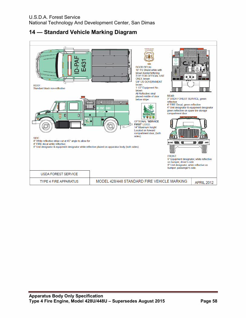
U.S.D.A. Forest Service National Technology And Development Center, San Dimas
Apparatus Body Only Specification Type 4 Fire Engine, Model 428U/448U – Supersedes August 2015 Page 58
14 — Standard Vehicle Marking Diagram