Embed Size (px)
Citation preview

1
Type 2001 Series GRANGER™ Elliptically Polarized Broadband Antennas
Broadband 2-30 MHz Frequency Range
Up to 25 kW Average, 50 kW Peak Power Rating
Horizontal-Elliptical Polarization to Reduce Fading
Full Efficiency – No Resistive Loading
Omindirectional
2.0:1 Maximum VSWR
Short-to-Medium-Range Communications
On-Site Selection of Polarization Sense
General Description The Type 2001 Series antenna was developed to fill the need for a more efficient broadband antenna, capable of providing radiation characteristics essential for reliable short-to medium-range communications. Vertically polarized antennas cannot always provide reliable short-range coverage because of limitations in the radiation pattern or excessive attenuation of the ground wave. Existing horizontally polarized antennas are limited in the capacity to provide reliable medium-range communications because of lack of control of radiation patterns over adequate frequency ranges. With the elliptically polarized Type 2001 antennas, communication performance beyond that achieved
with either vertically or horizontally polarized antennas is possible. Features Improved Reliability. The use of elliptical polarization has proven to be effective in avoiding deep fading because of polarization nulls caused by ionospheric rotation of the electric field. In 1966, an antenna was introduced, based on the log spiral principle, which provides horizontal elliptical polarization. Previous studies and subsequent real-time use have demonstrated that this type of polarization significantly reduces the effects of polarization null fading. Short-range circuits are particularly subject to this kind of fading, which

2
Type Frequency Range, MHz Power Rating, kW Polarization Input Impedance, ohms
Omnidirectional broadband 2.0, 2.85 or 4-30 Up to 25 average, 50 peak Elliptical-either sense depending upon connection of radiators to feedline at time of installation. 50, coaxial
VSWR Gain, dBi Azimuth Plane Radiation Pattern Efficiency Wind Survival Rating, mph (km/h) Without Ice With 0.5 in (12mm) Radial Ice
2.0:1 maximum 5 minimum; 7 maximum Omnidirectional Greater than 95% 140 (225) 90 (145)
The sense of polarization (clockwise or counterclockwise) is uniquely determined by the location of the antenna in the Northern or Southern Hemisphere. These exacting requirements make on-site selection of the sense of the elliptical polarization mandatory. The 2001 antenna has been designed to accommodate onsite selection of the polarization sense by station personnel, with ordinary tools. This feature provides significant savings in logistics costs. Omnidirectional. The omnidirectional azimuth plane pattern provides optimum coverage for communications centers, airports and ground-air and shore stations for shore-ship communications. Accessories The following accessories are available for ease of installation and maintenance: tower lighting kit, erection kit, paint kit, tool kit, lighting rod kit, anti-climbing kit, and spares kit.
reduces circuit reliability. The 2001 Series antenna has both this very effective elliptical polarization and, in addition, is highly efficient (no lossy terminators) at all frequencies in the 20-30 MHz range. All circuits are subject to some degree of take-off angle change, and it is imperative to have a radiation pattern free of nulls. Nulls are present at very high take-off angles with a vertical antenna such as a whip or conical monopole. Tuned dipoles, mounted a constant height above the ground, have frequency variable nulls at medium angles which inhibit circuit performance at medium ranges. The 2001 Series antenna maintains a continuity of elevation plane pattern at all frequencies and gives reliable continuous coverage over variable circuit distances. On-Site Selection of Polarization. The property of the ionosphere which causes fading also makes the use of an elliptically polarized signal desireable.
Characteristics

3
Typical Elevation Plane Patterns
Typical Azimuth Plane Patterns
Bulletin 1422B 05/08 Data subject to change without notice. 4 ASC Signal Corporation • 606 Beech Street West • Whitby, Ontario, Canada • L1N 5S2 • t. +1 (905) 668 3348 • f. +1 (905) 668 8590 • www.ascsignal.com
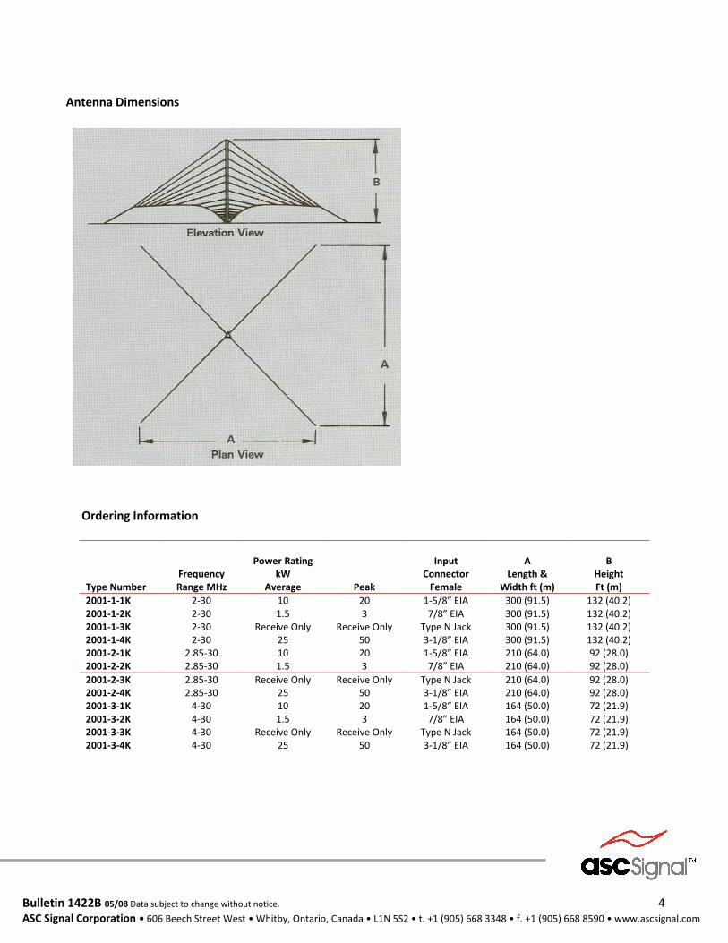
Type Number
Frequency Range MHz
Power Rating
kW Average
Peak
Input
Connector Female
A
Length & Width ft (m)
B
Height Ft (m)
2001-1-1K 2001-1-2K 2001-1-3K 2001-1-4K 2001-2-1K 2001-2-2K
2-30 2-30 2-30 2-30
2.85-30 2.85-30
10 1.5
Receive Only 25 10 1.5
20 3
Receive Only 50 20 3
1-5/8” EIA 7/8” EIA
Type N Jack 3-1/8” EIA 1-5/8” EIA 7/8” EIA
300 (91.5) 300 (91.5) 300 (91.5) 300 (91.5) 210 (64.0) 210 (64.0)
132 (40.2) 132 (40.2) 132 (40.2) 132 (40.2) 92 (28.0) 92 (28.0)
2001-2-3K 2001-2-4K 2001-3-1K 2001-3-2K 2001-3-3K 2001-3-4K
2.85-30 2.85-30
4-30 4-30 4-30 4-30
Receive Only 25 10 1.5
Receive Only 25
Receive Only 50 20 3
Receive Only 50
Type N Jack 3-1/8” EIA 1-5/8” EIA 7/8” EIA
Type N Jack 3-1/8” EIA
210 (64.0) 210 (64.0) 164 (50.0) 164 (50.0) 164 (50.0) 164 (50.0)
92 (28.0) 92 (28.0) 72 (21.9) 72 (21.9) 72 (21.9) 72 (21.9)
Antenna Dimensions
Ordering Information


![Parametric Study of Ultra-Wideband Dual Elliptically Tapered ...The dual elliptically tapered antipodal slot antenna (DE-TASA) [ 11, 12] is a modified version of the antipodal Vivaldi](https://img.pdfslide.us/doc/110x75/60c1f920f08e4e2a4478d5eb/parametric-study-of-ultra-wideband-dual-elliptically-tapered-the-dual-elliptically.jpg)